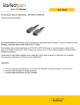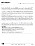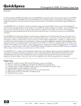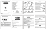
1
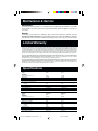
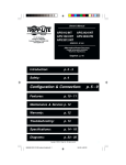
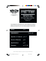
Owner's Manual
PV 500FC
PV 1000FC
1111 W. 35th Street
Chicago, IL 60609 USA
Customer Support: (773) 869-1234
www.tripplite.com
PV 2000FC
PV 2400FC
PowerVerter Plus®
120V, 60 Hz Output
DC-to-AC Power Inverters
• Voltage- and Frequency-Controlled
• High Peak Power, High Efficiency
Español: p. 9
Your PowerVerter Plus converts DC power from connected batteries into AC power for
connected equipment. It can provide up to twice its continuous output rating for short periods,
enabling it to run electrical devices such as motors that have a high power demand at startup.
Read this manual carefully to learn how to connect, operate and maintain your PowerVerter Plus.
Safety:
p. 2
Installation:
p. 3 - 5
Operation & Features: p. 6 - 7
Service & Warranty:
p. 8
Specifications:
p. 8
Diagrams:
p. 17 - 20
Copyright © 2000 Tripp Lite. All rights reserved. PowerVerter® is a registered trademark of Tripp Lite.
1
200002001 CURRENT PV 500-2400FC.p65
1
4/12/00, 1:44 PM
Safety
This manual contains important instructions and warnings that should be followed during the
installation, operation and storage of all Tripp Lite PowerVerter Systems.
PowerVerter Location Warnings
• Install your PowerVerter indoors, away from excess moisture or heat, dust or direct
sunlight.
• Do not attempt to mount your PowerVerter on a vertical surface.
• Leave adequate space around all sides of the PowerVerter for proper ventilation. The
more power connected equipment draws, the more heat will be generated by the
PowerVerter.
• Do not install the PowerVerter near magnetic data storage media, as this may result in
data corruption.
Battery Connection Warnings
• Your PowerVerter will not operate until batteries are connected.
• Multiple battery systems must be made up of batteries of the same voltage, age, amp
hour capacity and type.
• Keep battery location well ventilated. Explosive hydrogen gas can accumulate near
batteries if they are not kept well ventilated.
• Sparks may result during final battery connection. Always observe proper polarity as
batteries are connected.
• Tighten your battery terminals to create an efficient battery connection and prevent
excessive heating.
• Do not allow objects to contact the two DC input terminals. Do not short or bridge these
terminals together. Serious injury to property or person could result.
Equipment Connection Warnings
• Do not use Tripp Lite PowerVerter Systems in life support applications where a
malfunction or failure of a Tripp Lite PowerVerter System could cause failure or
significantly alter the performance of a life support device.
• Do not connect a surge suppressor, line conditioner or UPS to the output of the
PowerVerter.
Operation Warnings
• Your PowerVerter does not require routine maintenance. Do not open your PowerVerter
for any reason. There are no user-serviceable parts inside.
• Potentially lethal voltages exist within this unit as long as the batteries are connected.
During any service work, the batteries should therefore be disconnected.
• Do not connect or disconnect batteries while the PowerVerter is operating. Dangerous
arcing may result.
2
200002001 CURRENT PV 500-2400FC.p65
2
4/12/00, 1:44 PM
Installation Overview
1) Mount PowerVerter (Mounting, p. 3)
2) Select Battery(ies) (Battery Selection, p. 4)
3) Connect Battery(ies) (Battery Connection, p. 5)
4) Connect Equipment (Outlets, p. 6)
5) Turn PowerVerter On (Power Switches, p. 6)
Mounting (Optional*)
*Recommended for all Vehicular and Marine Applications
Due to their size and weight, the PowerVerter Plus systems in this manual should be mounted directly
to a rigid horizontal surface, mounting plate or bracket before battery connection. User must supply
all fasteners and brackets. Turn your PowerVerter and connected equipment OFF before mounting.
Mounting for the PV 500FC or PV 1000FC (See Diagram 1, p. 17)
• Install four 5mm (#8) fasteners (A) into a rigid horizontal surface using the measurements
in the diagram. Leave the heads of the fasteners raised slightly above the surface in order
to engage the keyhole slots molded into the bottom of the PowerVerter's feet.
• Place keyhole slots in the PowerVerter's four feet over the four fasteners and slide the
PowerVerter forward or backward to secure it. Install an "L"-shaped brackets (B) as shown
to permanently hold the PowerVerter in position.
Mounting for the PV 2000FC or 2400FC (See Diagram 2, p. 17)
• Install two 8 mm (1/4 in.) fasteners (A) into a rigid horizontal surface using the measurements
in the diagram. (Leave the heads of fasteners raised slightly above the horizontal surface
in order to engage the slots in the PowerVerter's two front feet.)
• Slide PowerVerter forward to fully engage the fasteners in the PowerVerter's front feet. Install
two 8 mm (1/4 in.) fasteners (B) into the horizontal surface, through the slots in the PowerVerter's two rear feet. Tighten the screws to permanently hold your PowerVerter in position.
Splash Guard (PV 500FC and PV 1000FC Models Only)
(Optional; Recommended for all Marine Applications)
When adding a splash guard to a PowerVerter for use in a damp environment, spacers must be
used to maintain a proper ventilation for the inverter. User must supply splash guard, screws and
spacers. Turn your PowerVerter and connected equipment OFF before mounting.
Adding a Splash Guard for the PV 500FC or PV 1000FC (See Diagram 3, p. 17)
• Thread four 4mm (#8) sheet metal screws (A) through four holes in a rigid horizontal splash
guard (B) measuring 175 mm x 225 mm, through four 25mm long hollow spacers (C) and
into the four blind holes in the top panel of your PowerVerter.
3
200002001 CURRENT PV 500-2400FC.p65
3
4/12/00, 1:44 PM
Battery Selection
Selecting Battery Type
Select a battery or system of batteries that will provide your PowerVerter with proper DC voltage
and an adequate amp hour capacity. Select ‘Deep-Cycle’ batteries to enjoy optimum performance
from your PowerVerter. Batteries of either Wet-Cell (vented) or Gel-Cell/Absorbed Glass Mat (sealed)
construction are ideal. 6 Volt “golf-cart,” Marine Deep-Cycle or 8D Deep-Cycle batteries are also
acceptable.
Selecting Battery Amp-Hour Capacity
If you plan to connect your batteries to a vehicle's alternator or another charging
current, Step 1:
Add the Wattage Ratings of your connected equipment to determine the Total Wattage Required.*
Step 2:
Divide the Total Wattage Required (from Step 1) by the PowerVerter's DC input voltage (either 12V
or 24V; see specifications) to determine the DC Amperes Required.
Step 3:
Multiply the DC Amperes Required (from Step 2) by the number of hours you will want to run your
equipment from battery power to determine a Battery Amp-Hours Required Rough Estimate.
Step 4:
Compensate for inefficiency by multipling your Battery Amp-Hour Required Rough Estimate (from
Step 3) by 1.2 to determine how many amp-hours of battery power (from one or several batteries)
you should connect to your PowerVerter. Note that the Amp-Hour ratings of batteries are usually
given for a 20 hour discharge rate. Actual Amp-Hour capacities are less when batteries are
discharged at faster rates: batteries discharged in 55 minutes provide only about 50% of their listed
Amp-Hour ratings, while batteries discharged in 9 minutes provide as little as 30% of their Amp-Hour
ratings.
Example: A park ranger wants to be able to power emergency lights off of 12V batteries for up to an hour after an AC power
outage. She divides the total wattage of her equipment (150 watts) by her PowerVerter's DC input voltage (12V) and
multiplies by 1 hour to get a Battery Amp-Hours Required Rough Estimate of 12.5. She multiplies this by 1.2 (for inefficiency)
then divides by 50% (since a battery that discharges in an hour only provides about 50% of its stated amp-hour capacity)
and determines that her 12V batteries' amp-hour capacities must add up to at least 30.
* The wattage rating is usually stated in a device's manual or on its nameplate. If your equipment is rated in amps rather
than watts, you can approximate its watt rating by multiplying its ampere rating by its input voltage (120).
4
200002001 CURRENT PV 500-2400FC.p65
4
4/12/00, 1:44 PM
Battery Connection
PowerVerter Plus inverters are often connected to vehicle batteries that are recharged by the
vehicle's alternator. The following directions describe several possible vehicular connections.
PowerVerter Plus inverters are also suitable for use with battery banks that are recharged by
gas generators; utility power; wind, water or solar generators and other AC sources. The
following directions can be adapted for the connection of a PowerVerter to such a battery bank,
replacing the alternator in the connection diagrams with the variant charging system. The user
must determine the proper connection method for the variant charging system. Never operate
a PowerVerter directly from an alternator or other charger—always connect both to an
intermediate battery system.
1. Connect your PowerVerter's positive DC Terminal directly
to a fuse.
Tripp Lite strongly recommends that you install a recognized UL component fuse block and
fuse within 18 inches of the battery. The fuse's rating must equal or exceed the Minimum DC
Fuse Rating listed in your PowerVerter model's specifications on page 8.
2. Choose a battery configuration appropriate to your batteries
and PowerVerter model.
• Single Battery Vehicular Connection: Refer to Diagram 4, page 18 to connect a PV 2000FC
or 2400FC, or refer to Diagram 7 on page 19 to connect a PV 500FC or 1000FC. Use this basic
connection if you plan to use your PowerVerter to power small loads for brief periods of time
from a single vehicle battery. When using a single battery, its voltage must be equal to the
voltage of your PowerVerter's Inverter Nominal Input Voltage (see specs.)
• Series Battery Vehicular Connection: Refer to Diagram 5, page 18 to connect a PV 2000FC
or 2400FC, or refer to Diagram 8 on page 19 to connect a PV 500FC or 1000FC. Use this
advanced connection if you plan to use your PowerVerter to power small loads for brief periods
of time using several low-voltage batteries. When using multiple batteries in series, all batteries
must be equal in age, voltage and amp hour capacity, and the sum of their voltages must be
equal to the voltage of your PowerVerter's Inverter Nominal Input Voltage (see specs.)
• Parallel Battery Vehicular Connection: Refer to Diagram 6, page 18 to connect a PV 2000FC
or 2400FC, or refer to Diagram 9 on page 19 to connect a PV 500FC or 1000FC. Use this
advanced connection to if you plan to use your PowerVerter to power large loads for long
periods of time using a battery bank. This connection uses a battery isolator to provide power
from a parallel battery bank without draining the vehicle's battery. When using multiple batteries
in parallel, each battery's voltage must be equal to the voltage of your PowerVerter's Inverter
Nominal Input Voltage (see specs.)
3. Use SHORT, HEAVY GAUGE battery cabling.
Use #4 cabling with the PV 500FC and PV 1000FC; use #2/0 cabling with the PV 2000FC and
PV 2400FC. Make the battery connection cable lengths as short as possible, and in no case
longer than 10 feet. Shorter and heavier gauge cabling limits DC voltage drop and allows
maximum transfer of current.* You must tighten your battery terminals to approximately 4
Newton-meters of torque to create an efficient battery connection and prevent excessive
heating; insufficiently tightening the terminals could void your PowerVerter's warranty.
*PowerVerter Plus models are capable of delivering a much higher wattage output for brief periods of time. Wiring
should be configured to handle this brief high-current draw. Though your PowerVerter is a high-efficiency
converter of electricity, its rated output capacity is limited by the length and gauge of the wires running from the
battery to the PowerVerter.
5
200002001 CURRENT PV 500-2400FC.p65
5
4/12/00, 1:44 PM
Operation & Features
(See Diagram 10, p. 20 to locate the following switches, indicator lights and other features.)
Outlets
1. AC Receptacles (All models)
These output receptacles provide AC power to connected equipment. The PV 500FC and the PV
1000FC feature NEMA 5-15 receptacles, while the PV 2000FC and 2400FC feature NEMA 5-20
receptacles. Plug your equipment into these outlets as if they were utility (wall) AC outlets. Note:
the total power demand of all equipment connected to your PowerVerter's output receptacles must
not exceed your PowerVerter's power ratings (see Specifications, p. 8 for your model's Continuous
and Surge Power Ratings). Also note that these outlets provide no connection to ground.
Power Switches
2. OFF—ON Switch (PV 500FC and PV 1000FC)
• Move this switch to the ON position to have your PowerVerter provide connected
equipment with AC power by converting DC power from an attached battery.
• Move this switch to the ON position to control the PowerVerter at a distance with a usersupplied on/off switch.
• Leave this switch in the OFF position when not using connected equipment to prevent battery
drain.
3. REMOTE—OFF—ON Switch (PV 2000FC and PV 2400FC)
• Set this 3-position switch to REMOTE to control your PowerVerter at a distance with a Tripp Lite
PV/APS Remote (sold seperately).
• Move this switch to the ON position to have your PowerVerter provide connected equipment with
AC power by converting DC power from an attached battery.
• Leave this switch in the OFF position when not using connected equipment to prevent battery
drain.
Indicator Lights
4. LOAD LOW/MED/HIGH LEDs (All models)
These three lights show the approximate power demand on your PowerVerter Plus.
LEDs Illuminated
Green
Green & yellow
Yellow
Red
All three lights off
Flashing red, twice/second
Flashing red, 4 times/second
Approximate Load
0% - 50%
51% - 75%
76% - 100%
100% - 125%
Inverter off
Overload
Overload (Inverter shutdown)
6
200002001 CURRENT PV 500-2400FC.p65
6
4/12/00, 1:44 PM
5. BATTERY HIGH/MED/LOW (All models)
These three lights will turn ON in several sequences to show the approximate charge level and
voltage of your connected battery bank and alert you to several fault conditions:
LEDs Illuminated
Green
Green & yellow
Yellow
Yellow & red
Red
Flashing red, twice/second
Flashing red, 4 times/second
Capacity
Full
80% - Full
60% - 80%
40% - 60%
20% - 40%
0% - 20%
0% (Inverter shutdown)
Other Features
6. DC Input Terminals (All models)
The terminals' lug screws or wing nuts secure the wires leading from your external battery or battery
system. Your battery or battery system must provide your PowerVerter with proper DC voltage and
your equipment with an adequate amp hour capacity. See Battery Selection section, pg. 4 for more
information.
7. Resettable Circuit Breaker (All models)
The circuit breaker protects your PowerVerter against damage due to output overload. If the breaker
trips, remove some of the load on the PowerVerter to prevent overload, then wait 1 minute to allow
components to cool before resetting the circuit breaker.
8. Remote On/Off Switch Connector (PV 500FC and PV 1000FC)
This jack can be used to connect a user-supplied corded on/off switch for remote control.
9. APS/PV Remote Connector (PV 2000FC and PV 2400FC)
This RJ11 jack can be used to connect an optional Tripp Lite APS/PV Remote (sold seperately) to
monitor and control the operation of the PowerVerter at a distance. See the instructions packed with
the APS/PV Remote for installation, operation and maintenance.
7
200002001 CURRENT PV 500-2400FC.p65
7
4/12/00, 1:44 PM
Maintenance & Service
Maintenance
Your PowerVerter model requires no maintenance but should be kept dry at all times. Periodically
check all cable connections both at the unit and at the battery. Clean and tighten connections as
necessary.
Service
If returning your PowerVerter to Tripp Lite, please pack the PowerVerter carefully, using the
ORIGINAL PACKING MATERIAL that came with the unit. Enclose a letter describing the symptoms
of the problem. If the PowerVerter is within the warranty period, enclose a copy of your sales receipt.
Limited Warranty
Tripp Lite warrants its products to be free from defects in materials and workmanship for a period of one year (domestic) or 120 days (export)
from the date of initial purchase. Tripp Lite’s obligation under this warranty is limited to repairing or replacing (at its sole option) any such
defective products. To obtain service under this warranty you must obtain a Returned Material Authorization (RMA) number from Tripp Lite
or an authorized Tripp Lite service center. Products must be returned to Tripp Lite or an authorized Tripp Lite service center with transportation
charges prepaid and must be accompanied by a brief description of the problem encountered and proof of date and place of purchase. This
warranty does not apply to equipment which has been damaged by accident, negligence or misapplication or has been altered or modified in
any way. This warranty applies only to the original purchaser who must have properly registered the product within 10 days of purchase.
EXCEPT AS PROVIDED HEREIN, TRIPP LITE MAKES NO WARRANTIES, EXPRESS OR IMPLIED, INCLUDING WARRANTIES OF
MERCHANTABILITY AND FITNESS FOR A PARTICULAR PURPOSE. Some states do not permit limitation or exclusion of implied
warranties; therefore, the aforesaid limitation(s) or exclusion(s) may not apply to the purchaser.
EXCEPT AS PROVIDED ABOVE, IN NO EVENT WILL TRIPP LITE BE LIABLE FOR DIRECT, INDIRECT, SPECIAL, INCIDENTAL OR
CONSEQUENTIAL DAMAGES ARISING OUT OF THE USE OF THIS PRODUCT, EVEN IF ADVISED OF THE POSSIBILITY OF SUCH
DAMAGE. Specifically, Tripp Lite is not liable for any costs, such as lost profits or revenue, loss of equipment, loss of use of equipment, loss
of software, loss of data, costs of substitutes, claims by third parties, or otherwise.
Specifications
MODEL:
Weight:
INVERTER
Continuous power (@ 20° C):
Surge power:
Efficiency (Full Load):
Minimum DC Fuse Rating:
DC Input Current @ Nominal V DC
Full Load
No Load
Nominal DC Input:
DC Input Voltage Range:
Nominal Output Volts:
Nominal Output Frequency:
MODEL:
Weight:
INVERTER
Continuous power (@ 20° C):
Surge power :
Efficiency (Full Load):
Minimum DC Fuse Rating:
DC Input Current @ Nominal V DC
Full Load
No Load
Nominal DC Input:
DC Input Voltage Range:
Nominal Output Volts:
Nominal Output Frequency:
PV 500FC
15 lbs.
PV 1000FC
20 lbs.
500 W
1000 W
90%
100 A
1000 W
2000 W
90%
200 A
50 A
2.2 A
12 VDC
10-15 VDC
120 VAC ±5%
60 Hz ±.3%
100 A
2.2 A
12 VDC
10-15 VDC
120 VAC ±5%
60 Hz ±.3%
PV 2000FC
37lbs.
PV 2400FC
40 lbs.
2000 W
4000 W
90%
400 A
2400 W
4800 W
90%
250 A
200 A
2.2 A
12 VDC
10-15 VDC
120 VAC ±5%
60 Hz ±.3%
120 A
2.2 A
24 VDC
20-30 VDC
120 VAC ±5%
60 Hz ±.3%
8
200002001 CURRENT PV 500-2400FC.p65
8
4/12/00, 1:44 PM
Diagrams/Diagramas Esquemáticos
2
1
3
17
200002001 CURRENT PV 500-2400FC.p65
17
4/12/00, 1:44 PM
4
4.1
X Volts
4.4
4.3
4.2
PV
Single Battery Vehicular Connection.
PV 2000FC or PV 2400FC. See Pg.5.
4.1 is the alternator
4.2 is the vehicle battery ground
4.3 is the vehicle battery
4.4 is the fuse
Conexión de Una Batería en Vehículos.
PV 2000FC o PV 2400FC. Vea página 13.
4.1 representa el alternador
4.2 representa la conexión a tierra de la batería del vehículo
4.3 representa la batería del vehículo
4.4 representa el fusible
X = Your APS's Inverter's Nominal Input Voltage.
(See specifications)
X = El Voltaje Nominal de Entrada del Inversor del APS.
(Vea las especificaciones).
5
5.1
5.3
5.3
X/2 Volts
X/2 Volts
5.4
5.2
PV
Conexión en Serie de Baterías en Vehículos.
PV2000FC o PV 2400FC. Vea página 13.
5.1 representa el alternador
5.2 representa la conexión a tierra de la batería del vehículo
5.3 representa la batería del vehículo
5.4 representa el fusible
Series Battery Vehicular Connection.
PV 2000FC or PV 2400FC. See Pg.5.
5.1 is the alternator
5.2 is the vehicle battery ground
5.3 is the vehicle battery
5.4 is the fuse
X = Your PV's Nominal Input Voltage.
(See specifications)
X = El Voltaje Nominal de Entrada del Inversor del PV.
(Vea las especificaciones).
6
6.4
6.3
6.1
X Volts
6.2
6.5
6.5
6.5
6.3
PV
X Volts
X Volts
X Volts
6.6
Parallel Battery Vehicular Connection.
PV 2000FC or PV 2400FC. See Pg.5.
6.1 is the alternator
6.2 is a battery isolator
6.3 is the vehicle battery ground
6.4 is the vehicle battery
6.5 are auxiliary vehicle batteries
6.6 is the fuse
Conexión Paralela de Baterías en Vehículos.
PV 2000FC o PV 2400FC. Vea página 13.
6.1 representa el alternador
6.2 representa el aislador de la batería
6.3 representa la conexión a tierra de la batería
6.4 representa la baterÍa del vehiculo
6.5 representa la batería auxiliar del vehículo
6.6 representa el fusible
X = Your PV's Nominal Input Voltage.
(See specifications)
X = El Voltaje Nominal de Entrada del PV.
(Vea las especificaciones).
18
200002001 CURRENT PV 500-2400FC.p65
18
4/12/00, 1:44 PM
7.1
7.4
7
7.3
X Volts
Single Battery Vehicular Connection.
PV 500FC or PV 1000FC. See Pg.5.
7.1 is the alternator
7.2 is the vehicle battery ground
7.3 is the vehicle battery
7.4 is the fuse
PV
Conexión de Una Batería en Vehículos.
PV 500FC o PV 1000FC. Vea página 13.
7.1 representa el alternador
7.2 representa la conexión a tierra de la batería del vehículo
7.3 representa la batería del vehículo
7.4 representa el fusible
7.2
X = El Voltaje Nominal de Entrada del PV.
(Vea las especificaciones).
X = Your PV's Nominal Input Voltage.
(See specifications)
8.1
8
8.4
X/2 Volts
X/2 Volts
8.3
8.3
PV
8.2
Series Battery Vehicular Connection.
PV 500FC or PV 1000FC. See Pg.5.
8.1 is the alternator
8.2 is the vehicle battery ground
8.3 is the vehicle battery
8.4 is the fuse
Conexión en Serie de Baterías en Vehículos.
PV 500FC o PV 1000FC. Vea página 13.
8.1 representa el alternador
8.2 representa la conexión a tierra de la batería del vehículo
8.3 representa la batería del vehículo
8.4 representa el fusible
X = Your PV's Nominal Input Voltage.
(See specifications)
X = El Voltaje Nominal de Entrada del PV.
(Vea las especificaciones).
9
X Volts
9.5
9.3
9.1
X Volts
X Volts
9.5
9.5
9.6
PV
9.2
9.4
X Volts
9.3
Parallel Battery Vehicular Connection.
PV 500FC or PV 1000FC. See Pg.5.
9.1 is the alternator
9.2 is a battery isolator
9.3 is the vehicle battery ground
9.4 is the vehicle battery
9.5 are auxiliary vehicle batteries
9.6 is the fuse
Conexión Paralela de Baterías en Vehículos.
PV 500FC o PV 1000FC. Vea página 13.
9.1 representa el alternador
9.2 representa el aislador de la batería
9.3 representa la conexión a tierra de la batería
9.4 representa la baterÍa del vehiculo
9.5 representa la batería auxiliar del vehículo
9.6 representa el fusible
X = Your PV's Nominal Input Voltage.
(See specifications)
X = El Voltaje Nominal de Entrada del PV.
(Vea las especificaciones).
19
200002001 CURRENT PV 500-2400FC.p65
19
4/12/00, 1:46 PM
8
5
2
4
10
1
A. PV 500FC
PV 1000FC
7
6
B. PV 2000FC
PV 2400FC
5
9
120
4
3
60
7
1
6
1. AC Receptacles (All Models)
2. Off–On Switch (PV 500FC and PV 1000FC)
3. Remote–Off–On Switch (PV 2000FC and PV 2400FC)
4. Load Low/Med/High LEDs (All Models)
5. Battery High/Med/Low LEDs (All Models)
6. DC Input Terminals (All Models)
7. Resettable Circuit Breaker (All Models)
8. Remote On/Off Connector (PV 500FC and PV 1000FC)
9. APS/PV Remote Connector (PV 2000FC and PV 2400FC)
1. Receptáculos de CA
(Solamente en los modelos con cable de CA)
2. Interruptor de Encendido/Apagado (PV 500FC y
PV 1000FC)
3. Interruptor de Remoto/Encendido/Apagado
(PV 2000FC y PV 2400FC)
4. Luces Indicadoras de Carga Baja/Media/Alta
(Todos los modelos)
5. Carga de Baterías Alta/Media/Baja
(Todos los modelos)
6. Terminales de Entrada de CD (Todos los modelos)
7. Interruptor de Circuito con Restablecimiento
(Todos los modelos)
8. Conector para el Módulo de Control Remoto
(PV 500FC y PV 1000FC)
9. Conector para el Módulo de Control Remoto
(PV 2000FC y PV 2400FC)
93-1551 (200002001) 0400
20
200002001 CURRENT PV 500-2400FC.p65
20
4/12/00, 1:46 PM
1111 W. 35th Street, Chicago, IL 60609 USA
773.869.1234 (USA) • 773.869.1212 (International)
www.tripplite.com
200002001 93-1551_EN