1
5.5 HP 2 Stage
Snow Thrower
SKU #270-3250
Owner's
Manual
DO NOT
RETURN
Questions?
Please
call our
PLEASE
THROWER.
READ
THIS ENTIRE
MANUAL
BEFORE
customer
USING
Please keep this manual available to all users during the entire life of the snow thrower.
2005 Yardworks(R).
Do not reprint
without
written
help
line:
M-F 84 CT
Thank you for purchasing a Yardworks ®snow thrower. This manual provides information
regarding the setup, operation, and maintenance of this product. We have made every effort to
ensure the accuracy of the information in this manual. The manufacturer reserves the right to
change this product at any time without prior notice.
Copyright
STORE
Problems?
(888) 315-3080
IMPORTANT:
THIS SNOW
TO
authorization.
TABLE
OF CONTENTS
GENERAL SAFETY PROCEDURES ........................................................................
PACKAGE CONTENTS .......................................................................................
SNOW THROWER COMPONENTS .........................................................................
ENGINE COMPONENTS ......................................................................................
ASSEMBLY .....................................................................................................
Chute Assembly ........................................................................................
Handle Assembly .......................................................................................
Attaching Drive Speed Control Lever ...............................................................
Chute Rotation Handle .................................................................................
Drive Control and Auger Control Cable Assembly ................................................
PREPARING THE SNOW THROWER FOR USE ........................................................
Visually Inspect the Snow Thrower ...................................................................
Check Tire Inflation ....................................................................................
Add/Check Oil ..........................................................................................
Add/Check Gasoline ...................................................................................
Adjust Skid Shoes ......................................................................................
OPERATION .....................................................................................................
Starting the Snow Thrower ............................................................................
Using the Snow Thrower ..............................................................................
STOPPING THE SNOW THROWER .......................................................................
STORAGE/TRANSPORT PROCEDURES ................................................................
MAINTENANCE / CARE .....................................................................................
Cleaning the Snow Thrower ...........................................................................
Clearing Auger or hnpeller Jams ....................................................................
Checking Tire Pressure ................................................................................
Checking/Adding Oil ..................................................................................
Replacing The Oil .......................................................................................
Air Filter Maintenance .................................................................................
Spark Plug Maintenance ...............................................................................
Emptying the Gas Tank ................................................................................
Adjusting Drive and Auger Cables ...................................................................
Replacing Shear Pins ...................................................................................
SPECIFICATIONS ..............................................................................................
TROUBLESHOOTING .........................................................................................
SNOW THROWER EXPLODED VIEW ....................................................................
SNOW THROWER PARTS LIST .............................................................................
ENGINE EXPLODED VIEW .................................................................................
ENGINE PARTS LIST ..........................................................................................
WARRANTY .....................................................................................................
3
6
7
8
9
9
9
10
11
11
13
13
13
13
14
15
16
16
17
19
19
20
20
21
21
21
22
23
24
24
25
26
27
27
29
30
31
32
33
GENERAL
SAFETY
PROCEDURES
Pleasefamiliarizeyourselfwith the following safetysymbolsandwords:
The safety alert symbol A is used with one of the safety words (DANGER, CAUTION,
or WARNING)
to alert you to hazards. Please pay attention to these hazard notices both
in this manual and on the snow thrower.
DANGER: Indicates
not followed.
a hazard that will result in serious injury or death if instructions
are
WARNING: Indicates a strong possibility of causing serious injury or death if
instructions are not followed.
CAUTION: Indicates a possibility of personal injury or equipment damage if
instructions are not followed.
O
If you have any questions
manual or on the product,
snow thrower.
regarding
the hazard
please call (888)
and safety notices listed in this
315-3080
M-F 8-5CT before using the
A DANGER: This snow thrower produces poisonous carbon monoxide gas when
running.
This gas is both odorless and colorless. Even if you do not see or smell
gas, carbon monoxide may still be present. Breathing this poison can lead to
headaches,
dizziness, drowsiness, and eventually death.
• Use outdoors ONLY in non-confined areas.
A WARNING:
The exhaust from this product contains
cancer, birth defects, or other reproductive
harm.
chemicals
known to cause
WARNING: This snow thrower may emit highly flammable and explosive
gasoline vapors, which can cause severe burns or even death. A nearby open flame
can lead to explosion even if not directly in contact with gas.
• Do not operate near open flame.
• Do not smoke near snow thrower.
•
•
•
•
•
Always turn snow thrower off before refueling. Allow snow thrower to cool for
at least 2 minutes before removing fuel cap. Loosen cap slowly to relieve
pressure in tank.
Do not overfill gas tank. Gas may expand during operation. Do not fill to the top
of the tank.
Always check for spilled gas before operating.
Empty gasoline tank before storing or transporting the snow thrower.
Before transporting, turn fuel valve to off and disconnect spark plug.
A WARNING:
Foreign objects entering the auger or impeller can create clogs,
jams, projectiles,
and other dangerous conditions.
• Do not use in the path of wires, doormats, snow toys, or other foreign objects.
• If the snow thrower intakes a foreign object, stop the engine, wait for the auger
and impeller to stop rotating, and inspect the snow thrower for damage.
• Turn off the engine and make sure that all moving parts have stopped before
clearing any clogs or jams.
• If the snow thrower makes any abnormal sounds or vibrations, stop the engine
and inspect the snow thrower.
• Use extreme caution when operating on or near dirt or gravel roads.
A WARNING: The auger and impeller rotate at fast speeds that can cause
damage or even amputation
of body parts. Even if you do not see the auger or
impeller rotating, they may start at any time if the engine is running.
• Always turn off the engine before attempting to clear any clogs or jams.
• Keep hands and feet away from rotating parts while the engine is running.
• Do not wear loose fitting clothing that can become entangled in rotating parts.
A WARNING:
This snow thrower is intended for use in conditions that are cold,
slippery, and otherwise naturally hazardous.
Take precautions
when operating
machinery
in these conditions.
• Always wear warm clothing and shoes intended for slippery surfaces.
• Always operate in daylight with good visibility.
• Never run with snow thrower and be alert to all surrounding people and traffic.
• Do not operate the snow thrower on steep inclines.
• Disengage the drive mechanism to neutral before starting the engine.
• Always hold on to the handles while operating. Never leave the snow thrower
while the engine is running.
A WARNING:
This snow thrower produces
near exhaust can exceed 150°F (65 ° C).
• Do not touch hot surfaces. Pay attention
denoting hot parts of the machine.
• Even in cold conditions, allow the snow
before touching engine or areas that heat
heat when running.
to warning
Temperatures
labels on the snow thrower
thrower to cool several minutes after use
during use.
CAUTION:
Misuse of this snow thrower can damage it or shorten its life.
• Use the snow thrower only for its intended purposes.
• After starting the engine, allow it to adjust to outdoor temperatures before
clearing snow.
• Do not attempt to clear snow at too fast a rate, as this may overload the snow
thrower.
• Use only Yardworks :_:approved attachments or replacement parts with this snow
thrower.
•
Never make adjustments
to the snow thrower while the engine is running.
A WARNING: In addition
to the above warnings please note the following
precautions that should be followed when operating this or ANY machine.
• Read all manuals and warning labels before using a machine.
• Never operate a machine with any guard or cover removed.
• Remove all adjusting keys and wrenches before use.
• Do not allow children or uninstructed persons to operate.
• Use the right tool. Do not force the tool or attachment to do a job for which it was
not designed.
• Do not wear loose clothing, neckties, or jewelry that can get caught in moving
parts. Wear a protective hair covering to contain long hair. Do not wear opentoed shoes.
•
•
•
•
Do not overreach. Keep proper footing and balance at all times.
Always wear safety glasses when operating.
Always store machines in a clean dry area free from grease and oil. Never use
petroleum based products or any solvents to clean a tool.
Allow motor to come up to full speed before operating.
In addition to the above safety notices, please familiarize
hazard markings on the snow thrower.
yourself
with the safety and
PACKAGE
CONTENTS
Your snow thrower comes with the items listed below.
following items are included with your snow thrower.
O
(888)
ITEM
If you are
315-3080
missing
M-F
components
DO NOT
8-5 CT for customer
Please check to see that all of the
RETURN
TO
STORE,
please
call
service.
LIST
Handle
assembly
Snow thrower
&
Chute assembly
Chute rotation
handle
Drive speed
control handle
Replacement
shear bolts
(2 pcs)
Assembly
hardware
Instruction
manual and
registration card
Spark plug
wrench
Set of three
wrenches for
assembly
SNOW
THROWER
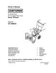
COMPONENTS
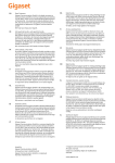
Please familiarize yourself with the locations and functions of the various components
and controls of the snow thrower.
2
3
4
\
5
\
7 (internal)
t0
(1) Drive Control- Drives the snow thrower at the
pre-selected
speed and direction when depressed.
(2) Handle- Hold the snow thrower here when using.
(3) Auger Control- Rotates the auger when
depressed.
(4) Drive Speed Control- Sets the speed and
direction of the snow thrower.
(5) Chute Rotation
Handle- Use to adjust throwing
direction of snow exhausted from the chute.
(6) Wheel Traction
Drive Lock- Pin that locks the
wheel into the automatic drive system.
(7) Impeller- Spinniug mechanisln that works to propel
snow out the chute.
(8) Auger Shield- A shroud that covers the auger. This
is the intake point for the snow.
(9) Adjustable Skid Shoes- Control the height of the
auger and auger shield from the ground.
(10) Auger- Spinning mechanism that intakes snow into
the snow thrower.
(11) Chute- Exit shaft of shoveled snow.
(12) Engine- Provides power to the snow thrower (see
engine components on next page).
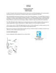
ENGINE
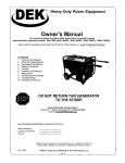
COMPONENTS
Please familiarize yourself with the locations and functions of the various components
and controls of the engine portion of the snow thrower.
9
10
(1) Recoil Starter Handle- Pull-cord for starting
engine.
(2) Throttle Lever- Use to control engine speed.
This should be set to the highest speed when using
the snow thrower.
(3) Fuel Valve Lever- Controls flow of fuel into the
engine.
(4) Choke Lever- Adjusts the amount of air let into
the engine.
(5) Spark plug- Provides proper engine ignition.
(6) ExhaustOutlet for air from engine combustion.
(7) Air cleaner- a removable, cleanable element that
limits the amount of dirt pulled into the engfue.
(8) Fuel Cap- Access to the fuel tank for addfug fuel.
(9) Fuel Tank- Stores gas used to run engine.
(10) On/Off Switch- Used to start/stop engine.
(11) Oil Fill and Dipstick- Location for checking and
filling engine oil.
(12) Oil Drain Plug- Location for draining engine oil.
ASSEMBLY
In order to best protect the snow thrower while in the package, this product comes with
some components disassembled.
Please complete the following assembly steps before
proceeding to use the snow thrower. For ease of assembly, we recommend attaching the
components in the order listed in this manual.
If after
please
Chute
reading
call (888)
this section,
315-3080
you
are unsure
M-F
8-5
about
CT for
how to perform
customer
any of the steps
service
Assembly
To attach the chute to the snow thrower:
1. Mount the chute to the snow output port on the snow thrower as shown in figure
1.
2. Place one of the brackets underneath the chute with the raised groove of the
bracket facing up (see figure la). Line up the holes in the bracket with the holes at
the base of the chute.
3.
4.
Attach the bracket to the chute using two bolts and two nuts as shown in figure
lb..
Repeat steps 2 and 3 for the remaining two brackets.
a
b
Figure
Handle
1- Chute
Assembly
Assembly
Attach the handle to the snow thrower body using the two handle brackets and four bolts
as shown in figure 2. Each side of the handle will require one bracket and two bolts. The
upper hole with bracket on each side requires a long bolt. The lower hole requires a short
bolt with washer.
NOTE: For easiestassembly,we recommendnot attachingthelower bolt of eachhandle
bracketuntil after assemblingthe chuterotationhandle,augeranddrive handlecables,
anddrive speedcontrollever.
Figure 2- Handle Assembly
Attaching
Drive
Speed
Control
Lever
To attach the drive speed control lever, slide it through the drive speed selection hole in
the handle and attach it at the base of the snow thrower using two bolts and two nuts as
shown in figure 3. Do not worry about the position of the handle in the drive speed
selection hole. It will naturally be correct.
b
Figure
3- Drive Speed
Control
10
Lever
Attachment
Chute
Rotation
Handle
To attach the chute rotation handle:
1. Remove the handle grip from the handle by removing the screw at the end (see
figure 4).
2. Slide the end of the chute rotation handle, with the grip removed, through the eye
hole on the snow thrower handle as shown in figure 4 a.
3. Slide the other end of the chute rotation handle through the hole near the base of
the chute. Line the spiral of the handle up with the grooves in the base of the
chute (see figure 4b)..
4. Insert the fastener pin through the end of the chute rotation handle near the chute.
Bend the ends of the pin to hold the pin in place.
5. Reattach the grip to the chute rotation handle.
HOLE
HANDLE
_DLE
GRIP
b
Figure 4- Chute Rotation Handle Assembly
Drive
Control
and Auger
Control
('able
Assembly
The cables that control the drive and auger are already attached to the snow thrower.
connect them to their respective handles:
To
1. Attach the cable hooks to the holes on the inner portion of the drive control and
auger control handles as shown in figure 5a. The hook should dangle freely from
the handles.
2. Connect the drive control and auger control cables to the cable hooks using the
attached turnbuckles (see figure 5b). Rotate the turnbuckles to tighten. The
cables should be just barely taut when the drive and auger control handles are in
the raised position.
11
NOTE: When attaching the cables, be sure they are properly threaded through the main
handle. The auger control cable should fit through the hole next to the speed selector.
The drive control cable should fit in the handle groove on the other side of the speed
selector.
C
b
Figure
5- Cable
12
attachment
TIGHTEN
PREPARING
THE SNOW THROWER
FOR USE
_
The following section describes steps you must follow to prepare the snow thrower
for use. If after reading this section, you are unsure about how to perform any of the
steps please call (888) 315-3080
M-F 8-5 CT for customer service. Failure
perform these steps properly can damage the snow thrower or shorten its life.
Visually
Inspect
the Snow
to
Thrower
Before using the snow thrower for the first time, be sure that the machine is properly
assembled (see the "Assembly" section of this manual). Check that all parts are properly
attached and free from damage. If you are unsure about the assembly or condition of any
of the snow thrower parts, call the customer help line for service.
Before each use of the snow thrower, check the snow thrower for damaged or missing
components.
If parts are damaged or missing, do not attempt to use the machine.
Instead, call our customer help line.
Check
Tire Inflation
Before each use of the snow thrower, check the tire pressure. The pressure of the two
tires should be equal and in the range of 20-24 PSI for each tire to ensure the best
performance.
The pressure can be checked using an ordinary tire pressure gauge. Fill the tires using a
portable air compressor or other compressed air source. NOTE: Do not over-inflate the
tires. For more detail about how to check the tire pressure and fill the tires, see the
Maintenance section of this manual.
Add/Check
Oil
If this is' your first
time using
this snow
thrower:
The snow thrower requires engine oil to operate properly.
from the package, contains 17ooil in the engine crankcase.
thrower for the first time, follow these steps:
The snow thrower, when new
To add oil to your snow
1. Make sure the snow thrower is fully assembled and on a level surface.
2. Unscrew the oil filler cap from the engine crankcase as shown in figure 6.
3. Using a funnel, add approximately 21 fluid oz. of motor oil. Use a regular car
motor oil that performs well in cold conditions. The temperature conditions and
recommended oil grade will vary by geographic area.
4. Wipe the dipstick attached to the oil filler cap with a clean dry cloth. Now replace
the cap.
13
5.
6.
Remove the oil filler cap again and inspect the attached dipstick. Oil should now
be visible on the stick. Ifoil is not visible on the stick, you may need to add more
oil and repeat steps 4 and 5.
Replace the oil filler cap and screw tightly.
NOTE: Even if you have previously measured 21 ounces ofoil, some spillage is
common when adding oil to the crankcase. Always ensure that the engine has
sufficient oil by checking the dipstick. See Figure 6 for proper oil level.
,9399U
J::IV3J
Figure
5- Removing
If this is not your first
oil filler cap
time using
the snow
Figure 6- Proper
oil level
thrower."
Before each use, you should check the oil level in the snow thrower:
1. Unscrew the oil filler cap and wipe the dipstick with a clean dry cloth. Now
replace the cap.
Remove the oil filler cap again and inspect the attached dipstick. Oil should now
be visible on the stick. Ifoil is not visible on the stick, you may need to add more
oil and repeat these steps to check the proper oil level.
Once you have ensured the engine oil level is correct, replace the oil filler cap and
screw tightly.
.
.
Add/Check
Gasoline
A WARNING:
Gasoline
and gas fumes are highly flammable.
•
Do not fill tank near an open flame.
•
Do not overfill. Always check for fuel spills.
To ensure that the snow thrower runs smoothly, use only FRESH, U_NLEADED GAS
WITH AN OCTANE RATING OF 87 OR HIGHER. To add gasoline:
1. Make sure the snow thrower is turned off and situated on a level surface.
2. Unscrew gas cap and set aside (NOTE: the gas cap may be tight and hard to
unscrew).
3. Slowly add unleaded gasoline to the fuel tank. The snow thrower fuel tank when
new from the package is empty. The capacity of the fuel tank is 0.95 Gallons. BE
CAREFUL NOT TO OVERFILL. Do not fill the gas tank to the very top.
4. Replace fuel cap and wipe up any spilled gasoline with a dry cloth.
14
IMPORTANT:
• Never use an oil/gasoline mixture.
• Never use old gas.
• Avoid getting dirt or water in the fuel tank.
• Gas can age in the tank and make it hard to start up the snow thrower in the
future. Never store the snow thrower for extended periods of time with fuel in the
tank.
Adjust
Skid
Shoes
Adjustment of the skid shoes governs the height above the ground at which the auger
shield operates.
For clearing snow from concrete, asphalt, and other smooth surfaces, it is best to set the
auger shield so that the bottom of the shield scrapes the ground.
For clearing snow from gravel, dirt, and other rough surfaces, it is best to set the auger
shield slightly above the ground to avoid dirt and gravel from entering the auger.
The optimal height of the shield will vary depending on the type of surface being cleared.
Surfaces with larger gravel or stones would require a more raised auger shield.
To adjust the skid shoes:
1. Make sure the snow thrower is on a solid, smooth, and level surface.
2. Place a spacer board on the ground underneath the auger shield between the skid
shoes. The thickness of the board should be the same as the height above the
ground you wish to raise the auger shield to. The skid shoes should not touch the
board (see figure 7).
3. Using a wrench, loosen the four nuts located on the skid shoes (2 nuts on each
skid shoe) and allow the skid shoes to slide to the ground.
4. Re-tighten the nuts on the skid shoes and wheel the snow thrower off of the
spacer board
A_UST
SKID SHOf
SPACER
BOARD
Figure
7- Adjusting
15
Skid Shoes
OPERATION
_
Before starting the snow thrower, make sure you have read and performed the
steps in the "Preparing
the Snow Thrower for Use" section of this manual. If you are
unsure about how to perform
3080
Starting
M-F
any of the steps in this manual please call (888)
8-5 CT for customer
the Snow
315-
service.
Thrower
To start up the snow thrower, perform the following
steps:
1. Turn the engine fuel valve lever to the "on" position (see figure 8).
2. Move the choke lever to the closed position as shown in figure 7 (NOTE: If you
have just been using the snow thrower and the engine is still warm, keep the
choke in the "open" position).
3. Move the engine throttle lever to the last position (see figure 8).
4. Move the engine switch to the "on" position as shown in figure 9.
CHOKE
Figure 8 Engine lever positions
ENGINE
SWITCH
ON
Figure 9- Engine switch positions
16
5.
6.
7.
Pull on the recoil starter handle slowly until a slight resistance is felt (see figure
10) then pull quickly to start the engine. Return cord gently into the machine.
Never allow the cord to snap back.
If engine fails to start, repeat step 5. NOTE: After repeated attempts to start the
engine, please consult the troubleshooting
guide before attempting again. If
problems persist please call (888) 315-3080 M-F 8-5 CT.
Once the engine has started and run for about a minute, move the choke lever
about halfway towards the "open" position. Wait another 30 seconds and then
move the choke lever all the way to the "open" position.
NOTE: Allow the snow thrower to run outdoors
use the machine.
Figure
Using the Snow
10- Pulling
for several minutes before attempting
the recoil starter
to
handle
Thrower
Once the snow thrower has been running outside for several minutes, it is now ready for
use. To use the snow thrower:
1. Make sure the path in front of the snow thrower is free from people, animals,
objects, and all other obstructions except for snow.
2. Adjust the chute outlet to the desired direction. Turn the chute rotation handle
clockwise or counter-clockwise
until the desired position is reached (see figure
11).
IMPORTANT:
Never direct the chute outlet toward people or animals. While
snow may seem harmless, it can contain rocks or other debris that can cause
serious injury when projected through the chute.
3.
4.
5.
6.
Move the drive speed control lever to the desired speed. There are seven speedsfive forward speeds and two reverse speeds. 1 is the slowest forward speed and 5
is the fastest forward speed. R1 is the slowest reverse speed and R2 is the fastest
reverse speed (see figure 12). NOTE: There is no neutral drive setting.
Press down on the auger control handle. The auger should start spinning.
Press down on the drive control handle. The machine should start moving in the
direction and speed selected with the drive speed control lever.
When you have finished clearing the ilmnediate snow path, release the auger
control handle and the drive control handle.
17
You can adjust the drive speed and direction using the drive speed control lever. Be
sure to release both the auger control handle and the drive control handle before
adjusting the drive speed control lever.
As you use the snow thrower, you may want to adjust the chute outlet direction. Be
sure to release both the auger control handle and the drive control handle before
adjusting the chute outlet direction.
Figure
11- Adjusting
Chute
Outlet
Direction
Figure
12- Adjusting
Drive Speed
and Direction
CHUTE DEFLECTOR
The angle of the chute deflector controls the throwing distance of the snow leaving the
chute. Raising the angle will increase the throwing distance. Lowering the angle will
decrease the throwing distance (see figure 13).
To adjust the chute deflector:
1. Make sure the engine is stopped and the auger and impeller have come to a full
stop.
2. Loosen the knobs on the chute deflector as shown in figure 13 and adjust the
chute deflector to the desired angle.
3. Re-tighten the knobs on the chute deflector. Do not over-tighten.
increase
throwing_
distance _1_
decrease
throwing
distance
ustment
Figure 13- Adjusting the chute deflector
18
STOPPING
THE SNOW THROWER
When you are finished using the snow thrower, perform the following
steps to shut it
down:
1. Move the snow thrower away from any snow piles.
2. Run the auger and impeller for 30 seconds to clear any remaining snow inside the
snow thrower.
Set the engine switch to the "off' position. This will stop the motor.
4. Move the fuel valve lever to the "off' position.
5. Dust snow off of all snow thrower surfaces.
.
WARNING:
Allow the snow thrower to cool for several
areas that become hot during use.
minutes
before touching
CAUTION:
Allowing gas to sit in the snow thrower fuel tank for long periods of
time without use can make it difficult to start the snow thrower in the future. Never
store snow thrower for extended periods of time with fuel in the tank.
STORAGE
A CAUTION:
is still hot.
/ TRANSPORT
PROCEDURES
Never place any type of storage cover on the snow thrower while it
When transporting or storing your snow thrower for extended periods of time:
• Empty the gas tank (see "Emptying the Gas Tank" in the "Maintenance"
section).
• Disconnect the spark plug.
• Do not obstruct any ventilation openings.
• Keep the snow thrower in a cool dry area.
19
MAINTENANCE/CARE
Proper routine maintenance of the snow thrower will help prolong its life. Please
perform maintenance checks and operations according the schedule in figure 14.
If you have questions about any of the maintenance
please call (888) 315-3080 M-F 8-5CT.
procedures
CAUTION:
running.
while the snow thrower
Never perform
Recommended
operations
Function
Frequency
Clear jams
As necessary
Before each use
Engine Oil
check pressure
check level
Air Filter
replace
check
Every 50 hours or as needed
Every 10 hours
clean
Every 50 hours or as needed
Spark Plug
Gas Tank
Before each use
check/clean
Every 100 hours
Before each use
check gas level
Empty
Drive and
Auger Cables Adjust tension
Shear Pins
Before storing for extended time
As necessary
Replace
When broken
Figure 14- Recommended
('leaning
the Snow
TIMELINE:
is
Maintenance Schedule
Mechanism
Auger and
Impeller
Tires
maintenance
listed in this manual,
maintenance schedule
Thrower
When dirty.
To clean the snow thrower, use a damp cloth and mild detergent on the surfaces only.
Never get soap or water inside the working mechanisms of the snow thrower.
NOTE: Do not clean with water when the snow thrower is cold from being outdoors
may cause water to freeze onto the machine and damage it.
20
as it
Clearing
Auger
or Impeller
Jams
A WARNING: The auger and impeller rotate at fast speeds that can cause damage
or even amputation to body parts. Even if you do not see the auger or impeller
rotating, they may start at any time if the engine is running.
• Always turn off the engine before attempting to clear any clogs or jams.
• Keep hands and feet away from rotating parts while the engine is running.
• Do not wear loose fitting clothing that can become entangled in rotating parts.
To clear a jam in the auger or impeller:
1. Turn off the snow thrower engine
2. Wait until the auger and compeller have come to a full stop.
3. Clear any visible jams using a long stick or broom handle. DO NOT try to clear
jams with your hands or feet.
4. If the jam is too difficult to clear, do not force it out. Call the customer service
line at (888) 315-3080.
Checking
TIMELINE:
Tire Pressure
Before each use for best performance.
To get the best performance from
equal and in the range of 20 to 24
nozzle cap and attach an ordinary
inflate using an air compressor or
1NFLATE.
your snow thrower, the pressure in the tires should be
PSI. To check the tire pressure, unscrew the inflation
tire pressure gauge as shown in figure 15. If needed,
other compressed air source. DO NOT OVER-
Figure 15- Checking tire pressure
CheeMng/
TIMELINE:
Adding
Oil
Before each use, you should check the oil level in the snow thrower:
1. Unscrew the oil filler cap and wipe the dipstick with a
Now replace the cap.
2. Remove the oil filler cap again and inspect the attached
be visible on the stick. Ifoil is not visible on the stick,
oil and repeat these steps to check the proper oil level.
21
clean dry cloth (figure 16).
dipstick. Oil should now
you may need to add more
Use a regular car motor oil
.
that performs well in cold conditions. The telnperamre conditions and
recommended oil grade will vary by geographic area.
Once you have ensured the engine oil level is correct, replace the oil filler cap and
screw tightly.
Figure
Rephtcing
TIMELINE:
when dirty.
16- Removing
oil filler
cap
Figure
17- Proper
oil level
the Oil
You should drain and replace the oil in the crankcase
every 50 hours or
To drain the oil from the crankcase:
1. Place a bucket near the engine to catch oil as it drains.
2. Using a wrench, unscrew the oil drain plug. The oil drain plug is located just
below and to the left of the oil filler cap as shown in figure 18. Allow all the oil
to drain from the crankcase.
3. Replace the oil drain plug and tighten with the hex wrench.
Figure
18- Draining
22
the oil
After you have drained the dirty oil, refill the crankcase with fresh auto motor oil. To fill
the crankcase, perform the steps listed in the "Checking/Adding
Oil" portion of this
MAINTENANCE
section.
NOTE:
your
Never
local
Air Filter
dispose
recycling
of used
center
motor
or auto
oil in the trash
garage
to arrange
or down
a drain.
Please
call
oil disposal.
Maintenance
TIMELINE:
Clean the air filter every 50 hours or more often in dirty environments.
To clean the air filter:
1. Unscrew the wing nut from the top of the air filter and remove the plastic case
(see figure 19).
2. Unscrew the wing nut that holds the metal air filter bracket to the machine.
Remove the metal bracket with sponge attached.
3. Slide the sponge element off of the metal bracket. Wash the sponge element in
household detergent and warm water. Allow to dry.
4. Soak the dry element in engine oil. Squeeze out any excess oil.
5. Tap the metal bracket, with paper air filter inside, against a hard surface to knock
out any dirt.
6. Slide the sponge element back onto the metal bracket.
7. Replace the metal bracket and secure with the inner wing nut. Then replace the
plastic cover and secure with the outer wing nut.
@
Figure
19- Removing
23
the air filter
Spark
Plug Maintenance
TIMELINE:
Every 100 hours or as needed.
The spark plug is important for proper engine operation. A good spark plug should be
intact, free of deposits, and properly gapped. To inspect your spark plug:
1. Pull on the spark plug cap to remove it.
2. Unscrew the spark plug from the engine using the spark plug wrench included
with this product (see figure 20).
3. Visually inspect the spark plug. If it is cracked or chipped, discard and replace
with a new spark plug. Measure the plug gap with a gauge (see figure 21). The
gap should be 0.7-0.8ram (0.028-0.03 lin).
4.
5.
If you are re-using the spark plug, use a wire brush to clean any dirt from around
the spark plug base and then re-gap the spark plug.
Screw the spark plug back into its place on the engine using the spark plug
wrench. Replace the spark plug cap.
Figure 20- Removing the spark plug
Emptying
TIMELINE:
Figure 21- Measuring
the spark plug gap
the Gas Tank
Before
storing
the snow
thrower
for extended
periods
of time.
To drain the snow thrower engine of gas:
1. Make sure the engine is turned off.
2. Place a gas safe container under the carburetor (see the "Snow Thrower Parts
Diagram" to reference this part).
3. Move the fuel valve lever to the "on" position.
4. Unscrew the outward facing bolt from the bottom of the carburetor (see figure
22). Gas should start to empty from this point.
5. Catch the emptying gas in the gas safe container until all the gas has drained.
6. Turn the fuel valve to the "off' position.
24
7.
8.
Replace the bolt on the carburetor.
Store the emptied gasoline in a suitable place.
_k CAUTION:
Do not store
A[k CAUTION:
Never
authorities
to dispose
pour
TIMELINE:
Drh,e
one season
down
a drain
to another.
or in a gutter.
Call your
local
of gas properly.
Figure
Adjusdng
fuel from
gasoline
and Auger
22- Draining
gas from the carburetor
Cables
As needed.
Over time, the tension in the cables that lead to the drive control and auger control
handles may loosen. Ideally, the cables should be just barely taught when the handles
are in the released position. To tighten the handle cables, use a wrench or pliers and
gently rotate the metal turnbuckle at the top of the cable until the desired tension is
achieved (see figure 23).
/_
Figure
23- Adjusting
T|GHTEH
drive and auger cable tension
25
Replacing
Shear
Pins
A WARNING: The auger and impeller rotate at fast speeds that can cause
damage or even amputation to body parts. Even if you do not see the auger or
impeller rotating, they may start at any time if the engine is running.
•
Always turn off the engine before attempting to clear any clogs or jams.
•
Keep hands and feet away from rotating parts while the engine is running.
Do not wear loose fitting clothing that can become entangled in rotating
parts.
TIMELINE:
When Broken
The snow thrower contains two shear pins, one on each end of the auger shaft as
shown in figure 24. A clog or jam in the auger may cause one or both of the shear
pins to break. This is a safety mechanism to protect the rest of the snow thrower from
overload and damage. The snow thrower comes with two replacement shear pins. To
order more shear pins, please call our customer service line.
To replace a shear pin:
1. Turn off the engine and wait for all moving parts to come to a complete
2.
3.
stop.
Remove any remnants of the broken shear pin. You may need to unscrew the nut
from the broken shear pin.
Place a new shear pin through the hole in the auger shaft and tighten using the
shear pin nut.
Figure 24- Replacing the shear pin
26
SPECIFICATIONS
Snow
Thrower
Clearing Width
Throwing Distance
22 Inches
Max. 50 feet
Chute Rotation
180 degrees
Wheel
Pneumatic,
Drive Speeds
Dimensions
Forward: 0.9, 1.2, 1.5, 1.8, 2.5 MPH
Reverse: 0.9, 1.2 MPH
L= 35.5" W = 24.5" H = 31.5"
Dry Mass
158 Lbs
tubeless,
size 4.10-6 N.H.S.
Engine
Engine Type
Ignition System
4-Stroke OHV Single Cylinder
Non-Contact Transistor
Fuel Tank Capacity
Crankcase oil capacity
0.95 Gallons
21.1 Fluid Ounces
TROUBLESHOOTING
IMPORTANT:
M-F 8-5.
Problem
If trouble
persists
please
Cause
call our customer
help line at (888)
315-3080
Solution
Engine will not
Engine switch is set
start or runs poorly Lo"off".
Set engine switch to "on".
Fuel valve lever is
set to "closed".
Move the fuel valve lever to "open" position.
Close the choke.
Shoke is open.
Engine is out of gas. Add gas.
Engine is filled with
sontaminated or old
gas
Change the gas in the engine.
Spark plug is dirty.
Spark plug is
3roken.
Snow thrower is not
3n level surface,
Clean spark plug.
Oil is low
Add or replace oil.
Replace spark plug.
Move snow thrower to a level surface to prevent low oil
shutdown from triggering.
27
Auger or impeller
does not rotate
_,uger drive handle
s not depressed
_,uger drive handle
sable is loose
Foreign substance
slogging auger or
mpeller
Depress auger drive handle
Adjust tension in cable
Turn off machine and unclog auger or impeller
Shear pin broken
Replace shear pin.
Belt broken or loose Call customer service
Snow is not thrown
or not thrown very Impeller or chute is
far
slogged
Turn off engine and unclog.
Shute deflector is
set too low
Adjust chute deflector angle.
Snow thrower will
not drive or drives Drive handle is not
poorly
depressed
Depress drive handle
Drive handle cable is
oose
Adjust cable tension
Speed is not
Engage the speed selector handle to one of the seven
3roperly engaged
speeds.
Tire inflation is poor Inflate tires.
Tire pins are not
engaged
Check the pins that hold the wheels to the drive axle.
2g
9
8
r_
\
6
79
36
/
/
10
i4
100
÷
\
\
99
b_
\
!05
9O
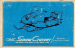
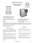
SNOW
THROWER
PARTS
Part #
Part Description
1
_andle assembly
2
_uger and chive conr_ot handles
3
LIST
Quantity
Part #
Part Description
Quantity
56
8 lmll Flax washer
3
2
57
M8 x 20 Hex screws
1
_ubber cap
2
58
l"_nslmssion
1
4
_8x50
4
59
_tlley motmt1_
5
_8 hex imts
35
60
transmission
6
Ftmlbuckte
2
61
Deep Groove Bearing
1set
He..: scre'_ s
piffle5,
plate
1
p_llle5, shaft
1
2
2able
2
62
_pa_er bi_hing
1
8
_peed co1_tml frame
1
63
_fltey _a_ket
1set
9
_6x35
Hex screw
5
64
angle plate
10
)rive Speed Control Lex er
1
65
_hift arm
11
_teel bracket
1
66
M8x40 Hex screws
1
12
_6x30
1
67
Spacer
1
13
_ye bolt
1
68
Large Pulley
1
14
_lbber ring
1
69
fiat key
1
15
,_asher
2
70
_lmd co_ _r
1
16
_ing-pin
2
71
_ph_rical bearing
1
17
_ex screws
3
72
Hex screws
1
18
2hain Wheel
3
73
Spring 1
1
19
mite.',' molmting
1
74
mottntlng plate
2O
_6x10
23
75
Large tension wheel assy With bearing
21
xtlley molmting
1
76
Spacer
1
22
_neluna_ic Tire
2
77
Clmte
1
23
_ey
2
78
Cln_e deflector
24
_arge Gear
1
79
Cln_te deflector
25
_d cap bushing
2
80
_afety bar assy
26
hivin_
1
81
_pring-3
1
27
?in
1
82
Clmte Mortaring "_,Va
sher
3
28
i ansmlssion
1
83
Plastic Cover
1
29
51ran flax washer
27
84
M6 Hex nu_
26
30
21rote rotation handle grip
1
85
C-shaped
31
"ockei
1
86
M6x 15 square-necked
32
_oly-ring
1
87
Auger Shield
33
_teel Motmtlng
1
88
Skid Shoe
2
34
\¢8x20 square neck screws
4
89
M8x25 square neck scows
10
35
aasher
2
90
Long blade
36
mglne
1
91
Fan Assen_ly
37
_Theel Cover
1
92
Washer
1
38
_mall tension bracket
1
93
Pm
2
39
He..: scre'_ s
plate-1
Hex scre'_ s
plate-3
shaft
case cover
Plate
?ace1
1
1 set
1
1 set
1
knob
1
1 set
plate
1
scre'_
5
1 set
1
1 set
1
94
l"lmlst Bea_ing
1
4O
_pring 5
1
95
Deep Groove Bearing
1
41
xl_hing-2
1
96
Drive Worm
1
42
mlall tensioning
1 set
97
Bearing
1
43
_pacer
2
98
Pdght A_lger
1
44
\Cain pulley
1
99
M6x20 Hex screws
10
45
_:-Belt
1
100
Upper Worm Case
1
46
_:-Belt
1
101
Worm Gear
1
47
Fransmission
1
102
Lower worm case
1
48
\¢10 Hex mlts
2
103
_ltl)_lt shaft bushing
1
49
10 iron Flat washei
1
104
Drive Shaft Bushing
4
5O
)ear-Wheel
Cox er with bearing
2 sets
105
_ivmg
1
51
)ear-Wheel
Washel
2
106
Left Auger
52
albbei ring
2
107
Shaft Bushing
1
53
)ear-Wheel
1
108
Bearing end cup
2
54
Aex Gear-shaft
1
109
Seal
55
leep groox e bearing
2
1t 0
_hear bolts
wheel wi bearing
case
30
sh_
1
1
2 sets
@
@
ENGINE
PART
#
PARTS LIST
PART DESCRIPTION
PART
QTY
1
_LANGE BOLT ( M6'12
2
_EAD COVER
3
_tEAD COVER
4
BREATHER
5
_IVOT ADJUSTING
6
ROCKER AR_M PIVOT
7
#
QTY
PART DESCRIPTION
1
12
52
_'ARBURETOR
COMP
1
53
_'ARBURETOR
PACKING
1
54
2HOKE
1
55
2ARBURETOR
SPACER
2
56
a_IR CLEANER
ELBOW COMP
2
57
FLANGE NUT ( M6 )
ROCKER AK\I
2
58
FLANGE BOLT ( M6'20
8
_IVOT BOLT ( M8 )
2
59
ELBOW GASKET
1
9
VALVE
1
60
SILENCER
1
1
61
hIR FILTER
ELEMENT
1
62
adR FILTER
GROMMET
BRACKET
COVER
)
TUBE
NUT
ROTATOR
PAPER
GASKET
1
LEVER
1
COMP
COMP
1
1
5
1
)
NOSE
1
10
N VALVE
11
EX VALVE
12
VALVE
2
63
hiP. FILTER
13
gUSH ROD GUIDE PLATE
1
64
a_IR FILTER
14
_LANGE BOLT ( M8'58
4
65
hiP. FILTER
15
_'YLFNDER HEAD
1
66
\,IUFFLER
16
EXHAUST PIPE STUD BOLT
2
67
FLANGE NUT ( M8 )
2
17
SPARK PLUG ( LD NGK )
1
68
\,IUFFLER
1
18
2ARBURETOR
2
69
YAPPING SCREW
( M5'8
19
2YIFNDER
1
70
\,IUFFLER
PROTECTOR
20
DOWELPIN
2
71
_'RANKSHAFT
21
VALVE
1
72
PLAIN KEY
22
EX VALVE
1
73
_'ASE COVER
23
2AMSHAFT
ASSY
1
74
DOWEL PFN ( 8"i4 )
24
3ISTON RING SET
1
75
_'IL4NKCASE
25
)USH ROD
2
76
DIL FITLER
CAP GASKET
2
26
_'ALVE LIFTER
2
77
DIL FILLER
CAP
2
27
_ISTON PIN
1
78
FLANGE BOLT ( M8'28
28
_ISTON PIN CLIP ( 18rim1 )
2
79
SLIDER SHAFT
1
29
_tSTON
1
80
PLAIN WASHER
1
30
_'ON_ECTING
1
81
3OVERNDR
GEAR ASSV
1
31
DRAIN PLUG BOLT
2
82
30VEKNOR
HOLDER
CLIP
1
32
DRAIN PELTLIWASHER
2
83
PHRUST WASHER
( 61ran )
1
33
BATL BEARING
2
84
30VERNOR
34
PRANK CASE
1
85
ROCKER
35
GNITIDN
COIL ASSY
1
86
LOCK PIN ( 81ran )
1
BOLT ( M6'25
2
87
PUBE CLIP
2
1
SPRING
RETAINER
SPRING
RETAINER
SPRING
)
COMP
STErD BOLT
HEAD
GASKET
( 10"16 )
ROD ASSY
( 10 21ran )
( 6205 )
1
WFNGNUT
1
COVER
WINONUT
1
1
GASKET
COMP
OUTER
1
)
4
1
1
COMP
1
1
PACKING
COVER
2
ASSY
)
1
6
1
SLIDER
1
36
:LANGE
37
DIL SEAL ( 25"41 25*6
2
88
FUEL TU13E
38
_'LYWHEEL CDMP
1
89
FLANGE BOLT ( M6'30
39
SEMICIRCLE
1
90
FUEL TANK JOINT
1
40
POOLING
1
91
D-RING ( 14nm_ )
1
41
STARTER PLIIEY
1
92
FUEL TANK COMP
1
42
8HROLX)
1
93
FUEL FILTER
1
43
:LYWHEEL
NUT
1
94
FUEL FILTER
44
:LYWHEEL
SIDE PLATE
1
95
FUEL CAP
)
)
KEY
FAN
32
)
CAP PACKING
1
1
1
1
96
E'ONTROL ASSY
1
97
£HROTTLE
ENGINE STOP SWITCH ASSY
1
98
3OVERNOR
ROD
1
_COIL
1
99
_O\7EI_NOR
SPRING
]
3
100
.)UADRATE
BOLT ( M6 )
1
1
101
2ONTROL
45
_'LANGE BOLT ( M6'16
46
:AN COVER
47
48
49
_'LANGE BOLT ( M6'8
50
._TAKE PIPE GASKET
51
2ARBETRETOR
)
COMP
STARTER
ASSY
)
INSULATING
PLATE
1
33
RETURN
ARM
1
SPRLNG
1
1
LIMITED WARRANTY FOR YARDWORKS _'s_
SNOW THROWER
Remember
to save your receipt and to accurately
fill out and mail your product
card. You must provide proof of purchase for all warranty
work.
This Yardworks
workmanship
": snow
thrower
for a period
is warranted
to be free from defects
of two (2) year from date of original
is used for Commercial
or Rental
original purchase.
Keep purchase
in materials
purchase.
registration
and
If this snow
thrower
purposes,
it has a warranty period of 90 days from date of
receipt and mail in the product registration
card for proof of
purchase.
Yardworks _R:
will repair or replace, at its discretion, any part that is proven to be defective in
materials or workmanship under normal use during the two (2) year warranty period.
Warranty repairs or replacements will be made without charge for parts or labor. Parts
replaced during warranty repairs will be considered as part of the original product and will
have the same warranty period as the original product.
To exercise the warranty, DO NOT RETURN TO RETAILER.
Instead, call the toll free
Customer Service number: (888) 315-3080 and you will be instructed on where to take the
snow thrower for warranty service. Take the snow thrower and proof of purchase (your
receipt) to the repair facility recommended
by the Customer Service Representative.
The warranty does not extend to snow throwers damaged or affected by accidents, neglect,
misuse, unauthorized alterations, use in an application for which the product was not designed
and any other modifications or abuse.
Yardworks :R:is not liable for any indirect, incidental or consequential damages from the sale
or use of this product. Any implied warranties are limited to two (2) year as stated in this
written limited warranty. Some states do not allow the exclusion or limitation of incidental or
consequential damages. Some states do not allow limitation on the length of an implied
warranty. This warranty gives you specific legal rights, and you may have other rights that
vary from state to state.
Yardworks
_s_PO Box 1110.
34
Dundee,
IL 60118