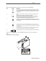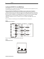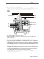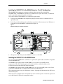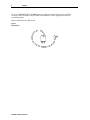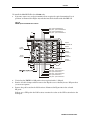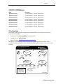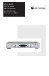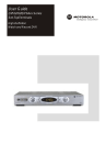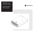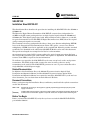
1
STARLINE® SG2-DRT-3X Installation Sheet 522120-001 This Installation Sheet describes the procedure for installing the SG2-DRT-3X in the SG2440 or SG2000 node. The Motorola® Digital Return Transmitter (SG2-DRT-3X) converts three independent 5 to 42 MHz analog RF return-path signals into one digital optical signal within the SG2000 and SG2440 nodes. This digital optical signal, with 10-bit resolution and 3.1 Gbps rate, is suitable for optical transmission to the GX2-DRR-3X Digital Return Receiver (DRR) where the original analog return-path signals are recreated. The transmitter is factory-configured with either a dense wave division multiplexing (DWDM) laser on the International Telecommunications Union (ITU) grid or a coarse wave division multiplexing (CWDM) laser that is applicable to the required link. Motorola provides standard models that are identified in the subsection SG2-DRT-3X Models at the end of this document. The specific wavelengths are stamped on the label of each transmitter. An automatic power control (APC) system regulates the optical output power from the laser. The unit provides automatic gain control (AGC) and requires no adjustment. The SG2-DRT-3X features alarm LEDs to report local status information. To facilitate easy upgrades, the SG2-DRT-3X has the same set-up levels as the analog return transmitters. The double-wide module occupies the same locations as the two analog transmitters in the node lid. The SG2-DRT-3X generates its own 5 V power and works with a single SG2-PS2 or SG2-PS power supply. Related Documentation In addition to this Installation Sheet, the SG2440 Telecommunications Optical Node Installation and Operation Manual and the SG2000 Telecommunications Optical Node Installation and Operation Manual are required to install the SG2-DRT-3X. If you do not have these documents, you can obtain them from the Motorola Web site. Document Conventions Before you begin using this Installation Sheet, familiarize yourself with the stylistic conventions used in this document: SMALL CAPS Denotes silk-screening on the equipment, typically representing input/output (I/O) and power supply connections * (asterisk) Indicates that several versions of the same model number exist and the information applies to all models; when the information applies to a specific model, the complete model number is given Before You Begin Before you install the SG2-DRT-3X, verify that you have received the SG2-DRT-3X-CH*Kit, part number 498284-*. SG2-DRT-3X Installation Sheet 2 STARLINE Figure 1 illustrates a block diagram of the SG2-DRT-3X. Figure 1 SG2-DRT-3X block diagram LF pilot generator Filter and clock driver 5-42 MHz 42 MHz LPF Frame synchronization A/D converter Gain block Pin attenuator Laser driver ITU laser RF detector LF pilot generator 5-42 MHz 42 MHz LPF A/D converter Pin attenuator 32:1 multiplexer 3.1 GHz xoscillator Gain block RF detector LF pilot generator Microprocessor 5-42 MHz 42 MHz LPF A/D converter Pin attenuator Gain block ADC in DAC out RF detector Figure 2 illustrates a top view of the SG2-DRT-3X. Figure 2 SG2-DRT-3X transmitter 1 OPTICAL POWER (1 V/mW) 2 F A U L T 3 4 I N P U T I N P U T A B SG2-DRT-3X O N Digital Return Optical Transmitter ALARM XXXXXX-XXX-XX ITU/CH XX WAV XXXX.XX XXXXXXXXXXX 5 SG2-DRT-3X Installation Sheet STARLINE Table 1 provides information on the user-related features of the SG2-DRT-3X. Key Feature Description 1 2 OPTICAL POWER (1 V/mW) F A U L T O N ALARM 3 I N P U T This test point enables monitoring of the optical output level of the module. The nominal scale factor is 1.0 V/mW (6.3 V equates to 8 dBm). The optical power test point does not track changes in optical power due to the laser tracking error. A red (FAULT) LED indicates that the laser output power is below normal limits. A green LED (ON) indicates the transmitter is enabled. Because the laser output requires a short period of time to stabilize, it is normal for neither LED to illuminate for approximately 10 seconds. The module must be enabled for the fault indicator to function. This MCX connector provides the SG2-DRT-3X with channel A RF input through a cable connection to the node lid board in an SG2440 or the E-pack in an SG2000. A 4 I N P U T This MCX connector provides the SG2-DRT-3X with channel B RF input through a cable connection to the node lid board in an SG2440 or the E-pack in an SG2000. Channel C RF input is provided by direct connection of the node lid board with the D-type connector on the bottom of the SG2-DRT-3X. B 5 This SC/APC-type connector provides optical output from the SG2-DRT-3X. Figure 3 illustrates a side view of the SG2-DRT-3X and indicates the laser warning label. Figure 3 SG2-DRT-3X side view and laser warning label DANGER INVISIBLE LASER RADIATION WHEN OPEN PEAK POWER 10 mW CLASS I LASER PRODUCT THIS PRODUCT COMPLIES WITH 21CFR CHAPTER 1 SUBCHAPTER J SG2-DRT-3X Installation Sheet 3 4 STARLINE Installing the SG2-DRT-3X in the SG2440 Node The SG2440 carries each RF return path individually to the lid board and no adjustments to the electronics package (E-pack) are necessary. Before you install the SG2-DRT-3X in the SG2440, you must configure the node with the SG2440 DR-3X board. In this configuration, the RF return signals from RP1 and RP3 are combined and placed onto the D-subconnector beneath the double-wide transmitter module. The RF return signals from RP2 are routed to the MCX connector DRT1. The RF return signals from RP4 are routed to the MCX connector DRT2. RF cables are used to route the signal from DRT1 and DRT2 to the top of the transmitter to RF INPUT A and RF INPUT B respectively. If different combining scenarios are required, you may reconfigure the RF RP cables on the lid board. Figure 4 illustrates a block diagram of the SG2440-DR-3X return configuration. Figure 4 SG2440-DR-3X return configuration E-PACK PLUG-IN BOARD LID XMTR INPUT TX D sub location C RP1 RP3 RP2 DRT1 3.5 dB A (MCX) RP4 DRT2 3.5 dB (MCX) Figure 5 illustrates the SG2440-DR-3X return board. Figure 5 SG2440-DR-3X return board T1 R5 R1 R2 J9 SG2-DRT-3X Installation Sheet R6 R3 R4 B STARLINE 5 To install the SG2-DRT-3X in the SG2440 node: 1 If present, remove any analog transmitter that occupies the optical XMTR B or A positions, as illustrated in Figure 6, and then install the double-wide SG2-DRT-3X. Figure 6 SG2440 lid TP XMTR B Pad XMTR B Return configuration location TP XMTR A Pad XMTR A TP DRT1 Pad DRT1 TP DRT2 Pad DRT2 Optical XMTR B RP1 RP3 RP2 RP4 DRT1 DRT2 Optical XMTR A 2 Replace the XMTR B 15 dB pad with a 5 dB pad. 3 Install the SG2-DRT-3X board in the return configuration location on the lid board as illustrated in Figure 5. 4 Ensure that the PIC cable is properly connected to the lid and E-pack connectors. 5 Install the two RF cables from DRT MCX 1 and DRT MCX 2 to RF INPUT A and RF INPUT B respectively on top of the SG2-DRT-3X. 6 Confirm that the green LED (ON) located on the top panel of the SG2-DRT-3X is illuminated to confirm enable status. A delay of approximately 10 seconds before illumination is normal. 7 Review return-path system levels: Each input of the SG2-DRT-3X is configured to drive the laser to the recommended level of +15 dBmV. Use TP DRT1 and TP DRT2 (Figure 5) to monitor the levels of the segmented ports. Pad DRT1 and pad DRT2 are used to adjust the level into the transmitter. Use TP XMTR B to monitor the levels of the two combined ports. Pad XMTR B is used to adjust the level into the transmitter. SG2-DRT-3X Installation Sheet 6 STARLINE TP XMTR A and Pad XMTR A are not used. It is not necessary to pad the XMTR A location as no signal is present. 8 Close the housing and use a torque wrench to progressively tighten the housing bolts to a final torque of 12 ft-lbs. in the sequence stamped on the housing lid. Figure 7 illustrates a properly installed and cabled SG2-DRT-3X. Figure 7 SG2-DRT-3X installed in SG2440 SG2-DRT-3X Installation Sheet STARLINE 7 Installing the SG2-DRT-3X in the SG2440 Node in a 1X or 2X Configuration The SG2-DRT-3X transmitter can operate with three data streams. If you install the SG2-DRT-3X in an SG2440 that will remain a combined (1X) or split (2X) return, an additional cable is provided to properly load the transmitter. To properly cable the SG2-DRT-3X for a combined or split return: 1 Verify that the SG2440 return configuration plug-in board is either a redundant (1X) or a split (2X) model. 2 Insert the provided cable from the redundant transmitter’s D subconnector into RF INPUT A or INPUT B on the SG2-DRT-3X as illustrated in Figure 8. Figure 8 SG2-DRT-3X cabling for combined configuration 3 Change the 15 dB JXP pad at the XMTR A location to a 5 dB JXP. Installing the SG2-DRT-3X in the SG2000 Node You can equip the SG2000 with a combined or a split-return path module and still be compatible with the SG2-DRT-3X. On SG2000 nodes equipped with an SG2-RPM/C, you can select any two RF ports for segmentation. The two remaining ports will automatically be combined and put on the D subconnector beneath the double-wide transmitter. On SG2000 nodes equipped with an SG2-RPM/S only, you can segment RF ports 1 and 3. Ports 2 and 4 are combined and are automatically put on the D subconnector. The segmented inputs occupy the ICS plug-in location. If equipped, ICS functionality will be lost on these two ports. When the node is equipped with a transponder for status monitoring, Port 1 cannot be segmented as the ICS location is before the transponder output. SG2-DRT-3X Installation Sheet 8 STARLINE To use the SG2-DRT-3X, the SG2000 must be equipped with the ICS plug-in board. The circuitry on this assembly contains 9 dB of attenuation to ensure proper levels into the transmitter input. Figure 9 illustrates the ICS board. Figure 9 SG2 ICS board J1 SG2-DRT-3X Installation Sheet STARLINE 9 To install the SG2-DRT-3X in the SG2000 node: 1 If present, remove any analog transmitter that occupies the optical transmitter B or A positions as illustrated in Figure 10, and then install the double-wide SG2-DRT-3X. Figure 10 SG2000 optical transmitter B and A locations JP1 Pad - optical transmitter B Test point - optical transmitter B Pad - optical transmitter A Test point - optical transmitter A Optical transmitter B Optical transmitter A Power supply 2 Optical receiver C Optical receiver B Power supply 1 Optical receiver A JP2 Pad - optical receiver C Test point - optical receiver C Pad - optical receiver B Test point - optical receiver B Pad - optical receiver A Test point - optical receiver A 2 Verify that the XMTR B 15 dB pad has been replaced with a 5 dB pad. 3 Remove all cable clamps and then remove the E-pack cover to identify the two RF ports that you want to segment. 4 Remove the pad located in the ICS locations (illustrated in Figure 10) for the selected RF ports. If there was a JXP pad in the ICS location, transfer that value to the JXP location before the ICS input. SG2-DRT-3X Installation Sheet 10 STARLINE Figure 11 illustrates the SG2000 equipped with an SG2-RPM/C, the E-pack cover removed, the ICS locations, proper cable routing and installed SG2-DRT-3X. Figure 11 SG2-DRT-3X installed in SG2000 ICS connections 5 Install an SG2-DR-3X input board in each selected ICS location. The ICS locations on the left are for ports 1 and 3 and the locations on the right are for ports 2 and 4. 6 Nest the attached cables between the components on the E-pack and toward the PIC cable and status monitoring cable (optional). 7 Position the cover on the E-pack and route the cables through the bottom opening following the PIC cable. SG2-DRT-3X Installation Sheet STARLINE 11 8 Continue to route the two cables alongside the PIC and under the fiber tray in the SG2000 lid as illustrated in Figure 11. 9 Attach DR MCX 1 connector to RF INPUT A and DR MCX 2 connector to RF INPUT B on top of the SG2-DRT-3X (Figure 11). 10 Use tie straps to loosely secure the two cables to the PIC cable as an assist in cable management. 11 Confirm that the green LED (ON) located on the top panel of the SG2-DRT-3X is illuminated to confirm enable status. A delay of approximately 10 seconds before illumination is normal. 12 Review return-path system levels: Each input of the SG2-DRT-3X is configured to drive the laser to the recommended level of +15 dBmV. If available, use a test adapter cable to measure levels directly at the SG2 ICS board assembly. Use TP XMTR B to monitor the levels of the two combined ports. Pad XMTR B is used to adjust the level into the XMTR. Use the JXP TP return-path locations on the E-pack for the two ports that have been segmented. 13 Install a JXP-15 in the optical transmitter A pad location, illustrated in Figure 10. 14 Replace the E-pack cover, taking care not to pinch any cables. 15 Close the housing and use a torque wrench to progressively tighten the housing bolts to a final torque of 12 ft-lbs. in the sequence stamped on the housing lid. Installing the SG2-DRT-3X in the SG2000 Node in a 1X or 2X Configuration The SG2-DRT-3X transmitter can operate with three data streams. If you install the SG2-DRT-3X in an SG2000 that will remain a combined (1X) or split (2X) return, an additional cable is provided to properly load the transmitter. To properly cable the SG2-DRT-3X for a combined or split return: 1 Verify that the return path module is either an RPM/C combined (1X) or an RPM/S split (2X) model. 2 Insert the provided cable from the redundant transmitter’s D subconnector into RF INPUT A or INPUT B on the SG2-DRT-3X. 3 Change the 15 dB JXP pad at the XMTR A location to a 5 dB JXP. SG2-DRT-3X Installation Sheet 12 STARLINE Specifications Specifications are valid over the given bandpass and operating temperature range of −40°F to +140°F (−40°C to +60°C). Specifications stated are typical unless otherwise noted, and are subject to change. Refer to the Motorola BCS Web site or contact your account representative for the latest specifications. Parameter Specification Wavelengths See following table RF bandwidth 5 MHz to 42 MHz Number of input channels 3 Input level 15 dBmV total power per channel Input impedance 75 ohms Input return loss >16 dB Output power DWDM CWDM 8 dBm (6.3 mW) 3 dBm (2.0 mW) Noise Power Ratio 40/11 dB (dB over dynamic range) Power input +24 VDC Power consumption 0.6 amps worst case Operating temperature range −40°C to +85°C Storage temperature range −40°C to +85°C Dimensions 3.5” (H) × 2” (W) × 6” (D) Weight 1.8 lbs SG2-DRT-3X DWDM Models Model Wavelength (nm) Model Wavelength (nm) SG2-DRT-3X-CH20 1561.42 SG2-DRT-3X-CH32 1551.72 SG2-DRT-3X-CH21 1560.61 SG2-DRT-3X-CH33 1550.92 SG2-DRT-3X-CH22 1559.79 SG2-DRT-3X-CH34 1550.12 SG2-DRT-3X-CH23 1558.98 SG2-DRT-3X-CH35 1549.32 SG2-DRT-3X-CH24 1558.17 SG2-DRT-3X-CH38 1546.92 SG2-DRT-3X-CH25 1557.36 SG2-DRT-3X-CH43 1542.94 SG2-DRT-3X-CH26 1556.56 SG2-DRT-3X-CH45 1541.35 SG2-DRT-3X-CH27 1555.75 SG2-DRT-3X-CH47 1539.77 SG2-DRT-3X-CH28 1554.94 SG2-DRT-3X-CH49 1538.19 SG2-DRT-3X-CH29 1554.13 SG2-DRT-3X-CH51 1536.61 SG2-DRT-3X-CH30 1553.33 SG2-DRT-3X-CH53 1535.04 SG2-DRT-3X-CH31 1552.52 SG2-DRT-3X-CH55 1533.47 SG2-DRT-3X-CH30 1553.33 SG2-DRT-3X-CH57 1531.90 SG2-DRT-3X-CH31 1552.52 SG2-DRT-3X-CH59 1530.33 SG2-DRT-3X Installation Sheet STARLINE 13 SG2-DRT-3X CWDM Models Model Description SG2-DRT-3X-1470c 3X TDM CWDM TX, 1470 nm, DFB, SC/APC SG2-DRT-3X-1490c 3X TDM CWDM TX, 1490 nm, DFB, SC/APC SG2-DRT-3X-1510c 3X TDM CWDM TX, 1510 nm, DFB, SC/APC SG2-DRT-3X-1530c 3X TDM CWDM TX, 1530 nm, DFB, SC/APC SG2-DRT-3X-1550c 3X TDM CWDM TX, 1550 nm, DFB, SC/APC SG2-DRT-3X-1570c 3X TDM CWDM TX, 1570 nm, DFB, SC/APC SG2-DRT-3X-1590c 3X TDM CWDM TX, 1590 nm, DFB, SC/APC SG2-DRT-3X-1610c 3X TDM CWDM TX, 1610 nm, DFB, SC/APC If You Need Help If you need assistance while working with the SG2-DRT-3X, call the Motorola Technical Response Center (TRC): Inside the U.S.: 1-888-944-HELP (1-888-944-4357) Outside the U.S.: 215-323-0044 Motorola Online: http://businessonline.motorola.com The TRC is on call 24 hours a day, 7 days a week. In addition, Motorola Online offers a searchable solutions database, technical documentation, and low-priority issue creation and tracking. Technical Response Center Telephone Menu Options 888-944-4357 / 215-323-0044 / 888-944-HELP http://businessonline.motorola.com Broadcaster, Satellite IRD or Encoder Products PRESS 2 Video Products PRESS 1 PRESS 1 Controllers PRESS 1 Digital PRESS 2 Headend PRESS 3 Settops PRESS 1 Commercial IRD PRESS 2 Analog Consumer Support PRESS 4 Data Networks/ Transmission Products PRESS 3 PRESS 1 Cable Router Products PRESS 2 Uplink Encoder PRESS 2 PRESS 3 Cable Modems Transmission VOIP Products Severity Level 1 - Critical Failure 2 - Serious Failure 3 - Non-Serious Failure 4 - Escalated Support 5 - Technical Assistance PRESS 4 Network Management PRESS 5 Multiservice Transport Products (MBT/MWT/MEA) PRESS 1 Consumer Satellite C Band PRESS 2 Cable Modem PRESS 3 DCP PRESS 1 PRESS 2 Network Network Licensing Management Products Issued: 06/2004 SG2-DRT-3X Installation Sheet Caution These servicing instructions are for use by qualified personnel only. To reduce the risk of electrical shock, do not perform any servicing other than that contained in the Installation and Troubleshooting Instructions unless you are qualified to do so. Refer all servicing to qualified service personnel. Special Symbols That Might Appear on the Equipment DANGER INVISIBLE LASER RADIATION WHEN OPEN This is a class I product that contains a class IIIb laser and is intended for operation in a closed environment with fiber attached. Do not look into the optical connector of the transmitter with power applied. Laser output is invisible, and eye damage can result. Do not defeat safety features that prevent looking into optical connector. PEAK POWER 10 mW CLASS I LASER PRODUCT THIS PRODUCT COMPLIES WITH 21CFR CHAPTER 1 SUBCHAPTER J This product contains a class IIIb laser and is intended for operation in a closed environment with fiber attached. Do not look into the optical connector of the transmitter with power applied. Laser output is invisible, and eye damage can result. Do not defeat safety features that prevent looking into optical connector. For continued protection against fire, replace all fuses only with fuses having the same electrical ratings marked at the location of the fuse. FCC Compliance This equipment has been tested and found to comply with the limits for a Class A digital device, pursuant to Part 15 of the FCC Rules. These limits are designed to provide reasonable protection against harmful interference when the equipment is operated in a residential environment. This equipment generates, uses, and can radiate radio frequency energy and, if not installed and used in accordance with the instructions, may cause harmful interference to radio communications. However, there is no guarantee that interference will not occur in a particular installation. If this equipment does cause harmful interference to radio or television reception, which can be determined by turning the equipment off and on, the user is encouraged to try to correct the interference by one of the following measures: Re-orient or relocate the receiving antenna Increase the separation between the equipment and receiver Connect the equipment into an outlet on a circuit different from that to which the receiver is connected. Consult the dealer or an experienced radio/TV technician for help. Changes or modification not expressly approved by the party responsible for compliance could void the user’s authority to operate the equipment. This device complies with part 15 of the FCC rules. Operation is subject t the following two conditions: (1) this device may not cause harmful interference, and (2) this device must accept any interference received, including interference that may cause undesired operation. Canadian Compliance This Class A digital apparatus meets all requirements of the Canadian Interference-Causing Equipment Regulations. Cet appareil numérique de la classe B est conforme la norme NMB-003 du Canada. International Declaration of Conformity We Motorola, Inc. 101 Tournament Drive Horsham, PA 19044, U.S.A. declare under our sole responsibility that the STARLINE® Model SG2-DRT-3X to which this declaration relates is in conformity with one or more of the following standards: EMC Standards EN55022 EN55024 EN55013 EN50083-2 CISPR-22 CISPR-24 CISPR-13 EN60825 EN50083-1 EN60950 IEC 60950 + A1: 1992 + A2: 1993 + A3: 1995 + A4: 1996 Safety Standards EN60065 IEC60065 following the provisions of the Directive(s) of the Council of the European Union: EMC Directive 89/336/EEC Directive 93/68/EEC Low Voltage Directive 73/23/EEC CLASS I LASER PRODUCT MOTOROLA, the Stylized M Logo and STARLINE are registered in the US Patent & Trademark Office. All other product or service names are the property of their respective owners. © Motorola, Inc. 2005. 522120-001 2/05 All rights reserved. No part of the contents of this manual may be reproduced or transmitted in any form or by any means without the written permission of the publisher. MGBI