1
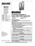
Owners
Manual
FOR POTABLE WATER
HEATING ONLY
NOT SUITABLE FOR
SPACEHEATING
NOT FOR USE IN
MOBILE HONES
Model No.
153.336151
153.336251
153.336312
153.336351
153.336412
153.336451
153.336512
153.336551
153.336751
153.336812
153.336851
153.336912
153.336951
30 Gal. Short
40 Gal. Short
30 Gal. High Altitude,
30 Gal.
40 Gal. High Altitude
40 Gal.
50 Gal. High Altitude
50 Gal.
30 Gal. Propane (LE)
40 Gal. Propane (LP.)
High Altitude
40 Gal. Propane (I_E)
50 Gal. Propane (LP.)
High Altitude
50 Gal. Propane (LP.)
POWER
MISER M6
GAS
WATER
HEATER
• Care and Maintenance
• Troubleshooting
• Parts List
• Safety Instructions
• Installation
• Operation
For Your Safety
AN ODORANT
IS ADDED
WATER HEATER
TO THE GAS USED BY THIS
WARNING:
If the information in these instructions are not fol- I
lowed exactly, a fire or explosion may result, causing property I
damage, personal injury or death•
I
-Do not store or use gasoline or other flammable vapors and liquids
,n the vicinity of th's or any other apprance.
-WHAT TO DO IF YOU SMELL GAS
• Do not try to light any appliance.
• Do not touch any electr,'cal switch; do not use any phone in your
building•
.
.
Immediately
call your gas supplier from a neighbors phone.
Follow the gas supplier'sinstructions.
If you can not reach your gas suppl,er, call the fire department.
-Instal.lation and service must be performed
serv,ce agency or the gas suppl,er.
Caution:
Read and Follow
All Safety Rules and
Operating Instructions
Before First Use of
This Product.
Improper installation, adjustment, alteration,
service or maintenance can
cause DEATH, SERIOUS BODILY INJURY, OR PROPERTY DAMAGE. Refer to
I this manual for assistance or consult
atWARNING
the local Sears Service Center or gas utilit), for further information.
Flammable vapors may be drawn
by air currents from other areas of the 1
AWARNING
structure to this appliance.
I
Savethis Manual for Future Reference.
by a qualified installer,
AWARNING
]
READ THE GENERAL SAFETY SECTION BEGINNING ON INSIDE COVERB
AND THEN THIS ENTIRE MANUAL BEFORE INSTALLING OR OPERATING THIS WATER HEATER.
Sears, Roebuck and Co., Hoffman
Estates, IL 60179 U.S.A.
Safety Precautions
AWARNING
I
Improper installation, adjustment, alteration, service or I
maintenance can cause DEATH, SERIOUS BODILY I
INJURY, OR PROPERTY DAMAGE. Refer to this manual for assistance or consult your local Sears Service
Center for further nformat on.
AWARNING
WATER HEATERS EQUIPPED FOR ONE TYPE GAS
ONLY: This water heater is equipped for one type gas
only. Check the model rating plate near the gas control
valve for the correct gas. DO NOT USE THIS WATER
HEATER WITH ANY GAS OTHER THAN THE ONE
SHOWN ON THE MODEL RATING PLATE. Failure to
use the correct gas can cause problems which can result in
DEATH, SERIOUS BODILY INJURY, OR PROPERTY
DAMAGE. If you have any questions or doubts consult
your gas supplier or local utility.
_,WARNING
INSTALLATIONS IN AREAS WHERE FLAMMABLE LIQUIDS (VAPORS) ARE LIKELY TO BE PRESENT OR
STORED (GARAGES, STORAGE, AND UTILITY AREAS,
ETC): Flammable liquids (such as gasoline, solvents,
propane (LP) or butane, etc.), all of which emit flammable
vapors, may be improperly stored or used in such areas.
The gas water heater pilot light or main burner can ignite
such vapors. The resulting flashback and fire can cause
death or serious burns to anyone in the area, as well as
property damage.
If installation in such areas is your only option, then the
installation must be accomplished in a way that the pilot
flame and main burner flame are elevated from the floor
at least 18 inches. While this may reduce the chances of
flammable vapors from a floor spill being ignited, gasoline
and other flammable substancesshould never be stored or
used in the same room or area containing a gas water
heater or other open flame or spark producing appliance.
NOTE: Flammable vapors may be drawn by air currents
from other areas of the structure to the appliance.
AWARNING
If this water heater will be used in beauty shops, barber
shops, cleaning establishments, or serf-service laundries
with dry cleaning equipment, it is imperative that the
water heater or water heaters be installed so that combustion and ventilation air be taken from outside these
areas. Refer to the "Locating The New Water Heater"
section of this manual and also the latest edition of the
National Fuel Gas Code, ANSI Z223.1, also referred to as
NFPA 54 for specificsprovided concerning air required.
AWARNING
A fire can start if combustiblematerialssuchas clothing
cleaningmaterials,or flammableliquidsare placedagainst
or nextto thewater heater.
&WARNING
At the time of manufacture this water heater was provided with a combination temperature-pressures relief
valve certified by a nationally recognized testing laboratory that maintains periodic inspection of production of
listed equipment or materials, as meeting the requirements for Relief Valves and Automatic Gas Shutoff
Devices for Hot Water Supply Systems, and the latest
edition of ANSI Z21.22 and the code requirements
of
ASME. If replaced, the valve must meet the requirements of local codes, but not less than a combination
temperature and pressure relief valve certified as meeting the requirements for Relief Valves and Automatic
Gas Shutoff Devices for Hot Water Supply Systems,
ANSI Z21.22 by a nationally recognized testing laboratory that maintains periodic inspection of production of
listed equipment or materials.
The valve must be marked with a maximum set pressure
not to exceed the marked hydrostatic working pressure
of the water heater (150 Ibs.lsq. in.) and a discharge
capacity not less than the water heater input rate as
shown on the model rating plate. (Electric heaters watts divided by 1000 x 3415 equal BTUIHr. rate.)
Your local jurisdictional authority, while mandating the
use of a tempereture-pressure
relief valve complying
with ANSI Z21.22 and ASME, may require a valve model
different from the one furnished with the water heater.
Compliance with such local requirements must be satisfied by the installer or end user of the water heater with
a locally prescribed temperature-pressure
relief valve
installed in the designated opening in the water heater in
place of the factory furnished valve.
For safe operation of the water heater, the relief valve
must not be removed from it's designated opening or
plugged.
The temperature-pressure relief valve must be installed
directly into the fitting of the water heater designated for
the relief valve. Position the valve downward and provide
tubing so that any discharge will exit only within 6 inches
above, or at any distance below the structural floor. Be
certain that no contact is made with any live electrical
part. The discharge opening must not be blocked or
reduced in size under any circumstances. Excessive
length, over 30 feet, or use of more than four elbows carl
cause restriction and reduce the discharge capacity of
the valve.
No valve or other obstruction is to be placed between
the relief valve and the tank. Do not connect tubing
directly to discharge drain unless a 6" air gap is provided.
To prevent bodily injury, hazard to life, or property damage, the relief valve must be allowed to discharge water
in quantities should circumstances demand, if the discharge pipe is not connected to a drain or other suitable
means, the water flow may cause property damage.
The Discharge Pipe:
Must not be smaller in size than the outlet pipe size of
the valve, or have any reducing couplings or other
restrictions.
Must not be plugged or blocked.
Must be of material listed for hot water distribution.
Must be installed so as to allow complete drainage of
both the temperature-pressure
relief valve, and the
discharge pipe.
Must terminate at an adequate drain.
Must not have any valve between the relief valve and
tank.
Safety Precautions
A, WARNING
&WARNING
A gas water heater cannot operate properlywithout the
correct amount of air for combustion. Do not install in a
confined area such a closet, unless you provide air as
shown in the "Locating The New Water Heater" section.
Never obstruct the flow of ventilation air. If you have any
doubts or questions at all, call your gas company. Failure
to provide the proper amount of combustion air can result
in a fire or explosion and can cause DEATH, SERIOUS
BODILY INJURY, OR PROPERTY DAMAGE.
This water heater must not be installeddirectly on carpeting. Carpeting must be protected by a metal or wood
panel beneath the applianceextending beyondthe full
width and depth of the appliance by at least 3 inches
(76.2mm) in any direction,or if the appliance is installed
in an alcoveor closet,the entire floor must be coveredby
the panel. Failure to heed this warning may result in a
fire hazard.
AWARNING
AWARNING
VENT DAMPERS - Any vent damper, whether it is operated thermally or otherwise must be removed if its use
inhibits proper drafting of the water heater.
Thermally Operated Vent Dampers: Gas-fired water
heaters having thermal efficiency in excess of 80% may
treduce a relatively low flue gas temperature. Such temmratures may not be high enough to properly open thermally operated vent dampers, This would cause spillage of
flue gasesand may cause carbon monoxide poisoning.
Vent dampers must bear evidence of certification as complying with the latest edition of American National
Standard ANSI Z21.68 (ANSI Z21.66 & 67, respectively,
cover electrically
and mechanically actuated vent
dampers), Before installation of any vent damper, consult
mar local Sears Service Center or the gas utility for further information,
HOTTER WATER CAN SCALD: Water heaters are
intended to produce hot water. Water heated to a tomperature which will satisfy clothes washing, dish washing,
and other sanitizing needs can scald and permanently
Injure you upon contact. Some people are more likely to
be permanently injured by hot water than others. These
include the elderly, children, the infirm, or physically/men.
tally handicapped. If anyone using hot water in your home
fits into one of these groups or if there is a local code or
state law requiring a certain temperature water at the hot
water tap, then you must take special precautions. In addition to usingthe lowest possibletemperature setting that
satisfies your hot water needs, a means such as a mixing
valve, should be used at the hot water taps used by these
people or at the water heater. Mixing valves are available
at plumbing supply or hardware stores. Follow manufacturors instructions for installation of the valves. Before
changing the factory setting on the thermostat, read the
"Temperature Regulation" section in this manual.
AWARNING
• The appliance and its individual shutoff valve must be disconnected from the gas supply piping system during any
pressure testing of the gas system at test pressures in
excessof I/2 pound per square inch (3.SkPa).
• The appliance must be isolated from the gas supply piping system by closing its individual manual shutoff valve
during any pressure testing of the gas supply piping system at test pressures equal or less than I/2 pound per
square inch (3.SkPa).
AWARNING
Soot build-up indicates a problem that requires correction before further use. Turn "off" gas to water heater
and leave "off" until repairs are made, because failure to
correct the cause of the sooting can result in a fire or
explosion causing DEATH, SERIOUS BODILY INJURY,
OR PROPERTY DAMAGE.
AWARNING
_,WARNING
Chemical vapor corrosion of the flue and vent system
may occur if air for combustion contains certain chemical
vapors. Spray can propellants, cleaning solvents, refrigerator and air conditioner refrigerants, swimming pool
chemicals, calcium and sodium chloride, waxes, bleach,
and process chemicals are typical compounds which are
potentially corrosive.
BEFORE LIGHTING
[PROPANE (L.P.) GAS WATER
HEATERS]: Propane (L.R) gas is heavier than air. Should
there be a leak in the system, the gas will settle near the
ground. Basements, crawl spaces, skirted areas under
mobile homes (even when ventilated), closets and areas
below ground level will serve as pockets for the accumulation of this gas. Before a_empting to light or relight the
water heater's pilot or turning on a nearby electrical light
switch, be absolutely sure there is no accumulated gas in
the area_ Search for odor of gas by sniffing at ground level
in the vicinity of the appliance, It"odor is detected, follow
steps indicated at "For Your Safety" on the cover page of
this manual then leave the premises.
AWARNING
Obstructed or deteriorated vent systems may present a
serious health risk or asphyxation.
Safety Precautions continued on page 4
3
Safety Precautions
AWARNING
1
The water heater with draft hood Installed must be prop-/
eriy vented to a chimney which terminates outdoors.|
Never operate the water heater unless It is vented to the/
outdoors and has adequate air supply to avoid risks ofl
improper operation, explosion or asphyxiation.
|
AWARNING
Minimum clearances between the water heater and combasttble construction are I" at the sidesand rear, 4" at the
front, and 6,_'filxln the vent I_e. CJearancefrom the top of the
jacket is 18 on most medels. Note thet a lesser dimansion m_
be allowedon some models. Refer to the label on the vra_
heeter adjacentto the gascantrolvalvefor ail deanmce_
AWARNING
[
Do not use this appliance if any part of it has been under I
water. Immediately call a Sears Service Technician to [
inspect the appliance and to replace the gas control or any
part of the burner system which kes been under water.
_WARNING
HYDROGEN GAS: Hydrogen gas can be produced In a hot
water system that has not been used for a long period of
time (generally two weeks or more). Hydrogen gas is
extremely flammable and explosive. To prevent the posslbility of Injury under these conditions, we recommend the
hot water faucet be opened for several minutes at the
kitchen sink before any electrical appliances which are
connected to the hot water system are used (suchas a dishwasber or washing machine). If hydrogen gas is present,
there will probably be an unusual sound similar to air
escaping through the pipe as the hot water faucet is
opened. There must be no smoking or open game near
the faucet at the time it is open.
AWARNING
INSULATING
JACKETS: When Installing an external
water heater Insulation jacket on a gas water heater:
DO NOT cover the temperutoro-pressure rellof veJve.
DO NOT put insulation over any part of the top of the
gas water heater.
DO NOT put insulation over the gas control valve or gas
control vaivelburner cover, or any access areas to the
burner.
DO NOT let insulation around the gas water heater to
get within 8 inches of the floor (air must get to the
burner).
DO NOT cover or remove operating instructions, and
safety related warning labels and materials affixed to the
water heater.
Failure to heed this will result in the possibility of a fire or
explosion.
ACAUTION
WATER HEATERS EVENTUALLY LEAKJ IostaJlation of
the water heater must be accomplished in such a manner
that If the tank or any connections should leak, the flow of
water will not cause damage to the structure. When such
locations cannot be uolded, a suitable drsJn pan should
be Installed under the water heater. Drain pans are avail.
able at your Iocai Sears store. Such a drain pan must be
not greater than I I/2 inches deep, have a minimum
length and width of at least 2 inches greater than the
water heater dimensions and must be piped to an adequate drain. The pan must not restrict combustion air
flow. Under no circumstances is the manufacturer
or
Sears to be held liable for any water damage in €onnection with this water heater.
Table of Contents
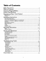
Safety Precautions ............................................................................................................
2-4
Table of Contents ............................................................................................................
5
Customer Responsibilities .............................................................................................
6
Product Specifications ....................................................................................................
6
Materials and Basic Tools Needed ...............................................................................
Materials Needed .....................................................................................................................................................................
Basic Tools ...............................................................................................................................................................................
Installation
Instructions
.......................................................................................................
s-16
Removing the Old Water Heater ...............................................................................................................................................
Facts to Consider About the Ix_tion .......................................................................................................................................
Combmtlon Ai.r and Ventilation for Appliances in Unconfined Spaces ...................................................................................
C_mbmtlon Air and Ventilation for Appliances in Confined Spaces .......................................................................................
Water Piping ...........................................................................................................................................................................
Teraperamre-Prc_ure Reliff Valve ...........................................................................................................................................
Filling the Water Heater ..........................................................................................................................................................
Venting ..............................................................................................................................................................................
Gas Piping .........................................................................................................................................................................
Imtallation Checklist ..............................................................................................................................................................
0
eratin
_"_ting
g
Instructions
.........................................................................................................................
.............................................................................................................................................................................
Temperatm_
Regulation ..........................................................................................................................................................
8
9
10
10
11
12
13
13-14
14-15
16
17-19
17-18
19
Service and Adjustment .................................................................................................
20-21
Tank (Sediment) Cleaning ......................................................................................................................................................
Venting System Inspection ......................................................................................................................................................
20
20
Burner Inspection ...................................................................................................................................................................
20
Burner Cleaning .....................................................................................................................................................................
L.E Gas Control Valve & Burner Assembly ............................................................................................................................
Draining .................................................................................................................................................................................
Temperature-Pressure Relief Valve Operation ..........................................................................................................................
Drain Valve Washer Replacement ...........................................................................................................................................
Housekeeping .........................................................................................................................................................................
Service ....................................................................................................................................................................................
20
20
21
21
21
21
21
Troubleshootin
g
Guide
........................................................................................................................
22-25
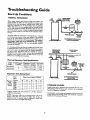
Start Up Condltiom ..........................................................................................................................................................
Thermal Expansion ..............................................................................................................................................................
Strange Sounds .....................................................................................................................................................................
Condensation .......................................................................................................................................................................
Smoke/Odor .........................................................................................................................................................................
22-23
22
22
23
23
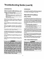
Operational Conditions .....................................................................................................................................................
Smelly Water ........................................................................................................................................................................
Air m Hot Warer Faucets ...................................................................................................................................................
23-24
23
23
High Temperature Shut Off System ......................................................................................................................................
Not Enough Hot Water ........................................................................................................................................................
Water is too Hot ...................................................................................................................................................................
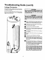
Leakage Checkpoints
..............................................................................................................................................................
24
24
24
25
PartsOrder List........................................................................................................
2s-31
5
Customer
Responsibilities
Thank You for
purchasinga
Sears water heater.
Properly installed and maintained, it should give you years of
trouble free service. If you should decide teat you want the new
water heater professionally installed by Sears call the local Sears
Service Center or any Sears store. They will arrange for prompt,
quality installation by Sears authorized contractors.
Ahhreviatiom Fomad In This IJastrttctlou Man.a1
I.A.S. - International Approval Services, A Division of CSA
A.N.S.I. - American National Standards Institute
• This manual contains instructions fur the installation, operation, and maintenance of the gas-fired water heater. It also
contains warnings through out the manual that you must read
and be aware of. All warnings and all instructions ire essential
to the proper operation of the water heater and your safety.
Since we cannot put everything on the first f_w pages, READ
THE ENTIRE MANUAL BEFORE ATTEMPTING
TO
INSTALL OR OPERATE THE WATER HEATER.
• The installation must conform with the instructions in this
• manual; gas company rules; and Local Codes, or in the
absence of Local Codes, with the latest edition of the National
Fuel Gas code, ANSI Z223.1, also referred to as NFPA 54.
This publication is available from your local government or
public library or gas company
or by writing NFPA,
Batrerymarch Park, Quincy, MA 02269.
• If after reading this manual you have any questions or do not
understand any portion of the instructions, call the Sears
Service Center.
• Carefully plan the place where you are going to put the water
heater. Correct combustion, vent action, and vent pipe installation are very imporiam in pte-aeming death from possible
carbon monoxide poisoning and fires.
Examine the location to ensure the water heater complies with
the OFacts to Consider About the Location" section in this
AWARNING
This gas-fired water heater is design certified by the
International Approval Services, A Division of CSA under
American National Standard/CSA Standard for Gas Water
Heaters AN$ Z21.10.1 ° CSA 4.1 (latest edition). The
installation must conform with this manual, Local Codes
and with the latest edition of the National Fuel Gas Code,
ANSI Z223.1:
This publicatmn is avallalde from your local government or
public library,
gas company, or by writing NFPA,
Batterymarch Park, Quincy, MA 02269.
nlRnual.
•
Read the _Safety Precautions" section, pages 2 through 4 of
this manual first and then the entire manual carefully. If you
don't follow the safety rules, the water heater will not operate
_Nroperly. It could cause DEATH,
SERIOUS
BODILY
.JURY AND/OR PROPERTY DAMAGE.
• For California installation this water heater must be braced,
anchored, or strapped to avoid falling or moving during an
earthquake. See instructions for correct installation procedures. Instructions may be obtained from ),our local dealer,
wholesaler, public utilities or California Office of the State
Architect, 400 P Street, Sacramento, CA 95814.
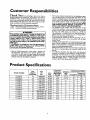
Product Specifications
MODEL NUMBER
153.336151
153.336251
153.336312
153.336351
153.336412
153.336451
153.336512
153.336551
153.336751
153.336812
153.336851
153.336912
153.336951
TANK
CAPACITY
IN GALLONS
TYPE
OF
GAS
30
40
30
30
40
40
50
50
30
40
40
NATURAL
NATURAL
NATURAL
NATURAL
NATURAL
NATURAL
50
50
NATURAL
NATURAL
PROPANE (L.EI
PROPANE (L.EI
PROPANE (L.E'
PROPANE (LP.)
PROPANE (L.E)
B._U.
RATE
30,000
35,000
33,500
33,500
35,500
35,500
35,500
35,500
33_500
35,500
35,500
36,000
36,000
RECOVERy
RATEGALLS.
PER HOUR @
90°F RISE
30.7
35.8
34.3
34.3
36.3
36.3
36.3
36.3
34.3
36.3
36.3
36,8
36.8
MINIMUM
VENT
PIPE
3" or 4"
3" or 4"
3"
3"
3"
3"
3"
3"
3"
3"
3"
3"
3"
DIMENSIONS IN INCHES
HEIGHTTO
DIAMETER [ACKETTOP
18
47
20
47½
16
56
16
56
18
56½
18
56½
20
56½
20
56½
16
56
18
18
20
20
56½
56½
56½
56½
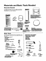
Materials
Materials
and Basic Tools Needed
Needed
To simplify the installation Sears has available the installation
parts shown below. You may or may not need all of tbese materials, depending on your type of installation.
WATER HEATER STAND 24"x24"x I E"
FOR USE WITH
WATER HEATERS
INSTALLED
IN RESIDENTIAL
GARAGES
HAVING
A DIAMETER
24"
OR LESS AND A RATED CAPACITY
7S
GALLONS
OR LESS
EXPANSION
TANKS
FOR THERMAL
EXPANSION
CONDITIONS AVAILABLE
IN
2 GALLON
AND $
FLEXIBLE
WATER
HEATER GAS CONNECTOR
WITH
FITTINGS
THROUGH
LOCAL
SEARS STORE OR
SERVICE CENTERS
WATER
HEATER INSTALLATION
KIT WITH
FLEXIBLE CONNECTORS
FOR
3/4" OR 112" THREADED
OR COPPER PLUMBING
GALLON
VENT
CAPACITY
PIPE
WATER
HEATER HEAT
TRAPS HELP REDUCE
HEAT
LOSS DUE TO THERMAL
SYPHONING
DRAIN PANS
AVAILABLE
IN 20" DIAMETER
FOR
WATER
HEATERS HAVING
A DIAMETER 18" OR LESS AND AVAILABLE
IN
28" DIAMETER
FOR WATER
HEATERS
HAVING
A DIAMETER
26" OR LESS
Basic Tools
You may or may not need all of these tools, depending on your
type of installation. These tools can be purchased at your local
Sears store,
•
•
•
•
•
•
•
Pipe Wrenches (2) 14"
Screwdriver
Tin Snips
6 Foot Tape of Folding Rule
Garden Hose
Drill
Pipe dope or Teflon Tape
ADDITIONAL
TOOLS NEEDED
WHEN SWEAT SOLDERING
• Tubing Cutters or Hacksaw
• Propane Torch
• Soft Solder
• Solder Flux
• Emery Cloth
• Wire Brushes
\
HACKSAW
GARDEN
HOSE
6 FOOT
TAPE
PIPE
WRENCH
SLOT-HEAD
PHILLIPS
SCREWDRIVER
314" WIRE
C>-.1
I/2" WIRE
BRUSH
BRUSH
SCREWDRIVER
TIN
PROPANE
TORCH
SNIPS
ROLL OF LEAD FREE
SOFT SOLDER
ROLL OF TEFLON
TAPE
(USE ONLY ON WATER
CONNECTIONS)
PIPE DOPE (SQUEEZE
TUBE)
USE FOR WATER AND
_AS CONNECTIONS)
ROLL OF EMERY
CLOTH
SOLDER
FLUX
TUBING
CUTTER
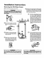
Installation
Removing
Q
Instructions
the Old Water
Heater
Turn _OFF _ the gas supply to the water heater.
I
*WARNING
Disconnect the vent pipe from the draft hood where
they connect to the water heater. In most installations
the vent pipe can be lifted off after any screw or other
attached devices are removed. Dispose of the draft
hood. The new water heater has the draft hood which
must be used for proper operation.
I
If the main gas line shutoff serving all gas appliances is I
used, al.so shut "OFF" the gas at each appliance. Leave all I
gas appliances shut "OFF" until the water heater installation is complete.
®
Turn UOFF" the water to the' water
heater. Some installations require that
the water be turned off to the entire
a. If you have co PPer PPi in g to the water
heater, the two copper water pipes can
be cut with a hacksaw approximately
four inches away from where they connect to the water heater. This will avoid
cutting
off the pipes too short.
Additional cuts can be made later if necessary. Disconnect the temperature-pressure relief valve drain line. When the
water heater is drained, disconnect the
hose from the drain valve. Close the
drain valve. The water heater is now
completely disconnected and ready to be
removed.
house,
QCheck
a_ain to make sure the gas supply
is OFF to the water heater. Then disconnect the gas supply connection from
the gas control valve_
Attach a hose to the water heater drain
valve and put the other end in a floor
drain or outdoors. Open the water heater
drain valve. Open a nearby hot water
faucet which will relieve pressure in the
water heater and speed draining.
AWARNING
I
The water passingout of the drain valve may be extremely I
hot. To avoid being scalded, make sure all connections are [
ttght and that the water flow is directed away from any
person,
b. If you have galvanized pipe to the water
heater, loosen the two galvanized pipes
with a pipe wrench at the union in each
line. A!so disconnect the piping remaining to the water heater. These pieces
should be saved since they may be needed when reconnecting the new water
heater. Disconnect the temperature-pressure relief valve drain line. When the
water heater is drained,disconnect the
hose from the drain valve. Close the
drain valve. The water heater is now
completely disconnectedand readyto be
removed.
A CAUTION
[
Mineral buildup or sediment may have accumulated in the I
old Water heater. This causesthe w_er heater to be much I
heavier than normal and this residue, if spilled out, could
cause staining.
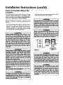
Installation
Instructions
(cont'd)
Facts to Consider About the
Location
You should carefully choose an indoor location for the new
water heater, because the placement is a very important consideration for the safety of the occupants in the building and for
the most economical use of the appliance. This water heater is
not for use in mobile homes or outdoor installation.
• The location selection must provide adequate dearances for servicing and proper operation of the water heater.
Whether replacing an old water heater or putting the water
heater in a new location, the following critical points must be
observed.
This water heater must not be imtelled direcdyon carpe_ng.
Carpeting must be protected by a metal or wood panel
beneath the appliance extending beyond the full width and
depth of the appliance by at least 3 inches(76.2mm) in any
direction, or if the applianceis installedin an alcoveor closet,
the endre gonr must be coremd by the panel. Failureto heed
this warningmay msuit in a fire hazard.
AWARNING
• The location selected should be indoors as dose as practical to
the gas vent or chimney to which the water heater vent is
going to be connected, and as centralized with the water piping system as possible. The water heater, as all water heaters,
will eventually leak. Do not install without adequate drainage
provisions where water flow will cause damage.
AWARNING
Minimum clearances between the water heater and combustible construction are I" at the sidesand rear, 4" at the
front, and 6,_'from the vont Pipe.Claarancefrom the tep of tbe
jacket is 18 on most model_ Note that a lesserdimensionmay
be allowedon some modelL Refer to the label on the water
hez_" edjacont to the gascontrolvaJvefor ail dearance_
ACAUTION
WATER HEATERS EVENTUALLY LEAK: Installation of the
water heater must be accomplishedin such a manner that if
the tenk or ony connectionsshouldlank, the how of water will
not causedamagn to the strootur_ Wben soch lucadonscan.
not be avoided,a suitabledrain pan shouldbe installedunder
the water heater. Drain pans are availableat your localSears
store. Such a drain pan must be not greater than 1% inches
dee_ have a minimum length and width of at least 2 inches
IFeater than the water heater dimensionsand must be piped
to an edequato drain.The panmust not restrict €ombustionair
flow. Under no circumstancesis the manuh_urer or Sears to
be held liable for any water dam,_e in connection with this
v_or heater.
YENTIL&TION
T P_qEW
AWARNING
AIR DUCT
Figure I ]
INSTALLATIONS IN AREAS WHERE FLAMMABLE UQUIDS
_GAPORS)
LIKELY TO
PRESENTAREAS,
OR STORED
ARAGES,ARE
STORAGE,
ANDREUTILITY
ETC),
Flammable liquids(such as gasoBno,solvents,propane(LP) or
butane, etc.), all of which emit flammable vapors, may be
improperlystoredor ased in such_s.
The gas water heart
pilot light or main burner can ignitesuchvapor_ The resulting
flashbackand Em can causedea_ or seriousburosto anyonein
the area, aswell asproportydamagn.
If installationin suchareasis youronly option,then the instelladon must be accomplishedin a way that the pilot flame and
main humor flame are elevated from tbe tk)or at least 18incheL
Wh_ this ma_ reducethe chancesof flammablevaporsfrom a
floorspillbeingignited,gasolineandother flammablesubstances
shouldneverbe storedor usedin the same room or area conraininga gaswater heater or other open flame or sparkproducingappliance.
NOTE: Flammable vaporsmay be drawn by air currents from
other amesof the structureto the appiiance.
AWARNING
A ps water bea_' cannotepera_ i_periy wltbeut the correct amonnt of elr for comlxe|tion. Do not instellin a confined
area soch a doset, unlessyou provideair es shownin the "Facts
to Comkler About the Location" section.Never obstruct the
flow of ventilationair. If youhwe any doubtsor quesdomat ail,
cellyanr gas€ompany.Faifureto Ix_vide the preper amount of
combustionair _m result in a tim or expiosionand can cause
DEATH, SERIOUS BODILY INJURn,OR PROPERTYDAMAGE.
AWARNING
If thiswator heater will be usedin beauty shops, berber shops,
cleaning establishments, or self-service laundries with dry
cleaningequipment, it is imperative that the water heater or
water heaters be installedso that combustion and ventilation
air be takan from ontslde these arees. Refer to the "Facts to
ConsiderAbout the Location" sectionof this manual and aiso
the latest edition of the National Fuel Gas Cede, ANSI Z223.1
also referred to as NFPA 54 fur specificsprovidedconcemin
air required.
AWARNING
Propellants of aerosolspraysand volatile compounds, (cleaners, chlorine based chemicals,refrigerants,etc.) in addition to
being highlyflammable in many cases,will alsochangeto €orrosivo hydrochloric acid when exposed to the combustion
products of the water heater. The resultscan be hazardo_
and also causeproduct failure.
9
Installation
Instructions
(cont'd)
Combustion Air and Ventilation
for Appliances Located in
Unconfined Spaces
Unconfined Space is a space whose volume is not less than 50
cubic feet per 1,000 Btu per hour of the aggregate input rating
of all appliances installed in that space. Rooms communicating
directly with the space in which the appliances are installed,
through openings not furnished with doors, are considered a
part of the unconfined space
In unconfined spaces in buildings, infiltration may be adequate
to provide air for combustion, ventilation and dilution of flue
gases. However, in buildings of tight construction (for example,
weather stripping, heavily insulated, caulked, vapor barrier, etc.),
additional air may need to be provided using the methods
described in Combustion Air and Ventilation for Appliances
Located in Confined Spaces, b.
1. When directly communicating with the outdoors,each opening shall have a minimum flee area of 1 square inch per 4,000
BTU per hour of total input rating of all equipment in the
enclosure. (See Figure3.)
2. When communicating with the outdoors through vertical
ducts, each opening shall have a minimum free area of 1
square inch per 4,000 BTU per hour of total input rating of
all equipment in the endosure. (See Figure4.)
Combustion Air and Ventilation
for Appliances Located in
Confined Spaces
Confined Space is a space whose volume is less than 50 cubic
feet per 1,000 Btu per hour of the aggregate input rating of all
appliances installed in that space.
at.ALL AIR FROM INSIDE BUILDINGS:
(See Page 8 Figure 1, and Figure 2 below)
The confined space shall be provided with two permanent
openings communicating directly with an additional room(s)
of sufficient volume so that the combined volume of all
spaces meets the criteria for an unconfined space. The total
input of all _, utilization equipment installed in the combined space shall be considered in making this determination.
Each opening shall have a minimum free area of one square
inch per 1,000 BTU per hour of the total input rating of all
gas utilization equipment in the confined space, but not less
than 100 square inches. One opening shall commence within
12 inches of the top and one commencing within 12 inches
of the bottom of the enclosure.
.I_LFT _R DUGT
' Ibo_ IIooq
Figure 4 ]
3. When communicating with the outdoors through horizontal
ducts, each opening shall have a minimum free area of 1
square inch per 2,000 BTU per hour of total input rating of
all equipment in the endosure. (See Figure 5.)
I Figure S ]
4. When ducts are used, they shall be of the same cross-sectional
area as the free area of the openings to which they connect.
The minimum short side dimension of rectangtdar air ducts
shall not be less than 3 inches. (See Figure 5.)
Figure 2 I
5. Louvers and Grilles: In calculating free area, consideration
shall be given to the blocking effect of louvers, grilles or
screens protecting openings. Screens used shall not be smaller
than ¼ inch mesh. If theffee area through a design of louver
or grille is known, it should be used in calculating the size
opening required to provide the free area specified. If the
design and free area is not known, it may be assumed that
wood louvers will be 20-25 percent free area and metal louvers
and grilles will have 60-75 percent free area. Louvers and
grilles shall be fixed in the open position or interlocked with
the equipment so that they are opened automatically during
equipment operation.
b. ALL AIR FROM OUTDOORS: (see Figures3-5)
The confined space shall be provided with twopermanent
openings, one commencing within 12 inches of the top and
one commencing within 12 inches from the bottom of the
enclosure. The openings shall communicate directly, or by
ducts, with the outdoors or spaces (crawl or attic) that freely
communicate with the outdoors.
6. Special Conditions Created by Mechanical Exhausting or
Fireplaces: Operation of exhaust fans, ventilation systems,
clothes dryers or fireplaces may create conditions requiring
special attention to avoid unsatisfactory operationof installed
gas utilization equipment.
Figure 3 ]
10
Installation
Water
Instructions
(cont'd)
Piping
AWARNING
•
HOTrER WATER CAN SCALD:Water heatotsam iotendedto
producehot water. Water heated to a tomperatom which will i
satisfyclotheswashing,dishweshing_and other suniti_
needs
am scaldend penmnen_ injure you upen contatt. Sorne peo4e are morn lilmlyto be permanently injuredby hot w_er _
other_ Theseincludethe elder_ children,the infim-,, or
ly/mentany handicapped,ffenyoneusinghot water in your home
Etsinto one ofthese greupsor if there isa local€odeor stato law
requiringa certaintemperature water at the hot water _ then
_u musttake specialprecautiom.In additionto usingthe lowest
_ssible temperature settingthat satisfiesyour hot water needs,
_mennssuchas a mixlng valve,thould be usudat the hot water
taps usedbythese people or at the wator heater.Mixingvalves
are availableat plumbingsupplyor hardwarestore_ Followmanufacturers instructions for installation of the valves. Before
changing the factory setting on the thermostat, read the
'q'empenttureRegulation"section in this manual
This water heater shall not be connected to any heating systems
or component(s)
used with a non-potable
water heating
appliance.
If a water heater is installed in a closed water supply system;
such as one having a back-flow preventer, check valve, water
meter with a check valve, etc.., in the cold water supply; means
shall be provided to control thermal expansion. Contact the
local utility or local Sears Service Center on how to control this
situation.
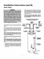
Look at the top cover of the water heater. The cold water
inlet is markedcold.
Put two or three turns of teflon tape
around the threaded end of _e threaded-to-sweat coupling
and atuund both ends of the ¾ threaded nipple. Using flexible connectors, connect the cold water pipe to the coldwater
inlet of the water heater.
NOTE: This water heater is super insulated to minimize
heat 1o. from the tank. Further reduction in heat loss
can be accomplished by insulating the hot water lines
from the water heater.
INSTALLATION COMPLETED USING
SEARS INSTALLATION KIT
-?
SHUTOFF
FLEXIBLE
WATER
CONNECTORS
VALVE
HOT OUTLET
TO HOUSE
THREADED
TO
SWEAT
COUPLING
THREADED
TO
SWEAT COUPLING
314" THREADED
COUPLING
314" THREADED
COUPLING
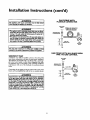
NOTE: To protect against untimely corrosion of hot and
cold water fittings, it is strongly recommended that di..electric unions or couplings be installed on this water heater
when connected to copper pipe.
WATER
LINE
COLD INLET
l
HOT
The illustration shows the attachment of the water piping to the
water heater. The water heater is equipped with ¾1,water connec_ions,
PRESSURE
RELIEFVALVE
NOTE: ff using copper tubing, solder tubing to an adapter
before attaching the adaptor to the cold water inlet connection. Do not solder the cold water supply line directly to the
cold water inlet. It will harm the dip tube and damage the
tank.
•
Look at the top cover of the water heater. The water oudet is
marked hot. Put two or three turns of teflon tape around the
threaded end of the threaded-to-sweat coupling and around
both. ends of the 3A threaded nipple. Using flexible connectors, connect the hot water pipe to the hot water oudet on
the water heater.
DISCHARGE
PIPE (Do not cap
or plug)
[]
FLOOR
11
DRAIN
Installation
Instructions
Temperature-Pressure
(cont'd)
Relief Valve
&WARNING
AWARNING
At the time of manufacture this water heater was provided
with a combination temperature-pressures relief valve certified by a nationally recognized testing laboratory that maintains periodic inspectionof productionof listed equipment or
materials, as meeting the requirements for Relief Valvesand
Automatic Gas Shutoff Devices for Hot Water Supply
Systems, and the latest edition of ANSI Z21.22 and the code
requirements of ASME. If replaced, the valve must meet the
requirements of local codes,but not lessthan a combination
temperature and pressure relief valve certified as meeting
the requirements
for Relief Valves and Automatic Gas
Shutoff Devicesfor Hot Water SupplySystems, ANSI Z21.22
by a nationally recognized testing laboratory that maintains
periodic inspection of production of listed equipment or
materials.
The valve must be marked with a maximum set pressurenot
to exceed the marked hydrostatic working pressure of _le
water heater (150 Ibs./sq. in.) and a discharge capacity not
lessthan the water heater input rate as shownon the model
rating plate. (Electric heaters, watts divided by 1000 x 3415
equal BTU/Hr. rate.)
Your localjurisdictionalauthority, while mandatingthe use of
a temperature-pressure relief valve complying with ANSI
Z21.22 and ASHE, may require a valve model different from
the one furnishedwith the water heater.
Compliance with such local requirements must be satisfied
by the installer or end user of the water heater with a locally
prescribed temperature.pressure relief valve installed in the
designatedopening in the water heater in place oftbe factory furnishedvalve.
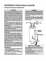
For safe operation of the water heater, the relief valve must
not be removed from it's designatedopening or plugged.
The temperature.pressure relief valve must be installed
directly into the fitting of the water heater designatedfor the
relief valve. Position the valve downward and provide tubing
so that any dischargewill exit only within 6 inchesabove, or
at any distance below the structural floor. Be certain that no
contact is made with any live electrical part. The discharge
opening must not be blocked or reduced in size under any
circumstances.Excessivelength, over 30 feet, or use of more
than four elbows can cause restriction and reduce the dischargecapacity of the valve.
No valve or other obstruction is to be placed between the
relief valve and the tank. Do not connect tubing directly to
discharge drain unlessa 6" air gap is provided. To prevent
bodily injury, hazard to life, or property damage, the relief
valve must be allowed to dischargewater in quantities should
circumstancesdemand. If the discharge pipe is not connected to a drain or other suitable means, the water flow may
causeproperty damage.
The DischargePipe:
Must not be smaller in size than the outlet pipe size oftbe
valve, or haveany reducing couplingsor other restrictions.
Must not be pluggedor blocked.
Must be of material listed for hot water distribution.
Must be installed so as to allow complete drainage of beth
the temperature-pressure relief valve, and the discharge :
pipe.
Must terminate at an adequate drain.
Must not haveany valve between the relief valve and tank.
The temperature-preesure
relief valve must be manually
operated at least once a year. Caution shoukl be taken to
emure that (I) no one ls in front of ov around the outlet of
the temperature-pressure rer_f valve dischargeline, and (2)
the water manually discharged will not cause any bodily
injury or property damage because the water may be
extremalyhot
ff after manually operating the valve, it fails to completely
reset and continnesto release water, immediately dose the
cold water inlet to the water heater, follow the draining
instructions, and replace the temperature-pressuro relief
valvewith a new one.
HOT
SHUTOFF
VALVE
COLD
PRESSURE
RELIEF VALVE
"DISCHARGE
PIPE
(Do not cap or plug)
[]
6" AIR GAP
FLOOR
DRAIN
RELIEF VALVEOPENING
At the time of manufacture,thiswater heater was prodded _
a combinationtemperature-pressure
rein _e listed u comp_[ngwiththe standardfor relief valvesand
automaticgas thut_ff devicesfor hot water supplysystems,ANSI Z21.22. fie< _fe
operationof the water heater,the relief valvemust not be remo_l from its designated
pointof insta_l_onor plugged.
Yourlocal jurisdictional
authori_, while mandatingthe use of a temperature-pressure
rel_ vahe complyingwith ANSI Z21.22 andASME,may requirea va_ mo_el differont
from the o_e furnishedwith _e water heater
Compliancewith suchlocalrequirements must be satisfiedby the installeror end user
of the water heater with a locallyprescdfiedtemperature-pressurerelief valve_ns_led
in the designated
openingin the water fieate_
See manualheading-_TemperatuR-Fressure
ReliefValves"for installationand maintenance of relief val_, dischargeline,andother safetypreca_ons.
]2
Installation
Filling the Water
Instructions
(cont'd)
Heater
A, CAUTION
Neveruset_s water heaterunlessIt is completelyfilledwith
water.Topreventdamageto the tenk, thetenk mustbefilled
with water. Water must flow from the hot water faucet
before',',,min
E "ON" gasto thewaterheater.
For proper ventingin certain installations,a largerdiametervent
pipe may be necessary.Due to great variancesin installations,
unforeseeableby the manufacturer of the waterheater, you must
consult your gas company to aid you in determiningthe proper
ventingfor your water heater from the vent tables in the latest
edition of the National Fuel Gas Code ANSI Z223.1, also
referredto as NFPA 54.
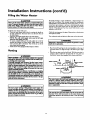
To fill the water heater with water:
• Close the water heater drain valve by turning the handle to
the right (dockwise). The drain valve is on the lower front of
the water heater.
• Open the cold water supply valve to the water heater.
NOTE: The cold water supply valve must be left open
whco th© water heater is in use.
• To insure complete filling of the tank, allow air to exit by
opening the nearest hot water faucet. Allow water to run
until a constant flow is obtained. This will let air out of the
water heater and the piping.
• Check all newwater piping for leaks. Repair as needed.
Check the ventingsystem for signsof obstruction or deterioration
and replace if needed.
The combustion and ventilationair flow must not be obstructed.
AWARNING
J
vent systerm may presenta serioos 1
Oe_uctod or _
health riskor asphy]d_on.
I
• Place the draft hood legs in the receiving holes on the top of
the water heater. The legs will snap in the holes to give a tight
fit.
• Place the vent pipe over the draft hood. With the vent pipe in
position, drill a small hole through both the vent pipe and
draft hood. Secure them together with a sheet metal screw.
Venting
AWARNING
VENT DAMPERS. Any vent damper, whether it is opel-dted
thermany or otherwisemust be removedIf Itsuseinhibitsprop
er draffingof the water heater.
Thermally Operated Vent Dampem Gas-fired water heaters
havingthemml e4r_ency In e_cessof 80% nmyproduce a rela-
DRAFT
HOOD
,_a_t_.
t_velylowIluegmtemperature.Suchtemperatures
n_/not be
IVENT_I J _
_r
_
f
_LF_'j_,
T HOOD
VENT TO OUTDOORS
CHIMNEY
high enough to properly open thermally operated vent
damperLThiswooldcausespillage
of Iluegasesandnw cause
c._onrnono_de
po_o_
.V_ dampmmu_bmreadeace
ofcenmcaeo,
ascomping
OR
DRAFT
with the latest editJonof American National Standard ANSI
Z21.68 (ANSI 2:21.66 & 67, respectively,coverelectricallyand
mechanicallyactuated vent darnpersgBeforeImtalla_n of any
vent _
€onsultyour localSearsServiceCenter or the ips
AWARNING
u_y forfurtherhafonnatk_
TH_v,.._ he_ wlth
d__
I
re.st_ Fo_,'lyI
vented to a chimneywhich terminates outdoors. Never oper- I
ate the wator heater unlessit isvented to the outdoorsand hasI
adequato air supplyto avoid rislmof improper op_q'aflon,explo-I
AWARNING
To insureproperve_
of this gas-firedwater heater,the
correctventpipediame_r mustbe utilized.Anyadd'talons
or
deledom of other gas appliances on a €ommon vent wi_ this
water heater may ad,na'sely affect the _
of the water
hea_. Coosultthe IoealSearsServiceCentoror gasutilityif
anysuchchanges
are planned.
AWARNING
I
The vent pipe ftom the wator heater must be no lessthan the I
diameter of the draft hood outlet on the water heater, and
I _x_
13
slope upward to the chimney at least ¼ inch per linear I
Installation
Venting
Instructions
(cont'd)
(cont'd)
Gas Piping
All vent gases must be completely vented to the outdoors of the
structure (dwelling). Installonly the draft hood provided with
the new water heater and no other draft hood.
Vent pipes must be secured at each joint with sheet metal screws.
AWARNING
Make sure the gas supplied is the same type listed on the
model ra_ng plate. The inlet gas pressure must not exceed
Ifl.S in. water column (2,6k_) for natural gasor 13 i_ water
column (3.2kPa) for propane (LR) ge_ The minimum inlet
gas prossum listed on the model rating plate is for the purposeof input ad'FWanont.
CHIMNEY
TO
RISE
?:O .EAR
RISE PER LINEAR
AWARNING
If the ges conerolvalve is subjecU_ to pressuresexceeding 'A
pound per square inch (3.Side), the damage tO the gascon.
!
VENT PIPE INSTALLATION
trnl vaJvecould reanlt in a fire or explosionfrom lealdngga_
There must be a minimum of 6" dearance between single wall
vent pipe and any combustible materi_l. Fill and seal any clearance between single wall vent pipe and combustible material
with mortar mix, cement, or other noncombustible substance.
For other than single wall, follow vent pipe manufacturer's dearance specifications. To insure a tight fit of the vent pipe in a
brick chimney, seal around the vent pipe with mortar mix
A W'_RNING
1
If the main gas line shutoff servingaJl gasappliancesk used,|
alsoturn "OFF" the gasat each appliance.Leaveall gasappli- |
antes shut of/until the water heater installationiscomplete. ]
cement.
A gas llne of sufficient size must be run to the water heater.
Consult the latest edition of National Fuel Gas Code ANSI
Z223.1, also referred to as NFPA54 and the gas company concerning pipe size.
AWARNING
Failureto haverequireddexrdncesbetweenvent pipingand
combustible
materialwillresultina firehazard.
There must be:
• A readily accessible manual shut offvalve in the gas supply line
serving the water heater, and
• A drip leg (sediment trap) ahead of the gas control valve to help
prevent dirt and foreign materials from entering the gas control
A WARNING
Be sureventpipeisproperlyconnectedto prevonte_capeof
dangerous
fluegaseswhichcouldcausedeadly_/x_tion.
valve.
• A flexible gas connector or a ground joint union between the
shutoffvalve and control valve to permit servicing of the unit.
Be sure to check all the gas piping for leaks before lighting the
water heater. Use a soapy water solution, not a match or open
flame. Rinseoff soapy solution andwipe dry.
AWARNING
Chemicalvaporcorrosionof the flue and vent systemmay
occurtf air for combustioncomainscert_ chemicalvapor_
Spraycanpropellants,cleaningsolvents,refrigeratorand air
conditionerrefrigerants,swimmingpool chemicals,calcium
andsodiumchloride,waxes,bleach,andprocess
chemicals
are
typicalcompounds
whicharepotenti_dly
corrosive.
Standard Models are for installation up to 3,300 feet above sea
level.
High Altitude Models are for installation from 3,300 to 5,500
_t abo_e sea level.
Ifa standard model is installed above 3,300 feet or a high altitude
model is installed above 5,500 feet, the input rating must be
reduced at the rate of 4 percent for each 1,000 feet above sea level.
Contact your local Sears Service Center or gas utility for further
information.
14
Installation
Instructions
(cont'd)
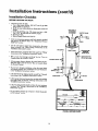
GAS PIPING WITH
FLEXIBLE
CONNECTOR
The appliance and its gas connection must
AWARNING
be leak tested
before placingthe appliancein operation.
GAS SUFFLY
PIPING
FLEXIBLE GAS CONNECTOR
&WARNING
LABELED AS COMPLYING
WITH ANSI STANDING
• The applianceand its individualshutoffvalve must be disconnected from the gassuppiypiping systemduring any pl_sure
testing of the gas system at test pressuresin excess of
poundper squareinch(3._kl_).
• The appliancemust be isolatedfrom the gassupplypipingsy_
tem by dosingits individualmanual shutoff valve during any
pressuretasl_ngof the gas supplypiping system at test pressures equalor lessthan _ peued per square inch(3.5Idea).
GROUNO
UNION(Optional)
T
3" min.
_Sedimer_ trap)
GAS
CONTROL
VALVE
AWARNING
1
CAP
Use pipe joint compound or teflon tape marked as being[
resistantto the action of pem_um [Propeue (L.R)] _
|
SEDIMENT
GAS PIPING WITH
ALL BLACK
PIPE TO GAS CONTROL
TRAP
A sediment trap shall be installed as close to the inlet of the
water heater as practical at the time of water heater installation.
The sediment trap shall be either a tee fitting with a capped nipple in the bottom outlet or other device recognized as an effective sediment trap. If a tee fitting is used, it shall be installed in
conformance with one of the methods of installation shown
below.
GAS SUPPLY
FtFING
GROUND JOINT
Connecting the gas piping to the gas control valve of the water
heater can be accomplished by either of the two methods shown.
UNION
h, WARNING
Contnminants in the gas linasrow/cause improper operation
of the gas control valve th_ may resolt in fire or explosion.
Before attaching the gas line be sure tl_t all gas pipe isdean
on the inside.To trap any dirt or foreign material in the gas
supply line, a drip leg (sometimes called a sediment trap)
must be incorporated in the piping. The drip leg must be
readily accessible.Install in accordancewith the "Gas Piping"
section. Refer to the latest edition of the National Fuel Gas
Code, ANSI 7.223.I, also _
to as NFPA 54.
15
(O{_Jonal)
T_
_
IRON
Installation
Instructions
Installation
Checklist
BEFORE
THE PILOT:
LIGHTING
(cont'd)
• Check the gaslines forleaks.
a. Use a soapy water solution• DO NOT test for gas leaks
usinga match or open flame.
b. Brush the soapy water solution on all gas pipes, joints and
fittings.
c. Check for bubbling soap• This means you have a leak.
Turn OFF gasandmake the necessaryrepairs.
d. Recheckfor leaks.
e. Rinseoffsoapy solution and wipe dry.
•
VENT
PIPE TO
OUTDOORS
OR CHIMNEY
SHUTOFF VALVE
COLD
Is the new temperature-pressure relief valve properly installed
and piped to an adequate drain? See "Temperature-Pressure
Relief Valve" sexxiott.
UNION
• Are the cold and hot water lines connected to the water
heater
correctly?
See
_Water
Piping" instructions in the
¢*
.
.
s_
.
Installation
Instrucuons
section.
GAS SUPPLY
DRAFT HOOD
PRESSURE
RELIEF VALVE
• Is the water heater completely filledwith water? See "Filling"
instructions in the "InstallationInstructions" section.
• Will a water leak damageanything? See the "Facts to
Consider Aboutthe Location section.
(Do not r.ap or plug)
SH
• Is there proper clearance between the water heater and anything that might catch fire. See the Factsto Consider About
the Location section.
• Do you have adequate ventilation so that the water heater
•
....
will
operateproperly._ See *cCombustion
Air and VentilaDon.
in the _Installation Instructions" section.
• Is the drafthood vent piping properly secured? See _Venting"
instructions in the "Installation Instructions" section.
DRAIN
6" AIR GAP
VALVE
• Is there proper dearancebetween the vent pipe and anything
that might catch on fire? See _Venting_ instructions in the
"Instalhtion Instructions" section.
FLOOR
DRAIN
• Is the vent pipe properlysloped and does the vent terminate
outdoors? See "Venting instructions in the Installation
Instructions" section.
•
Do you need to call your gas company to check the gas pipe
arid its hookup?" section,
MODEL
16
RATING
PLATE
Operating
Instructions
Lighting
AWARNING
BEFORE LIGHTING
[PROPANE (L.P,) GAS WATER I
HEATERS]: Propane (I.R) gasis heavier than air. Shouldthere
be a leak in the system, the gas will settle near the ground.
IBasements, crawl spaces,skirted areas under mobile homes
(emnwbenventilatod),
dosetsandareasla_owgroundle_ wili
serve as pockets for the accumulation of this gas. Before
attempdng to lightor religh¢the water beator_ pilot or turning
on a nearby electricallight switch,be absolutelywm them isno
aeaumulat_ ps h_tho are_ Seazchfor oclorof ps bymiring at
ip_und levelin the vicinityof the appliance. If odor is detected,
follow stepsindicatedat "For YourSafety" on the coverpageof
thismanuaJthen leavethe pmmise_
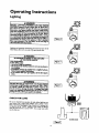
Figure 6 I
Lighting and operating instructions are located on front of the
water heater, above or to one side of the gas control valve.
AWARNING
AN ODORANT IS ADDED TO THE GAS USED
BY THIS WATER HEATER.
FOR YOUR SAFETY
IF YOU SMELL GAS:
Figure 7 ]
Oonottry to liShtanyap_nce.
Do not touch any elect_ol switch;do not me any phone In
yourbui_ng.
Immediatoly callyour gas supF4lerfrom a nelghho_ phone.
Followthe ips st_pt_'a_sImtruction_
If you cannot reach your ilas supplier, call tbe Ere departmer_
AWARNING
OO NOT force the gasoa_zol knob. Use o_ your hand to
push it down to light t_ pilot, or to tom it to '_DN", "OFF"
or "PILOT". Never use a tax_ such as a lever, wrench or plb
ers. Do not hit or dama_ the knob. A _
hoob may
r_=uit in an _
_KI seriousInjury. ff you hove problem
turning the knob, caJIthe gassupplier immed'mtoly.
CHECK
I Figure 81
FOR LEAKS
Be sure to check all your gas pipes for leaks before lighting your
water heater. Use a soapy water solution, not a match or open
flame. Check the factory gas fittings after pilot is lit and gas control knob is still in "PIEOT _ position,_ Then, check the tlttings
when the main burner is turned "ON . Use a soapy water solution for this, too.
17
Operating
Instructions
Lighting
label on the water
FOR YOUR
heater
SAFETY
(cont'd)
as it appears
READ
above the thermostat
BEFORE
LIGHTING
WARNING
If you do not follow these Instru_ions exactly, a fire or explosion
may result causing properly damage, personal injury or loss of life.
A. Thisappliancehasa pilotwhichmustbe lightedby
hand.Whenlightingthepilot,followtheseinstructions
exazc_,
.
B. BEFOI_E
LIGHTING
smellall aroundtheappliance
area
for gas. Re sure to smell nextto the floor because
somegasis heavierthenairandwillsettleonthefloor.
WHATTODOIFYOUSMELLGAS
• Donottrytolightanyappliance.
• Do not touchany electricswitch;do not use any
phoneinyourbuilding.
• Immediately
callyourgas supplierfroma neighbor's
phone.Followthegasauppller's
instructions.
LIGHTING
• If you cannot reachyourgassupplier,call the fire
department.
C. Useonlyyourhandto pushin or turnthegascontrol
knob.Neverusetools.If theknobwillnot pushin or
turnbyhand,don'ttryto repairit, celta qualifiedservice technician.
Forceor attempted
repairmayresult
ina fireor explosion.
D. Do not usethis applianco
if anyperthas beenunder
water.Immediately
call a qualifiedservicetechnician
toinspecttheappliance
and to replaceanypertof the
controlsystemandany gas controlwhichhasbeen
underwater.
INSTRUCTIONS
1.STOP!Readthe safetyinformation
aboveonthiskd3et.
2.Removeouterdoor.
3. Set the thermostatto lowestsettingbyturningthe
watertemperature
dialclockwise,
([ "_)toits lowest
temperature
setting(witharrowon dial)as shown.DO
NOT FORCE.
4. 'rumgascontrolknobelockwi"J
se _'_tl to "OFF"position. Knobcannotbe turnedfrom"PILOT"to "OFF"
unlessknobIs depressedslightly.DO NOT FORCE.
(Figureg,paga17)
5. Waitfive(5) minutesto clearout anygas. If youthen
smellgas,STOP!Follow"B" in thesafetyinformation
aboveon this label,If youdon'tsmellgas,go to the
nextstep.
6. Remove(or open)innerdoor locatedbelowthe gas
controlunit.
7. Findpilot-follow
metaltubefromgascontrol.Thepilot
islocatedinfrontoftheburner.
PILOT BURNER _
THERMOCOUPLE
8.Ifyou don'tsmeltgas,turnknobongascontrolcounter
cleckwlse
_,(_ =to=PILOT"position.
(Figure7,page17)
9. Pushin controlknoball the way and hold down.
Immediately
light thepilotwitha match.Contfnueto
hold controlknobin for aboutone (1) minuteafter
thepilotIs lit. Releaseknobandit willpopbackup.
Pilotshouldremainlit. If If goesout,repeatsteps3
through8.
• lt'imob doesnotpopupwhenreleased,stopand
immediatelycall yourservicetechnicianor gas
supplier.
• If the pilot will not stay lit after severaltries,
depressandturnthe gascontrolknobclookwlse
_
to"OFF"andcallyourservicetechnician
or gassupplier.
(Figure6, page17)
10. Replace(or close)Innerdoor.Replaceouterdourif
doordoesnot covergascontrolon/offknob or temperatureadjustment
knob.(Figure9, page17)
11. Atarmslengthaway,turn gascontrol knobcounter-i
dnekwlse_
to thefull "ON" position.
Wemlng
do not use gas control knob to regulate gas
flow. (Figure8, page17)
12. At armslengthaway,set thethermostatto desired
setting.Themark( • ) HOTIndicative
of approximate
120°FIs preferredstartingpoint.Somelocallaws
mayrequirea lowerstartingpoint.If hotterwaterIs
desired,seeinstruction
manual
and"wamlng"below.
13,Replace
theouterdoorifnotreplacedinstep10.
WARNING
HotterwaterIncreasesther sk of sead njury.Beforechangng temperaturesettng see notructlon menus.
TO TURN
OFF
GAS TO APPLIANCE
2."rumgascontrolknobclockwise_V _ to"OFF"position. Knobcannotbe turnedfrom "PILOT"to =OFF"
unlessknobisdepressed
slightly.DONOT FORCE.
3. Replace
outerdoor(ifremoved).
1. Set the thermostatto lowest settingbyturningthe
watertemperature
dialclockwise
(F-"_) to itslowest
temperature
ssttlng (witharrowon dial)as shown.DO
NOT FORCE.
]8
Operating
Temperature
Instructions
(cont'd)
Regulation
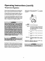
Due to the nature of the typical gaswater heater, the water tem_oeraturein certain situations may vary up to 30°F higher or
wer at the point of use such as, bathtubs, showers, sink, etc.
Turn the water temperature dial clockwise_.ff'_)
to decrease
the temperature, or counterclockwise (€ "_ _'_) to increase the
temperature.
This means that when the temperature adjustment dial is set at
the mark approximating 120° t_,the actual'water temperature at
any hot water tap could be as high as 150°For as low as 90°E
?my water heater's intended purpose is to heat water. Hot water
is needed for cleaning (bodies, dishes, clothing). Hot water will
present a scald hazard. Depending on the time element and the
people involved (normaladults, children, toddlers elderly,
nflrm, etc.) scalding mayoccur at different temperatures.
AWARNING
HOTTERWATERCANSCALD:Waterheatersare intended
to
producehotwater.Water heatedto a temperaturewhichwill
satisfy
clotheswashing,
dishwashing,
andothersanitizing
needs
canscaldand permanen_injureyouuponcontect.Sernepeop|eam morelikelyto bepen'mmently
injuredbyhot waterthan
ob_er_Theseindudethedderly,children,
thoinflnrn,
or physic_d_E_s
.rn_dly handicapped.
If_.ne usinghot waterin yourhome
intooneofthesegroups
or ift_m _ a Io_ codeor slatelaw
requiring
a certaintem_._rature
waterat thehot watertap,then
_u musttakespecial
precautionL
In additionto usingbhelowest
ms_le temperature..se_ng
thatsatisfies
yourhotwaterneeds,
a means inch es a meangvalve,shoukl Imused at dm hot watt.
tapsusedbythosepeopleor at the waterhoat_, Mixingvzives
areavailableat plumbing
supply
or hardwarestore_Fotlowman.
ufacturersinstructionsfor installationof the valves,Before
changingthe factory settingon the thermostat, read the
"TemperatureRegulation"
sectioninthismanual.
PILOT
LIGHTING - Set here before lighting pilot.
• HOT- Is a thermostat setting of approximately
120°F, which will supply hot water at the
most economical temperatures. The temperature adjustment knob can be turned lower
than _HOT" if desired.
A - Is a thermostat
130°E
setting of approximately
B - Is a thermostat
140°E
setting of approximately
C - Is a thermostat
150°E
setting of approximately
VERYHOT - Is a thermostat setting of 160°E It is recommended that the dial be set lower whenever
possible.
AWARNING
NeverallowsmallchiMrento usea hot w-atertap, or to draw
their ownbathwater.Neverleavea chilclor handicapped
per.
sonunatfamded
in a baURubor slmwe¢,
NOTE: Water temperature range of 120°--140°F
mended by most dishwasher manufacturers.
The thermostat of this water heater has been factory set at its
lowest position, to reduce the risk of scald injury. It is adjustable
and must be reset to the desired temperature setting. The mark
(A) HOT indicative of approximately 120°F is the preferred
startin_ point. Some states have a requirement for a lower setting. Iryou need hotter water, follow directions for temperature
adjustment, but beware of the warnings in this section.
recom-
AWARNING
Should overheating
turn
19
occur or the gas r_pply fail to shut off,
OFF" the manual gas contrul _-alve to _e appliance.
I
I
I
Service and Adjustment
Tank (Sediment)
Cleaning
Sediment build-up on the tank bottom may create varying
amounts of noise, and if left in the tank will cause premature
tank failure. In some water areas, you may not be able to drain
all sediment deposits by simply draining the tank. In these cases
Mug Erad(part no. 23600) can be used to help removethe sediment deposits. This may be ordered from the Sears Service
Center. For ozdering,refer to the "Parts Order List"section.
AWARNING
Soot build-up indicates a problem that requires correction I
belbrefur_.., use.Turn"OFF" gesto watorheatorand lenveI
I "OFF" until n_airs are made, becausefailure to correct the I
] cause of the sooting can result in a fire or explosioncausing]
[UOXT.,SmOOS
ao{ac Nu , ¢mPRopmrv
Venting System Inspection
Burner Cleaning
At least once a year a visual inspection should be made of the
venting system.You should look For:
• Obstructions which could cause improperventing. The combustionand ventilationair flow must not be obstructed.
Damageor deteriorationwhich could cause improper venting
i or leakageof combustion products.
Rusted flakesaround top of water heater.
In the event your burner
instructions:
Loosedeposits on or around the burner can be removedby carefully using the hose of a vacuum cleaner inserted through the
accessdoor of the water heater. If the burnerneeds to be removed
for additional denning, call the Sears Service Center to remove
and dean the burner and correct the problem that required the
burner to be denned.
typ_ compounds
which
areporouslyoorrodve.
L.R Gas Control Valve & Burner
Assembly Replacement
Information
[
a serious
healthHskor asplc/_atfon.
AWARNING
[
AWARNING
PROPANE (LR) GAS CONTROL VALVEAND BURNER
ASSEMBLYREPLACEMENTINFORMATION.
sure the vent piping is properly connected to prevent
_engerous
flue gass_
which coud
cause deadly I
For Propane (LP.) Gas Models Only'.
Your water heater is equipped with a Propane (LR) gas
control valve and a main burner assembly with/eft hand
threads for the following r_ings end their connections.
AWARNING
I
If afcor Impection of the vent aystom you foond sooting or I
detertmalio_
some_ing
Iswrong. Call the local ges u_llty to [
(I)
€orrecttheproblempnd deanor n_locethe#ue andvon_ngI
before resuming operation of the water heater.
Burner
I
The connection betWeen the manifold and the
gas control valve (.6, to B) are left hand threads.
(2) The connection between the main burner orifice and the manifold (C to D) are left hand
threads. For ordering these replacement parts,
please refer to the "Parts Order List" section of
this manual.
Inspection
AWARNING
Do ont usethis applience if any part of it has benn onder vauDer.
Immediately call a Sears Service Technician to inspect the
appliance and to replace the gas control or any part of the
burner lystom wh chhas beenunderwater.
}
I
At leastonce a year a visual inspection should be made of the
main burner andpilot burner. The drawing is for your reference.
You should check for sooting
impair proper combustion.
which is not normal
use the following
NOTF_ The knob cannot be turned from _PILOT" to UOFF"
unless knob is depressed slighdy. DO NOT FORCE.
Chemical vapor corrosion of the flue and vent system may
occur if air for combustioncontains certain chemical
Spray can propellants, cleaningsolvents,refrigerator and air
conditioner refrigerants, swimming pool chemicals, calcium
end sodium chloride,waxeg bleach,and processchemicalsare
_
needs cleaning,
If iuspe_ctionof the burner shows t_ denning is required,turn
the gas control knob clockwise((
x0 to the "OFF_ position,
depressingslighdy.
&WARNING
. AWARNING
or &_iotat_ ,rants,/stam_ ma,/_
j
A\
and will
20
Service
and Adjustment
(cont'd)
Draining
&WARNING
When th_ldng the temlasmmm-pmsm_ re4L,€valve opera.
don, make sum that (I) no one isin frontefor aroundthe
outlet of the teml_nture-pr_m
r_ief vahasdtstharp line,
and (2) thatthe vram.manuallydi-_'har_ w"l not cameany
proper¢/damageberausethe watermaybeextremaiyhot.
If after manuallyoperatingthe valve,It fails to €om#etety
resetandcontinuesto releasewater, immediatelydosethe
coldwator inlet to the water heater, followthe draining
instructions,and replace the temperature-pressurerelief
valvewitha newone.
The water heater should he drained if being shut down during
freezing temperatures. Also periodic draining and eleanmg of
sediment from the tank may be necessary.
•
Tttrn the gas control knob to the _OFF" position.
CLOSE the cold water inlet valve to the water heater.
OPEN a nearby hot water faucet and leave open to allow for
draining.
Connect a hose to the drain valve and terminate to an ade_Uparedrain.
EN the water heater drain valve to allow for tank
draining.
NOTE* If the water heater is going to be shut down and
drained for an extended period, the drain valve should be
left open with hose connected allowing water to terminate
Drain Valve Washer
Replacement
to anadequate
drab.
•
•
•
Close the drain valve.
Follow instructions
in the _Filling The Water Heater"
section.
Follow the lighting instructions in the _Lighting" section to
restart the water heater.
Temperature-Pressure
Valve Operation
The temperature-pressure
at least
once
NOT_ For replacemtah me a *_" x "/d' • *ti"thick washe*
availableat your nearesthardwarestore.Foro_._
_pla_
meat washers,
referto the "PartsOrder Li_ secuom
i
Relief
relief valve must be manually operated
•
a year.
•
TEMPERATURE-PRESSURE
RELIEF VALVE
DISCHARGE
Follow
_Draining"
instructions.
urn "OFF"
gas supply
to water heater.
Turning counter clockwise, remove the hex cap below the
screw handle.
Remove the washer and put the new one in place.
Screw the handle and cap assembly back into the drain valve
and retighten using a wrench. DO NOT OVER TIGHTEN.
Follow instrucuons
in the "Filling The Water Heater"
section.
Check for leaks.
Follow the lighting instructions in the "Lighting" stction to
restart the water heater.
PIPE
Housekeeping
Failure to install and maintain
a new properly listed temperature-pressure relief valve will release the manufacturer
from any
claim which might result from excessive temperature
or pressure,
Vacuum around base of water heater for dust, dirt, and Linton a
regular basis.
Combustible materials such as clothing, cleaning materials, or
flammable liquids, etc. must not be placed against or adjacent to
the water heater.
To insure sufqcient ventilation and combustion air supply, proper clearances from the water heater must be maintained at all
AWARNING
If the temperature.pressure relief valve on the appliance
weeps or dischargesperiodically,this may be due to thermal
expansion. Your water heater may have a check valve
installed in the water line or a water meter with a check
valve. Consult the Sears Service Center for further infurmaDo not plug the temperature-pressure _lief valve,
time,$.
Service
Before calling for repair service, read the Start Up Conditions
and Operational
Conditions found in the Troubleshooting
Guide of this manual.
If a condition persists or you are uncertain about the operation
of the water heater, let a qualified person check it out.
Contact SEARS Repair Services
(1-g00-469-4663).
21
at 1-800-4-MY-HOME
Troubleshooting
Guide
Start Up Conditions
THERMAL
EXPANSION
HOT
COLD
WATER HEATER
COlDW_,TIR
(3)
INLET Fn-rlNG
pRESSURE
REDUCING
Water supply systems may, because of high line pressure, frequent cut-off,s, the effects of water hammer and otbets, have
installed devices such as pressure reducing valves, check valves,
back flow preventers, etc. to control these types of problems.
When these devices are not equipped with an internal by-pass,
and no other measuresaretaken, the devicescause the water system to be dosed. As water is heated, it expands (thermal expansion) and closed systems do not allow for the expansion of beated
VALVEWITH
water.
WATER
SHUTOFF
The water within the water heater tank expands as it is heated
and increases the pressure of the water system. If the relieving
point of the water heater's temperature-pressure
relief valve is
reached, the valve will relieve the excess pressure. The tcmpcrature-preasure relief valve is not intended for the constant
relief of thermal expansion. This is an unacceptable condition
and must be corrected.
RECOMMENDEDINSTALLATION
(VEETtCALMOUNTING)
It is recommendedthat any devices installedwhich could create
a dosed system have a by-pass and/or the system have an expansion tank to relieve the pressure built by thermal expansion in
the water system. Expansion tanks are available for ordering
through the Sears Service Center. Contact the iota[plumbing
inspector, water supplier, and/or the Sears Service Center for
assistance in controlling these situations.
Thermal
Expansion
Tank Specifications
Model
Number
Tank Capacity
In Gallons
153.331020
2
Dimensions in Inches Pipe Fitting I
On Tank i
Diameter
Length
8 inches 12_ inches _" Male
153.331050
5
11 inches 14_inches
Expansion
HOT
STRAPPING
0)
PRESSURE
(i)
Pressure
Expansion
Tank
40psi
Capacity 50psi
Needed 60psi
70psi
80psi
40
2
2
2
2
5
INLET COLD
WATER
BY-FASS
SHUTOFF
_" Male
pRESSUk_E GAUGE
ALTERNATE RECOMI_IENDED
INSTALLATION
(HORIZONTAL
MOUNTING)
Water HeaterCapacity (Gallons)
30
2
2
2
2
2
REDUCING
VALVE WITH
EXPANSION
Tank Sizing Chart
Inlet*
Water
FLOOR,¢EIUNG
IOIS_, ETC.
WATEI_HEATER
COLD WAI_'R
INLET FIT'nNG
50
2
2
5
5
5
66
5
5
5
5
5
82
5
5
5
5
5
STRANGE
SOUNDS
Possiblenoises due to expansion and contraction of some metal
parts during periods of heat-up and cool-down do not represent
harmful or dangerousconditions.
*Highest recorded inlet water pressure in a 24 hour period or
regulated water pressure.
Condensation causes sizzling and popping with the burner area
during heating and cooling periods and should be considered
normal. See "Condensation" section.
NOTE: Expansion tanks are pre-charged with a 40 psi air
charge. If the inlet water pressure is higher than 40 psi, the
expansion tank's air pressure must be adjusted to match that
pressure, but must not be higher than 80 psi.
22
Troubleshooting
Guide (cont'd)
CONDENSATION
SMOKE/ODOR
Whenever the water heater is filled with cold water, a certain
amount of condensation will form while the burner is on. A
water heater may appear to be leakingwhen in fact the water is
condensation. This usually happens when:
• When a new water heater is filled with cold water for the
first time.
• When gas burns and water vapor is produced in water
heaters, particularly high efficiency models where flue temperatures are lower.
• When you use large amounts of hot water in a short time
and the refill water is very cold.
It is not uncommon to experience a smallamount of smoke and
odor during the initial start-up. This is due to burning off of oil
from metal parts, and will disappear in a short while.
Operational
SHELLY
WATER
In each glassllned water heater there is inst£led at least one
anode rod (see parts section) for corrosion protection of the
tank. Certain water conditions will cause a reaction between this
rod and the water. The most common complaint associated with
the anode rod is one of a "rotten egg smell". This odor is derived
from hydrogen sulfide gas dissolved in the water. The smell is
the result of four factors which must all be present for the odor
to develop:
a. a concentration of sulfate in the supply water.
b. little or no dissolved oxygen in the water.
c. a sulfate reducing bacteria within the water heater. (This
harmless bacteria is non-toxic to humans.)
d. an excess of active hydrogen in the tank. This is caused by
the corrosion protective action of the anode.
Moisture from the products of combustion condense on the
cooler tank surfaces and form drops of water which mayfall
onto the burner or other hot surfaces to produce a sizzling or
"frying" noise.
Excessive condensation can cause pilo t outage due to water running down the flue tube onto the main burner and putting out
the pilot.
Because of the suddenness and amount of water, condensation
water may be diagnosedas a "tank leak".After the water in the
tank warms up (about 1-2 hours), the condition should disappear.
Smelly water may be eliminated or reduced in some water heater
models by replacing the anode(s) with one of less active material,
and then chlorinating the water heater tank and all hot water
lines. Contact Sears Service for further information concerning
an Anode Replacement Kit #9001453 and this Chlorination
Treatment.
Do not assume the water heater is leaking until there has been
enough time for the water in the tank to warm up.
An undersized water heater will cause more condensation. The
water heater must be sizedproperly to meet the family's demands
for hot water including dishwashers, washing machines and
shower heads.
If the smelly water persists afrerthe anode replacement andchlorination treatment, we can only'suggest that continuous chlorination and filtering conditioning equipment be considered to
eliminate the waterproblem.
Excessive condensation may be noticed during the winter and
early spring months when incoming water temperatures are at
their lowest.
Do not remove the anode leaving the tank unprotected. By
doing so, all warranty on the water heater tank ls voided.
Good venting is essential for a gas fired water heater to operate
properly as well as to carry away products of combustion and
water
Conditions
v'd.por.
"AIR"
A WARNING
IN HOT
WATER
FAUCETS
AWARNING
HOTTER WATER CAN SCALI_. Water heatersare intendedto
producehot water. Water heated to a temperature whichwill
satisfyclotheswashing,dishwashing,andother sanitizingneeds
canscaldand permanentlyinjure you uponcontact. Some peopleare more likelyto be permanentlyinjuredby hot water than
otherg These includethe elderly,childrentthe infirm,or physically/mentallyhandicapped.If anyoneusinghot water in your home
fitsinto oneof thesegroupsor if there isa localcedeor state law
requiringa certaintemperaturewater at the hot water tap,then
_a must 'tak_
sp_al _s.
Ina_i_n tousing
sheb_st
•0_sibin
tomperamresetting
thatsa'ds_es
yourhotwa_r needs,
t meanssuchas a mixing valve,should be usedat the hot water
taps usedby these people or at tile water heater.Mixingvalves
are avm3able
at plumbingsupplyor hardwarestores.Followmanufacturers instructions for installation of the valves. Before
changing the factory setting on the thermostat, read the
"Temperature Regulation"sectionin thismanual,
HYDROGEN GAS: Hydrogen gas can be produced in a hot
water systemthat has not been usedfor a longperiod of time
(generally two weeks or more). Hydrogen gas is extremely
flammable and explosive. To prevent the possibility of injury
under these conditions,we recommend the hot water faucet
be openedfor severalminutes at the kitchen rink before any
electricalapplianceswhich are connectedto the hot water system are used (suchas a dishwasher or washing machine). If
hydrogen gas is present, there will probably be an unusual
Isoundsimilar to air escapingthroughthe pipeas the hot water
faucet is opened. There must be no smoking or open flame
near the faucetat the time it isopen.
23
Troubleshooting
Operational
HIGH
Guide (cont'd)
Conditions
TEMPERATURE
SHUT
(cont'd)
OFF SYSTEM
&WARNING
Due to the nature of the typical gas water heater, the
water temperature in certain situations may be hotter
than the thermostat setting.
Short, frequent draws of hot water - especially with very
cold incoming water - can shock the thermostat into brief
operation resulting in hotter and hotter layers of water
closer to the top of the tank.
Changes in hot water usage patterns or raising the temperature differential between the cut-on of the thermostat and the cold water temperature will usually eliminate
the problerr_
This waterheater is equipped with an automatic gas shut off system. The high temperature shut off is built into the gas control
valve. This system shuts off the gas supply to the water heater
burners when high water temperatures are present. It is nonresettable.If the high temperature shut offactivates, the gas control valve must be replaced. If this were to occur,turn _OFF_'the
entire gas supply to the water heater. Contact the Sears Service
Center.
AWARNING
Shouldoverheatingoccuror the gassupplyfail to shut off,
tom "OFF" the manualgascontrolvalveto the appliance,
NOT
ENOUGH
OR NO HOT WATER
Check the pilot flame. It mayhave gone out. All models have
i anheck
the manualgasshut
offvalve
be sure it ispilot.
open.
openingbehindthe
outerdoor
f_rtoviewingthe
If the pilot is not lit, f_llow the _Lighting"instructions in this
manual or located above the gas control valve on the water
heater to relight the pilot. If the water was extremdy hot and
is now cold, the high limit safety temperature shut off may
have put out the burner and pilot. If the high temperature
shut off activates, the gas control valve must be replaced.
Contact the SearsServiceCenter.
•
u
n
.
,
• The gas control knob must be turned m the ON posmon.
• The temperature adjustment
dial may be set too low. See the
"Tempetature
Regulation" section.
• The gas company can check the gas input to see if it is correct.
An underfired water heater will not heat water as quickly.
• Look for leaking or open hot water faucets. Make sure all are
dosed.
• The cold water inlet temperature may be colder during the
winter months. It will take[onget to heat the water and seem
like lesshot water.
• If you cannot find what is wrong, call the Scars Service
Center.
WATER
IS TOO
HOT
1. The temperatureadjustment dial may be set too high. So: the
t j tment ° ion.
NOTE: A period of time is necessaryafter an adjwtme_t has
been
made for the water temperanLee
to reach the new tem-
penturesetting.
2. If lowertemperaturesettingswill not lower the watertemperature, call the SearsServiceCenter.
24
Troubleshooting
Guide (cont'd)
Leakage Checkpoints
Use this guide to check a _Leaking" water heater, Many suspected "Leakers" are not leaking tanks. Often the source of the water
can be found and corrected.
ACAUTION
7
Read this manual first. Then before checking the water I
heater make sure the gas supply has been turned I
"OFF", and never turn the gas "ON" before the tank is]
completely full of water.
]
If you are not thoroughly familiar with your local gas codes your
water heater, and safety practices, contact the
to check the water heater.
ACAUTION
7
Never use this water heater unless it Is completely filled I
with water. To prevent damage to the tank, the tank I
must be fined with water. Water must flow from the hot]
water faucet before turning "ON" gas to the water I
heater.
O
Warer at the draft hood is water vapor which has condensed out of the combustionproducu.
This is caused by a
problem in the vent. Contact the Sears Service Center.
Q
*Condensation may be seen on pipes in humid weather or
pipe connections may be leaking.
e'The
O
primary anode rod fitting may be leaking.
Small amounts of water from temperature-pressure
relief
valve may be due to thermal expansion or high water ptessure in your area.
temperansre-pressure
O'The
the tank fitting.
O
O'The
O
Water from
slighdy.
a
drain valve
relief valve
may
drain valve may be leaking
m_.y
be leaking at
be due to the valve opened
at
the tank fitting.
Combustion products contain water vapor which can condense on the cooler surfaces of the tank Droplets form and
drip into the fire or run on the floor. This is common at
the time of start'up after installation and when incoming
water is cold.
Warer in the water heater bottom or on the floor may be
from condensation, loose connections, or the relief valve.
DO NOT replacethe water heater until a full inspection
of all possible water sources is made and necessary corrective steps taken. Leakage from other appliances, water
lines, or ground seepageshould also be checked.
NOTE: To check where thaeaded portion enters tank,
insert cotton swab between jacket opemng and fittiag.
If cotton is wet, follow "Dralning_'instructions in the
"Service and Adjustment" section and then remove fitring. Put pipe dope or teflon tape on the threads and
replace, TEen follow "Filling the Water Heater
instructions in the "Installation
Insttucuons"
section.
25
Notes
26
Notes
27
Parts Order
List
POWER MISER TM 6 GAS WATER HEATERS
MODEL
NUMBERS:
153.336151
153.336251
153.336312
153.336351
153.336412
153.336451
30 Gal. Short
40 Gal. Short
30 Gal. High Altitude
3OGaL
4OGal. High Altitude
40 Gal.
I
!
It- ......
I
_19
I
18
o 17
160
15
t
\
\
\
\
28
\
\
%
Parts Order
List (cont'd)
POWER MISERTM 6 GASWATER HEATERS
MODEL NUMBERS:
153.336151
153.336251
153.336312
153.336351
153.336412
153.336451
30
40
30
30
40
40
Gal.
Gal.
Gal.
Gal.
Gal.
Gal.
Short
Short
High Altitude
Higfi Altitude
Model Namber*
KEY
NO.
153.336151
153.336251
9000071
9000279
0270118
9000254
9000071
9000279
0270118
9000254
9000071
9000279
0270118
9000254
PART DESCRIPTION
1
2
Temperature-Pressure
Primary" Anode Rod
3
4
Model Rat_n_Plate'_
Drain Valve
5
Drain Valve Washer
Relief Valve
(%" x "A" x _" thick)**
9001584
9001584
6
Pilot
7
8
9
Tbermocouple*
Pilot Tubin E wlFittings
Burner Orifice
(Drill Size)
Manifold
Burner
9000284
42-33900
9000278
0230182
#40
9000284
42-33900
9000278
0230130
#37
9002617
10
11
12
13
14
15
16
17
18
19
20
21
#
#
Manifold Cover
Manifold Cover
Inner Door
Gas Control Valve
Temperature Adjustment Knob
Dip TubeSpacer/ Washer
Dip Tube
RestrictorRing
Flue Bame
Draft Hood
Manual
9002615
9002411
9000358
9002411
9000358
9000281
F145-1278
F145-1280
0530087
9000281
F145-1278
9001917
9000275
9000464
9000273
9001918
9000275
9000300
9OOO273
F145-1280
0530087
Mag-Erad
153.336312
153.336351
PART NUMBERS
153.336412
153.3_451
9000071
9000279
0270118
9000254
9000071
9000279
0270118
9000254
9000071
9000279
0270118
9000254
9001584
9000284
42-33900
9000278
0230182
#40 (HA)
9002613
9002411
9001584
9000284
42-33900
9000278
0230130
#37
9002613
9002411
9001584
9000284
42-33900
9000278
0230138
#39 (HA)
9002615
9001584
9000284
42-33900
9000278
0230141
#36
9002615
9002411
9000355
9000281
F145-1278
F145-1280
9000355
9000281
F145-1278
F145-1280
9O00355
9000281
F145-1278
9OOO355
9000281
F145-1278
0530087
9001852
0530087
9001852
F145-1280
0530087
9001852
F145-1280
0530087
9001852
9002489
9000272
9002489
9000272
9002488
9002488
9000272
9000272
0002915860
23600
9002411
* These parts are also available at must Sears retail stores.
** Also available at most hardvrate _tuses.
tRephced only on return of damaged plate.
# Not Illustrated
Now that you have purchased yous Gas Water Heater, should a need ever exist for repair parts or service, simply contact any Sears Service Center
or call 1-800-4-MY-HOME (1-800-469-4663). Be sure to provide all pertinent facts when you call or visit.
All parts listed may be ordered from any Sears Service Center and most Sears stores and by calling 1-800-366-PART
If the paxts you need are not stocked locally, your order will be electronically transmitted
handling.
(1-800-366-7278).
to a Scars Repair Parrs Distribution
The model number of your Gas Water Heater will be found on the model rating plate located above the gas control valve.
WHEN ORDERING REPAIR PARTS, ALWAYS GIVE THE FOLLOWING INFORMATION:
MODEL NUMBER
NAME OF ITEM
PART NUMBER
PART DESCRIPTION
THIS IS A REPAIRPARTSLIST,NOT A PACKINGLIST.
29
Center for
Parts Order
List (cont'd)
POWER MISER TM 6 GASWATERHEATERS
MODEL
NUMBF..RSt
153.336512
153.336551
153.336751
153.3_36812
153,336851
153.336912
153.336951
50 Gal. I-Iish Altitude
50 Gal.
.30 Gal. Propane (L.P.)
40 Gal. Propane (I_R) High Altitude
40 Gal. Propane (I..P.)
50 Gal. Propane (L.P.) High Altitude
50 Gal. Proimn©(L.P.)
11
%
\
\
/
!
I
3O
Parts Order
POWER MISER
TM
List (cont'd)
6 GAS WATER HEATERS
MODEL NUMBERS:
153.336512
153.336551
153.336751
153.336812
153.336851
153.336912
153.336951
KEY
NO,
50 G_. mgh _dtu&
50 Gal.
30
40
40
50
50
Gal.
Gal.
Gal.
Gal.
Gal.
Propane
Propane
Propane
Propane
Propane
(L.R)
(LP.) High Ahimde
(LE)
(LP.) High Altitude
(LR)
153336512
PARTDESCRIPTION
Model Numbers
153336551 153.336751 153.336812 153336851 153.336912!153336951
PART NUMBERS
Temperature-Pressure
ReliefValve
PrimaryAnode Rod
Model Ratin_Phtet
Drain Valve
Drain ValveWasher
(_7A2"
x *¥."x _A"thick)**
Pilot
9000071
9000279
0270118
9000254
9000071
9000279
0270118
9000254
9000071
9000279
0270118
9000254
9000071
9000279
0270118
9000254
9000071
9000279
0270118
9000254
9000071
9000279
0270118
9001584
9000284
9001584
9000284
9001584
9000286
9001584
9000286
9001584
9000286
10
11
Thermocouple*
Pilot Tubin_ w/Fitcin_
Burner Orifice (See Note _A')
(Drill Size)
Manifold(See Note "A')
Burner
42-33900
9000278
0230138
#39 (HA)
9002617
9002411
42-33900
9000278
0230141
#36
9002617
9002411
42-33900
9000278
0230224
#51
9002614
9000390
42-33900
9000278
0230224
#51(HA)
9002616
42-33900
9000278
0230225
#50
9002616
9001584
9000286
J,g-33900
9000278
0230222
#52 (HA)
9002414
42-33900
9000278
0230224
#51
9002414
9000390
9000390
9000390
9000390
12
Manifold Cover
13
14
Manifold Cover
Inner Door
15
Gas Control Valve (Set Note _A')
9000355
9000281
F145-1278
9000355
9000281
F145-1278
9000355
9000281
IF145-1279
16
17
18
19
20
21
#
#
Temperature Adjustment Knob
Dip Tube Spacer/Washer
F145-1280
9002277
F145-1280
9002277
F145-1280
9002277
Dip Tube
R_.strictorRing
F|ueBaffle
9001595
....
9001219
9001595
9001595
9001219
9001218
Draf¢Hood
Manual
9000272
9000272
9000272
1
2
3
4
5
6
7
8
9
Mag-Erad
9000355
9000355
9000281
9000281
F145-1279
F145-1279
F145-12801 F145-1280
9002277
9002277
9001595
9001595
9001219
9000272
0002915860
9000254
9000071
9000279
0270118
i9000254
9001584
9000286
9000355
9000355
9000281
9000281
FI45-12791F145-1279
F145-1280
9002277
9001595
F145-1280
9002277
9001595
9001219
9001219
9001219
9000272
9000272
9000272
23600
Note _A': ForPropane(L.E) modal(s)this part has lee hand threads.
*These parts are also availableat most Searsretailstores.
**Also availableat most hardwarestores.
?Replacedonly on return of damagedplate.
# Not Illustrated
Now that you have purchasedyour Gas Water Heater, should a need everexist for repairparts or service,simplycontact any SearsServiceCenter
orcall 1-800-4-MY-HOME(1-800-469-4663). Be sure to provideall pertinent factswhen you callor visit.
Allparts listedmay be orderedfrom any SearsService Center and most Searsstores and by calling 1-800-366-PART (1-800-366-7278).
If the parts you need are not stocked locally,your orderwill be electronically transmitted to a Sears RepairPartsDistribution Center for
handling.
The model number of your Gas Water Heaterwill be found on the model rating plate locatedabove the gas control valve.
WHEN ORDERING REPAIRPARTS,ALWAYSGIVE THE FOLLOWING INFORMATION:
MODEL NUMBER
NAME OF ITEM
PART NUMBER
PART DESCRIPTION
THIS IS A REPMR PARTS LIST, NOT A PACKING LIST.
31
Wal-l-al ty
About YourWarranty
THE PRICEOF YOURWATERHEATERDOES NOT INCLUDE
A FREECHECKUPSERVICECALL.On Water HeaterInstalhtions
oNAr_ISBySears,Searswarrants
the hstalhtion.
TALLATIONSNOT MADE BYSEARSAUTHORIZED
CONTRACTORS:
1. YourSearswarrantyappliesto the productonly.
2. Searsdoesnot warrantthe installation.
3. A cha_ will be madeon servicecallsdue to poor or incomplete
installation.
Theseindude:
a.Adj_hg thetmo._t.
b. Lighdngpilot.
c.Leaksin pip_ orfittings.
d. Impropervenung
e. Condensation
This manualis in non-technicallanguage.It mayhelp you,avoidthe
cost of a needlessservicecall. Many servicecallsreallyarentneeded.
Suchaswhen:
1.The gasis romed _OFF'.
2. The pilotis out.
3. Agasorwaterleakisdue to loosepipe orconoocdom.
FULL ONE YEARWARRANTYON WATERHEATER
For one year from the date of purchase, when your SearsKenmore water heater is installed and operated in a single-family residence in
accordancewith the instructions in this manual, Searswill:
1. Repair defectsin materialor workmanship in this water heater, free of charge.
2. Furnish and install a new currem model water heater of equal capacity and quality, free of charge, ira leakoccursin the tank.
LIMITED WARRANTYON TANKSTHAT LEAK
After one year and through 6 years from the date of purchasefor waterheatersused in a single-family residence,if a leakoccursin the
tank,Searswill fumith z new current model water hea_erof equal capacity a,ad quality. Youwill he charged for a_ayinstall_tior_.
LIMITED WARRKNTY ON PARTS
After one year and through 6 years from the date of purchase, when your Sears Kenmore water heater isused in a single-family residence
and isinstalled_td operatedin accordancewith the information in this manual, if a part failsdue to a materialsor workmanship, Sears
will furnish a replacementfreeof charge. Youwill he chargedforlabor.
If the water heater is subjected to commercial, institutional, industrialor use in residencesof two familiesor more, the above warranty
coverage for tanks that leakis effective for 2 years from the date of purchase and the above parts warranty is effectivefor 1 year from the
date of purchase,
To obtain warranty service,SIMPLYCALL 1-800-4MY-HOME (1-800-469_1663). "This warrantyapplies only while this product is in
use in the United States."
This warranty gives you specific legal rights and you may also have otherrights which varyfrom state to state.
SEARS, ROEBUCK AND CO., Dept. 817 WA, HOFI_MAN ESTATES, IL 60179
Sears Installation
Warranty
In addidonto any warrantyextendedto you onthe Searsmerchandise
involved,whichwarrantybecomeseffectivethe datethe merchandise
is
installedshouldtee workmanshipof any Seats arrangedinstallation
provefaulty withinone year,Searswill, upon notice from you, cause
suchfaultsto be correctedat no additionalcostto you. If youwant this
heater professionallyins_led by Searscontact your SearsSalesperson.
Theywillarrangeforprompt,qualityinstallation.
Sears Installation
Policy
All installation laborarranged by Sears shall be performedin a neat,
workmanlike manner in accordance with generally
accepted trade pracdcet. Further, all installations shallcomply with all local taws, codes
regulations and ordinances. The customer shall also be protected, during installation, by insurance reladng to property damage, Worker's
Compensation and Public Liability.
If you want this water heater professionally installed by Sears contact
your Salesperson.They will arrange for prompt, quality installationby
Searsauthorized contractors.
Fat_=me maJatbra_dtepttt tt_e
Carl24hoursaday,7 daysaweek
t -O00-4-MY-HOME
(l.aoo.4se.m_m)
The modelnumberof yourwaterheaterisfoundon the moddratingphte on the frontof the waterheater.
Sears, Roebuck and Co., Hoffman
Estates, IL 60179 U.S.A.
0oozglss6 o