1
Owners
Manual
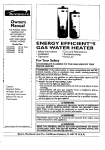
FOR POTABLEWATER
HEATING ONLY
NOT SUITABLEFOR
SPACEHEATING
NOT FOR USE IN
MOBILE HOMES
Model
L53.335816
153.335845
153.335862
153.335916
40
40
40
50
POWER
No.
Gal.
Gal. High Altitude L.R
GaL.L.R
Gal.
153.335942 50 Gal. High Altitude L.R
153.335962 50 Gal. L.R
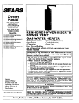
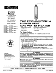
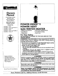
MISER
9
TM
POWER VENT
GAS WATER HEATER
• Safety Instructions
• Installation
• Operation
• Care and Maintenance
• Troubleshooting
• Parts List
For Your Safety
AN ODORANT
IS ADDED
WATER
HEATER
WARNING:
TO
If the information
THE
GAS
in these
lowed exactly, a fire or explosion
damage, personal injury or death•
USED
BY THIS
instructions
may result,
are not fol-
causing
____Do not store or use gasoline or other flammable
uids in the vicinity of this or any other appliance•
_-_/VHAT TO DO IF YOU SMELL GAS
property
vapors and liq-
_-=" Do not try to light any appliance.
• Do not touch any electrical switch; do not use any phone in your
building.
•
*
9
o-- • Immediately
call your gas supplier
from a neighbor
s phone.
Follow the gas supplier's]nstructions.
-_r If you can not reach your gas suppher, call the fire department.
--Installation
and service must be performed
serv,ce agency or the gas suppher.
Caution:
Read and Follow
by a qualified installer,
AWARNING
Improper installation, adjustment, alteration, service or maintenance
can cause DEATH, SERIOUS BODILY INJURY, OR PROPERTY DAMAGE. Refer to this manual for assistance or consult the local Sears
L Service Center or gas uti ty for further nformat on.
All Safety Rules and
Operating Instructions
Before First Use of
This Product.
Flammable
vapors may be drawn by air currents
•,WARNING
of the structure to this appliance.
Save this Manual for Future Reference.
Sears,
Roebuck
from
_WARNING
READ THE GENERAL SAFETY SECTION
BEGINNING
COVER AND THEN THIS ENTIRE MANUAL
BEFORE
OR OPERATING
THIS WATER HEATER.
and Co., Hoffman
Estates,
IL 60179
U.S.A.
other
areas
ON INSIDE
INSTALLING
t
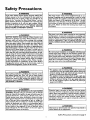
Safety Precautions
&`WARNIN__G
Improper installation, adjustment, alteration, service or
maintenance
can cause death, serious bodily injury, or
property
damage. Refer to this manual for assistance or
consult your local Sears Service Center for further
I information.
_,WARNING
WATER HEATERS EQUIPPED
FOR ONE TYPE GAS
ONLY: This water heater is equipped for one type gas
only. Check the model rating plate near the gas control
valve for the correct gas. DO NOT USE THIS WATER
HEATER WITH
ANY GAS OTHER THAN THE ONE
SHOWN
ON THE MODEL RATING PLATE. Failure to
use the correct gas can cause problems which can result in
DEATH,
SERIOUS BODILY INJURY, OR PROPERTY
;)AMAGE. If you have any questions or doubts consult
four gas supplier or local utility.
&`WARNING
INSTALLATIONS IN AREAS WHERE FLAMMABLE LIQUIDS (VAPORS) ARE LIKELY TO BE PRESENT OR
STORED (GARAGES, STORAGE, AND UTILITY AREAS
ETC): Flammable liquids (such as gasoline, solvents
propane (LP) or butane, etc.), all of which emit flammable
vapors, may be improperly stored or used in such areas.
The gaswater heater pilot light or main burner can ignite
such vapors. The resulting flashback and fire can cause
death or serious burns to anyone in the area, as well as
property damage.
If installation in such areas is your only option, then the
installation must be accomplished in a way that the pilot
flame and main burner flame are elevated from the floor
at least 18 inches. While this may reduce the chancesof
flammable vapors from a floor spill being ignited, gasoline
and other flammable substancesshouldnever be stored or
used in the same room or area containing a gas water
heater or other open flame or spark producingappliance.
qOTE: Flammable vapors may be drawn by air currents
from other areas of the structure to the appliance.
&`WARNING
f this water heater will be used in beauty shops, barber
shops, cleaning establishments, or self-service laundries
with dry cleaning equipment,
it is imperative that the
water heater or water heaters be installed so that combustion and ventilation air be taken from outside these
areas. Refer to the "Locating
The New Water Heater"
section of this manual and also the latest edition of the
National Fuel Gas Code, ANSI Z223.1, also referred to as
NFPA 54 for specifics provided concerning air required.
&`WARNING
A fire can start if combustible materials such as clothing, I
cleaning materials, or flammable liquids are placed against
or next to the water heater.
&,WARNING
At the time of manufacture this water heater was provided with a combination temperature-pressures
relief valve
certified by a nationally recognized
testing laboratory
that maintains periodic inspection of production of listed
equipment or materials, as meeting the requirements
for Relief Valves and Automatic Gas Shutoff Devices for
Hot Water Supply Systems, and the latest edition of
ANSI Z21.22 and the code requirements
of ASME. If
replaced, the valve must meet the requirements
of local
codes, but not less than a combination temperature and
pressure relief valve certified as meeting the requirements for Relief Valves and Automatic
Gas Shutoff
Devices for Hot Water Supply Systems, ANSI Z21.22 by
a nationally recognized testing laboratory that maintains
periodic inspection of production of listed equipment or
materials.
The valve must be marked with a maximum set pressure
not to exceed the marked hydrostatic working pressure
of the water heater (150 Ibs./sq. in.) and a discharge
capacity not |ess than the water heater input rate as
shown on the model rating plate. (Electric heaters watts divided by 1000 x 3415 equal BTU/Hr. rate.)
Your local jurisdictional authority, while mandating the
use of a temperature-pressure
relief valve complying
with ANSI Z21.22 and ASME, may require a valve model
different from the one furnished with the water heater.
Compliance with such local requirements
must be satisfied by the installer or end user of the water heater with
a locally prescribed temperature-pressure
relief valve
installed in the designated opening in the water heater in
place of the factory furnished valve.
For safe operation of the water heater, the refief valve
must not be removed from it's designated opening or
plugged.
The temperature-pressure
relief valve must be i_t_lled
directly into the fitting of the water heater _ignated
for the relief valve. Position tee valve nuw,w_:J_and pro.
vide tubing so that any discharg_ will exit only _vithin I
inches above, or at any distance below the s_ructura
floor. Be certain that no c_itl_any
live
electrical
part. The discharge oF_r_ust
not be
blocked or reduced in sli_n-d'eP'a_fe_nstances.
Excessive length, over 30 feef;_J: OJL_,_____.
s
than four
elbows can cause restriction
and redu_e_discharge
capacity of the valve.
- ....
,
No valve or other obstruction is to be placed_between
the relief valve and the tank::l_-m_mne'_t
tubing
directly to discharge drain unless a 6" air gap is provided.
To prevent bodily injury, hazard to life, or property damage, the relief valve must be allowed to discharge water
in quantities should circumstances demand. If the discharge pipe is not connected to a drain or other suitable
means, the water flow may cause property damage.
The Discharge Pipe:
• Must not be smaller in size than the outlet pipe size of
the valve, or have any reducing
couplings or other
restrictions.
• Must not be plugged or blocked.
• Must be of material listed for hot water distribution.
• Must be installed so as to allow complete drainage of
Must terminate at an adequate drain.
Must the
not temperature-pressurepipe.relief
have any valve between the relief
bothdischarge
valve, valve
and and
the
tank.
Safety Precautions
AWARNING
AWARNING
A gas water heater cannot operate properly without the
correct amount of air for combustion. Do not install in a
confined area such a closet, unless you provide air as
shown in the "Locating The New Water Heater" section.
This water heater must not be installed directly on carpeting. Carpeting must be protected by a metal or wood
panel beneath the appliance extending beyond the full
width and depth of the appliance by at least 3 inches
(76.2mm) in any direction, or if the appliance is installed
in an alcove or closet, the entire floor must be covered by
the panel. Failure to heed this warning may result in a
fire hazard.
Never obstruct the flow of ventilation air. If you have any
i doubts or questions at all call your gas company. Failure
to provide the proper amount of combustion air can result
in a fire or explosion and can cause DEATH, SERIOUS
BODILY INJURY, OR PROPERTY DAMAGE.
_,WARNING
The power vent water heater requires its own (separate)
venting system. It cannot be connected to an existing vent
pipe or chimney. It must be terminated horizontally to the
outdoors. Failure to properly install the venting system can
result in asphyxiation, a fire or explosion and can cause
DEATH, SERIOUS BODILY INJUR_, OR PROPERTY DAMAGE.
AWARNING
HOTTER
WATER CAN SCALD: Water heaters are
intended to produce hot water. Water heated to a ternperature which will satisfy clothes washing, dish washing,
and other sanitizing needs can scald and permanently
injure you upon contact. Some people are more likely to
be permanently injured by hot water than others. These
include the elderly, children, the infirm, or physically/mentally handicapped. If anyone using hot water in your home
fits into one of these groups or if there is a local code or
state law requiring a certain temperature water at the hot
water tap, then you must take special precautions. In addition to using the lowest possible temperature setting that
satisfies your hot water needs, a means such as a mixing
valve, should be used at the hot water taps used by these
people or at the water heater. Mixing valves are available
at plumbing supply or hardware stores. Follow manufacturers instructions for installation of the valves. Before
changing the factory setting on the thermostat, read the
"Temperature
Regulation" section in this manual.
&WARNING
No vent damper installation is compatible with this power
vented water heater design. No vent damper, whether it is
operated thermally or otherwise is to be installed on this
power vented w=ter heater. Alteration of any part of the fac, tory-furnished vent assembly could result in improper operation due to restriction of flue gases, spillage of flue gases
and may cause carbon monoxide poisoning.
_,WARNING
,The appliance and its individualshutoff valve must be disconnected from the gassupply piping system during any
pressure testing of the gas system at test pressures in
excessof I/2 poundper squareinch(3.5kPa).
• The appliance must be isolated from the gas supplypiping system by closingits individual manual shutoff valve
during any pressure testing of the gas supplypiping system at test pressures equal or lessthan I/2 pound per
squareinch (3.5kPa).
_,WARNING
Soot build-up indicates a problem that requires correction before further use. Turn "off" gas to water heater
and leave "off" until repairs are made, because failure to
correct the cause of the sooting can result in a fire or
explosion causing DEATH, SERIOUS BODILY INJURY,
OR PROPERTY DAMAGE.
AWARNING
AWARNING
Chemical vapor corrosion of the flue and vent system
may occur if air for combustion contains certain chemical
vapors. Spray can propellants, cleaning solvents, refrigerator and air conditioner
refrigerants,
swimming pool
chemicals, calcium and sodium chloride, waxes, bleach,
and process chemicals are typical compounds which are
potentially corrosive.
BEFORE LIGHTING
[PROPANE
(L.P.) GAS WATER
HEATERS]: Propane (L.R) gas is heavier than air. Should
there be a leak in the system, the gas will settle near the
ground. Basements, crawl spaces, skirted areas under
mobile homes (even when ventilated), closets and areas
below ground level will serve as pockets for the accumulation of this gas. Before attempting to light or relight the
water heater's pilot or turning on a nearby electrical light
switch, be absolutely sure there is no accumulated gas in
the area. Search for odor of gas by sniffing at ground level
in the vicinity of the appliance. If odor is detected, follow
steps indicated at "For Your Safety" on the cover page of
:his manual then leave the premises.
AWARNING
Obstructed or deteriorated vent systems may present a
serious health risk or asphyxiation.
Safety Precautions continued on page 4.
3
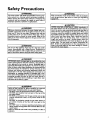
Safety
Precautions
_,WARNING
I
The water heater wi_talled
must be prep- I
erly vented to a chimney which terminates
outdoors. I
Never operate the water heater unless it is vented to the
outdoors and has adequate air supply to avoid risks of
improper operation, explosion or asphyxiation.
_WARNING
Vent termination must not be within 4 feet of any items
such as gas meters, gas valves or other gas regulating
equipment.
ACAUTION
AWARNING
Hinimum clearances between the water heater and combustible construction are 0" at the sides and rear, 5" at the
front, and 0" from the vent pipe. Clearance from the top
of the jacket is 14" on most models. Note that a lesser
dimension may be allowed on some models. Refer to the
label on the water heater adjacent to the gas control valve
for all clearances.
•,WARNING
Do not
water.
inspect
part of
--1
use this appliance if any part of it has been under I
Immediately
call a Sears Service Technician to I
the appliance and to replace the gas control or any I
the burner system which has been under water.
|
_,WARNING
HYDROGEN GAS: Hydrogen gas can be produced in a hot
water system that has not been used for a long period of
time (generally two weeks or more). Hydrogen gas is
extremely flammable and explosive. To prevent the possibility of injury under these conditions, we recommend the
hot water faucet be opened for several minutes at the
kitchen sink before any electrical appliances which are
connected to the hot water system are used (such as a
dishwasher or washing machine). If hydrogen gas is present, there will probably be an unusual sound similar to air
escaping through the pipe as the hot water faucet is
opened. There must be no smoking or open flame near
the faucet at the time it is open.
AWARNING
INSULATING
JACKETS: When installing an external
water heater insulation jacket on a gas water heater:
• DO NOT cover the temperature-pressure
relief valve.
• DO NOT put insulation over any part of the top of the
gas water heater.
• DO NOT put insulation over the gas control valve or gas
control valve/burner cover, or any access areas to the
burner.
• DO NOT let insulation around the gas water heater to
get within 8 inches of the floor (air must get to the
burner).
• DO NOT cover or remove operating instructions, and
safety related warning labels and materials affixed to the
water heater.
Failure to heed this will result in the possibility of a fire or
explosion.
WATER HEATERS EVENTUALLY
LEAK: Installation of
the water heater must be accomplished in such a manner
that if the tank or any connections should leak, the flow of
water will not cause damage to the structure. When such
locations cannot be avoided, a suitable drain pan should
be installed under the water heater. Drain pans are available at your local Sears store. Such a drain pan must be
not greater than 11/2 inches deep, have a minimum
length and width of at least 2 inches greater than the
water heater dimensions and must be piped to an adequate drain. The pan must not restrict combustion air
flow. Under no circumstances is the manufacturer
or
Sears to be held liable for any water damage in connection with this water heater.
I
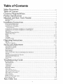
Table of Contents
cc...-..oal_y
Precautions ............................................................................................................................................
2-4
Table of Contents .................................................................................................
5
Customer
Responsibilities
...................................................................................................
6
Product Specifications ..............................................................................................
6
Materials and Basic Tools Needed ..........................................................................
7
Materials Needed ......................................................................................................................................................................
Basic Tools ................................................................................................................................................................................
Installation
Instructions
.................................................................................................
8-2o
Removing the Old Water Heater ...............................................................................................................................................
Locating the New Water Heater ..........................................................................................................................................
Combustion Air and Ventilation .............................................................................................................................................
Venting Clearances .............................................................................................................................................................
Combustion Air and Ventilation for Appliances in Unconfined Spaces ...................................................................................
Combustion Air and Ventilation for Appliances in Confined Spaces .......................................................................................
Water Piping ...........................................................................................................................................................................
Temperature-Pressure
Relief Valve ...........................................................................................................................................
Filling the Water Heater ..........................................................................................................................................................
Wiring ...............................................................................................................................................................................
Venting ..............................................................................................................................................................................
Gas Piping ..............................................................................................................................................................................
Installation Checklist ..............................................................................................................................................................
Operating
Instructions
7
7
8
9-10
10
10
11
11
12
13
14
14-15
15-18
19
20
...................................................................................................
21-24
Lighting .............................................................................................................................................................................
Temperature
Regulation ..........................................................................................................................................................
22-23
24
Service and Adjustment ...........................................................................................
25-27
Tank {Sediment) Cleaning ......................................................................................................................................................
Venting System Inspection ......................................................................................................................................................
Oiling Instructions ..................................................................................................................................................................
Burner Inspection ...................................................................................................................................................................
Burner Cleaning .....................................................................................................................................................................
L.P. Gas Control Valve & Burner Assembly Replacement Information ....................................................................................
Draining .................................................................................................................................................................................
Temperature-Pressure
Relief Valve Operation ..........................................................................................................................
Drain Valve Washer Replacement ...........................................................................................................................................
Housekeeping .........................................................................................................................................................................
Service ....................................................................................................................................................................................
Troubleshooting
25
25
25
25
25
26
26
26
27
27
27
Guide .............................................................................................
28-35
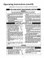
Start Up Conditions ..................................................................................................................................................................
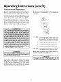
Thermal Expansion .................................................................................................................................................................
Strange Sounds .......................................................................................................................................................................
Condensation
.........................................................................................................................................................................
Smoke/Odor
...........................................................................................................................................................................
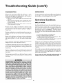
Operational
Conditions .......................................................................................................................................................
Smelly Water ...........................................................................................................................................................................
"Air" in Hot Water Faucets .....................................................................................................................................................
28
28
28
29
29
29-30
29
30
High Temperature Shut off System .........................................................................................................................................
Not Enough or No Hot Water ................................................................................................................................................
Water Is Too Hot ....................................................................................................................................................................
30
30
30
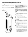
laeakage Checkpoints ................................................................................................................................................................
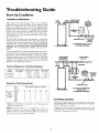
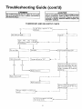
Thermostat
and Gas Supply Check ...........................................................................................................................................
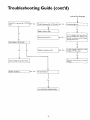
Electrical System Check .......................................................................................................................................................
3I
32
33-35
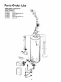
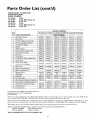
Parts Order List ....................................................................................................
36-39
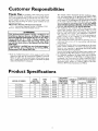
Customer
Responsibilities
Thank You
for purchasing a Sears water heater. Properly
instaRled and maintained, it should give you years of trouble free service. If you should decide that you want the new water heater professionally installed by Sears call the local Sears Service Center or any
Sears store. They will arrange for prompt, quality installation by Sears
authorized contractors.
Abbreviations
Found In This Instruction
Manual
I.A.S. - International
Approval Services, A Division of CSA
A.N.S.I. - American National Standards Ins6tute
•
AWARNING
This gas-fired water heater is design certified
by the
International Approval Services, A Division of CSA under
American National Standard/CSA Standard for Gas Water
Heaters ANS Z21.10.1 • CSA 4.1 (latest edition). The
installation must conform with this manual, Local Codes
and with the latest edition of the National Fuel Gas Code,
ANSI Z223.1.
This publication is available from your local government or
_ublic library,
gas company,
or by writing
NFPA,
Batterymarch Park, Quincy, MA 02269.
• Read the "Safety Precautions" section, pages 2 and 3 of this
manual first and then the entire manualcarefully. If you don't
follow the safety rules, the water heater will not operate properl)_ It could cause DEATH, SERIOUS BODILY INJURY
AND/OR PROPERTY DAMAGE.
Product
•
•
•
This manual contains instructions for the installation, operation, and maintenance of the gas-fired water heater. It also
contains warnings through out the manual that you must read
and be aware of. All warnings and all instructions are essential
to the proper operation of the water heater and your safety.
,_nce we cannot put everything on the first few pages, READ
HE ENTIRE MANUAL BEFORE ATTEMPTING TO
INSTALL OR OPERATE THE WATER HEATER.
The installation must conform with the instructions in this
manual; [_as company rules; and Local Codes, or in the
absence otLocal Codes, with the latest edition of the National
Fuel Gas code, ANSI Z223.1, also referred to as NFPA 54.
This publication is available from your local government or
public library or gas company" or by writing NFPA,
Batterymarch Park, Quincy, MA 02269.
lfafter reading this manual you have any questions or do not
understand any portion of the instructions, call the Sears
Service Center.
Carefully plan the place where you are going to put the water
heater. Correct combustion, vent action, and vent pipe installation are very iraportant in preventing death from possible
carbon monoxide poisoning and fires.
Examine the location to ensure the water heater complies with
the "Locating the New Water Heater" section in this manual.
For California installation this water heater must be braced,
anchored, or strapped to avoid falling or moving during an
earthquake. See instructions for correct installation procedures. Instructions may be obtained from your local dealer,
wholesaler, public utilities or California Office of the State
Architect, 400 P Street, Sacramento, CA 95814.
Specifications
153.335816
40
TYPE
OF
GAS
NATURAL
40,000
RECOVERY
RATE GALS.
PER HOUR
@ 90°F RISE
40.9
153.335845
40
PROPANE
40,000
40.9
3"
18"
6O"
153.335862
40
PROPANE
40,000
40.9
3"
18"
6O"
153.335916
50
NATURAL
40,000
40.9
3"
20"
59½"
153.335942
50
PROPANE
40,000
40.9
3"
20"
59W'
153.335962
50
PROPANE
40,000
40.9
y'
20"
59_"
MODEL
NUMBER
TANK
CAPACITY
IN GALLONS
B.ZU.
RATE
MINIMUM
VENT
PIPE
3"
DIMENSIONS IN INCHES
HEIGHT
TO
DIAMETER JACKETTOP
18"
60"
Materials
Materials
and Basic Tools Needed
Needed
To simplify the installation Sears has available the installation
parts shown below. You may or may not need all of these materials, depending on your type of installation.
WATER HEATER STAND 24"x24"x18"
FOR USE WITH WATER HEATERS
INSTALLED IN RESiDENTiAL
GARAGES HAVING A DIAMETER 24"
OR LESS AND A RATED CAPACITY 75
GALLONS OR LESS
Gas
Water Heater
I Installation
Kit
_
I
EXPANSION
TANKS FOR
THERMAL EXPANSION
CONDITIONS
AVAILABLE IN
2 GALLON AND 5 GALLON
CAPACITY THROUGH
LOCAL SEARS STORE OR
SERVICE CENTERS
PVC VENT
WATER HEATER
INSTALLATION
KIT WITH
FLEXIBLE CONNECTORS
FOR 3/4" GALVANIZED
OR
I/2"COPPER PLUMBING
PVC VENT
FLEXIBLE WATER
GAS CONNECTOR
FITTINGS
HEATER
WITH
ELBOW
EXTENSION
WATER HEATER HEAT
TRAPS HELP REDUCE HEAT
LOSS DUE TO THERMAL
SYPHONING
DRAIN PANS
AVAILABLE IN 20" DIAMETER FOR
WATER HEATERS HAVING A DIAMETER 18" OR LESS AND AVAILABLE IN
28" DIAMETER FOR WATER HEATERS
HAVING A DIAMETER 26" OR LESS
Basic Tools
You may or may not need
type of installation.
These
Sears store,
all of these tools, depending
on your
tools can be purchased at your local
• Pipe Wrenches (2) 14"
• Screwdriver
• Tin Snips
• 6 Foot Tape of Folding Rule
• Garden Hose
• Drill
• Pipe dope or Teflon Tape
ADDITIONAL
TOOLS NEEDED
WHEN SWEAT SOLDERING
• Tubing Cutters or Hacksaw
• Propane Torch
• Soft Solder
• Solder Flux
_ Wire
EmeryCIoth
Brushes
HACKSAW
GARDEN
HOSE
6 FOOT TAPE
SLOT-HEAD
SCREWDRIVER
PiPE
WRENCH
314" WIRE BRUSH
112" WiRE BRUSH
PHILLIPS
SCREWDRIVER
PROPANE
TORCH
TIN SNIPS
ROLL OF LEAD FREE
SOFT SOLDER
ROLL OF TEFLON TAPE
(USE ONLY ON WATER
CONNECTIONS)
PIPE DOPE (SQUEEZE TUBE)
(USE FOR WATER AND
GAS CONNECTIONS)
DRILL
ROLL OF EMERY
CLOTH
SOLDER FLUX
TUBING
CUTTER
Installation
Removing
Instructions
the Old Water
Heater
Turn "OFF" the gas supply to the water heater.
Disconnect
the vent pipe from the draft hood where
they connect to the water heater. In most installations
the vent pipe can be lifted off after any screw or other
attached
devices are removed. Dispose of the draft
hood. The new water heater has the draft hood which
must be used for proper operation.
_,WARNING
If the main gas line shutoff serving all gas appliances is I
used, also shut "off" the gas at each appliance. Leave all
gasappliances shut "off" until the water heater installation
s comp ete.
®
®
a,
®
Turn lIOF F" the water to the water
heater. Some installations
require that
the water be turned off to the entire
house.
If you have copper piping to the water
heater, the two copper water pipes can
be cut with a hacksaw approximately
four inches away from where they connect to the water heater. This will avoid
cutting
off the pipes too short.
Additional cuts can be made later if necessary. Disconnect the temperature-pressure relief valve drain line. When the
water heater is drained, disconnect the
hose from the drain valve. Close the
drain valve. The water heater is now
completely disconnected and ready to be
removed.
®
QCheck
again to make sure the gas supply
is "OFF" to the water heater. Then disconnect the gas supply connection from
the gas control valve.
Q
Attach
valve
drain
drain
faucet
water
a hose to the water
heater drain
and put the other end in a floor
or outdoors. Open the water heater
valve. Open a nearby hot water
which will relieve pressure in the
heater and speed draining.
WARNIN
G
The water passing out of the drain valve may be extremely I
hot. To avoid being scalded, make sure all connections are I
tight and that the water flow is directed away from any
person.
®h"
If you have galvanized pipe to the water
heater, loosen the two galvanized pipes
with a pipe wrench at the union in each
line. Also disconnect the piping remaining to the water heater. These pieces
should be saved since they may be needed when reconnecting the new water
heater. Disconnect the temperature-pressure relief valve drain line. When the
water heater is drained, disconnect the
hose from the drain valve. Close the
drain valve. The water heater is now
completely disconnected and ready to be
removed.
A CAUTION
]
Mineral buildup or sediment may have accumulated in the I
old water heater. This causes the water heater to be much I
heavier than normal and this residue, if spilled out, could
cause staining.
Installation
Instructions
Locating the New Water
Heater
5. The location selection must provide adequate clearances for
servicing and proper operation of the water heater.
You should carefully choose an indoor location for the new water
heater, because the placement is a very important consideration
for the safety of the occupants in the building and for the most
economical use of the appliance. This water heater is not for
use in mobile homes or outdoor installation.
Whether
replacing an old water heater or putting the water
heater in a new location, the following critical points must be
observed.
1. The location selected sbould be indoors as close as practical
to the vent ternfination
point, and as centralized with the
water piping system as possible. The water heater, as a[l water
heaters, will eventually leak. Do not install without adequate
drainage provisions where water flow will cause damage.
2.
The vent piping cannot exceed a total of 35
vertical and horizontal runs and have no more
it cannot slope downward and horizontal runs
foot rise. All horizontal runs require adequate
feet intervals.
feet inchlding
than 3 elbows.
require/"
per
support at 3½
3.
The water heater requires its own (separate) venting system.
It cannot be connected to an existing vent pipe or chimney.
It must terminate horizontally to the outdoors.
Whenever
possible terminate the vent on the leaward side of the building. NOTE: Condensation
may be created, at times, as the
combustion
gases exit the vent cap and discoloration
of
surfaces in proximity
to the vent cap may occur.
_IWARNING
The power vent water heater requires itsown (separate) venting
system. It cannot be connected to an existingvent pipe or chimney. It must be terminated horizontally to the outdoors. Failureto
properly installthe venting systemcan result in asphyxiation,a fire
or explosion and can causeDEATH, SERIOUS BODILY INJUR_,
OR PROPERTY DAMAGE.
4.
The water beater comes equipped with a 5 foot power cord
which can be used to connect
to a 110/120
volt power
source if(l) local codes allow, and (2) there is a three prong
receptacle available.
IIWARNING
Do not useanextensioncord. If there isnot a suitablerecepta. I
tie and/orlocalcodesprohibituseof a powercord,field wiring
must be provded.
ACAUTION
WATER HEATERS EVENTUALLY LEAK: Installation of the
water heater must be accomplished in such a manner that if
the tank or any connections should leak, the flow of water
will not cause damage to the structure. When such locations
cannot be avoided, a suitable drain pan should be installed
under the water heater. Drain pans are available at your
local Sears store. Such a drain pan must be not greater than
1½ inches deep, have a minimum length and width of at least
2 inches greater than the water heater dimensions and must
be piped to an adequate drain. The pan must not restrict
combustion air flow. Under no circumstances is the manufacturer or Sears to be held liable for any water damage in
connection with this water heater.
IIWARNING
INSTALLATIONS IN AREAS WHERE FLAMMABLE LIQUIDS
'VAPORS) ARE LIKELY TO BE PRESENT OR STORED
'GARAGES, STORAGE, AND UTILITY
AREAS, ETC):
klammable liquids (such as gasoline, solvents, propane (LP) or
butane, etc.), all of which emit flammable vapors, may be
improperly stored or used in suchareas. The gas water heater
pilot light or main burner can ignite such vapors. The resulting
flashbackand fire can cause death or serious bums to anyone m
the area, as well as property damage.
If installation in such areas is your only option, then the installa.
tion must be accomplished in a way that the pilot flame and
main burner flame are elevated from the floor at least 18 inches.
While this may reduce the chancesof flammable vapors from a
floor spill being ignited,gasolineand other flammable substances
shouldnever be stored or used in the same room or area conraining a gas water heater or other open flame or spark producing appliance.
NOTE: Flammable vapors may be drawn by air currents from
other areas of the structure to the appliance.
•_ WARNING
Propell_nts of aerosol sprays and volatile compounds, (cleaners, chlorine based chemicals, refrigerants, etc.) in addition to
being highly flammable in many cases,will also change to corrosive hydrochloric acid when exposed to the combustion
products of the water heater. The results can be hazardous,
and also cause product failure.
AWARNING
This water heater must not be installed directly on carpeting.
Carpeting must be protected by a metal or wood panel
beneath the appliance extending beyond the full width and
depth of the appliance by at least 3 inches (76.2mm) in any
direction, or if the appliance is installed in an alcove or closet,
the entire floor must be covered by the panel. Failure to heed
this warning may result in a fire hazard.
AWARNING
Minimum clearances between the water heater and combustible construction are 0" at the sides and rear, 5" at the
front, and fl" from the vent pipe. Clearance from the top of the
jacket is 14"on most models. Note that a lesserdimension may
be allowed on some models. Refer to the label on the water
heater adjacent to the gas control valve for all clearances.
J2"_
_IIN
I)" MIN
VEN TILATION
AIR
OPENINGS
TOP VIEW II" MIN
OF CLOSET
WITHOUT
DOOR
_'
Figure
I ]
MAX.
_
10P VIEW
OF CLOSET
Wl]H
DOOR
AlE DUCT
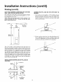
Installation
Instructions
(cont'd)
IIWARNING
from
any overhang
A gaswater heater cannotoperate properlywithout the correct amount of air for combustion.Do not install in a confined area such a closet, unlessyou provide air as shownin
the "Locating The New Water Heater" section. Never
obstruct the flow of ventilationair. If you haveany doubtsor
questionsat all, callyour gascompany.Failureto providethe
proper amountof combustionair canresultin a fire or explosionand can causeDEATH, SERIOUS BODILY INJUR_,OR
PROPERTYDAMAGE.
of Flue
li WARNING
Figure 2 ]
If this water heater willbe usedin beautyshops,barber shops,
cleaning establishments,or self-servicelaundrieswith dry
cleaningequipment, it is imperativethat the water heater or
water heaters be installedsothat combustionand ventilation
air be taken from outsidetheseareas. Referto the "Locating
The New Water Heater" sectionof this manualand also the
latest editionof the NationalFuelGasCode,ANSI Z223.1,also
referred to as NFPA 54 for specificsprovidedconcerningair
required.
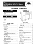
Combustion
Air and Ventilation
TERMINAL
When determining the installation location for apower vent
water heater, snow accumulation and drifting shouldbe considered in areas where applicable.
VENTING
0" clearance for 3" PVC, ABSor CPVC Schedule 40 vent piping
from combustible surfaces.
•
•
12" minimum from the ground, 18" ceilingoverhangs.Figure2.
The Power Vent outlet terminal shall terminate at least 3 feet above
any forcedair inlet locatedwithin 10 feet. Figure3a.
The PowerVent outlet terminal shall terminate at least4 feet below,
4 feet horizontallyfrom or 1 foot aboveany door, window or gravity
air inlet into the building.Figure3a.
18" minimum in all directions from any obstruction that may
interfere.Figure3b.
18" minimum from other gravityor natural appliance outlet vents
when directlyaboveor 135° to either sideof center line. Figure3c.
36" minimum from any outlet vents when directlybelow or 45° to
either sideof center line. Figure3c.
36" minimum in all directionsfrom any other forced air appliance
outlet vent. Figure3c.
The location selection must provide clearances for servicing and
proper operation of the water heater.Figure4.
Vent termination must not be within 4 feet of any itemssuch as gas
meters,gas valvesor other gas regulatingequipment.
The venting system must be installed in a manner which allows
inspection of the installationof the venting pipes and joints as well
as periodic inspection after installation as required by ANSI
Standards.
•
•
•
•
•
•
•
•
INLET
CLEARANCES
•
12" min.
Figure
3a]
S
L_
VENT TERMINAL
IB" TO WALL OR OTHER
OBSTRUCTIONS THAT
MAY INTERFERE WITH
VENTING.
I E" MIN,
rF
[F,gu.
3b]
VENT TERMINAL
CORNER OF BUILDING
*THIS DIMENSION IS
POWER
VENT
__
TERHINAL
_
_-- _
-
J_
_\
_
_ _"
_
_j_
_B"*/'
"-
_
_
36,_
'
_--'-
_
_
_
INCREASED TO 36" WHEN
_THE
VENT OUTLET IS FOR A
FORCED VENT APPLIANCE
_-DIRECTVENTOR
GRAVITY VENTED
\ _
APPLIANCE
45°
[Figure3c
I
Must
iI WARNING
ANY OTHER OUTLET VENT
maintain
adequate service
and maintenance
Ventterminationmust not bewithin4 feet of anyitemssuchas
gasmeters,gasvalvesor other gasregulating equipment.
ibility.
iIWARNING
Range of degrees
Failureto haverequired clearancesbetweenwater heater and
combust b e mater al w resut n a fire hazard.
[ Figure 4 ]
10
vent
pipe
installation.
available
for
Installation
Instructions
(cont'd)
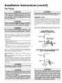
Combustion
Air and Ventilation
for Appliances Located in
Unconfined Spaces
Unconfined Space is a space whose volume is not less than 50 cubic
feet per 1,000 Btu per hour of the aggregate input rating of all appliances installed in that space. Rooms communicating directly with the
space in which the appliances are installed, through openings not fur_
nished with doors, are considered a part of the unconfined space.
In unconfined spaces in buildings, infiltration may be adequate to
provide air for combustion, ventilation and dilution of flue gases.
However, in buildings of tight construction (for example, weather
stripping, heavily insulated, caulked, vapor barrier, etc.), additional air
may need to be ])rovided using the methods described in Combustion
Air and Ventilation for Appliances Located in Confined Spaces.
1. When directly communicating with the outdoors, each opening
shall have a minintum free area of 1 square inch per 4,000 BTU
per hour of total input rating of all equipment in the enclosure.
(See Figure 6.)
2. When communicating with the outdoors through vertical ducts,
each opening shall have a minimum free area of 1 square inch
per 4,000 BTU per hour of total input rating of all equipment in
the enclosure. (See Figure 7.)
_NTILAT_N
LOUVERS
{_ch cad o_a_m)
AIR OUTLEt
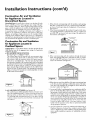
Combustion Air and Ventilation
for Appliances Located in
Confined Spaces
_TDOO_sINLET
AIn DUCT
_VEN_
Confined Space is a space whose volume is less than 50 cubic feet per
1,000 Btu per hour of the aggregate input rating of all appliances
installed in that space.
a. ALL AIR FROM INSIDE BUILDINGS:
(See Page 8 Figure 1, and Figure 5 below)
The confined space shall be provided with two permanent openings communicating directly with an additional room(s) of sufficient volume so that the combined volume of all spaces meets the
criteria for an unconfined space. The total input of all gas utilization equipment installed in the combined space shall be considered
in making this determination. Each opening shall have a minimum
free area of one square inch per 1,000 BTU per hour of the total
input rating of all gas utilization equipment in the confined space,
but not less than 100 square inches. One opening shall commence
within 12 inches of the top and one commencing within 12 inches
of the bottom of the enclosure.
TO
.......... t,,
',',',',',',',%'!
Figure
7 ]
i_ll:J
3. When communicating with the outdoors through horizontal
ducts, each opening shall have a minimum free area of 1 square
inch per 2,000 BTU per hour of total input rating of all equipment in the enclosure. (See Figure 8.)
_VENTTO
OUTDOORS
OUTLET _1_ DUCT
WATER
HE_TE_
Figure
iiirlll,,,,,llll
,_,,,,_,,,rll_llll
4. When ducts are used, they shall be of the same cross-sectionalarea
as the free area of the openings to which they connect. The minimum short side dimension of rectangular air ducts shall not be
lessthan 3 inches. (See Figure 8.)
_L
Figure 5 I
8 ]
5. Louvers and Grilles:In calculating free area, consideration shall be
given to the blocking effect of louvers, grilles or screens protecting openings. Screens used shall not be smaller than¼ inch mesh.
If the free area through a design of louver or grille is known, it
should be used in calculating the size opening required to provide
the free area specified. If the design and free area is not known, it
may be assumed that wood louvers will be 20-25 percent free area
and metal louvers and grilles wi!l have 60-75 percent free area.
Louvers and grilles shallbe fixed in the open _osition or interlocked with the equipment so that they are opened automatically
during equipment operation.
b. ALL AIR FROM OUTDOORS:
(see Figures 6-8)
The confined space shall be provided with two permanent openings, one commencing within 12 inches of the top and one commencing within 12 inches from the bottom of the enclosure.
The openings shall communicate directly, or by ducts, with the
outdoors or spaces (crawl or attic) that freely communicate with
the outdoors.
, ii
6. Special Conditions Created by Mechanical Exhausting or
Fireplaces:Operation of exhaust fans, ventilation systems, clothes
dryers or fireplacesmay create conditions requiring special attention to avoid unsatisfactory operation of installed gas utilization
equipment.
j Figure
6 ]
\
/
_Utlt_rlO_LOUVE.S
11
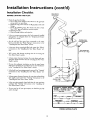
Installation
Water
Instructions
(cont'd)
Piping
AWARNING
2. Look at the top cover of the water heater. The cold water
inlet is marked cold. Put two or three turns of teflon tape
around the threaded end of the threaded-to-sweat coupling
and around both ends oiCthe X" threaded nipple. Using flexible connectors, connect the cold water pipe to the coldwater
inlet of the water heater.
HOTTER WATER CAN SCALD: Water heaters are intended to
Jmduce hot water. Water heated to a temperature which will
satisfyclothes washing, dishwashing, and other sanitizing needs
can scald and permanently injure you upon contact. Some peefie are more likely to be permanently injured by hot water than
others. These includethe elderly, children,the infirm, or physically/mentally handicapped. If anyone usinghot water in your home
fits into one of these groups or if there is a localcode or state law
requiring a certain temperature water at the hot water tap, then
_u must take special precautions.In addition to usingthe lowest
mssible temperature setting that satisfiesyour hot water needs,
a means such as a mixing valve, shouldbe used at the hot water
taps used by these people or at the water heater. Mixing valves
are availableat plumbing supplyor hardware stores.Follow man.
ufacturers instructions for installation of the valves. Before
changing the factory setting on the thermostat, read the
"Temperature Regulation" section in this manual.
NOTE: This water heater is insulated to minimize heat
loss from the tank. Further reduction in heat loss can be
accomplished by insulating the hot water lines from the
water heater.
INSTALLATION
COMPLETED
SEARS INSTALLATION
USING
KIT
COLD INLET
WATERLINE
THREADED TO
SWEAT COUPLING
This water heater shall not be connected to any heating systems
or component(s)
used with a non-potable water heating appliance.
THREADED TO
SWEAT COUPLING
If a water heater is installed in a closed water supply system;
such as one having a back-flow preventer, check valve, water
meter with a check valve, etc.., in the cold water supply; means
shall be provided to control thermal expansion. Contact the
local utility or local Sears Service Center on how to control this
situation.
SHUTOFF
VALVE
3!4" THREADED
NIPPLE
TEMPERATUREPRESSURERELIEF
VALVE
HOT OUTLET
TO HOUSE
NOTE: To protect against untimely corrosion
of hot and
cold water fittings, it is strongly recommended
that dielectric unions or couplings
be installed
on this water heater
when connected to copper pipe.
NIPPLE
The illustration shows the attachment of the water piping to the
water heater. The water heater is equipped with / inch water
connections.
DISCHARGE PIPE
(Do not cap or plug)
NOTE: If using copper tubing, solder tubing to an adapter
before attaching the adapter to the cold water inlet connection. Do not solder the cold water supply line directly to the
cold water inlet or it will harm the dip tube.
PROVIDE A 6" AIR
GAP BETVVEEN THE
END OF THE
DISCHARGE
PIPE
AND DRAIN
1. Look at the top cover of the water heater. "I'he hot water outlet is
marked hot. Put two or three turns of teflon tape around the
threaded end of the threaded-to-sweat coupling and around both
ends of the X" th eaded npple. Us'ng flex'ble connectors, con
nect the hot water pipe to the hot water outlet on the water
heater.
12
Installation
Instructions
Temperature-Pressure
(cont'd)
Relief Valve
_,WARNING
_,WARNING
The temperature-pressure
relief valve must be manually
operated at least once a year. Caution should be taken to
ensure that (1) no one is in front of or around the outlet of
the temperature-pressure relief valve discharge line, and (2)
the water manually discharged will not cause any bodily
injury or property damage because the water may be
extremely hot.
At the time of manufacture this water heater was provided
with a combination temperature-pressures relief valve certified
by a nationally recognized testing laboratory that maintains
Jerlodlc inspection of production of listed equipment or materials_ as meeting the requirements
for Relief Valves and
Automatic Gas Shutoff Devicesfor Hot Water Supply Systems,
and the latest edition of ANSI Z21.22 and the code requirements of ASME. If replaced, the valve must meet the require.
ments of local codes_but not lessthan a combination temperature and pressure relief valve certified as meeting the requirements for Relief Valves and Automatic Gas Shutoff Devices for
Hot Water Supply Systems, ANSI Z21.22 by a nationally recognized testing laboratory that maintains periodic inspection of
_roduction of listed equipment or materials.
The valve must he marked with a maximum set pressure not
to exceed the marked hydrostatic working pressure of the
water heater (150 Ibs.lsq.in.) and a discharge capacity not less
than the water heater input rate as shown on the model rating
plate. (Electric heaters - watts divided by 1000 x 3415 equal
BTU/Hr. rate.)
Your local jurisdictional authority, while mandating the use of a
temperature-pressure relief valve complying with ANSI Z21.22
and ASME, may require a valve model different from the one
furnishedwith the water heater.
Compliance with such local requirements must be satisfied by
the installer or end user of the water heater with a locally prescribed temperature-pressure relief valve installed in the designated opening in the water heater in place of the factory furnished valve.
For safe operation of the water heater, the relief valve must not
be removed from it's designatedopening or plugged.
The temperature-pressure relief valve must be installed directly
into the fitting of the water heater designatedfor the relief valve.
Position the valve downward and provide tubing sothat any discharge will exit only within 6 inches above, or at any distance
below the structural floor. Be certain that no contact is made
with any live electrical part. The dischargeopening must not be
blocked or reduced in size under any circumstances. Excessive
length, ever 30 feet, or use of more than four elbows can cause
restriction and reduce the dischargecapacity of the valve.
No valve or other obstruction is to be placed between the relief
valve and the tank. Do not connect tubing directly to discharge
drain unlessa 6" air gap is provided.To prevent bodily injury, haz.
ard to life, or property damage, the relief valve must be allowed
to dischargewater in quantities shouldcircumstancesdemand. If
the discharge pipe is not connected to a drain or other suitable
means, the water flow may causeproperty damage.
The Discharge Pipe:
Must not be smaller in size than the outlet pipe size of the
valve, or haveany reducing couplingsor other restrictions.
Must not be plugged or blocked.
Must be of material listed for hot water distribution.
Must be installed so as to allow complete drainage of both
the temperature-pressure relief valve, and the discharge
pipe.
Must terminate at an adequate drain.
Must not have any valve between the relief valve and tank.
If after manually operating the valve, it fails to completely
reset and continues to release water, immediately close the
cold water inlet to the water heater, follow the draining
instructions, and replace the temperature-pressure
relief
valve with a new one.
TEMPERATURE-PRESSURE
RELIEF
VALVE
HOT
/
DISCHARGE PIPE
(Do not cap or plug)
PROVIDE A 6" AIR
GAP BETWEEN THE
END OF THE
DISCHARGE PIPE
AND DRAIN
RELIEFVALVE OPENING
At the time of manufacture, this water heater was provided with a combination ternperature-pressure relief valve listed as complying with the standard for relief valves and
automatic gas shut-off devices for hot water supply systems, ANSI Z21.22. For safe
operation of the water heater, the relief valve must not be removed from its designated
point of installation or plugged
Your local jurisdictional authorlty, while mandating the use of a temperature-pressure
relief valve complying with ANSI Z21 22 and ASME, may require a valve model different
from the one furnished with the water heater.
Compliance with such local requirements must be satisfied by the installer or end user
of the water heater with a locally prescribed temperature-pressure relief valve installed
in the designated opening in the water heateE
See manual heading -"Temperature-Pressure Relief Valves" for installation and maintenance of relief valve, discharge line, andother safety precaut;ons
13
Installation
Instructions
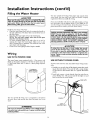
Filling the Water
Heater
You must provide all wiring of the proper size outside of the
water heater. You must obey local codes and electric company
requirements when you install this wiring.
ACAUTION
Never use this water heater unless it is completely filled with
water. To prevent damage to the tank, the tank must be filled
with water. Water must flow from the hot water faucet
If you are not familiar with electric codes and practices, or if you
have any doubt, even the slightest doubt, in your ability to connect the wiring to this water beater, obtain the service of a competent electrician or contact your local electric utility.
before turn ng ON" gas to the water heater.
To fill the water heater with water:
Close the water beater drain valve by turning the handle to
the right (clockwise). The drain valve is on the lower front of
the water heater.
Open the cold water supply valve to the water heater.
NOTE: The cold water supply valve must be left open
when the water heater is in use.
To insure complete filling of the tank, allow air to exit by
opening the nearest hot water faucet. Allow water to run
until a constant flow is obtained. This will let air out of the
water heater and the piping.
Check all new water piping for leaks. Repair as needed.
_,WARNING
WATER HEATERS EQUIPPED FOR ONE TYPE VOLTAGE
ONLY:Thiswater heaterisequippedfor 1101120voltsonly.DO
NOT USE THIS WATER HEATER WITH ANY VOLTAGE
OTHER THAN THE ONE SHOWN ABOVE,Failureto usethe
correctvoltagecancauseproblemswhichcanresult in DEATH,
SERIOUS BODILY INJURYOR PROPERTYDAMAGE. If you
haveanyquestionsor doubtsconsultyourelectriccompany.
& CAUTION
If wiling from the fuse box or circuit breaker box was aluminum for the old water heater, replace it with copper wire.
If you wish to reuse the existing aluminum wire, have the
connection at the water heater made by a competent electrician. Contact a local electrical contractor andlor the local
electric utility.
Wiring
USE
WITH
POWER
CORD
USE WITHOUT
The water heater comes equipped with a 5 foot power cord
which can be used to connect to a 110/120 volt power source if,
(1) local codes allow, and (2) there is a three prong receptacle
available.
\\
\\
\ \
\\
NN
\ \
\\
\\
\\
\\
\\
\\
\ \
\ \
\\
(cont'd)
POWER
CORD
If power cord cannot be used, then follow these wiring instructions.
l. Provide a way to easily shut off the electric power when working on the water heater. This could be with a circuit breaker
or fuse block in the entrance box or a separate disconnect
switch.
5' MAXIMUM
CORD LENGTH
2. Install and connect a circuit directly from the main fuse or
circuit breaker box. This circuit must be the right size and
have its own fuse or circuit breaker.
You must provide all wiring, (1) to a receptacle or, (2) between
tile water heater and junction box when the power cord is not
used.
_,WARNING
CONDUIT
GREEN
GROUND
SCREW
I
Do not use an extension cord. If there is not a suitable receptacle and/or local codes prohibit use of a power cord, field wiring
must be prov ded.
14
Installation
USE WITHOUT
POWER
Instructions
CORD
(cont'd)
3. A standard ½" conduit opening has been made in the water
heater junction box for the conduit connection.
water heater's junction box. Connect ground wire to this
location. For complete grounding details and all allowable
exceptions, refer to local codes or in the absence of local
codes, with the latest edition of the National Electrical Code,
ANSI/NFPA 70.
4. Use wire nuts and connect the power supply wiring to the
wires inside the water heater's junction box.
5. The water heater must be electrically "grounded" by the
installer. A green ground screw has been provided on the
WIRING
(cont'd)
6. Replace
provided.
the
wiring
junction
cover
using
the
screw
DIAGRAM
L_rT 8WITCH
w
ON/Or_
SWITCH
I
J
_
GAS
PRESSURE
/_
[ r_
_
I_
_LACK
l
BLACK
r
HOT
_EUTRAL
GROUND
WHITE
PRESSURE
SWitCH
W_ITE
120V GAS
/
_E _WlTCH
_NDICATORUGHT I_V
O
I_V GAS
_LEN_r_
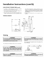
Venting
AWARNING
AWARNING
The vent pipe from the
water heater must be 3" diameter ]
PVC schedule40 pipe and must slope upward I/4 inch per|
linear foot.
To insureproperventingof this gas-firedwater heater,the correct vent pipe diameter must be utilized. Any additionsof
other gas appliances on vent with this water heater will
adversey affectthe operaton ofthe water heater.
]
All vent gases must be completely vented to the outdoors of the
structure (dwelling).
The combustion and ventilation air flow must not be obstructed.
AWARNING
[
The water heater with draft hood installedmust be propertyI
ventedto a chimneywhichterminatesoutdoors.Never oper-I
ate thewater heater unlessit isventedto the outdoorsand has
adequateair supplyto avoidrisksof improperoperation,explos onor asphyxation.
f
_IWARNING
Obstructedor deteHo_s
health Hskor asphyxiation.
Failureto haverequired clearancesbetweenwater heater
•,WARNING
and
combustbe materialw resut n a fire hazard.
may presenta serious
15
Installation
Instructions
(cont'd)
Venting (cont'd)
VENTING
FOR ALL
Be sure vent pipe is properlyconnectedto preventescape
AWARNING
of
dangerousfluegaseswhichcouldcausedeadlyasphyxiation.
SYSTEM
MODELS
EXAMPLE
INSTALLATIONS
The vent piping cannot under any circumstances be run downhill.
AWARNING
Chemical vapor corrosion of the flue and vent system may
occur if air for combustion contains certain chemical vapors.
Spray can propellants, cleaning solvents, refrigerator and air
conditioner refrigerants, swimn_ing pool chemicals, calcium
and sodium chloride, waxes, bleach, and processchemicals are
typical compounds which are potentially corrosive.
3" PVC SCHEDULE
40 VENT
PIPING
Supplied in the carton with the water heater are:
1. A 3" PVC Schedule 4045 ° vent cap with wire screen.
2. A 3" PVC Schedule 40-90 ° street ell; used to connect the
vent pipe to the water heater when the vent pipe is to be
turned horizontally directly off the blower.
The vent piping can be installed as follows:
1. No more than 3 elbows can be used.
3. A 5' section of 3" PVC Schedule 40 pipe (more may be
required and must be supplied locally).
4>
3" PVC SCHEDULE 40
90° ELBOW
MIN. RISE I/4"
PER FOOT
VENT CAP
WITH SCREEN
TOTAL VERTICAL AND
HORIZONTAL RUNS
CANNOT EXCEED 35'
I
1. The water
system.
heater
requires
its own
(separate)
venting
MAX, 3
2. 3" PVC, ABS or CPVC Schedule 40 piping and fittings are
acceptable materials for the vent system on all 40 gallon
models and 50 gallon 40,000 BTU/HR models.
3. It cannot
chimney.
be connected
4. It must terminate
to existing
vent
piping
MIN. RISE I/4"
PER FOOT
or
MAX
horizontally
20'
to the outdoors.
TOTAL VERTICAL AND
HORIZONTAL
RUNS
CANNOT
EXCEED 35'
MIN. RISE i/4"
PER FOOT
16
Installation
Instructions
VENTING SYSTEM EXAMPLE
FOR ALL MODELS (cont'd)
2. Horizontal
INSTALLATIONS
•
,
.
runs require
a mmtmum¼
i
-
(cont'd)
CEMENTING PVC, ABS OR CPVC PIPE AND FITTINGS
Read and observe all safety information printed on primer,
cleaner, and cement containers.
,
rtse
per foot.
DANGER
Primer, cleaner, and cements are extremely flammable.
They are harmful or fatal if swallowed. The vapors are
harmful. They may irritate eyes and skin and can be
absorbed through the skin.
13"MIN.
PRECAUTIONS
Always store primers, cleaner, and cements in cool, dry,
well ventilated places. Do not store them near heat,
sparks, or flames. Keep containers closed. Use them in
well ventilated areas. Wear impervious clothing while
handling. Do not smoke, eat, or drink while handling.
Wash thoroughly after handling and before eating. Wear
eye protection when handling. If swallowed, drink water,
do not induce vomiting, and call a physician or poison
control center immediately. If inhaled, get fresh air and
seek medical attention if ill feelings persist. In case of
eye and skin contact, immediately flush with plenty of
water for 15 minutes and seek medical attention if irritation persists. KEEP OUT OR REACH OF CHILDREN.
MIN. RISE7,"
PERFOOT
I I" MIN.
I
3. A vertical run can be no more than 20'.
4. The total vertical and horizontal
run cannot exceed 35'.
ONE ELBOW
All primers, cleaners, and cements must meet all local codes and
applicable
standards
of the American
Society For Testing
Materials Standards•
MIN. RISE%"
PERFOOT
Before using primers, cleaners, and cements, stir or shake, makin sure contents are liquid. Do not use if found to be lumpy or
jelly-like.
MAX. 20'
1. Cut pipe ends squarely removing
TOTAL VERTICAL AND
HORIZONTAL RUNS
CANNOT EXCEED 35'
all burrs and dirt.
2. Dry fit pipe and fittings to be connected
for proper fit.
3. Clean pipe and fitting with a primer/cleaner.
4. Apply a thin coat of cement
inside.
to fitting,
avoiding
puddling
5. Apply a liberal coat of cement to pipe leaving no voids.
6. QUICKLY
assemble parts while cement
too long, re-coat pipes.
7. Push pire completely
until _t oottoms.
MAX. 20'
I
HIN. RISE ¼"
PER FOOT
I
is flui!! If you wait
into socket of fitting, turning
as it goes
8. Hold pipe and fitting together for 30 seconds. Then carefully
clean off excess with a cloth. Allow connections a sufficient
time to cure before disturbing.
MIN. RISE ¼"
PER FOOT
9. Remember
supported.
that vent pipes must be adequately
APPROXIMATE
OINTS
TOTAL VERTICAL AND
HORIZONTAL
RUNS
CANNOT
EXCEED 35'
SETTING
TIME
MOVEMENT
90°F to 150°F
50°F to 90°F
0°F to 50°F
17
OF JOINT
_hr.
1 hr.
1_ hr.
and securely
FOR 2V_,"TO 4" PIPE
COMPLETE
SET
8 hrs.
15 hrs.
18 hrs.
Installation
Instructions
(cont'd)
Venting (cont'd)
CUTTING
OPENING
THROUGH
AN
WALL AND COLLAR INSTALLATION
OUTSIDE
CONNECTING
BLOWER
After reading the manual and you have determined the location
of the opening in the wall, (using the drawing below), cut a 3_"
hole through an exterior wall.
PVC, ABS OR CPVC PIPE VENT TO
1. The manufacturer has supplied a 3" PVC Schedule 40 street
elbow for connection to the water heater when turning immediately horizontally off the blower. Place the elbow in the
required direction on the blower and using 3 sheet metal
screws, attach the elbow.
NOTE: When determining location of the opening in the
outside wall allow for the 'A" rise per foot that has taken
place in the horizontal run.
__ of Flue
I
I' MIN.
€
MIN. RISE¼"
j
k
- -i:ET _q .
I
I
40 GAL.- 60"
50 GAL.- 59¼"
2. If there is to be a vertical run of vent from the blower, the 3"
PVC or ABS pipe must be attached to the blower using 3 sheet
metal screws. Additionally, you must sea! all joints using a suitable silicone sealer such as GE RTV-103 or equivalent.
../"
/
J
The 3" PVC, ABS or CPVC Schedule 40 vent pipe can be run
from the water heater through the wall or from the wall to the
water heater, whichever is most convenient. The vent pipe must
extend a minimum of IV_,"through the exterior wall. Extending
the vent cap as far as possible from the surface of the exterior
wall will help minimize discoloration of the wall in this area
which may be caused by the flue gases. Note that the inside collar must be slipped over the vent piping before locating the pipe
through the wall. Before securing the inside and outside collars
to the wall, use a silicone sealer between pipe and opening to
insure a water and air tight seal.
INSTALLATION
CPVC PIPE
SHOWING
/
USE OF PVC, ABS OR
/EXTERIOR
WALL
SEALER
SILICONE
_
1 'k" MIN.EXTENSION
THROUGH
EXTERIOR
WALL
i,..
SCREW
SCREW
SCREW
/
SEATER
/
/
VENT CAp MUST
POSITIONED
DOWNWARD
BE
18
Installation
Instructions
(cont'd)
Gas Piping
AWARNING
AWARNING
Make sure the gas supplied is the same type listed on the
model rating plate. The inlet gaspressuremust not exceed
10.5in. water column(2.6kPa) for natural gasor 13 in,water
column (3.2kPa) for propane(LR) gas. The minimum inlet
gaspressurelistedon the model rating plate is for the purposeof inputadjustment.
I
Use pipe joint compound or teflon tape marked as being
resistant to the action of petroleum [Propane (L.R)] gases.
SEDIMENT
TRAP
A sediment trap shall be installed as close to the inlet of the
water heater as practical at the time of water heater installation.
The sediment trap shall be either a tee fitting with a capped nippie in the bottom outlet or other device recognized as an effective sediment trap. Ifa tee fitting is used, it shall be installed in
conformance with one of the methods of installation shown
below.
AWARNING
If the gas control valve is subjected to pressures exceeding ½ [
pound per square inch (3.5kPa), the damage to the gas contro valve could result in a fire or explosion from eak ng gas.
Connecting the gas piping to the gas control valve of the water
heater can be accomplished by either of the two methods shown.
AWARNING
If the main gas line shutoff serving all gas appliances is used, I
also turn "off" the gas at each appliance. Leave all gas appli-
GAS PIPING WITH
FLEXIBLE CONNECTOR
ances shut off until the water heater installation scomp ete.
A gas line of sufficient size must be run to the water heater.
Consult the latest edition of National Fuel Gas Code ANSI
Z223.1, also referred to as NFPA 54 and the gas company concerning pipe size.
SHUT OFF
MANUAL
[j_(
AS SUPPLY PIPING
VALVE
FLEXIBLE GAS CONNECTOR
LABELED AS COMPLYING
WITH ANSI STANDARDS
There must be:
• A readily accessible manual shut off valve in the gas supply line
serving the water heater, and
• A drip leg (sediment trap) ahead of the gas control valve to help
prevent dirt and foreign materials from entering the gas control
LOOP
UNION
(Optional)
GAS
CONTROL
VALVE
Valve,
GROUND JOIN_
3" MIN.
• A flexible gas connector or a ground joint union between the
shutoffvalve and control valve to permit servicing of the unit.
Be sure to check all the gas piping for leaks before lighting the
water heater. Use a soapy water solution, not a match or open
flame. Rinse offsoapy solution and wipe dry.
GAS PIPING WITH ALL BLACK
PIPE TO GAS CONTROL
Standard Models are for installation up to 3,300 feet above sea
level.
High Altitude Models are for installation from 3,300 to 5,500
feet above sea level.
If a standard model is installed above 3,300 feet or a high altitude
model is installed above 5,500 feet, the input rating must be
reduced at the rate of 4 percent for each 1,000 feet above sea level.
Contact your local Sears Service Center or gas utility for further
information.
MANUAL
SHUT OFF _CAS
IRON
SUPPLY PIPING
VALVE
BLACK PIPE
GROUND
UNION
GAS
CONTROL
VALVE
AWARNING
(Sediment
trap)
I The appliance and its gas connection must be leak tested
CAP
[ before placing the appllance in operation.
=t WARNING
AWARNING
Contaminants in the gas lines may cause improper operation
of the gas control valve that may result in fire or explosion.
Before attaching the gas line be sure that all gas pipe is clean
on the inside. To trap any dirt or foreign material in the gas
supply line, a drip leg (sometimes called a sediment trap)
must be incorporated in the piping. The drip leg must be
readily accessible. Install in accordance with the "Gas Piping"
section. Refer to the latest edition of the National Fuel Gas
Code, ANSI Z223. I, also referred to as NFPA 54.
• The appliance and its individual shutoff valve must be disconnected from the gassupply piping system during any pressure
testing of the gas system at test pressures in excess of I/2
pound per square inch (3.5kPa).
• The appliance must be isolated from the gas supply piping system by closing its individual manual shutoff valve during any
pressure testing of the gas supply piping system at test pressuresequal or lessthan I/2 pound per square inch (3.5kPa).
19
Installation
Instructions
Installation
Checklist
BEFORE LIGHTING
THE PILOT:
•
(cont'd)
VENT PIPE TO
OUTDOORS
Check the gas lines for leaks.
a. Use a soapy water solution. DO NOT test for gas leaks
usinga match or open flame.
b. Brush the soapy water solution on all gas pipes, joints and
fittings.
c. Check for bubbling soap. This means you have a leak.
Turn "OFF" gas and make the necessary repairs.
d. Recheck for leaks.
e. Rinse off soapy solution and wipe dry.
COLD
SHUTOFF
VALVE
• Is the new temperature-pressurerelief valve properly installed
and piped to an adequate drain? See "Temperature-Pressure
Relief Valve" section.
TEMPERATUREPRESSURERELIEF
VALVE
• Are the cold and hot water lines connected to the water
heater correctly? See "Water Piping" instructions in the
"Installing the New Water Heater" section.
•
HOT
Is the water heater completely filled with water? See "Filling"
instructions
in the "Installing the New Water Heater" section.
DISCHARGE PIPE
(Do not cap or plug)
• Will a water leak damage anything? See the "Locating the
New Water Heater" secnon.
Is there proper clearance between the water heater and anything that might catch fire? See the "Locating the New water
Heater" section.
GASSUPPLY
Do you have adequate ventilation so that the water heater
will operate properly? See "Combustion
Air and Ventilation"
in the "Locat'ng the New Water Heater' section.
SHUTOFFVALVE
Is the draft hood vent ppi ingp roperly secured_.See "Venting"
instructions in the "Installing the New Water Heater" section.
Is there proper clearance between the vent pipe and anything
that might catch on fire? See "Venting" instructions in the
"Installing the New Water Heater" secnon.
DRIP !
(Sediment trap)
PIPECAF
Is the vent pipe properly sloped and does the vent terminate
outdoors? See "Venting" instructions
in the "Installing the
New Water Heater" section.
"AUTONATIC STORAGE WATER
"NnTL"
RRATL;'R" SUITABLE FOR WATER
(POTABLB) _TZ.G
O.LY
t,t,,_)}
Do you need to call your gas company to check the gas pipe
and its hookup?
_o
ANSi1
I
Id4_lk_
I
Ph'_O_TATIC
P_i_
OAS
w_c
MODEL
20
f
10
RATING
_44JI_E
lq W C
w_c_
PLATE
wc
Operating
Instructions
This water heater is equipped with an electrically operated venting system and a standing pilot. For the burner to come on, the
water heater thermostat must call for heat. Then the system will
begin sequencing,
each section proving itself before gas is
allowed to flow to the burner.
BEFORE
THE
WATER
HEATER
WILL
BLOWER MOTOR
OPERATE:
VENTING
MANUAL
RESET SWITCH
1. The control system must be connected
to a 110/120 volt
power supply. The control system has an overall rating of 2
amps. The water heater must be securely and adequately
grounded in accordance with local codes and with the latest
edition of the National Electrical Code ANSI/NFPA
70.
DRAFT HOOD
2. The ON/OFF toggle switch, located on the control box
above the thermostat must be in the "ON" position for the
electrical control system to operate allowing the gas portion
to operate (ignite burner).
3. The pilot must be lit. See Lighting instructions on page 23
of this manual or located adjacent to the thermostat on the
water heater.
ON/OFF SWITCH
AIR PRESSURE
SWITCH
4. The gas control knob located on the thermostat must be
turned to the "ON" position for the gas to be able to flow.
5. The venting manual reset switch must be in the closed position. See "Venting Manual Reset Switch" in the "For Your
Information Section".
LIGH%_
6. There is a non-resettable hi-limit switch in the thermostat,
which must be good (closed) for the thermostat to be operated. See "High Temperature Shut Off System" in the "For
Your Information Section".
GAS CONTROL
OPERATION
KNOB
When the thermostat calls for heat, gas is allowed to flow to a
(Normally open) pressure switch closing it. An electrical circuit
is then made to the blower, turning it on. The indicator light
located on the control box will come on. When the blower has
achieved sufficient venting, the air pressure switch will close and
the indicator light will go off. A 120 volt circuit will be completed through the venting manual reset switch and on to the
120 volt gas valve located just below the thermostat. The 120
voltgas valve will open allowing gas to flow to the burner. The
standing pilot will establish a main burner flame.
GAS THERMOSTAT
BURNER
120V GAS VALVE
21
Operating
Instructions
Lighting
_,WARNING
BEFORE LIGHTING
[PROPANE
(L.P.) GAS WATER
HEATERS]: Propane (L.R) gas is heavier than air. Should there
be a leak in the system, the gas will settle near the ground.
Basements, crawl spaces, skirted areas under mobile homes
(even when ventilated), closets and areas below ground level will
i serve as pockets for the accumulation of this gas. Before
attempting to light or relight the water heater_ pilot or turning
on a nearby electrical light switch, be absolutely sure there is no
accumulated gas in the area. Search for odor of gas by sniffing at
ground level in the vicinity of the appliance. If odor is detected,
follow steps indicated at "For Your Safety" on the cover page of
this manual then leave the premises.
I Figure
9 I
IFigure
101
Figure
II1
Lighting and operating instructions are located on front of the
water heater, above or to one side of'the gas control valve.
_,WARNING
AN ODORANT IS ADDED TO THE GAS USED
BY THIS WATER HEATER.
FOR YOUR SAFETY
IF YOU SHELL GAS:
Do not try to light any appliance.
Do not touch any electrical switch; do not use any phone in
your building.
Immediately call your gas supplier from a neighbor's phone.
Follow the gas supplier's instructions.
If you cannot reach your gas supplier, call the fire department.
_,WARNING
DO NOT force the gas control knob. Use only your hand to
push it down to light the pilot, or to turn it to "ON", "OFF"
or "PILOT". Never use a tool such as a lever, wrench or pliers. Do not hit or damage the knob. A damaged knob may
result in an explosion and serious injury. If you have problem
turning the knob, call the gas supplier immediately.
Figure
22
121
INNER
DOOR
OUTER
DOOR
Operating
Lighting
Instructions
label
on the water
FOR YOUR
heater
SAFETY
(cont'd)
as it appears
READ
above
BEFORE
the thermostat
LIGHTING
I
WARNING
If you do not follow these instructions exactly, a fire or explosion
may result causing property damage, personal injury or loss of life.
A. This appliancehas a pilot which must be lightedby
hand.Whenlightingthe pilot,followtheseinstructions
exactly.
B. BEFORELIGHTINGsmellall aroundtheappliancearea
for gas. Be sure to smell next to the floor because
somegasis heavierthanair and willsettleon the floor.
WHATTODOIF YOUSMELLGAS
• Do nottry to lightanyappliance.
• Do not touch any electric switch; do not use any
phonein yourbuilding.
• Immediatelycall your gassupplierfrom a neighbor's
phone.Followthe gaseupplier'sinstructions.
LIGHTING
• If you cannotreach your gas supplier,call the fire
department.
C. Useonlyyour handto pushin or turn thegas control
knob.Never usetools. If the knobwill not pushin or
turnby hand,don'ttry to repairit, call a qualifiedservice technician.Forceor attemptedrepair may result
in a fire or explosion.
D. Do not use this applianceif any part has been under
water.Immediatelycall a qualifiedservicetechnician
to inspecttheapplianceandto replaceanypart ofthe
controlsystemand any gas controlwhich has been
underwater.
INSTRUCTIONS
1. STOP!Readthe safetyinformationaboveonthis label.
2. TurnON/OFFswitchon controlboxto "OFF".
3. Remove outer door covering gas thermostat and
burnerassembly.(Figure12,Page22)
4. Set the thermostat to lowest setting
by turning the water temperaturedial
clockwise,(,_)
to its lowesttemperature setting (with arrow on dial) as
shown. DO NOT FORCE, (Figure 9,
Page22)
5. Turn gas controlknobclockwiseV
to "OFF" position. Knob cannot be turned from "PILOT" to "OFF"
unlessknobis depressedslightly.DO NOT FORCE.
6. Wait five (5) minutesto clear out any gas. If you then
smell gas, STOP!Follow"B" in the safety information
above on this label. If you don't smell gas, go to the
nextstep.
7. Remove(or open) inner door located below the gas
controlunit.
8. Findpilot-followmetaltubefrom gascontrol.The pilot
is locatedon themanifoldTHERMOCOUPLE
PILOT
BURNER
insidethe combustion
:n
J
chamber.
' _9,'-t
J '_:=
9. If you don't smell gas, turn knob on gas control
counter-clockwise
_@
Page22)
10.Push in control knob all the way and hold down.
Immediately light the pilot with a match. Continue
to hold control knob in for about one (1) minute
after the pilot is lit. Release knob and it will pop
back up. Pilot should remain lit. If it goes out,
repeatsteps 5 through 10.
• If knob does not pop up when released, stop
and immediatelycall your service technicianor
gas supplier.
• If the pilot will not stay lit after several tries,
depress and turn the gas control knob clockwise _
1 to "OFF" andcall yourservicetechnicianor gassupplier.(Figure9, Page22)
11.Replaceinnerdoor.(Figure12,Page22)
12.At arms lengthaway,turn gas controlknobcounterA
clockwise_
to the full "ON" position.WARNING
Do not use gas control knob to regulate gas
flow, (Figure11,Page22)
13. At arms length away,set the thermostatto desired
setting.The mark (T) HOT indicativeof approximate
120°Fis preferredstartingpoint.Somelocallawsmay
require a lower starting point. If hotter water is
desired,see instructionmanualand "warning" below.
14.Replacethe outerdoor.(Figure12,Page22)
15. TurnON/OFFswitchon controlboxto "ON".
to "PILOT"position.(Figure9,
Hotter water increasesthe risk of scald injury.WARNING
Beforechanging temperature setting see instructionmanual.
TO TURN
OFF GAS TO APPLIANCE
1. Turn ON/OFF switch on control box to "OFF".
2. Remove outer door covering gas thermostat and
burnerassembly.(Figure 12, Page 22)
,_j
3. Set the thermostat to lowest setting
by turning the water temperature
dial clockwise (F_'_,) to its lowest
temperaturesetting (with arrowon dial)
asshown. DO NOT FORCE, _
4. Turngascontrolknobclockwise"_" "to "OFF" position. Knobcannotbe turned from "PILOT" to "OFF"
unlessknobis depressedslightly.DO NOT FORCE,
(Figureg, Page22)
5. Replaceouter door.(Figure12, Page22)
23
Operating
Temperature
Instructions
(cont'd)
Regulation
Due to the nature of the typical gas water heater, the water tem_oerature in certain situations
may vary up to 30°F higher or
wet at the point of use such as, bathtubs, showers, sink, etc.
Turn the water temperature dial clockwise (f'-_)
to decrease
the temperature,
or counterclockwise
(_-"'-_)
to increase the
temperature.
This means that when the temperature adjustment dial is set at
the mark approximating 120° F, the actual water temperature at
any hot water tap could be as high as 150°F or as low as 90°F.
Any water heater's intended purpose is to heat water. Hot water
is needed for cleaning (bodies, dishes, clothing). Hot water will
present a scald hazard. Depending on the time element, and the
people involved (normaladults,
children,
toddlers,
elderly,
infirm, etc.) scalding may occur at different temperatures.
_,WARNING
HOTTER WATER CAN SCALD: Water heaters are intended to
produce hot water Water heated to a temperature which will
satisfyclothes washing,dish washing,and other sanitizing needs
can scald and permanently injure you upon contact. Some people are more likely to be permanently injured by hot water than
others. These include the elderly, children,the infirm, or physically/mentally handicapped.If anyone usinghot water in your home
Ets into one of these groups or if there is a local code or state law
requiring a certain temperature water at the hot water tap, then
€oumust take special precautions.In addition to using the lowest
3ossibletemperature setting that satisfies your hot water needs,
means such as a mixing valve, shouldbe usedat the hot water
taps used by these people or at the water heater, Mixing valves
are availableat plumbing supplyor hardware stores.Follow manufacturers instructions for installation of the valves. Before
changing the factory setting on the thermostat, read the
"Temperature Regulation" section in this manual.
• HOT-Is
a thermostat
setting of approximately
1200[;,
which will supply hot water at the most economical temperatures.
The temperature
ad ustment
kno
.
,
b can be turned lower than - HOT . lfdeszred.
A- Is a thermostat
setting of approximately
130°E
B
Is a thermostat
setting of approximately
140°E
Co- ls a thermostat
setting of approximately
150°E
VERY HOT-
Is a thermostat setting of 160°E It is recommended that the dial be set lower whenever possible.
NOTE:
Water temperature
mended by most dishwasher
AWARNING
Never allow smallchildrento usea hot water tap, or to draw
their own bath water, Never leavea childor handicappedpersonunattendedin a bathtub or shower
range of 120°-140°F
manufacturers.
recom-
_,WARNING
Shouldoverheating occuror the gassupplyfail to shut off,
turn "OFF" the manual gascontrolvalveto the appliance.
The thernmstat
of this water heater has been factory set at its
lowest position, to reduce the risk of scald injury. It is adjustable
and must be reset to the desired temperature setting. The mark
(•) HOT indicative of approximately
120°F is the preferred
startinl_ point. Some states have a requirement
for a lower setting. If you need hotter water, follow directions for temperature
adjustment, but beware of the warnings in this section.
24
Service
and Adjustment
Tank (Sediment)
Burner
Cleaning
Sediment build-up on the tank bottom may create varying amounts of
noise, and if left in the tank will cause premature tank failure. In some
water areas, you may not be able to drain all sediment deposits by
simply draining the tank. in these cases Mag Erad (part no. 23600)
can be used to help remove the sediment deposits. This may be
ordered from the Sears Service Center. For ordering, refer to the
"Repair Parts" section.
Venting
System
Inspection
AWARNING
Do not use this appliance if any part of it has been under water.
Immediately call a Sears Service Technician to inspect the
appliance and to replace the gas control or any part of the
burner system which hasbeen under water.
At least once a ),ear a visual inspection should be made of the
main burner and pilot burner. The drawing is for your reference.
Inspection
You should check for sooting which is not normal and will
impair proper combustion.
At least once a year a visual inst)ection should be made of the
venting system. You should look for:
Obstructions
which could cause iioproper venting. The combustion and ventilation air flow nmst not be obstructed.
Damage or deterioration which could cause improper venting
or leakage of combustion products.
Rusted flakes around top of water heater.
AWARNING
Chemical vapor corrosion of the flue and vent system may
occur if air for combustion contains certain chemical vapors.
Spray can propellants, cleaning solvents, refrigerator and air
conditioner refrigerants, swimming pool chemicals, calcium
and sodium chloride, waxes, bleach, and process chemicals are
typical compounds which are potentially corrosive.
AWARNING
AWARNING
J
Soot build-up indicates a problem that requires correction J
before further use. Turn "off" gas to water heater and leave J
"off" until repairs are made, because failure to correct the J
cause of the sooting can result in a fire or explosion causing
death, serious bod y njury, or property damage.
I
Obstructed or deteriorated vent systems may present a serious
health risk or asphyxiation.
Burner Cleaning
I
In the event
instructions:
AWARNING
Be sure the vent piping is properly connected to prevent
escape of dangerous flue gasses which could cause deadly
Oiling
needs
cleaning,
use the following
NOTE: The knob cannot he turned from "PILOT" to "OFF"
unless knob is depressed slightly. DO NOT FORCE.
J
If after inspection of the vent system you found sooting or I
deterioration, something is wrong. Call the local gas utility to
correct the problem and clean or replace the flue and venting
before resum ng operat on of the water heater.
burner
If inspection of the burner shows that cleaning is required, turn
the gas control knob clockwise (f"-"_)
to the "OFF" position,
depressing slightly.
asphyxiation.
AWARNING
your
Loose deposits on or around the burner can be removed by carefully using the hose of a vacuum cleaner inserted through the
access door of the water hearer. If the burner needs to be removed
for additional cleaning, call the Sears Service ('.enter to remove
and clean the burner and correct the problem that required the
burner to be cleaned.
]
Instructions
Oil motor every 12 months with 6 drops of SAE 20 cnotor oil
(Fasco motor only).
25
Service
and Adjustment
L.R Gas Control Valve & Burner
Assembly Replacement
Information
(cont'd)
Draining
The water heater should be drained if being shut down during
freezing temperatures.
Also periodic draining and cleaning of
sediment from the tank may be necessary.
Turn the gas control knob to the "OFF" position.
CLOSE the cold water inlet valve to the water heater.
OPEN a nearby hot water faucet and leave open to allow for
draining.
Connect a hose to the drain valve and terminate to an adequate drain.
OPEN the water heater drain valve to allow for tank draining.
NOTE: If the water heater is going to be shut down and
drained for an extended period, the drain valve should be
left open with hose connected allowing water to terminate
to an adequate drain.
Close the cirain valve.
Follow instructions in the "Filling The Water Heater" section.
Follow the lighting instructions in the "Lighting" section to
restart the water heater.
AWARNING
PROPANE (L.R) GAS CONTROL VALVE AN BURNEI
ASSEMBLYREPLACEMENT INFORMATION.
For Propane (L.R) Gas Models Only:
Your water heater is equipped with a Propane (LR) gas con
trol valve and a main burner assembly with left hand threads
for the following fittings and their connections.
The connection between the manifold and the gas
control valve (A to B) are left hand threads.
The connection between the main burner orifice
and the manifold (C to D) are left hand threads.
For ordering these replacement
parts, please refer to
the "Repair Parts" section of this manual.
Temperature-Pressure
Valve Operation
Relief
The temperature-pressure rehefvalve must be manually operated
at least once a year.
TEMPERATURE-PRESSURE
RELIEF VALVE
A
DISCHARGE
PIPE
Failure to install and maintain a new properly listed temperature-pressure relief valve will release the manufacturer from any
claim which might result from excessivetemperature or pressure.
AWARNING
If the temperature-pressure relief valve on the appliance
weepsor dischargesperiodically,this may be due to thermal
expansion. Your water heater may have a check valve
installed in the water line or a water meter with a check
valve. Consultthe SearsServiceCenter for further information. Do not plugthe temperature-pressurerelief valve.
AWARNING
When checking the temperature-pressure relief valve operation, make sure that (I) no one is in front of or around the
outlet of the temperature-pressure relief valve discharge line,
and (2) that the water manually discharged will not cause any
property damage because the water may be extremely hot.
If after manually operating the valve, it fails to completely
reset and continues to release water, immediately close the
cold water inlet to the water heater, follow the draining
instructions, and replace the temperature-pressure
relief
valve with a new one.
26
Service
and Adjustment
Drain Valve Washer
Replacement
NOTE: For replacement, use a '_2" x "/_" x Y_"thick washer
available at your nearest hardware store. For ordering replacement washers, refer to the "Repair Parts" section.
Turn "OFF" gas supply to water heater.
Follow "Draining" instructions.
Turning counter clockwise, remove the hex cap below the
screw handle.
Remove the washer and put the new one in place.
Screw the handle and cap assembly back into the drain valve
and retighten using a wrench. DO NOT OVER TIGHTEN.
Follow instructions
in the "Filling The Water Heater"
section.
Check for leaks.
Follow the lighting instructions in the "Lighting" section to
restart the water heater.
_
HANDLEAND
CAP ASSEMBLY
WASHER
Housekeeping
Vacuum around base of water heater for dust, dirt, and lint on a
regular basis.
Combustible materials such as clothing, cleaning materials, or
flammable liquids, etc. must not be placed against or adjacent to
the water heater.
To insure sufficient ventilation and combustion air supply, proper clearances from the water heater must be maintained at all
times.
Service
Before calling for repair service, read the Start Up Conditions
and Operational
Conditions
found in the Troubleshooting
Guide of this manual.
If a condition persists or you are uncertain about the operation
of the water heater, let a qualified person check it out.
Contact SEARS Repair Services
(1-800-469-4663)
at 1-800-4-MY-HOME
27
(cont'd)
Troubleshooting
Guide
Start Up Conditions
THERMAL
EXPANSION
HOT
COLD WATERHEATER
:=I1£ COLDWATER
Water supply systems may, because of such events as high line
pressure, frequent cut-offs, the effects of water hammer among
others, have installed devices such as pressure reducing valves,
check valves, back flow preventers, etc...to control these types of
_roblems. When these devices are not equipped with an internal
y-pass, and no other measures are taken, the devices cause the
water system to be closed. As water is heated, it expands (thermal expansion) and closed systems do not allow for the expansion of heated water.
"
The water within the water heater tank expands as it is heated and
increases the pressure of the water system. If the relieving point of
the water heater's temperature-pressure
relief valve is reached, the
valve will relieve the excesspressure.
The temperature-pressure
relief valve is not intendedfor
the constant relief of thermal
expansion.
This is an unacceptable condition and must be corrected.
PRESSU(R gGAUG
WATER
SHUTOFF
RECOMMENDED INSTALLATION
(VERTICAL MOUNTING)
_,m====,m==_
It is recommended that any devices installed which could create a
closed system have a by-pass and/or the system have an expansion tank to relieve the pressure built by thermal expansion.
Thermal expansion
tanks are available from Sears stores and
through the Sears Service Centers. Contact the local plumbing
inspector, water supplier and/or the Sears Service Center for
assistance in controlling these situations.
WATER HEATER
COLD WATER
INLET FITTING
FLOOR, CEILING
JOIST, ETC,
HOT
Thermal
Model
Number
STRAPPING
Expansion Tank Specifications
Tank C_lpacity
In Gallons
Dimensions in Inches
D ameter . Length
2
8 inches
127, inches
Vi' Male
i531331050
5
llinches
14_inches
W'Male
4
Tank
Sizing
O)
PRESSURE
REDUCING INLETCOLD
VALVEWITH
WATER
BY-PASS SHUTOFF
i Pipe Fitting
On Tank
153.331020
Expansion
(3)
PRESSURE
REDUCING
VALVEWITH
BY-PASS
bINLET FITTING
(i)
EXPANSION
(21
Chart
PRESSURE GAUGE
Inlet*
Water Heater Capacity
(Gallons)
ALTERNATE RECOMMENDED
INSTALLATION
(HORIZONTAL MOUNTING)
Water
Expansion
Tank
Capacity
Needed
Pressure
40psi
50psi
60psi
70psi
80psi
30
!
2
2
2!2
2
2
40
2
2
2
5
50
2
2
5
5
5
66
5
5
5
5
5
82
5
5
5
5
5
STRANGE
SOUNDS
Possible noises due to expansion and contraction of some metal
parts during periods of heat-up and cool-down do not represent
harmful or dangerous conditions.
*Highest recorded inlet water pressure in a 24 hour period or
regulated waterpressure.
Condensation causes sizzling and po 3ping with the burner area
during heating and cooling periods and should be considered
normal. See "(]ondensation" section.
NOTE: Expansion tanks are pre-charged with a 40 psi air
charge• If the inlet water pressure is higher than 40 psi, the
expansion tank's air pressure must be adjusted to match that
pressure, but must not be higher than 80 psi.
28
Troubleshooting
Guide
(cont'd)
CONDENSATION
SMOKE/ODOR
Whenever the water heater is filled with cold water, a certain
amount of condensation will form while rile burner is on. A
water heater may appear to be leaking when in Fact die water is
condensation. This usually happens when:
• When a new water heater is filled with cold water for the
first time.
• When gas burns and water vapor isproduced in water
heaters, particularly high ei_]ciency models where flue temperatures are lower.
• When you use large amounts of hot water in a short time
and the refill water is very cold.
It is not unconnnon to experience a small amount of smoke and
odor during the initial start-up. This is due to burning off of oil
from metal parts, and will disappear in a short while.
Operational
SMELLY
Conditions
WATER
In each glass[ined water heater there is installed at [east one
anode rod (see parts section) for corrosion protection of the
tank. Certain water conditions will cause a reaction between this
rod and the water. The most common complaint associated with
the anode rod is one of a "rotten egg smell". This odor is derived
from hydrogen sulfide gas dissolved in the water. The smell is
the result of four factors which must all be present for the odor
to develop:
Moisture from the products of combustion condense on the
cooler tank surfaces and form drops of water which may fall
onto the burner or other hot surfaces to produce a "sizzling" or
"frying" noise.
Excessive condensation can cause pilot outage due to water running down the flue tube onto the main burner and putting out
the pilot.
a. a concentration
of sulfate in the supply water.
b. little or no dissolved oxygen in the water.
c. a sulfate reducing bacteria within the water heater. (This
harmless bacteria is non-toxic to humans.)
d. an excess of active hydrogen in the tank. This is caused by
the corrosion protective action of the anode.
Because of the suddenness and amount of water, condensation
water may be diagnosed as a "tank leak". After the water in the
tank warms up (about 1-2 hours), the condition should disappear.
Do not assume the water heater is leaking until there has been
enough time for the water in the tank to warm up.
Smelly water may be eliminated or reduced in some water heater
models by replacing the anode(s) with one of less active material,
and then chlorinating the water heater tank and all hot water
lines. Contact Sears Service for further information concerning
an Anode Replacement Kit #9001453 and this Chlorination
Treatment.
An undersized water heater will cause more condensation. The
water heater must be sizedproperly to meet the family's demands
for hot water including dishwashers, washing machines and
shower heads.
Excessive condensation
may be noticed during the winter and
early spring months when incoming water temperatures
are at
their lowest.
If the smelly water persists after the anode replacement and chlorination treatment, we can only suggest that continuous chlorination and filtering conditioning equipment be considered to
eliminate the water problem.
Good venting is essential for a gas fired water heater to operate
properly as well as to carry away products of combustion
and
water vapor,
Do not remove the anode leaving the tank unprotected. By
doing so, all warranty on the water heater tank is voided.
AWARNING
HOTTER WATERCAN SCALD:Water heatersareintendedto
_roducehot water. Water heatedto a temperaturewhichwill
satisfyclotheswashing,dishwashing,and other sanitizing needs
can scaldand permanentlyinjureyou uponcontact.Somepeo>leare more likelyto be permanentlyinjuredbyhot waterthan
others.Theseincludethe elderly,children,the infirm,or physically/mentallyhandicapped.
If anyoneusinghot water in yourhome
fitsintoone ofthese groupsor if there isa localcodeor statelaw
requiring a certaintemperature waterat the hot water tap, then
€oumusttake specialpRcautions.In additionto usingthe lowest
)ossibletemperaturesettingthat satisfies
yourhot water needs,
i meanssuchasa mixingvalve,shouldbe usedat the hot water
tapsusedby these peopleor at the water heater.Mixingvalves
areavailableat plumbingsupplyor hardwarestores.Followmanufacturers instructionsfor installationof the valves. Before
changingthe factory setting on the thermostat, read the
"Temperature Regulation"sectionin this manual.
29
Troubleshooting
Operational
"AIR"
Conditions
IN HOT WATER
Guide
(cont'd)
FAUCETS
WATER
HYDROGEN GAS: Hydrogen gas can be produced in a hot
water system that has not been used for a long period of time
(generally two weeks or more). Hydrogen gas is extremely
flammable and explosive. To prevent the possibility of injury
under these conditions, we recommend the hot water faucet
be opened for several minutes at the kitchen sink before any
electrical applianceswhich are connected to the hot water system are used (such as a dishwasher or washing machine). If
hydrogen gas is present, there will probably be an unusual
sound similar to air escaping through the pipe as the hot water
faucet is opened. There must be no smoking or open flame
near the faucet at the time it isopen.
TEMPERATURE
SHUT
AWARNING
Due to the nature of the typical gas water heater, the
water temperature
in certain situations may be hotter
than the thermostat setting.
Short, frequent draws of hot water - especially with very
cold incoming water - can shock the thermostat into brief
operation resulting in hotter and hotter layers of water
closer to the top of the tank.
Changes in hot water usage patterns or raising the temperature differential between the cut-on of the thermostat and the cold water temperature will usually eliminate
the problem.
This water heater is equipped with an automatic gas shut off system. The high temperature shut off is built into the gas control
valve. This system shuts off the gas supply to the water heater
burners when high water temperatures are present. It is nonresettable. If the high temperature shut off activates, the gas control valve must be replaced. If this were to occur, turn "OFF" the
entire gas supply to the water heater. Contact the Sears Service
Center.
I
Should overheating occur or the gas supply fail to shut off,
turn "OFF"
the manual gas control valve to the app ance.
NOT ENOUGH
•
•
•
°.
•
•
•
•
•
HOT
2. If lower temperature settings will not lower the water temperature, call the Sears Service Center.
OFF SYSTEM
AWARNING
IS TOO
1. The temperature adjustment dial may be set too high. See the
"Temperature Adjustment" section.
NOTE: A period of time is necessary after an adjustment has
been made for the water temperature to reach the new temperature setting.
AWARNING
HIGH
(cont'd)
OR NO HOT WATER
Check the manual gas shut offvalve to be sure it is open.
Check the pilot flame. It may have gone out. All models have
an opening behind the outer door for viewing the pilot.
If the pilot is not lit, follow the "Lighting" instructions in this
manual or located above the gas control valve on the water
heater to rdight the pilot. If the water was extremely hot and is
now cold, the high limit safety temperature shut off may have
put out the burner and pilot. If the high temperature shut off
activates, the gas controlvalve
must be replaced. Contact the
Sears Service Center.
The gas control knob must be turned to the "ON" position.
The temperature adjustment dial may be set too low. See the
"Temperature Regulation" section.
The gas company can check the gas input to see if it is correct.
An underflred water heater will not heat water as quickly.
Look for leaking or open hot water }aucets. Make sure all are
closed.
The cold water inlet temperature may be colder during the winter months. It will take longer to heat the water and seem like
less hot water,
If you cannot find what is wrong, call the Sears Service Center.
3O
Troubleshooting
Guide
(cont'd)
Leakage Checkpoints
Use this guide to check a "Leaking" water heater. Many suspected "Leakers" are not leaking tanks. Often the source of the water
can be found and corrected.
• , CAUTION
J
Read this manual first. Then before checking the water J
heater make sure the gas supply has been turned
"OFF", and never turn the gas "ON"
before the tank is
if you are not thoroughly familiar with your local gas codes your
water heater, and safety practices, contact the Sears Service
Center to check the water heater.
comp ere y fu
of water.
• , CAUTION
J
Never use this water heater unless it is completely filled J
with water. To prevent damage to the tank, the tank J
must be filled with water. Water must flow from the hot I
water faucet before turning "ON"
gas to the water
heater.
O
Water at the draft hood is water vapor which has condensed out of the combustion products. This is caused by a
problem in the vent. Contact the Sears Service Center.
O
*Condensation may be seen on pipes in humid
pipe connections may be leaking.
*The primary
weather or
anode rod fitting may he leaking.
Small amounts of water from temperature-pressure
relief
valve, may be due to thermal expansion or high water pres-
®
sure in your area.
Q
*The temperature-pressure
the tank fitting.
relief valve may be leaking
O
Water from a drain valve may be due to the valve opened
slightly.
at
*The drain valve may be leaking at the tank fitting.
Combustion
products contain water vapor which can condense on the cooler surfaces of the tank. Droplets form and
drip into the fire or run on the floor. This is common at
the time of startup after installation and when incoming
water is cold.
O
Water in the water heater bottom or on the floor may be
from condensation, loose connections, or the relief valve.
DO NOT replace the water heater until a full inspection
of all possible water sources is made and necessary correc÷
tive steps taken. Leakage from other appliances, water
lines, or ground seepage should also be checked.
NOTE= To check where threaded portion enters tank,
insert cotton swab between jacket opening and fitting. If
cotton is wet, follow "Draining" instructions in the
"Periodic Maintenance" section and then remove fitting.
Put pipe dope or teflon tape on the threads and replace.
Then follow "Filling the Water Heater" instructions in the
"Installing the New Water Heater" section.
31
Troubleshooting
Guide
AWARNING
(cont'd)
]
A CAUTION
This troubleshooting _plied
for use by quail- J
fled service personnel who have a complete understanding of
both electricity and gas.
]
THERMOSTAT
J
Label all wiring before disconnecting any wiring to ensure
correct reconnectlon. Failure to follow this instruction
could cause improper and possible dangerous operation J
resulting
in DEATH,
SERIOUS BODILY INJURY, OR
PROPERTY DAMAGE.
AND
GAS SUPPLY
CHECK
r
No
;
................
Jls gas being
[ thermostat?
supplied
to
the
•
Yes
I
t
Turn "ON" gas supply.
J ls pilot lit?
Light
Pilot.
(See
Lighting]
Instructions in manual or attachedJ-<to water heater.)
Pilot won't light.
1
1
1
Pilot lights.
.............
No
.............
I
Turn gas cock knob to "ON".
Yes
/
L s gas cock
.....
I
KnOD
turneo
ui,_
No
Is thermostat
Good
calling for heat? Run [
(hot) water from heater and turn
I
adjustment
knob higher. Check
using a manometer at thermostat
I pressure tap.
[ Replace thermostat.
Replace thermocouple.
.J
Yes
Check thermocouple.
Bad
/
i
i
i
i
i
]
a
No
Replace thermostat,
Yes
1
Is there a minimum gas pressure 37#
W.C. for natural gas or 8" W.C. for I
propane (L.E) gas?
i
i
NO
Call
gas company to increase gas_
pressure.
.............
J
Yes
GO TO SECTION
CHECK
EI,ECTI_,ICAL SYSTEM ] <
32
Troubleshooting
Guide (cont'd)
Diagram for Electrical System Check on pages 34 and 35,
MANUAL
HILIMIT SWITCH
AIR PRESSURE
SWITCH
_---®
®
120v _j
ON/OFF
SWITCH
GAS
PRESSURE
SWITCH
G
HOT
GROUND
1
12OV GAS
SOLENOID
HI-LIMIT
SW.,TCH..,C
No
AIR PRESSUR
SWITCH
INDICATOR
LIGHT
120V
NC
I
I
I
WHITE
[
0
m
m
120V GAS
SOLENOID
GASPRESSURE
MANIFOLO
33
NATURAL GAS
37/WC
PROPANE
8"WC
(LP) GAS
MLN
MIN
Troubleshooting
Guide
(cont'd)
ELECTRICAL
SYSTEM CHECK
(Use diagram on page 33)
A CAUTION
t Visually check that all components ]
are wired correctly according to|
No
i
i
i
i
i
Yes
!
wiring diagram on unit.
to dia-
Correct by wiring according
J
Label all wiring before disconnecting any wiring; to ensure I
correct reconnection.
Failure to follow this instruction J
could cause improper and possible dangerous operation,
resulting in DEATH,
SERIOUS BODILY INJURY, OR
PROPERTY DAMAGE.
....................
Pilot is lit and thermostat is calling
for heat.
granl.
I
Yes
Go to sect
Thermostat
Check
on.
and Gas Supply
- ....
No
........
Does power cord or power wiring
have 110/120 volts available (receptacle and/or junction box)?
r-.
I
Yes
Supply 110/120 volts.
eel.
....
No
.......
,.I
rI
Is on/offswitch
1
[ Turn on.
?
.....
No
.......
"ON"?
I
Yes
_'
I
Blower motor is running.
I
I
Check at #1 for 110/120
ground.
volts to ,,,,,e..... No
I
No
i
I
.......a
I
Yes
r .......
I °p
,a°°swit h- I
I_ Check
ground. at #2 for 110/120
volts to
I
Yes
!
Replacegas pressure switch.
NOTE: Requires minimum 31/2" [.
W.C. for natural gas or 8" W_C. for J"_"
.....
propane (L.P.) gas to operate.
1
Check wiring between # 2 and #3.
_
......
No
No
.......
a
...........
*'--i
for 110/120
ground.
]] #3
Unplug
blower volts
motorto and
check at
,
i
'
Yes
J Replace blower motor.
]
Yes
continued on facing page
34
Troubleshooting
Guide
(cont'd)
continued
Check
volts. #5 to ground
for 110/120
__
No
-fCheck#8togroundfor110/120volts.]-.,_--No
from facing page
1
-j Is indicator light on?
I
[
I
Yes
Yes
I Replace indicator light.
Yes
1
[Chock 9 orl 0,120volts.
]
Is ¼" air pressure line secured to air
pressure switch with opposite end I
secured to pressure tap on blower
Secure air pressure line.
No
Yes
housing? See 6 and 7.
I
Yes
Replace air pressure switch.
_-
No
Is there venting restriction
"-t voltage (110V rain. req.)
or low
I
Yes
Check venting manual reset switch.
I Replace thermostat.
l voltage.
Remove
_,,_- No
"t ls main burner on?
Yes
ALL SYSTEMS OPERATIONAL
35
restriction
or correct
Parts Order
List
POWER MISER TM 9 POWER VENT
GAS WATER HEATERS
MODEL NUMBERS:
153.335816
40 Gal.
153.335845
40 Gal. High Altitude L.P.
153.335862
40 Gal. L.P.
153.335916
50 Gal.
153.335942
50 Gal. High Altitude L.P.
153.335962
50 Gal. L.P.
5
13
36
Parts Order
List (cont'd)
POWER MISER TM 9 POWER VENT
GAS WATER HEATERS
MODEL NUMBERS:
153.335816
153.335845
153.335862
153.335916
153.335942
153.335962
40
40
40
50
50
50
Gal.
Gal.
Gal.
Gal.
Gal.
Gal.
High Altitude L.P.
L.P.
High Altitude L.P.
L.P.
MODEL
KEY
NO.
153.335816
153.335845
PART DESCRIPTION
NUMBERS
153.335862
153.335916
PART NUMBERS
9001957
9001957
153.335942
153.335962
1.
2.
Vent Cap w/Screen
Wall Collar
9001957
9001993
9001957
9001957
9001957
9001993
9001993
9001993
9001993
9OO1993
3.
4.
5' PVC Schedule 40 Vent Pipe
45 ° PVC Schedule 40 Elbow
9001958
9001959
9001958
9001958
9001958
9001958
9001958
9001959
9OO1959
9001960
9002672
9001959
9001960
9001959
9001960
9001959
9001960
900196O
9OO1960
9000736
9002672
9000736
9002672
9000736
9002672
9000736
9002672
9000736
9002678
9002678
9002678
9002678
9002678
9002678
9001963
9001963
9001963
9001963
9001963
9001963
9002444
9000734
9002444
9002444
9002443
9002443
9002443
9000734
9000071
9000071
9000734
9000071
9000734
9000071
9000734
9000071
9000734
9000071
5.
6.
Vent/Blower
Blower
7.
Blower Gasket
8.
Venting Manual
9.
Adapter
Reset Switch
Draft Hood Assembly
9002672
9000736
10.
11.
Dip Tube
Anode Rod
12.
Temperature-Pressure
13.
14.
Drain Valve
Drain Valve Washer
(_%_"x 'g_" x ¼" thick)**
9000254
9000254
9000254
9000254
9000254
9000254
9001584
9001584
9001584
9001584
9001584
9001584
Inner Door
9000281
9000281
9000281
9000281
9000281
9000281
--
9002411
9000390
9000390
0230225
#50
15.
Relief Valve
16.
Burner Assembly
(Nat.)
16.
17.
Burner Assembly
Burner Orifice
(Drill Size)
(L.P.)
18.
19.
9002411
9000390
9000390
0230120
#33
0230224
#51 (HA)
0230225
#50
0230120
#33
Manifold
9002674
9002675
9002675
9002676
0230224
#51 (HA)
9002677
Thermocouple*
9002321
9002321
9002321
9002321
9002321
9002321
--
9002294
9002295
9002295
20.
Pilot Assembly w/Tubin_ & Fitting (Nat.)
20.
21.
22.
Pilot Assembly w/Tubin{_& Fittin_ (L.E)
Bleed Pilot w/Tubing & Fitting
Manifold Cover
23.
Control
Cover
9002294
9002677
9002295
9002295
9002296
9001970
9002296
9002296
9002296
9002296
9002296
9001970
9001970
9001970
9001970
9001970
9002113
9002113
9002113
9002113
9002113
9002113
* These parts are also available at most Sears retail stores.
tReplaced only on return of damaged plate.
# Not Illustrated
Now that you have purchased your Gas Water Heater, should a need ever exist for repair parts or service, simply contact any SEARS
Center or call 1-800-4-MY-HOME
(1-800-469-4663).
Be sure to provide pertinent facts when you call or visit.
Service
All parts listed may be ordered from any SEARS Service Center, most SEARS stores and by calling 1-800-366-PART (1-800-366-7247).
If the
parts you need are not stocked locally, your order will be electronically transmitted to a SEARS Repair Parts Distribution Center for handling.
The model number of your Gas Water Heater will be found on the model rating plate located near the gas control valve.
WHEN ORDERING REPAIR PARTS, ALWAYSGIVE THE FOLLOWING
MODEL NUMBER
PART DESCRIPTION
PART NUMBER
NAME OF ITEM
THIS IS A REPAIR PARTS LIST, NOT A PACKING LIST.
37
INFORMATION:
Parts Order
List
POWER MISER TM 9 POWER VENT
GAS WATER HEATERS
MODEL NUMBERS:
153.335816
153.335845
153.335862
153.335916
40
40
40
50
Gal.
Gal. High Altitude
Gal. L.P.
Gal.
153.335942
153.335962
50 Gal. High Altitude
50 Gal. L.P.
L.P.
L.P.
5
I
31€._
I
I
38
Parts Order
List (cont'd)
POWER MISER TM 9 POWER VENT
GAS WATER HEATERS
MODEL NUMBERS:
153.335816
153.335845
153.335862
153.335916
153.335942
153.335962
40
40
40
50
50
50
Gal.
Gal.
Gal.
Gal.
Gal.
Gal.
High Altitude
L.P.
L.P.
High Altitude
L.P.
L.P.
MODEL
KEY
NO.
PART DESCRIPTION
24.
25.
Thermostat Adjustment
Gas Thermostat
(Nat.)
25.
26.
Gas Thermostat
Power Cord
Knob
NUMBERS
153.335816
153.3358451153.335862
153.335916
PART NUMBERS
153.335942
153.335962
F145-0697
F145-0870
F145-0870
F145-0870
F145-1330
(LE) (See Note)
F145-0870
F145-0697
--
F145-1330
F145-133l
F145-1331
--
F145-1331
F145-1331
9001513
9001513
9001513
9002673
9001513
9001513
9002673
9001513
9002673
27.
28.
Light (120 V)
On/Off Switch
9002673
9002673
9002673
9001773
9001773
9001773
9001773
9001773
9001773
29.
30.
Pressure Switch (Air)
Flue Baffle
9001976
9001976
9001976
9001977
9001976
9001978
9001976
9001977
9001976
9001977
9001978
9001978
Restrictor Ring
Model Rating Platet
Manual
9000275
9000275
9000275
0270116
9000275
0270116
9000275
0270116
9000275
0270116
0270116
0270116
31.
32.
#
#
0002915850
23600
Mag-Erad
Note: For Propane (L.E) model(s) this part has left hand threads.
* These parts are also available at most Sears retail stores.
tReplaced only on return of damaged plate.
# Not Illustrated
Now that you have purchased your Gas Water Heater, should a need ever exist for repair parts or service, simply contact any SEARS Service
Center or call 1-800-4-MY-HOME
(1-800-469-4663).
Be sure to provide pertinent facts when you call or visit.
All parts listed may be ordered from any SEARS Service Center, most SEARS stores and by calling 1-800-366-PART (1-800-366-7247).
If the
parts you need are not stocked locally, your order will be electronically transmitted to a SEARS Repair Parts Distribution Center for handling.
The model number
WHEN
of your Gas Water Heater will be found on the model rating plate located near the gas control valve.
ORDERING
REPAIR PARTS, ALWAYS GIVE THE
MODEL NUMBER
PART DESCRIPTION
PART NUMBER
NAME OF ITEM
THIS IS A REPAIR PARTS LIST, NOT A PACKING
FOLLOWING
LIST.
39
INFORMATION:
Warranty
About Your Warranty
a, Adjusting thermostat,
b. Lighting pilot.
c. Leaks in pipes or fittings.
d. Improper venting
e. Condensation
THE PRICE OF YOUR WATER HEATER DOES NOT INCLUDE
A FREE CHECKUP SERVICE CALL. On Water Heater Installations
Arranged By Sears, Sears warrants the installation.
ON INSTALLATIONS NOT MADE BY SEARS AUTHORIZED
CONTRACTORS:
1. Your Sears warranty applies to the product only.
2. Sears does not warrant the it\stailarion.
3. A charge will be made on service calls due to poor or incomplete
installation. These include:
This manual is in non-technicallanguage. It may help you avoid the
cost of a needlessservicecall. Many servicecalls reallyaren't needed.
Such as when:
l. The gas is turned "OFF".
2. The pilot is our.
3. A gas or water leak is due to loose pipe or connections.
FULL ONE YEAR WARRANTY
For one year from the date of purchase, when your Sears Kenmore
accordance with the instructim_s in this manuah Sears will:
1. Repair defects in material or workmanship
2. Furnish and install a new current
ON WATER HEATER
water beater is installed and operated in a single-family
residence in
in this water heater, free of charge.
model water heater of equal capacity
and quality, free of charge, ifa leak occurs in the tank.
LIMITED WARRANTY ON TANKS THAT LEAK
After one year and through 9 years from the date of purchase for water heaters used in a single-family residence, if a leak occurs in the
tank, Sears will furnish a new current model water heater of equal capacity and quality. You will be charged for any installation.
LIMITED WARRANTY ON PARTS
After one year and through 4 years from the date of purchase, when your Sears Kenmore water heater is used in a single-family residence
and is installed and operated in accordance with the information in this manuah ifa part fitils due to a materials or workmanship, Sears
will furnish a replacement free of charge. You will be charged for labor.
If the water heater is subjected to commercial, institutional, industrial or use in residences of two families or more, the above warranty
coverage for tanks that leak is effective for 2 years from the date of purchase and the above parts warranty is effective for 1 year from the
date of purchase.
To obtain warranty service, SIMPLY CALL 1-800-4MY-HOME
use in the United States."
(1-800-469-4663).
"This warranty
applies only while this product
is in
This warranty gives you specific legal rights and you may also have other rights which vary from state to state.
SEARS, ROEBUCK
Sears Installation
AND CO.,
Dept. 8!7 WA, HOFFMAN
Warranty
ESTATES, IL 60179
Sears Installation Policy
In addition to any warranty extended to you on the Seats merchandise
involved, which warranty becomes effective the date the merchandise is
installed should the workmanship of any Sears arranged installation
prove faulty within one year, Sears will, upon notice from you, cause
such faults to be corrected at no additional cost to you. If you want this
heater professionally i_xstalled hy Sears contact your Sears Salesperson.
They will arrange for prompt, quality installation.
MI installation labor arranged by Sears shall be performed in a neat,
workmanlike manner in accordance with generally accepted trade practices. Further, all installations shall comply with all local laws, codes
regulations and ordinances. The customer shall also be protected, during installation, by insurance relating to property damage, Worker's
Compensatimx and Public Liability.
If you want this water heater professionally installed by Sears contact
your Salesperson. They will arrange for prompt, quality installation by
Sears authorized contractors.
Forin-home majorbrandrepairservice
Call24 hoursa day,7 daysa week
1-800-4-MY-HOME
(1"800-469-4663)
Fhe model number of your water heateris found on the model rating plate on the front of tile water heater.
10-99
Sears,
Roebuck and Co.,
Hoffman
Estates, IL 60179 U.S.A.
0002915850-1