1
OWNER'S
MANUAL
MODELNO.
247.795850
CRRFTSMRN®
Caution:
ReadandFollow
All SafetyRules
and Instructions
BeforeOperating
This Equipment
5 HORSEPOWER
3 CUTTING STAGE
MULCHING AND BAGGING
CHIPPER-SHREDDER
Assembly
Operation
CustomerResponsibilities
Serviceand Adjustment
Repair Parts
SEARS,ROEBUCKAND CO., HoffmanEstates, IL 60179 U.S.A.
'rinted in U.S.A.
770-8901L
8/95
iMPORrANT
_b
o,
AL SAFETY AND/OR PROPERTY OF YOURSELF AND OTHERS. READ AND FOLLOW ALL INSTRUCTIONS IN THIS MANUAL
THIS SYMBOL POINTSOUT IMPORTANT SAFETYINSTRUCTIONSWHICH, IF NOTFOLLOWED,COULD ENDANGERTHE PERSONBEFOREATTEMPTING TO OPERATEYOUR CHIPPER-SHREDDER.FAILURE TO COMPLY WITH THESE INSTRUCTIONS MAY
RESULTIN PERSONALINJURY. WHENYOU SEETHIS SYMBOL: ,{k HEEDITS WARNING.
DANGER:
Your chipper-shredderwas built to be operated accordingto the rules for safe operation in this manual.
As with any type el power equipment, carelessness or error on the part of the operator can result in
serious injury. This chipper-shredder is capable of amputating fingers and hands and throwing objects.
Failure to observethe following safety instructionscouldresult in seriousinjury or death.
_11 !. GENERALOPERATION
12. Do not allow an accumulation of processed material to build1. Readthis owner's guide carefully in its entirety before attemptup in the discharge area as this will prevent proper discharge
ing to assemblethis machine. Read, understand, and follow all
and can result in kick-back from the chipper chute.
instructions on the machine and in the manual(s) before opera13. Keep your face and body back from chipper chute to avoid
tion. Be completely familiar with the controls and the proper
accidental bounce back of any material.
use of the machine before operating it. Keep this manual in a
14. Do not transport machine while engine is running.
safe place for future and regular reference and for ordering
15. If the cutting mechanism strikes a foreign object or if your
replacement parts.
machine should start making an unusual noise or vibration,
2. Your chipper-shredder is a powerful tool, not a plaything.
immediately stop the engine and allow the machine to come to
Therefore, exercise extreme caution at all times. Your unit has
a complete stop, Disconnect the spark plug wire and move it
been designed to perform two jobs; to chip and shred vegetaaway from the spark plug. Take the following steps.
tion found in a normal yard. Do not use it for any other pur• Inspect fordamage.
pose.
• Repair or replaceany damaged parts.
3. Neverallow children under age 16 to operate the unit. Children
• Check for any loose parts and tighten to assure continued
16 years and older should only operate the unit under close
safe operation.
parental supervision. Only responsible individuals who are
16. Never attempt to attach or remove catcher bag when engine is
familiar with these rules of safe operation should be allowed to
running. Shut the engine off and wait for the impeller to come
use your unit.
to a complete stop. The impeller continues to rotate for a few
4. Keep the area of operation clear of all persons, particularly
seconds after the engine is shut off. Never place any part of
small children and pets. Stop the engine when they are in the
the body in the impeller area until you are sure the impeller has
vicinity of the unit. Keepwork area clean and clear of branches
stopped rotating.
or obstacles which could cause you to stumble or fall.
17. Muffler and engine become hot and can cause a burn. Do not
touch.
5. When feeding materia! into this equipment, be extremely careful that pieces of metal, rocks, bottles, cans or other foreign
18. Do not allow leaves or other debris to build-up on engine's
objects are not included. Personal injury or damage to the
muffler. The debris could ignite and causea fire.
machine could result.
19, Do not attempt to shred or chip material larger than specified
6. Always wear safety glasses or safety goggles, during operation
in this manual. Personal injury or damage to the machine
could result.
and while performing an adjustment or repair, to protect eyes
from foreign objects that may be thrown from the machine.
20. Do not operate engine if air cleaner or cover over carburetor
7. Wear sturdy, rough-soled work shoes and close fitting slacks
air-intake is removed, except for adjustment. Removal of such
and shirt. Shirt and slacks that cover the arms and legs and
parts could create a fire hazard.
steel-toed shoes are recommended. Do not wear loose fitting
21. Only use accessories approved for this machine by the manuclothes or jewelry and secure hair so it is above shoulder
facturer. Read, understand, and follow all instructions providlength. They can be caught in moving parts. Never operate a
ed with the approved accessory.
unit in bare feet, sandals or sneakers. Wear g!oves when feed22. If situations occur which are not covered by this manual, use
ing material in the chipper chute or shredder hopper.
care and good judgment. Contact your dealer for assistance.
8. Never place your hands, feet, or any part of your body into the
23. Keep discharge chute deflector, chipper chute door, and all
shredder hopper, chipper chute, discharge opening, or near
other guards and safety devices in place and operating properany moving part while the engine is running. Keepclear of the
ly.
discharge opening at all times. If it becomes necessary to
24, Only operate unit in good daylight. Do not operate unit at night
push material into the chipper chute or shredder hopper, use a
or in dark areas where your vision may be impaired.
small diameter stick, NOTYOUR HANDS.
9. If it is necessary for any reason to unclog the feed intake or
discharge openings or to inspect or repair any part of the
machine where a moving part can come in contact with your
body or clothing, stop the machine, allow it to cool, disconnect
the spark plug wire from the spark plug and move it away from dl_ll II. CHILDREN
the spark plug before attempting to unclog, inspect or repair.
Tragic accidents can occur if the operator is not alert to the pres10. Do not operate unit while under the influence of alcohol or
ence of small children. Children are often attracted to the chipperdrugs.
shredder and the chipping and shredding activity. Never assume
11. The machine should only be operated on a level surface. Never
that children will remain where you last saw them.
operate your unit on a slippery, wet, muddy or icy surface.
1. Keep children out of the work area and under the watchful eye
Keep your work area clean and clear of branches or obstacles
of a responsible adult other than the operator.
which could cause you to stumble and fall. Do not overreach.
2. Be alert and turn the unit off if a child enters the area.
Maintaining proper footing and balance is essential to prevent3. Never allow chitdren under the age of 16 to operate the chiping accidents.
per-shredder.
III. SERVICE
1. Use extremecarein handlinggasolineand other fuels. They
areextremelyflammableandthe vaporsare explosive.
a. Storefuel and oil in approvedcontainers,awayfrom heat
and open flame,and out of the reachof children. Check
and addfuel beforestartingtheengine. Neverremovegas
cap or add fuelwhilethe engineis running. Allow engine
to coolat leasttwo minutesbeforerefueling.
b. Replacegasolinecap securelyand wipe off any spilled
gasolinebeforestartingthe engineas it may causea fire
or explosion.
c. Extinguishall cigarettes,cigars, pipesand othersources
of ignition.
d. Neverrefuel unit indoors becauseflammablevapors will
accumulatein thearea.
e. Neverstore the machine or fuel container inside where
there is an open flame or sparksuch as a gashot water
heater,spaceheater,clothesdryeror furnace.
2. Never run your machinein an enclosedarea as the exhaust
from the enginecontainscarbonmonoxide,which is an odorless,tastelessand deadlypoisonousgas.
3. To reducefire hazard,keepengineand mufflerfree of leaves,
grass,and otherdebrisbuild-up. Cleanup fuelandoil spillage.
Allowunit to coolat least5 minutesbeforestoring.
4, Beforecleaning, repairing, or inspecting, make certain the
impellerand all moving parts havestopped. Disconnectthe
spark plugwire and keepwire awayfrom spark plugto prevent
accidentalstarting. Do not use flammablesolutionsto clean
air filter.
5. Checkthe bladeandenginemountingscrewsat frequentintervals for propertightness. Alsovisuallyinspectbladesfor wear
and!or damage(e.g., bent, cracked). Replacewith blades
which meetoriginalequipmentspecifications.
6. Keepall nuts,bolts,andscrewstight to be surethe equipment
is in safeworkingcondition.
7. Nevertamper with safetydevices. Checktheir proper operation regularly.
8. After striking a foreign object, immediatelystop the engine,
disconnectthe spark plug wire from the sparkplug, and thoroughlyinspectthe unitfor anydamage. Repairdamagebefore
startingandoperatingunit.
9. Donot alteror tamperwith theengine'sgovernorsetting. The
governorcontrolsthe maximumsafe operatingspeedof the
engine. Over-speeding
the engineis dangerousandwill cause
damage to the engine and to other moving parts of the
machine.
Restrict the use of this power machine to personswho read,
understand and follow the warnings and instructions in this
manualand on the machine.
CONGRATULATIONS
on your purchase of a Sears
Craftsman Chipper-Shredder.
It has been designed, engineered and manufactured
to give you the best possible
dependability and performance.
Should you experience any problem you cannot easily
remedy, please contact your nearest Sears Service Center/
Department in the United States. We have competent, welltrained technicians and the proper tools to service or repair
this unit.
Please read and retain this manual. The instructions will
enable you to assemble and maintain your chipper-shredder
properly. Always observe the "SAFETY RULES."
MODEL
NUMBER
PRODUCT SPECIFICATIONS
Horsepower:
Engine Oil:
API Classification
5.0
SAE 30
(21 ounces)
SF, SG or SH
Fuel Capacity:
Spark
3 Quarts
(Unleaded)
Plug (Gap .030 in.):
Champion
N4C
(or Equivalent)
247.795850
SERIAL
NUMBER
MAINTENANCE
DATE OF
PURCHASE
A Sears Maintenance Agreement
THE MODEL AND SERIAL NUMBERS WILL BE FOUND
ON A LABEL ATTACHED
TO THE FRAME OF THE
CHIPPER-SHREDDER.
YOU SHOULD RECORD BOTH SERIAL NUMBER AND
DATE OF PURCHASE AND KEEP IN A SAFE PLACE
FOR FUTURE REFERENCE.
CUSTOMER
•
•
•
AGREEMENT
RESPONSIBILITIES
Read and observe the safety rules.
Follow a regular schedule in maintaining,
caring for
and using your chipper-shredder.
Follow the instructions
under "Customer
Responsibilities"
and "Storage"
sections
of this Owner's
Manual.
product.
Contact
your nearest
is available on this
Sears
store for details.
WARNING; This unit is equipped with an internal combustion engine and should not be used on or near any unimproved forest-covered, brush-covered or grass-covered land
unless the engine's exhaust system is equipped with a
spark arrester meeting applicable local or state laws (if any).
If a spark arrester is used, it should be maintained in effective working order by the operator.
In the State of California the above is required by law
(Section 4442 of the California Public Resources Code).
Other states may have similar laws. Federal laws apply on
federal lands. A spark arrester for the muffler is available
through your nearest Sears Authorized Service Center (See
the REPAIR PARTS section of this manual.)
WARRANTY
FULL ONEYEAR WARRANTY ON CRAFTSMANGAS CHIPPER-SHREDDER
For one year from the date of purchase, when this Craftsman chipper-shredder is maintained, lubricated, and
tuned up according to the operating and maintenance instructions in the operator's manual, Sears will repair,
free of charge, any defect in material or workmanship.
This warranty excludes the blades, chipper blades, flails, air cleaners, spark plugs, catcher bags and tires,
which are expendable parts and become worn during normal use.
If this chipper-shredder
the date of purchase.
is used for commercial
or rental purposes, this warranty applies for only 30 days from
WARRANTY SERVICE IS AVAILABLE BY CONTACTING THE NEAREST SEARS SERVICE CENTER IN THE
UNITED STATES. THIS WARRANTY APPLIES ONLY WHILE THIS PRODUCT IS IN USE IN THE UNITED
STATES.
This warranty gives you specific legal rights, and you may also have other rights which vary from state to state.
SEARS ROEBUCK AND CO., DEPT. 817WA, HOFFMAN ESTATES, IL 60179
TABLE OF CONTENTS
CUSTOMER RESPONSIBILITIES ..................... 12, 13
STORAGE ................................................................
14
SERVICE AND ADJUSTMENT ........................... 14-16
TROUBLE SHOOTING ............................................. 17
PARTS ORDERING/SERVICE ................................. 17
REPAIR PARTS--CHIPPER-SHREDDER
........ 18, 19
REPAIR PARTS--ENGINE ................................. 20-24
SAFETY RULES .........................................................
2
PRODUCT SPECIFICATIONS ................................... 4
WARRANTY ...............................................................
4
INDEX .........................................................................
5
ACCESSORIES ..........................................................
5
ASSEMBLY .............................................................
6-8
OPERATION .........................................................
8-11
IN DEX
A
M
Maintenance:
Agreement .............................................................
4
Schedule ...............................................................
12
Engine .............................................................
12, 13
Chipper-Shredder
................................................
12
O
Oil .............................................................................
10
Operating Tips ............................................................
9
P
Primer .......................................................................
11
R
Repair/Replacement Parts .................................. 18-24
Responsibilities, Customer .............................. 4, 12-14
S
Safety Rules ...............................................................
2
Sharpening .........................................................
15, 16
Service Recommendations ....................................... 12
Spark Plug ................................................................
13
Specifications ..............................................................
4
Storage .....................................................................
14
T
Table of Contents .......................................................
5
Trouble Shooting ......................................................
17
U
Unclogging ..........................................................
14, 15
Unpacking ...................................................................
6
W
Warranty ....................................................................
4
_\
Accessories .......................................... :..................... 5
Adjustments:
Carburetor .............................................................
16
Engine Speed .......................................................
16
Throttle ..................................................................
16
Assembly Instructions:
Catcher Bag ............................................................
7
Chute Deflector .......................................................
7
Hopper Assembly ...................................................
7
Catcher Bag ........................................................
7, 8
C
Catcher Bag ............................................................
7, 8
Controls ......................................................................
8
Customer Responsibilities .............................. 4, 12, 13
E
Engine:
Maintenance ...................................................
12,
Starting .................................................................
Stopping ..................................................................
Storage .................................................................
F
Fuel ...........................................................................
L
Lubrication ................................................................
13
11
9
14
10
12
ACCESSORIES
These accessories were available when the chipper-shredder was purchased. They are also available at most
Sears retail outlets, catalog and service centers. Most Sears stores can order repair parts for you, when you provide the model number of your chipper-shredder.
ENGINE
Muffler
Engine
Oil
f
CHIPPER-SHREDDER
Stabilizer
Gas Can
A
b,4
,%
; _,,mi
I
I..bt
5
Tow Hitch
Kit
ASSEMBLY
r"
3
INSTRUCTIONS
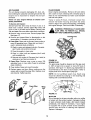
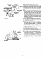
IMPORTANT: This unit is shipped WITHOUT GASOLINE or OIL in the engine. After assembly, see operation section of this manual for proper fuel and engine
oil recommendations.
Flat ---=-//_
Washer | 1_
_ |
5/16" I.D.
_,.-- Hex Lock
Nut 5/16-18
Thread
NOTE: To determine right and left hand sides of your
chipper-shredder,
stand behind the unit with the
engine the farthest away from you. See figure 6.
Your chipper-shredder
has been completely assembled at the factory, except for the hopper assembly
(hopper hood and upper leaf ramp section have been
sub-assembled),
upper guide assembly,
chute
deflector and the catcher bag. The hardware pack
safety glasses and a bottle of oil are also included in
the carton.
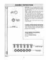
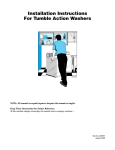
The hardware pack contains the parts shown in figure
1 (shown full size).
TOREMOVE
CHIPPER-SHREDDER
FROMCARTON
Hex Bolt
5/16-18 x 8-3/8" Long
Cut the corners of the carton. Remove all packing
inserts. Roll chipper-shredder out of the carton. Make
certain all parts and literature have been removed
before the carton is discarded.
TOOLS REQUIREDFOR ASSEMBLY
(1)
(2)
(2)
(1)
Phillips Screwdriver
1/2" or Adjustable Wrenches
7/16" or Adjustable Wrenches
Funnel
uss Machine Screws
1/4-20 x 1/2" Long
Hex Lock Nuts
1/4-20 Thread
m
-
q
p
FIGURE 1.
Spacers_
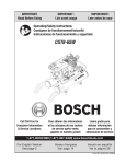
HOWTO SET-UPYOUR CHIPPER-SHREDDER
Housing
MAKE
Hex Bolt
_hb
Chute
Deflector
Hex
Nut
Hand
Knob
\\
\
//
/
/
FIGURE2.
Stop
Washer
Hopper
Door
\
Release
Bar
/
//
Upper
Guide
Assembly
Bolt
8-3/8" Long
Flat Washer
Hex Lock Nut
Inlet
Guide
FIGURE 3.
Hopper Pivot
Door
Bar
Hopper Assembly
Upper
Leaf Ramp
Section
Remove Truss
Screw and Nut
Guide
(Assemble
Assembly
First)
FIGURE 4.
.Plunger
FIGURE 5.
CERTAIN
THE
SPARK
PLUG
AWAY
THE
SPARK
PLUG
WIRE IS FROM
DISCONNECTED
AND MOVED
BEFORE ASSEMBLING
THE CHIPPERSHREDDER.
REFER TO FIGURE 13,
PAGE 11.
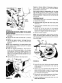
"<-ATTACHING THE CHUTE DEFLECTOR
• Remove the hand knobs and cupped washers from
each side of the discharge opening on the left side
of the chipper-shredder.
• Remove hex lock nut, two spacers and hex bolt
using two 7/16" wrenches from inside the hinge on
top of the housing assembly. Do not remove one
spacer from the hex bolt.
• Place the chute deflector in position on the discharge opening. Insert hex bolt and spacer through
hinge on chute deflector and housing (spacer fits
inside of hinge). See figure 2.
• Place second spacer over hex bolt, inside other
part of hinge. Secure with hex lock nut. Tighten
securely.
• Secure both sides of chute deflector to housing
using hand knobs and cupped washers (cupped side
of washers go against chute deflector).
"<-ATTACHING THE UPPER GUIDE ASSEMBLY
Grasp the upper guide assembly from the sides and
squeeze in and slide it over the inlet guide so the
edges are under the stop washers. Adjust so the
holes in the upper guide assembly are aligned with
the holes in the inlet guide. Insert the hex bolt 8-3/8"
long through the upper guide assembly and the inlet
guide. Secure with flat washer and lock nut.
NOTE: Make certain the upper guide assembly can
pivot by lifting it up until it locks in the raised position.
If it does not pivot freely, loosen the hex lock nut a
turn or two and test.
THE HOPPER ASSEMBLY
Your chipper-shredder
has been shipped with the
upper leaf ramp section attached to the hopper
assembly. See figure 4. Attach the hopper assembly
to the upper guide assembly as follows. Be certain to
place heads of all truss machine screws inside of
hopper assembly.
• Remove one truss machine screw and nut from
each side of hopper assembly as shown in figure 4.
Push hopper pivot door down inside lower part
of hopper as you place hopper assembly (both
pieces) inside upper guide assembly. Replace
truss screws and nuts just removed, using the hole
shown in figure 4, one on each side. Tighten finger
tight only.
NOTE: You may have to squeeze in the sides of the
hopper to start the screws. If you have difficulty aligning the holes, loosen the two screws on the upper end
of the hopper assembly.
• Place the six truss machine screws and nuts found
in hardware pack in the remaining holes of hopper
assembly, alternating sides of the unit and tightening finger tight only.
• After assembling all eight screws, tighten them
securely.
_'-ATTACHING
THE CATCHER BAG
Your chipper-shredder is equipped with a catcher bag
to catch the shredded material.
• To attachthe bag, placethe openingof the bag
overthechutedeflectorso it completely
coversthe
chuteopening.Depressthe plungeron the draw-
string,andpull on the drawstringuntilthe bagis
tightaroundthe chuteopening.Releaseplungerto
lockitintoposition.Seefigure5.
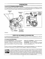
OPERATION
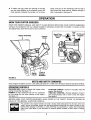
KNOW YOUR CHIPPER-SHREDDER
READ THIS OWNER'S MANUAL AND SAFETY RULES BEFORE OPERATING YOUR CHIPPER-SHREDDER.
Compare the illustrations with your chipper-shredder to familiarize yourself with the location of various controls
and adjustments. Save this manual for future reference.
Fuel
Hopper Assembly
Chipper
Chute
Spark Plug,
Wire and _
Boot
Fill
Cap
Oil Fill and
Dipstick
I
Throttle
Control
Starter
Handle
Front of
ChipperShredder
FIGURE 6.
MEETS ANSI SAFETYSTANDARDS
Sears chipper-shredders
conform to the safety standard B71.6-1982 of the American National Standards Institute.
OPERATINGCONTROLS
RELEASE BAR--Used to release the hopper when
raising or lowering. See figure 10.
PRIMER--Pumps additional fuel from the carburetor
to the cylinder for use when starting a cold engine.
See figure 14.
STARTER HANDLE--Used
to manually start the
engine. See figure 6.
THROTTLE CONTROL--Permits
selection of fast or
slow engine speed, and is used to stop the engine.
See figure 6.
BEFORE USING YOUR CHIPPER-SHREDDER,
AGAIN REFER TO THE "SAFETY
PAGE 2 OF THIS MANUAL. ALWAYS BE CAREFUL.
RULES" AS SHOWN ON
The operation of any chipper-shredder can result in foreign objects being thrown into the eyes, which can
result in severe eye damage. Always wear the safety glasses provided with the chipper-shredder or eye
shields before chipping or shredding, or while performing any adjustments or repairs. We recommend
Wide Vision Safety Mask for over spectacles or standard glasses available at Sears Retail or Catalog
Stores.
TO STOP ENGINE
\
• Move throttle control lever to STOP position. See
figure 6.
No Larger Than
1/2" Diameter
Or 1" Diameter
(Maximum)
• Disconnect spark plug wire and move away from
spark plug to prevent accidental starting while
equipment is unattended. See figure 6.
HOW TO USE YOUR CHIPPER-SHREDDER
Do not attempt to shred or chip any material other
than vegetation found in a normal yard (i.e., branches,
leaves, twigs, etc.).
&
WARNING: THE CHIPPER-SHREDDER
DISCHARGES
MATERIALS WITH CONSIDERABLE
VELOCITY.
KEEP AWAY
FROM THE AREA AROUND THE CHUTE
DEFLECTOR.
ALWAYS
STOP THE
ENGINE AND DISCONNECT THE SPARK
PLUG WIRE WHEN
REMOVING
OR
ATTACHING THE BAG WHEN CHANGING
CONTAINERS OR WHEN REMOVING THE
SHREDDED MATERIAL. WEAR SAFETY
GLASSES AND GLOVES WHENEVER
USING YOUR CHIPPER-SHREDDER.
The chipper-shredder
methods of operation.
is designed
Hopper
Assembly
FIGURE 7.
• Leaves and small twigs can be raked into the hopper assembly when the hopper assembly is lowered to the ground. See figure 8. Small branches
up to 1/2" diameter (recommended)
or 1" diameter (maximum)
can also be fed into the hopper
assembly in this position. See figure 9.
for three different
• Leaves and small branches up to 1/2" diameter
(recommended) or 1" diameter (maximum) can be
fed into the hopper assembly when it is in the
raised position. See figure 7. If it becomes necessary to push material into the chipper-shredder,
use a small diameter stick--NOT YOUR HANDS.
The stick should be small enough that it will be
ground up if gets into the impeller assembly.
WARNING:
DO NOT PUT MATERIAL
LARGER THAN 1/2" IN DIAMETER (RECOMMENDED)
or 1" DIAMETER (MAXIMUM) INTO THE HOPPER ASSEMBLY.
MATERIAL UP TO A MAXIMUM OF 3" IN
DIAMETER
MAY BE FED INTO THE
CHIPPER CHUTE. DO NOT ATTEMPT TO
SHRED OR CHIP ANY MATERIAL LARGER THAN 3" IN DIAMETER. PERSONAL
INJURY OR DAMAGE TO THE MACHINE
COULD RESULT.
U
FIGURE 8.
No Larger Than
1/2" Diameter
Or 1" Diameter
(Maximum)
FIGURE 9.
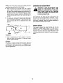
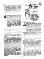
GASAND OIL FILL-UP
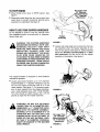
• To lower the hopper assembly, use one hand to
grasp the handle at the top of the hopper assembly
and lift slightly. Pull up on the release bar, and
lower the hopper assembly to the ground. Release
the bar. See figure 10.
---______
Hopper
OIL (Packed with Unit)
Only use high quality detergent oil rated with API
service classification SF, SG or SH. Select the oil's
viscosity grade according to your expected operating
temperature.
Colder
_
---.
_
32°F
Assembly
5W30
• Bulky material, such as stalks or heavy branches,
up to 3" in diameter, should be fed into the chipper
chute. See figure 11.
MAKE CERTAIN
SAE 30
NOTE: Although multi-viscosity oils (5W30, 10W30,
etc.) improve starting in cold weather, these multiviscosity oils will result in increased oil consumption
when used above 32°F. Check your oil level more frequently to avoid possible engine damage from running low on oil.
• Fill engine with oil as follows. Remove oil fill dipstick. See figure 12. With chipper-shredder
level,
use a funnel to fill engine with oi! to FULL mark on
dipstick. Capacity is approximately 21 ounces. Be
careful not to overfill. Tilt chipper-shredder toward
the left (from behind the hopper), then re-level.
Check oil level. Refill to FULL mark on dipstick if
necessary. Replace dipstick and tighten.
FIGURE 10.
WARNING:
_- Warmer
THE CHIP-
PER IN
CHUTE
NOT
USE. DOOR IS CLOSED
WHEN
3" Maximum
Diameter
Oil
Dipstick
Oil
Drain
FIGURE 12.
FIGURE 11.
IMPORTANT:
GAS
• Remove fuel cap and fill fuel tank with about 3
quarts of clean, fresh, lead-free grade automotive
gasoline. DO NOT use Ethyl or high octane gasoline. Be certain container is clean and free from
rust or foreign particles. Never use gasoline that
may be stale from long periods of storage in the
container. Replace fuel cap.
Chipper
Chute
There is a flail screen located inside
the housing in the discharge area. If the flail screen
becomes clogged, remove and clean as instructed in
the Service and Adjustments section. For best performance, it is important to keep the shredding blade
and the chipper blades sharp. If the composition of
the material being discharged changes (becomes
stringy, etc.) or if the rate at which the material is discharged slows down considerably, it is likely that the
shredding blade and/or chipper blades are dull and
need to be sharpened or replaced. Refer to Service
and Adjustments section.
1/2 INCH OF TOP OF FUEL TANK TO
WARNING:
DO NOTAND
FILLTO
CLOSER
PREVENT SPILLS
ALLOW THAN
FOR
FUEL EXPANSION.
IF GASOLINE
IS
ACCIDENTLY SPILLED, MOVE CHIPPERSHREDDER
AWAY FROM AREA OF
SPILL. AVOID CREATING ANY SOURCE
OF IGNITION UNTIL GASOLINE VAPORS
HAVE DISAPPEARED.
10
• Attach spark plug wire and rubber boot to spark
plug. See figure 13.
Check the fuel level periodically to avoid running out
of gasoline while operating the chipper-shredder. If the
unit runs out of gas as it is shredding or chipping, it
may be necessary to unclog the unit before it can be
restarted, Refer to "Removing the Flail Screen" in
SERVICE AND ADJUSTMENT section.
•
lever in FAST position
NOTE: Primer may be needed to restart a warm
engine after a short shut-down.
• Grasp starter handle (see figure 13) and pull rope
out slowly until engine reaches start of compression cycle (rope will pull slightly harder at this
point). Let the rope rewind slowly.
NOTE: A noise will be heard when finding the start of
the compression cycle. This noise is caused by the
flails and fingers which are part of the shredding mechanism falling into place, and should be expected. In
addition, the flails and fingers will be noisy after the
engine is started, until the impeller reaches full speed.
NEVER USE ENGINE OR CARBURETOR CLEANER PRODUCTS IN THE FUEL TANK OR PERMANENT DAMAGE MAY OCCUR.
Fuel
Fill Cap
control
• Push primer two or three times prior to starter operation. See figure 14. Use sharp pushes and wait
about two seconds between each push. In cold
weather (50°F or below), push primer five times.
WARNING: EXPERIENCE INDICATES THAT ALCOHOL BLENDED FUELS (CALLED GASOHOL OR
USING ETHANOL OR METHANOL) CAN ATTRACT
MOISTURE WHICH LEADS TO SEPARATION AND
FORMATION
OF ACIDS DURING
STORAGE.
ACIDIC GAS CAN DAMAGE THE FUEL SYSTEM
OF AN ENGINE WHILE IN STORAGE. TO AVOID
ENGINE
PROBLEMS,
THE FUEL
SYSTEM
SHOULD BE EMPTIED OR TREATED WITH FUEL
STABILIZER
BEFORE STORAGE FOR 30 DAYS
OR LONGER. USE FRESH FUEL NEXT SEASON.
SEE "STORAGE"
SECTION FOR ADDITIONAL
INFORMATION•
Spark Plug,
Place the throttle
(UP).
•
Oil Fill and
Dipstick
Pull rope with a rapid, continuous, full arm stroke.
Keep a firm grip on starter handle. Let rope rewind
slowly. Do not let starter handle snap back against
starter.
NOTE: To prevent the unit from sliding, place your
foot against the tire.
Boot
• Repeat
fires.
preceding
two instructions
until engine
NOTE: If engine does not start after three attempts,
push primer two times and pull starter rope again.
Throttle
Control
FIGURE 13.
Primer
TO STARTENGINE
WARNING:
_k
BE SURE
NO ONE OTHER
_
FIGURE 14.
THAN
THE CHIPPER-SHREDDER
OPERATOR
IS STANDING
NEAR THE
WHILE
STARTING
OR OPERATING.
DO NOT
OPERATE THIS CHIPPER-SHREDDER
UNLESS THE CHUTE DEFLECTOR HAS
BEEN PROPERLY INSTALLED
AND IS
SECURED WITH THE HAND KNOBS.
TO STOP ENGINE
• Move throttle control lever to STOP position (DOWN).
• Disconnect spark plug wire and move away from
spark plug to prevent accidental starting while
equipment is unattended.
11
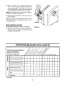
CUSTOMER
MAINTENANCE SCHEDULE
FILL IN DATES
AS YOU COMPLETE
REGULAR SERVICE
RESPONSIBILITIES
/
DATES
SERVICE
p-
to
4
Oil Pivot Points
a
O
n-
*/
Clean Shredder
D,.
Check Engine Oil
4
-_/
Change Engine Oil
_J
*J
Service Air Cleaner
,,=,
Clean Engine Cylinder
_'
4'
Spark Plug
_
-_
Muffler
_f
_/ CHECK
GENERALRECOMMENDATIONS
_
AND DISCONNECT
THE SPARK PLUG
WARNING: ALWAYS STOP THE ENGINE
WIRE
BEFORE
PERFORMING
ANY
MAINTENANCE OR ADJUSTMENTS,
• Periodically
are tight.
•
Colder
<
32°F
5W30
_
Warmer
SAE 30
NOTE: Although multi-viscosity oils (SE30, 10W30,
etc.) improve starting in cold weather, these multi- viscosity oils will result in increased oil consumption
when used above 32°F. Check your oil level more frequently to avoid possible engine damage from running low on oil.
check all fasteners and be sure they
Follow the Maintenance Schedule above.
CHIPPER-SHREDDER
Your four-cycle engine will normally consume some
oil--therefore, check engine oil level regularly approximately every five hours of operation and before each
usage. Stop engine and wait several minutes before
checking oil level. With engine level, the oil must be to
FULL mark on dipstick (refer to figure 12). Change
engine oil after the first five hours of operation, and
every twenty-five hours thereafter.
LUBRICATION
Lubricate the pivot points on the release bar, hopper
assembly, chute deflector and chipper chute once a
season using a light oil.
CLEANING
• The chipper-shredder may be cleaned by running
water from a hose through the hopper assembly
and chipper chute with the engine running. Allow
the chipper-shredder to dry thoroughly.
To Drain Oil:
• Drain oil while engine is warm.
• Wash the bag periodically with water. Allow to dry
thoroughly in the shade. Do not use heat.
a. Remove oil drain plug. Refer to figure 12. Catch
oil in a suitable container.
ENGINE
ENGINE OIL
Only use high quality detergent oil rated with API
service classification SF, SG or SH. Select the oil's
viscosity grade according to your expected operating
temperature.
•
•
12
b. When engine is drained of all oil, replace drain
plug securely.
Refill with fresh oil. Refer to GAS AND OIL FILLUP section.
Replace dipstick.
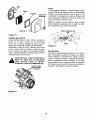
AIR CLEANER
CLEAN ENGINE
Clean engine periodically. Remove dirt and debris
with a cloth or brush. Cleaning with a forceful spray of
water is not recommended as water could contaminate the fuel system.
The air cleaner prevents damaging dirt, dust, etc.,
from entering the carburetor and being forced into the
engine and is important to engine life and performance.
Never run your engine without
pletely assembled.
air cleaner com-
Yearly or every 25 hours, whichever occurs first,
remove the blower housing and clean the areas
shown in figure 16 to avoid overspeeding, overheating
and engine damage. Clean more often if necessary.
To Service Air Cleaner:
Service foam filter after every 25 hours of use, or at
least once a season. Service paper filter every 100
hours of use, or at least once a season. Service foam
filter and paper filter more often under dusty conditions.
FLER AREAPERIODICALLY
TO REMOVE ALL
GRASS,
4j_WARNING:
CLEAN
MUFDIRT AND COMBUSTIBLE DEBRIS.
• Remove wing nut and cover. Remove paper filter.
See figure 15.
Cooling Fins
• Remove and inspect filters for discoloration or dirt
accumulation. If necessary, service as follows.
• Foam filter: Clean and re-oil every three months or
every 25 operating hours. Clean and re-oil daily if
used in extremely dusty conditions.
• Wash in water and detergent solution. Squeeze
(don't twist) until all dirt is removed.
• Rinse thoroughly in clear water.
• Wrap in a clean cloth and squeeze (don't twist)
until completely dry.
• Saturate with engine oil. Squeeze (don't twist) to
distribute oil and remove excess oil.
FIGURE 16.
SPARK PLUG
• Paper filter: Replace once a year or every 100
operating hours, or more often if used in extremely
dusty conditions.
The spark plug should be cleaned and the gap reset
to .030" at least once a season or every 50 hours of
operation. See figure t7. Spark plug replacement is
recommended at the start of each season. Refer to
• Clean inside of base and cover thoroughly.
• Replace paper and foam filters, making sure the
screen side is toward the paper filter. Replace cover
and wing nut. Tighten securely.
engine parts list for correct spark plug type.
NOTE: Do not sandblast spark plug. Spark plug
should be cleaned by scraping or wire brushing and
washing with a commercial solvent.
Base
.030" Feeler Gauge
Paper
Filter
/
Foam Filter
Wing
Plug
FIGURE 17.
MUFFLER
Do not operate the chipper-shredder without a muffler
or tamper with the exhaust system. Damaged mufflers
or spark arresters could create a fire hazard. Inspect
periodically, and replace if necessary. If your engine
is equipped with a spark arrester screen assembly,
remove every 50 hours for cleaning and inspection.
Replace if damaged.
Cover-----.._
FIGURE 15.
13
STORAGE
Prepare your chipper-shredder for storage at the end
of the season or if the unit will not be used for 30 days
or more.
,_
• Drain the fuel tank.
• Start the engine and let it run until the fuel lines and
carburetor are empty.
• Never use engine or carburetor cleaner products in
the fuel tank or permanent damage may occur.
• Use fresh fuel next season.
WITH FUEL IN THE FUEL TANK INSIDE
WARNING:
NEVER STORE MACHINE
OF BUILDING
WHERE
FUMES
MAY
REACH AN OPEN FLAME OR SPARK, OR
WHERE
IGNITION
SOURCES
ARE
PRESENT SUCH AS HOT WATER AND
SPACE HEATERS, FURNACES, CLOTHES
DRYERS, STOVES, ELECTRIC MOTORS,
ETC.
NOTE: Fuel stabilizer is an acceptable alternative in
minimizing the formation of fuel gum deposits during
storage. Add stabilizer to gasoline in fuel tank or storage container. Always follow the mix ratio found on
stabilizer container. Run engine at least 10 minutes
after adding stabilizer to allow the stabilizer to reach
the carburetor. Do not drain the gas tank and carburetor if using fuel stabilizer.
NOTE: A yearly check-up by your local Sears Service
Center is a good way to make certain your chippershredder will provide maximum performance for the
next season.
•
Drain all the oil from the crankcase (this should be
done after the engine has been operated and is still
warm) and refill the crankcase with fresh oil.
•
If you have drained the fuel tank, protect the inside
of the engine as follows. Remove spark plug, pour
approximately 1/2 ounce (approximately one tablespoon) of engine oil into cylinder and crank slowly
to distribute oi!. Replace spark plug.
CHIPPER-SHREDDER
• Clean the chipper-shredder
thoroughly.
• Wipe unit with an oiled rag to prevent rust (use a
light oil or silicone).
ENGINE
IMPORTANT:
IT IS IMPORTANT
TO PREVENT
GUM DEPOSITS FROM FORMING IN ESSENTIAL
FUEL SYSTEM PARTS SUCH AS CARBURETOR,
FUEL FILTER, FUEL HOSE, OR TANK DURING
STORAGE. ALSO, EXPERIENCE INDICATES THAT
ALCOHOL BLENDED FUELS (CALLED GASOHOL
OR USING
ETHANOL
OR METHANOL)
CAN
ATTRACT MOISTURE WHICH LEADS TO SEPARATION AND FORMATION OF ACIDS DURING STORAGE. ACIDIC GAS CAN DAMAGE THE FUEL SYSTEM OF AN ENGINE WHILE IN STORAGE.
OTHER
•
Do not store gasoline from one season to another.
•
Replace your gasoline can if your can starts to rust.
Rust and/or dirt in your gasoline will cause problems.
• Store unit in a clean, dry area. Do not store next to
corrosive materials, such as fertilizer.
NOTE: If storing in an unventilated or metal storage
shed, be certain to rustproof the equipment by coating
with a light oil or silicone.
SERVICE & ADJUSTMENT
WARNING: ALWAYS STOP ENGINE AND
DISCONNECT SPARK PLUG WIRE AND
MOVE IT AWAY FROM SPARK PLUG
BEFORE PERFORMING
ANY ADJUSTMENTS OR REPAIRS.
Loosen the two hand knobs on each side of the
chute deflector. Lift the chute deflector up, and tie it
out of the way.
REMOVING THE FLAIL SCREEN
• Remove two hairpin clips from the clevis pins which
extend through the housing. Remove the clevis
pins. Lift the flail screen from inside the housing.
See figure 18.
If the discharge area becomes clogged, remove the
flail screen and clean area as fo!lows.
• Clean the screen by scraping
water. Reinstall the screen.
• Stop the engine, make certain the chipper-shredder
has come to a complete stop and disconnect spark
plug wire from the spark plug before unclogging the
chute.
or washing
with
NOTE: Be certain to reassemble the flail screen with
the curved side down as shown in figure 18.
14
Replace or sharpen blades. If sharpening, make certain to remove an equal amount from each blade.
Reassemble in reverse order.
Hairpin
Clips,
Clevis
Pins
_Hex
Nuts,
Washers
Make certain blades are reassembled with the sharp
edge facing the direction shown in figure 18 (sharp
edge is assembled toward the slotted opening in the
impeller assembly). Torque bolts and nuts to 250-350
inch pounds.
SHREDDING BLADE
The shredding blade may be removed for sharpening
or replacement as follows.
Flail
Screen
• Disconnect spark plug wire and move it away from
spark plug.
• Lower the hopper assembly. Block up the housing.
See figure 20.
Chute
• Remove the six hex lock nuts and lock washers
Hand Knobs
FIGURE 18.
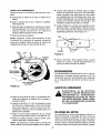
SHARPENING
ORREPLACING
THEBLADES
CHIPPER BLADES
from the housing weld bolts using a 1/2" wrench.
Separate the chipper-shredder into two halves.
• Remove the back-up plate.
NOTE: When reassembling, make certain the opening on the back-up plate is toward the bottom of the
unit. The back-up plate may be reversed to provide a
new cutting edge.
• Disconnect spark plug wire and move it away from
spark plug.
• Remove the flail screen as instructed in previous
section.
• Remove the chipper chute by removing three hex
nuts and washers. A 1/2" wrench is required. See
figure 18.
Allen
Screws
NOTE: When reassembling, the cupped washer goes
on the bottom of the chipper chute with the cupped
side against the chute.
• Rotate the impeller assembly by hand until you
locate one of the chipper blades in the chipper
chute opening. Remove the blade, using a 3/16"
allen wrench on the outside of the blade and 1/2"
wrench on the impeller assembly (inside the housing). See figure 19.
Pipe
Sharp Ed!
• Remove the other blade in the same manner.
FIGURE 20.
Torque
Wrench
• Loosen the two hand knobs and cupped washers
which secure the chute deflector, and raise the
chute deflector.
• Insert a 1/2" or 3/4" diameter pipe through the flail
screen into the impeller to keep it from turning, or
remove the flail screen and insert a piece of wood
(2 x 4) into the chute opening.
\
• Remove the two outside screws on the blade,
using a 3/16" allen wrench and a 1/2" wrench.
\\
• Remove the blade by removing the center bolt, lock
washer and flat washer.
FIGURE 19.
15
NOTE:Usecautionwhenremoving
thebladetoavoid
contacting
theweldboltsonthe housing.
• Whensharpeningthe blade,follow the original
angleof grindas a guide.It is extremelyimportant
thateachcuttingedgereceivesanequalamountof
grindingto preventan unbalanced
blade.An unbalancedbladewill causeexcessivevibrationwhen
rotatingat highspeedsandmaycausedamageto
theunit.
• Thebladecanbetestedfor balanceby balancing
it
ona roundshaftscrewdriver
or nail.Removemetal
fromthe heavysideuntilit is balancedevenly.See
figure21.
Nail _\
_
t
CARBURETORADJUSTMENT
WARNING:
,_
IF ANY ADJUSTMENTS
ARE
MADE
ENGINE
THE
ENGINE TO
IS THE
RUNNING
(E.G.WHILE
CARBURETOR), KEEP CLEAR OF ALL MOVING
PARTS. BE CAREFUL OF HEATED SURFACES AND MUFFLER.
The carburetor has been pre-set at the factory and
should not require adjustment.
However, if your
engine does not operate properly due to suspected
carburetor problems, take your chipper-shredder
to
your nearest SEARS Service Center.
ENGINESPEED
Your engine speed has been factory set. Do not
attempt to increase engine speed or it may result in
personal injury. If you believe the engine is running
too fast or too slow, take your chipper-shredder to the
nearest SEARS Service Center for repair and adjustment.
Blade
FIGURE 21.
• When reassembling the blade, tighten to between
550 and 650 inch pounds, or lacking torque
wrench, tighten securely.
FLAILS
The flails, located inside the housing,
may be
reversed when they become dull. It is suggested that
this procedure be performed by your nearest Sears
Service Department.
16
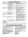
TROUBLE SHOOTING
PROBLEM
POSSIBLE CAUSE(S)
CORRECTIVE
Engine fails to start
• Fuel tank empty, or stale fuel.
• Spark plug wire disconnected.
• Engine not primed correctly.
• Throttle control not in correct
starting position.
• Faulty spark plug.
• Fill tank with clean, fresh fuel.
• Connect wire to spark plug.
• Follow priming instructions in operation section.
• Move throttle control to FAST position.
Loss of power;
operation erratic
•
•
•
Spark plug wire Joose.
Blocked fuel line or stale fue!.
Water or dirt in fuel system.
•
Carburetor out of adjustment.
•
Dirty air cleaner.
• Connect and tighten spark plug wire.
• Clean fuel line; fill tank with clean fresh gasoline.
• Disconnect fuel line at carburetor to drain fuel
tank. Refill with fresh fuel.
• Adjust carburetor or contact your SEARS
Service Center.
• Service air cleaner. See Customer Responsibilities
section of this manual.
Engine overheats
• Clean, adjust gap or replace.
Carburetor not adjusted
propedy.
• Engine oil level low.
• Contact your SEARS Service Center.
•
Fill crankcase with proper oil.
Too much vibration
•
Loose parts or damaged
impeller,
•
Stop engine immediately and disconnect
spark plug wire. Tighten all bolts and nuts.
Make all necessary repairs. If vibration continues,
have unit serviced by a SEARS Service Center.
Unit does not
discharge
•
Discharge chute clogged.
•
•
Foreign object lodged in impeller.
•
Stop engine immediately and disconnect
spark plug wire. Clean flail screen and inside
of blower housing. See Service/Adjustments
section of this manual.
Stop engine immediately and disconnect
spark plug wire. Remove lodged object.
•
Shredding blade and/or chipper
blades dull.
•
Rate of discharge
slows considerably or
composition of
discharged material
changes
NOTE:
For repairs beyond
•
ACTION
the minor adjustments
listed above, please
Sharpen or replace shredding and chipper
blades.
contact
your nearest
HOW TO ORDER REPLACEMENT
will be
The model number for the engine will be found on the
blower housing of the engine.
All parts listed herein may be ordered through Sears,
Roebuck and Co. Service Centers and most Retail
Stores.
Center.
PARTS
IF YOU NEED REPAIR
SERVICE OR PARTS:
WHEN ORDERING REPAIR PARTS, ALWAYS GIVE
THE FOLLOWING INFORMATION:
*PRODUCT
Service
Your Sears merchandise has added value when you
consider that Sears has service units nationwide
staffed with Sears trained technicians...professional
technicians specifically trained on Sears products,
having the parts, tools and the equipment to insure
that we meet our pledge to you..."we service what we
sell."
Each chipper-shredder
has its own model number.
Each engine has its own model number.
The model number for your chipper-shredder
found on a label attached to the frame.
SEARS
REPAIR SERVICE
1-800-4-REPAIR
- "5 H.P. Chipper-Shredder"
*MODEL NUMBER - 247.795850
(1-800-473-7247)
*ENGINE MODEL NO. - 143.955003
ORDERING
PARTS
1-800-FON-PART
(1-800-366-7278)
*PART NUMBER
*PART DESCRIPTION
17
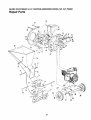
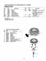
SEARS
CRAFTSMAN
5 H.P. CHIPPER-SHREDDER
MODEL
NO. 247.795850
Repair Parts
22 3231
\
23
\
\
\
l
56
!
47
t
!
57
51
\
77
78
_6
_5
63
\ z6
5,_
79
t
59
34
61
18
35
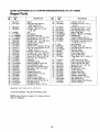
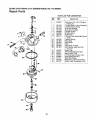
SEARS
CRAFTSMAN
5 H.P. CHIPPER-SHREDDER
MODEL
NO. 247.795850
Repair Parts
CEY
_10.
PART
NO.
i KEY
I NO,
DESCRIPTION
!
742-0571
710-1254
4
5
6
7
8
9
10
11
12
13
14
15
16
17
18
19
20
22
23
24
25
26
27
28
29
30
31
32
33
34
35
36
37
736-0217
736-0247
11459B
711-0564
711-0833B
711-0834A
715-0249
736-0192
681-0030
781-0490
710-1054
712-0411
736-0119
710-0825
736-0142
750-0793
711-0835
712-0291
714-3010
781-0457
714-0149B
781-0480
712-3010
736-0242
720-0170
747-0744A
732-0542
781-0489
781-0475
736-0170
712-3010
781-0510A
710-0157
Blade
Hex Patch Bolt 3/8-24 x
2.25" Lg. (Gr. 8)
L-Wash. 3/8" I.D.H.D.
FI-Wash..406" I.D. x 1.25"
O.D. Hdn.
Flait
Flail Spacer
Clevis Pin .496" Dia.
Flail Spacerw/.160" Dia. Hole
Spring Roll Pin 1.12" Lg.
FI-Wash..531" I.D. x .94" O.D.
Impeller Ass'y. Comp.t
Chipper Blade
Flat Hd. Scr. 5/16-24 x .75" Lg.
Hex Top L-Nut 5/16-24 (Gr. 5)
L-Wash. 5/16" I.D.*
Hex Bolt 1/4-20 x 3.75" Lg.*
FI-Wash..281" I.D. x .50" O.D.
Chute Hinge Spacer 1.66" Lg.
Clevis Pin .5" Dia. x 4.62" Lg.
Hex Ctr. L-Nut 1/4-20 Thd.
Cotter Pin
Shredder Screen
Internal Cotter Pin 3/8" Dia.
Chute Deflector Ass'y.
Hex Nut 5/16-18 Thd. (Gr. 5)
Bell-Wash..345" I.D. x .88"
Hand Knob
Chipper Door Rod
Torsion Spring 1.14" Lg.
Chipper Door
Chipper Chute Ass'y.
Spec. L-Wash. 5/16" I.D.
Hex Nut 5/16-18 Thd. (Gr. 5)
Shredder Frame
Hex Bolt 5/16-24 x .75" Lg.
I
!
38
39
_ 40
41
42
43
I 44
_ 45
'j 46
i 47
48
NOTE: Specifications
notice or obligation.
to change
710-0442
681-0004
781-0474A
735-0639
143.955003
747-0531A
732-0546
712-0429
710-0601
11480
736-0264
710-0542
781-0487B
16522B
781-0494
16524B
710-0286
57
58
59
61
62
63
75
76
77
78
79
712-0107
11461B
726-0214
750-0786
738-0814
734-1600
732-0629
747-0747
781-0492
781-0493
726-0106
764-0199A
723-0400
770-8901L
Be Purchased Locally.
subject
736-0119
710-3008
49
50
51
52
53
54
55
56
tlncl. Ref. 1,6, 7, 8, 9, 10, 11, 12, 13, 14
*Common Hardware---May
PART
NO.
without
19
DESCRIPTION
L-Wash. 5/16" I.D.*
Hex Bolt 5/16-18 x .75" Lg.
(Gr. 5)
Hex Bolt 5/16-18 x 1.5" Lg.*
Flail Housing Ass'y.--L.H.
Flail Housing Ass'y.--R.H.
Spark Plug Boot
Engine--Model 143.955003
Release Bar
Torsion Spring 1.06" Lg.
Elastic Lock Nut 5/16-18 Thd.
Hex Wash. Hd. Self-Tap Scr.
5/16-18 x .75" Lg.
Stop Washer
FI-Wash. 5/16" I.D.
Hex Bolt 5/16-18 x 8.38" Lg.
Back-Up Plate
Inlet Guide Ass'y.
PivotHopper Hood
Upper Guide Ass'y.
Truss Mach. Scr. 1/4-20 x .5"
Lg.
Hex L-Nut 1/4-20 Thd.
Upper Leaf Ramp Section
Push Cap 5/8" Dia. Rod
Spacer .64" I.D. x .38" Lg.
Shredder Axle
Wheel Ass'y. Comp.
Torsion Spring
Hopper Door Rod
Hopper--Pivot Door
Hopper Lockout Brkt.
Cap Speed Nut 1/4" Rod
Bag (Not Shown)
Safety Glasses (Not Shown)
Owner's Manual
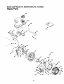
SEARS
CRAFTSMAN
5 H.P. ENGINE
MODEL
NO. 143.955003
Repair Parts
135
\ \
//
\
\
\
\
g
125
,
1
I
I
2O
SEARS
CRAFTSMAN
5 H.R ENGINE
MODEL
NO. 143.955003
Repair Parts
f
65
3_I
60
301
290
3/_Z
292
I01
IOO
f
26
370A
<
313
285
Z61
261AI
260
262
f
93
390
2OO
287
Z62
215
21
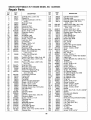
SEARS
CRAFTSMAN
5 H.P. ENGINE
MODEL
NO. 143.955003
Repair Parts
KEY
NO.
PART
NO.
1
2
4
36617
26727
31857
5
14
15
16
17
18
19
20
25
25A
26
28
30
35
36
37
38
40
40
30969
28277
30589
36618
29916
650548
36639
326O0
36621
36622
30200
30322
36619
29826
29918
29216
29642
35544A
35545A
4O
35546
41
41
35541
35542
41
35543
42
42
42
43
45
35547A
35548A
35549
20381
32875A
46
48
49
5O
60
64
65
69
70
72
75
8O
81
82
83
86
89
90
92
93
100
101
103
110
32610A
35616
36611
36676
36623
650833
30200
36624
36625
27642
27897
30574A
30590A
30591
36057
650488
610961
611205
650815
650816
34443A
610118
651007
34231
DESCRIPTION
Cylinder (Incl. 2, 20 & 72)
Dowel Pin
Oil Drain Extension (1/4-18 x
4-1/2")
Extension Cap
Washer
Governor Rod
Governor Lever
Governor Lever Clamp
Screw, 8-32 x 5/16"
Extension Spring
Oil Seal
Air Baffle (Left)
Air Baffle (Right)
Screw, 10-24 x 9.16"
Lock Nut, 8-32
Crankshaft
Screw, 10-32 x 3/4"
Lock Washer
Lock Nut, 10-32
Retaining Ring
Piston, Pin & Ring Set (Std.)
Piston, Pin & Ring Set.
(.010" O.S.)
Piston, Pin & Ring Set.
(.020" O.S.)
Piston & Pin Ass'y. (Std.) (Incl. 43)
Piston & Pin Ass'y. (.010" O.S.)
(Incl. 43)
Piston & Pin Ass'y. (.020" O.S.)
(Incl. 43)
Ring Set (Std.)
Ring Set (.010" O.S.)
Ring Set (.020" O.S.)
Piston Pin Retaining Ring
Connecting Rod Ass'y.
(Incl. 46 & 49)
Connecting Rod Bolt
Valve Lifter
Oil Dipper
Camshaft
Blower Housing Extension
Screw, 1/4-20 x 1-3/16"
Screw, 10-24 x 9/16"
Cylinder Cover Gasket
Cylinder Cover (Incl. 75 thru 83)
Oil Drain Plug
Oil Seal
Governor Shaft
Washer
Governor Gear Ass'y. (Incl. 81)
Governor Spool
Screw, 1/4-20 x 1-1/4"
Flywheel Key
Flywheel
Belleville Washer
Flywheel Nut
Solid State Ignition
Spark Plug Cover
Screw, Torx T-15, 10-24 x 15/16"
Ground Wire
22
KEY
NO.
PART
NO.
119
120
125
! 25
36626
36628
36471
36472
126
126
29314B
29315C
130
130A
135
150
151
153
154
155
157
158
159
160
161
161A
173
178
182
184
185
200
206
207
209
215
223
224
238
239
240
245
245A
250
251
252
260
261
261A
262
275
277
278
279
280
285
287
290
292
300
301
305
307
308
309
650912
650999
34645
31672
31673
36649
650913
35624A
650914
36629
35626
36630
651008
651012
36675
650852
650451
26756
36631
36637
620973
36632
650821
36638
650451
36581
38820
27272A
36633
36046
36634
36635
650886
650821
36636
651008
650821
651008
36641
651009
36674
650852
36642
35985B
-30705
26460
36643
36246
35554
35499
36651
651011
DESCRIPTION
Cylinder Head Gasket
Cylinder Head
Exhaust Valve (Std.) (Incl. 151)
Exhaust Valve (1/32" O.S.)
(IncI. 151)
Intake Valve (Std.) (Incl. 151)
Intake Valve (1/32" O.S.)
(Incl. !51)
Screw, 5/16-18 x 1-1/2"
Screw, 5/16-18 x 2-41/64"
Resistor Spark Plug (N4C)
Valve Spring
Valve Spring Cap
Push Rod Guide
Rocker Arm Stud
Rocker Arm
Nut, 1/4-28
Push Rod
Rocker Arm Cover Gasket
Rocker Arm Cover
Screw, 1/4-20 x 31/64"
Stud
Breather Tube
Nut, 1/4-20
Screw, 1/4-20 x 1"
Carburetor to Intake Pipe Gasket
Intake Pipe
Control Bracket (Incl. 206 & 215)
Terminal
Throttle Link
Screw, 10-32 x 1/2"
Control Knob
Screw, 1/4-20 x 1"
Intake Pipe Gasket
Screw, 10-32 x 1/2"
Air Cleaner Gasket
Air Cleaner Body (Incl. 239)
Air Cleaner Filter
Air Cleaner Filter
Air Cleaner Cover
Wing Nut
Screw, 10-32 x 1/2"
Blower Housing
Screw, 1/4-20 x 31/64"
Screw, 10-32 x 1/2"
Screw, 1/4-20 x 31/64"
Muffler
Screw, Torx T-30, 1/4-20 x 2-9/32"
Spacer
Nut and Lock Washer
Heat Shield
Starter Cup
Rivet (Can be purchased locally)
Fuel Line
Fuel Line Clamp
Fuel Tank (Incl. 301)
Fuel Cap
Oil Fill Tube
"0" Ring
Fill Tube Clip
Screw, 10-32 x 5/16"
SEARS
CRAFTSMAN
5 H.P. ENGINE
MODEL
NO. 143.955003
Repair Parts
KEY
NO.
PART
NO.
310
313
325
327
341
342
370A
370B
360
36640
34080
29443
35392
36644
651010
36261
33107
640004
DESCRIPTION
Dipstick
Spacer
Wire Clip
Starter Plug
Fuel Tank Bracket
Screw, 1/4-20 x 7/8"
Lubrication Decal
Speed Control Decal
Carburetor (Incl. 184)
KEY
NO.
PART
NO.
390
400
590736
36627
416
36085
417
650760
DESCRIPTION
Rewind Starter
Gasket Set (Incl. Items Marked PK
in Notes)
Incl. (1) each of 26756, 27272A,
29673, 35626, 36526, 36581,
36624, 36626
Spark Arrestor Kit (Incl. 417)
(Optional)
Screw, 8-32 x 3/8"
RPM Setting:
High Speed: 3450 to 3750
Low Speed: 2000 to 2300
PARTS LIST FOR RECOIL STARTER
KEY
NO.
1
2
3
4
5
6
7
8
11
12
13
PART
NO.
590736
590599A
590600
590696
590601
590697
590698
590699
590700
590705
590535
590701
DESCRIP_ON
Rewind Starter
Spring Pin (Incl. 4)
Washer
Retainer
Washer
i Brake Spring
Starter Dog
Dog Spring
Pulley & Rewind Spring Ass'y.
Starter Housing Ass'y.
Starter Rope (98" x 9/64" Dia.)
Starter Handle
,._1t
13
m8
°-fo
23
SEARS
CRAFTSMAN
5 H.P. ENGINE
MODEL NO. 143.955003
Repair Parts
PARTS LIST FOR CARBURETOR
KEY
NO.
z_J
24
PART
NO.
--
640004
1
2
4
5
6
7
16
17
631615
631767
631184
631183
640009
650506
632164
650417
18
25
27
28
29
30
630766
631867
631024
632019
631028
631021
31
35
36
37
40
44
47
48
631022
36045
640007
632547
640008
27110
630748
631027
DESCRIPTION
Carburetor (incl. 184 of Engine
Parts List)
Throttle Shaft & Lever Assembly
Throttle Return Spring
Dust Seal Washer
Dust Seal (Throttle)
Throttle Shutter
Shutter Screw
Fuel Fitting
Throttle Crack Screw/Idle Speed
Screw
Tension Spring
Float Bowl
Float Shaft
Float
Float Bowl "O" Ring
Inlet Needle, Seat, and Clip
(Incl. 31)
Spring Clip
Primer Bulb/Retainer Ring
Main Nozzle Tube
"O" Ring, Main Nozzle Tube
High Speed Bowl Nut
Bowl Nut Washer
Welch Plug, Idle Mixture Well
Welch Plug, AtmosPheric Vent
tlANUALDEI
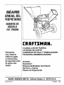
'ROPIErARIO
NUMERO DE
MODELO
247.795850
CRRFTSMRN®
Precauci6n:
Lea y observe
todas las reglas
y instrucciones
de seguridadantes
de operar este
equipo
5 CABALLOS DE FUERZA
3 ETAPAS DE CORTE
CUBRIDOR DE PAJA Y EMBOLSADOR
PICADO RA- DESM EN UZADO RA
Armado
Operacibn
Responsabilidades
del Cliente
Servicio y Ajuste
Piezas de Reparacibn
SEARS,ROEBUCKAND CO., HoffmanEstates, IL 60179 U.S.A.
)reso en U.S.A.
770-8901L
8/95
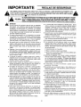
IMPORTANTE
_)
REGLAS DE SEGURIDAD
A
EVITARPELIGROS
PARAELOPERADOR
Y OTROS.LEALASSIGUIENTES
INSTRUOOIONES
DEESTEMANUALANTESDEINSTALAR
EL EQUIPODEILUMINACION.FALTADEOBEDECER
ESTASINSTRUCCtONES
PUEDE
RESULTAR
EN DA_IOPERSONAL.
ESTESIMBOLOINDICAINSTRUCCIONES
IMPORTANTES
PARASU
SEGURIDAD.DEBEN
SEGUIRSE
RIGUROSAMENTE
PARA AL
CUANDO
VEAESTESIMBOLO_IjPRESTE
ATENC!ON
A SUADVERTENCIA.
PELIGRO: que concualquierm_quina,error o falta de cuidadopor partedel operadorpuederesultaren lesiones
I _1_
serias.
El picadora-desmenuzadora
es capazde
cortardedos,manesy
de arrojarobjetos.
La falta
de
Supicadora-desmenuzadora
fuedisefiado
para que
se opereseglinlas reglasde
este manual.
AI igual
atenci6na lassJguientes
instrucciones
deseguridadpuederesultarenlesionesseriaso causarla muerte.
0PERACION
Leaeste manualdel propietarioantes de tratar de ensamblar
estam_quina. Lea,cornprenday sigatodas lasinstruccionesde
la m_quinay del manualantes de ta operaci6n. Es necesario
familiarizarsecon los controlesy el use correctode la mdquina
antesde ponerlaen funcionamiento.Mantengaeste manualen
un lugar seguropara poder consultarlocome sea necesarioy
parahacerel pedidode repuestos.
• Su picadora-desmenuzadora
es una herramientamuy potente,
no un juguete+Per Iotanto, essumamenteimportantemanejarIo siemprecon muchaprecauci6n+Su unidadha side disedada
para cumplir dos funciones; para picar y triturar vegetaci6n
comQnde jardines. Nola utiliceparaningunaotrafunci6n.
• No permita que los nifios menores de 16 aries utilicen la
m_quina. Nifiosmayoresde 16 ariesdebenoperarlasolamente
bajo la supervisi6nde un adulto. Sntamentepersonasresponsables que saben estas reglas de seguridad deben usar su
unidad.
• Mantengael _rea de operacioneslibre de personas,sobretodo
nifios peque_osy animalesdomdsticos.Apagueel motor cuando seencuentrencercade la unidad. Mantengael _readetrabajo limpiay libre de ramas u obstdculosque puedenhacer que
ustedsetropieceo caiga.
• AI alimentarel materiala la mdquina,tenga mucho cuidadoy
aseg_resede que no vayanincluidospedazosde metales,rocas,
botetlas, latas u otros objetos. Lo centrario puede causar
lesionesal operarioo dafiosa la mAquina.
• Utilice siempreanteojos de seguridadclurantela operaci6ny
siempre que efectt_eun ajuste o reparacidn,para protegerlos
ojosde objetosquepuedenserarrojadosper la mdquina
• Use zapatosde suelagruesay pantaionesy camisaajustados
que cubran per complete el cuerpo. Es recomendableusar
betas o zapatoscon punterade acero. No use ropa suelta ni
alhajasy fije el cabellode maneraque quedearribade los hombres ya que se puedenatorar en el aparato. Nunca opere la
m_quinadescalzo,consandaliaso entenis. Useguantesal alimentarel materialal canaldel picadoro a la tolvadel triturador.
• Nuncametalas manes,los pieso cuatquierpartedel cuerpoen
la tolva del triturador,en el canaldel picador,en la aberturade
descargao cereaa cualquierpiezaen movimientomientrasque
el motor esteencendido. Mant6ngasesiemprelejosde la aberturn de descarga.Si necesitaempujarel materialen la tolva del
triturador o en el canaldel picador, use un pale de di_metro
pequeSo,NOSUSMANES.
• Si per algdn motive necesita desatrancar el bocatoma de
alimentaci6no lasaberturasde descarga,o si necesitainspeccionar o reparar cualquierparte de la m_quinaen donde una
piezaenmovimientopuedeentraren contactocon el cuerpoo la
ropa, detengala mdquina,permitaque se enffie,desconecteel
cable de bujia de la bujia y aldjelo de _sta antes de tratar de
desatrancar,inspeccionaro repararla unidad.
• Noopereesta unidadbajola influenciadel alcoholo drogas.
• La mdquinadebe usarse solamenteen terreno plane. Nunca
utilieesu unidaden unasuperficieresbalosa,h_meda,[odosao
congelada. Mantengasu drea de trabajo limpia sin ramas u
obst_culosque Io puedentropezar o hater caer. No trate de
alcanzaralgo desdelejos. Es esencialmantenerel equilibrioy
los piesfirmesparaevitaraccidentes.
• Nopermitaque seaeumulematerialprocesadoen la secei6nde
descargaporquepuedeprevenirla descargaadecuaday puede
recularper el canaldel picador.
• Mantengasu rostro y cuerpo atrg,s del canaldel picadorpara
evitarel reboteaccidentalde cualquiermaterial.
• Notransportela m_.quinamientrasel motoresteencendido.
• Si el mecanismode corte golpea un objeto o si su mdquina
empiezaa hacerruidoso vibracionesextrafias,apagueinmediatamenteel motory permitaque la m_quinasedetengacompletamente. Desconecteel cablede bujiay al_jelode la bujia. Siga
los siguientespasos:
• Inspeccioneparaversi hayda_os.
• Repareo reemplacecualquierpiezadafiada.
• Revisequeno hayanpiezassueltasy si lashayapri_telaspara
asegurarunaoperaci6nsegura.
• Nuncatrate de engancharo de removerla bolsade recotecci6n
mientrasel motor este encendido. Apagueel motor y esperea
que el impulsor pare per complete. El impulsor sigue girando
per unossegundosdespu_sde apagarel motor. Nuncacoloque
ningunapartedel cuerpoen el _readel impulsor hastaque este
segurode que_stese hayadetenido.
• El silenciador y el motor se calientan y pueden causar
quemaduras.No lostoque.
• No permita que se acumulen hojas u otres objetos en el
silenciador del motor. Los escombros pueden prendersey
causarun incendio.
• Notrate de piearo triturar materialrodsgrandedel especificado
en estemanual,de 1ocontrarioe! operariopuedesufrir lesiones
o la m_quinase puededafiar.
• Noopereel motor si el depuradorde aireo la tapasobreel toma
de aim del carburadorestaquitada,exceptoparahacerajustes.
La remoci6nde talespiezaspuedecrearun peligrode incendio.
• Usesolamenteaccesoriosaprobadosper el fabricanteparaesta
m_quina. Lea, comprenda y sign ins instrucciones
proporcionadas
con e]aecesorioaprobado.
• Si ocurrensituacionesque no est&nmencionadasen estemanual, tenga touchecuidadoy use su sentidocomt_n. Pararecibir
asistencia,Ilamea su distribuidor.
• Mantengael desviadorde!canalde descarga,la puertadel canal
de descargay todos los otrossegurosy aecesoriosde seguridad
en su lugaryen buenfuncionamiento.
• Opere la unidad solamenteen buena luz del din. No la use
durantela nocheo en _reasoscurasdondesu visi6n no esadecuada.
_11. NI_OS
Accidentes trdgicos pueden suceder si el operador no est_ aierto a
la presencia de nifios pequefios. Los nifios a menudo son atraidos
por el picadora-desmenuzadora y por la actividad que ejecutan.
Nunca suponga que los nifios permanecer_n en e! mismo sitio
donde Ud. los vio hace poco.
• Mantenga a los nifios ]ejos del _rea de trabajo y bajo ta supervisi6n de un adulto ademds del operador de la m&quina.
• Este alerta y apague la unidad si algt_nnifio se acerca al 9,rea.
• Nunca use la mdquina en un sitio cerrado ya que el escape del
motor eontiene mon6xido de carbono, el cual es un gas
venenoso mortal que no tiene olor ni sabor.
• Para reducir el peligro de incendio, mantenga el motor y el silenciador limpio, sin hojas, zaeatey otros tipos de residuos. Limpie
los derrames de combustible y de aceite. Permita que Launidad
enfrie por Io menos por cinco minutos antes de almacenarla.
• Antes de limpiar, reparar o inspeccionar la m__quina,aseg_rese
de que el impulsor y todas las piezas movibles se hayan
detenido. Desconecte el cable de bujia y mu_valo lejos de la
bujfa para evitar el arranque accidental. No utilice soluciones
inflamables para limpiar el filtro de aire.
• Revise con frecuencia los tornillos de la cuchilla y de! motor
para asegurarse de que est_n bien apretados. Tambidn inspecclone la euchilla para asegurarse de que no est6 daSadao desgastada (ex: torcida, rota). Reempl_celas con cuchillas que
cumplan con las especificaciones originales de la unidad.
• Mantenga todas las tuercas, pernos y torniltos apretados para
asegurar de que e! equipo este en buen estado de funcionamiento.
• Nunca permita que nifios menores de 16 a_os utilicen el
picadora-desmenuzadora.
_IV. MANTENIMIENTO
• Tenga mucho cuidado con la gasolina y otros tipos de combustibles. Son extremadamente inflamables y los gases son
explosivos.
• Almacene el combustible y el aceite en contenedores adecuados, lejos de fuentes de calory llamas y lejos del aleance de
los niSos. Revise y aSada el combustible necesario antes de
encender el motor. Nunca quite el tapdn del tanque o aSada
combustible mientras de que la m_quina se encuentre en funcionamiento. Permita que enfrie el motor pot Io menos pot
dos minutos antes de Ilenar el tanque.
• Vuelva a colocar el tap6n del tanque de gasolina y limpie la
gasolina chorreada antes de encender de nuevo el motor ya
que puede causar fuego o una explosi6n.
• Nunca descomponga los aparatos de seguridad. Revise el funeionamiento adecuado regularmente.
• Si golpea algL_nobjeto con la mdquina, apague inmediatamente
et motor, desconecte el cable de bujia e inspeccione completamente la unidad parDver si se ha da_ado. Repareet daSo antes
de encender y utilizar la unidad.
• No cambie ni altere la programaci6n del regulador del motor. El
regulador controla la velocidad maxima de operaci(_nsegura del
motor. Un aumento de vetocidad es peligroso y causard daSos
al motor y a otras piezas de la mdquina en movimiento.
• Apague todos los cigarrillos, puros, pipas y otras fuentes de
ignicidn.
• Nunca Ilene el tanque bajo techo porque los gases inflamables se acumulardn en el drea.
• Nunca guarde la mdquina o el contenedor de combustible
bajo techo donde hayan llamas, chispas, calentadores,
secadora u horno.
_k
ManualdelPropietario I Etique!a
Se_ de
_
/
ADVERTENCIA-- suRESPONSABIL/DAD
Lirnite el uso de esta unidad a personas que leen, comprenden y siguen las
advertencias e instrucciones de este manual y de la m&quina.
FELlClTAClONES
ESPECIFICACIONES DEL PRODUCTO
per su compra de una PicadoraDesmenuzadora
Craftsman de Sears. Ha side diseSada,
planeada y fabricada par proporcionade la confiabilidad y
rendimiento mejor posible. Si tuviera alg5n problema que
no se pudiera remediar facilmente,
Ilame a su Centre/
Departamento
de Servicio Sears mas cercano en les
Estados Unidos. Tenemos tecnicos competentes,
bien
entrenades y tas herramientas
adecuadas para servir o
reparar esta unidad. Per favor lea y guarde este manual.
Las instrucciones le permitir_.n armar y mantener su picadora-desmenuzadora
adecuadamente.
Siempre observe las
"REGLAS DE SEGURIDAD"
Caballos de fuerza:
Aceite:
Clasificaci6n
Bujias (Distancia: .030 pul.):
ACUERDO
NUMERO DE
SERIE
SAE 30
21 onzas
SF, SG o SH de API
Capacidad de combustible:
NUMERO DE
MODELO
247.795850
5.0
3 Cuartos
(Sin plome)
Champion J19LM
(o equivalente)
DE MANTENIMIENTO
Un Acuerdo
de Mantenimiento
de Sears est_
disponible para este producto. Llame a su tienda ma.s
cercana de Sears para detalles.
FECHA DE
COMPRA
LOS NUMEROS
DE MODELO
Y SERIE SE HALLARAN EN UN ROTULO PEGADO AL MARCO DE
LA PICADORA-DESMENUZADORA
USTED DEBERIA REGISTRAR AMBOS, EL NUMERO
DE SERIE Y LA FECHA DE COMPRA Y GUARDAR EN
UN LUGAR SEGURO PARA REFERENCIA FUTURA.
RESPONSABILIDADES
DEL CLIENTE
• Lea y observe las reglas de seguridad.
• Siga un programa regular en mantener, cuidar y
usar su picadora-desmenuzadora.
• Siga las instrucciones
en tas secciones
de
"Responsabilidades
del Cliente" y "Almacenamiento" de este Manual del Propietarie.
ADVERTENCIA: Esta unidad estA equipada con un motor
de combusti6n interna y no deberfa usarse eno cerca de
cualquier terrene cubierto per bosques no mejorados,
cubierto per matorrales o grama a menos que el sistema de
escape del motor est# equipado con un retenedor de chispas que cumpla con las leyes aplicables
locales o del
Estado (de haberlas). Si se usa un retenedor de chispas,
deberia mantenerse en una condicion efectiva de trabajo
per el operador.
El Estado de California
Io anterior se requiere per ley
(SecciSn 4442 del C6digo de Recursos
Pt_blicos de
California). Otros Estados pueden tener leyes similares. Las
leyes federales se aplican en los terrenos federales. Un
retenedor de chispas para el silenciador estA disponible a
traves de su Centre de Servicio Autodzado de Sears (Vea
la secci6n de PIEZAS DE REPARACION de este manual.)
GARANTIA
GARANTIA COMPLETA BE UN ANO PARA LA PICADORA-DESMENUZADORAA GASOLINA CRAFTSMAN
A partir de un aSo de la fecha de compra, cuando esta Picadora-Desmenuzadora
Craftsman sea mantenida,
lubricada y puesta a punto de acuerdo con las instrucciones en el manual del propietario, Sears reparar#,,
gratis, cualquier defecto en materiales y confecci6n.
Esta garanfia no incluye cuchillas, cuchillas trituradoras,
desgranadoras,
filtro de aire, bujias,
recolectoras y neumaticos, ya que son articulos descartables que se desgastan durante use normal.
bolsas
Siesta Picadora-Desmenuzadora
Craftsman se usa para fines comerciales o de alquiler, esta garantia se
aplica per s61o 30 dfas desde la fecha de compra.
ESTA DISPONIBLE EL SERWCIO DE GARANTIA CONSULTANDO CON ELCENTRO/DEPARTAMENTO
DE
SERVlCIO MAS CERCANO DE SEARS EN LOS ESTADOS UNIDOS. ESTA GARANTIA SE APLICA
SOLAMENTE MIENTRAS EL PRODUCTO ESTA EN use EN LOS ESTADOS UNIDOS.
Esta garantia le proporciona derechos legales especfficos,
3ueden variar de Estado a Estado.
y usted puede tener tambi_n otros derechos que
SEARS, ROEBUCK AND CO., D/817WA, Hoffman Estates, IL 60179
TABLA DE MATERIAS
-3
p
Arandela
plana
_ (
5/16" de didmetro _ _
interno
_1
J
Contratuerca
hexagonal
de rosca de
5/16-18
REGLAS DE SEGURIDAD ......................................... 2
ESPECIFICACIONES DEL PRODUCTO ................... 4
ACUERDO DE MANTENIMIENTO ............................. 4
RESPONABILIDADES DEL CLIENTE ....................... 4
GARANTIA .................................................................
4
ACCESORIOS ............................................................
5
INSTRUCCIONES DE ARMADO ........................... 6, 7
OPERACION .........................................................
8-12
RESPONABILIDADES DEL CLIENTE .......... :,..... 12-14
ALMACENAMIENTO ................................................
15
SERVICIO Y AJUSTE ........................................ 16, 17
LOCALIZACION DE FALLAS ................................... 18
COMO ORDENAR PIEZAS DE REPUESTO ........... 18
Perno
hexagonal
5/16-18 x 8-3/8"
de Iongitud
Tornillos de mdquina
de refuerzo
1/4-20 x 1/2"
de largo
ACCESORIOS
Estos accesorios
estaban disponibles
cuando la
picadora-desmenuzadora
se compr6. Est&n tambien
disponibles en la mayor{a de las tiendas minoristas,
por cat_.logo yen los centro$ de servicio de Sears. La
mayoria de las tiendas Sears pueden ordenar esos
art{cubs para usted si informa el nemero de modelo
de su picadora-desmenuzadora.
MOTOR
Suj{a
Silenciador
Filtro
_e aire
i
Aceite
de motto
Lata
de gasolina
--.
11----'4
P!CADORA-DESMENUZADORA
Conjunto de Enganche
para Remolque
=_
C:ontratuerca hexagonal
de rosca de 114-20
FIGURA 1.
Estabilizador
INSTRUCCIONES
ARMADO
DE
IMPORTANTE: Esta unidad se envfa SIN GASOLINA
O ACEITE. Despu_s det armado, vea la seccion de
operaci6n de este manual para las recomendaciones
del combustible y aceite del motor adecuados.
NOTA: Para determinar los lades de mane derecha e
izquierda de su picadora-desmenuzadora,
col6quese
detr_.s de la m_.quina con el motor atejado de usted.
Ver la figura 6.
HERRAMIENTASREQUERIDASPARAEL
ARMAD0
(1)
(2)
(2)
(1)
Destornillador Phillips
Llaves de !/2" o ajustables
Llaves de 7/16" o ajustables
Embudo
0
FIGURA 2.
Guia de
entrada
FIGURA 3.
PARAEXTRAERLA PICADORADESMENUZADORADE LA CAJA
Corte las esquinas de la caja. Extraiga todos las
inserciones de empaque. Ruede la picadora-desmenuzadora
fuera de la caja. Aseg_rese de que
todas las piezas y literatura se hayan sacado antes
de disponer de la caja.
ASEGURESE
DE QUE EL CABLE DE LA
DO
DE ESTE
LA MISMA
ANTES DE ARMAR
LA
BUJIA
DESCONECTADO
Y ALEJAPICADORA-DESMENUZADORA.
VEA LA
FIGURA 13.
SUJETANDO EL DEFLECTOR DE LA CANALETA
• Quite las perillas de mane y arandela acopadas de
cada lade de la abertura de descarga en el lade
Deflector
izquierdo de la picadora-desmenuzadora.
de la tolva
• Quite la contratuerca hexagonal, dos separadores
y perno hexagonal de adentro de la bisagra en la
parte superior de la abertura de descarga. No
extraiga un separador del perno hexagonal.
acopada
• Coloque el deflector de la canaleta en posici6n en
la abertura de descarga. Inserte el perno hexago",_
nal y separador en la bisagra en el deflector y
\\
cubierta de la canaleta (el separador calza dentre
,\
/
de la bisagra). Vea la figura 2.
/
• Coloque el segundo separador sobre el perno
/
hexagonal, dentro de otra parte de la bisagra.
Asegure con la contratuerca
hexagonal. Ajuste
firmemente.
• Asegure ambos lades del deflector de la canaleta a
la cubierta usando las perillas de mane y arandelas
Arandela tope
acopadas (el lade acopado de las arandelas est_
ubicado contra el deflector de la canaleta).
_-SUJETANDO
EL CONJUNTO DE GUlA SUPERIOR
Sujete el conjunto de gu_a superior per los lades, presione un poco y deslicelo sobre la guia de entrada de
manera que los bordes est6n debajo de las arandelas
Conjunto de la
de tope. Ajuste de manera que los hoyos del conjunto
guia superior
de gufa superior queden alineados con los de la gufa
de
de entrada. Inserte el perno hexagonal de 8-3/8" de
desenganche
largo a traves del conjunto de la gufa superior y la
gufa de entrada. Asegure con la arandela plana y la
Perno hexagonal
contratuerca
hexagonal.
largo de 8-318"
NOTA; Aseg_rese de que el conjunto de gufa superiArandela plana
Contratuerca
or pueda pivotear - levante hasta que quede sujetado
hexagonal
en posici6n elevada. En case de que no pueda
pivotear libremente, afloje el perno hexagonal dando
una o dos vueltas.
hexagonal
mane
El paquete de ferreteria contiene las partes que se
muestran en la figura 1 (mostradas en tamaSo real).
COM0 PREPARARSU PICADORADESMENUZADORA
Separadores
Contratuerca
Su picadora-desmenuzadora
ha side completamente
armada en la f&brica, excepto per el armado de la tolva
(la capucha de la tolva y la secci6n superior de la
tampa de hojas han side subarmadas), conjunto de la
gufa superior, deflector de la canaleta y la bolsa colectora. Se incluyen tambien en la caja el paquete de ferreteria, los lentes de seguridad y una botella de aceite.
Puerta pivote de
la
Conjunto
de la tolva
SUJETANDO EL CONJUNTO DE LA TOLVA
Su picadora-desmenuzadora
ha sido enviada con la
secci6n superior de la rampa de hojas sujeta al con"<-junto de la tolva. Vea la figura 4. Sujete el conjunto de
la tolva al conjunto de la gu_a superior como sigue.
Asegdrese de colocar las cabezas de todos los tornilLos de mdquina de refuerzo dentro del conjunto de la
tolva.
ARME PRIMERO ESTE
rORNILLO DE REFUERZO
Y TUERCA
Y
Barra de TM
Secci6n superior
de la rampa de
hojas
Quite el tornillo
de refuerzo y la
tuerca
Con junto
de la
gufa
superior
FIGURA 4.
• Saque un tornillo de maquina de refuerzo y tuerca
de cada lado del conjunto de la tolva como se
muestra en la figura 4. Empuje hacia abajo la puerta pivoteada de la tolva dentro de la parte inferior
de la tolva a medida que coloca el conjunto de la
tolva (ambas piezas) dentro del conjunto de la guia
superior. Vuelva a colocar los tornillos de refuerzo
y tuercas reci_n quitados, usando el orificio que se
muestra en la figura 4, uno en cada lado. Ajuste
con los dedos solamente.
NOTA: Es
de la tolva
dificultades
en la parte
posibie que tenga que presionar los lados
para poder empezar los tornillos. Si tiene
alineando el hoyo, afloje los dos tornillos
superior de ta tolva.
• Coloque los seis tornillos de m_.quina de refuerzo y
tuercas que estan en el paquete de ferreter[a en
los odficios restantes del conjunto de la tolva, alternando lados de la unidad y ajustando con los
dedos solamente.
• Despues de colocar todos
aj_stelos seguramente.
\S
Cuerda
de extracci6n
Vdstago
FIGURE 5.
los ocho tornillos,
SUJETANDO LA BOLSA COLECTORA
Su picadora-desmenuzadora
est_ equipada con una
bolsa colectora para colectar el material desmenuzado.
• Para sujetar la bolsa, coloque la abertura de la
misma sobre el deflector de la canaleta de tal
manera de cubrir completamente la abertura de la
misma. Oprima el v&stago sobre la cuerda de
extracci6n, y tire de la misma hasta que la bolsa
est6 ajustada alrededor
de la abertura de la
canaleta. Libere el v_.stago para fijarlo en posici6n.
"<---- Vea la figura 5.
OPERACION
OONOZCASU PICADORA-DESMENUZADORA
LEA ESTE MANUAL DEL PROPIETARIO Y LAS REGLAS DE SEGURIDAD ANTES DE OPERAR SU PICADORA-DESMENUZADORA
Compare las ilustraciones con su picadora-desmenuzadora
para familiarizarse con la
ubicaci6n de varios controles y ajustes. Guarde este manual para referencia futura.
Conjunto de
la toiva
Canaleta de la
picadora
Bujfa, _
cable y funda
Tanque de
combustible
Varilla para
medir la
, profundidad
de Ilenado
de aceite
Control de!
acelerador
Manija del
encendido
Parte deiantera
del picadoradesmenuzadora
F_GURA 6o
CUiYIPLECON LAS NORMAS BE SEGURIDADANSI
Las picadoras-desmenuzadoras
de Sears est_n en conformidad
lnstituto Americano de Normas Nacionates.
con la norma de seguridad
B71.6-1982
del
C01 TROLESDE 0PERACi0N
_A_RA [DE DESENGANCHE = Usada para desenganchar la tolva cuando se baje e sube. Vea la figura 6.
CEBADOR = Bombea una cantidad de combustible
sdicional dei carburador hacia el cilindro, para set
usado cuando se arranca un motor frio. Vea la figura
!4.
MANIJA DEL ENCENDIDO - Usada para encender
manualmente el motor. Vea la figura &
ACELERADOR - Permite la regulacion de velocidad
del motor entre r_.pido y lento, y usado para detener
el motor. Vea las figuras 6 y 13.
ANTES DE USAR SU PICADORA-DESMENUZADORA,
REFIERASE NUEVAMENTE A LAS "REGLAS
SEGURIDAD" INDICADAS EN LA PAGINA 2 DE ESTE MANUAL. SIEMPRE SEA CUIDADOSO.
DE
La operacidn de cualquier picadora-desmenuzadora
puede resultar en que haya objetos
extraSos proyectados contra los ojos, Io que puede resultar en dafios graves a los ojos.
Siempre use los lentes de seguridad que esta.n provistos con la picadora-desmenuzadora
o
protectores de los ojos antes de picar o desmenuzar, o mientras efectuando cualquier ajuste o
reparaci6n. Recomendamos la mascara de seguridad Wide Vision para usar sobre los anteojos
o !entes normales, disponible en ias tiendas al por menor o de catalogo de Sears,
PARAAPAGAREL MOTOR
• Mueva el acelerador
figura 6.
a la posici6n
M_s pequeho que 1/2"
de didmetro
(Recomendado)
1" de didmetro
STOP. Yea la
• Desconecte el cable de la bujfa y alejelo de la
misma para evitar un arranque accidental mientras
el equipo no este atendido. Vea la figura 6.
(M_ximo)
,_
COMO USAR SU PICADORADESMENUZADORA
No trate de picar o desmenuzar cualquier material
diferente
de vegetaci6n
que se encuentra
en
cualquier patio normal (por ej., ramas, hojas, ramitas,
etc.).
&
ADVERTENCIA:
LA PICADORA-DESMENUZADORA
DESCARGA
MATERIALES A UNA VELOCIDAD CONSIDERABLE. MANTENGASE
ALEJADO
DEL
AREA ALREDEDOR
DEL DEFLECTOR
DE LA CANALETA. SIEMPRE APAGUE
EL MOTOR Y DESCONECTE EL CABLE
DE LA BUJIA CUANDO ESTE EN PROCESO DE SACAR
O SUJETAR
LA
BOLSA CUANDO
CAMB|E LOS CON=
TENEDORES O CUANDO EXTRAIGA EL
MATERIAL
DESMENUZADO.
USE
LENTES DE SEGURIDAD
Y GUANTES
SIEMPRE QUE USE SU PICADORA-DESMENUZADORA.
Conjunto de
la tolva
FIGURA 7.
• Pueden rastrillarse hojas y ramitas pequeSas cuando el conjunto de la tolva se baja al nivel del suelo.
Vea la figura 8. Ramas peque5as de hasta 1/2" de
diAmetro (recomendado) o de 1" de diametro (maximo) pueden tambi6n alimentarse al conjunto de la
tolva en esta posici6n. Vea la figura 9.
La picadora-desmenuzadora
est,_ diseSada para tres
metodos diferentes de operaci6n.
• Hojas y ramas pequehas de hasta 1/2" de diAmetro
(recomendado) o 1" de diametro (m&ximo) pueden
alimentarse en el conjunto de la to!va cuando est,.
en la posici6n elevada. Vea la figura 7. Si fuera
necesario
empujar
el material
dentro de la
picadora-desmenuzadora
use un palo de di_tmetro
pequedo - NO SUS MANOS. El palo deberfa ser
suficientemente
peque5o
para set molido si
quedara atrapado en el conjunto propulsor.
&
ADVERTENClA:
NO PONGA MATERIAL
MAS GRANDE QUE 1/2" DE DIAMETRO
(RECOMENDADO)
O 1" DE DIAMETRO
(MAXIMO) DENTRO DEL CONJUNTO DE
LA TOLVA. PUEDE ALIMENTARSE A LA
CANALETA
DE PICADO CON MATERIALES DE HASTA UN MAXIMO DE 3" DE
DIAMETRO.
NO TRATE DE PICAR O
DESMENUZAR
CUALQUIER MATERIAL
MAS GRANDE QUE 3" DE DIAMETRO.
PODRIA RESULTAR EN LESIONES PERSONALES O DAI_IOS A LA MAQUINA.
FIGURA 8.
\
Mds pequeSo qul
1/2" de didmetro
o 1" de didmetro
(Mdximo)
FIGURA 9_
cual se descarga el material, es posible que la
cuchilla de desmenuzar y/o las cuchillas de picar
esten desafiladas y tengan que ser afiladas o reemplazadas. Refierase a la secci6n de Servicio y Ajuste.
• Para bajar el conjunto de la tolva, use una mano
para asir al manija en la parte superior del conjunto
de la tolva y lev,_ntela ligeramente. Tire de al barra
de desenganche, y baje el conjunto de la tolva al
suelo. Suelte la barra. Vea la figura 10.
Conjunto de
la tolva
LLENADODEGASY ACEITE
ACEITE (INCLUIDO)
SSIo use aceite detergente de alta calidad clasificado
con la clasificaci6n de servicio SF, SG o SH de API.
Seleccione
el grado de viscosidad
del aceite de
acuerdo con su temperatura esperada de operaci6n.
Mds frio
Barra de
desenganche
DE QUE
PICADORA
PUERTA ESTE
DE LACERRADA
CANALETACUANDO
DE LA
NOSEUSA.
Diametro
m_ximo
Mds caliente
SAE30
NOTA: A pesar de que los aceites de viscosidad
meltiple (5W30, 10W30, etc) mejoran el arranque en
tiempo frio, los mismos resultar&n en un consumo
mayor de aceite cuando se usen a una temperatura
mayor de 32°-F. Revise su nivel de aceite m_s frecuentemente
para evitar daSo posible al motor a
causa de funcionar con un nivel bajo de aceite.
• Llene el motor con aceite como sigue. Extraiga la
varilla para medir la profundidad de Ilenado de
aceite. Vea la figura 12. Con el nivel de la picadora-desmenuzadora use un embudo para Ilenar de
aceite el motor hasta la marca FULL (LLENO) en la
varilla. La capacidad es de 21 onzas aproximadamente. Sea cuidadoso de no sobrellenar. Incline la
Material voluminosos,
tal como tallos o ramas
pesadas de hasta 3" de alia.metro deberia ser alimentado a la canaleta de la picadora. Vea la figura 11.
,_LA
32-°F -_
5W30
FIGURA 10.
ADVERTENCIA:ASEGURESE
<
de 3"
picadora-desmenuzadora
hacia la izquierda (desde
atras de la tolva), y coloque nuevamente a nivel.
Revise el nivel de aceite. Llene nuevamente a la
marca FULL (LLENO)
de la varilla
si fuera
necesario. Vuelva a colocar la varilla y ajuste.
Drenaie de
aceite
I
Canaleta de la
picadora
FIGURA ! 1.
Varilla para
medir la
IMPORTANTE: Existe una criba de desgranado ubicada dentro de la cubierta en el area de descarga. Si
la criba de desgranado se tapona, s_.quela y Ifmpiela
como se instruye en la Secci6n de Servicio y Ajustes.
Para el mejor rendimiento es importante mantener aftladas la cuchilla de desmenuzar y las cuchillas de
picar. Si cambia la composici6n del material que esta
siendo descargado (se convierte en tipo encordado,
etc.) o disminuye considerablemente la velocidad a la
de Ilenado
de aceite
Drenaje
de aceite
FIGURA 12.
10
Tanque de
GAS
• Quite la tapa de combustible y Ilene el tanque con
aproximadamente
4 cuartos de gasolina
de
autom6vil, limpia, fresca, sin plomo, de alto grado.
NO USE Etilo o gasolina de alto octano. Asegt_rese
de que el contenedor este limpio y libre de 6xido o
parficulas extraSas. Nunca use gasolina que este
rancia pot haberse almacenado
por un periodo
largo en el contenedor. Vuetva a colocar la tapa de
combustible.
BM
cable,
ADVERTENCIA: NO LLENE POR ENCIMA
DE 1/2 PULGADA DE DISTANCIA DE LA
PARTE SUPERIOR
DEL TANQUE DE
COMBUSTIBLE
PARA EVITAR DERRAMES Y PARA PERMITiR LA EXPANSION DEL COMBUSTIBLE.
SI SE DERRAMA GASOMNA ACCIDENTALMENTE,
RETIRE LA PICADORA-DESNMENUZADORA DEL LUGAR DEL DERRAME.
EVITE CREAR CUALQUIER FUENTE DE
ENCENDIDO HASTA QUE HAYAN DESAPARECIDO
LOS VAPORES
DE LA
GASOLINA.
Control del
acelerador
FIGURA 13.
PARAENCENDEREL MOTOR
ADVERTENCIA:
_
Revise
peri6dicamente
el nivel para evitar
quedarse sin gasolina cuando este operando
la
picadora-desmenuzadora.
Si la unidad se queda sin
gas mientras est,. desmenuzando o picando, puede
ser necesario desatancar la unidad antes de que
ASEGURESE
DE QUE
PARADOMAS
NADIE
CERCA
QUE DE
EL LA
OPERADOR
PICADORA-DESESTE
MENUZADORA
MIENTRAS
SE ESTE
ENCENDIENDO
U OPERANDO.
NO
OPERE ESTA PICADORA-DESMENUZADORA A MENOS QUE EL DEFLECTOR
DE LA CANALETA HAYA SIDO INSTALADO ADECUADAMENTE
Y ESTE ASEGURADO CON LAS PERILLAS DE MANO.
o Si fuera necesario una el cable de la bujia y la
funda de goma a la buj[a. Vea la figura 13.
• Mueva el acelerador a la posici6n R,&PIDQ (hacia
pueda encenderse
nuevamente. Refierase a "Extracci6n del Tamiz de
Desgranar"
EN LA SECClON
DE SERVlCIO
Y
AJUSTE.
ADVERTENCIA:
LA EXPERIENCIA
LOS COMBUSTIBLES
MEZCLADOS
Varilla para
medir
la profundidad
de Ilenado de
aceite
arriba).
• Presione el bot6n del cebador dos o tres veces
antes de la operacion de arrancar. Vea la figura 14.
Use una presi6n firme carla vez, espere un poco
despues de cada presi6n. En tiempo if[o, presione
el bot6n del cebador cinco veces.
NOTA: Puede ser necesario tenet que aplicar el
cebado para volver a encender un motor caliente
despu6s de haberlo apagado por un corto pedodo.
• Tome la manija del encendido (vea la figura 13) y
tire de la cuerda lentamente hasta que el motor
Ilegue al comienzo del ciclo de compresion (en
este punto debera tirarse de la cuerda un poco
mAs fuerte). Deje que la cuerda se enrolle lentamente.
NOTA: Se escuchar_, un ruido cuando se encuentre
el comienzo del ciclo de compresi6n. Este ruido es
causado pot las desgranadoras
y dedos, que son
parte del mecanismo
de desmenuzamiento,
que
estan coloc_.ndose en posici6n, y deberfa anticiparse.
Ademas, las desgranadoras
y dedos baron ruido
despu6s que se encienda el motor, hasta que el
impulsor alcance la velocidad maxima.
INDICA QUE
CON ALCO-
HOL (LLAMADO GASOHOL O USANDO ETANOL
O METANOL) PUEDE ATRAER HUMEDAD LO QUE
CONDUCE A LA SEPARACION Y FORMACION DE
ACIDOS DURANTE EL ALMACENAMIENTO.
EL
GAS ACIDOGENO PUEDE DAI_IAR EL SISTEMA
DE COMBUSTIBLE
DE UN MOTOR MIENTRAS
ESTA EN ALMACENAMIENTO.
PARA EVITAR
PROBLEMAS DEL MOTOR, EL SISTEMA DE COMBUSTIBLE DEBE VACIARSE O TRATARSE CON
UN ESTABILIZADOR
DE COMBUSTIBLE POR 30
DIAS O MAS ANTES DE ALMACENAR. LA PROXIMA TEMPORADA USE COMBUSTIBLE
FRESCO.
VEA LA SECCION
DE "ALMACENAMIENTO"
PARA INFORMACION ADICIONAL.
NUNCA USE PRODUCTOS
DE LIMPIEZA
DE
MOTOR O CARBURADOR
EN EL TANQUE DE
COMBUSTIBLE O PUEDE OCURRIR DANO PERMANENTE.
11
• Tire de la cuerdacon un movimientodel brazo
r&pido,continuoy pleno. Sujetefirmementela
manJjade encendido.Permitaquela cuerdase
enrollelentamente.No permitaque la manijade
encendido
saltehaciaatr&scontrael encendido.
NOTA: Para prevenirque la mAquinase deslice,
coloquesupiecontrael neumAtico.
• Repitalas dos instrucciones
anterioreshastaque
el motordispare.
NOTA:Si el motornodisparadespu_sde tresintentos,presioneel bot6ndelcebadordosvecesy tirede
la cuerdaotravez.
PARAAPAGAREL MOTOR
• Posicione el acelerador en STOP. (Hacia abajo)
• Desconecte el cable de la bujfa y alejelo de la
misma para evitar un arranque accidental mientras
el equipo no est6 atendido,
RESPONSABILIDADES
ANOTE LAS FECHAS A
MEDIDA QUE OOMPLETA
EL SERVlCIO REGULAR
=.
DEL CLIENTE
/ _'___
/__//_._'b_'_'_'_/__?"_/
/ //_'_'_/.'.,e_'_"
._. /
.-
/_
_//__'<b'_//_q'/
_ /
Aceitar los puntos de pivote
q
Limpiar la desmenuzadora
_'
FECHAS DE SERVICIO
Verificar el aceite del motor
Cambiar el aceite del motor
._l
_/
Servicio al filtro de aire
_I
Limpiar el cilindro del motor
-_f
-_f
Buj_a
./
._/
I,-
Silenciador
_/
_/ REVlSAR
12
I
minutos antes de revisar el nivel de aceite.Con et
nivel de la picadora-desmenuzadora
el aceite debe
Ilegar hasta la marca FULL (LLENO) en la varilla para
medir la profundidad de Ilenado de aceite (Refi_rase
a la figura 12). Cambie el aceite del motor despu_s
de las primeras cinco horas de operacion, y cada
veinticinco horas subsecuentemente:
RECOMENDACIONESGENERALES
MOTOR Y DESCONECTE EL CABLE DE
ADVERTENCIA:
SIEMPRE
LA BUJIA
ANTES
DE APAGUE
EFECTUAREL
CUALQUiER
MANTENIM|ENTO
O
AJUSTES.
,_
• Revise peri6dicamente
todos los remaches
asegerese de que esten bien ajustados.
• Siga el programa de Mantenimiento
Para drenar el aceite:
• Drene mientras el motor est_ caiienteo
a. Quite el tap6n de drenaje de aceite. Refi_rase a
la figura 12. Recoja el aceite en un contenedor
apropiado.
b. Cuando se haya drenado el aceite del motor,
reemplace seguramente el tap6n de drenaje.
• Vuelva a Ilenar con aceite fresco. Refierase a la
secci6n de LLENADO DE GAS Y ACEITE.
• Vuelva a colocar la varilla.
y
de arriba.
PICADORA-DESMENUZADORA
LUBRICACION
Lubrique los puntos de pivote de la barra de desenganche, conjunto de la tolva, deflector de ta canaleta
y canaleta de la picadora una vez por temporada
usando aceite liviano.
FILTRO DE AIRE
El filtro de aire evita que suciedad, polvo, etc. da_inos
penetren en el carburador y sean forzados dentro del
motor y es importante para la duraci6n y rendimiento
del motor.
LIMPIEZA
• La picadora-desmenuzadora
puede limpiarse
haciendo correr agua de una manguera a trav_s
del conjunto de la tolva y canaleta de la picadora
con el motor funcionando. Permita que la picadoradesmenuzadora se seque completamente.
Nunca haga funeionar sin el fittro de aire completarnente armado.
Para servir el filtro de aire:
De mantenimiento
al filtro de espuma despu_s de
cada 25 horas de use o pot Io menos una vez durante
la estaci6n. De mantenimiento al filtro de espuma y ai
filtro de papel m,_s a menudo bajo condiciones
polvorientas.
• Quite la tuerca mariposa y la tapa. Remueva eJ
filtro de papel. Vea figura 15.
• Remueva e inspeccione aver si los filtros est&n
descoloridos o sucios. Si es necesario, prosiga de[
siguiente modo.
• Filtro de Espuma: Limpie y lubrique con aceite
cada tres meses o cada 25 horas de operaci6n.
Limpie y lubrique diariarnente
si se utitiza bajo
condiciones demasiado polvorientas.
o Lavelo en una soluci6n de agua con detergente.
Apriete (no tuerza) hasta que no salga m_.s
tierra.
• Lave peri6dicamente
la bolsa con agua. Permita
que se seque completamente a la sombra. No use
calor;
MOTOR
ACEITE DEL MOTOR
$61o use aceite detergente de alta calidad clasificado
con la clasificaci6n de servicio SF, SG o SH de API.
Seleccione
el grado de viscosidad
del aceite de
acuerdo con su temperatura esperada de operaci6n.
32-°F ------_Mds
Mds fr(o
5W30
caliente
SAE 30
o Enjuague bien en agua limpia.
• Enr6tlelo en un trapo limpio y escurra (no tuerza)
hasta que quede completamente seco.
o Sat_relo con aceite de motor. Apriete (no tuerza)
para distribuir y remover el exceso de aceite.
e Filtro de Papel: Reemplacelo una vez pot a_o o
cada 100 horas de operaci6n, o mas a menudo si
se utiliza bajo condiciones demasiado potvorientas.
NOTA: A pesar de que los aceites de viscosidad
multiple (5W30, 10W30, etc) mejoran e! arranque en
tiempo fr[o, los mismos resultar_n en un consumo
mayor de aceite cuando se usen a una temperatura
mayor de 32-°F. Revise su nivel de aceite mAs fiecuentemente
para evitar dafio posible al motor a
causa de funcionar con un nivel bajo de aceite.
e Limpie bien por dentro la base y la tapa.
• Reemptace
los filtros de espuma y de papel,
asegur_.ndose que el lado del cedazo se encuentre
hacia el filtro de papel. Reemplace la tapa y la
tuerca mariposa. Apriete bien.
Su motor de cuatro ciclos consumirA normalmente
algo de aceite-por consiguiente, verifique el nivel de
aceite regularmente cada cinco horas de operaci6n y
antes de cada uso. Apague el motor y espere varios
13
Base
BUJIA
Filtro
Prefiltro
Tuerca de
mariposa
La bujia deberia limpiarse y la distancia fijada nuevamente a .030" por Io menos una vez en la temporada
o cada 50 horas de operaci6n. Vea la figura 17. Se
recomienda el reemplazo de la bujia al comienzo de
carla temporada_ Refi6rase a la lista de piezas del
motor para el tipo correcto de bujfa.
NOTA: No limpie a chorrro de arena la bujia. La bujfa
deberia limpiarse rasp,_ndola con un cepUlo de alambre o lav_ndola con un solvente comercial.
Cubierta_
Ldmina cafibrado[a de
.030"
FIGURA 15.
LIMPIEZA DEL MOTOR
Limpie peri6dicamente el motor. Quite la suciedad y
restos con un trapo o cepillo. No se recomienda
limpiar con un rociado en_rgico de agua ya que el
agua podrfa contaminar el sistema de combustible.
Anualmente o cada 25 horas, cualquiera que ocurra
primero, quite la caja dee ventilador y limpie las &reas
que se muestran en la figura 16, para evitar sobrevelocidad, sobrecalentamiento y daSo del motor. Si fuera
necesario limpie m,_s a menudo.
ADVERTENCIA:
LIMPIE
FIGURA 17.
SILENCIADOR
No opere la picadora-desmenuzadora
sin un silenciador o manipulee el sistema de escape. Los silenciadores daSados o retenedores de chispas podrfan
crear un riesgo de incendio. Inspeccione peri6dicamente y reemplaza si fuera necesario. Si su motor
esta equipado con un conjunto de filtro de retenedor
de chispas, quftelo cada 50 horas para limpieza e
inspecci6n. Reempl_zeto si estuviera daSado.
PERIODICA-
MENTE
EL AREA TODA
DEL SILENCIADOR
PARA QUITAR
LA GRAMA,
SUCIEDAD Y RESTOS COMBUSTIBLES.
Limpie de paja
desmenuzada
y suciedad
FIGURA 16.
14
ALMACENAMIENTO
Prepare su picadora-desmenuzadora
para almacenamiento al final de la temporada o si no se usara la
unidad por 30 o m&s dias.
• Nunca use productos limpiadores de motor o carburador en el tanque de combustible ya que puede
ocurrir un daSo permanente. La prSxima temporada use combustible fresco.
ADVERTENCIA:
NUNCA ALMACENE LA
MAQUINA CON COMBUSTIBLE
EN EL
TANQUE DE COMBUSTIBLE DENTRO DE
UN EDIFICIO
DONDE LOS VAPORES
PUEDEN ALCANZAR A UNA LLAMA O
CHISPA, O DONDE ESTEN PRESENTES
FUENTES DE ENCENDIDO TALES COMO
CALENTADORES DE AGUA CALIENTE Y
ESPACIO,
HORNOS, SECADORES
DE
ROPA, COCINAS, MOTORES ELECTRICOS, ETC,
NOTA: Un estabilizador de combustible es una alternativa aceptable
para minimizar
la formaci6n de
dep6sitos
de goma durante el almacenamiento.
Agregue estabilizador a la gasolina en el tanque de
combustible o en el contenedor de almacenamiento.
Siga siempre la proporcion de mezcla indicada en el
contenedor del estabilizador. Haga funcionar el motor
por 10 minutos por Io menos despu_s de agregar el
estabilizador para permitir que el estabilizador Ilegu al
carburador. Si usa el estabitizador de combustible no
drene el tanque de gas y el carburador.
NOTA: Una buena manera de asegurar que su
picadora-desmenuzadora
proveer_, un rendimiento
m_,ximo la temporada
pr6xima es una revisaciSn
anual en su Centro de Servicio Sears.
• Drene todo el aceite del c&rter (esto deberfa hacerse despu_s que el motor ha funcionado y est_
todavfa caliente) y Ilene nuevamente el c_rter con
aceite fresco.
PICADORA-DESMENUZADORA
• Proteja el interior del motor como sigue si ha
drenado el tanque de combustible. Quite la bujfa,
vierta 1/2 onza aproximadamente
(una cucharada
de t_ aproximadamente) de aceite de motor lentamente dentro del cilindro y cig_e_al para distribuir
el aceite. Vuelva a colocar la bujfa.
• Limpie completamente la picadora-desmenuzadora.
• Frote la unidad con un trapo aceitado para evitar la
oxidaciSn (use un aceite liviano o siliconas).
MOTOR
IMPORTANTE: ES IMPORTANTE EVITAR QUE SE
FORMEN DEPOSITOS
DE GOMA SOBRE LAS
PARTES ESENClALES
DEL SISTEMA DE COMBUSTIBLES TALES COMO CARBURADOR, FILTRO
DE COMBUSTIBLE,
MANGUERA
DE COMBUSTIBLE, O TANQUE DURANTE EL ALMACENAMIENTO. LA EXPERIENCIA TAMBIEN INDICA
QUE QUE LOS COMBUSTIBLES
MEZCLADOS
CON ALCOHOL (LLAMADO GASOHOL O USANDO
ETANOL O METANOL) PUEDE ATRAER HUMEDAD
LO QUE CONDUCE A LA SEPARACION Y FORMACION DE ACIDOS DURANTE EL ALMACENAMIENTO. EL GAS ACIDOGENO PUEDE DAI_AR EL SISTEMA DE COMBUSTIBLE
DE UN MOTOR MIENTRAS ESTA EN ALMACENAMIENTO.
• Drene el tanque de combustible.
OTROS
• No almacene
otra.
gasolina
de una temporada
para
• Reemplace su lata de gasolina si su lata comienza
a oxidarse. Oxido y/o suciedad en su gasolina
causar_, problemas.
• Almacene la unidad en un drea limpia, seca. No
almacene cerca de materiales corrosivos tales
como fertilizantes.
NOTA: Si almacena en un galp6n de almacenamiento no ventilado o de metal, asegerese de proteger el
equipo contra la oxidaci6n
recubri_ndolo
con un
aceite liviano o siliconas.
• Encienda el motor y d_jelo funcionar hasta vaciar
las lineas de combustible y del carburador.
15
i
=
i
i
i
SERVICIO Y AJUSTE
m
AFILANDO 0 REEMPLAZANDOLAS
CUCHILLAS
ADVERTENCIA:
SIEMPRE APAGUE EL
MOTOR Y DESCONECTE EL CABLE DE
LA BUJIA Y ALEJELO
DE LA BUJIA
ANTES DE EFECTUAR
CUALQUIER
MANTENIMIENTO O AJUSTES.
CUCHILLAS DE LA PICADORA
• Desconecte el cable de la bujia y al_jelo
misma.
• Quite el tamiz de la desgranadora
en la secciSn anterior.
EXTRAYEND0 EL TAME DE LA
DESGRANADORA
Extraiga el tamiz de la desgranadora
si el Area de descarga se tapona.
como indicado
• Quite la canaleta de !a picadora sacando tres tuercas y arandelas hexagonales.
Se requiere una
Ilave de 1/2". Vea la figura 18,
y limpie el _rea
NOTA: La arandela acopada est& en el fondo de la
canaleta de la picadora con la parte acopada contra
la canaleta.
• Apague el motor, asegt_rese de que la picadoradesmenuzadora
se ha detenido por completo y
desconecte el cable de la bujfa de la misma antes
de desatancar la canaleta.
• Rote a mano el conjunto del impulsor hasta que
ubique una de las cuchilias de la picadora en la
abertura de la canaleta de la picadora. Quite la
cuchilla, usando una Ilave Allen de 3/16" en el
exterior de la cuchilla y una Ilave de 1/2" en el conjunto del impulsor (dentro de la cubierta). Vea la
figura 19.
® Afloje las dos perillas de mano a carla lado del
deflector de la canaleta. Eleve el deflector, y amarrelo fuera del paso.
® Saque dos broches de horquilla de los pernos de
horquilla los cuales se extienden a trav6s de la
cubierta. Quite los pernos de horquilla. Levante el
tamiz de la desgranadora desde el interior de la
cubierta. Yea la figura 18.
•
de ]a
• Quite la otra cuchilla de la misma manera.
Limpie el tamiz raspAndolo o lav_.ndolo con agua.
Vuelva a colocar el tamiz.
NOTA: AsegSrese de rearmar el tamiz de ta desgranadora con el lado curvo hacia abajo como se
muestra en la figura !8.
Deflector de
Broches €
uilla,
pernos de horquilla
\
\
FIGURA 19,
Tuercas,
imiz de la
desgranadora
Reemplace o afile las cuchillas. En el caso de afilar
asegerese de quitar una cantidad igual de ambas.
Rearme en orden inverso.
Canaleta de i
picadora
AsegLirese de que ciertas cuchillas sean colooadas
nuevamente
en posici6n
con el borde afilado
enfrentando la direcci6n mostrada en la figura 19 (el
borde afilado se arma hacia la abertura ranurada en
el conjunto del impulsor).
Perillas de
msno
FiGURA 18.
16
CUCHILLA DE DESMENUZAR
Puede retirarse la cuchilla de desmenuzar
sigue.
come
•
Desconecte
misma.
de la
•
Baje el conjunto
Vea la figura 20.
•
Quite las seis contratuercas y arandelas de seguridad hexagonates de los pernos soldados de la
cubierta usando una Ilave de 1/2". Separe la
picadora-desmenuzadora
en dos mitades.
el cable de la buj/a y al_jelo
• Cuando este afilando la cuchilla, siga el angulo
original de esmerilado come guia. Es extremadamente importante que cada borde de corte reciba
una canlidad igual de esmerilado para evitar una
cuchilla desequilibrada, una cuchilla desequilibrada
causarA una vibraci6n excesiva cuando gire a alta
velocidad y puede causar daSo a la unidad.
de la tolva. Tapone la cubierta.
•
Puede probarse la cuchilla para equilibrio equilibrandola sobre un destornillador redondo de eje o
usa. Quite metal del lade pesado hasta que est_
equilibrada igualmente. Vea la figura 21. '_
• Quite la plancha de respaldo
\
NOTA: Asegt_rese, cuando est_ rearmando, de que
la abertura en la plancha de respaldo enfrente el
fondo de la unidad. Puede invertirse la plancha de
respaldo para proveer un nuevo borde de corte.
©
Cuchilla
FIGURA 21.
Tornillos
Allen
• Ajuste entre 550 y 650 pulgadas libras, cuando
rearme la cuchilla, o ajuste seguramente
si no
tuviera una Ilave indicadora de torsi6n.
Ca_o
Borde afilado
de
DESGRANADORAS
Las desgranadoras
ubicadas dentro de la cubierta,
pueden ser invertidas cuando pierdan el file. Se
recomienda que este procedimiento sea efectuado
per su Departamento de Servicio de Sears m_s cercane.
Llave indicadora
de torsi6n
FIGURA
20.
AJUSTE DEL CARBURADOR
_:_ll
• Afloje las dos perillas de mane y las arandelas acopadas que aseguran el deflector de la canaleta, y
levante el mismo.
• Inserte un case de 1/2" o 3/4" de di(:Smetroa trav6s
del tamiz de la desgranadora, dentro del impulsor
para evitar que gire, o retire el tamiz de la desgranadora e inserte untrozo de madera (2x4) en la
abertura de la canaleta.
AJUSTES AL MOTOR MIENTRAS ESTA
ADVERTENCIA:
SI CARBURADOR),
SE EFECTUAN
FUNCIONANDO
(EJ.:
MANTENGASE
ALEJADO
DE TODAS
LAS PIEZAS MOVILES. TENGA CUIDADO CON LAS SUPERFICIES CALIENTES
Y EL SILENCIADOR.
VELOCIDADDEL MOTOR
• Quite los dos tornillos exteriores de la cuchilla
usando una Ilave Allen de 3/16" y una Ilave de 1/2".
• Retire la cuchilla sacando el perno central, arandela de seguridad y arandela plana.
La velocidad de su motor ha side fijada en f&brica. No
trate de aumentar la velocidad del motor ya puede
resultar en lesiones personales. Si usted cree que el
motor est,. funcionando demasiado rApido o demasiade lento, Ileve su picadora-desmenuzadora
al Centre
de Servicio Sears mds cercano para reparar y ajustar.
NOTA: Use precaucion cuando retire la cuchilla para
evitar contacto con los pemos soldados de la cubierta.
17
LOCALIZACION
PROBLEMA
DE FALLAS
ACCION CORRECTIVA
CAUSA(S) POSIBLE
El motor no se enciendet
Perdida de potencia:
operaci6n irregular
• El tanque de combustible est,. vacio,
o combustible rancio.
• El cable de la bujfa esta desconectado.
• El motor no ha sido cebado
aclecuadamente.
• El control del regulador no se encuentra
en la posici6n de arranque adecuada.
• Bujfa defectuosa.
• Llene el tanque con combustible
• El cable de la buj/a estA flojo.
• La Ifnea de combustible esta bloqueada
o combustible rancio.
• Agua o suciedad en el sistema de
combustible.
• Conecte y ajuste el cable de la buj/a.
• Limpie la I[nea de combustible; Ilene el tanque
con gasolina limpia, fresca.
• Desconecte la Iinea de combustible en el
carburador para drenar el tanque de combustible.
Llene con gasolina fresca.
• Ajuste el carburador o Ilame a su Centro de
Servicio Sears.
• Sirva el filtro de aire. Vea la secci6n de
Responsabilidades del Cliente de este manual.
• Llame a su Centro de Servicio Sears.
• El carburador
est,_ desajustado.
• Filtro de aire sucio.
El motor sobrecalienta
• El carburador no est,_ ajustado
adecuadamente.
• Nivel bajo de aceite.
limpio, fresco.
• Conecte el cable a la buj[a.
• Siga las instrucciones para cebar en la secci6n
de operaci6n.
• Mueva el control del regulador a la posici6n FAST.
• Limpie, ajuste el espacio o reemplace.
• Llene el c&rter con aceite adecuado.
Demasiada vibraci6n
daSado
• Piezas sueltas o impulsor.
La unidad no descarga
• La canaleta de descarga est,_
taponada.
• Apague inmediatamente el motor y desconecte el
cable de la buj/a. Limpie el tamiz de la desgranadora y el interior de la cubierta del soplador.
Vea la secci6n de Servicio/Ajustes de este
manual.
• Objeto extraSo alojado en el impulsor.
• Apague inmediatamente el motor y desconecte
cable de la bujia. Retire el objeto alojado.
• La cuchilla de desmenuzar y/o las
cuchillas de picar est#.n desafiladas.
• Afile y reemplace las cuchillas de desmenuzar
y picar.
La velocidad de
descarga disminuye
considerablemente o
cambia la composici6n
de1 material descargado
Apague inmediatamente el motor y desconecte el
cable de la bujfa. Ajuste todos los pernos y tuercas. EfectL_etodas las reparaciones necesarias.
Haga que sirvan la unidad en un Centro de
Servicio Sears si la vibraci6n contin=ia.
el
NOTA: Para reparaciones diferentes a los ajustes menores listados arriba, por favor Ilame a su Centro de Servicio Sears m&s
cercano.
COMO ORDENAR
PIEZAS DE REPUESTO
Su mercader{a de Sears tiene un valor agregado cuando
usted considera que Sears tiene unidades de servicio en
todo el pa/s con personal t_cnico entrenado de Sears...tecnicos profesionales entrenados especificamente en los productos de Sears, teniendo las piezas, herramientas
y el
equipo para asegurar que cumplamos con nuestra promesa
a usted.." servimos Io que vendemos."
Para las piezas de repuesto, yea el reverso del manual. Las
listas de las piezas comienzan en la p&gina 18.
Cada picadora-desmenuzadora
tiene su nt_mero propic de
modelo. Cada motor tiene su m)mero propio de modelo.
El nl3mero de modelo para su picadora-desmenuzadora
se
encuentra en un r6tulo pegado al marco.
El m]mero de modelo del motor se encuentra en la cubierta
del soplador del motor.
Todas las piezas listadas aqui pueden ordenarse de los
Centros de Servicio de Sears Roebuck and Co. y en la
mayorra de las tiendas al por menor.
CUANDO ORDENE PIEZAS DE REPUESTO SIEMPRE
PROPORCIONE LA INFORMACION SIGUIENTE:
• PRODUCTO - "PICADORA-DESMENUZADORA
DE 5
H.P,"
• NUMERO DE MODELO-247.795850
• NUMERO DE MODELO DEL MOTOR - 143.955003
• NUMERO DE PIEZA
• DESCRIPCION DE LA P|EZA
SI NECESITA SERVICIO DE REPARACION
SERVICIO DE REPARACI(SN
1-800-4-REPAIR
1-800-473-7247
PARA ORDENAR PARTES
1-800-FON PART
1-800-366-7278
18
O PARTES: