1
Owner's Manual
CRAFTSMAN
8.0 Horse Power
3" diameter chipping capacity
CHIPPER-SHREDDER
Model No.
247.775860
CAUTION" Before using this product,
read this manual and follow all Safety
Rules and Operating Instructions.
Sears, Roebuck and Co., Hoffman
Printed in U.S.A.
Estates, IL 60179, U.S.A.
770-0549M
(R970110)
Content
Page
Content
Page
Warranty Information
2
Service & Adjustment
14
Safe Operation Practices
3
Off-Season Storage
17
Assembly
5
Trouble-Shooting
18
Operation
8
Repair Parts
19
Maintenance
11
One-Year Warranty on Craftsman
Chipper-Shredder
For one year from the date of purchase, when this Craftsman chipper-shredder is maintained, lubricated, and
tuned up according to the operating and maintenance instructions in the operator's manual, Sears will repair, free
of charge, any defect in material or workmanship.
This warranty excludes the blades, chipper blades, flails, air cleaners, spark plugs, catcher bags and tires which
are expendable parts and become worn during normal use.
If this chipper-shredder
date of purchase.
is used for commercial or rental purposes, this warranty applies for only 30 days from the
WARRANTY SERVICE IS AVAILABLE BY CONTACTING THE NEAREST SEARS SERVICE CENTER IN THE
UNITED STATES. THIS WARRANTY APPLIES ONLY WHILE THIS PRODUCT IS IN USE IN THE UNITED
STATES.
This warranty gives you specific legal rights, and you may also have other rights which vary from state to state.
Sears, Roebuck and Co., D/817wa, Hoffman Estates, II 60179
These accessories were
available when the chippershredder was purchased.
They are also available at
most Sears retail outlets,
catalog and service centers.
Most Sears stores can order
repair parts for you when you
provide the model number of
your chipper-shredder.
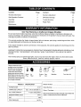
PRODUCT
HORSEPOWER:
CRANKCASE
CAPACITY:
FULE TANK CAPACITY:
RESISTOR SPARK PLUG:
GAP
TIRE PRESSURE
Spark
Plug
Air
Filter
Engine
Oil
Gas
Can
Stabilizer
Tow Hitch Kit
Model Number .........................................................
SPECIFICATION
8 H.P.
Serial Number ...........................................................
26oz. SAE 30 ENGINE OIL
Date of Purchase ......................................................
4 Quart (UNLEADED)
Record both serial number and date of purchase and
keep in a safe place for future reference.
(N4C)
.030
24 PSI
2
This symbol points out important safety instructions which, if not followed, could endanger the personal safety and/or property of yourself and others. Read and follow all instructionsin this manual before
attempting to operate your chipper shredder. Failure to comply with these instructionsmay result in personal injury.When you see this symbol--heed its warning.
Your chipper-shredder was built to be operated according to the rules for safe operation in
DANGER:
,_
this manual. As with any type of power equipment, carelessness or error on the part of the operator can result in serious injury. If you violate any of these rules, you may cause serious
injury to yourself or others.
to cause cancer, birth defects or other reproductive harm.
WARNING: The Engine Exhaust from this product contains chemicals known to the State of California
1. GENERAL
OPERATION
Read this owner's guide carefully in its entirety before
attempting to assemble this machine. Read,
understand, and follow all instructions on the machine
and in the manual(s) before operation. Be completely
familiar with the controls and the proper use of the
machine before operating it. Keep this manual in a
safe place for future and regular reference and for
ordering replacement parts.
Your chipper-shredder is a powerful tool, not a
plaything. Therefore, exercise extreme caution at all
times. Your unit has been designed to perform two
jobs; to chip and shred vegetation found in a normal
yard. Do not use it for any other purpose.
Never allow children under age 16 to operate the unit.
Children 16 years and older should only operate the
unit under close parental supervision. Only
responsible individuals who are familiar with these
rules of safe operation should be allowed to use your
unit.
Keep the area of operation clear of all persons,
particularly small children and pets. Stop the engine
when they are in the vicinity of the unit. Keep work
area clean and clear of branches or obstacles which
could cause you to stumble or fall.
When feeding material into this equipment, be
extremely careful that pieces of metal, rocks, bottles,
cans or other foreign objects are not included.
Personal injury or damage to the machine could result.
Always wear safety glasses or safety goggles, during
operation and while performing an adjustment or
repair, to protect eyes from foreign objects that may be
thrown from the machine.
Wear sturdy, rough-soled work shoes and close fitting
slacks and shirt. Shirt and slacks that cover the arms
and legs and steel-toed shoes are recommended. Do
not wear loose fitting clothes or jewelry and secure hair
so it is above shoulder length. They can be caught in
moving parts. Never operate a unit in bare feet,
sandals or sneakers. Wear gloves when feeding
material in the chipper chute or shredder hopper.
e
m
•
o
e
®
e
Never place your hands, feet, or any part of your body
into the shredder hopper, chipper chute, discharge
opening, or near any moving part while the engine is
running. Keep clear of the discharge opening at all
times. If it becomes necessary to push material into
the chipper chute or shredder hopper, use a small
diameter stick, NOT YOUR HANDS.
If it is necessary for any reason to unclog the feed
intake or discharge openings or to inspect or repair any
part of the machine where a moving part can come in
contact with your body or clothing, stop the machine,
allow it to cool, disconnect the spark plug wire from the
spark plug and move it away from the spark plug
before attempting to unclog, inspect or repair.
Do not operate unit while under the influence of alcohol
or drugs.
The machine should only be operated on a level
surface. Never operate your unit on a slippery, wet,
muddy or icy surface. Keep your work area clean and
clear of branches or obstacles which could cause you
to stumble and fall. Do not overreach. Maintaining
proper footing and balance is essential to preventing
accidents.
Do not allow an accumulation of processed material to
build up in the discharge area as this will prevent
proper discharge and can result in kick-back from the
chipper chute.
Keep your face and body back from chipper chute to
avoid accidental bounce back of any material.
Do not transport machine while engine is running.
If the cutting mechanism strikes a foreign object or if
your machine should start making an unusual noise or
vibration, immediately stop the engine and allow the
machine to come to a complete stop. Disconnect the
spark plug wire and move it away from the spark plug.
Take the following steps.
a. Inspect fordamage.
b. Repair or replace any damaged parts.
c. Check for any loose parts and tighten to assure
continued safe operation.
Never attempt to attach or remove catcher bag when
engine is running. Shut the engine off and wait for the
impeller to come to a complete stop. The impeller
continues to rotate for a few seconds after the engine
is shut off. Never place any part of the body in the
impeller area until you are sure the impeller has
stopped rotating.
Muffler and engine become hot and can cause a burn.
Do not touch.
e
b.
Replace gasoline cap securely and wipe off any
spilled gasoline before starting the engine as it
may cause a fire or explosion.
c. Extinguish all cigarettes, cigars, pipes and other
sources of ignition.
d. Never refuel unit indoors because flammable
vapors will accumulate in the area.
e. Never store the machine or fuel container inside
where there is an open flame or spark such as a
gas hot water heater, space heater, clothes dryer
or furnace.
Never run your machine in an enclosed area as the
exhaust from the engine contains carbon monoxide,
which is an odorless, tasteless and deadly poisonous
gas.
To reduce fire hazard, keep engine and muffler free of
leaves, grass, and other debris build-up. Clean up fuel
and oil spillage. Allow unit to cool at least 5 minutes
before storing.
Before cleaning, repairing, or inspecting, make certain
the impeller and all moving parts have stopped.
Disconnect the spark plug wire and keep wire away
from spark plug to prevent accidental starting. Do not
use flammable solutions to clean air filter.
Check the blade and engine mounting screws at
frequent intervals for proper tightness. Also visually
inspect blades for wear and/or damage (e.g., bent,
cracked). Replace with blades which meet original
equipment specifications.
Keep all nuts, bolts, and screws tight to be sure the
equipment is in safe working condition.
Never tamper with safety devices. Check their proper
operation regularly.
After striking a foreign object, immediately stop the
engine, disconnect the spark plug wire from the spark
plug, and thoroughly inspect the unit for any damage.
Repair damage before starting and operating unit.
Do not alter or tamper with the engine's governor
setting. The governor controls the maximum safe
operating speed of the engine. Over-speeding the
engine is dangerous and will cause damage to the
engine and to other moving parts of the machine.
Do not allow leaves or other debris to build-up on
engine's muffler. The debris could ignite and cause a
fire.
Do not attempt to shred or chip material larger than
specified in this manual. Personal injury or damage to
the machine could result.
Do not operate engine if air cleaner or cover over
carburetor air-intake is removed, except for
adjustment. Removal of such parts could create a fire
hazard.
Only use accessories approved for this machine by the
manufacturer. Read, understand, and follow all
instructions provided with the approved accessory.
If situations occur which are not covered by this
manual, use care and good judgment. Contact your
dealer for assistance.
Keep discharge chute deflector, chipper chute door,
and all other guards and safety devices in place and
operating properly.
Only operate unit in good daylight. Do not operate unit
at night or in dark areas where your vision may be
impaired.
2. CHILDREN
Tragic accidents can occur if the operator is not alert to the
presence of small children. Children are often attracted to
the chipper-shredder and the chipping and shredding
activity. Never assume that children will remain where you
last saw them.
•
•
•
Keep children out of the work area and under the
watchful eye of a responsible adult other than the
operator.
Be alert and turn the unit off if a child enters the area.
Never allow children under the age of 16 to operate the
chipper-shredder.
4. YOUR RESPONSIBILITY
3. SERVICE
•
Restrict the use of this power machine to
persons who read, understand and follow the
warnings and instructions in this manual and on
the machine.
Use extreme care in handling gasoline and other fuels.
They are extremely flammable and the vapors are
explosive.
a. Store fuel and oil in approved containers, away
from heat and open flame, and out of the reach of
children. Check and add fuel before starting the
engine. Never remove gas cap or add fuel while
the engine is running. Allow engine to cool at
least two minutes before refueling.
SAVETHESEINSTRUCTIONS
FOR FUTUREREFERENCE.
This unit is equipped with an internal combustion engine and should not be used on or near any unimproved forestcovered, brush-covered or grass-covered land unless the engine's exhaust system is equipped with a spark arrester
meeting applicable local or state laws (if any). If a spark arrester is used, it should be maintained in effective working
order by the operator.
In the State of California the above is required by law (Section 4442 of the California Public Resources Code). Other
states may have similar laws. Federal laws apply on federal lands. A spark arrester for the muffler is available through
your nearest Sears Authorized Service Center (See the REPAIR PARTS section of this manual.)
4
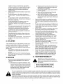
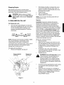
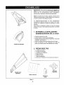
IMPORTANT: This unit is shipped without gasoline
or oil in the engine. After assembly, see
OPERATION section of this manual for proper fuel
and engine oil fill-up.
\
\
NOTE: To determine right and left hand sides of your
chipper-shredder, stand behind the unit with the
engine farthest away from you.
\
Your chipper-shredder has been completely assembled
at the factory, except for the hopper assembly, chipper
chute, discharge chute and the catcher bag.
These parts are shipped loose in the carton. A pair of
safety glasses and a bottle of oil are also included in
the carton.
Hopper
1. REMOVE CHIPPER-SHREDDER
FROM CARTON
®
o
o
Q
4)
Cut the corners of the carton.
Remove all packing inserts.
Remove all loose parts including owner's
manual. See figure 1.
Roll chipper-shredder out of the carton.
Make certain all parts and literature have been
removed before the carton is discarded.
2. LOOSE PARTS
Discharge Chute
a. Hopper Assembly
b. Discharge Chute
c. Chipper Chute
d. Catcher Bag
e. Bottleof Oil
f. Safety Glasses
g. Owner's Manual (not shown in figure 1)
Chipper Chute
Safety
Glasses
Catcher
Figure 1
Bag
Bottle
of Oil
3. TOOLS REQUIRED
1.
2.
3.
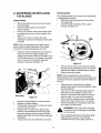
Place second spacer over hex bolt inside the
other part of the hinge. Secure with hex lock nut.
Tighten securely.
Secure both sides of discharge chute to housing
using wing knobs that you earlier removed.
Tighten wing knobs.
1/2" or Adjustable Wrenches
7/16" or Adjustable Wrenches
Funnel
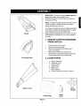
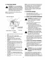
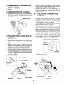
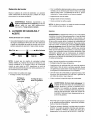
4. DISCONNECTING
SPARK PLUG
6. A'n'ACHING
Disconnect the spark plug wire and move it
away from the spark plug before assembling the
chipper-shredder. See figure 2.
r_
/Spark
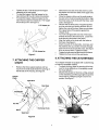
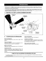
Remove the 8-3/8" long hex bolt and the hex nut
from the bottom of the inlet guide opening.
Place the hopper assembly on the ground and
hold it in the position shown in step 1 in figure 4.
Holding the hopper, push hopper pivot door
down inside the hopper. See figure 4.
Slide the hopper assembly towards the chippershredder housing so that the upper guide on the
hopper assembly slides under the stop washer
on each side of the inlet guide. See figure 4.
Align the two holes (one on each side) of the
lower hopper with the two holes (one on each
side) of the inlet guide.
Insert the hex bolt (that you earlier removed)
from the left through the hole on the hopper and
the inlet guide. Insert the hex nut onto the bolt
from the other side. See figure 4 inset.
Plug Wire
Figure 2
5. A'I-rACHING
HOPPER ASSEMBLY
DISCHARGE CHUTE
Remove the wing knobs from each side of the
discharge opening on the chipper-shredder. See
figure 3.
Using two 7/16" wrenches, remove hex lock
nut, two spacers, and the hex bolt from top of
the housing assembly. For easy assembly, do
not remove the second spacer from the hex bolt.
Place the discharge chute in position on the
discharge opening. Insert hex bolt and spacer
through hinge on discharge chute and housing
(spacer fits inside of hinge). See figure 3 inset.
Inlet Guide Opening
Hopper Pivot Door
Hopper
Hex Nut
\
J
Hex Bolt
J
Hinge
Stop
Knob
Discharge
Chute
Knob
Inlet Guide
Figure 3
Hopper
Figure 4
6
Hex
Nut
t
o
Q
Tighten the bolt. This will secure the hopper
assembly to the inlet guide.
To raise the hopper, hold the hopper by the
hand-hold and lift it up till it clicks into position.
To Iowerthe hopper, hold the hopper by the
hand-hold and pull the release bar. The hopper
should drop down. See figure 5.
Remove the two sets of hex bolt, lock nut, and
flat washer from the two holes on the upper end
of the brace.
1. Lift hopper up
, /
o
o
2. Pull release bar
Q
®
Figure 5
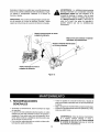
7. ATTACHING
CHUTE
THE CHIPPER
Place the chipper chute over the weld studs so
the slot on the chute is towards the bottom. Align
the three holes on the chute with the three weld
studs. See figure 6.
Secure with the three pairs of cupped washers
and hex nuts that you earlier removed. Do not
tighten the nuts at this time. Make sure to place
the cupped side of the washer against the
chipper chute.
Your unit is shipped with one end of the brace
already secured to the lower frame. Loosen the
bolts securing the brace to the frame.
Align the holes on the chute with the holes on
the brace. See figure 6.
Insert one each of the hex bolts, lock nuts, and
flat washers (that you earlier removed) through
each hole in the chute and the brace. See figure
6 for the correct order. Tighten the bolts.
Tighten the bolts securing the brace to the frame.
Tighten the three nuts on the weld studs.
8. ATTACHING
THE CATCHER
BAG
Your chipper-shredder is equipped with a catcher bag
to catch the shredded material.
Remove the three cupped washers and hex
nuts from the weld studs beside the opening on
the left side of the housing. See figure 6.
•
To attach the bag, place the opening of the bag
over the chute deflector so it completely covers
the chute deflector.
•
Depress the plunger on the draw- string, and pull
on the drawstring until the bag is tight around the
chute opening. Release plunger to lock it into
position. See figure 7.
Weld Stud
Hex Nut
Plunger
Discharge Chute
Catcher
Brace
Weld Stud
Figure 6
Figure 7
Read this owner's manual and safety rules before operating your chipper-shredder. Compare the illustrations
with your chipper-shredder to familiarize yourself with the location of various controls and adjustments. Save
this manual for future reference.
The operation of any chipper-shredder can result in foreign objects being thrown into the eyes, which can result
in severe eye damage. Always wear safety glasses provided with the chipper-shredder or eye shields before
chipping or shredding, or while performing any adjustments or repairs.
1. KNOW YOUR CHIPPER-SHREDDER
?per Assembly
Chipper
Chute
q',\
R:lreaSe
!
C
Starter Handle
2. OPERATING
CONTROLS
be fed into the impeller for chipping and shredding.
Lower the hopper to collect raked material for
shredding.
Release Bar
Throttle Control
Used to release the hopper when raising or lowering.
See figure 8.
Regulates speed of the engine. See figure 8.
Choke Lever
Chipper Chute
Used to enrich the fuel mixture in the carburetor
when starting a cold engine. See figure 8.
Allows bulky vegetation like stalks or heavy branches
upto 3" diameter to be fed into the impeller for
chipping and shredding. See figure 8.
Starter
Handle
Catcher Bag (Not Shown)
Used to manually start the engine. See figure 8.
Used to collect the shredded material.
Hopper Assembly
Allows leaves and small branches upto 1" diameter to
MEETS ANSI SAFETY STANDARDS
Sears chipper-shredders conform to the safety standard B 71.6 -1990 of the American National Standards Institute.
8
Stopping
Engine
Move throttle control lever to STOP position.
Disconnect spark plug wire and move away from
spark plug to prevent accidental starting.
o
WARNING:
Before using your chippershredder, again refer to the safety rules on
page 3 and 4 of this manual. Always be
careful.
Oil (Packed with unit)
Only use high quality detergent oil rated with
API service classification SF, SG or SH. Select
the oil's viscosity grade according to your
expected operating temperature. Follow the
chart below.
32 °F_
5W30
[
Warmer
SAE 30
NOTE: Although multi-viscosity oils (5W30, 10W30,
etc.) improve starting in cold weather, these
multiviscosity oils will result in increased oil
consumption when used above 32°F. Check the oil
level more frequently to avoid possible engine
damage from running low on oil.
Fill engine with oil as follows.
•
Remove oil fill dipstick. See figure 9
Remove dipstick
and fill oil
NOTE: Do not overfill. Oil bottle packed with unit
contains 26 oz. of oil.
Gasoline
3. GAS AND OIL FILL-UP
Colder _
o
With chipper-shredder on level ground, use a
funnel to fill engine with oil to FULL mark on
dipstick. Capacity is approximately 26 ounces.
Be careful not to overfill.
Check oil level.
Add oil if necessary.
Replace dipstick and tighten.
Remove cap
and fill gas
WARNING: Experience indicates that alcohol
blended fuels (called gasohol or using ethanol or
methanol) can attract moisture which leads to
separation and formation of acids during storage.
Acidic gas can damage the fuel system of an engine
while in storage. To avoid engine problems, the fuel
system should be emptied before storage for 30
days or longer. Drain the gas tank, start the engine
and let it run until the fuel lines and carburetor are
empty. Use fresh fuel next season. See STORAGE
instructions for additional information. Never use
engine or carburetor cleaner products in the fuel tank
or permanent damage may occur.
Fill gas tank with gas as follows.
•
Remove fuel cap.
•
Make sure the container (from which you will
pour the gasoline) is clean and free from rust or
foreign particles. Never use gasoline that may
be stale from long periods of storage in the
container.
•
Fill fuel tank with clean, fresh, lead-free
automotive gasoline. DO NOT use Ethyl or high
octane gasoline. See figure 9.
.
Replace fuel cap.
WARNING:
Do not fill closer than 1/2 inch
of top of fuel tank to prevent spills and to
allow for fuel expansion. If gasoline is
accidently spilled, move chipper-shredder
away from area of spill. Avoid creating any
source of ignition until gasoline vapors have
disappeared.
Check the fuel level periodically to avoid running
out of gasoline while operating the chippershredder.
If the unit runs out of gas as it is shredding or
chipping, it may be necessary to unclog the unit
before it can be restarted. Refer to Removing
the Flail Screen in SERVICE AND
ADJUSTMENT section.
Figure 9
4. STARTING
WARNING:
ENGINE
NOTE: A noise will be heard when finding the start of
the compression cycle. This noise is caused by the
flails and fingers which are part of the shredding
mechanism falling into place, and should be
expected. In addition, the flails and fingers will be
noisy after the engine is started, until the impeller
reaches full speed.
Be sure no one other than
the operator is standing near the chippershredder while starting or operating. Do not
operate this chipper-shredder unless the
chute deflector has been properly installed
and is secured with the hand knobs.
5. STOPPING
NOTE: To prevent the unit from sliding, place your
foot firmly against the tire.
ENGINE
Move starter switch to OFF position.
Disconnect spark plug wire and move away from
spark plug to prevent accidental starting.
6. USING YOUR CHIPPER-SHREDDER
1. Attach spark pl Jg wire
WARNING: Do not attempt to shred or
chip any material other than vegetation
found in a normal yard (i.e., branches,
leaves, twigs, etc.).
\
The chipper-shredder is designed for three
different methods of operation.
a. Leaves and small branches up to 1"
diameter (maximum) can be fed into the
hopper assembly when it is in the raised or
lowered position. See figure 12.
b. Bulky material, such as stalks or heavy
branches, up to 3" in diameter should be
fed into the chipper chute. See figure 12.
Place Throttle
in Fast Position
\
_4.
Pull rope
3. Move choke to "on" position
WARNING:
Do not put material larger
than is specified into the hopper, and/or into
the chipper chute. Personal injury or
damage to the machine could result.
Figure 11
@
@
@
Attach spark plug wire and rubber boot to spark
plug.
Move starter switch to "ON" position.
Move choke lever to CHOKE position (in the
direction of the arrow).
If restarting a warm engine after a short
shutdown, move choke lever to "No Choke"
position.
Grasp starter handle and pull rope out slowly
until engine reaches start of compression cycle
(rope will pull slightly harder at this point). Let
the rope rewind slowly.
Pull rope with a rapid full arm stroke. Let rope
return to starter slowly.
When engine starts, move choke lever to half
choke position until engine runs smoothly and
then to No Choke position.
If engine fails to start after three pulls, move
choke lever to No Choke position and pull starter
rope again.
If engine fires, but does not continue to run,
move choke lever to Full Choke position and pull
rope again.
Move choke lever to OFF position as engine
warms up.
If it becomes necessary to push material into the
chipper-shredder, use a small diameter stick -NOT YOUR HANDS. The stick should be small
enough that it will be ground up if it gets into the
impeller assembly.
7. LOWER THE HOPPER
ASSEMBLY
To lower the hopper assembly, use one hand to
grasp the hand-hold at the top of the hopper
assembly and lift slightly. See figure 5.
Pull up on the release bar, and lower the hopper
assembly to the ground. Release the bar. See
figure 5.
WARNING:
Never remove chute deflector
till the unit has completely stopped. Never
shut off the engine until all chipping is
completed.
For best performance, it is important to keep the
shredding blade and the chipper blades sharp. If the
composition of the material being discharged
changes (becomes stringy, etc.) or if the rate at which
the material is discharged slows down considerably, it
10
is likelythattheshreddingbladeand/orchipper
bladesaredullandneedtobesharpened
or
replaced.RefertoServiceandAdjustments
section.
IMPORTANT:
Thereisa flailscreenlocatedinside
thehousinginthedischarge
area.Iftheflailscreen
becomesclogged,removeandcleanas instructed
in
theServiceandAdjustments
section.
WARNING:Thechipper-shredder
discharges
materials
withconsiderable
velocity.Keepaway from the area around the
discharge chute. Always stop the engine
and disconnect spark plug wire when
removing or attaching the bag, changing
containers, or removing the shredded
material. Wear safety glasses and gloves
whenever using your chipper-shredder.
Shred material upto 1 inch in diameter
/
Chip material upto 3 inches
in diameter
Catch shredded material
in catcher bag
Lower the hopper to collect
raked material for shredding
Figure 12
1. GENERAL
o
o
RECOMMENDATIONS
Always observe safety rules when performing
any maintenance.
The warranty on this snow thrower does not
cover items that have been subjected to operator
abuse or negligence. To receive full value from
the warranty, operator must maintain the chippershredder as instructed in this manual.
Some adjustments will need to be made
periodically to maintain your unit properly.
11
All adjustments in the Service and Adjustments
section of this manual should be checked at least
once each season.
Follow the maintenance schedule given below.
Periodically check all fasteners and make sure
these are tight.
WARNING:
Always stop the engine and
disconnect the spark plug wire before
performing any maintenance or
adjustments. Never remove discharge
chute till the engine has completely stopped.
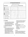
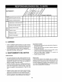
CUSTOMER
MAINTENANCE
_
_"
RESPONSIBILITIES
_
p
p
_o" SERVICE
DATES
S
Oil pivot points
g
o.
Clean shredder
Check engine oil
u.I
Z
m
Change
engine oil
Service
air cleaner
Z
ILl
Clean engine
Reset spark plug
Clean muffler
checking oil level. With engine on level ground,
the oil must be to FULL mark on dipstick.
Change engine oil after the first five hours of
operation, and every twenty-five hours
thereafter.
2. CLEANING
Clean the chipper-shredder by running water
from a hose through the hopper assembly and
chipper chute with the engine running. Allow
the chipper-shredder to dry thoroughly.
Wash the bag periodically with water. Allow to
dry thoroughly in the shade. Do not use heat.
To Drain Oil
Drain oil while engine is warm. Follow the
instructions given below.
•
Remove oil drain plug. Catch oil in a suitable
container.
•
When engine is drained of all oil, replace drain
plug securely.
•
Refill with fresh oil. Refer to GAS AND OIL
FILL-UP section.
•
Replace dipstick.
3. ENGINE MAINTENANCE
Engine Oil
•
•
•
Only use high quality detergent oil rated with
API service classification SF, SG or SH. Select
the oil's viscosity grade according to your
expected operating temperature. Refer to
page 9 of this manual for viscosity chart.
The four-cycle engine of your chippershredder will normally consume some oil.
Therefore, check engine oil level regularly
approximately every five hours of operation
and before each usage.
Stop engine and wait several minutes before
Air Cleaner
The air cleaner prevents damaging dirt, dust, etc.,
from entering the carburetor and being forced into
the engine and is important to engine life and
performance. The air cleaner consists of a precleaner or foam filter, and a paper filter. Never run
12
theenginewithoutaircleanercompletely
assembled.
ToServiceAir Cleaner:
1.
2.
3.
•
Service pre-cleaner after every 25 hours of use,
or at least once a season.
Service filter every 100 hours of use, or at least
once a season.
Service pre-cleaner and filter more often under
dusty conditions.
Remove wing nut and cover.
Slide pre-cleaner off filter. Clean the inside of
base and cover thoroughly.
L
Fins
Figure 14
Yearly or every 25 hours, whichever occurs first,
remove the blower housing and clean the areas
shown in figure 14 to avoid overspeeding,
overheating and engine damage. Clean more
often if necessary.
NUT
PAPER
FOAMFILTER(IF SO EQUIPPED)
NOTE: Cleaning with a forceful spray of water is not
recommended as water could contaminate the fuel
Figure 13
system.
Clean pre-cleaner as follows:
a. Wash in water and detergent solution, and
squeeze (do not twist) until all dirt is
removed.
b. Rinse thoroughly in clear water.
c. Wrap in a clean cloth and squeeze (do not
twist) until completely dry, or allow to air dry.
d. Saturate with engine oil and squeeze (don't
twist) to distribute oil and remove excess oil.
nearby areas Temperature
WARNING:
may exceed 150
of muffler
° F(65°C).
and
Avoid these areas.
Spark Plug
Clean the spark plug and reset the gap to .030"
at least once a season or every 50 hours of
operation. See figure 15. Spark plug
replacement is recommended at the start of
each season. Refer to engine parts list for
correct spark plug type.
NOTE: If the pre-cleaner is torn or damaged in any
way, replace it.
•
•
•
°
If necessary, replace paper filter (do not attempt
to clean). Install new filter on base.
Slide pre-cleaner over filter.
Install cover and wing nut.
Tighten wing nut securely.
.030" Feeler Gauge
Clean Engine
•
Clean engine periodically. Remove dirt and
debris with a cloth or brush.
°
Frequently remove grass clippings, dirt and
debris from cooling fins, air intake screen and
levers and linkage. This will help ensure
adequate cooling and correct engine speed.
See figure 14
zrk Plug
Figure 15
NOTE: Do not sandblast spark plug. Spark plug
should be cleaned by scraping or wire brushing and
washing with a commercial solvent.
13
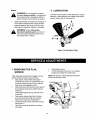
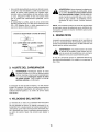
4. LUBRICATION
Muffler
WARNING: Do not operate the chippershredder without a muffler, or tamper with
the exhaust system. Damaged mufflers or
spark arresters could create a fire hazard.
Lubricate the pivot points on the release bar, hopper
assembly, chute deflector and chipper chute once a
season using a light oil. See figure 16
Inspect periodically, and replace if necessary. If
your engine is equipped with a spark arrester
screen assembly, remove every 50 hours for
cleaning and inspection. Replace if damaged.
WARNING: Always stop engine,
disconnect spark plug wire, and move it
away from spark plug before performing
any adjustments or repairs.
Figure 16: Lubrication Chart
1. REMOVING
SCREEN
THE FLAIL
•
•
•
Reinstall the screen.
•
Put the discharge chute back to its original
position and tighten the hand knobs.
NOTE: Be certain to reassemble the flail screen
with the curved side down.
If the discharge area becomes clogged, remove
the flail screen and clean area as follows.
•
Stop engine, make certain the chippershredder has come to a complete stop and
disconnect spark plug wire from the spark
plug before unclogging the chute.
•
Remove the two hand knobs on each side of
°
•
Hairpin
Clips,
Clevis
Pins
the discharge chute (also called the chute
deflector).
Lift the discharge chute up, and keep it out
of the way.
Remove two hairpin clips from the clevis
pins which extend through the housing.
Remove the clevis pins. See figure 17.
Pull the flail screen from inside the housing.
See figure 17.
Clean the screen by scraping or washing
with water.
Flail
Screen
Nuts,
Washers
c
Hand
Knobs
Figure 17
14
2. SHARPENING OR REPLACING
THE BLADES
Shredding Blade
The shredding blade may be removed for sharpening
or replacement as follows.
•
Disconnect spark plug wire and move it away
from spark plug.
•
Lower the hopper assembly. Block up the
housing. See figure 19.
Chipper Blades
Disconnect spark plug wire and move it away
from spark plug.
Remove the flail screen as instructed in
previous section.
Using a 1/2" wrench, remove the chipper chute
by removing three hex nuts and washers. See
figure 17.
Using a 7/16" wrench, remove the brace
(holding the chute to the frame) by removing the
hex bolts.
Allen
Screws
f
NOTE: When re-assembling, the cupped washer
goes on the slot toward the bottom of the chipper
chute with the cupped side against the chute.
Pipe
Rotate the impeller assembly by hand until you
locate one of the two chipper blades in the
chipper chute opening. Remove the blade, using
a 3/16" allen wrench on the outside of the blade
and 1/2" wrench on the impeller assembly
(inside the housing). See figure 18.
Blade
Wrench
Figure 19
•
Remove the six hex lock nuts and lock washers
•
from the housing weld bolts using a 1/2" wrench.
Separate the chipper-shredder into two halves.
Remove the back-up plate.
NOTE: When reassembling, make certain the
embossed tab faces inward towards the impeller, and
opening on the back-up plate is toward the bottom of
the unit.
Remove the two hand knobs and cupped
washers which secure the chute deflector. Raise
the chute deflector.
Sharp Edge
o
Insert a 1/2" or 3/4" diameter pipe through the
flail screen into the impeller to keep it from
turning, or remove the flail screen and insert a
piece of wood (2 x 4) into the chute opening.
Remove the two outside screws on the blade,
using a 3/16" allen wrench and a 1/2" wrench.
Remove the blade by removing the center bolt,
lock washer and flat washer.
Figure 18
Remove the other blade in the same manner.
Replace or sharpen blades.
If sharpening, make certain to remove an equal
amount from each blade.
Reassemble in reverse order. Make certain
_
blades are reassembled with the sharp edge
facing the direction shown in figure 18 (sharp
edge is assembled toward the slotted opening at
the bottom).
Torque bolts and nuts to 250-350 inch-pounds.
the
blade to avoid
the removing
weld bolts
WARNING:
Use contacting
caution when
on the housing.
When sharpening the blade, follow the original
angle of grind as a guide. It is extremely
important that each cutting edge receives an
15
equalamountofgrindingto preventan
unbalanced
blade.
Anunbalanced
bladewillcauseexcessive
vibrationwhenrotatingathighspeedsandmay
causedamage
totheunit.Thebladecanbetested
forbalance
bybalancing
itona roundshaft
screwdriver
ornail.Removemetalfromtheheavy
sideuntilitisbalanced
evenly.
Seefigure20.
Whenreassembling
theblade,tightencenter
bolttobetween550and650inch-pounds
and
thetwoouterboltstobetween250and350inchpounds,or lackingtorquewrench,tighten
securely.
1. Insert screw driver through hole
d./
2. Blade should be parallel to ground
Screv_
Driver_
Bla_d_e
/
Ground
Figure 20
3. ADJUSTING
CARBURETOR
WARNING: If any adjustments are made to
the engine while the engine is running (e.g.
carburetor), keep clear of all moving parts.
Be careful of heated surfaces and muffler.
The carburetor has been pre-set at the factory and
should not require adjustment. However, if your
engine does not operate properly due to suspected
carburetor problems, take your chipper-shredder to
your nearest SEARS service center.
4. ENGINE SPEED
The engine speed on your chipper-shredder has
been set at the factory. Do not attempt to increase
engine speed or it may result in personal injury. If you
believe the engine is running too fast or too slow, take
your chipper-shredder to the nearest SEARS service
center for repair and adjustment.
16
5. TIRES
Recommended operating tire pressure is 24 p.s.i.
(sidewall of tire may give tire manufacturers
recommended pressure). Equal tire pressure should
be maintained on both tires.
_
beads
may cause
tire/rim assembly
to burst
with
ARNING:
Excessive
pressure when
seating
force sufficient to cause serious injury.
Prepare your chipper-shredder for storage at the end
of the season or if the unit will not be used for 30 days
or more.
WARNING:Neverstoremachinewithfuel
inthefueltankinsideofbuildingwhere
fumesmayreachan open flame or spark,
carburetor.
Do not drain the gas tank and carburetor if using
fuel stabilizer. Drain all the oil from the
crankcase (this should be done after the engine
has been operated and is still warm) and refill
the crankcase with fresh oil.
If you have drained the fuel tank, protect the
inside of the engine as follows.
Remove spark plug, pour approximately 1/2
ounce (approximately one tablespoon) of engine
oil into cylinder and crank slowly to distribute oil.
Replace spark plug.
or where ignition sources are present such
as hot water and space heaters, furnaces,
clothes dryers, stoves, electric motors, etc.
A yearly check-up by your local Sears service center
is a good way to make certain your chipper-shredder
will provide maximum performance for the next
season.
1. CHIPPER-SHREDDER
3. OTHER
Clean the chipper-shredder thoroughly.
Wipe unit with an oiled rag to prevent rust (use a
light oil or silicone).
Do not store gasoline from one season to
another.
Replace your gasoline can if your can starts to
rust. Rust and/or dirt in your gasoline will cause
problems. Store unit in a clean, dry area. Do not
store next to corrosive materials, such as
fertilizer.
2. ENGINE
IMPORTANT: It is important to prevent gum deposits
from forming in essential fuel system parts such as
carburetor, fuel filter, fuel hose, or tank during
storage. Also, experience indicates that alcohol
blended fuels (called gasohol or using ethanol or
methanol) can attract moisture which leads to
separation and formation of acids during storage.
Acidic gas can damage the fuel system of an engine
while in storage.
NOTE: If storing in an unventilated or metal storage
shed, be certain to rustproof the equipment by coating
with a light off or sificone.
Drain the fuel tank.
Start the engine and let it run until the fuel lines
and carburetor are empty.
Drain carburetor by pressing upward on bowl
drain which is located below the carburetor.
Never use engine or carburetor cleaner
products in the fuel tank or permanent damage
may occur.
Use fresh fuel next season.
NOTE: Fuel stabilizer is an acceptable alternative in
minimizing the formation of fuel gum deposits during
storage.
Add stabilizer to gasoline in fuel tank or storage
container.
Always follow the mix ratio found on stabilizer
container.
Run engine at least 10 minutes after adding
stabilizer to allow the stabilizer to reach the
17
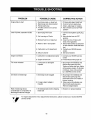
PROBLEM
Engine fails to start
POSSIBLE
1.
2.
3.
4.
CAUSE
Fuel tank empty, or stale fuel
Spark plug wire disconnected
Faulty spark plug
Throttle control not in correct
position
Loss of power; operation erratic
1. Spark plug wire loose
2. Unit running on Choke
3. Blocked fuel line or stale fuel
4. Water or dirt in fuel system
5. Carburetor out of adjustment
6. Dirty air cleaner
Engine overheats
1. Carburetor not adjusted properly
2. Engine oil level low
CORRECTIVE
1.
2.
3.
4.
ACTION
Fill tank with clean, fresh fuel
Connect wire to spark plug.
Clean, adjust gap or replace.
Move throttle control to FAST
position
1. Connect and tighten spark plug
wire
2. Move choke lever to OFF
position
3. Clean fuel line; fill tank with
clean, fresh gasoline.
4. Disconnect fuel line at carburetor
to drain fuel tank. Refill with fresh
fuel.
5. Contact your SEARS service
center.
6. Service air cleaner.
1. Contact your SEARS service
center
2. Fill crankcase with proper oil
Too much vibration
1. Loose parts or damaged
impeller
1. Stop engine immediately and
disconnect spark plug wire.
Tighten all bolts and nuts. Make
all necessary repairs. If vibration
continues, have unit serviced
by a SEARS service center.
Unit does not discharge
1. Discharge chute clogged
1. Stop engine immediately and
disconnect spark plug wire.
clean flail screen and inside of
blower housing.
2. Stop engine immediately and
disconnect spark plug wire.
Remove lodged object.
2. Foreign object lodged in
impeller
Rate of discharge slows
considerably or composition of
discharged material changes
1. Shredding blade and/orchipping
blade dull
1. Sharpen or replace blade(s)
For repairs beyond the minor adjustments listed above, please contact your nearest SEARS
service center.
18
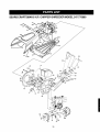
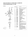
SEARS CRAFTSMAN
8 H.P. CHIPPER=SHREDDER
MODEL 247.775860
16
79 76
8
_o
_
.82
82
85
57
23
28
10
19
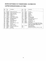
SEARS CRAFTSMAN
KEY
NO.
8 H.P. CHIPPER-SHREDDER
KEY
NO.
DESCRIPTION
PART NO.
MODEL 247.775860
PART NO.
DESCRIPTION
770-0549M
Owner's Manual
39
710-3008
Hex Bolt 5/16-18 x .75" (Gr. 5)
1.
742-0571
Shredder Blade
4O
710-0442
Hex Bolt 5/16-18 x 1.5"
2.
710-1254
Hex Patch Bolt 3/8-24 x 2.25" Lg.
(Gr.8)
41
681-0004A
Flail Housing Ass'y. -- Outer
42
681-0117
Flail Housing Ass'y. -- Inner
3
143,978005
Engine
43
710-0106
Hex Scr. 1/4-20 x .625 (Gr, 2)
4
736-0217
Lock Washer 3/8" I.D.
45
747-0531A
Release Bar
5
736-0247
Flat Washer .406" I.D. x 1.25" O.D.
46
732-0546
Torsion Spring
6
719-0329
Flail Blade
47
712-0429
Elastic Lock Nut 5/16-18 Thd.
8
711-0833B
Clevis Pin .496" dia.
48
710-0607
10
715-0249
Spring Roll Pin 1.12" Lg.
Hex Washer Hd. Self-Tapping
Scr. 5/16-18 x .50" Lg.
12
681-0030
Impeller Ass'y. Comp,
49
11480
Stop Washer
l&
781-0490
Chipper Blade
5O
710-0258
Hex Bolt 1/4-20 x .625
14.
710-1054
Flat Hd. Scr. 5/16-24 x .75" Lg.
51
710-0542
Hex Bolt 5/16-18 x 8.38" Lg.
15.
712-0411
Hex Top Lock Nut 5/16-24 (Gr.5)
52
781-0715
Shredder Plate
16.
736-0119
Lock Washer 5/16" I.D.
53
681-0111
Inlet Guide Ass'y.
17.
710-0825
Hex Bolt 1/4-20 x 3.75" Lg.
54
712-3027
Flanged Lock Nut
L 19.
750-0793
Chute Hinge Spacer 1.66" Lg.
55
728-0175
Pop Rivet
20.
711-0835
Clevis Pin .5" Dia. x 4.62" Lg.
56
731-1899
Chipper Chute
22
712-0291
Hex Ctr. Lock Nut 1/4-20 Thd.
57
735-0249
Shredder Chute Flap
23.
681-0068
Chipper Chute Ass'y.
58
736-0173
Flat Washer .28 I.D. x .74 O.D.
24.
781-0457
Shredder Screen
59
726-0214
Push Cap 5/8" Dia. Rod
25.
714-0149B
Internal Cotter Pin 3/8" dia.
61
736-0366
Flat Washer 1.12 O.D. x
.64 I.D. x .120
26
681-0094
Discharge Chute Ass'y.
62
738-0813
Shredder Axle
27.
712-3010
Hex Nut 5/16-18 Thd. (Gr.5)
63
28.
736-0242
Bell Washer .345" I.D. x .88"
734-1845
734-0210
Wheel Ass'y. Comp.
Tire only
29
720-0170
Hand Knob
65
741-0487
Flange Bearing .632" I.D.
34
736-0170
Spec. Lock Washer 5/16" I.D.
66
734-0255
Air Valve
36
781-0510B
Shredder Frame
75
732-0629
Torsion Spring
37
710-0157
Hex Bolt 5/16-24 x .75" Lg.
76
747-0747
Hopper Door Rod
(Table continued on page 21)
20
SEARS CRAFTSMAN
8 H.P. CHIPPER-SHREDDER
MODEL 247.775860
Table continued from page 20)
KEY
NO.
DESCRIPTION
PART NO.
77
781-0492A
Hopper -- Pivot Door
79
726-0106
Cap Speed Nut 1/4" Rod
8O
781-0692
Upper Hopper
81
781-0693
Lower Hopper
82
712-0107
Lock Nut 1/4"- 20
83
781-0698
Hopper Lockout Bracket
84
749-1004
Chipper Chute Support
85
781-0633
Flap Strip
86
710-0286
Screw 1/4"- 20.5in.
21
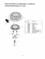
SEARS CRAFTSMAN
8 H.P. ENGINE MODEL 143.978005
CHIPPER-SHREDDER
FOR
MODEL 247.775860
ooo]
t
80
83 81
_i__'_ 292
75 71
342
87
89
70
69
101
47 •
171
169,
/
25
26
162
/
184,
-1
\
277
276
277A
240
/
245
245A
3700_.[_]-"
250
/
251
416
22
325
_..i't10
>3OO
SEARS CRAFTSMAN
CHIPPER-SHREDDER
Key No.
1
2
4
5
15
15A
15B
16
17
18
19
20
25
26
28
30
35
36
37
38
40
41
42
43
45
47
48
49
5O
60
65
69
70
71
72
75
8O
81
82
83
84
86
87
89
90
Part No.
35385
27652
30969
30699C
30700
650494
33454
29916
651028
34663
35319
36460
650561
30322
36283A
29826
29918
29216
29642
34552
34553
34554
34329A
34330A
34331A
34332
34333
34334
27888
36897
651033
34034
36896
35375
33273A
650128
35262A
35376
35377
28582
35319
31845
30590A
35378
30588A
29193
650833
650832
32589
611O90
8 H.P. ENGINE MODEL 143.978005
FOR
MODEL 247.775860
Description
Key No.
Part No.
Description
RPM Low 1700
RPM High 3450 to 3750
Cylinder (Incl. 2 & 20)
Dowel Pin
Oil Drain Extension
Extension Cap
Governor Rod (Incl. 15A & 15B)
Governor Yoke
Screw, 6-40 x 5/16"
Governor Lever
Governor Lever Clamp
Screw, Torx "1--15,8-32 x 3/8"
Speed Control Spring
Oil Seal
Blower Housing Baffle
Screw, 1/4-20 x 5/8"
Lock Nut, 8-32
Crankshaft
Screw, 10-32 x 3/4"
Lock Washer
Lock Nut, 10-32
Retaining Ring
Piston, Pin, And Ring Set (Std.)
Piston, Pin, And Ring Set (.010" O.S.)
Piston, Pin, And Ring Set (.020" 0.S.)
Piston & Pin Ass'y. (Std.) (Incl. 43)
Piston & Pin Ass'y. (.010" O.S.)(Incl. 43)
Piston & Pin Ass'y. (.020" 0.S.) (Incl. 43)
Ring Set (Std.)
Ring Set (.010" O.S.)
Ring Set (.020" 0.S.)
Piston Pin Retaining Ring
Connecting Rod Ass'y. (Incl. 47 & 49)
Connecting Rod Bolt
Valve Lifter
Oil Dipper
Camshaft (MCR)
Blower Housing Extension
Screw, 10-24 x 1/2"
Cylinder Cover Gasket
Cylinder Cover (Incl. 71,75 & 80)
Crankshaft Bushing
Oil Drain Plug
Oil Seal
Governor Shaft
Washer
Governor Gear Ass'y. (Incl. 81)
Governor Spool
Retaining Ring
Screw, 1/4-20 x 1-3/16"
Screw, 1/4-20 x 1-11/16"
Flywheel Key
Flywheel
92
93
100
101
102
103
110
119
120
125
650880
650881
35135
610118
650872
651007
35187
36448
36449
27878A
27880A
34035
34036
650691
650690
650694A
650273
33636
33369
650838
27882
35862
27881
32581
27898A
28423
28424
28425
35350
650128
29752
30088A
33263
34707
34667
34677
31342
651029
610973
33878
650821
35882
650378
27915A
28820
27272A
33266
33267
33268
35881
33269A
650513
36250
Lock Washer
Flywheel Nut
Solid State Ignition
Spark Plug Cover
Solid State Mounting Stud
Screw, Torx T-15, 10-24 x 15/16"
Ground Wire
126
127
128
130
130B
135
139
140
149
149A
150
151
169
170
171
172
173
174
178
182
184
185
186
2OO
203
204
206
2O7
209
215
223
224
238
239
240
242
245
245A
25O
251
260
23
Cylinder Head Gasket
Cylinder Head
Exhaust Valve (Std.) (Incl. 151)
Exhaust Valve (1/32" O.S.) (Incl. 151)
Intake Valve (Std.) (Incl. 151)
Intake Valve (1/32" O.S.) (Incl. 151)
Washer
Belleville Washer
Screw, 5/16-18 x 2"
Screw, 5/16-18 x 5/8"
Resistor Spark Plug (RJ-17LM)
Governor Gear Bracket
Screw, 10-24 x 1/2"
Valve Spring Cap
Valve Spring Cap
Valve Spring
Valve Spring Keeper
Breather Gasket
Breather Body
Breather Element
Valve Cover
Breather Tube
Screw, 10-24 x 1/2"
Nut and Lock Washer, 1/4-28
Screw, 1-4-28 x 1"
Carburetor to Intake Pipe Gasket
Intake Pipe
Governor Link
Control Bracket (Inc1.19, 203 & 204)
Compression Spring
Screw, Torx T-10, 5-40 x 7/16"
Terminal
Throttle Link
Screw, 10-32 x 1/2"
Control Knob
Screw, Torx "1"-30,5/16-18 x 1-1/8"
Intake Pipe Gasket
Screw, 10-32 x 1/2"
Air Cleaner Gasket
Air Cleaner Body
Air Cleaner Bracket
Air Cleaner Filter
Air Cleaner Filter
Air Cleaner Cover
Wing Nut, 1/4-20
Blower Housing
SEARS CRAFTSMAN
CHIPPER-SHREDDER
8 H.P. ENGINE MODEL 143.978005
FOR
MODEL 247.775860
Key
No.
Part
No.
Description
Key
No.
Part
No.
Description
261
262
264A
265
275
276
277
277A
278
280
281
282
285
287
290
292
298
300
301
305
650788
29747B
650802
33272B
34185B
31588
650729
651036
36908
36799A
33013
650760
35985B
29752
30962
26460
650665
34186A
36246
35554
Screw, 5/16-18 x 3/4"
Screw, Torx T-40, 5/16-24 x 21/32"
Screw, 1/4-20 x 5/8"
Cylinder Head Cover
Muffler
307
308
310
325
327
339
340
341
342
370C
370J
380
390
400
35499
35540
36205
29443
35392
35880
34259
34258A
30063
35274
35703
632351
590704
36450B
"O"-Ring
Fill Tube Clip
Dipstick
Wire Clip
Starter Plug
Spacer
Fuel Tank Bracket
Fuel Tank Bracket
Screw, Torx T-30, 1/4-20 x 1/2"
Oil Instruction Decal
Throttle Decal
Carburetor (Incl. 184)
Recoil Starter
416
8OO
9OO
34479A
Locking Plate
Screw, 5/16-18 x 3-3/16"
Screw, 5/16-18 x 3-31/32"
Heat Shield Spacer
Heat Shield
Starter Bubble Cover
Screw, 8/32 x 3/8"
Starter Cup
Nut & Lock Washer, 1/4-28
Fuel Line
Fuel Line Clamp
Screw, 1/4-15 x 3/4"
Fuel Tank (Incl. 292 & 301)
Fuel Cap
Oil Fill Tube
24
Gasket Set (Incl. Items Marked PK in Notes)
Incl. part #'s 27272A, 27896A, 27915A, 29673,
33263, 33629, 34698A, 35262A, 36448
Spark Arrester Kit
Replacement Engine.
Replacement SB 758321, order from 71-999
SEARS CRAFTSMAN
CHIPPER-SHREDDER
8 H.P. ENGINE MODEL 143.978005
FOR
MODEL 247.775860
Carburetor
Key
No.
20
Part
No.
Description
632351
Carburetor (Incl. 184 of Engine Parts
List)
Throttle Shaft & Lever Assembly
Throttle Return Spring
Dust Seal Washer
Dust Seal (Throttle)
Throttle Shutter
Shutter Screw
Choke Shaft &Lever Assembly
Choke Return Spring
Dust Seal Washer
1
2
4
5
6
7
10
11
12
13
14
15
16
17
631776A
631970
631184
631183
631778
650508
631812
632043
631184
631183
631753
630735
632164
650417
18
2O
21
22
23
25
27
28
29
30
31
40
630766
632281
63O766
630739
63O740
631867
631024
632019
631 O28
631021
631022
632239
41
42
43
630740
630739
630738
44
47
48
60
27110
630748
631027
632347
25
Dust Seal (Choke)
Choke Shutter
Choke Positioning Spring
Fuel Fitting
Throttle Crack Screw/Idle Speed
Screw
Tension Spring
Idle Mixture Screw
Tension spring
Idle Mixture Screw Washer
Idle Mixture Screw "O"-Ring
Float Bowl
Float Shaft
Float
Float Bowl "O"-Ring
Inlet Needle, Seat & Clip (Incl. 31)
Spring Clip
Main Adj. Screw Ass'y. (Incl. 41 thru
44)
High Speed Mixture Screw "O"-Ring
High Speed Mixture Screw Washer
High Speed Mixture Screw Tension
Spring
Bowl Nut Washer
Welch Plug, Idle Mixture Well
Welch Plug, Atmospheric Vent
Repair Kit (Incl. Items Marked PK in
Notes) Incl. (1) each of Part #'s
27110, 630740, 630748, 631021,
631022, 631024, 631027, 631028,
632239, 632281
SEARS CRAFTSMAN
8 H.P. ENGINE MODEL 143.978005
CHIPPER-SHREDDER
FOR
MODEL 247.775860
-11
//
13
Key
No.
Part
No.
Description
1
2
3
4
5
6
7
8
11
12
13
59O704
590599A
590600
590696
590601
59O697
590698
590699
590700
590705
590535
590701
Recoil Starter
Spring Pin (Incl. 4)
Washer
Retainer
Washer
12
8
q_--2
26
Brake Spring
Starter Dog
Dog Spring
Pulley & Rewind Spring Ass'y
Starter Housing Ass'y
Starter Rope (98" x 9/64" Dia.)
Starter Handle
:orthe repairor replacementpartsyou need
delivereddirectlyto yourhome
Call7 am - 7 pm, 7 days a week
1-800-366
PART
(1-800-366-7278)
Forin-homemajor.brandrepairservice
Call24 hoursa day,7 daysa week
1-8OO-4-REPAIR
(1-800-473-7247)
Forthe locationof a
SearsPartsandRepairCenterin yourarea
Call 24 hours a day,7 daysa week
1-800-488-1222
For information on purchasinga Sears
Maintenance Agreementor to inquire
about an existing Agreement
call 9 am - 5 prn, Monday-Saturday
1-800-827-6655
SEARS
America's
Repair Specialists
mmmmmm
mmmmmm
Manual del Propietario
CRRFTSMRN
8.0 HP
Capacidad
de astillado de 3" de dia.metro
ASTILLADORA-DESMENUZADORA
Modelo No.
247.775860
PRECAUClON:
Antes de operar
este equipo
lea y observe
todas las reglas
e instrucciones
de seguridad
Sears, Roebuck
Impreso en U.S.A.
and Co., Hoffman
Estates, IL 60179, U.S.A.
770-0549M
Contenido
P#,gina
Informaci6n de garantfa
2
Pr_.cticas seguras de operaci6n
3
Ensamblado
5
Operaci6n
8
Garantfa de un afio para la astilladora-desmenuzadora
Contenido
P&gina
Mantenimiento
11
Servicio y Ajuste
14
Almacenamiento
fuera de temporada
17
Crafstman
Por un afio desde la fecha de compra cuando esta astilladora-desmenuzadora
Craftsman sea mantenida, lubricada y puesta a
punto de acuerdo con las instrucciones de operaci6n y mantenimiento en el manual del operario, Sears reparar& libre de costo
cualquier defecto de material o de mano de obra.
Esta garantfa excluye las cuchillas, cuchillas de la astilladora, desgranadoras,
cuales son partes desechables que se desgastan durante el uso normal.
filtros, bujfas, bolsas colectoras y neumaticos,
Esta garantfa se aplica por 30 dfas solamente a partir de la fecha de compra, si la astilladora-desmenuzadora
comerciales o de alquiler.
las
se usa para fines
EL SERVICIO DE GARANTIA ESTA DISPONIBLE EN CENTRO DE SERVICIO DE SEARS MAS CERCANO EN LOS ESTADOS UNIDOS. ESTA GARANTIA SE APLICA MIENTRAS EL PRODUCTO ESTE EN USO EN LOS ESTADOS UNIDOS.
Esta garantfa le otorga derechos legales especfficos y usted puede tambi_n tener otros derechos que varfan de Estado a Estado.
SEARS, ROEBUCK AND CO. DEPT. D817WA, HOFFMAN STATES, IL 60179
Estos accesorios estaban disponibles
cuando la astilladora-desmenuzadora
se
compr5 originalmente. Estan tambi_n disponibles en la mayoria de las tiendas
minoristas y centros de cat_.logo y servicio de Sears. La mayorfa de las tiendas
de Sears pueden ordenar estas piezas
de repuesto para usted con el nt3mero de
modelo de su astilladora-desmenuzadora.
PRODUCTO
CABALLOS
Bujfa
Filtro
de aire
Aceite
de motor
Recipiente
de gasolina
Estabilizador
Juego de
enganche para
remolque
ESPEClFICAClON
DE FUERZA:
CAPACIDAD
DEL CARTER:
CAPACIDAD DEL TANQUE DE
COMBUSTIBLE:
RESISTENCIA-BUJIA:
SEPARACION
PRESION DEL NEUMATICO
8 H.P.
26 oz. ACEITE
DE MOTOR SAE 30
Nemero de modelo
4 CUARTOS
(LIBRE DE PLOMO)
N_mero de serie
Fecha de compra
(N4C)
.030
Anote el nQmero de serie y la fecha de compra y mantenga en un lugar seguro para referencia futura.
24 PSI
2
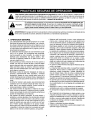
&
&
Este simbolo indica instrucciones importantes de seguridad las cuales, si no se observan, pueden poner en
peligro la seguridad personal y/o la propiedad suya y de otras personas. Lea y observe todas las instrucciones de
este manual antes de intentar operar su astilladora-desmenuzadora
a gasolina. La falla en cumplir con estas instrucciones puede resultar en lesiones personales -- obedezca la advertencia.
PELIGRO:
Su astilladora-desmenuzadora
fue fabricada para operarse de acuerdo con las reglas para una
operaci6n segura en este manual. AI igual que con cualquier tipo de equipo motorizado, la falta
de cuidado o error de parte del operador puede resultar en lesiones graves. Si usted viola estas
reglas, puede causar lesiones graves a usted mismo y a otras personas.
ADVERTENClA:
El escape
del motor
de estedeproducto
contiene
substancias
qu/micas conocidas por el Estado de California
como causantes
de cancer,
defectos
nacimiento
u otras
lesiones reproductivas.
1. OPERACION
•
•
•
•
•
•
•
GENERAL
Lea cuidadosamente esta gufa del propietario en su totalidad antes de intentar armar esta mAquina. Lea, comprenday observe todas las instrucciones en la mAquina yen el
manual(es) antes de la operaci6n. Guarde este manual en
un lugar seguro para referencia futura y regular y para ordenar piezas de repuesto.
Su astilladora-desmenuzadora
es una herramienta poderosa y no un juguete. Por consiguiente sea extremadamente precavido en todo momento. Su unidad ha sido
diseRada para desempeSar dos tareas; astillar y desmenuzar la vegetaci6n hallada en un patio normal. No la
use para ningQn otro fin.
Nunca permita que niSos menores de 16 aSos operen la
unidad. Los niSos de 16 aSos de edad y mayores deben
operar solamente bajo una supervisi6n paterna estrecha.
Debe permitirse operar la unidad a individuos responsables que est6n familiarizados con estas reglas de operaci6n segura, solamente.
Mantenga el Area de operaci6n despejada de todas las
personas, particularmente
niSos peque5os y animales
dom_sticos. Apague el motor cuando estAn cerca de la
unidad. Mantenga el Area de trabajo limpia y despejada de
ramas u obstAculos que podrfan causar que se tropiece o
caiga.
AI alimentar material a este equipo, sea extremadamente
cuidadoso que no se incluyan piezas de metal, rocas, botellas, latas u otros objetos extrahos. Podrfan resultar lesiones personales o daSos a la mAquina.
Use siempre lentes de seguridad o antiparras de seguridad, durante la operaci6n y al efectuar ajustes o reparaclones, para proteger los ojos contra objetos extraSos que
pueden ser despedidos por la mAquina.
Use zapatos de trabajo resistentes, de suela aspera y
pantalones y camisa ajustadas. Se recomiendan camisas
y pantalones que cubran los brazos y las piernas y zapatos de puntera de acero. No use ropas holgadas ni joyas y
sujete el cabello para que est_ por encima de los hornbros. Pueden quedar atrapadas en las piezas m6viles.
Nunca opere una unidad con los pies descalzos, sandalias
o zapatillas. AI alimentar material en la canaleta de la astilladora o en la tolva de la desmenuzadora, use guantes.
•
Mientras est6 funcionando el motor, nunca coloque sus
manos, pies o cualquier parte de su cuerpo dentro de la
tolva de la desmenuzadora, canaleta de la astilladora, abertura de descarga ni cerca de cualquier pieza giratoria.
Mant_ngase alejado en todo momento de la abertura de
descarga. Use un palo de diAmetro pequeSo y NO SUS
MANOS, si fuera necesario empujar el material dentro de
la canaleta de la astilladora o tolva de la desmenuzadora.
• Si por alguna raz6n es necesario destapar la toma de alimentaci6n o de la abertura de descarga o inspeccionar o
reparar cualquier parte de la mAquina donde una pieza
m6vil puede entrar en contacto con su cuerpo o ropa,
apague la mAquina, permita que se enfrfe, desconecte el
cable de la bujfa de la bujfa y al6jelo de la bujfa antes de
intentar destapar, inspeccionar o reparar.
= No opere la unidad mientras estA bajo la influencia del alcohol o las drogas.
• La mAquina debe operarse sobre una superficie nivelada
solamente. Nunca opere su unidad sobre una superficie
resbalosa, mojada, embarrada o helada. Mantenga su
Area de trabajo limpia y libre de ramas u obstAculos que
pueden causar que usted se tropiece y caiga. No se incline demasiado. El mantenerse firmemente parado y en
equilibrio es esencial para prevenir accidentes.
No permita que se acumule material procesado en el Area
de descarga ya que esto prevendrA una descarga adecuada y puede resultar en un contragolpe de la canaleta de la
astilladora.
•
•
•
•
•
•
Mantenga su rostro y cuerpo detrAs de la canaleta de la
astilladora para evitar un rebote accidental del material.
No transporte la maquina mientras el motor estA funcionando.
Si el mecanismo de corte golpea un objeto extrafio o si su
mAquina comienza a emitir un ruido o vibraci6n no comt_n,
apague inmediatamente el motor, desconecte el cable de
la bujia y mueva el cable alejado de la bujfa. Permita que
la mAquina se detenga y efectt3e los pasos siguientes.
Inspeccione por da5os.
Repare o reemplace las piezas daSadas.
Inspeccione por piezas flojas y ajuste para asegurar una
operaci6n segura continuada.
• Nuncatratederetirarnivaciarlabolsacolectora
cuando
elmotorestAfuncionando.
Apague
elmotoryespere
hastaquelahelicesedetenga
completamente.
Lah_licecontint_a
girando
durante
unossegundos
despu6s
deapagar
elmotor.
Nunca
coloque
ninguna
partedesucuerpo
enel
Areadelahelicehastaqueesteseguroquelaheliceha
detenido
sugiro.
• Elsilenciador
y el motorsecalientan
y pueden
causar
quemaduras.
Nolostoque.
• Nopermita
quehojasuotrosdesechos
seacumulen
sobreel silenciador
delmotor.Losdesechos
podrfan
encenderse
ycausar
unincendio.
• Nunca
tratededesmenuzar
oastillarmaterial
masgrande
queelespecificado
enestemanual.
Puederesultar
enlesionespersonales
odafiosa lamaquina.
• Nooperelamaquina
sinelfiltroo cubierta
sobrelatoma
deairedelcarburador,
excepto
paraajustar.
Laextracci6n
detalespartes
puedecrearunriesgo
deincendio.
• Uses61o
losaccesorios
aprobados
paraestamaquina
por
el fabricante.
Lea,entienda
y observe
todaslasinstrucclonesprovistas
conelaccesorio
aprobado.
• Si ocurrensituaciones
quenoestAncubiertas
pereste
manual,
useconcuidado
y buenjuicio.Paraasistencia
consulte
consudistribuidor.
• Mantenga
eldeflector
delacanaleta
dedescarga,
lapuertadelacanaleta
delaastilladora
ytodaslasotrasguardas
y mecanismos
deseguridad
ensu lugary funcionando
correctamente.
• Operelaunidad
alaluzdeldfasolamente.
Nooperelaunidaddenoche
o enAreas
obscuras
donde
suvisi6npueda
esta[,r
restringida.
b. Vuelva a colocar la tapa de gasolina y limpie la gasolina derramada antes de arrancar el motor, ya que
puede causar un incendio o explosi6n.
c. Apague todos los cigarrillos, cigarros, pipas y otras fuentes de encendido.
d. Nunca cargue combustible a la unidad bajo techo ya
que los vapores inflamables se acumularAn en el Area.
e. Nunca almacene la mAquina ni el recipiente de combustible bajo techo donde haya llamas expuestas o
chispas, tales como calentadores
de agua caliente a
gas,, secadora de ropas u hornos.
Nunca haga funcionar su mAquina en un Area cerrada ya
que el escape del motor contiene mon6xido de carbono,
que es un gas inodoro, ins/pido y envenenador mortal.
Para reducir el riesgo de incendio, mantenga el motor y el
silenciador libre de hojas, grama, y otras acumulaciones
de desechos. Limpie los derrames de combustible y
aceite. Permita que la unidad se enfrie por 5 minutos por
Io menos antes de arrancar.
•
•
•
AsegQrese que la helice y todas las piezas m6viles esten
detenidas, antes de limpiar, rep&rar o inspeccionar.
Desconecte el cable de la buj/a y mantengalo alejado de
la bujia para prevenir el arranque accidental. No use soluciones inflamables para limpiar el filtro de aire.
Inspeccione la cuchilla y los tornillos de montaje del motor
a intervalos frecuentes, por un buen ajuste. Tambi6n inspeccione visualmente las cuchillas por desgaste y/o
dafios (por ej. doblada, agrietada). Reemplace con cuchillas que cumplan con las especificaciones originales del
equipo.
Mantenga todas las tuercas, pernos y tornillos bien ajustados para asegurarse que el equipo est_ en buenas condiclones de trabajo.
Nunca manipule los mecanismos de seguridad. Inspecclone regularmente su operaci6n apropiada.
Despu_s de golpear un objeto extrafio, apague inmediatamente el motor, desconecte el cable de la buj/a de la bujia,
e inspeccione completamente la unidad por dafios. Repare el dafio antes de arrancar y operar la unidad.
No altere ni manipule la graduaci6n del regulador del motor. El regulador controla la velocidad operativa maxima
del motor. Es peligroso hacer funcionar el motor a una veIocidad excesiva y causarA dafios al motor y a otras piezas
m6viles de las maquinas.
•
•
2. NINOS
Pueden ocurrir accidentes trAgicos si el operador no esta
alerta a la presencia de nifios pequefios. Los nifios se sienten atrafdos a menudo a la astilladora-desmenuzadora
y a la
actividad de astillado y desmenuzado. Nunca suponga que
los nifios permaneceran donde usted los vio por t31timavez.
• Mantenga a los nifios fuera del Area de trabajo y bajo la
mirada vigilante de un adulto responsable que no sea el
operador.
• Este alerta y apague la unidad si un nifio entra al Area.
• Nunca permita que nifios menores de 16 aries de edad operen la astilladora-desmenuzadora.
•
•
•
3. SERVIClO
Sea muy precavido al usar gasolina y otros combustibles. Son
extremadamente inflamables y los vapores son explosivos.
a. Almacene el combustible y aceite en recipientes aprobados, alejados del calory de las llamas expuestas, fuera del alcance de los nifios. Inspeccione y agregue
combustible antes de arrancar el motor. Nunca retire la
tapa de gasolina ni vierta combustible mientras el motor
esta funcionando. Permita que el motor se enfrfe por
dos minutos por Io menos antes de cargar combustible.
4. SU RESPONSABILIDAD
Restrinja el uso de esta maquina
,_
motorizada
a
las
instrucciones
en este
manual
las advertencias
personas quee lean,
comprendan
y observen
y en la mAquina.
PARA
REFERENCIA
FUTURA
GUARDE
ESTAS
INSTRUCClONES
Esta unidad estA equipada con un motor de combustion interna y no debe usarse en o cerca de tierras no mejoradas
cubiertas de bosques, matorrales, y/o hierbas, a menos que el sistema de escape est6 equipado con un supresor
de chispas que cumpla con las leyes del estado o federales aplicables (de existir). Si se usa un supresor de chispas
debe ser mantenido en buenas condiciones de trabajo por el operador.
En el Estado de California Io indicado arriba es requerido por ley (Secci6n 4442 del C6digo de Recursos Pt_blicos
de California). Otros Estados pueden tener leyes similares. Las leyes federales se aplican en las tierras federales.
EstA disponible un supresor de chispas para el silenciador en su Centro de Servicio Autorizado Sears mas cercano
(Vea la secci6n de PIEZAS DE REPUESTO de este manual).
4
IMPORTANTE:
Esta unidad se despacha sin gasolina ni
aceite en el motor. Vea la secci6n de OPERACION de este
manual para las recomendaciones sobre combustible y
aceite de motor adecuados, despues del ensamblado.
NOTA: Para determinar los lados izquierdo y derecho de su
astilladora-desmenuzadora,
parese detras de la unidad con
el motor en posiciSn mas alejado de usted.
\
Su astilladora-desmenuzadora
ha sido completamente
ensamblada de fAbrica excepto por el conjunto de la tolva,
canaleta de la astilladora, canaleta de descarga y la bolsa
colectora.
Estas piezas se despachan sueltas en la caja. Se incluyen
tambien en la caja un par de gafas de seguridad y una botella
de aceite.
\
Tolva
1. EXTRAIGA LA ASTILLADORADESMENUZADORA
DE LA CAJA
o Corte las esquinas de la caja.
= Extraiga todas las inserciones de empaque.
= Extraiga todas las piezas sueltas incluyendo el manual del
propietario. Vea la figura 1.
• Ruede la astilladora-desmenuzadora
fuera de la caja.
• Antes de desechar la caja, asegQrese que todas las
piezas y la literatura hayan sido retiradas de la misma.
Canaleta de descarga
2. PIEZAS SUELTAS
a.
b.
c.
d.
e.
f.
g.
Conjunto de la tolva
Canaleta de descarga
Canaleta de la astilladora
Bolsa colectora
Botella de aceite
Gafas de seguridad
Manual del Propietario (no se muestra en la figura 1)
Gafas de
seguridad
Canaleta de la
astilladora
Bolsa colectora
Botella de
aceite
Figura 1
5
3. HERRAMIENTAS
REQUERIDAS
1. Llaves de 1/2" o ajustables
2. Llaves de 7/16" o ajustables
3. Embudo
4. DESCONEXlON
•
•
•
DE LA BUJIA
Desconecte el cable de la bujfa y mu_valo alejado de la
bujfa antes de ensamblar la astilladora-desmenuzadora.
Vea la figura 2.
Cable de la bujia
6. FIJAClON DEL CONJUNTO
LA TOLVA
•
•
•
•
•
Figura 2
•
5. FIJACION DE LA CANALETA
DESCARGA
DE
Coloque la segunda arandela sobre el perno hexagonal
dentro de la otra mitad de la bisagra. Asegure con una
contratuerca hexagonal. Ajuste seguramente.
Asegure ambos lados de la canaleta de descarga al armaz6n usando las perillas que extrajo antes. Ajuste las
perillas mariposa.
DE
Extraiga el perno hexagonal largo de 8-3/8" y la tuerca
hexagonal del fondo de la abertura de la gufa de entrada.
Coloque el conjunto de la tolva en el suelo y suj_telo en la
posici6n ilustrada en el paso 1 de la figura 4.
Mientras sujeta la tolva, empuje la puerta pivote de la tolva
hacia adentro de esta _ltima. Vea la figura 4.
Deslice el conjunto de la tolva hacia el armaz6n de la astilladora-desmenuzadora
de manera que la gu_a superior
del conjunto de la tolva se deslice debajo de la arandela
de tope a cada lado de la gufa de entrada. Vea la figura 4.
Alinee los dos orificios (uno en cada lado) de la tolva inferior con los dos orificios (uno en cada lado) de la gufa de
entrada.
Inserte el perno hexagonal (que usted extrajo antes)
desde la izquierda a trav_s del orificio de la tolva y de la
gufa de entrada. Inserte la tuerca hexagonal sobre el
perno desde el otro lado. Vea el recuadro de la figura 4.
Abertura de la guia de entrada
•
•
•
Extraiga las perillas mariposa de cada lado de la abertura
de descarga de la astilladora-desmenuzadora.
Vea la figura 3.
Usando dos Ilaves de 7/16", extraiga la contratuerca
hexagonal, los dos separadores y el perno hexagonal del
conjunto del armaz6n. Para facilitar el ensamblado, no
extraiga el segundo separador del perno hexagonal.
Coloque en posici6n la canaleta de descarga en la abertura de descarga. Inserte el perno hexagonal y el separadora traves de la bisagra en la canaleta de descarga y en
el armaz6n (el separador calza dentro de la bisagra). Vea
el recuadro de la figura 3.
Orificio
Puerta pivote de la tolva
Tuerca hexagonal
Perno hexagonal
Bisagra
dela de
to
Perilla
mariposa
\
\
entrada
descarga
Figura 3
Tolva
Perilla mariposa
Figura 4
Tuerca
hexagonal
o
Ajuste el perno. Esto asegurar_, el conjunto de la tolva a la
gufa de entrada.
Para elevar la tolva, sujetela por el mango y lev_ntela
hasta que calce en posici6n. Vea la figura 5.
Para bajar la tolva, suj6tela por el mango y tire de la barra
de desenganche.
La tolva deberfa descender. Vea la
figura 5.
Eleve la tolva
•
Extraiga los dos juegos de pernos hexagonales, tuerca de
seguridad y arandela plana, de los dos orificios en el extremo superior del estribo.
• Coloque la canaleta de la astilladora sobre los pernos soldados de manera que la ranura en la canaleta est_ orientada hacia el fondo. Alinee los tres orificios en la canaleta
con los tres pernos soldados. Vea la figura 6.
• Asegure con tres pares de arandelas acopadas y tuercas
hexagonales que usted extrajo antes. No ajuste las tuercas en este momento. Asegerese de colocar el lado acopado de la arandela contra la canaleta de la astilladora.
• Su unidad se despacha con uno de los extremos del estribo ya asegurado al armaz6n inferior. Afloje los pernos que
aseguran el estribo al armaz6n.
• Alinee los orificios en la canaleta con los orificios en el estribo. Vea la figura 6.
• Inserte uno de cada uno de los pernos hexagonales, tuercas de seguridad y arandelas planas (que extrajo antes) a
trav_s de cada orificio en la canaleta y el estribo. Vea la
figura 6 para el orden correcto. Ajuste los pernos.
° Ajuste los pernos que aseguran el estribo al armaz6n.
• Ajuste las tres tuercas en los pernos soldados.
/
la barra de
desenganche
Figura 5
7. FIJACION DE LA CANALETA
LA ASTILLADORA
•
8. FIJACION DE LA BOLSA
COLECTORA
DE
Su astilladora-desmenuzadora
est_ equipada con una bolsa
colectora para colectar el material desmenuzado.
• Para colocar la bolsa, coloque la abertura de la misma sobre el deflector de la canaleta de manera que cubra completamente el deflector de la canaleta.
• Accione el brazo m6vil sobre la soga de arrastre y tire de
esta _ltima hasta que la bolsa est_ ajustada alrededor de
la abertura de la canaleta. Suelte el brazo m6vil hasta que
calce en posici6n. Vea la figura 7.
Extraiga las tres arandelas acopadas y las tuercas hexagonales de los pernos soldados al lado de la abertura del
lado izquierdo del armaz6n. Vea la figura 6.
Perno
soldado
Perno
soldado
a de
_vil
Pernc
hexagonal
Canaleta de
descarga
Bolsa
colectora
Perno
soldado
Figura 7
Figura 6
7
Antes de operar su astilladora-desmenuzadora
ustraciones con su astilladora-desmenuzadora
Guarde este manual para referencia futura.
lea este manual del propietario y las reglas de seguridad. Compare las il- I
para familiarizarse con la ubicaci6n de los varios controles y ajustes.!
La operaci6n de una astilladora-desmenuzadora
puede resultar en que objetos extraSos sean despedidos contra los ojos, J
Io que puede lesionarlos gravemente. Antes de astillar o desmenuzar, o mlentras efectQe ajustes o reparaciones, use siempre las antiparras de seguridad provistas con esta unidad o protectores de los ojos.
1. CONOZCA
SU ASTILLADORA-DESMENUZADORA
Conjunto de
tolva
Canaleta de
la asti ladora
Barra de
desenganche
_
_-_
Palanca
regulador
Control
acelerador
Figura 8
2.
CONTROLES
DE OPERACION
Control
del acelerador
Regula la velocidad del motor. Vea la figura 8.
Barra de desenganche
Usada para desenganchar
figura 8.
la tolva al elevar o bajar. Vea la
Palanca del regulador
Usada para enriquecer la mezcla de combustible en el carburador al arrancar un motor frio. Vea la figura 8.
Mango del arrancador
Usado para arrancar manualmente
Canaleta de la astilladora
Permite alimentar vegetaci6n voluminosa tal como tallos o
ramas pesadas de hasta 3" de diAmetro a la h61ice para astillar y desmenuzar. Vea la figura 8.
Bolsa colectora (no se muestra)
Usada para colectar el material desmenuzado.
el motor, Yea la figura 8.
Conjunto de la tolva
Permite alimentar hojas y ramas pequeSas de hasta 1" de
di_.metro a la h_lice para astillar y desmenuzar. Haga descender la tolva para colectar material rastrillado para desmenuzar.
CUMPLE
Las astilladoras-desmenuzadoras
de Normas Nacionales
CON LAS NORMAS
DE SEGURIDAD
DE ANSI
de Sears cenforman con la norma de seguridad B71.6-1990 del Instituto Americano
Detencibn
del motor
Mueva la palanca de control del acelerador a la posici6n
STOP. Desconecte el cable de la bujia y alejelo de la bujfa
para prevenir un arranque accidental.
reglas de seguridad en las pdginas 3 y 4 de este
ADVERTENCIA:
nuevamente
a las
manual,
antes deRefierase
usar esta
astilladora-desmenuzadora. Tenga siempre cuidado.
_
3. LLENADO
ACEITE
DE GASOLINA
Y
Aceite (Envasado con la unidad)
Use aceite detergente de alta calidad solamente clasificado segL_n la clasificaci6n API de SF, SG o SH. Seleccione
el grado de viscosidad del aceite de acuerdo con su temperatura esperada de operaci6n. Siga la tabla de abajo.
Mds Frio _
32 °
_ Mds Caliente
NOTA: A pesar que los aceites de viscosidad m#ltiple
(5W30, 10W30, etc.) mejoran el arranque en tiempo fr[o, los
mismos resultaran en un consumo mayor de combustible
cuando se usan sobre los 32-°F. Inspeccione su nivel de
aceite mas frecuentemente para evitar da#os posibles al motor al funcionar con poco aceite.
Llene el motor con aceite como sigue.
• Extraiga la varilla. Vea la figura 9.
Extraiga la
varilla y Ilene
con aceite
Extraiga la tapa y
Ilene con gasolina
•
Con la astilladora-desmenuzadora
sobre una superficie
nivelada, use un embudo para Ilenar el motor con aceite
hasta la marca FULL. La capacidad es de 26 oz. aproximadamente. Tenga cuidado en no Ilenar en exceso.
•
Inspeccione
•
Agregue aceite si fuera necesario.
•
Vuelva a colocar la varilla y ajuste.
NOTA: No Ilene en exceso. La botella de aceite envasada
con la unidad contiene 26 oz. de aceite.
Gasolina
ADVERTENCIA:La experiencia indica que los combustibles
mezclados con alcohol (llamados gasohol o el uso de etanol
o metanol) pueden atraer la humedad, Io que conduce a la
separaciSn y formaciSn de #cido durante el almacenamiento.
El gas acfdico puede daSar el sistema de combustible del
motor mientras permanezca almacenado. Para evitar problemas con el motor, el sistema de combustible debe vaciarse
antes de almacenar durante 30 dfas o mas. Drene el tanque
de combustible, arranque el motor y permita que funcione
hasta que las tuberfas de combustible y el carburador est#n
vacfos. Use combustible fresco la prSxima temporada. Para
informaci6n adicional vea las instrucciones de ALMACENAMIENTO. Nunca use productos limpiadores de motor o
carburador en el tanque de combustible ya que pueden ocurrir da_os permanentes.
Llene el tanque de gasolina con gasolina como sigue.
• Extraiga la tapa del tanque de gasolina.
•
AsegQrese que el recipiente (del cual vertera la gasolina)
este Iimpio y libre de 6xido o partfculas extraSas. Nunca
use gasolina que pueda estar rancia despu_s de periodos
prolongados de almacenamiento en el recipiente.
•
Llene el tanque de combustible con gasolina fresca y libre
de plomo, para automotores. NO use etilo ni gasolina de
alto fndice de octano. Vea la figura 9.
•
Vuelva a colocar la tapa del tanque de combustible.
_
\
el nivel de aceite.
pulgada del tope del tanque de combustible para
ADVERTENCIA:
hasta
sobrepasarde 1/2
prevenir derrames Noy Ilene
permitir
la expansi6n
la
gasolina. Si la gasolina se derrama accidentalmente, mueva la astilladora-desmenuzadora
alejada del area del derrame. Evite crear fuentes de
encendido hasta que hayan desaparecido los vapores de la gasolina.
Para evitar que se agote la gasolina mientras est_ operando la astilladora-desmenuzadora,
inspeccione peri6dicamente el nivel de combustible.
Figura 9
Puede ser necesario
arrancar, si se agota
zando o astillando.
desgranadora" en la
destapar la unidad antes de poderla
la gasolina mientras est,. desmenuRefi_rase a "Retiro del tamiz de la
secci6n de SERVlCIO Y AJUSTES.
4. ARRANQUE
DEL MOTOR
NOTA: AI comienzo del ciclo de compresi6n se escuchar_ un
ruido. Este ruido est_ causado por las desgranadoras y dedos que forman parte del mecanismo desmenuzador calzando en su lugar, y debe
esperarse.
Adem_s,
las
desgranadoras y dedos har_n ruido despu6s de arrancarse
el motor, hasta que la h_lice alcance m_xima velocidad.
na ademds del operador est_ parada cerca de la
ADVERTENClA:
AsegL_resealque
ningunau operar.
persoastilladora-desmenuzadora
arrancar
No opere esta astilladora-desmenuzadora
a
menos que el deflector de la canaleta haya sido
correctamente instalado y est_ asegurado con las
perillas manuales.
5. DETENCION
NOTA: Coloque su pie firmemente contra el neum_,tico, para
prevenir que la unidad resbale.
•
•
1. Fije el cable de la bujfa.
\
DEL MOTOR
Mueva la palanca de control del regulador a la posici6n
STOP (HACIA ABAJO).
Desconecte el CABLE de la buj{a y al_jese de la buj/a para
prevenir el arranque accidental mientras el equipo est_
desatendido.
6. USO DE SU ASTILLADORADESMENUZADORA
lar ningt_n material que no sea vegetaci6n hallada
ADVERTENCIA:
intente
desmenuzar
o astilen un patio normalNo(por
ej. ramas,
hojas, ramitas,
etc.).
•
Inla
\
3.Mueva el regulador a
la posicibn "on"
\
posicibn Fast
\
4. Tire de la soga
La astilladora-desmenuzadora
est& diseSada para tres
metodos diferentes de operaci6n.
a. Pueden alimentarse hojas y ramas pequeSas de hasta
1" de di_metro (m_ximo) al conjunto de la tolva cuando
esta est_ en la posici6n elevada o bajada. Vea la figura
12.
b. Materiales voluminosos tales como tallos o ramas
pesadas de hasta 3" de diametro deben alimentarse a
la canaleta de la astilladora. Vea la figura 12.
Figura 1!
grande que el especificado dentro de la tolva y/o
ADVERTENCIA:
No decoloque
material
dentro
de la canaleta
la astilladora.
Puedemds
resultar en lesiones personales o daSos a la m_.quina.
•
•
•
•
•
•
•
•
•
•
Fije el cable de la buj{a y la bota de goma a la buj_a.
Mueva el interruptor del arrancador a la posici6n "ON".
Mueva la palanca del regulador a la posici6n CHOKE (en
la direcci6n de la flecha).
Si est_ arrancando
nuevamente
un motor caliente
despu_s de un intervalo corto, mueva la palanca del
regulador a la posici6n "No choke".
Sujete el mango del arrancador y tire lentamente de la
soga hasta que el motor Ilegue al inicio del ciclo de compresi6n (la soga ofrecera un poco de m&s resistencia en
este punto. Deje que la soga se enrolle lentamente.
Tire de la soga con una pasada r&pida, usando todo el brazo. Permita que la soga retorne lentamente al arrancador.
Cuando el motor arranca, mueva la palanca del regulador
a la posici6n intermedia del regulador hasta que el motor
funcione con suavidad y a continuaci6n a la posici6n No
Choke.
Si el motor no arranca despu_s de tres tirones, mueva la
palanca del regulador a la posici6n No Choke y tire nuevamente de la soga del arrancador.
Si el motor detona pero no continda funcionando,
mueva la palanca del regulador a la posici6n de Full Choke y
tire nuevamented ela soga.
Mueva la palanca del regulador a la posici6n OFF a medidaque se calienta el motor.
Si fuera necesario empujar el material dentro de la astilladora-desmenuzadora,
use un palo de di&metro pequefio y
NO SUS MANOS. El palo debe ser suficientemente peque5o como para molerse si penetra al conjunto de la
h_lice.
7. DESCENSO
LA TOLVA
DEL CONJUNTO
DE
•
Para bajar el conjunto de la tolva, use una mano para
sujetar el mango en el tope del conjunto de la tolva y
lev_ntelo ligeramente. Vea la figura 5.
• Tire hacia arriba de la barra de desenganche y baje el
conjunto de la tolva al suelo. Suelte la barra. Vea la figura
5.
_
canaleta hasta que la unidad se haya detenido
DVERTENCIA: Nunca extraiga el deflector de la
completamente.
Es importante mantener afiladas la cuchilla desmenuzadora
y las cuchillas astilladoras. Si cambia la composici6n del material de descarga (se convierte en fibroso, etc.) o si disminuye considerablemente
la velocidad
a la cual se
10
descarga
elmaterial,
esposible
quelacuchilla
desmenuzadoray/olascuchillas
astilladoras
est_ndesafiladas
yrequieranafilarseo reemplazarse.
Refierase
a la secci6nde
Servicio
yAjustes.
ADVERTENClA:
La astilladora-desmenuzadora
descarga materiales con considerable velocidad.
Mantdngase alejado del _rea alrededor de la
canaleta de descarga. AI extraer o fijar la bolsa,
cambiar bolsas o extraer el material desmenuzado, detenga siempre el motor y desconecte el
cable de la bujfa. Use gafas de seguridad y
guantes siempre que use su astilladora-desmenuzadora.
IMPORTANTE:
Hayuntamizdedesgranadora
ubicado
dentrodelarmaz6n
enel _.readedescarga.
Extraiga
y limpie
seg6nlasinstrucciones
delasecci6n
deServicio
y Ajustes.
Material desmenuzado
pulgada de didmetro
de hasta 1
/
Baje la tolva para colectar el material
rastrillado, para desmenuzar.
Atrape el material desmenuzado
en la bolsa colectora
\
Astille materiales de hasta 3
pulgadas de didmetro
Figura 12
1. RECOMENDACIONES
GENERALES
° Todos los ajustes en la secci6n de Servicio y Ajustes de
este manual deben efectuarse una vez por temporada por
Io menos.
° Siga el programa de mantenimiento proporcionado abajo.
° Inspeccione peri6dicamente todos los sujetadores y asegt_rese que esten firmes.
° AI efectuar el mantenimiento, observe siempre las reglas
de seguridad.
° La garantfa de esta astiltadora-desmenuzadora
no cubre
artfculos que han sido sometidos a abuso del operador o
negligencia. Para recibir todo el valor de la garantfa, el operador debe mantener la astilladora-desmenuzadora
seg5n se instruye en este manual.
• Para mantener adecuadamente su unidad, se deben efectuar algunos ajustes peri6dicos.
_
11
to o ajustes, siempre
detenga
el motor y
ADVERTENCIA:
Antes
mantenimiendesconecte el cable
de de
la efectuar
bujfa. Nunca
extraiga
la canaleta de descarga hasta que el motor se
haya detenido completamente.
MANTENIMIENTO
@
I
O
O
f
Aceitar los puntos de pivote
FECHAS DE SERVICIO
_/
a
O
Limpiar la desmenuzadora
*/
_/
n
Inspeccionar
el aceite del motor
_/
Cambiar el aceite del motor
0
_J
_/
Limpiar el filtro de aire
_/
Limpiar el motor
_/
Reajustar la bujia
_J
Limpiar el silenciador
_/
4
_/INSPECCIONAR
2. LIMPIEZA
•
•
Para drenar el aceite:
• Drene el aceite mientras el motor est,. caliente. Siga las instrucciones de abajo.
• Saque la tapa de drenaje de aceite. Colecte el aceite en
un recipiente adecuado.
• Cuando se ha drenado el motor de todo el aceite, vuelva
a colocar el tap6n de drenaje bien ajustado.
• Llene con aceite fresco. Refierase a la secci6n de
LLENADO DE GASOLINA Y ACEITE.
• Vuelva a colocar la varilla.
Limpie la astilladora-desmenuzadora
con agua corriente
de una manguera, sobre el conjunto de la tolva y la tolva
de la astilladora, con el motor funcionando. Permita que la
astilladora-desmenuzadora
se seque completamente.
Lave peri6dicamente la bolsa con agua. Permita que se
seque bien a la sombra. No use calor.
3. MANTENIMIENTO
DEL MOTOR
Aceite de motor
Filtro de aire
El filtro de aire impide que la suciedad, polvo, etc. dafiinos,
penetren al carburador y sean forzados dentro del motor yes
importante para la duraci6n del motor y el rendimiento. El filtro de aire consiste de un prefiltro o filtro de espuma, y un illtro de papel. Nunca haga funcionar su motor sin que el filtro
de aire est_ completamente ensamblado.
•
Use aceite detergente de alta calidad solamente de clasificaci6n API de servicio SF, SG o SH. Seleccione el grado
de viscosidad del aceite de acuerdo con su temperatura
esperada de operaci6n. Para la tabla de viscosidad refi6rase a la pAgina 10 de este manual.
• El motor de cuatro ciclos de su astilladora-desmenuzadora consumirA normalmente algo de aceite. Por consiguiente revise regularmente el nivel de aceite, cada cinco
horas de operaci6n aproximadamente y antes de cada
USO.
•
•
Apague el motor y espere varios minutos antes de inspeccionar el nivel de aceite. Con el motor nivelado, el aceite
debe estar en la marca FULL de la varilla de medici6n.
Cambie el aceite del motor despues de las primeras cinco
horas de operaci6n, y cada veinticuatro horas despues.
12
l
Para prestar servicio al filtro de aire
1. Preste servicio al prefiltro despues de cada 25 horas de
uso, o por Io menos una vez por temporada.
2. Preste servicio filtro cada 100 horas de uso, o por Io
menos una vez por temporada.
3. Preste servicio al prefiltro y al filtro m_s frecuentemente
bajo condiciones polvorientas.
• Extraiga la tuerca mariposa y la cubierta. Vea el recuadro
de la figura 13, para la ubicaci6n.
Aleta de enfriamiento
Figura 14
.f
Base
_'_
Cubierta
Tuerca
Mariposa
Papel De
Filtro
Filtro De Espuma
(Si Asi Equipado)
Anualmente o despu_s de cada 25 horas de uso, Io que
ocurra primero, extraiga el armaz6n del ventilador y limpie
tas areas mostradas en la figura 14 para evitar una
velocidad excesiva, un calentamiento excesivo y da5os al
motor. Limpie m_s frecuentemente si fuera necesario.
Figura 13
NOTA: No se recomienda limpiar con un chorro potente de
agua ya que el agua podr[a contaminar el sistema de combustible.
•
Deslice el prefiltro fuera del filtro. Limpie completamente
interior de la base y la cubierta.
de las Areas circundantes puede exceder los
ADVERTENCIA:
temperatura
150-°F
(65-°0). EviteLaesas
_.reas. del silenciador y
el
Limpie el prefiltro como sigue:
a. Lave en una soluci6n de agua y detergente, y exprima
(no retuerza) hasta que se haya eliminado toda la
suciedad
b. Enjuague completamente en agua limpia.
c. Envuelva en un trapo limpio y exprima (no retuerza)
hasta que est_ completamente seco, o permita que se
seque al aire.
d. Sature con aceite de motor y exprima (no tuerza) para
distribuir el aceite y eliminar el exceso de aceite.
Bujfa
• La bujfa debe limpiarse y ajustar la separaci6n a .030" una
vez por temporada por Io menos o cada 50 horas de operaci6n. Vea la figura 15. Se recomienda el reemplazo de la
bujfa al comienzo de cada temporada. Refi6rase a la lista
de piezas del motor para el tipo correcto de bujfa.
Calibre palpador de .030"
NOTA: Reemplace el prefiltro siesta rasgado o da_ado.
•
Si es necesario, reemplace el filtro de papel (no trate de
limpiar). Instale un nuevo filtro en la base.
• Deslice el prefiltro sobre el filtro.
• Instale la cubierta y la tuerca mariposa.
• Ajuste seguramente la tuerca mariposa.
Bujia
Figura 15
Limpieza del motor
• Limpie peri6dicamente el motor. Elimine la suciedad y los
desechos con un trapo o cepillo
• Extraiga frecuentemente los recortes de grama, suciedad
y desechos de las aletas de enfriamiento, del tamiz de la
toma de aire y de las palancas y acoples. Esto ayudar_ a
asegurar un enfriamiento adecuado y una velocidad correcta del motor. Vea la figura 14.
NOTA: No limpie la bujfa con chorro de arena. La bujfa debe
limpiarse raspando o cepillando con cepillo de alambre y lavando con un solvente comerciaL
13
4. LUBRICACION
Silenciador
_i
menuzadora sin un silenciador ni manipule el
ADVERTENClA:
No Los
opere
la astilladora-dessistema
de escape.
silenciadores
o supresores de chispas dafiados pueden crear un riesgo
de incendio.
Lubrique los puntos pivote en la barra de desenganche, conjunto de la toIva, deflector de la canaleta y canaleta de la
astilladora, una vez por temporada usando un aceite liviano.
Vea la figura 16.
Inspeccione peribdicamente y reempl_celo si fuera necesario. Si su motor est,. equipado con un conjunto de tamiz
de supresor de chispas, extraiga despu_s de cada 50 horas de uso para limpieza e inspecci6n. Reemplace si esta
dafiado.
_i
araciones,
siempre
detenga
el
motor,
DVERTENCIA:
Antesdede
ajustes oalejarepdesconecte
el cable
la efectuar
bujfa y muevalo
do de la bujfa.
Lubricacion
Figura 16: Grafico de lubricaci6n
•
•
1. EXTRACCION DEL TAMIZ DE LA
DESGRANADORA
Si se tapona el area de descarga, retire el tamiz de la desgranadora y limpie el _rea como sigue.
• Apague el motor. Asegerese que la astilladora-desmenuzadora se ha detenido completamente y desconecte
el cable de la bujfa antes de destapar la canaleta.
• Extraiga las dos perillas manuales a cada lado de la
canaleta de descarga (llamado tambi_n deflector de la
canaleta).
• Levante la canaleta de descarga y col6quela fuera del
paso.
• Extraiga los dos broches tipo horquilla del cabello de las
clavijas de tipo horquilla que se extienden a trav_s del armaz6n. Extraiga las clavijas de tipo horquilla. Vea la figura
17.
• Tire desde adentro del armaz6n el tamiz de la desgranadora. Vea la figura 17.
• Limpie el tamiz rasp_ndola o lav_ndola con agua.
Vuelva a colocar el tamiz.
Coloque la canaleta de descarga en su posici6n original y
ajuste las perillas manuales.
NOTA: AsegOrese de volver a ensamblar el tamiz de la desgranadora con el lado curvo hacia abajo.
Deflector de la
canaleta
/
!
Broches tipo
horquilladelcabelIo, clavijas de tipo
horquilla
Tamiz de la
desgranadora
Tuercas
agonales,
arandelas
Canaleta
de la astilladora
Perillas manuales
Figura 17
14
2. AFILADO O REEMPLAZO
CUCHILLAS
Cuchilla de la desmenuzadora
La cuchilla de la desmenuzadora puede extraerse para afilar
o reemplazar segL_nIo siguiente:
• Desconecte el cable de la bujia y muevalo alejado de la
bujia.
• Baje el cenjunto de la telva. Bloquee el armaz6n. Vea la
figura 19.
DE LAS
Cuchillas de la astilladora
•
Desconecte el cable de la bujfa y muevalo alejado de la
bujfa.
• Extraiga el tamiz de la desgranadera segt_n se instruye en
la secci6n previa.
° Usando una Ilave de 1/2", extraiga la canaleta de la astilladora extrayendo tres tuercas hexagonales y arandelas.
Vea la figura 17.
° Usando una Ilave de 7/16", extraiga el estribo que sujeta
la canaleta al armaz6n extrayendo los pemos hexagonales.
Tornillos Allen
NOTA: AI reensamblar, la arandela acopada se coloca en la
ranura hacia el fondo de la canaleta de la astilladora con el
Caho
lado acopado contra la canaleta.
Gire manualmente el conjunto de la h61ice hasta que
ubique una de las dos cuchillas de la astilladora en la abertura de la canaleta de la astilladora. Extraiga la cuchilla,
usando una Ilave allen de 3/1 6" en el exterior de la cuchilla
y una Ilave de 1/2" en el conjunto de la h_lice (dentro del
armaz6n). Vea la figura 18.
Perno
soldado
Cuchilla
Figura 19
Extraiga las seis tuercas hexagonales de seguridad y las
arandelas de seguridad de los pernos soldados del armaz6n usando una Ilave de 1/2". Separe la astilladoradesmenuzadora
en dos mitades. Extraiga la placa de
respaldo.
NOTA: AI reensamblar, aseg#rese que las superficies grabadas de la aleta est6n orientadas hacia adentro hacia la h#lice
y que la abertura en la placa de respaldo est# orientada hacia
el fondo de la unidad.
•
•
Borde afilado
Figura 18
•
•
•
•
Extraiga la otra cuchilla de la misma manera.
Reemplace o afile las cuchillas.
Siesta afilando, aseg_rese de extraer una cantidad igual
de cada cuchilla.
•
Reensamble en order inverso. Asegt_rese que las cuchillas vuetvan a ensamblarse con el borde afilado enfrentado
en la direcci6n mostrada en la figura 18 (el borde afilado
esta ensamblado hacia la abertura ranurada en el fondo).
GradQe el par torsor de los pernos y tuercas a 250-350 libras por pulgada.
•
_)
Extraiga las dos perillas manuales y las arandelas acopadas que aseguran el deflector de la canaleta. Levante el
deflector de la canaleta.
Inserte un caSo de 1/2" 6 3/4" de di_.metro a trav6s del
tamiz de la desgranadora dentro de la h_lice, para evitar
que gire, o extraiga el tamiz de la desgranadora e inserte
un trozo de madera (2 x 4) dentro de la abertura de la
canaleta, usando una Ilave allen de 3/16" y una llave de 1/
2".
Extraiga la cuchilla extrayendo el perno central, la arandela de seguridad y la arandela ptana.
cuchilla para evitar tocar los pernos soldados en el
ADVERTENCIA:
Sea precavido al extraer la
armaz6n.
AI afilar la cuchilla, siga el &ngulo original de desgaste
como gufa. Es extremadamente importante que cada borde de corte reciba un grade igual de desgaste para prevenir una cuchilla desequilibrada.
15
• Unacuchilla
desequilibrada
causara
unavibraci6n
excesivaalgirara altasvelocidades
y puede
causardafiosa la
unidad,la cuchilla
puedeprobarse
porequilibrio
equilibr_ndola
sobreundestornillador
dehojaredonda
osobre
unclavo.Desgaste
el metaldelladomaspesado
hasta
quela unidadest6uniformemente
equilibrada.
Yeala
Figura
20.
• AIreensamblar
lacuchilla,
ajusteel pernocentralentre
550-650
pulgadas
librasy losdospernos
exteriores
entre
250y 350pulgadas
libras,o ajusteseguramente
enel
casodenotenerunaIlavedepartorsor.
1.Inserte
el destornillador
a travds del orificio
La presi6n recomendada de operaci6n de los neum_.ticos es
de 24 p.s.i. (la banda lateral del neumAtico puede indicar la
presi6n recomendada del fabricante). Se debe mantener una
presi6n igual en ambos neum_ticos.
2. La cuchilla debe estar paralela al suelo
DestornilladorX..
Cuchilla
1
o_'_)
0
i_
el reborde del neum_ttico puede causar que reviADVERTENCIA:
Una
presi6n excesiva
al asentar
ente
el conjunto del
neumAtico/aro
con una
fuerza
suficiente como para causar lesiones graves.
Suelo
AI final de la temporada prepare su astilladora-desmenuzadora para almacenamiento si la unidad no se usarA por 30
dfas o m#ts.
Figura 20
3. AJUSTE
,_
DEL CARBURADOR
las piezas m6viles, en el caso de efectuar ajustes
ADVERTENClA:
de todas
al motor mientras Mant6ngase
el mismo esta.alejado
funcionando
(por
ej. el carburador),mantengase
alejado de todas
las piezas m6viles. Tenga cuidado con las superficies calientes y el silenciador.
El carburador ha sido ajustado de f_tbrica y no debe requerir
ajustes. Sin embargo, si su motor no funciona correctamente
debido a problemas sospechados del carburador, Ileve su
astilladora-desmenuzadora
a su centro de servicio Sears
m_s cercano.
4. VELOCIDAD
NOTA" Una revisaci6n anual por su centro de servicio Sears
es una buena manera de asegurarse que su astilladora-desmenuzadora proveer_, el m_.ximo rendimiento para la pr6xima temporada.
5. NEUMATICOS
d/
--
combustible en el tanque de combustible, dentro
ADVERTENCIA:
Nunca
almacenepueden
la m_.quina
con
de
un edificio donde
los humos
alcanzar
una llama expuesta o chispa, o donde esten presentes fuentes de encendido tales como calentadores de agua caliente y de ambientes, hornos,
secadores de ropa, cocinas, motores el6ctricos,
etc.
DEL MOTOR
La velocidad de su motor de su astilladora-desmenuzadora
ha sido graduada de fabrica. No intente incrementar la veIocidad del motor o puede resultar en lesiones personales. Si
usted piensa que el motor estA funcionando demasiado r_.pido o demasiado lento, Ileve su astilladora-desmenuzadora
a
su centro de servicio Sears ma.s cercano para reparar y
ajustar.
16
_
NOTA: El estabilizador de combustible es una alternativa
aceptable para miniminizar la formaciSn de dep6sitos de
goma del combustible durante el almacenamiento.
• Agregue el estabilizador a la gasolina en el tanque de
combustible o recipiente de almacenamiento.
• Siempre siga la proporci6n de mezcla de combustible indicada en el recipiente del estabilizador.
• Despu_s de agregar estabilizador haga funcionar el motor
durante 10 minutos por Io menos, para permitir que el estabilizador Ilegue el carburador.
• No drene el tanque de combustible ni el carburador si usa
el estabilizador de combustible. Drene todo el aceite del
carter (esto debe hacerse despues que ha funcionado el
motor y estA todavia caliente) y Ilene el carter con aceite
fresco.
• Si usted ha drenado el tanque de combustible, proteja el
interior del motor como sigue.
• Extraiga la buj[a, vierta 1/2 aproximadamente (una cucharada de t_) de aceite de motor, dentro del cilindro e intente
arrancar lentamente para distribuir el aceite.
• Vuelva a colocar la bujfa.
combustible en el tanque de combustible, dentro
ADVERTENCIA:
Nunca
almacenepueden
la mAquina
con
de
un edificio donde
los humos
alcanzar
una llama expuesta o chispa, o donde est6n presentes fuentes de encendido tales como calentadores de agua caliente y de ambientes, homos,
secadores de ropa, cocinas, motores electricos,
etc.
Una revici6n anual por su centro de servicio Sears es una
buena manera de asegurarse que su astilladora-desmenuzadora proveerA el mAximo rendimiento para la pr6xima temporada.
1. ASTILLADORA-DE
SMENUZADORA
•
•
Limpie completamente la astilladora-desmenuzadora
Frote la unidad con un trapo aceitado para prevenir la oxidaci6n (use un aceite liviano o siliconas)
2. MOTOR
3. OTRO
IMPORTANTE: Es importante evitar prevenir que se formen
dep6sitos de goma en piezas esenciales del sistema tales
como el carburador, el filtro de combustible, la manguera de
combustible o el tanque, durante el almacenamiento. Tambien, la experiencia indica que los combustibles mezclados
con alcohol (llamados gasohol o que usan etanol o metanol)
pueden atraer la humedad Io que resulta en
la separaci6n y formaci6n de acidos durante el almacenamiento. El gas acidico puede dafiar el sistema de combustible del motor mientras esta en almacenamiento.
•
•
No almacene gasolina de una temporada a la otra.
Reemplace su recipiente de gasolina si comienza a oxidarse. La oxidaci6n y/o la suciedad en su gasolina
causarA problemas. Almacene la unidad en un Area limpia, seca. No almacene cerca de materiales corrosivos, tal
como fertilizantes.
NOTA: Si se almacena en una casilla no ventilada o de metal, asegOrese de proteger el equipo contra el 6xido recubri&ndolo con un aceite fiviano o siliconas.
•
•
Drene el tanque de combustible.
Arranque el motor y permita que funcione hasta que las tuberias de combustible y el carburador est6n vacios.
• Drene el carburador presionando hacia arriba la taza de
drenaje la que estA ubicada debajo del carburador. Vea la
figura 21.
• Nunca use productos limpiadores del motor o del carburador en el tanque de combustible ya que puede ocurrir un
dafio permanente.
• Use combustible fresco la pr6xima temporada.
17
PROBLEMA
CAUSA POSIBLE
ACCION CORRECTORA
El motor no arranca
1. Tanque de combustible vacfo, o
combustible rancio.
2.
Est_ desconectado el cable de la bujfa.
3. Bujfa defectuosa.
4. El control del acelerador no estA en la
posici6n correcta.
1. Llene el tanque con combustible limpio
y fresco.
2.
Conecte el cable a la bujfa.
3. Limpie, ajuste la separaci6n o reemplace.
4. Mueva el control del acelerador a la posici6r
FAST.
Perdida de potencia,
funcionamiento err_.tico
1. El cable de la bujfa est& flojo.
2. La unidad estA funcionando en CHOKE
5. El carburador est,. desajustado.
6. Filtro de aire sucio.
1 Conecte y ajuste el cable de la bujfa.
2. Mueva la palanca del regulador a la
posici6n OFF.
3. Limpie la tuberfa de combustible; Ilene el
tanque con gasolina limpia y fresca.
4. Desconecte la tuberfa de combustible
en el carburador para drenar el tanque de
combustible. Llene con combustible fresco.
5. Consulte con su centro de servicio SEARS.
6. Preste servicio al filtro de aire
El motor se sobrecalienta
1. El carburador no est,. bien ajustado
2. El nivel de aceite del motor es bajo.
1. Consulte con su Centro de Servicio SEARS.
2. Llene el c_rter con aceite apropiado.
Demasiada vibraci6n
1. Piezas flojas o h_lice daSada.
1.
La unidad no descarga
1. Esta taponada la canaleta de descarga.
1. Detenga inmediatamente el motor y
desconecte el cable de la bujfa. Limpie el
tamiz de la desgranadora y el interior del
armaz6n del ventilador.
2. Hay un objeto extraSo en la h_lice.
2. Detenga inmediatamente el motor y
desconecte el cable de la bujfa. Retire el
objeto atrapado.
1. La cuchilla desmenuzadora y/o la
cuchilla de la astilladora estAn
desafiladas.
1. Afile o reemplace la cuchilla(s).
3. La tuberfa de combustible est,. bloqueada
o combustible rancio.
4. Agua o suciedad en el sistema de
combustible.
La velocidad de descarga
disminuye
considerablemente o
cambia la composici6n
del material descargado.
Detenga inmediatamente el motor y
desconecte el cable de la bujfa. Ajuste
todos los pernos y tuercas. Efectt3e todas
las reparaciones necesarias. Si contint_a la
vibraci6n haga reparar la unidad en un
Centro de Servicio SEARS.
Por favor consulte con su centro de servicio SEARS mas cercano, para reparaciones
ajustes menores listados arriba.
18
diferentes a los
F
Sears se complace en ofrecer a sus clientes
servicio de reparaci6n de aparatos electrodom_sticos y electrbnicos de todas las marcas.
En Sears, usted puede contar con operadores en
espa_ol, a los que puede Ilamar sin cargo alguno.
Para pedir servicio de reparacibn
a domicilio,
Llame 24 horas al dia, 7 dfas a la semana
1 800-676-5811
Para ordenar piezas con entrega
a domicilio,
Llame de 7 am a 7 pm, 7 dfas a la semana
1 800-659-7O84
SEARS