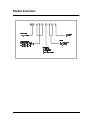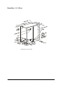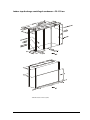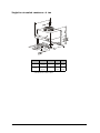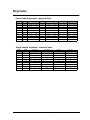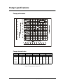
1
® NetworkAIR AFX Series TM Precision Air-Conditioning Units—60 Hz Technical Data Contents Available Models . . . . . . . . . . . . . . . . . . . . . . . . . . . . . . . . . 1 Downflow 1 Upflow front-return 1 Upflow rear-return 1 Indoor rear-discharge centrifugal condenser 1 Indoor top-discharge centrifugal condenser 1 Overview . . . . . . . . . . . . . . . . . . . . . . . . . . . . . . . . . . . . . . 3 Introduction 3 Capacity 3 Air pattern 3 Control 3 Configuration 4 Front access 4 Humidity control 4 Compliance 4 Model Selection. . . . . . . . . . . . . . . . . . . . . . . . . . . . . . . . . . 5 Standard Features . . . . . . . . . . . . . . . . . . . . . . . . . . . . . . . . 7 Microprocessor controller 7 Overall cabinet 8 Blower assembly 9 Electrical panel 9 Humidifier 9 Electric reheat 9 Refrigeration system and compressor 9 Cooling coil 10 Condenser 10 Air filter 10 Water-regulating valves 10 Airflow sensor 10 Clogged filter alarm 10 Emergency drain pan 11 Optional Features . . . . . . . . . . . . . . . . . . . . . . . . . . . . . . . 13 Emergency/environmental 13 External components 13 Control/monitoring 14 Reheat 15 System Components 15 APC NetworkAIR AFX Series: Contents i Performance Specifications. . . . . . . . . . . . . . . . . . . . . . . . . 17 Net cooling capacity—air/remote condensing 17 Net cooling capacity—water 18 Net cooling capacity—glycol 19 Performance Data . . . . . . . . . . . . . . . . . . . . . . . . . . . . . . . 21 Air system 21 Coolant requirements 21 Pump system 21 Water regulating valve–2-Way/3-Way, single seated 22 Humidification—solid state electrode canister 22 Filters 22 Evaporator coil 22 Compressor—scroll 22 Electric Reheat 23 Hot gas reheat 23 Hot water reheat 23 Steam reheat 23 Drycooler 23 Centrifugal indoor condenser 23 Physical data 24 Connection sizes 24 Electrical Data . . . . . . . . . . . . . . . . . . . . . . . . . . . . . . . . . . 25 Electric Reheat—6–14 ton 25 Electric Reheat—18–28 ton 26 Steam/hot water/or no-reheat—6–14 ton 27 Steam/hot water/or no-reheat—18–28 ton 28 Indoor centrifugal condenser units 29 Guide Specifications . . . . . . . . . . . . . . . . . . . . . . . . . . . . . . 31 General 31 Product 31 Individual systems 34 Options 36 Dimensional Data. . . . . . . . . . . . . . . . . . . . . . . . . . . . . . . . 39 Downflow—6–8 ton 39 Downflow—10–18 ton 40 Downflow—20–28 ton 41 Upflow front-return—6–8 ton 42 Upflow front-return—10–18 ton 43 Upflow front-return—20–28 ton 44 Upflow rear-return—6–8 ton 45 Upflow rear-return—10–18 ton 46 ii APC NetworkAIR AFX Series: Contents Upflow rear-return—20–28 ton 47 Indoor rear-discharge centrifugal condenser—6–8 ton 48 Indoor rear-discharge centrifugal condenser—10–18 ton 49 Indoor rear-discharge centrifugal condenser—20–28 ton 50 Indoor top-discharge centrifugal condenser—6–8 ton 51 Indoor top-discharge centrifugal condenser—10–18 ton 52 Indoor top-discharge centrifugal condenser—20–28 ton 53 Air-Cooled Condensers and Drycoolers . . . . . . . . . . . . . . . 55 Key to the model number 55 Air-cooled condenser—physical data 56 Air-cooled condenser—electrical data 57 Single-fan air-cooled condenser—6 ton 58 Dual-fan air-cooled condenser—6–14 ton 59 Triple-fan air-cooled condenser—14–20 ton 60 Dual-fan air-cooled condenser—20–26 ton 61 Triple-fan air-cooled condenser—26–28 ton 62 Drycooler . . . . . . . . . . . . . . . . . . . . . . . . . . . . . . . . . . . . . 63 Glycol cooled drycooler—physical data 63 Glycol cooled drycooler—electrical data 63 Dual-fan fluid cooler—6–8 ton 64 Triple-fan fluid cooler—10–12 ton 65 Dual-fan fluid cooler—14–18 ton 66 Triple-fan fluid cooler—20–28 ton 67 Pump Specifications . . . . . . . . . . . . . . . . . . . . . . . . . . . . . 69 Pump performance 69 Pump electrical data 69 Guidelines for Installation . . . . . . . . . . . . . . . . . . . . . . . . . 71 Room preparation 71 Unit location 71 Service access 71 Receiving the unit 71 Rigging 72 Floorstand 72 Utility connections 72 Power unit 72 Humidifier connections 72 Condensate drain 72 Water supply to humidifier 72 Water supply 73 APC Worldwide Customer Support . . . . . . . . . . . . . . . . . . 75 APC NetworkAIR AFX Series: Contents iii Available Models Downflow 6–8 ton 10–18 ton 20–28 ton Upflow front-return 6–8 ton 10–18 ton 20–28 ton Upflow rear-return 6–8 ton 10–18 ton 20–28 ton Indoor rear-discharge centrifugal condenser 6–8 ton 10–18 ton 20–28 ton Indoor top-discharge centrifugal condenser 6–8 ton 10–18 ton 20–28 ton APC NetworkAIR AFX Series: Available Models 1 Overview Introduction The APC AFX series precision air-conditioning system provides compact, quiet, efficient, and reliable system solutions in the expanding precision airconditioning market. The AFX series is offered in a wide variety of capacities, configurations, and air patterns within an extremely compact cabinet size. Precision environmental control requirements now reach far beyond the confines of the traditional data center or computer room to encompass a larger suite of applications, referred to as technology rooms. Typical technology room applications included: • Computer rooms • Telecommunication facilities • Clean rooms • Power equipment • Medical equipment rooms • Archives • LAN environments A worldwide network of APC representatives is fully qualified to provide engineering, sales, installation and service for our products. Our commitment to quality is demonstrated by the APC industry-leading two-year parts warranty. Capacity Available are 6 through 28 nominal tons (20 kW–96 kW) in nine models and 3 cabinet designs. Air pattern Downflow units discharge air into the raised floor plenum eliminating the need for air distributing ductwork. This enables the owner to locate the unit where space is available or relocate the unit as the room changes or expands. These units are suitable for areas with raised floors greater than 12" (305 mm) high. Air is drawn in through the top of the unit. Downflow units also include a static regain duct which increases performance and efficiency while reducing noise level. Upflow units discharge air into either a plenum or ductwork. These units are suitable for areas with raised floors less than 12" (300 mm) high. Air is drawn in through the front on the standard design or optionally from the rear of the unit. Control The microprocessor controller provides advanced integrated system operation and management ensuring simple, reliable and precise temperature and humidity control. APC NetworkAIR AFX Series: Overview 3 Configuration Air-cooled. Unit used with an air-cooled condenser. Refrigerant lines must be run between the indoor unit and the condenser. Air cooled units require low maintenance and have low operating costs. Configurations are: • Air-cooled with remote outdoor condenser. • Air-cooled with indoor floor mounted condenser. Water-cooled. Unit used with a cooling tower or other source of water. Field refrigeration piping is eliminated by a factory sealed and tested system. Water piping to and from the unit is required. Glycol-cooled. Unit used with a drycooler. The need for field refrigeration piping is eliminated by a factory sealed and tested system. The glycol piping is sealed, eliminating costly water treatment often encountered with open cooling towers. Remote-condensing. Unit used with a remote air-cooled condensing unit which includes the compressor(s). This allows key maintenance procedures to be located outside the critical environment helping eliminate access by maintenance personnel in high security areas. Front access The AFX Series has full service front access for routine servicing of components. Front access also narrows the footprint of the unit making it possible for units to be placed side by side. Humidity control Humidity is managed through a self-contained steam canister humidifier for maximum efficiency and ease of maintenance. Dehumidification control is assured with a split evaporator coil which decreases the humidity level without over-cooling the space, therefore reducing the need for electric reheat. Compliance The AFX Series has received agency approvals by ETL and MEA#223-99-E. Electrical systems comply with NEC and UL 1995 standards. 4 APC NetworkAIR AFX Series: Overview Model Selection AFX – X X X – X – X X – X 3URGXFW6HULHV ' 'RZQIORZ $); 8 8SIORZ $);VHULHV 9ROWDJH &RROLQJFDSDFLW\LQ QRPLQDOWRQQDJH;;; %$ ² .$ 0$ &RQILJXUDWLRQ $ $LUFRROHG : :DWHUFRROHG * *O\FROFRROHG 5 5HPRWHFRQGHQVLQJ APC NetworkAIR AFX Series: Model Selection 5 Standard Features Microprocessor controller The microprocessor controller provides state of the art control for a wide variety of environmental applications including the demanding requirements of data centers, control rooms, clean rooms, switch rooms, MRI facilities, CAT scan facilities and UPS Rooms. Operator Interface is provided by the four-line, 80-character backlit LCD display. A user-friendly menu structure along with clearly defined prompts allow the operator to easily move about the program. Within the configuration menu the operator will find numerous selections allowing the AFX to be tailored to meet specific requirements. Status. Complete status monitoring is provided within the status menu of the microprocessor controller. Available information includes: • • • • Current temperature Current humidity Temperature setpoint Humidity setpoint • • • • Cooling status Heating status Humidification status Dehumidification status Alarms. Quick access to any alarm condition is facilitated through the menu structure. The alarm key acts as a hot key, providing immediate access to the alarm display menu. Presence of a new alarm will sound the audible alarm. The red alarm LED on the display panel will remain illuminated until all alarms have been cleared. The temperature and humidity alarm setpoints are adjustable. Alarm annunciations include: • • • • Loss of airflow Clogged filter High head pressure Low suction pressure • • • • High temperature Low temperature High humidity Low humidity Setpoints. The microprocessor is provided with independent setpoints for: • Heating • Cooling • Humidification • Dehumidification Automatic setpoint crossover protection will prevent the setting of the heat setpoint above the cool setpoint and the humidify setpoint above the dehumidify setpoint. Setpoint adjustment can be restricted to only operators with knowledge of the security codes set within the security menu structure. Configuration. Flexibility is offered through the use of the configuration menu. Operating requirements are satisfied by changing the configuration settings. New configurations are stored in EEPROM and protected from unauthorized tampering by the four-digit security password, selected in the security menu. APC NetworkAIR AFX Series: Standard Features 7 Configuration options include: • • • • • Fahrenheit or celsius display Compressor minimum on time Compressor minimum off time Power loss restart time delay Redundant unit grouping • • • • • Alarm input polarity Alarm enable Temperature deadbands Humidity deadbands Small room delay Common alarm contact. A common alarm relay is installed on every microprocessor. In the event of an alarm condition, the relay will change state. The user can select which alarms change the state of the relay. This feature allows for remote enunciation of alarm status. Run times. The major components within the unit (motor, humidifier, and compressor) have independent run timers that monitor and store accumulated run hours on the components. The run timers are provided with operator adjustable run time alarms. Security. Multiple security levels prevent unauthorized adjustment of important system parameters. The user may select a four-digit password for setpoint and configuration changes. Should the password be forgotten, APC can provide temporary access. Monitoring. With the addition of a network communications card the microprocessor may interface with the locally installed APC remote monitoring and control system. Gateways are available for interfacing with building management systems. Please check with APC for compatibility with your building management system. Cool inhibit. Prevents the unit from over-cooling during the dehumidification cycle. If the space temperature falls below a user adjustable setpoint, cooling will become inhibited until the space temperature returns to setpoint. Cool override. A manual toggle switch will allow one compressor operation in the event of a microprocessor failure. The cool override can be field wired to a snap acting thermostat for cooling control. Remote shutdown. Events external to the unit, such as activation of a fire suppression system may require the unit to shut down remotely. Additionally this feature may be tied into a BMS that would allow remote control of the units on/off status. Remote relay shutdown. Remote shutdown of the NetworkAIR system can be done by a factory installed relay. The relay can be ordered with a 24, 120, or 240 volt coil. The relay must be powered by others to disable the NetworkAIR system. Overall cabinet The frame is constructed of heavy gauge steel for maximum strength. Steel access panels are insulated for quieter operation. The unit has been designed for full service access from the front. The flush mounted panels are removable using convenient quarter-turn fasteners. The access doors for the electronic controller and electrical panel can be opened without interrupting the operation of the unit. 8 APC NetworkAIR AFX Series: Standard Features Blower assembly The AFX series includes multiple, centrifugal blower assemblies that have been engineered for quiet, reliable operation. Lower blower speeds reduce noise and extend belt and bearing life to 200,000L10 hours. Permanently lubricated bearings, a single-belt variable pitch drive, and an adjustable motor base all ensure dependable operation. In addition, the air return patterns evenly distribute air across the cooling coil. Electrical panel The electrical panel contains the contactors, starters, overload protection devices, and input power circuit breakers. Each wire (except jumpers) is numbered every 3" (80 mm), or color coded to facilitate circuit tracing when installing and servicing the unit. Each AC power circuit is individually circuit-braker protected on all three phases. All compressor and motor devices are thermally and short circuit protected. The electrical panel is easily accessible from the front of the unit, and its modular construction allows access to major components within the unit cabinet. An emergency cool override switch can be manually activated to initiate cooling and a field wired thermostat can be utilized to control cooling operation. All electrical components are UL-listed and-recognized and all wiring conforms to NFPA 70 (NEC) and UL 1995 requirements. Humidifier The humidifier utilizes a pure steam generator specifically designed for hitech area environmental control. The pure steam eliminates contaminating mineral deposits, potentially deadly bacteria, white dust and excessive humidity. The humidifier requires little or no scheduled maintenance. Automatic flushing combined with an indicator that signals when the canister is to be changed, ensure maintenance free operation. Electric reheat A three-phase electrical resistance heater sized to offset the sensible cooling capacity in the dehumidification mode is incorporated in each AFX series unit. The reheat elements are low watt density sheathed components. The reheat is three phase to provide even phase loading. Reheat elements are electrically and thermally protected. Refrigeration system and compressor The refrigeration system operates under an automatic microprocessor controller for greater efficiency and accuracy. The heavy-duty compressors are designed for year-round operation with a 15-year life expectancy. The performance of the refrigeration system is enhanced by use of Scroll Compressor Technology. Scroll compressors offer many advantages over older technology semi-hermetic compressors. Vibration in the system is greatly reduced by elimination of the reciprocating masses found in the semihermetic compressor. Risk of refrigeration leaks at compressor gaskets are eliminated with the scroll compressors fully welded hermetic shell. The design of the scroll is more tolerant to liquid flood back than the traditional reciprocating compressor. Power consumption at full load is greatly reduced with higher EER’s of the scroll. In addition reliability is enhanced due to the fewer moving parts required using scroll technology. The end result is a refrigeration system that offers the user optimized performance, efficiency and reliability. APC NetworkAIR AFX Series: Standard Features 9 Each refrigeration system includes: • Thermal expansion valve with equalizer • High and low pressure switches • Sight glass with moisture indicator • Filter drier • Liquid line solenoid valve Cooling coil The AFX utilizes dual distributors on one circuit of the refrigeration system. During dehumidification the smaller distributor is turned off effectively reducing the active circuits of the evaporator coil. During this mode of operation the evaporating temperature is decreased, resulting in a lower coil surface temperature. This reduction of the coil temperature decreases the sensible heat ratio of the coil allowing a greater percentage of moisture removal. Additionally the warmer air leaving the inactive circuits of the evaporator coil blends with the near saturated air from the active circuits raising the dry bulb temperature of the blended air well above saturation. Condenser Water-and glycol-cooled systems employ a brazed plate condenser that uses the latest heat transfer technology. Type 316L stainless plates are brazed together in a vacuum furnace and comply with ASME pressure vessel code. Pressure rating is 450 psi (3100 kPa). Air filter The filtration of conditioned air is extremely vital to maintaining the clean, particle-free environment required by electrical equipment. The AFX Series uses 30% efficient (ASHRAE 52.1–92), 4" (102 mm) deep filters, with full depth filter pleats. In addition to high filtration properties, these filters produce a lower pressure drop than standard filters so less energy is required during normal operation. Filters are easily replaced from the top on downflow units and from the front on upflow units. Water-regulating valves The water-and glycol-cooled systems maintain proper performance by sensing refrigerant discharge pressure and regulating the amount of water or glycol supplied to the condenser. Two-way and three-way valves are available. The standard valve pressure rating is 150 psi (1030 kPa). Airflow sensor The air proving switch is continuously monitored by the microprocessor. Upon detection of a loss of air flow the microprocessor will deactivate: cooling, heating, humidification and dehumidification. After the air flow has been restored for a predetermined period of time the microprocessor will reactivate the functions as needed. Clogged filter alarm An adjustable air pressure differently switch senses the pressure drop across the filters. Upon sensing an excessive pressure drop, the switch activates the alarm circuit of the microprocessor and displays a clogged filter message simultaneously with an audible signal. 10 APC NetworkAIR AFX Series: Standard Features Emergency drain pan Systems are provided with two drain pans. The primary stainless steel condensate drain pan lies directly under the cooling coil. A secondary emergency drain pan provides additional protection by catching any water before it reaches the subfloor and becomes a problem. An optional factory supplied water detector in the emergency drain pan functions as your early warning system in the event of any water problems. A threaded flange is factory supplied for secondary drain connections. A secondary drain pan is not provided on bottom return or precool units. APC NetworkAIR AFX Series: Standard Features 11 Optional Features The following optional features are available on the AFX Series unless otherwise noted. Certain combinations of options may not be available. Emergency/ environmental Smoke detector(s). The factory installed smoke detector(s) is designed to sense smoke concentration in the return air stream. Upon detecting smoke concentration an audible and visual alarm on the microprocessor will be activated and the unit will immediately shut-down. Firestat. A Firestat is available for installation in the air stream. If the return air temperature reaches 125° F (52° C), the air conditioner will be turned off and both an audible and visual alarm will be activated on the microprocessor. Water detector(s). The solid-state water detector(s) activates an audible and visual alarm on the microprocessor when moisture is detected. The water detector is provided with 15' (5 m) of wire. Multiple detectors can be used in the optional secondary drain pan in the sub floor. Essential/non-essential lockout. When facilities have limited backup power capacity, this lockout prevents the operation of electrical loads that are not essential for continued site operation. External components Floorstand. The heavy gauge floorstand raises the unit above the subfloor to match the height of the raised floor. Heights are available from 6" to 36" (12" to 36" for downflow units) in 3" increments and are adjustable +/- 1.5". Adjustment is provided by threaded pedestals. Vibration absorbing pads are included. The floorstand, pedestal and pads ship loose. Floorstands are available for seismic applications. Air deflector. An air deflector ships loose and attaches to the floorstand for changing air direction from vertical to horizontal. Plenum. The discharge plenum mounts on top of the upflow unit to direct and distribute conditioned air. Manually adjustable, double deflecting grilles are provided on 3 or 4 sides.Plenum shall be painted to match the color of the unit. Duct flange. A 1" (25 mm) duct flange is installed on a unit to provide convenient connection to external ductwork. The duct flange can be installed at the air outlet on upflow units, or at the air inlet on downflow units. APC NetworkAIR AFX Series: Optional Features 13 Control/monitoring Custom alarm dry contact closures. Each unit can be equipped with any or all of the listed dry contact closures. Upon activation of the associated alarm, a discreet Normally Open or Normally Closed contact is available for remote monitoring of that discreet alarm. • High Temperature Alarm • Low Temperature Alarm • High Humidity Alarm • Low Humidity Alarm • Compressor High Pressure Alarm • Fan Status Alarm • Change Filter Alarm • Fire Alarm (with addition of optional firestat) • Smoke Detector Alarm (with addition of optional smoke detector) • Humidifier Change Canister Alarm • Water Underfloor Alarm (with addition of water detector) • Additional Common Alarm Redundant group control. Allows up to six NetworkAIR units the ability to communicate with each other to automatically switch upon alarm condition, or timed rotation. Can also allow standby units the ability to assist the running system. Remote display panel. The microprocessor controller allows facility or building-maintenance personnel to evaluate and control the unit from up to 50 ft. away from the unit, without having to enter the secured space. Remote sensor(s). Environmental sensors can be strategically placed, up to 50 ft. from the unit to better meet the site’s cooling needs. The sensor must be positioned to permit air movement across the sensors. Monitoring system. A PC-based monitoring application which provides single terminal monitoring and control for up to 120 units. The Windowsbased operated program (except Windows NT) has status screens for individual unit conditions, mode of operation and alarms. The system graphically presents temperature and relative humidity over time. Temperature, relative humidity, alarm history, and other readings are stored for future use. Environmental monitoring unit. A stand-alone unit which performs continuous temperature and humidity sensing through two available probes (one included) and contact monitoring. The unit is controlled by available web, control console, or SNMP interface with network connection. In the event of an environmental anomaly, notification is sent to the customer via email or SNMP. The unit is 18.25" × 9" × 2.75" (464 mm × 229 mm × 70 mm) and sits in or on top of a rack. The probes extend up to 12' (3.66 m) from the unit. 14 APC NetworkAIR AFX Series: Optional Features Reheat Hot water or steam reheat. An on/off solenoid valve for steam reheat, or a modulating valve for hot water reheat maintains the dry bulb temperature when the system is in dehumidification and heat mode. Completely factory pre-piped, the system includes a copper tube, aluminum-fin reheat coil, solenoid valve, float, and thermostatic and steam trap for steam reheat only. Hot gas reheat. The copper tube, aluminum fin hot gas reheat coil maintains the leaving dry bulb temperature when the system is in the dehumidification mode. The coil is controlled by the microprocessor through a factory-piped-and-wired three-way heat reclaim regulator and check valve (water/glycol only). System Components Premium efficiency motor(s). High efficiency motors conserve energy over periods of continuous fan operation. High efficiency filter(s). Pleated final filters with an efficiency of 40% and 60% (ASHRAE 52.2), 4" (102 mm) deep, allow the removal of a greater percentage of airborne particulate contaminates. Prefilter(s). Intended to capture large airborne particulate contaminates, thereby extending the life of the high-efficiency filter. Prefilters are 1" (25 mm) deep and easily disposable. Condensate pump. The factory installed and wired condensate pump will pump 36 gal/h (0.06 L/s) at 15 ft. (4.6 m) head. High pressure water regulating valve(s). Water and glycol systems may utilize an optional regulating valve, which operates with a maximum pressure of 350 psi (2400 kPa), to automatically control condensing temperature. Flared filter-drier connection. Flared threaded connections can be provided on either side of the filter drier to expedite replacement. Hot gas bypass. An auxiliary side-port hot gas bypass circuit. The activation of the hot gas bypass circuit will maintain the evaporator coil temperature during low load conditions. This optional feature will offer longer compressor run times and minimize compressor cycling and temperature fluctuations. Pressure gauges. Suction and discharge pressure gauges may be provided for the convenience of service personnel. APC NetworkAIR AFX Series: Optional Features 15 Performance Specifications Net cooling capacity—air/remote condensing CAPACITY IN BTU/H 80° F DB, 67° F WB Total (BTUH) (26.7° C DB, 19.4° C WB) (kW) 50% RH Sensible (BTUH) (kW) 75° F DB, 62.5° F WB Total (BTUH) (23.9° C DB, 16.9° C WB) (kW) 50% RH Sensible (BTUH) (kW) 75° F DB, 61° F WB Total (BTUH) (23.9° C DB, 16.1° C WB) (kW) 45% RH Sensible (BTUH) (kW) 72° F DB, 60° F WB Total (BTUH) (22.2° C DB, 15.5° C WB) (kW) 50% RH Sensible (BTUH) (kW) 72° F DB, 58.6° F WB Total (BTUH) (22.2° C DB, 14.8° C WB) (kW) 45% RH Sensible (BTUH) (kW) 70° F DB, 58.5° F WB Total (BTUH) (21.1° C DB, 14.8° C WB) (kW) 50% RH Sensible (BTUH) (kW) 70° F DB, 57.2° F WB Total (BTUH) (21.1 C° DB, 14.0 C° WB) (kW) 45% RH Sensible (BTUH) (kW) 6T 78,100 (22.9) 72,500 (21.2) 72,800 (21.3) 70,900 (20.8) 73,100 (21.4) 73,100 (21.4) 69,700 (20.4) 68,700 (20.1) 70,200 (20.6) 70,200 (20.6) 67,600 (19.8) 66,900 (19.6) 68,100 (19.9) 68,100 (19.9) 8T 111,000 (32.5) 89,000 (26.1) 103,100 (30.2) 88,000 (25.8) 101,700 (29.8) 95,000 (27.8) 98,800 (28.9) 86,000 (25.2) 97,600 (28.6) 92,500 (27.1) 96,000 (28.1) 84,400 (24.7) 95,000 (27.8) 90,400 (26.5) 10T 132,800 (38.9) 125,200 (36.7) 123,300 (36.1) 122,400 (35.8) 124,500 (36.5) 124,500 (36.5) 119,400 (35.0) 119,400 (35.0) 119,500 (35.0) 119,500 (35.0) 116,100 (34.0) 116,100 (34.0) 116,000 (34.0) 116,000 (34.0) 12T 147,200 (43.1) 134,200 (39.3) 136,300 (39.9) 131,800 (38.6) 137,000 (40.1) 137,000 (40.1) 130,300 (38.2) 127,800 (37.4) 131,700 (38.6) 131,700 (38.6) 126,800 (37.1) 125,300 (36.7) 128,100 (37.5) 128,100 (37.5) MODEL 14T 158,000 (46.3) 151,700 (44.4) 148,900 (43.6) 148,900 (43.6) 149,000 (43.6) 149,000 (43.6) 143,000 (41.9) 143,000 (41.9) 143,000 (41.9) 143,000 (41.9) 139,100 (40.7) 139,100 (40.7) 139,100 (40.7) 139,100 (40.7) 18T 226,900 (66.4) 184,600 (54.1) 210,300 (61.6) 181,600 (53.2) 205,500 (60.2) 195,600 (57.3) 201,500 (59.0) 177,700 (52.0) 197,500 (57.8) 191,100 (56.0) 196,000 (57.4) 174,400 (51.1) 192,200 (56.3) 186,700 (54.7) 20T 267,300 (78.3) 239,800 (70.2) 248,700 (72.8) 237,300 (69.5) 251,500 (73.6) 251,500 (73.6) 238,800 (69.9) 231,200 (67.7) 242,200 (70.9) 242,200 (70.9) 232,400 (68.0) 226,300 (66.3) 236,000 (69.1) 236,000 (69.1) 26T 296,800 (86.9) 258,100 (75.6) 279,200 (81.8) 256,300 (75.0) 281,100 (82.3) 281,100 (82.3) 269,400 (78.9) 251,400 (73.6) 271,900 (79.6) 271,900 (79.6) 262,600 (76.9) 246,800 (72.3) 265,700 (77.8) 265,700 (77.8) 28T 329,600 (96.5) 283,300 (83.0) 305,000 (89.3) 277,900 (81.4) 308,200 (90.2) 308,200 (90.2) 292,700 (85.7) 272,700 (79.8) 296,500 (86.8) 296,500 (86.8) 284,300 (83.2) 266,200 (78.0) 288,400 (84.4) 288,400 (84.4) *Performance Specifications @ 95° F Ambient (AIR/GLYCOL/RC) or @ 105° F Condensing (WATER) APC NetworkAIR AFX Series: Performance Specifications 17 Net cooling capacity—water MODEL CAPACITY IN BTU/H 80° F DB, 67° F WB Total (BTUH) 6T 8T 10T 12T 14T 18T 20T 26T 28T 85,500 121,000 144,600 160,700 171,300 246,200 298,500 340,000 361,500 (26.7°C DB, 19.4° C WB) (kW) (25.0) (35.4) (42.3) (47.1) (50.2) (72.1) (87.4) (99.6) (105.9) 50% RH Sensible (BTUH) 76,100 93,500 130,000 139,500 157,900 193,300 252,900 276,500 295,900 (kW) (22.3) (27.4) (38.1) (40.8) (46.2) (56.6) (74.1) (81.0) (86.6) 75° F DB, 62.5° F WB Total (BTUH) 79,100 111,800 133,100 147,800 158,000 226,800 283,500 312,100 332,400 (26.7° C DB, 19.4° C WB) (kW) (23.2) (32.7) (39.0) (43.3) (46.3) (66.4) (83.0) (91.4) (97.3) 50% RH 74,300 92,200 127,200 137,300 154,000 189,500 222,800 271,500 290,600 75° F DB, 61° F WB Sensible (BTUH) (kW) (21.8) (27.0) (37.2) (40.2) (45.1) (55.5) (65.2) (79.5) (85.1) Total (BTUH) 73,557 110,000 125,928 147,800 152,460 222,000 281,200 304,600 324,400 (23.9° C DB, 16.1° C WB) (kW) (21.5) (32.2) (36.9) (43.3) (44.6) (65.0) (82.3) (89.2) (95.0) 45% H 73,557 99,600 125,928 147,800 152,460 203,800 228,700 293,100 312,400 72° F DB, 60° F WB Sensible (BTUH) (kW) (21.5) (29.2) (36.9) (43.3) (44.6) (59.7) (67.0) (85.8) (91.5) Total (BTUH) 75,500 106,900 127,000 141,100 151,100 216,700 263,000 297,900 317,100 (22.2° C DB, 15.5° C WB) (kW) (22.1) (31.3) (37.2) (41.3) (44.2) (63.5) (77.0) (87.2) (92.9) 50% RH Sensible (BTUH) 72,300 90,100 123,600 133,900 149,800 185,300 242,800 265,900 283,400 (kW) (21.2) (26.4) (36.2) (39.2) (43.9) (54.3) (71.1) (77.9) (83.0) 72° F DB, 58.6° F WB Total (BTUH) 71,577 105,400 122,364 132,561 148,302 212,500 264,600 291,000 310,300 (22.2° C DB, 14.8° C WB) (kW) (21.0) (30.9) (35.8) (38.8) (43.4) (62.2) (77.5) (85.2) (90.9) 45% RH Sensible (BTUH) 71,577 97,000 122,364 132,561 148,302 198,800 264,600 284,300 304,200 (kW) (21.0) (28.4) (35.8) (38.8) (43.4) (58.2) (77.5) (83.2) (89.1) 70° F DB, 58.5° F WB Total (BTUH) 73,300 103,800 123,200 136,700 148,800 210,300 255,300 288,700 307,400 (22.2° C DB, 14.8° C WB) (kW) (21.5) (30.4) (36.1) (40.0) (43.6) (61.6) (74.8) (84.5) (90.0) 50% RH Sensible (BTUH) 71,300 88,400 121,000 130,800 148,800 181,700 237,500 260,000 277,700 (kW) (20.9) (25.9) (35.4) (38.3) (43.6) (53.2) (69.5) (76.1) (81.3) 70° F DB, 57.2° F WB Total (BTUH) 70,587 102,400 119,790 129,492 148,600 206,400 257,400 282,500 301,400 (22.2° C DB, 14.8° C WB) (kW) (20.7) (30.0) (35.1) (37.9) (43.5) (60.4) (75.4) (82.7) (88.3) 45% RH Sensible (BTUH) 70,587 94,600 119,790 129,492 148,600 193,900 257,400 277,200 296,700 (kW) (20.7) (27.7) (35.1) (37.9) (43.5) (56.8) (75.4) (81.2) (86.9) *Performance Specifications @ 95° F Ambient (AIR/GLYCOL/RC) or @ 105° F Condensing (WATER) 18 APC NetworkAIR AFX Series: Performance Specifications Net cooling capacity—glycol MODEL CAPACITY IN BTU/H 6T 8T 10T 12T 14T 18T 20T 26T 28T 77,700 110,700 130,200 145,800 155,300 225,100 270,000 296,400 328,700 80° F DB, 67° F WB Total (BTUH) (26.7°C DB, 19.4°C WB) (kW) (22.8) (32.4) (38.1) (42.7) (45.5) (65.9) (79.1) (86.8) (96.2) 50% RH Sensible (BTUH) 72,300 88,800 123,400 133,600 150,100 184,000 241,000 257,900 282,900 (kW) (21.2) (26.0) (36.1) (39.1) (44.0) (53.9) (70.6) (75.5) (82.8) 75° F DB, 62.5° F WB Total (BTUH) 71,900 102,000 121,600 133,900 145,800 206,800 256,400 274,400 302,100 (23.9°C DB, 16.9°C WB) (kW) (21.1) (29.9) (35.6) (39.2) (42.7) (60.6) (75.1) (80.3) (88.5) 50% RH Sensible (BTUH) 70,300 87,400 121,600 130,600 145,800 179,900 210,600 251,800 277,500 (kW) (20.6) (25.6) (35.6) (38.2) (42.7) (52.7) (61.7) (73.7) (81.3) 75° F DB, 61° F WB Total (BTUH) 69,597 100,600 121,600 129,294 145,700 201,700 254,400 278,700 305,200 (23.9°C DB, 16.1°C WB) (kW) (20.4) (29.5) (35.6) (37.9) (42.7) (59.1) (74.5) (81.6) (89.4) 45% RH Sensible (BTUH) 69,597 94,400 121,600 129,294 145,700 193,600 216,500 278,700 305,200 (kW) (20.4) (27.6) (35.6) (37.9) (42.7) (56.7) (63.4) (81.6) (89.4) 72° F DB, 60° F WB Total (BTUH) 69,000 97,300 116,100 127,500 139,300 197,200 237,700 266,400 285,400 (22.2°C DB, 15.5°C WB) (kW) (20.2) (28.5) (34.0) (37.3) (40.8) (57.7) (69.6) (78.0) (83.6) 50% RH Sensible (BTUH) 69,000 85,300 116,100 125,500 139,300 175,500 230,600 251,800 265,100 (kW) (20.2) (25.0) (34.0) (36.7) (40.8) (51.4) (67.5) (73.7) (77.6) 72° F DB, 58.6° F WB Total (BTUH) 68,310 96,200 116,100 124,245 139,300 193,000 241,600 268,600 292,500 (22.2°C DB, 14.8°C WB) (kW) (20.0) (28.2) (34.0) (36.4) (40.8) (56.5) (70.7) (78.6) (85.6) 45% RH Sensible (BTUH) 68,310 91,200 116,100 124,245 139,300 188,500 241,600 268,600 292,500 (kW) (20.0) (26.7) (34.0) (36.4) (40.8) (55.2) (70.7) (78.6) (85.6) 70° F DB, 58.5° F WB Total (BTUH) 66,900 94,400 112,500 125,200 135,100 191,100 230,600 259,300 278,600 (22.2°C DB, 14.8°C WB) (kW) (19.6) (27.6) (32.9) (36.7) (39.6) (56.0) (67.5) (75.9) (81.6) 50% RH Sensible (BTUH) 66,900 83,500 112,500 125,200 135,100 171,900 225,300 247,100 265,100 (kW) (19.6) (24.4) (32.9) (36.7) (39.6) (50.3) (66.0) (72.4) (77.6) 70° F DB, 57.2° F WB Total (BTUH) 66,900 93,300 112,500 125,100 135,000 187,300 234,600 261,900 284,100 (22.2°C DB, 14.8°C WB) (kW) (19.6) (27.3) (32.9) (36.6) (39.5) (54.8) (68.7) (76.7) (83.2) 45% RH Sensible (BTUH) 66,900 89,400 112,500 125,100 135,000 183,800 234,600 261,900 284,100 (kW) (19.6) (26.2) (32.9) (36.6) (39.5) (53.8) (68.7) (76.7) (83.2) *Performance Specifications @ 95° F Ambient (AIR/GLYCOL/RC) or @ 105° F Condensing (WATER) APC NetworkAIR AFX Series: Performance Specifications 19 Performance Data Air system AIR/WATER/ GLYCOL/RC MODEL Air Volume (CFM) (L/s) Fan Motor HP (qty) (kW) External Static Pressure (inches) (Pa) Number of Fans 6T 8T 10T 12T 14T 18T 20T 26T 28T 4,200 4,400 7,000 7,200 8,400 8,800 12,600 13,200 14,200 (1,982) (2,077) (3,304) (3,398) (3,965) (4,154) (5,947) (6,230) (6,702) 3 (3) 3 (3) 3 (1) 3 (1) 3 (2) 3 (2) 3 (2) 3 (2) (2.2) (1) (2.2) (1) (2.2) (2) (2.2) (2) (2.2) (2) (2.2 (2) (2.2) (3) (2.2) (3) 3 (3) (2.2) (3) 0.5 0.5 0.5 0.5 0.5 0.5 0.5 0.5 0.5 (125) (125) (125) (125) (125) (125) (125) (125) (125) 1 1 2 2 2 2 3 3 3 Coolant requirements WATER MODEL 65° F Water In (GPM) (18.3° C) (L/s) Pressure Drop (psig) (kPa) THR (MBH) (kW) 75° F Water In (GPM) (23.9 °C)(L/s) Pressure Drop (psig) 6T 8T 10T 12T 14T 18T 20T 26T 28T 6.2 8.9 10.1 11.7 11.4 17.9 20.2 23.1 23.4 (0.4) (0.6) (0.6) (0.7) (1.7) (1.1) (1.3) (1.5) (1.5) 3.2 4.9 4.8 3.8 2.9 4.8 4.9 4.6 4.7 (22.1) (33.8) (33.1) (26.2) (20.0) (33.1) (33.8) (31.7) (32.9) 114,435 160,827 195,092 216,444 228,736 323,814 374,456 444,410 456,066 (33.5) (47.1) (57.1) (63.4) (67.0) (94.8) (109.6) (130.1) (133.5) 8.3 11.8 13.4 15.6 15.2 23.9 26.9 30.8 31.2 (0.5) (0.7) (0.8) (1.0) (1.0) (1.5) (1.7) (1.9) (2.0) 5.7 8.7 8.6 6.7 5.2 8.6 8.7 8.1 8.3 (39.3) (60.0) (59.3) (96.2) (35.9) (59.3) (60.0) (55.9) (57.2) 114,435 160,827 195,092 216,444 228,736 323,814 374,456 444,410 456,066 (33.5) (47.1) (57.1) (63.4) (67.0) (94.8) (109.6) (130.1) (133.5) 85° F Water In (GPM) 18.6 25.7 28.4 33.8 30.7 52.1 58.1 65.8 69.3 (29.4 °C) (L/s) (1.2) (1.6) (1.8) (2.1) (1.9) (3.3) (3.7) (4.2) (4.4) (kPa) THR (MBH) (kW) Pressure Drop (psig) 27.3 39.9 37.6 30.1 20.8 39.3 39.4 36.1 39.9 (kPa) (188.3) (275.1) (259.3) (207.6) (143.9) (271.0) (271.7) (249.0) (275.2) THR (MBH) 114,435 160,827 195,092 216,444 228,736 323,814 374,456 444,410 456,066 (33.5) (47.1) (57.1) (63.4) (67.0) (94.8) (109.6) (130.1) (133.5) (kW) GLYCOL 105° F Glycol In (GPM) 17.5 25.2 31.0 31.7 34.9 50.8 61.4 66.9 67.8 (40.6 °C) (L/s) (1.1) (1.6) (2.0) (2.0) (2.2) (3.2) (3.9) (4.2) (4.3) Pressure Drop (psig) (kPa) THR (MBH) (kW) 12.0 21.5 26.2 26.1 9.3 11.0 11.8 10.2 10.5 (82.8) (148.3) (180.7) (180.0) (64.1) (75.9) (81.4) (70.3) (72.4) 110,543 156,191 188,188 208,802 220,638 313,448 361,520 432,200 442,906 (32.4) (45.7) (55.1) (61.1) (64.6) (91.8) (105.9) (126.6) (129.7) 28T Pump system GLYCOL 6T 8T 10T 12T 14T 18T 20T 26T Horsepower MODEL 3/4 3/4 1 1 1 1-1/2 2 3 3 Total Head (feet) (@ design GPM) 62 59 69 68 65 65 80 92 92 (18.9) (18.0) (21.0) (20.7) (19.8) (19.8) (24.4) (28.0) (28.0) 28 33 27 26 37 37 51 62 61 (8.5) (10.1) (8.2) (7.9) (11.3) (11.3) (15.5) (18.9) (18.6) (m) Available Ext. Head (feet) (m) APC NetworkAIR AFX Series: Performance Data 21 Water regulating valve–2-Way/3-Way, single seated WATER/ GLYCOL MODEL Size (inches - NPT) 6T 8T 10T 12T 14T 18T 20T 26T 28T 1-1/4 1-1/4 3/4 (2) 3/4 (2) 1 (2) 1-1/4 (2) 1-1/4 (2) 1-1/2 (2) 1-1/2 (2) 14 14 20 20 28 28 40 40 40 Cv *2-Way/3-Way Single Seated, 150 psig W.W.P. max Humidification—solid state electrode canister AIR/WATER/ GLYCOL/RC MODEL Flush Cycle 6T 8T 10T 12T 14T 18T 20T 26T 28T automatic automatic automatic automatic automatic automatic automatic automatic automatic Lbs/hr. 10 10 10 10 10 10 20 20 20 (Kg/hr.) (4.5) (4.5) (4.5) (4.5) (4.5) (4.5) (9.0) (9.0) (9.0) 3.4 3.4 3.4 3.4 3.4 3.4 6.8 6.8 6.8 kW Filters AIR/WATER/ GYLCOL/RC MODEL 6T Quantity Size (inches) Downflow (mm) Size (inches) Upflow (mm) 8T 10T 12T 14T 18T 20T 26T 28T 1 1 2 2 2 2 3 3 3 30.5 x 30.5 30.5 x 30.5 30.5 x 30.5 30.5 x 30.5 30.5 x 30.5 30.5 x 30.5 30.5 x 30.5 30.5 x 30.5 30.5 x 30.5 (774.7 × 774.7) (774.7 × 74.7) (774.7 × 774.7) (774.7 × 774.7) (774.7 × 774.7) (774.7 × 774.7) (774.7 × 774.7) (774.7 × 774.7) (774.7 × 774.7) 27.0 × 35.5 27.0 × 35.5 27.0 × 35.5 27.0 × 35.5 27.0 × 35.5 27.0 × 35.5 27.0 × 35.5 27.0 × 35.5 27.0 × 35.5 (685.8 × 901.7) (685.8 × 901.7) (685.8 × 901.7) (685.8 × 901.7) (685.8 × 901.7) (685.8 × 901.7) (685.8 × 901.7) (685.8 × 901.7) (685.8 × 901.7) Depth (inches) (mm) 4 4 4 4 4 4 4 4 4 (101.6) (101.6) (101.6) (101.6) (101.6) (101.6) (101.6) (101.6) (101.6) 26T 28T *30% efficient, ASHRAE Standard 52.1-92, UL Class 2 Evaporator coil AIR/WATER/ GLCOL/RC MODEL 6T Face Area (ft2) (m 2) 10T 12T 14T 18T 20T 9.5 9.5 21.3 21.3 21.3 21.3 33.0 33.0 33.0 (0.88) (0.88) (1.98) (1.98) (1.98) (1.98) (3.07) (3.07) (3.07) Rows Deep 4 4 4 4 4 4 4 4 4 442 463 329 338 394 413 382 400 430 (2.25) (2.35) (1.67) (1.72) (2.00) (2.10) (1.94) (2.03) (2.18) 18T 20T 26T 28T Face Velocity (FPM) (m/s) 8T Compressor—scroll AIR/WATER/ GLYCOL/RC MODEL 6T 8T 10T 12T 14T EER—Air 13.6 13.0 13.5 13.3 13.6 13.0 13.1 13.2 13.1 EER—Water 17.3 16.3 17.6 16.8 17.3 16.3 16.5 16.6 16.7 EER—Glycol 12.5 12.11 12.3 12.2 12.5 12.1 12.1 12.2 12.13 1 1 2 2 2 2 2 2 2 Quantity 22 APC NetworkAIR AFX Series: Performance Data Electric Reheat AIR/WATER/ GLYCOL/RC MODEL 6T 8T 10T 12T 14T 18T 20T 26T 28T MBH total (includes motor heat) 28.4 28.4 56.8 56.8 56.8 56.8 85.1 85.1 85.1 (kW) (8.3) (8.3) (16.6) (16.6) (16.6) (16.6) (24.9) (24.9) (24.9) Stages 1 1 2 2 2 2 2 2 2 *With equal loading on each phase, rated at 240V/3Ø and 480V/3Ø Hot gas reheat WATER/GLYCOL MODEL MBH (includes motor heat) (kW) 6T 8T 10T 12T 14T 18T 20T 26T 28T 26.3 32.8 83.0 91.2 92.8 92.8 146.8 146.8 146.8 (7.71) (9.62) (24.30) (26.70) (27.20) (27.20) (43.05) (43.05) (43.05) 6T 8T 12T 14T 18T 20T 26T 28T Hot water reheat AIR/WATER/ GLYCOL/RC MODEL MBH (includes motor heat) (kW) 10T 81.6 89.5 138.2 151.7 163.0 193.1 250.7 272.1 303.4 (23.93) (26.24) (40.52) (44.48) (47.80) (56.63) (73.52) (79.79) (88.97) GPM 3.0 4.6 2.5 3.0 3.5 5.5 5.0 6.0 8.0 (L/s) (0.19) (0.29) (0.16) (0.19) (0.22) (0.34) (0.31) (0.37) (0.50) Pressure Drop (psig) 2.7 3.4 3.0 3.5 3.9 6.2 7.4 9.5 14.4 (18.0) (22.6) (20.0) (23.3) (26.0) (41.3) (49.3) (63.3) (96.0) solenoid solenoid solenoid solenoid solenoid solenoid solenoid solenoid solenoid 8T 10T 12T 14T (kPa) Control Valve *Entering water temperature – 180° F (82.2° C) Steam reheat AIR/WATER/ GLYCOL/RC MODEL 6T MBH (includes motor heat) 18T 20T 26T 28T 79.3 86.9 133.7 143.3 163.5 188.4 242.8 272.6 297.5 (kW) (23.25) (25.48) (39.21) (42.02) (47.94) (55.25) (71.20) (79.94) (87.24) Control Valve solenoid solenoid solenoid solenoid solenoid solenoid solenoid solenoid solenoid *5 psig (34.5 KP2) saturated supply Drycooler GLYCOL 6T 8T 10T 12T 14T 18T 20T 26T GPM MODEL 18 25 31 32 35 51 61 67 68 (L/S) (1.1) (1.6) (2.0) (2.0) (2.2) (3.2) (3.8) (4.2) (4.3) Pressure Drop (psig) (kPa) 28T 9.1 6.1 6.5 6.9 8.2 7.4 7.4 8.7 8.7 (62.7) (42.1) (44.8) (47.6) (56.6) (51.0) (51.0) (60.0) (60.0) Centrifugal indoor condenser 6T 8T 10T 12T 14T 18T 20T 26T 28T Air Quantity - CFM AIR MODEL 5,000 5,500 7,000 8,000 9,000 11,000 13,000 14,000 15,000 (L/s) (2380) (2619) (3333) (3809) (4286) (5238) (6191) (6666) (7143) 3 (1) 3 (1) 3 (2) 3 (2) 3 (2) 3 (2) 3 (3) 3 (3) 3 (3) (2.2) (1) (2.2) (1) (2.2) (2) (2.2) (2) (2.2) (2) (2.2) (2) (2.2) (3) (2.2) (3) (2.2) (3) Fan Motor HP (qty) (kW) Blower and Motor Quantity External Static Pressure (inches) (Pa) 1 1 2 2 2 2 3 3 3 0.5 0.5 0.5 0.5 0.5 0.5 0.5 0.5 0.5 (125) (125) (125) (125) (125) (125) (125) (125) (125) APC NetworkAIR AFX Series: Performance Data 23 Physical data AIR MODEL Height (inches) (mm) Length (inches) (mm) Depth (inches) (mm) 6T 8T 10T 12T 14T 18T 20T 26T 76 76 76 76 76 76 76 76 28T 76 (1930) (1930) (1930) (1930) (1930) (1930) (1930) (1930) (1930) 34.38 34.38 66.35 66.35 66.35 66.35 98.32 98.32 98.32 (873.25) (873.25) (1685.29) (1685.29) (1685.29) (1685.29) (2997.33) (2997.33) (2997.33) 34.38 34.38 34.38 34.38 34.38 34.38 34.38 34.38 34.38 (873.25) (873.25) (873.25) (873.25) (873.25) (873.25) (873.25) (873.25) (873.25) Weight (lbs) 850 975 1,175 1,250 1,400 1,550 1,750 1,900 2,100 (Approx. kg) (386) (442) (533) (567) (635) (703) (794) (862) (953) Weight (Lbs) 1,000 1,050 1,800 1,850 1,900 1,950 2,650 2,700 2,750 (Approx. kg) (454) (477) (818) (841) (863) (886) (1204) (1227) (1250) WATER/GLYCOL Unit Volume (gallons) (Liters) 1 1 2 2 2 2 3 3 3 (3.78) (3.78) (7.56) (7.56) (7.56) (7.56) (11.34) (11.34) (11.34) REMOTE CONDENSING – INDOOR UNITS Weight (lbs) 870 920 1,550 1,600 1,650 1,700 2,250 2,300 2,350 (Approx. kg) (395) (418) (704) (727) (750) (773) (1023) (1045) (1068) Connection sizes AIR/REMOTE CONDENSING MODEL Liquid Line (inches) 6T 8T 10T 12T 14T 18T 20T 26T 28T ODS 1/2 5/8 1/2 1/2 5/8 5/8 5/8 5/8 5/8 ODS 5/8 1-1/8 5/8 5/8 7/8 1-1/8 1-1/8 1-1/8 1-1/8 ODS 7/8 1-1/8 7/8 7/8 7/8 1-1/8 1-3/8 1-3/8 1-3/8 ODS 1-3/8 1-3/8 1-3/8 1-5/8 1-5/8 1-5/8 1-5/8 2-1/8 2-1/8 AIR Discharge Line (inches) REMOTE CONDENSING Suction Line (inches) WATER/GLYCOL Water/Glycol In/Out (inches) AIR/WATER/GLYCOL/RC Condensate Drain (inches) IDS 7/8 7/8 7/8 7/8 7/8 7/8 7/8 7/8 7/8 Humidifier Line (inches) ODF 1/4 1/4 1/4 1/4 1/4 1/4 1/4 1/4 1/4 Hot Water In/Out (inches) ODS 5/8 5/8 7/8 7/8 7/8 7/8 7/8 7/8 7/8 Steam Reheat In/Out (inches) ODS 5/8 5/8 5/8 5/8 5/8 5/8 7/8 7/8 7/8 24 APC NetworkAIR AFX Series: Performance Data Electrical Data Electric Reheat—6–14 ton HUMIDIFIER VOLTAGE 6T FLA WSA MOP 8T FLA WSA MOP 10T FLA WSA MOP 12T FLA WSA MOP 14T FLA WSA MOP Air Water Glycol Remote Condensing Air Water Glycol Remote Condensing Air Water Glycol Remote Condensing Air Water Glycol Remote Condensing Air Water Glycol Remote Condensing Air Water Glycol Remote Condensing Air Water Glycol Remote Condensing Air Water Glycol Remote Condensing Air Water Glycol Remote Condensing Air Water Glycol Remote Condensing Air Water Glycol Remote Condensing Air Water Glycol Remote Condensing Air Water Glycol Remote Condensing Air Water Glycol Remote Condensing Air Water Glycol Remote Condensing FLA= Full Load Amperes 208 42.4 40.1 43.9 40.8 55.2 55.2 55.2 51.0 70.0 70.0 70.0 50.0 51.1 47.9 53.2 40.8 71.3 71.3 71.3 51.0 100.0 100.0 100.0 50.0 64.5 64.5 64.5 65.2 81.5 81.5 81.5 81.5 90.0 90.0 90.0 70.0 66.9 64.5 69.7 65.2 84.7 84.7 84.7 81.5 100.0 100.0 100.0 70.0 68.4 64.8 71.4 65.2 84.7 84.7 84.7 81.5 100.0 100.0 100.0 70.0 Electric 230 42.4 40.1 43.9 40.0 55.4 55.4 55.4 50.0 70.0 70.0 70.0 50.0 51.1 47.9 53.2 40.0 71.5 71.5 71.5 50.0 100.0 100.0 100.0 50.0 64.5 64.5 65.1 65.2 83.1 83.1 83.1 81.5 90.0 90.0 90.0 70.0 66.5 64.5 67.9 65.2 84.9 84.9 84.9 81.5 90.0 90.0 90.0 70.0 67.4 65.1 68.9 65.2 84.9 84.9 84.9 81.5 90.0 90.0 90.0 70.0 460 21.1 20.0 21.9 20.0 27.3 27.3 27.3 25.0 35.0 35.0 35.0 25.0 25.5 23.9 27.0 20.0 36.4 36.4 36.4 25.0 50.0 50.0 50.0 25.0 31.9 31.9 32.2 32.6 42.0 42.0 42.0 40.8 45.0 45.0 45.0 35.0 32.3 31.9 33.1 32.6 42.0 42.0 42.0 40.8 45.0 45.0 45.0 35.0 33.5 32.4 34.3 32.6 42.0 42.0 42.0 40.8 45.0 45.0 45.0 35.0 575 17.5 16.5 18.1 16.7 22.8 22.8 22.8 20.9 30.0 30.0 30.0 25.0 21.0 19.7 21.8 16.7 29.5 29.5 29.5 20.9 45.0 45.0 45.0 20.0 26.7 26.7 26.9 27.4 35.0 35.0 35.0 34.3 35.0 35.0 35.0 30.0 26.7 26.7 27.2 27.4 35.4 35.4 35.4 34.3 35.0 35.0 35.0 30.0 28.0 27.0 28.6 27.4 35.4 35.4 35.4 34.3 35.0 35.0 35.0 45.0 208 41.6 39.3 43.1 24.4 54.2 54.2 54.2 30.5 70.0 70.0 70.0 35.0 50.3 47.1 52.4 24.4 70.3 70.3 70.3 30.5 100.0 100.0 100.0 30.0 62.0 59.7 63.5 48.8 80.7 80.7 80.7 61.0 90.0 90.0 90.0 50.0 64.9 62.8 66.3 48.8 82.5 82.5 82.5 61.0 90.0 90.0 90.0 50.0 65.8 63.5 67.3 48.8 82.5 82.5 82.5 61.0 90.0 90.0 90.0 50.0 Steam or None 230 460 42.4 21.1 40.1 20.0 43.9 21.9 25.2 12.6 55.4 27.3 55.4 27.3 55.4 27.3 31.5 15.8 70.0 35.0 70.0 35.0 70.0 35.0 35.0 15.0 51.1 25.5 47.9 23.9 53.2 27.0 25.2 12.6 71.5 36.4 71.5 36.4 71.5 36.4 31.5 15.8 100.0 50.0 100.0 50.0 100.0 50.0 35.0 15.0 63.6 31.5 61.3 30.3 65.1 32.2 50.4 25.2 83.1 42.0 83.1 42.0 83.1 42.0 63.0 31.5 90.0 45.0 90.0 45.0 90.0 45.0 60.0 30.0 66.5 32.3 64.4 31.1 67.9 33.1 50.4 25.2 84.9 42.0 84.9 42.0 84.9 42.0 63.0 31.5 90.0 45.0 90.0 45.0 90.0 45.0 60.0 30.0 67.4 33.5 65.1 32.4 68.9 34.3 50.4 25.2 84.9 42.0 84.9 42.0 84.9 42.0 63.0 31.5 90.0 45.0 90.0 45.0 90.0 45.0 60.0 30.0 575 17.5 16.5 18.1 10.7 22.8 22.8 22.8 13.4 25.0 25.0 25.0 15.0 21.0 19.7 21.8 10.7 29.5 29.5 29.5 13.4 40.0 40.0 40.0 15.0 26.3 25.4 26.9 21.4 35.0 35.0 35.0 26.8 35.0 35.0 35.0 25.0 26.6 25.7 27.2 21.4 35.4 35.4 35.4 26.8 35.0 35.0 35.0 25.0 28.0 27.0 28.6 21.4 35.4 35.4 35.4 26.8 35.0 35.0 35.0 25.0 MOP=Maximum Overcurrent Protection WSA=Wire Size Ampere *Values are calculated based on 3– phase power APC NetworkAIR AFX Series: Electrical Data 25 Electric Reheat—18–28 ton HUMIDIFIER Electric VOLTAGE 18T FLA WSA MOP 20T FLA WSA MOP 26T FLA WSA MOP 28T FLA WSA MOP 230 460 575 Air 85.7 82.5 41.1 32.9 74.5 76.1 37.9 31.5 Water 79.3 76.1 37.9 30.3 71.3 72.9 36.3 30.2 Glycol 89.9 86.7 44.1 34.5 76.6 78.2 39.4 32.3 Remote Condensing 65.2 65.2 32.6 27.4 48.8 50.4 25.2 21.4 Air 113.7 110.1 56.2 44.3 98.6 101.0 51.1 42.0 Water 113.7 110.1 56.2 44.3 98.6 101.0 51.1 42.0 Glycol 113.7 110.1 56.2 44.3 98.6 101.0 51.1 42.0 Remote Condensing 81.5 81.5 40.8 34.3 61.5 63.0 31.5 26.8 Air 125.0 125.0 70.0 50.0 125.0 125.0 60.0 50.0 Water 125.0 125.0 70.0 50.0 125.0 125.0 60.0 50.0 Glycol 125.0 125.0 70.0 50.0 125.0 125.0 60.0 50.0 Remote Condensing 70.0 70.0 35.0 30.0 50.0 60.0 30.0 25.0 Air 104.8 105.0 52.2 43.5 102.6 105 52.2 43.5 208 230 460 575 Water 98.6 101.0 50.2 41.9 98.6 101.0 50.2 41.9 Glycol 110.0 107.6 53.5 44.5 105.2 107.6 53.5 44.5 Remote Condensing 92.2 92.6 46.3 39.0 73.2 75.6 37.8 32.1 Air 144.7 141.0 68.3 55.0 137.4 141.0 68.3 55.0 Water 144.7 141.0 68.3 55.0 137.4 141.0 68.3 55.0 Glycol 144.7 141.0 68.3 55.0 137.4 141.0 68.3 55.0 40.1 Remote Condensing 115.3 115.8 57.9 48.8 91.5 94.5 47.3 Air 175.0 175.0 80.0 60.0 150.0 150.0 80.0 60.0 Water 175.0 175.0 80.0 60.0 150.0 150.0 80.0 60.0 Glycol 175.0 175.0 80.0 60.0 150.0 150.0 80.0 60.0 Remote Condensing 100.0 100.0 50.0 40.0 80.0 80.0 40.0 35.0 Air 118.9 108.6 54.2 45.1 109.7 108.6 54.2 45.1 Water 110.5 104.8 52.3 43.6 105.5 104.8 52.3 43.6 Glycol 122.4 110.6 55.2 45.7 111.5 110.2 55.0 45.7 Remote Condensing 92.2 92.6 46.3 39.0 73.2 75.6 37.8 32.1 Air 156.1 151.2 68.8 57.5 143.8 147.4 68.8 57.5 Water 156.1 151.2 68.8 57.5 143.8 147.4 68.8 57.5 Glycol 156.1 151.2 68.8 57.5 143.8 147.4 68.8 57.5 40.1 Remote Condensing 115.3 115.8 57.9 48.8 91.5 94.5 47.3 Air 175.0 175.0 80.0 60.0 175.0 175.0 80.0 60.0 Water 175.0 175.0 80.0 60.0 175.0 175.0 80.0 60.0 Glycol 175.0 175.0 80.0 60.0 175.0 175.0 80.0 60.0 Remote Condensing 100.0 100.0 50.0 40.0 80.0 80.0 40.0 35.0 Air 115.2 107.1 53.5 44.7 108.1 107.1 53.5 44.7 Water 107.7 103.7 51.8 43.3 104.3 103.7 51.8 43.3 Glycol 117.9 108.3 54.1 45.1 109.4 108.3 54.1 45.1 Remote Condensing 92.2 92.6 46.3 39.0 73.2 75.6 37.8 32.1 Air 156.1 151.2 78.9 63.0 143.8 147.4 75.5 62.6 Water 156.1 151.2 78.9 63.0 143.8 147.4 75.5 62.6 Glycol 156.1 151.2 78.9 63.0 143.8 147.4 75.5 62.6 Remote Condensing 115.3 115.8 57.9 48.8 91.5 94.5 47.3 40.1 Air 175.0 175.0 100.0 80.0 175.0 175.0 90.0 70.0 Water 175.0 175.0 100.0 80.0 175.0 175.0 90.0 70.0 Glycol 175.0 175.0 100.0 80.0 175.0 175.0 90.0 70.0 Remote Condensing 100.0 100.0 50.0 40.0 80.0 80.0 40.0 35.0 FLA= Full Load Amperes 26 Steam or None 208 MOP=Maximum Overcurrent Protection WSA=Wire Size Amperes *Values are calculated based on 3– phase power APC NetworkAIR AFX Series: Electrical Data Steam/hot water/or no-reheat—6–14 ton HUMIDIFIER VOLTAGE 6T FLA WSA MOP 8T FLA WSA MOP 10T FLA WSA MOP 12T FLA WSA MOP 14T FLA WSA MOP Air Water Glycol Remote Condensing Air Water Glycol Remote Condensing Air Water Glycol Remote Condensing Air Water Glycol Remote Condensing Air Water Glycol Remote Condensing Air Water Glycol Remote Condensing Air Water Glycol Remote Condensing Air Water Glycol Remote Condensing Air Water Glycol Remote Condensing Air Water Glycol Remote Condensing Air Water Glycol Remote Condensing Air Water Glycol Remote Condensing Air Water Glycol Remote Condensing Air Water Glycol Remote Condensing Air Water Glycol Remote Condensing FLA= Full Load Amperes 208 42.4 40.1 43.9 25.2 55.2 55.2 55.2 31.5 70.0 70.0 70.0 35.0 51.1 47.9 53.2 25.2 71.3 71.3 71.3 31.5 100.0 100.0 100.0 35.0 61.1 56.5 64.1 34.0 81.5 81.5 81.5 42.5 90.0 90.0 90.0 45.0 66.9 62.7 69.7 34.0 84.7 84.7 84.7 42.5 100.0 100.0 100.0 45.0 68.4 63.8 71.4 34.0 84.7 84.7 84.7 42.5 100.0 100.0 100.0 45.0 Electric 230 40.0 37.7 41.5 22.8 52.4 52.4 52.4 28.5 60.0 60.0 60.0 30.0 48.7 45.5 50.8 22.8 68.5 68.5 68.5 28.5 90.0 90.0 90.0 30.0 57.9 53.3 60.9 30.8 77.9 77.9 77.9 38.5 90.0 90.0 90.0 40.0 63.7 59.5 66.5 30.8 81.1 81.1 81.1 38.5 90.0 90.0 90.0 40.0 65.2 60.6 68.2 30.8 81.1 81.1 81.1 38.5 90.0 90.0 90.0 40.0 460 19.9 18.8 20.7 11.4 25.8 25.8 25.8 14.3 30.0 30.0 30.0 15.0 24.3 22.7 25.8 11.4 34.9 34.9 34.9 14.3 50.0 50.0 50.0 15.0 28.7 26.3 30.1 15.4 39.8 39.8 39.8 19.3 45.0 45.0 45.0 20.0 30.3 27.9 31.9 15.8 39.8 39.8 39.8 19.3 45.0 45.0 45.0 20.0 32.4 30.2 34.0 15.4 39.8 39.8 39.8 19.3 45.0 45.0 45.0 20.0 575 16.0 15.0 16.6 9.2 21.0 21.0 21.0 11.5 25.0 25.0 25.0 15.0 19.5 18.2 20.3 9.2 27.6 27.6 27.6 11.5 35.0 35.0 35.0 15.0 22.9 21.1 24.1 12.4 31.6 31.6 31.6 15.5 35.0 35.0 35.0 15.0 23.5 21.7 24.7 12.4 32.4 32.4 32.4 15.5 35.0 35.0 35.0 15.0 26.0 24.0 27.2 12.4 32.4 32.4 32.4 15.5 35.0 35.0 35.0 15.0 208 26.0 23.7 27.5 8.8 34.7 34.7 34.7 11.0 50.0 50.0 50.0 15.0 34.7 31.5 36.8 8.8 50.8 50.8 50.8 11.0 80.0 80.0 80.0 15.0 44.7 40.1 47.7 17.6 61.0 61.0 61.0 22.0 80.0 80.0 80.0 25.0 50.5 46.3 53.3 17.6 64.2 64.2 64.2 22.0 100.0 100.0 100.0 25.0 52.0 47.4 55.0 17.6 64.2 64.2 64.2 22.0 80.0 80.0 80.0 25.0 Steam or None 230 460 25.2 12.5 22.9 11.4 26.7 13.3 8.0 4.0 33.9 16.5 33.9 16.5 33.9 16.5 10.0 5.0 50.0 25.0 50.0 25.0 50.0 25.0 15.0 15.0 33.9 16.9 30.7 15.3 36.0 18.4 8.0 4.0 50.0 25.6 50.0 25.6 50.0 25.6 10.0 5.0 80.0 40.0 80.0 40.0 80.0 40.0 15.0 15.0 43.1 21.3 38.5 18.9 46.1 22.7 16.0 8.0 59.4 30.5 59.4 30.5 59.4 30.5 20.0 10.0 70.0 40.0 70.0 40.0 70.0 40.0 25.0 15.0 48.9 22.9 44.7 20.5 51.7 24.5 16.0 8.0 62.6 30.5 62.6 30.5 62.6 30.5 20.0 10.0 80.0 40.0 80.0 40.0 80.0 40.0 25.0 15.0 50.4 25.0 45.8 22.8 53.4 26.6 16.0 8.0 62.6 30.5 62.6 30.5 62.6 30.5 20.0 10.0 80.0 40.0 80.0 40.0 80.0 40.0 25.0 15.0 575 10.0 9.0 10.6 3.2 13.5 13.5 13.5 4.0 20.0 20.0 20.0 15.0 13.5 12.2 14.3 3.2 20.1 20.1 20.1 4.0 30.0 30.0 30.0 15.0 16.9 15.1 18.1 6.4 24.1 24.1 24.1 8.0 30.0 30.0 30.0 15.0 17.5 15.7 18.7 6.4 24.9 24.9 24.9 8.0 30.0 30.0 30.0 15.0 20.0 18.0 21.2 6.4 24.9 24.9 24.9 8.0 30.0 30.0 30.0 15.0 MOP=Maximum Overcurrent Protection WSA=Wire Size Amperes *Values are calculated based on 3– phase power APC NetworkAIR AFX Series: Electrical Data 27 Steam/hot water/or no-reheat—18–28 ton HUMIDIFIER Electric VOLTAGE 18T FLA WSA MOP 20T FLA WSA MOP 26T FLA WSA MOP 28T FLA WSA MOP Air 230 460 575 208 230 460 575 85.7 82.5 41.1 32.9 69.3 67.7 33.7 26.9 Water 79.3 76.1 37.9 30.3 62.9 61.3 30.5 24.3 Glycol 89.9 86.7 44.1 34.5 73.5 71.9 36.7 28.5 Remote Condensing 34.0 30.8 15.4 12.4 17.6 16.0 8.0 6.4 Air 113.7 110.1 56.2 44.3 93.2 91.6 46.9 36.8 Water 113.7 110.1 56.2 44.3 93.2 91.6 46.9 36.8 Glycol 113.7 110.1 56.2 44.3 93.2 91.6 46.9 36.8 Remote Condensing 42.5 38.5 19.3 15.5 22.0 20.0 10.0 8.0 Air 125.0 125.0 70.0 50.0 125.0 125.0 60.0 50.0 Water 125.0 125.0 70.0 50.0 125.0 125.0 60.0 50.0 Glycol 125.0 125.0 70.0 50.0 125.0 125.0 60.0 50.0 15.0 Remote Condensing 45.0 40.0 20.0 15.0 25.0 25.0 15.0 Air 104.8 100.4 49.9 39.9 85.8 83.4 41.4 33.0 Water 96.8 92.4 45.9 36.7 77.8 75.4 37.4 29.8 Glycol 110.0 105.6 52.5 41.9 91.0 88.6 44.0 35.0 Remote Condensing 45.4 41.0 20.5 16.5 26.4 24.0 12.0 9.6 Air 144.7 139.8 65.8 49.3 120.9 118.5 55.2 40.7 Water 144.7 139.8 65.8 49.3 120.9 118.5 55.2 40.7 Glycol 144.7 139.8 65.8 49.3 120.9 118.5 55.2 40.7 Remote Condensing 56.8 51.3 25.6 20.6 33.0 30.0 15.0 12.0 Air 175.0 175.0 80.0 80.0 150.0 150.0 70.0 50.0 Water 175.0 175.0 80.0 80.0 150.0 150.0 70.0 50.0 Glycol 175.0 175.0 80.0 80.0 150.0 150.0 70.0 50.0 15.0 Remote Condensing 50.0 50.0 25.0 20.0 35.0 30.0 15.0 Air 118.9 107.4 53.6 42.8 99.9 90.4 45.1 35.9 Water 110.5 99.8 49.8 39.8 91.5 82.8 41.3 32.9 Glycol 122.4 110.6 55.2 44.1 103.4 93.6 46.7 37.2 Remote Condensing 45.4 41.0 20.5 16.5 26.4 24.0 12.0 9.6 Air 156.1 151.2 66.7 53.8 132.4 130.0 56.1 45.2 Water 156.1 151.2 66.7 53.8 132.4 130.0 56.1 45.2 Glycol 156.1 151.2 66.7 53.8 132.4 130.0 56.1 45.2 Remote Condensing 56.8 51.3 25.6 20.6 33.0 33.0 15.0 12.0 Air 175.0 175.0 80.0 80.0 175.0 175.0 70.0 60.0 Water 175.0 175.0 80.0 80.0 175.0 175.0 70.0 60.0 Glycol 175.0 175.0 100.0 80.0 175.0 175.0 90.0 70.0 15.0 Remote Condensing 50.0 50.0 25.0 20.0 35.0 30.0 15.0 Air 115.2 104.1 52.0 41.7 96.2 87.1 43.5 34.8 Water 107.7 97.3 48.6 39.0 88.7 80.3 40.1 32.1 Glycol 117.9 106.5 53.2 42.7 98.9 89.5 44.7 35.8 Remote Condensing 45.4 41.0 20.5 16.5 26.4 24.0 12.0 9.6 Air 156.1 151.2 78.9 63.0 132.4 130.0 68.3 54.4 Water 156.1 151.2 78.9 63.0 132.4 130.0 68.3 54.4 Glycol 156.1 151.2 78.9 63.0 132.4 130.0 68.3 54.4 Remote Condensing 56.8 51.3 25.6 20.6 33.0 30.0 15.0 12.0 Air 175.0 175.0 100.0 100.0 175.0 175.0 90.0 70.0 Water 175.0 175.0 100.0 100.0 175.0 175.0 90.0 70.0 Glycol 175.0 175.0 100.0 100.0 175.0 175.0 90.0 70.0 Remote Condensing 50.0 50.0 25.0 20.0 35.0 30.0 15.0 15.0 FLA= Full Load Amperes 28 Steam or None 208 MOP=Maximum Overcurrent Protection WSA=Wire Size Amperes *Values are calculated based on 3– phase power APC NetworkAIR AFX Series: Electrical Data Indoor centrifugal condenser units VOLTAGE 6T 8T 10T 12T 14T 18T 20T 26T 28T 208 230 460 FLA 8.6 8.4 4.2 575 3.6 WSA/MCA 10.8 10.5 5.3 4.5 MOP 15.0 15.0 15.0 15.0 FLA 8.6 8.4 4.2 3.6 WSA/MCA 10.8 10.5 5.3 4.5 MOP 15.0 15.0 15.0 15.0 FLA 17.2 16.8 8.4 7.2 WSA/MCA 19.4 18.9 9.5 8.1 MOP 25.0 25.0 15.0 15.0 FLA 17.2 16.8 8.4 7.2 WSA/MCA 19.4 18.9 9.5 8.1 MOP 25.0 25.0 15.0 15.0 FLA 17.2 16.8 8.4 7.2 WSA/MCA 19.4 18.9 9.5 8.1 MOP 25.0 25.0 15.0 15.0 FLA 17.2 16.8 8.4 7.2 WSA/MCA 19.4 18.9 9.5 8.1 MOP 25.0 25.0 15.0 15.0 FLA 25.8 25.2 12.6 10.8 WSA/MCA 28.0 27.3 13.6 11.7 MOP 35.0 35.0 15.0 15.0 10.8 FLA 25.8 25.2 12.6 WSA/MCA 28.0 27.3 13.6 11.7 MOP 35.0 35.0 15.0 15.0 10.8 FLA 25.8 25.2 12.6 WSA/MCA 28.0 27.3 13.6 11.7 MOP 35.0 35.0 15.0 15.0 FLA= Full Load Amperes MOP= Maximum Overcurrent Protection WSA/MCA=Wire Size Amperes/Minimum Circuit Amperes *Values are calculated based on 3–phase power APC NetworkAIR AFX Series: Electrical Data 29 Guide Specifications General Summary. The environmental control system shall be designed specifically for precision temperature and humidity control applications. It will automatically monitor and control heating, cooling, humidifying, dehumidifying, and filtering functions for the conditioned space. The system shall be built to the highest quality engineering and manufacturing standards, and shall be subject to a functional test prior to leaving the factory. The system shall be floor mounted and configured for up/down discharge of conditioned airflow, with draw-through air pattern, to provide uniform air distribution over the entire face of the coil. Design requirements. The system shall be as described in the following specification as manufactured by APC. Model AFX _____________________________________. Total cooling capacity: ________________ MBH (kW). Sensible cooling capacity: ________________ MBH (kW). Return air temperature: ________________ ° F (° C). Dry bulb: ________________ ° F (° C). Wet bulb: ________________% RH. Air quantity: ________________ CFM (L/s) at 0.5" (125 Pa) external static pressure. Humidifier capacity: ________________ kW. Electrical supply: __________ V, ______ ph, 60 Hz. Submittals. Submittals shall be provided with the proposal and shall include: capacity data, electrical data physical data, electrical connection drawing and piping connection drawing. Quality assurance. The system shall be completely factory-tested prior to shipment. Testing shall include, but not be limited to: Completely charging the system with refrigerant to ensure pressurized integrity, “Hi-Pot” test, and controls calibration and settings. Each system shall ship with a completed test report to verify completion of factory testing procedure. The system shall be NTRL listed. Product Microprocessor. The microprocessor controller shall provide total environmental control. The system, based on the main controller, shall offer up to eight analog inputs, two analog outputs, twelve digital inputs and thirteen digital outputs. The operator interface shall provide a 4-line, 80character backlit LCD display. User-friendly menu structure along with APC NetworkAIR AFX Series: Guide Specifications 31 clearly defined prompts shall allow the operator to easily move about the program and monitor the following functions and alarm conditions. • Status: Complete status monitoring shall be provided within the status menu of the microprocessor controller, and shall include the following information: current temperature, current humidity, temperature setpoint, humidity setpoint, cooling status, heating status, humidification status, and dehumidification status. • Alarms: Quick access to any alarm condition shall be facilitated through the menu structure. Presence of a new alarm shall sound an audible alarm. A red alarm LED on the display panel shall remain illuminated until such time that all alarms have been cleared. Alarm annunciation shall include: loss of air, clogged filter, high head pressure, low suction pressure, high temperature, low temperature, high humidity, low humidity. The temperature and humidity alarm setpoints are user adjustable. • Setpoint: The microprocessor controller shall provide independent setpoints for heating, cooling, humidification, and dehumidification. Automatic setpoint cross-over protection shall prevent the setting of the heat setpoint above the cool setpoint, and the humidify setpoint above the dehumidify setpoint. Setpoint adjustment shall be capable of being protected via security code. • Configuration: Flexibility shall be offered through the use of the configuration menu. It shall closely match the operating requirements by changing the configuration settings. The site configuration shall be stored in the EEPROM and be protected from unauthorized tampering by the user selectable 4-digit security password in the security menu. Configuration options shall include: Fahrenheit or Celsius display, compressor minimum off-time, power-loss restart time-delay, primarysecondary transfer functions, alarm input polarity, alarm enable, temperature deadbands, humidity deadbands, and small room delay. • Run time: The major components within the unit (motor, humidifier and compressor) shall have independent run-timers that monitor and store the accumulated run-hours on the components. The run timers shall be provided with operator-adjustable run-time alarms for proper component maintenance. • Security: The microprocessor shall have multiple security levels to prevent unauthorized adjustment of important system parameters. A user-selectable 4-digit password shall allow setpoint and configuration changes. Cabinet and frame. The cabinet and frame shall be constructed from welded structural steel. Access panels shall be flush with the frame and insulated with fiberglass 1" (25 mm) in thickness, 1.5lb/ft3 (0.7kg/m3) in density. The panels are powder coated and lift off for access to the unit. A piping and electrical access plate shall be provided in the bottom of the unit. All units require front and left side access, 24" (610 mm) minimum. Blower system. The unit shall be configured for draw-through air pattern, to provide uniform air-flow over the entire face of the coil. The blower shall be 32 APC NetworkAIR AFX Series: Guide Specifications double-inlet centrifugal type, with forward-curving blades, dynamically and statically balanced. Each blower shall be independently driven by a highefficiency motor. The drive package shall be designed for 200% of the fan motor horsepower. Minimum bearing life shall be 200,000 L10 hrs. The motor and blower shall be mounted on a common frame which is isolated from the vibration of the unit frame. Each blower shall discharge conditioned air into an insulated static-regain duct located within the downflow unit. Electrical. The electrical system shall conform to National Electrical Code (NEC) requirements. The control voltage shall be 24 VAC, wired in accordance with NEC Class 1 requirements. The control circuit wire shall not be smaller than 18-gauge AWG. Each wire shall end with a service loop and be securely fastened by an approved method. Control wires more than 6" (150 mm) shall be color-coded or numbered every 3" (80 mm) for ease of service tracing. All electrically-actuated components shall be easily accessible from the front of the unit. Each high-voltage unit shall be individually protected on all three phases. Main power shall be connected to a circuit breaker mounted on the electrical panel. The compressor and motor shall have overload and short-circuit protection. The electrical box shall include all components and controls required for system operation. An emergency cool-override manual switch shall be provided with provision for control using a field supplied thermostat. • Incoming power is __________V, ______ ph, 60 Hz. Humidifier. The humidifier(s) shall be self-contained steam-generating type, factory piped and wired, with disposable cylinder and automatic solidstate control circuit. • Capacity: ____________lb/h (g/s). Reheat. The reheat elements shall be low watt density resistance type, sized to offset the sensible cooling capacity in the dehumidification mode and shall be electrically and thermally protected by Safety Agency approved safeties. • Reheat capacity shall be __________ MBH, _______ kW, controlled in ________ (#) steps. Refrigeration system. Each refrigeration system shall consist of a fully protected scroll compressor, evaporator coil mounted over an insulated stainless steel condensate pan, adjustable expansion valve, filter–drier, liquid line solenoid valve, sight glass, receiver, liquid line isolation valve, low pressure switch and manual reset high pressure switch. Cooling coil. The evaporator coil shall use the latest heat-transfer technology, raised lanced-aluminum fins and rifle-bored copper tubes. Coil end-supports shall be galvanized steel. To enhance dehumidification, the coil shall be split into two circuits by a microprocessor-controlled solenoid valve. An insulated stainless steel drain pan for condensate shall be included. Air filters. The air filters shall be 30% efficient per ASHRAE Standard 52.1–92, UL Class 2. The full 4" (102 mm) deep, pleated filters shall be replaceable from the top on downflow units and from the front on upflow units. APC NetworkAIR AFX Series: Guide Specifications 33 Individual systems Air-cooled system. The air cooled system shall consist of an evaporator section including evaporator coil, blower package(s), controls and electrical section and compressor(s). The condenser section shall be as follows: • Outdoor propeller fan condenser: The outdoor condenser casing shall be of aluminum, and all structural supports, coil frame, motor drive supports, and mounting legs shall be made of galvanized steel. The condenser shall have copper tubes expanded into aluminum fins. Headers and connections shall be copper. The coil shall be pressure tested and sealed for shipment. The condenser motors shall have permanently lubricated sealed ball bearings, with internal overload protection, and operate on __________-V, _____ -ph, 60-Hz power. Motors shall be mounted inside the condenser casing for weather protection, and shall be wired to a terminal strip in a weather-proof panel on the unit. The direct drive, aluminum fan blade and painted steel hub assembly, shall be protected by a heavy-gauge, vinyl-coated, steel-wire fan guard. On multiple units, each fan section shall be separated by fullwidth baffles to prevent bypass air. The condenser shall be sized for _________ ° F (° C) ambient, and condensing temperature controls shall be fan speed for –20° F (–29° C) winter ambient. Flooded controls for – 40° F (– 40° C) optional. • Indoor floor-mounted centrifugal fan condenser: The indoor floor mounted condenser shall be a draw-through design and include quiet belt-driven double-inlet centrifugal blower(s), and a condenser coil with copper tubes expanded into aluminum fins. Belt(s) shall be sized for 200% of the system horsepower. All components shall be housed in a corrosion-resistant, heavy-gauge, steel cabinet to match the evaporator section in finish and construction, equipment with 1" (25 mm) supply and return air-duct flanges. The condenser shall be sized for _______ ° F (° C) ambient with condensing temperature controls for – 40°F (– 40° C). The condenser section shall be remotely mounted suitable for ___________- V, _______ -ph, 60-Hz power. • Models with air cooled condensing units: The air-cooled system shall consist of an evaporator section including evaporator coil, blower package(s), controls and electrical system. The remote air-cooled condensing unit, including compressor(s), shall be housed outdoors in a weather-resistant cabinet that shall allow service access through a hinged panel. The condenser coil shall have rifled copper tubes and enhanced aluminum fins. The coil shall be pressure-tested, and sealed for shipment. The condensing unit shall be equipped with scroll compressor(s) and crankcase heater(s), service valves, high and low pressure controls, receiver with fusible plug, liquid shut–off valve and charging port, liquid line filter–drier, and sight glass. The direct drive, propeller fan, condensing unit motor(s) shall have permanently lubricated sealed ball bearing, with internal overload protection, shall operate on _______ -V,_______ -ph, 60-Hz power, and shall be mounted inside the unit casing for weather protection. The standard condensing unit shall be sized for 95° F (35° C) ambient, and controls shall be flooded suitable for – 20° F (–29° C) winter ambient. Optional controls for –30° F (–34° C) shall included insulated and heated receiver. The condensing unit shall be field-wired and-piped to the evaporator section and shall be suitable for remote outdoor installation. 34 APC NetworkAIR AFX Series: Guide Specifications Water-and glycol-cooled systems. The water/glycol-cooled systems shall consist of an evaporator section including evaporator coil, blower package(s), controls and electrical section, compressor(s), and a water/glycol-cooled condenser section. The condenser shall be stainless steel brazed plate design and shall be controlled by 2-way (3-way optional) head pressure-regulated valve(s). Maximum water pressure is 150 psi (1030 kPa). • Outside heat exchanger (drycooler) for glycol cooled systems only: The drycooler casing shall be of aluminum, and all structural supports, coil frame, motor-drive supports, and mounting legs shall be made of galvanized steel. The drycooler coil shall have copper tubes expanded into aluminum fins. Headers and connections shall be copper. The coil shall be pressure-tested and sealed for shipment. The drycooler motors shall have permanently lubricated, sealed, ball bearings, and internal overload protection. Motors shall be mounted inside the drycooler casing for weather protection and wired to a terminal strip in a weatherproof panel on the unit. The direct-drive, aluminum fan blade and painted steel hub assembly, shall be protected by a heavy-gauge, vinylcoated, steel-wire fan guard. On multiple fan units, each fan section shall be separated by full-width baffles to prevent bypass air. The drycooler shall be sized for 95° F (35° C) ambient, and operate on _______ -V, ______ -ph, 60-Hz power. • Indoor floor mounted drycooler: The indoor floor-mounted drycooler shall be a draw-through design and include a quiet belt-driven, double inlet centrifugal blower(s), and a condenser coil with copper tubes expanded into aluminum fins. Belt(s) shall be sized for 200% of the system horsepower. All components shall be housed in a corrosionresistant, heavy-gauge, steel cabinet to match the evaporator section in finish and construction, equipped with 1" (25 mm) supply and return air duct flanges. The drycooler section shall be sized _________° F (° C) ambient. The drycooler section shall be remotely mounted suitable for __________ -V, ______ -ph, 60-Hz power. • Single pump package for glycol cooled systems only: The pump package shall be comprised of a centrifugal pump in a vented enclosure with pump starter, separate drycooler fan and pump circuit breakers, Aquastat, and fan cycling contractor(s) to control the fluid temperature. The controls shall be mounted in a weather-tight box. An expansion tank and Airtrol fitting shall be supplied for field installation. The pump size shall be sized for ______ GPM (L/s) at ________ ft (m) external head, and operate on _______-V, ______ -ph, 60-Hz power. • Dual pump package for glycol cooled system only: The dual pump package shall consist of two centrifugal pumps in an enclosure. Pump starters, automatic pump switch-over controls, lead-lag pump selector switch, separate drycooler fan and pump circuit breakers, aquastat, and fan cycling contractor to control the fluid temperature shall be mounted in a separate weather-tight box. An expansion tank and airtrol fitting shall be supplied for field installation. Each pump shall be sized for ______GPM(L/s) at ______ft (m) external head, and operate on ______-V, ______ -ph, 60-Hz power. APC NetworkAIR AFX Series: Guide Specifications 35 Options Smoke detector(s). Smoke detector(s) shall be factory-installed in the return air to sense concentrations of smoke and send a signal to the microprocessor to shut down the unit and activate a visual and audible alarm. Firestat. A firestat shall be factory-installed in the return air to sense heat and send a signal to the microprocessor shutting down the unit and activating a visual and audible alarm. Water detector(s). Water detector(s) shall be factory-wired and shipped in the bottom of the unit to sense water and send a signal to the microprocessor, giving the operator possible alarm indications options for shutdown. The water detector has a 15 ft (5 m) cable for mounting in the subfloor. Remote sensor(s). The temperature and humidity sensors shall be shipped loose in a 2" × 4" × 1.5" (51 mm × 102 mm × 38 mm) box and 50 ft (15 m) of cable supplied for connection to the unit mounted controller. Remote shutdown. A relay shall be factory installed in the unit with a two pin terminal block to be field wired to a ______(24, 120, or 220 VAC) signal which will shut down the unit control circuit when the signal is received. Essential/non-essential lockout. An essential/non-essential lockout relay shall be factory-installed and wired to a two-pin terminal block to prevent operation of reheat or humidifier operation when a ______ (24, 120, or 220 VAC) signal is received. Floorstand. An adjustable floorstand fabricated form heavy gauge steel shall be provided. The height shall be adjustable from 6” to 36” (115 mm to 915 mm) on Upflow units and 12” to 36” (230 mm to 915 mm) on Downflow units. Pedestals and vibration pads shall be included. Each pedestal shall be a 3/4" (19 mm) threaded rod, capable of a 2000-lb. (910 kg) vertical load. Zone 4 seismic floorstands shall ship loose and shall be _______ in (mm) high, up to 36" (915 mm). Air Deflector. A 90° air deflector shall ship loose and shall be _______ in. (mm) high. Top-discharge plenum. A top-discharge plenum shall be supplied with a gasket material for mounting to an upflow unit. Manually adjustable, doubledeflecting grilles shall be provided on 3 or 4 sides. A combination of sound lining and insulation material shall be used. Plenum height shall be 20" in (508 mm) or 24" (610 mm). Duct flange. A 1" (25 mm) duct flange shall be factory-installed on the top of the upflow unit at the blower outlet. Redundant group control. ________ (up to 6) units shall be capable of being connected together to form a redundant group. The master microprocessor controller shall monitor the status of the slave microprocessor controllers and determine—based on run time alarm conditions and local requirements, which the units in the redundant group shall run. Remote display panel. A remote microprocessor control display with keypad shall be shipped loose in a 12" × 8" × 3" (300 mm × 200 mm × 80 mm) box and 50 ft (15 m) of cable supplied for connection to the units’ microprocessor logic board. 36 APC NetworkAIR AFX Series: Guide Specifications Monitoring system. The PC-based Supervisor System shall be shipped loose for single-terminal monitoring and control of up to 120 units. The program shall be run through Windows® and shall have status screens for individual unit conditions, mode of operation and alarms. The System shall graphically present temperature and relative humidity over time. Temperature, relative humidity, alarm history, etc. shall be recorded for future reference. Environmental monitoring unit. An “EMU” shall ship loose complete with one 12' (305 mm) probe and network connection. Hot water reheat. The unit shall be supplied with factory installed copper tube, aluminum fin, hot water reheat coil in place of electrical heater elements. Capacity shall be ______ MBH (kW) with ______ GPM (L/s) of _______ ° F (° C) entering hot water temperature. Hot water shall be controlled with an on/off solenoid valve. Steam reheat. The unit shall be supplied with a factory-installed copper tube, aluminum-fin-reheat steam-coil in place of electrical heater elements. Capacity shall be _______MBH (kW) with 5 psi (35 kPa) of saturated steam. Steam shall be controlled with an on/off solenoid valve. Hot gas reheat. The unit shall be supplied with a factory-installed copper tube and aluminum fin hot gas reheat coil, in place of electrical heater elements. Air-cooled systems using hot gas reheat shall also include flooded condenser pressure controls. This is not available with remote-condensing units. Premium efficiency motor(s). Each motor shall have a premium efficiency of no less than _______% per NEMA MG1-12.55. High efficiency filter(s). Filters shall be_______% efficient per ASHRAE Standard 52.1-92, UL Class2. The full 4" (102 mm) deep, pleated filters shall be replaceable from the top on downflow units and from the front on upflow units. Prefilter(s). Replaceable 1" (25 mm) thick 25–30% efficient filter(s) shall be installed upstream of the final filters to lengthen service life. Condensate pump, factory installed . A factory installed and wired condensate pump shall pump 36 gal/h (0.06 L/s) at 15' (4.6 m) head. Condensate pump, ship loose. A condensate pump shall ship loose for field installation and wiring. Wiring shall be 120 VAC plug-in type. A check valve is also shipped loose. It shall have a capacity of 60 gal/h (0.06 L/s) at 15 ft (4.6 m) head. 350 PSI water regulating valves. The condensing temperature shall be automatically controlled by 2-way (3-way) 350 psi (2400 kPa) water regulating valve(s). Flared connections for filter-drier. Flared connections shall be factoryinstalled on either side of the filter-drier to allow easy replacement. Hot gas bypass. The unit shall be supplied with a factory installed hot gas bypass system to maintain efficient compressor operation during periods of low load. The valve shall automatically control the amount of hot gas bypassed to maintain the proper system capacity. APC NetworkAIR AFX Series: Guide Specifications 37 Dimensional Data Downflow—6–8 ton *All dimensions in inches (mm) APC NetworkAIR AFX Series: Dimensional Data 39 Downflow—10–18 ton *All dimensions in inches (mm) 40 APC NetworkAIR AFX Series: Dimensional Data Downflow—20–28 ton *All dimensions in inches (mm) APC NetworkAIR AFX Series: Dimensional Data 41 Upflow front-return—6–8 ton *All dimensions in inches (mm) 42 APC NetworkAIR AFX Series: Dimensional Data Upflow front-return—10–18 ton *All dimensions in inches (mm) APC NetworkAIR AFX Series: Dimensional Data 43 Upflow front-return—20–28 ton *All dimensions in inches (mm) 44 APC NetworkAIR AFX Series: Dimensional Data Upflow rear-return—6–8 ton *All dimensions in inches (mm) APC NetworkAIR AFX Series: Dimensional Data 45 Upflow rear-return—10–18 ton *All dimensions in inches (mm) 46 APC NetworkAIR AFX Series: Dimensional Data Upflow rear-return—20–28 ton *All dimensions in inches (mm) APC NetworkAIR AFX Series: Dimensional Data 47 Indoor rear-discharge centrifugal condenser—6–8 ton *All dimensions in inches (mm) 48 APC NetworkAIR AFX Series: Dimensional Data Indoor rear-discharge centrifugal condenser—10–18 ton *All dimensions in inches (mm) APC NetworkAIR AFX Series: Dimensional Data 49 Indoor rear-discharge centrifugal condenser—20–28 ton *All dimensions in inches (mm) 50 APC NetworkAIR AFX Series: Dimensional Data Indoor top-discharge centrifugal condenser—6–8 ton *All dimensions in inches (mm) APC NetworkAIR AFX Series: Dimensional Data 51 Indoor top-discharge centrifugal condenser—10–18 ton *All dimensions in inches (mm) 52 APC NetworkAIR AFX Series: Dimensional Data Indoor top-discharge centrifugal condenser—20–28 ton *All dimensions in inches (mm) APC NetworkAIR AFX Series: Dimensional Data 53 Air-Cooled Condensers and Drycoolers Key to the model number AF – X X X – X X X– X X X– XX 9ROWDJH %& 6HULHV $) $);6HULHV ² .$ 0$ &RQWUROV ² %$ $PELHQWWHPSHUDWXUH $)/ DLUFRROHGIORRGHG $)6 DLUFRROHGIDQVSHHGFRQWURO *66 JO\FROVLQJOHVHWSRLQW ) ) ) &RROLQJ&DSDFLW\RI8QLW LQ1RPLQDO7RQQDJH;;; APC NetworkAIR AFX Series: Air-Cooled Condensers and Drycoolers 55 Air-cooled condenser—physical data MODEL TEMP. TONNAGE AMBIENT CFM L/s QUANTITY HOT GAS LIQUID Lbs Kg 95° F 6,450 3044 1 1-1/8" 7/8" 260 118 6 ton 8 ton 10 ton 12 ton 14 ton 18 ton 20 ton 26 ton 28 ton 56 AIR QUANTITY FAN CONNECTION WEIGHT 105° F 6,450 3044 1 1-1/8" 7/8" 260 118 115° F 10,100 4766 2 1-1/8" 7/8" 450 204 95° F 10,100 4766 2 1-1/8" 7/8" 450 204 105° F 10,100 4766 2 1-1/8" 7/8" 450 204 115° F 12,400 5852 2 1-1/8" 7/8" 470 213 95° F 12,400 5852 2 1-1/8" 7/8" 470 213 105° F 12,400 5852 2 1-1/8" 7/8" 470 213 115° F 13,700 6465 2 1-1/8" 7/8" 510 231 95° F 13,700 6465 2 1-1/8" 7/8" 510 231 105° F 13,700 6465 2 1-1/8" 7/8" 510 231 115° F 12,900 6088 2 1-3/8" 1-1/8" 530 240 95° F 12,900 6088 2 1-3/8" 1-1/8" 530 240 105° F 12,900 6088 2 1-3/8" 1-1/8" 530 240 115° F 20,500 9674 3 1-3/8" 1-1/8" 550 249 95° F 20,500 9674 3 1-3/8" 1-1/8" 550 249 105° F 20,500 9674 3 1-3/8" 1-1/8" 550 249 115° F 19,900 9391 3 1-3/8" 1-1/8" 580 263 95° F 19,900 9391 3 1-3/8" 1-1/8" 580 263 105° F 19,900 9391 3 1-3/8" 1-1/8" 580 263 115° F 20,700 9768 2 1-5/8" 1-5/8" 880 400 95° F 20,700 9768 2 1-5/8" 1-5/8" 880 400 105° F 20,700 9768 2 1-5/8" 1-5/8" 880 400 115° F 34,800 16,422 3 2-1/8" 2-1/8" 1,190 540 95° F 34,800 16,422 3 2-1/8" 2-1/8" 1,190 540 105° F 34,800 16,422 3 2-1/8" 2-1/8" 1,190 540 115° F 32,900 15,526 3 2-1/8" 2-1/8" 1,210 550 APC NetworkAIR AFX Series: Air-Cooled Condensers and Drycoolers Air-cooled condenser—electrical data MODEL TEMP. TONNAGE AMBIENT FLA MCA MOP FLA MCA MOP FLA MCA MOP FLA MCA 95° F 4.8 10.8 20 N/A N/A N/A 2.4 5.4 15 2.0 4.5 15 105° F 4.8 10.8 20 N/A N/A N/A 2.4 5.4 15 2.0 4.5 15 115° F 8.2 14.2 20 7.4 13.4 20 3.7 6.7 15 3.0 5.5 15 95° F 8.2 14.2 20 7.4 13.4 20 3.7 6.7 15 3.0 5.5 15 105° F 8.2 14.2 20 7.4 13.4 20 3.7 6.7 15 3.0 5.5 15 115° F 8.7 14.7 20 7.4 13.4 20 3.7 6.7 15 3.0 5.5 15 95° F 8.7 14.7 20 7.4 13.4 20 3.7 6.7 15 3.0 5.5 15 105° F 8.7 14.7 20 7.4 13.4 20 3.7 6.7 15 3.0 5.5 15 115° F 8.7 14.7 20 7.4 13.4 20 3.7 6.7 15 3.0 5.5 15 95° F 8.7 14.7 20 7.4 13.4 20 3.7 6.7 15 3.0 5.5 15 105° F 8.7 14.7 20 7.4 13.4 20 3.7 6.7 15 3.0 5.5 15 115° F 8.7 14.7 20 7.4 13.4 20 3.7 6.7 15 3.0 5.5 15 95° F 8.7 14.7 20 7.4 13.4 20 3.7 6.7 15 3.0 5.5 15 105° F 8.7 14.7 20 7.4 13.4 20 3.7 6.7 15 3.0 5.5 15 115° F 12.6 18.6 25 10.0 16.0 20 5.0 8.0 15 3.9 6.4 15 95° F 12.6 18.6 25 10.0 16.0 20 5.0 8.0 15 3.9 6.4 15 105° F 12.6 18.6 25 10.0 16.0 20 5.0 8.0 15 3.9 6.4 15 115° F 12.6 18.6 25 10.0 16.0 20 5.0 8.0 15 3.9 6.4 15 95° F 12.6 18.6 25 10.0 16.0 20 5.0 8.0 15 3.9 6.4 15 105° F 12.6 18.6 25 10.0 16.0 20 5.0 8.0 15 3.9 6.4 15 115° F N/A N/A N/A 11.8 17.8 25 5.9 8.9 15 4.4 6.9 15 95° F N/A N/A N/A 11.8 17.8 25 5.9 8.9 15 4.4 6.9 15 105° F N/A N/A N/A 11.8 17.8 25 5.9 8.9 15 4.4 6.9 15 115° F N/A N/A N/A 18.8 24.8 35 9.4 12.4 15 6.8 9.3 15 15 6 ton 8 ton 10 ton 12 ton 14 ton 18 ton 20 ton 26 ton 28 ton 208-230/1/60 208-230/3/60 460/3/60 575/3/60 MOP 95° F N/A N/A N/A 18.8 24.8 35 9.4 12.4 15 6.8 9.3 105° F N/A N/A N/A 18.8 24.8 35 9.4 12.4 15 6.8 9.3 15 115° F N/A N/A N/A 18.8 24.8 35 9.4 12.4 15 6.8 9.3 15 APC NetworkAIR AFX Series: Air-Cooled Condensers and Drycoolers 57 Single-fan air-cooled condenser—6 ton APC UNIT TEMP FAN QTY A B 6 ton 95° F (35° C) 1 49.75 (1264) 40.00 (1016) 6 ton 105° F (41° C) 1 49.75 (1264) 40.00 (1016) *All dimensions in inches (mm) 58 APC NetworkAIR AFX Series: Air-Cooled Condensers and Drycoolers Dual-fan air-cooled condenser—6–14 ton APC UNIT TEMP FAN QTY A B 6 ton 115° F (46° C) 2 69.75 (1772) 60.00 (1524) 8 ton 95° F (35° C) 2 69.75 (1772) 60.00 (1524) 8 ton 105° F (41° C) 2 69.75 (1772) 60.00 (1524) 8 ton 115° F (46° C) 2 69.75 (1772) 60.00 (1524) 10 ton 95° F (35° C) 2 69.75 (1772) 60.00 (1524) 10 ton 105° F (41° C) 2 69.75 (1772) 60.00 (1524) 10 ton 115° F (46° C) 2 89.75 (2280) 80.00 (2032) 12 ton 95° F (35° C) 2 89.75 (2280) 80.00 (2032) 12 ton 105° F (41° C) 2 89.75 (2280) 80.00 (2032) 12 ton 115° F (46°C) 2 89.75 (2280) 80.00 (2032) 14 ton 95° F (35° C) 2 89.75 (2280) 80.00 (2032) 14 ton 105° F (41° C) 2 89.75 (2280) 80.00 (2032) *All dimensions in inches (mm) APC NetworkAIR AFX Series: Air-Cooled Condensers and Drycoolers 59 Triple-fan air-cooled condenser—14–20 ton APC UNIT TEMP FAN QTY A B 14 ton 115° F (46° C) 3 129.75 (3296) 120.00 (3048) 18 ton 95° F (35° C) 3 129.75 (3296) 120.00 (3048) 18 ton 105° F (41° C) 3 129.75 (3296) 120.00 (3048) 18 ton 115° F (46° C) 3 129.75 (3296) 120.00 (3048) 20 ton 95° F (35° C) 3 129.75 (3296) 120.00 (3048) 20 ton 105° F (41° C) 3 129.75 (3296) 120.00 (3048) *All dimensions in inches (mm) 60 APC NetworkAIR AFX Series: Air-Cooled Condensers and Drycoolers Dual-fan air-cooled condenser—20–26 ton APC UNIT TEMP FAN QTY 20 ton 115° F (46° C) 2 26 ton 95° F (35° C) 2 26 ton 105° F (41° C) 2 *All dimensions in inches (mm) APC NetworkAIR AFX Series: Air-Cooled Condensers and Drycoolers 61 Triple-fan air-cooled condenser—26–28 ton APC UNIT TEMP FAN QTY 26 ton 115° F (46° C) 3 28 ton 95° F (35° C) 3 28 ton 105° F (41° C) 3 28 ton 115° F (46° C) 3 *All dimensions in inches (mm) 62 APC NetworkAIR AFX Series: Air-Cooled Condensers and Drycoolers Drycooler Glycol cooled drycooler—physical data MODEL TEMP. AIR QUANTITY FAN CONNECTION WEIGHT GLYCOL VOLUME TONNAGE AMBIENT CFM L/s QUANTITY HOT GAS LIQUID Lbs Kg Gal L 6 ton 95° F 10,100 4766 2 1-3/8" 1-3/8" 450 204 4.9 18.1 8 ton 95° F 12,900 6088 2 1-3/8" 1-3/8" 530 240 9.1 33.7 10 ton 95° F 20,500 9674 3 1-3/8" 1-3/8" 550 250 10.2 37.7 12 ton 95° F 20,500 9674 3 1-3/8" 1-3/8" 550 250 10.2 37.7 14 ton 95° F 21,900 10,335 2 2-5/8" 2-5/8" 790 359 9.2 34.8 18 ton 95° F 20,700 9768 2 2-5/8" 2-5/8" 880 400 11.8 43.7 20 ton 95° F 34,800 16,422 3 2-5/8" 2-5/8" 1190 540 13.0 48.1 26 ton 95° F 32,900 15,526 3 2-5/8" 2-5/8" 1210 550 13.0 48.1 28 ton 95° F 32,900 15,526 3 2-5/8" 2-5/8" 1210 550 13.0 48.1 Glycol cooled drycooler—electrical data MODEL TEMP. TONNAGE AMBIENT FLA 208-230/1/60 MCA MOP FLA 208-230/3/60 MCA MOP FLA 460/3/60 MCA MOP FLA MCA MOP 6 ton 95° F 6.8 11.1 15 5.2 8.5 15 2.6 4.2 15 1.9 3.1 15 8 ton 95° F 7.8 12.7 20 5.2 8.5 15 2.6 4.2 15 1.9 3.1 15 10 ton 95° F 11.7 16.6 20 7.8 11.1 15 3.9 5.5 15 2.9 4.0 15 12 ton 95° F 11.7 16.6 20 7.8 11.1 15 3.9 5.5 15 2.9 4.0 15 14 ton 95° F N/A N/A N/A 14.0 22.8 35 7.0 11.4 15 4.8 7.8 15 18 ton 95° F N/A N/A N/A 14.0 22.8 35 7.0 11.4 15 4.8 7.8 15 20 ton 95° F N/A N/A N/A 21.0 29.8 40 10.5 14.9 20 7.2 10.2 15 26 ton 95° F N/A N/A N/A 21.0 29.8 40 10.5 14.9 20 7.2 10.2 15 28 ton 95° F N/A N/A N/A 21.0 29.8 40 10.5 14.9 20 7.2 10.2 15 APC NetworkAIR AFX Series: Drycooler 575/3/60 63 Dual-fan fluid cooler—6–8 ton APC UNIT TEMP FAN QTY A B 6 ton 95° F (35° C) 2 69.5 (1765) 60.00 (1524) 8 ton 95° F (35° C) 2 69.75 (1772) 80.00 (2032) *All dimensions in inches (mm) 64 APC NetworkAIR AFX Series: Drycooler Triple-fan fluid cooler—10–12 ton APC UNIT TEMP FAN QTY A B 10 ton 95° F (35° C) 3 129.75 (3296) 120.00 (3048) 12 ton 95° F (35° C) 3 129.75 (3296) 120.00 (3048) *All dimensions in inches (mm) APC NetworkAIR AFX Series: Drycooler 65 Dual-fan fluid cooler—14–18 ton APC UNIT TEMP FAN QTY 14 ton 95° F (35° C) 2 18 ton 95° F (35° C) 2 *All dimensions in inches (mm) 66 APC NetworkAIR AFX Series: Drycooler Triple-fan fluid cooler—20–28 ton APC UNIT TEMP FAN QTY 20 ton 95° F (35° C) 3 26 ton 95° F (35° C) 3 28 ton 95° F (35° C) 3 *All dimensions in inches (mm) APC NetworkAIR AFX Series: Drycooler 67 Pump Specifications Pump performance 6 5 ( 7 ( 0 ,1 ' $ ( + ,& 0 $ 1 < ' / $ 7 2 7 +3 ,1 ' $ ( + ' ( % 5 2 6 % $ 3 + % +3 +3 ,& 7 ( ( ) 530 +3 +3 0 $ 1 < ' / $ 7 2 7 +3 3 ( 5 & ( 1 7 ( ) ) ,& ,( 1 & < +3 &$3$&,7<,186*$//2163(50,187( &$3$&,7<,1/,7(563(56(&21' Pump electrical data HP (kW) 1/2" (.37) 3/4" (.56) 1" (.75) 1.5" (1.1) 2" (1.5) VOLTAGE FLA MCA FLA MCA FLA MCA FLA MCA FLA 208/1/60 5.4 6.8 7.6 9.5 8.8 11.0 11.0 13.8 13.2 16.5 230/1/60 4.9 6.1 6.9 8.6 8.0 10.0 10.0 12.5 12.0 15.0 208/3/60 2.4 3.0 3.5 4.4 4.6 5.8 6.6 8.3 7.5 9.4 230/3/60 2.2 2.8 3.2 4.0 4.2 5.3 6.0 7.5 6.8 8.5 460/3/60 1.1 1.4 1.6 2.0 2.1 2.6 3.0 3.8 3.4 4.3 575/3/60 0.9 1.1 1.3 1.6 1.7 2.1 2.4 3.0 2.7 3.4 FLA= Full Load Amperes MCA MCA=Minimum Circuit Amperes *Values are calculated based on 3-phase power APC NetworkAIR AFX Series: Pump Specifications 69 Guidelines for Installation The AFX series provides reliable, accurate temperature and humidity control of computer rooms, laboratories, and other environments that require close tolerance control. The unit incorporates the latest system design innovations to provide you with optimum efficiency, reliability, and accuracy of control. The AFX system will provide years of trouble-free service, if it is installed and maintained by technically qualified personnel. Room preparation During the design of the room, consideration should be given to the following factors: ease of entry for the system, floor-loading factors, and accessibility of piping and wiring. The room must be sealed with a vapor barrier to minimize migration of moisture. Polyethylene film (plastic sheeting) is a good vapor barrier for ceiling and wall applications. Rubber- or plastic-based paints should be applied to concrete floors and walls. The room should be thoroughly insulated to minimize thermal loads and make-up air (if required) should be preconditioned to reduce additional temperature, filtration, and moisture loads. A room using a raised-floor plenum for air distribution should have at least 9" (300 mm) of clear space between the false floor and sub-floor for a finished floor height of 12" (380 mm). Pay special attention to the location of pipe chases, electrical conduits and other obstructions under the floor. These objects can block air circulation and cause loss of air pressure, thus reducing system efficiency and causing hot spots in your room. Minimum clear space of 18" (460 mm) is to be provided for units over 15 tons (53 kW). APC should be notified before installation if the unit is incorrect for the application. Unit location The location of the unit is important for efficient and balanced environmental control in your room. The air conditioner should be located as close as possible to the largest heat load. In rooms having a high aspect ratio, mount the unit along the longest wall to ensure even air distribution. If improperly installed, erratic control or mechanical failure can and will result if the unit does not obtain proper air volume and distribution. Service access At least 24" (610 mm) of clear space must be left in front of the unit for routine service (belts, filters, humidifier). We strongly recommend approximately 34" (860 mm) clearance in front of the unit. Receiving the unit Your AFX unit has been completely tested and inspected prior to shipment. To ensure that you have received the unit in excellent condition, perform a careful inspection of the crating and the unit immediately upon receipt. APC NetworkAIR AFX Series: Guidelines for Installation 71 Verify that all parts ordered were received as specified and that the unit is the correct size and voltage necessary to fulfill your environmental control needs. Report any damage discovered to the freight carrier. If necessary, contact the APC field service department for help in repairing or replacing damaged parts. While APC is not responsible for damage incurred in transit, we want to make sure that you have no undue delays in your system start-up. Rigging The unit is manufactured with a formed steel frame for maximum strength and unit integrity. However, as with all electrical and mechanical equipment, you must take care with proper rigging of your unit. When using a forklift to move the unit, use the shipping skid to protect the bottom of the unit. When using chains, cables or rope to lift the unit, use spreader bars to prevent damage to the finished panel. Floorstand Install a threaded pedestal into each leg of the floorstand. Use the washer and nut on each panel to tighten against the floorstand leg. Utility connections All connections are made through the bottom left of the unit (the left side of upflow discharge units) for ease of service connections. Refer to the installation manual for pipe sizes and specific locations for your unit. Power unit The AFX unit uses 3-phase power for operation. Bring the service cable through the bottom left of the unit and through the bulkhead hole into the electrical box to the circuit breaker provided on he left side of the electrical box. The ground lug is located near the 3-phase high-voltage connector. THE UNIT MUST BE UTILITY GROUNDED OR THE WARRANTY IS VOID. Humidifier connections The humidifier inlet connection is in the bottom of the mechanical section. A 1/4" compression connection is supplied with the unit. Condensate drain Condensate from the evaporator pan and discharge from the humidifier flushing system drain through a 7/8" ID drain trap in the bottom of the unit. Water supply to humidifier 1. The humidifier fill valve orifice is sized for supply water pressure from 30 PSIG (210 kPa) to 85 PSIG (590 kPa). 2. For cases above 90 PSIG (630 kPa), install a pressure-reducing valve in the water feed line to the unit. 3. With extremely dirty or muddy water sources, proper filtration is required on the units incoming water line. 4. DO NOT use softened water with the humidifier. Softened water is too conductive. 5. DO NOT use completely demineralized water with the humidifier. The minerals allow the electrode principle to work. 6. DO NOT use a hot water source. Doing so will cause deposits that will eventually block the fill valve orifices. 72 APC NetworkAIR AFX Series: Guidelines for Installation 7. Water supplies with high conductivity (above 700 µΩ) must be preconditioned for proper operation and longevity of the humidifier. Water supply A 16- to 20-mesh strainer must be installed in the water supply to the water and glycol units to prevent clogging of brazed plate condenser. This is a field item. NOTE: Because of an ongoing program dedicated to product improvement, specifications are subject to revisions without notice. APC assumes no responsibility, and disclaims all liability for damages resulting from use of this information or for any errors or omissions. APC NetworkAIR AFX Series: Guidelines for Installation 73 APC Worldwide Customer Support Customer support for this or any other APC product is available at no charge in any of the following ways: • Visit the APC Web site to find answers to frequently asked questions (FAQs), to access documents in the APC Knowledge Base, and to submit customer support requests. – www.apc.com (Corporate Headquarters) Connect to localized APC Web sites for specific countries, each of which provides customer support information. – www.apc.com/support Global support with FAQs, knowledge base, and e-support. • Contact an APC Customer Support center by telephone or e-mail. – Regional centers: . – • APC Headquarters (U.S. and Canada) (1) (800) 800-4272 (toll free) Latin America (1) (401) 789-5735 (United States) Europe, Middle East, Africa (353) (91) 702020 (Ireland) Japan (03) 5434-2021 Guidance 3 Local, country-specific centers: go to www.apc.com/support/contact for contact information. Contact the APC representative or other distributor from whom you purchased your APC product for information on how to obtain local customer support. Entire contents copyright © 2001 American Power Conversion. All rights reserved. Reproduction in whole or in part without permission is prohibited. APC is a registered trademark of American Power Conversion Corporation. All other trademarks, product names, and corporate names are the property of their respective owners and are used for informational purposes only. 990-0828A 1/2002 75