1
WAC
5
6
8
USER
MAN
final
3/2/05
12:23
PM
Page
ROOMAIR CONDITIONER
Use and Care Manual
v 8,1 ]_/
<;0
@ ...<,..,._,
_,,.
;s.,.,,
,,:_
Remote control
AAW-05CR1
AAW-06CR1
AAW-08CR1
AAW-08DR1
FHU
FHU
FHU
FHU
Mechanical control
AAW-05CM1 FHU
AAW-06CM1 FHU
AAW-08CMIFHU
AAW-08DM1 FHU
Thank you for purchasing an Admiral _room air conditioner. Please read this "Use and Care Manual" carefully
before installing and using this appliance. Keep this manual for future reference.
M <hasef:_a_asp>
Ma er /_ er_;Io a
cor_ _a_
a e acor/dco
a< >Admiral
Leaaer!amer_te_
Man a de Jsoy
esde r_;slaa_y
t za eslep_od clo Censeveesler_ar
a palace
s a_oe_ e [ I_'o
For Service Call 1 877 465 3566
<,, V . < IX.C (;...
(7'
_:,_ iF/ qOd
o,._<;,..,
WAC
5
6
8
USER
MAN
final
3/2/05
12:23
PH
Page
3 O
Page
Introduction
..................................................
Parts Identification
...........................................
Air Conditioner Safety .........................................
2
2-3
4-5
Electrical Specifications
Tips Before Installation
Installation Instructions
......................................
8-10
Operating Instructions
......................................
Care and Maintenance
.........................................
15
Troubleshooting Guide .........................................
16
Warranty
...................................................
11-14
17
Page
Introducci6n
.................................................
Identificaci6n de las Piezas
..................................
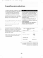
Especificaciones EI6ctricas
.....................................
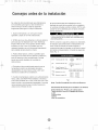
Consejos Antes dela Instalaci6n
..................................
18
18-19
20
21
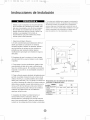
Instrucciones de Instalaci6n
..................................
22-24
Instrucciones de Operaci6n
..................................
25-28
.......................................
29
Cuidado y Mantenimiento
Guia para la Soluci6n de Problemas ...............................
30
Garantia ....................................................
31
WAC
5
6
8
USER
MAN
final
3/2/05
12:23
PM
Page
4Q
INTRODUCTION
Thank you for choosing
provides
If properly
instaflation
instaflation
information
maintained,
this room air conditioner
necessary
to cool your home. This USE AND CARE MANUAL
for the proper care and maintenance
your air conditioner
difficulties, read instructions completely before starting.
and operation of your room air conditioner.
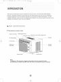
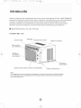
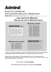
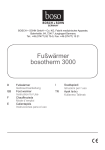
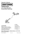
Mechanicam
control
Interior Air Outlet
of your new room air conditioner.
will give you many years of trouble free operation.
To avoid
This manual contains information
for the
modem
al Air Vane
Vertical Air Vane
Fresh Air Lever (for 8K model only)
Cabinet
Air Filter(Inside)
Front Panel
interior Air
inlet Grille
Exterior
Air Inlet
Control Knob
Power Cord
Note:
The figures in this manual are based on the external view of a standard model,
Consequently,
the shape may differ from that of the air conditioner
you have selected,
WAC
5
6
8
USER
MAN
final
3/2/05
12:23
PM
Page
50
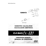
INTRODUCTION
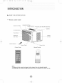
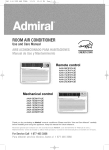
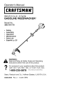
_,- Remote
control
model
)ntal Air Vane
Interior
Air Outlet
Vertical
Air Vane
Fresh Air Lever
(for 8K model
only)
Cabinet
Air Filter(Inside)
Front Panel
o
Interior Air
Inlet Grille
Remote
Exterior
Air Inlet
Control
Control
Control Panel
Panel
_-
Power
Remote
Cord
Control
Note:
The figures
in this manual
are based on the external
view of a standard
model.
Consequently,
the shape may differ from that of the air conditioner
you have selected.
WAC
5
6
8
USER
MAN
final
3/2/05
12:23
PH
Page
6Q
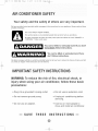
AiR CONDiTiONER SAFETY
Your safety and the safety of others are very important.
We have provided many important safety messages in this manual and on your appliance. Always read and obey
all safety messages.
This is the SAFETY ALERT SYMBOL.
This symbol alerts you to potential hazards that can kill or hurt you and others.
All safety messages will follow the safety alert symbol and either the word "DANGER" or
"WARNING." These words mean:
You can be killed
immediately
follow
or seriously
inured if you don't
instructions.
You can be killed or seriously
don't follow instructions.
inured if you
All safety messages will tell you what the potential hazard is, tell you how to reduce the chance of injury, and tell
you what can happen if the instructions are not followed.
! IVlPORTANTSAFETYiNSTRUCTIONS
WARNING:To reduce the risk of fire, electrical shock, or
injury when using your air conditioner, follow these basic
precautions:
• Plug into a grounded
• Do not remove
ground
3-prong
outlet.
prong.
Do not use an adapter.
m
SAVE
Do not use an extension
Unplug air conditioning
servicing.
cord.
before
Use two or more people to
move and install air conditioner.
THESE
INSTRUCTIONS
WAC
5
6
8
USER
MAN
final
3/2/05
12:23
PH
Page
7 0
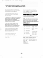
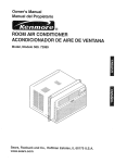
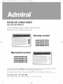
INSTALLATIONREQUIREMENTS
The portable air conditioner should be connected
to a 115 V, 60 Hz, 15- or 20-amp fused 3-prong
grounded outlet.
Power Supply
NOTE:
o
o
The use of a time-delay fuse or time-delay
breaker is recommended.
Your
unit's
Cord
device
may differ
from
the one shown.
circuit
B
All wiring must comply with local and national
electrical codes and be installed by a qualified
electrician. If you have any questions, contact
a qualified electrician.
A Reset
ELECTRIC SHOCK HAZARD
Plug into a grounded 3-prong outlet.
Do not remove ground prong.
Do not use an adapter.
•
DO
not
use
an
extension cord.
• Failure to follow these instructions can
result in death, fire, or electrical shock.
|
|
|
|
|
|
|
|
Button
B Test Button
This room air conditioner is equipped with a power supply cord required
by UL This power supply cord contains state-of-the-art
electronics that
sense leakage current. If the cord is crushed, the electronics detect leakage
current and power will be disconnected in a fraction of a second.
To test your power supply cord:
1. Plug power supply cord into a grounded
2. Press RESET.
3-prong
outlet.
3. Press TEST (listen for click; Reset button will trip and pop out).
4. Press and release RESET (listen for click; Reset button will latch
and remain in).The power supply cord is ready for operation.
NOTES:
• The Reset button
must be pushed in for proper operation.
• The power supply cord must be replaced if it fails to trip when the
test button is pressed or fails to rest,
• Do not use the power supply cord as as an off/on switch, The
power supply cord is designed
• A damaged
as a protective
device,
power supply cord must be replaced with a new power
supply cord obtained
be repaired.
from the product manufacturer
• The power supply cord contains no use serviceable
_mmmmmmmml_
the tamper-resistant
and must not
parts, Opening
case voids all warranty and performance
claims.
INSTALLAT! !N INSTRUCTION
Remove
EXCESSIVE WEIGHT HAZARD
I
Use
twoairorconditioner.
more people to move and
install
I
Failure
to do so can result in back or
other
injury.
I
L ,,,, .,, .,, .,, ,,,, ,,,, ,,,, ,,,, .i
packaging
materials
= Remove and properly dispose of packaging materials.
Remove tape and glue residue from surfaces before
turning on the air conditioner. Rub a small amount
of liquid dish soap over the adhesive with your fingers.
Wipe with warm water and dry.
Do not use sharp instruments, rubbing alcohol,
flammable fluids, or abrasive cleaners to remove
tape or glue. These products can damage the
surface of your air conditioner.
Handle air conditioner
with care.
WAC
5
6
8
USER
MAN
f_nal
3/2/05
12:23
PM
Page
80
ELECTRICALSPECIFICATIONS
1. All wiring
electrical
must comply with local and national
codes and must be installed
licensed electrician.
by a
Once you have any
questions regarding the following
contact a licensed electrician.
If the air conditioner
has a serial plate rating
of 115 volts and up to and including
7.5 amps
the unit maybe on a fuse or circuit breaker
with other devices.
However,
the maximum
amps of all devices on that fuse or circuit
breaker can not exceed the amps of the fuse
of circuit breaker.
instructions,
2. Check available power supply and resolve any
wiring problems BEFORE installing and operating
this unit.
3. For your safety and protection,
this unit is
grounded
when
plugged
through the power cord
into a matching
wall outlet.
If the air conditioner
has a serial plate rating
of 115 volts and greater than 7.5 amps it
must have its own fuse or circuit breaker,
and no other device or unit should be
operated
on the fuse or circuit breaker.
If you are
not sure whether your wall outlet is properly
grounded,
please consult a licensed
electrician.
4. The wall outlet(3-pin) must match the plug
(3-pin) on the power cord supplied with the unit.
DO NOT use plug adapters
or extension
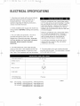
See (Table 1) for receptacle
and fuse information.
COOLING
RATED
CAPACITY
cords.
To avoid the possibility
disconnect
the power
installing or servicing.
5. The rating plate on the unit contains electrical
and other technical data. The rating plate is located
on the right side of the unit.
5K,
VOLTS
of personal injury,
to the unit before
6K.
8K
125
AMPS
15
WALL OUTLET
FUSE
SIZE
15
Time Delay Fuse
(or circuit breaker)
Plug type
Table 1
Note:
5K including
6K including
8K including
AAW-05CR1FHU
AAW-06CR1FHU
AAW-08CR1FHU
AAW-08CM 1FHU
AAW-05CM1FHU
AAW-06CM1FHU
AAW-08DR1FHU
AAW-08DM 1FHU
WAC
5
6
8
USER
MAN
final
3/2/05
12:23
PH
Page
90
TiPS BEFOREiNSTALLATiON
Your RoomAir Conditioner unit is designed to
be highly efficient and save energy. Follow these
Your RoomAir Conditioner was designed
for easy installation in a single or double-hung
recommendations
window. NOTE: This unit is NOT designed for
vertical (slider type) windows.
for greater efficiency.
1. Select thermostat setting that suits your
comfort needs and leave the thermostat at
that chosen setting.
To avoid installation/operating
difficulties,
read the instructions
thoroughly.
2. The air filter is very efficient in removing airborne
particles. Keep the air filter clean. Typically, filter
should be cleaned once a month. More
frequent cleaning
P'!'I
may be necessary depending
NOTE:
Save the shipping carton and packing
materials for future storage or transport of the unit.
Please check the contents of the hardware kit
on outdoor and indoor air quality.
against the corresponding
installation of the unit.
3. Use drapes, curtains, or shades to keep
See lists below. (Fig. 1)
direct sunlight from heating your room, but
DO NOT obstruct the air conditioner. Allow air to
circulate around the unit without obstructions.
(_s_>
4. Start your air conditioner before outdoor
air becomes hot and uncomfortable. This
avoids an initial period of discomfort
the unit is cooling off the room.
while
model check list, prior to
3/4"Screws (12)
Seal(l)
2/5"Screws (8)
(_
1_
Top Channel(1 )
factory installed
Side Curtain RH(1)
Side Curtain LH(1)
L Bracket(2)
5. When outdoor temperature
is cool
enough, use HIGH or LOW FAN
only. This circulates indoor air, providing
Side Bracket(2)
Fig.1
some cooling comfort, and utilizes less
electricity than when operating on a
cooling setting.
Foam(1
NOTE: Surplus
screw(s)
for spare use,
Tools Needed for Window Installation
Screw drivers:
Both Philips and flat head
Power drill:
1/8 inch diameter drill bit
Pencil
Measuring tape
Scissors
Carpenters level
)
WAC
5
6
8
USER
MAN
final
3/2/05
12:23
PM
Page
1_
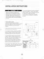
iNSTALLATiONiNSTRUCTiONS
F. Your unit was designed to evaporate condensation
under normal conditions. However, under extreme
Because the compressor is located on the
controls side of the unit (right side), this side
will be heavier and more awkward to manipulate.
Inadequate support on control side of the unit
can result in personal injury and damage to your
unit and property. Therefore, it is recommended
to have someone assist you during the installation
of this unit.
humidity conditions,
excess condensation
may cause
the base pan to overflow to the outside.
The unit should be installed where condensation
run-off cannot drip on pedestrians
properties.
or neighboring
1. Select the Best Location
A. Your room air conditioner
was designed to
/
Awning
fit easily into a single or double hung window. However
since window designs vary, it may be necessary to
make some modifications
installation.
for safe and proper
B. Make sure the window
and frame are structurally
sound and free from dry, rotted wood.
C. For maximum
efficiency,
install the air conditioner
on side of the house or building which favors more
shade than sunlight. If the unit is in direct sunlight,
it is advisable to provide an awning over the unit.
Side
D. Provide sufficient clearance
Fence,
wall, or
other
30" Min.
around the cabinet
to allow for ample air circulation through the unit,
obstruction
obstacle.i
Ground
See (Fig.2). The rear of the unit should be outdoors
and not in a garage nor inside of a building,
Keep unit as far away as possible from obstacles
and obstructions and at least 30" above the floor or
ground, Curtains and other objects within a room
should be prevented from blocking the air flow,
_
Fig.2
Window opening requirements
(see table below)
5K-6K
E. Be certain the proper electrical
outlet is within reach
of the installation. Use only a single outlet circuit rated
at 15 amps. All wiring should be in accordance with
local and national electrical codes.
Cabinet size
(W*H*D)
Min. Window
opening
Max. Window
opening
8K
17.7" "12.4" "15.7" 18.5" "13.7" "17.7"
21"
22"
35"
36"
WAC
5
6
8
USER
MAN
final
3/2/05
12:23
PM
Page
i s
iNSTALLATiONiNSTRUCTiONS
_W P_I96_IW
_'_":'_'__,*'"_
_,,_fs_
(}B _::_1::'_
_:_
1. If your air conditioner cabinet 18" wide, it will fit
window openings 21" to 32" in wide. Minimum
opening height is 14" from bottom of sash to sill
(Fig. 1 ).
Fig. 1
2. Insert the guide panels into the guides of the air
conditioner. Fasten the curtains to the unit with screws
(Fig. 2).
2/5 " Screws
Fig.
2
3. Cut the adhesive-backed seal strip the window width.
Remove the backing from the seal strip and attach
the seal strip to the underside of the bottom window.
(Fig. 3)
Fig. 3
4. Measure the inside window sill width and find
the center line as shown in Fig. 4.
Fig.
4
WAC
5
6
8
USER
MAN
final
3/2/05
12:23
PM
Page
1_
iNSTALLATiONiNSTRUCTiONS
5. Install the L brackets on the outer sill with the
Outer
inner
SIll
SIll
short side of the bracket against the back of the
inner sill. Install one L bracket 7.5" to each side
of center line. See Fig• 5.
Short
Side
./'"
6. Carefully lift the air conditioner and slide it into
Fig. 5
the open window. Make sure the bottom guide of
the air conditioner drops into the notches of the L
brackets• When the air conditioner drops into the L
brackets, the air conditioner will be centered in window
opening as show in Fig. 6.
While steadying the air conditioner, carefully bring
the window sash down behind the top channel
of the air conditioner, as shown in Fig. 7.
First, fix both sides onto the window sill with two 3/4"
screws and one 215" screw ( which is unscrewed from
each side of the unit). Then fix top channel to widow
sash with one 3/4" screw and fix side curtain frames
with four 3/4" screws as shown in Fig.6.
Fig. 6
7. If storm window
presents interference, fasten a
2" wide wood strip to the inner window sill across
the full width of the sill. The wood strip should be thick
enough to raise the height of the window sill so that
the unit can be installed without interference from the
storm window frame, as show in Fig. 8.
Top of wood strip should be approximately 3/4" higher
than the storm window frame to help condensation to
drain properly to the outside.
Install a second wood strip (approximately 6" long by
11/2"wide and same thickness as first strip) in the center
of the outer sill flush against the back of the inner sill.
Screw the L brackets into this strip.
This will raise the L bracket as shown in Fig. 8.
Fig.7
3/4"Clearance
S,or,,L,10ow
,,l&,,,
¢'
Fig .8
.......
WAC
5
6
8
USER
MAN
final
3/2/05
12:23
PM
Page
i_
OPERATINGiNSTRUCTiONS
_Mechanicam
control
model
MODE
The mode knob controls fan speeds and cooling
speeds. To set desired cooling temperature, simply
OFF
rotate the mode knob dial to the appropriate
setting. See Fig. 9.
Thermostat
THERMOSTAT
The thermostat
automatically
cycle (compressor)
room temperature.
kno<
Mode knob
controls the cooling
of the air conditioner to maintain
However, the fan motor will
continue to operate after the compressor
cycle) is completed. See Fig.9.
(cooling
Fig.9
LOW FAN will circulate the air at a minimum speed
without cooling.
HIGH FAN will circulate the air at a maximum speed
without cooling.
LOW COOL provides cooling, automatically
minimum air circulation.
time use.
Recommended
P'_'I
[o,7,:,_!jui[o]_
for night-
When using FAN control,
turn slowly allowing
unit
to adjust.
When using THERMOSTAT,
HIGH COOL provides cooling, automatically with
quick cooling or for extremely hot days. Once room
is cooled, reduce setting to LOW COOL.
OFF will completely
IV_y
with
be sure to allow three
minutes before changing temperature.
Adjusting
too quickly may cause an overload resulting in a
blown fuse.
shut-off the unit.
NOTE: After setting the mode, allow 3
minutes before switching to another mode.
Fresh Air Ventilation
is usually kept in the closed
position. Use only when clearing smoke and/or
odors from the room. Pull to open. (See Fig.10).
Fresh Air
Vent Lever
Fig.10
WAC
5
6
8
USER
MAN
final
3/2/05
12:23
PM
Page
i_
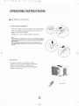
OPERATINGiNSTRUCTiONS
You can easily operate this air conditioner
by pressing
relevant
button on the control pane[ as we[[ as the remote control
Control Panel
(_) Button
The air conditioner will be started when it is energized or will
be stopped when it is in operation, if you press this button.
When the air conditioner is heating, allow 3 minutes after you
press this button.
Mode button
Each time
Mode button is pressed,
the operation
mode is changed in sequence:
5K, 6K, 8K cooling only: COOLING
FAN ONLY
ENERGY SAVING
COOLING
8K with heater
COOLING
FAN ONLY
HEATING
ENERGY
SAVING
COOLING
NOTE: After setting the mode, allow three (3) minutes before
switching to another mode. In the FAN ONLY Mode, Room
Temperature display range is from O°C (32°F) to 380C (99°F).
Room Temperature below 32°F, the Temperature display LO.
Room Temperature above 99°F, the Temperature display HI.
Fan Speed
button
Used to select fan speed in sequence
auto, low, medium
and high (low and medium are in same fan speed).
Timer
button
indication
_
Used to set or cancel
Auto fan speed
_
Cooling
Low fan speed
,_
Fan only
is set, the time LED displays
,_
Medium fan speed
"]_" Heating
High fan speed
42: Energy-saving
If the ON TIMER is set, the timer LED displays
remaining time to turn on the unit. If you want
•
•
press TIMER
panel
:
I--a J--I "F
Cl I"l h
Display set temp
Display
set timer
the
remaining time to turn off the unit for only 12 seconds,
then LED shifts to display set temperature.
If you press
TIMER button within the 12 seconds, OFF TIMER will be
cancelled.
ON TIMER,
of LED on control
timer operation.
When the unit is in operation, you can set OFF TIMER.
When the unit is off, you can set ON TIMER.
Timer setting range is 0 to 24 hours.
If the OFF TIMER
symbols
Timer
Above LED lights on when
the relevant mode is in use.
the
to cancel
button.
Button
Used to set room temperature in COOLING mode or used to set time in TIMER mode.
If the two keys are pressed at the same time, the temperature LED display will alternate between °C and °E
I
NOTE: Temperature
setting
range is from 19°C (66°F) to 31 °C (88°F).
WAC
5
6
8
USER
MAN
final
3/2/05
12:23
PM
Page
i_
OPERATINGiNSTRUCTiONS
0
0
0
0
0
0
Power
BUTTON
The appliance will be started when it is
energized or will be stopped when it is
in operation, if you press this button.
Mode
Mode BUTTON
Used to select the operation mode.
Power Saver
BUTTONS
Used to set room temperature in COOLING
mode or used to set time in Timer mode.
ii
High BUTTON
Used to select the high fan speed
mode.
Mid
BUTTON
Used to select the mid (same as low) fan
speed mode.
LOW BUTTON
Used to select the low fan speed mode.
0
0
0
at once. modes
Wait three
minutes.
,, respond
hen changing
during(3)operation,
Auto BUTTON
Used to select the auto fan speed mode.
Timer BUTTON
Used to set or cancel timer operation.
Power Saver BUTTON
Used to select the Energy-saving mode.
sometimes
,, Wait three (3) minutes before restarting the appliance.
the unit does not always
WAC
5
6
8
USER
MAN
final
3/2/05
12:23
PM
Page
i_
OPERATINGiNSTRUCTiONS
•
How to insert
the Batteries
Remove the battery cover according
to the arrow direction.
Insert new batteries making sure that the (+) and (-) of
battery are matched correctly.
Reattach the cover by sliding it back into position.
Note:
Use 2 LR6 AA(f.Svolt)
Replace batteries
with
becomes
dim.
If the replacement
will keep original
control)
batteries.
new ones
Do not use rechargeable
of the same type when
is done within 1 minute,
presetting.
(This function
batteries.
the display
the remote control
only for LCD remote
• How to Use
To operate the room air conditioner, aim the
remote control to the signal receptor. The remote
control will operate the air conditioner at a
distance of up to 23 feet when pointing at signal
receptor of indoor unit.
Signal
receptor
WAC
5
6
8
USER
MAN
final
3/2/05
12:23
PM
Page
i_
CAREAND MAINTENANCE
When servicing
the air conditioner,
be sure to
turn the mode switch to the "OFF" position and
disconnect the power cord from the electrical outlet.
1. DO NOT use gasoline, benzine, thinner or
other chemicals on the air conditioner as these
substances
may cause damage
and deformation
to the paint finish
of plastic parts.
DO NOT forget to install the air filter. If the air
conditioner is left to operate without the air filter,
dust is not removed from the room and may
cause your air conditioner to fail.
When the air filter inlet grill and cabinet are dirty,
wipe with lukewarm water (below 104°F).Use of
mild detergent is recommended.
2. Never attempt to pour water directly in front
of the unit as this will cause deterioration of
the electrical insulation.
Cleaning
the Air Filter
Cleaning
of Air Filter
If the air filter becomes clogged with dust, air-flow
1. Remove
is obstructed and reduces efficiency. The air filter
should be cleaned once a month. More frequent
tapping it or vacuum clean it.
cleaning
40°C (104 °F) while rubbing
may be necessary
depending
on outdoor
and indoor air quality.
2. Wash the filter well with lukewarm
water below
lightly. To get better
results, wash it with soapy water or a neutral
cleaning
Air Filter Removal
dust clogged in the filter by
agent.
3. Rinse the filter well using clean water then
The air filter on the above models is located
dry completely.
behind the air intake front grill.
End-of-Season
To remove the air filter, grasp the filter handle(tab)
1. Operate the fan alone for half a day to dry out
the inside of the unit.
located on the up (center) side of the air inlet grille
and slide the air filter to the up.
To reinstall the air filter, reverse the above
procedure.
Care
2. Turn off power and remove
3. Clean filter.
4. Store in a dry location.
plug from wall socket.
WAC
5
6
8
USER
MAN
final
3/2/05
12:23
PM
Page
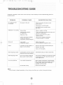
TROUBLESHOOTING
1_
GUIDE
Frequently, a problem is minor and a service call may not be necessary, use this troubleshooting
possible solution.
PROBLEM
Air conditioner
not operate
POSSIBLE
will
CAUSE
SUGGESTED
No power to the unit.
Check connection
power source.
guide for a
SOLUTION
of power cord to
Check fuse or circuit breaker.
Set MODE knob to position
than "OFF".
Inefficient or no cooling
other
Dirty air filter.
Clean or replace
Inappropriate capacity
for application.
Check with dealer to determine
capacity for application.
air filter.
Blocked air flow.
Remove obstruction
outdoor louvers.
Power interruption, settings
change too quickly, or
compressor overload tripped.
Let fan run to restart compressor
(in approximately
10 minutes).
Noisy unit
Loose parts.
Inadequate support.
Tighten loose parts.
Provide additional support to unit.
Odors
Formation of mold, mildew, or
algae on wet surfaces.
Remove drain plug and drain base pan.
proper unit
from grill or
Replace drain plug.
Clean unit thoroughly.
Water dripping
outside
Condensation run-off is normal
during hot and humid weather
Add flexible tubing to redirect water flow.
Water dripping
inside
Unit is not properly angled to
allow water to drain outside,
Unit must be installed on an angle for proper
condensation
run-off. Check the unit and
make adjustments.
Low outside temperature.
When outdoor
65°F or below,
cooling mode.
operation until
Unit air filter is dirty.
Remove and clean filter.
Ice or frost build-up
temperature is approximately
frost may form when unit is in
Switch unit to FAN (only)
frost melts.
NOTE:
If circuit breaker
is tripped
repeatedly,
or fuse is blown
more
than once, contact
a ficensed
technician.
WAC
5
6
8
USER
MAN
final
3/2/05
12:23
PM
Page
1_
WARRANTY
5 YEAR
FULL
WARRANTY
This product
is warranted
for 5years
from the date of original
purchase.
Any part
which fails in materials
or workmanship
will be replaced
within the warranty
period.
This warranty
covers in home service.
Acopy
of your proof of purchase,
with date of
purchase
and product
name included,
is required
to arrange
this service
repair.
For the name and location
of an authorized
service
provider
nearest
you, please
CALL 1-877-465-3566.
Please
reference
product
name,
brand name,
and model
number when you call.
This warranty
does not apply if the damage
occurs
because
handling
or operation,
shipping
damage,
abuse,
misuse,
made or attempted,
or the use of the product
for commercial
for which it was not intended.
of accident,
improper
unauthorized
repairs
use, or any other use
ALL WARRANTIES,
EXPRESSED
OR IMPLIED,
LAST FOR 5 YEARS
FROM THE
DATE
OF ORIGINAL
PURCHASE.
THIS
WARRANTY
DOES
NOT
COVER
LIABILITY
FOR
INCIDENTAL
OR
CONSEQUENTIAL
DAMAGES
FOR
ANY
CAUSE
WHATSOEVER.
This warranty
is extended
to the original
owner and any succeeding
owner for
products
purchased
for home use within the USA.
Some states
do not allow the
exclusion
or limitation
of incidental
or consequential
damages.
This
warranty
gives you specific
rights, and you may also have other rights which may vary from
state to state.
To know what your legal rights
are, consult
your local or state
consumer
affairs
office
or your
state's
Attorney
General.
WAC
5
6
8
USER
MAN
final
3/2/05
12:23
PM
Page
20
lntr0ducci6n
Gracias por elegir este aire acondicionado para enfriar su hogar. Este MANUAL DE USO Y MANTENIMIENTO
proporciona la informaciOn necesaria para cuidar y mantener en forma adecuada su nuevo aire acondicionado.
Funcionar(] sin problemas durante muchos afios si le brinda el mantenimiento apropiado. Para evitar
problemas
al instalarlo, lea completamente
informaci(}n acerca de la instalacion
Modeio
Mec
antes de comenzar.
del aire acondicionado
Este manual contiene
para habitaciones.
nico
Gabinete
Panel
las instrucciones
y el funcionamiento
Frontal
de Aire Vertical
Tirador
Controlado
Filtro deAire
(en el interior
Rejilla de
Entrada de
Aire
Entrada de
Aire Exterior
Palanca
de Aire Fresco
(s(_lo en el modelo
Nota:
Las im(_genes deeste manualestan
En consecuencia,
es probableque
que usted seleccion6.
8K)
Cable
de Alimentaci6n
basadas en la vista externa de un modelo estdndar.
la forma sea diferente a la del aire acondicionado
WAC
5
6
8
USER
MAN
final
3/2/05
12:24
PM
Page
20
lntr0ducci6n
D, Modemo de Remoto
contromador
Entrada de
Aire Inter*ar
Aleta
deAire
Horizontal
AireVertical
PalancadeAireFresco(s01oenelmodelo8K)
Gabinete
Filtro deAire
(en el interior
Panel
Rejilla
de
Entrada
de
Aire Interior
Control
Remoto
Panel de Control
j"
Cable
Panel de Control
Entrada de
Aire Exterior
de Alimentaci0n
Control
Remoto
<
Nota:
Las im0genes
de este manualestdn
En consecuencia,
es probable
que
que
usted
seleccionO.
basadasen
lavista
externa
de un modelo
est0ndar.
la forma
sea diferente
ala delaire
acondicionado
WAC
5
6
8
USER
MAN
final
3/2/05
12:24
PM
Page
2_
Especificaciones el6ctricas
1. Todos los cables deben cumplir con los c6digos
el6ctricos locales y nacionales y los debe instalar
un electricista licenciado. Si tiene preguntas
relacionadas
con las siguientes
comuniquese
2. Verifique
con un electricista
el suministro
resuelva cualquier
instrucciones,
licenciado.
de energi a disponible
problema
de instalar y hacer funcionar
y
con los cables ANTES
esta unidad.
3. Para su seguridad y protecci6n, esta unidad est6
conectada a tierra a trav6s del cable de alimentaci6n
cuando se Io enchufa
a un tomacorriente
de pared
Para evitar lesiones fisicas,
desconecte
suministro
de energfa
de la unidad
antes de instalarla o repararla.
provisto de conexi6n a tierra. Si no estd seguro de
que el tomacorriente
de pared cuenta con la
conexi6n a tierra apropiada,
electricista licenciado.
4. El tomacorriente
consulte
Consulte
de pared (de 3 clavijas)
de enchufe
debe
ni cables de extensi6n.
la Tabla 1 para obtener informaci6n
de receptciculos
el
con un
coincidir con el enchufe (de 3 clavijas) del cable de
alimentaci6n suministrado con la unidad. NO utilice
adaptadores
Si el r6tulo del aire acondicionado
indica 115
voltios y hasta 7.5 amperios,
la unidad se
puede conectar a un cortacircuito
o fusible
utilizado por otros dispositivos.
No obstante,
la suma de los amperios
maximos de todos
los dispositivos
conectados
a dicho
cortacircuito
o fusible no deben exceder los
amperios
del mismo.
Si el r6tulo del aire acondicionado
indica 115
voltios y m6s de 7.5 amperios, debe tener su
propio fusible o cortacircuito y no se debe@
conectar ningan otro dispositivo o unidad a dicho
fusible o cortacircuito.
Tipos
de
Capacidad
Receptdculos
5K, 6K, 8K
y Fusibles
de Voltios
125
acerca
Amperios
y fusibles.
5. El r6tulo de la unidad contiene datos el6ctricos
t6cnicos. Dicho r6tulo se encuentra en el lade
derecho de la unidad.
y
Tomacorriente
15
de Pared
Tama_o del Fusible
15
Fusible con Retardo
(o Cortacircuito)
Tipo de enchufe
Tabla
Nota: 5K incluido
6K incluido
8K incluido
1
AAW-05CR1FHU
AAW-06CR1FHU
AAW-08CR1FHU
AAW-08CM1FHU
AAW-05CM1FHU
AAW-06CM1FHU
AAW-08DR1FHU
AAW-08DM1FHU
WAC
5
6
8
USER
MAN
final
3/2/05
12:24
PM
Page
20
C0nsej0s antes de la instalaci6n
Su unidad de AireAcondicionado
para Habitaciones
se ha disen_ado para Iograr un alto rendimiento y
ahorrar energ_a electrica. Siga las siguientes
sugerencias para Iograr un mayor rendimiento.
El AireAcondicionado
dise_ado
en ventanas
unidad
para Habitaciones
de modo
se ha
tal que resulte facil su instalaci6n
armadas
sencillas
NO se ha dise_ado
o dobles.
NOTA:
para ventanas
esta
verticales
(de tipo deslizante).
I. Ajuste
el termostato
agradable
y d_jelo
a un nivel que le resulte
en el nivel seleccionado.
las instrucciones.
2. El filtro de aire es muy eficiente a la hora de eliminar
particulas que se desplazan por el aire. Mantenga
limpio el filtro de aire. Pot Io general, el filtro deber_
limpiarse una vez al mes. Es probable que sea
necesario limpiarlo con m_'_sfrecuencia dependiendo
de la calidad del aire exterior o interior.
NOTA:
conserve
la caja de la unidad
de empaque
para almacenarla
futuro.
de instalar
Antes
contenido
del juego
la unidad
de herrajes
del modelo
correspondiente.
listas
1).
(Fig.
y los materiales
o transportarla
compare
en el
el
con la lista de control
Consulte
las siguientes
3. Puede utilizar tapices, cortinas o pantallas para
evitar que la luz directa del sol caliente su habitaci6n,
pero NO obstruya el aire acondicionado. Permita
que el aire circule alrededor de la unidad sin
obstrucciones.
Tornillos de 3/4" (12)
(_)
Tornillos de 2/5" (8)
4. Encienda
el aire acondicionado
temperatura
exterior
desagradable.
mientras
De esta manera
la unidad
antes de que la
sea demasiado
enfrfa
elevada
evitar6
sufrir
y
[_
Sello (1)
Espuma (1)
Canal Superior (1)
instalado en la f6brica Cortina Lateral Derecha (1)
calor
la habitaci6n.
5. Cuando la temperatura exterior es Io suficientemente
fresca, utilice s61o HIGH FAN (ventilador al m_iximo) o
LOW FAN (ventilador al m_nimo). Esto hace que el aire
interior circule a una temperatura agradable y consume
menos energia ebctrica que si hiciera funcionar la
unidad como enfriador de aire.
_
Soporte en L (2)
_,_
SoporteLateral(2)
Cortina Lateral Izquierda (1
_]_
_
Fig.1
Nota: Tornillo
Excedente
Para d Uso de Reserva.
Herramientas Necesarias para la Instalaci6n en Ventana:
Destorni!ladores: Philips y de cabeza plana
Taladro electrico: broca de 1/8 pulgada de dkimetro
L_piz
Cinta m6trica
Tijeras
Nivel de carpintero
WAC
5
6
8
USER
MAN
final
3/2/05
12:24
PM
Page
20
lnstrucciones de Instalaci6n
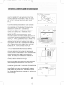
F. La unidad est6 dise_ada para evaporar
bajo condiciones
Debido
a que el compresor
de los controles
se encuentra
(a la derecha
No obstante,
la condensaci6n
bajo condiciones
de extrema humedad, es probable que la condensaci6n
del lado
de la unidad),
normales.
excesiva haga que la bandeja base se desborde
este
hacia el
lado ser6 mas pesado y m_s dificil de manipular.
Si la unidad no se sostiene
bien de dicho lado
exterior. Por Io tanto la unidad deber6 instalarse en un lugar
donde la descarga de la condensaci6n no gotee sobre el
pueden
paso de peatones ni en las propiedades
producirse
lesiones
fisicas
y da_os
a la
vecinas.
unidad y a su propiedad.
Pot Io tanto, le
recomendamos
que para instalar esta unidad
solicite
ayuda
I. Seleccione
a otras
la Mejor
personas.
Ubicaci6n
A. El aire acondicionado
dise_o
que facilita
armadas
sencillas
que los diseRos
probable
para habitaciones
su colocaci6n
o dobles.
No obstante,
de ventana
para Iograr
un
Toldo
/
debido
son tan variados,
que sea necesario
modificaciones
tiene
en ventanas
realizar
a
es
algunas
una instalaci6n
segura
y
adecuada.
B. Asegarese de que la ventana y el marco tengan
una estructura firme y que la madera no este rajada
ni podrida.
C. Para Iograr el m_ximo rendimiento,
instale el aire
acondicionado
del lado de la casa o edificio donde
haya mcis sombra
que sol. Si la unidad
"_--_X
se encontrara
expuesta
a la luz del sol, es aconsejable
toldo encima.
colocarle
Cerca,
X
Obstrucci6n
30" Min.
pared u
otro
un
lateral
_
obstdculo.i
Suelo
D. Deje suficiente
espacio
alrededor
circulacidn
del gabinete
permitir
una amplia
unidad.
Vea (Fig. 2). La parte
de aire a trav6s
deber6
dar al aire libre y no a un garaje
posterior
para
de la
Fig.2
de la unidad
ni al interior
de
Requisitos
para las aberturas
de ventanas
un edificio. Mantenga la unidad Io md_slejos posible de (consulte
la siguiente
tabla)
obst_culos que puedan causar obstrucciones y por Io
5K,6K
menos a 30" del nivel del piso o del suelo. Deberd_n
TamaRodel gabinete 17.7" '12.4" "15.7"
tomarse precauciones para evitar que las cortinas o
(A*H*L)
cualquier otro objeto dentro de una habitaci6n
obstruyan el flujo de aire.
E. Asegt3rese
tomacorriente
de instalar la unidad cerca de un
el6ctrico adecuado.
Utilice un
tomacorriente
de 15 amperios
para el aire acondicionado.
cumplir
con los c6digos
con circuito
Todos
el_ctricos
exclusivo
los cables
locales
deberdn
y nacionales.
8K
18.5" "13.7" "17.7"
Abertura mf nima
de Ventana
21"
22"
Abertura m_xima
de Ventana
35"
36"
WAC
5
6
8
USER
MAN
final
3/2/05
12:24
PM
Page
2_
lnstrucciones de Instalaci6n
_>__
_
/@ _G_2_iS_
e_
V_¸__
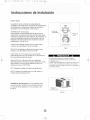
1. Si el aire acondicionado tiene un gabinete de 18"
de ancho, podr(_ colocarse en aberturas de ventanas
de 21"a 32" de ancho. La altura m_nima de abertura
es de 14" desde la parte inferior del marco hasta el
umbral (Fig. 1).
Fig. 1
2. Inserte los paneles gula en las guias del aire
acondicionado. Sujete las cortinas a la unidad con
los tornillos (Fig. 2).
Tornillos
Fig. 2
/
3. Corte la tira de sello adhesivo del ancho de la ventana.
Quite el revestimiento de la tira adhesiva y p6guela en el
interior de la parte inferior de la ventana (Fig. 3).
Fig. 3
4. Mida el ancho del interior del umbral de la ventana y
defina la Hnea central tal como se indica en la Fig. 4.
Fig. 4
de 2/5"
WAC
5
6
8
USER
MAN
final
3/2/05
12:24
PM
Page
20
lnstrucci0nes de Instalaci6n
Umbral
Externo
Tomil]o
modo que la parte mds corta del soporte apoye contra
la parte posterior del umbral interno. Instale un soporte
en L a 7.5" de cada lado de la I[nea central. Vea la
de 3/4" Umbral
Intemo
k
5. Instale los soportes en L en el umbral externo, de
L[nea
./
Cenfral
/ Tomillo
de 3/4"
Lado Corto
det Soporte
Fig. 5.
6. Levante el aire acondicionado con mucho cuidado y
desl[ celo por la ventana abierta. AsegQrese de que la
gu_a inferior del aire acondicionado se inserte en las
Fig.
5
ranuras de los soportes en h Cuando el aire
acondicionado apoye en los soportes en L, quedar_
centrado en la abertura de la ventana tal como se
_pL
indica en la Fig.6.
Mientras acomoda el aire acondicionado, baje el
marco de la ventana con mucho cuidado y apOyelo en el
canal superior del aire acondicionado, tal como se indica
en la Fig. 7. Primero, ajuste ambos lados al umbral de la
ventana con dos tornillos de 3/4" y uno de 2/5" (que se
\
destornilla de cada lado de la unidad). Luego ajuste el
canal superior al marco de la ventana con un tornillo de
3/4" y ajuste los marcos de la cortina lateral con cuatro
tornillos de 3/4", tal como se indica en la Fig. 6.
7. Si una ventana resistente a huracanes interfiere,
adhiera una tabla de madera de 2" de ancho al umbral
Fig.
6
Alrededor
_f
de
5'
Sello
interno de la ventana, a Io largo de todo el ancho del
umbral. La tabla de madera debera ser Io suficientemente
gruesa como para elevar la altura del umbral de la
ventana, de modo que la unidad pueda instalarse sin
que el marco de la ventana resistente a huracanes
interfiera, tal como se indica en la Fig. 8.
Para que sea Litil, la parte superior de la tabla de madera
deber_ estar aproximadamente 3!4" mas arriba que el
marco de la ventana resistente a huracanes para sumidero.
Instale una segunda tabla de madera (de aproximadamente
sopor
Fig.7
Espacio
6" de largo por 1 1/2" de ancho y el mismo grosor de la
primera tabla) en el centro del umbral externo contra la
parte posterior del umbral interno. Atornille los soportes
en L a esta tabla. Esto elevara el soporte en L tal como se
indica en la Fig. 8.
Fig.8
de 3/4 _'
WAC
5
6
8
USER
MAN
final
3/2/05
12:24
PM
Page
2_
lnstrucciones de Instalaci6n
MODE (Modo)
La perilla de modo controla las velocidades de
ventilador y de enfriamiento. Para fijar una temperatura
de enfriamiento, simplemente haga rotar la perilla y
col6quela en el nivel deseado. Vea la Fig. 9.
THERMOSTAT
(Termostato)
El termostato controla automciticamente el ciclo de
enfriamiento (compresor) del aire acondicionado
para
mantener la temperatura del ambiente. No obstante, el
motor del ventilador continuar6 funcionando una vez
finalizado el funcionamiento
del compresor (ciclo de
enfriamiento).
Vea la Fig. 9.
OFF
Perilla de
termostato
Perilla de
modo
LOW FAN (Ventilador al M[nimo) har(_ que el aire
circule a una velocidad minima sin enfriar.
Fig.9
HIGH FAN (Ventilador al MOximo) hard que el aire
circule a una velocidad maxima sin enfriar.
LOW COOL (Frfo Mfnimo) enfr[a el ambiente
autom6ticamente
con una circulaci6n m inima de aire.
Se recomienda durante la noche.
Cuando
HIGH COOL (Fr[o M6ximo) enfria el ambiente
autom6ticamente
de manera r_pida o durante d ias de
calor intenso. Una vez que la habitaci6n est6 fria,
reduzca el nivel a LOW COOL.
OFF (Apagado)
la perilla de control
de aire fresco
se ra a mantener
que la unidad
Cuando utilice THERMOSTAT,
aseg_irese de esperar tres
minutos antes de cambiar la temperatura.
Si la cambia
demasiado
r(_pido es posible que cause una sobrecarga
y
se queme el fusible.
un nivel, espere 3
en la
posici6n cerrado. Usando sOlo para limpiar humos
y/o odores de la habitaci6n, tire a comenzar. Vea
la Fig. 10.
de ventilador,
para permitir
apaga la unidad completamente.
NOTA: Despu6s de seleccionar
minutos antes de pasar a otro.
Ventilaci6n
utilice
h_gala girar lentamente
se adapte al nivel.
Palanca
de Aire Fresco
Fig.10
WAC
5
6
8
USER
MAN
final
3/2/05
12:24
PM
Page
20
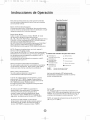
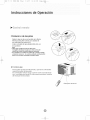
lnstrucci0nes de Operaci6n
Panel de Control
Este aire acondicionado
se puede operar facilmente
con los botones
del panel de control
asicomo
tambien
con el control
remoto.
Bot6n (9 (Encendido/Apagado)
Si presiona
este bot6n, encender_el
aireacondicionado.
Cuando
el aire acondicionado
esta de calefacci6n,
se per
imprentar
este bot6n 3 minutos
despues.
Bot6n Mode (Modo)
Cada vezque
se presiona
el bot6n
MODE,
el modo
de operaci6n
cambia en estas secuencias:
5K, 6K, 8KCOOLINGONLY:
COOLING(Enfriamiento)
FAN ONLY ($61o ventilador)ENERGY
SAVlNG(Ahorro
de Energia)
COOLING(Enfriamiento);
8K WITH HEATER:COOLING(Enfriamiento)FAN
ONLY
(S61o ventilador)H
EATING(Calefacci6n)ENERGY
SAVlNG(Ahorrode
Energia)
COOLING(Enfriamiento).
NOTA: Despu6s
deseleccionar
un nivel, espere
3
minutos
antes de pasara
otro.
Con elmodo
de FAN ONLY, El recinto
dela temperatura
Dehabitaci6n
La temperatura
la temperatura
serd_ Desde
0 °C(32°F)
de la habitaci6n
lucer_ L0.
La temperatura
de la habitacidn
la temperaturalucer6
H1.
hasta
38°C(99°F).
es superior
a32 °F,
essuperior
a 99°F,
Bot6n Fan Speed (Velocidad
del Ventilador)
Se utiliza para seleccionar
la velocidad
del ventilador
en secuencia:autom6tica,
baja, media yalta (baja y
media son dela misma velocidad
de ventilador).
Bot6n Timer (Temporizador)
Se utiliza para programaro
cancelar
funcionamiento
del temporizador.
el
Si mbolos
del indicador
@ Ventflador en
velocidad auto m_'_tica
Ventilador
vetocidad
Ventitador
velocidad
Mostrar
Mostrar
._. Enfriamiento
,_ $61o ventilador
en
baja
en
media
(_
Temporizador
4_: Ahorro
Ventilador en
velocidad alta
I-Ia--I "F
I_1 I--IHR
del panes del control:
de energia
"]_t Calefacci6n
temperatura
fijada
hora programada
Las luces del indicador
LED anteriormente
mencionadas
se encienden
cuando se usan los
modos correspondientes.
Cuando
la unidad
estcien funcionamiento,
puede
seleccionar
OFF TIMER
(Apagar
Temporizador).
Cuando
la unidad
estdapagada,
puede seleccionar
ON TIMER (Encender
Temporizador).
El rangode
horas para programarel
tem porizador
es de0 a 24 horas.
Si selecciona
OFF TIMER,
la pantalla
del
temporizador
indicar6durante
12 se gundos
el tiempo restante
para el apagadode
la
unidad y luego indicarela
temperatura
fijada.
Si presiona
el bot6n TIMERdentro
deesos
12
segundos,
se desactivar61a
funci6n OFF TIMER.
Si selecciona
ON TIMER, la pantalladel
temporizador
indicareel
tiempo restante
para el
encendido
dela unidad.
Si desea cancelar
la
funci6n ON TIMER,
presioneel
bot6n TIMER.
Botdn
•
•
Se utiliza para fijarla
temperaturaambiente
en
modo COOLINGo
para programar
la hora en modo
TIMER.
Sise presionan
las dosteclas
a la vez, el
indicador
de temperatura
alternar_entre°C
y°F.
NOTA:el
(66 °F)y
rangode
temperaturasoscila
31°C (88°F).
entre
19°C
WAC
5
6
8
USER
MAN
final
3/2/05
12:24
PM
Page
20
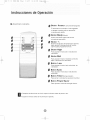
lnstrucciones de 0peraci6n
0
Bot6n
Power
(Encendido/Apagado)
El aparato se encender6
si estd apagado
o apagam cuando estd en operaci6n,
si oprime este bot6n.
0
0
0
0
Bot6n
Mode
(Mode)
Utilice este bot6n para seleccionar
el mode de operaci6n.
0
0
Bot6n
+-
Botones de ajuste de temperatura
oprima
para ajustar la temepratura
del cuarto.
oprima para programar la hora.
Bot6n High
Paraajustarelmodoalta
ventilador.
Bot6n
velocidadde
Mid
Para ajustarel
mode mediana
baja) velocidad
de ventilador.
Bot6n
Low
Para ajustarel
ventilador.
Bot6n
mode baja velocidad
de
Auto
Para ajustarel
ventilador.
Bot6n
(al mismo
modoauto
Timer
Para ponero
velocidad
de
(Temporizador)
cancelarla
operacidn
de timer.
Bot6n Power Saver
Para
o
ajustarel
modode
energia-ahorro.
espues de seleccionar un nivel, espere 3 minutes antes de pasar a otto.
Espere 3 minutes antes de recomenzar el aparato.
WAC
5
6
8
USER
MAN
final
3/2/05
12:24
PM
Page
30
lnstrucciones de Operaci6n
• Colocai6n
de las pilas
Retire la tapa de las en el sentido de la flecha.
Introduzca las pilas nuevas,con cuidado de
que coincidan los polos(+)y(-).
Vuelva a instalar la tapa,desliz('mdola otra vez
a su posici6n.
Nota:
• Utilice pilas 2 LR6 AA(1.5_.No
utiice pilas
recargables.Sustituya
las pilas por otras nuevas del
mismo tipo cuando la pantalla aparezca
atenuada.
• Si la sustituci6n
se reafiza en elplazo
de I minuto, el mando
a distancia
conservar6
los valores prefijados
oridinales(Este
funci6n
es s61o para controlador
remoto
de LCD).
• C c6mo
use
Para operar el aire acondicionado,
apunte el controlador
remoto la se_ar del receptor.
El controladorremoto
se ra aoperar
elaire acondiciondo
con unadiatancia
hasta23 piescuando
apunta a laseSar
del receptor de la unidad.
Receptor
de senal
WAC
5
6
8
USER
MAN
final
3/2/05
12:24
PM
Page
30
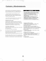
Cuidad0 y Mantenimient0
Cuando repare el aire acondicionado,
aseg_rese
¥!_
de
colocar la perilla de modo en OFF y luego desconectar
el cable de alimentaci6n del tomacorriente electrico.
1. NO utilice gasolina,
productos
quimicos
estas sustancias
y deformar
bencina,
el acabado
ya que
de pintura
las piezas de pl6stico.
agua directamente
unidad ya que dan'arfa
del Filtro
el aislamiento
filtro de aire debera
dependiendo
limpiarlo
de la unidad.
con m_s frecuencia
de la calidad de aire exterior
o interior.
de Aire
anteriormente
mencionados
detr{_s
de la rejilla de entrada
de aire delantera.
tome el mango del filtro (lengt_eta) ubicado
la parte superior (centro) de la rejilla de entrada
deslicelo hacia arriba. Para volver a
instalarlo
El
una vez al mes. Es probable
El filtro de aire de los modelos
Para quitarlo
el6ctrico.
con polvo, el flujo de aire
limpiarse
C6mo Quitar el Filtro
se encuentra
en el frente de la
y reduce el rendimiento
que sea necesario
realice los procedimientos
anteriores
en
a la inversa.
sin el filtro de aire, el polvo no se puede eliminar
la habitaci6n
yes
Limpieza del Filtro de Aire
1. Elimine el polvo acumulado en el filtro. Para
ello aplf quele unos golpes suaves o una
aspiradora dom6stica.
2. Lave bien el filtro con agua templada, de
temperatura inferior a los 40°C (104°F), mientras
Io frota suavemente. Para obtener mejores resultados,
I_velo con agua ]abonosa o con un producto de
limpieza neutro.
3. Enjuague bien el filtro con agua limpia y luego
s6quelo completamente.
de aire y
NO olvide instalar el filtro de aire. Si el aire acondicionado
funciona
instalar el filtro de aire. Si el aire
de Aire
Si el filtro de aire se obstruye
queda obstruido
r'!_
acondicionado
funciona sin el filtro de aire,
el polvo no se puede etiminar de la
habitacbn y es posible que la unidad se
descomponga.
Cuando la rejilla de entrada de aire y el
gabinete est_n sucios, Ii mpielos con agua
templada (por deba] de los 104 °F). Se
recomienda
el uso de un detergente suave.
u otros
en el aire acondicionado,
pueden dar_r
2. Nunca derrame
Limpieza
disolvente
NO olvide
[o]5_lJiiI[e]_
posible que la unidad se descomponga.
de
Cuidado de Fin de Temporada
1. Haga funcionar el ventilador durante medio d[a
para que se seque el interior de la unidad.
2. Ap6guelo y desenchafelo del tomacorriente de
pared.
3. Limpie el filtro.
4. AImac6nelo en un lugar seco.
WAC
5
6
8
USER
MAN
final
3/2/05
12:24
PM
Page
30
Gua para la S01uci6n de Pr0blemas
Generalmente
los problemas son sencillos
Esta guia puedeayudarlo
a resolverlos.
PROBLEMA
CAUSA
El aire acondicionado
no funciona
La unidad
suministro
yes probableque
no sea necesariollamar
POSlBLE
SOLUCI6N
no recibe
el6ctrico.
a un tecnico.
SUGERIDA
Verifique
si el cable de alimentaci6n
st6conectado
al tomacorriente.
e
Verifique
el fusible o el cortacircuito.
Fije el FAN CONTROL (control del
ventilador)
en una posici6n que no sea
OFF.
Enfrfa
poco o nada
Filtro
de aire sucio.
Limpie
Flujo de aire obstruido.
Corte de energ_a el6ctrica,
se cambi6de
nivel
demasiado
rapido o se
dispar6el interruptor
por
sobrecarga
del compresor.
ruidosa
Piezas sueltas.
Soporte inadecuado.
Olores
Gotea
Gotea
Formaci6ndemohou
sobre las superficies
h_medas.
agua
agua
Se forma
escarcha
afuera
adentro
hielo
o
Baja temperatura
Quite toda obstrucci6n
de la rejlla
las persianas
exteriores.
hongos
inclina
el
exterior.
a la unidad.
Quite eltap6ndedrenajeyla
bandeja
base.
Cambie el tapSn de drenaje.
Limpie la unidad en forma completa.
Utilice
flujo
tuberfas
flexibles
para
desviar
el
de agua.
La unidad debe instalarse
con un ligero
desnivel
para permitir
una descarga
adecuada
de la condensacidn.
Verifique
la unidad y realice los ajustes
necesarios.
Cuando la temperatura
exterior sea inferior
los 65°F es posible que se forme escarcha
la unidad funciona
en modo de enfriamiento.
Cambie
el funcionamiento
(solamente)
El filtro de aire de la Lnidad
est6sucio.
o de
Haga funcionar
el ventilador
para
reiniciar
el compresor
(en
aproximadamente
10 minutos).
Ajuste las piezas sueltas.
Proporcione
soporte adicional
Es normal la descarga
de
condensaci6n
cuando el
clima es _lido y hQmedo.
La unidad no est6bien
da como para permitir
desagtte externo.
el filtro de aire.
Hable con el representante
para
determinar
cudl es la capacidad
adecuada
para la aplicacidn.
Capacidad
inadecuada
para la aplicaci6n.
Unidad
o reemplace
Quite
elfiltro
de la unidad
hasta que la escarcha
a
si
a FAN
se derrita.
ylimpielo.
NOTA:
Si el cortacircuito interrumpe la corriente varias veces o el fusible se quema mds de una vez, comunfquese
con un t6cnico licenciado.
WAC
5
6
8
USER
MAN
final
3/2/05
12:24
PM
Page
30
Garantia
GARANTIA
COMPLETADE
5ANOS
Este productose
garantiza
por 5aSos a partir dela fechade
la compra
original.
Cualquier
parte que falle en materiales
o la ejecuci6n
sera substituida
dentro del
perfodo
dela garantia.
Estagarantia
incluyeservicio
adomicilio.
Unacopia
de su
prueba
dela compra,con
lafecha
dela compradel
productoincluida,
serequiere
para acordar
esta reparaci6n
del servicio.
Para el nombre
yla Iocalizaci6n
de un prestador
de servicio
autorizado
Io m(_s
cerca posible
a usted, Ilame por favor al 1-877-465-3566.
Refi6rase
porfavor
al
nombre
del producto,
ala marca, y al nt_mero de modelo
cuandousted
llama.
Esta garantia
no se aplicasi
eldaho
ocurredebido
a accidente,
manejou
operaci6n
incorrectos,
da_os de transporte,
abuso, uso err6neo,
reparacion
no
autorizada,
el uso comercialdel
producto
utro uso para el cual nofuera
pensado.
TODAS
LAS GARANT[AS,
EXPRESADAS
O IMPLICADAS,
DURAN
APARTIR
DE LA FECHADE
LACOMPRAORIGINAL.
ESTAGARANTI,
CUBRE
LARESPONSABILIDAD
PORLOS
DANOS FORTUITOS
O
CONSECUENTES
PARACUALESQUIER
CAUSAEN
NINGUNCASO.
POR 5 AltOS
_,NO
Esta garantia
se extiende
aldueho
original
y a cualquier
dueho subsiquiente
para
los productos
comprados
parael
uso casero
dentrode
los E.E.U.U..Algunos
estados
no permiten
la exclusi6n
ola limitaci6n
de da_os fortuitoso
consecuentes
Esta garantia
le da lasderecho
especificos,
y usted puedetambi6n
tenerotras
erechos
que puedan
variar de estado a estado.
Para saber cueles son, sus
derechas
legales
consulte
a su oficinalocal
del consumidor
oa la procuraduria
de
su estado.
WAC
5
6
8
USER
MAN
final
3/2/05
12:24
PM
Page
3O
Admiral °
© 2005 Admiral'_ Kelon Air Conditioner Co., and Kelon USA, Inc. All rights reserved.
Printed
in China