1
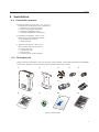
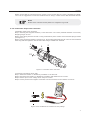
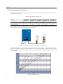
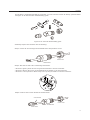
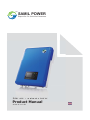
TM
SAMIL POWER
Expert for PV Grid-tied Inverters
SolarRiver-D
SolarR
River-D
DP
PV
VG
Grid-tied
riid-ttied
d IInverter
nvertter
Product Manual
SP-SR-D-V1.1-EN
English
Copyright Declaration
The copyright of this manual belongs to Samil Power Co., Ltd. Any corporation or individual should not plagiarize,
partially copy or fully copy it (including software, etc.), and should not reproduce or distribute it in any form or
by any means. All rights reserved. Samil Power reserves the right of final interpretation. This manual changes
according to user’s or customer’s feedback. Please check our website at www.samilpower.com for latest version.
01
02
CONTENTS
1 Notes On This Manual ......................................................................................................... 5
1.1 Scope Of Validity ...................................................................................................................
1.2 Target Group .....................................................................................................................
1.3 Important safety information .................................................................................................
1.4 Symbols Used ......................................................................................................................
1.5 Symbols on the Inverter ........................................................................................................
1.6 Important Safety Instructions .................................................................................................
5
5
5
5
5
6
2 Grid-tied System brief introduction .................................................................................... 7
3 Introduction of SolarRiver-D series inverter ....................................................................... 7
3.1 New features ........................................................................................................................ 7
3.2 Electrical block diagram .......................................................................................................... 8
3.3 Principle description .............................................................................................................. 8
3.4 Protection function ................................................................................................................ 9
3.5 Terminals of inverter
3.6 Dimension
............................................................................................................ 9
........................................................................................................................... 9
3.7 Product label ....................................................................................................................... 10
4 Operation Mode ................................................................................................................ 10
5 Installation ........................................................................................................................ 11
5.1 Installation process ............................................................................................................. 11
5.2 Packaging list ..................................................................................................................... 11
5.3 Safety instruction ................................................................................................................ 12
5.4 Installation precaution ......................................................................................................... 12
5.5 Installation tools .................................................................................................................. 14
5.6 Installation steps ................................................................................................................. 14
5.7 Connections of the PV power system ....................................................................................... 16
5.7.1 Announcements .......................................................................................................... 16
5.7.2 PV array connection types ........................................................................................... 16
5.7.3 Connection steps of DC connector .................................................................................. 17
5.7.4 Assembly steps of AC connector .................................................................................... 18
5.7.5 Grounding .................................................................................................................. 20
5.7.6 Connection of communication ....................................................................................... 20
6 Run the inverter ................................................................................................................ 21
6.1 Safety inspection ................................................................................................................. 21
6.2 Start inverter ....................................................................................................................... 21
6.3 interface setting .................................................................................................................. 21
7 Operation ........................................................................................................................... 24
7.1 Control and Display Panel ..................................................................................................... 24
7.2 Interface setting .................................................................................................................. 25
7.2.1 Home interface ........................................................................................................... 25
7.2.2 Main menu .................................................................................................................. 25
7.2.3 Instantaneous data ...................................................................................................... 25
7.2.4 Historical data
........................................................................................................... 25
03
7.2.5 Event list .................................................................................................................. 25
7.2.6 Settings
................................................................................................................... 25
8 Communication and Monitoring
....................................................................................... 27
8.1 Communication Interface ..................................................................................................... 27
8.2 Communication mode .......................................................................................................... 27
8.2.1 Ethernet communication .............................................................................................. 27
8.2.2 RS485 Communication ................................................................................................. 31
8.2.3 WIFI communication ................................................................................................... . 32
8.2.4 GPRS communication
................................................................................................. 34
9 Troubleshooting and maintenance
................................................................................... 36
9.1 Troubleshooting ................................................................................................................. 36
9.2 Daily maintenance .............................................................................................................. 38
10 Decommissioning .............................................................................................................. 38
10.1 Decommissioning steps ...................................................................................................... 38
10.2 Package ............................................................................................................................ 38
10.3 Storage ............................................................................................................................ 38
10.4 Disposal ........................................................................................................................... 38
11 Technical Data ................................................................................................................... 39
11.1 Input (DC) ........................................................................................................................ 39
11.2 Output (AC) ....................................................................................................................... 39
11.3 Efficiency ......................................................................................................................... 39
11.4 General data ..................................................................................................................... 40
12 Guarantees
04
....................................................................................................................... 41
Notes on This Manual
1 Notes on This Manual
This manual is an integral part of the inverter. Please read the product manual carefully before
installation, operation or maintenance. Keep this product manual for future reference.
1.1
Scope of Validity
This product manual describes the assembly, installation, commissioning, maintenance of the following
Samil Power SolarRiver-D series inverters.
SolarRiver 3400TL-D
SolarRiver 5000TL-D
1.2
SolarRiver 4000TL-D
SolarRiver 5200TL-D
SolarRiver 4500TL-D
Target Group
This manual is read by qualified electricians. The tasks described in this manual must only be performed
by qualified electricians.
1.3
Important Safety Information
Before installation or operation, please read the manual, or contact the local distributor. Please visit
the company website: www.samilpower.com for more information.
1.4
Symbols Used
There are some symbols in this manual in order to ensure personal and property security. Please read
the following symbols carefully.
Danger!
Danger indicates a hazardous situation, if not avoided, will result in death or
serious injury.
Note!
Note provides tips that are valuable for the optimal operation of your product.
1.5
Symbols on the Inverter
There are some symbols on the inverter in order to ensure personal and property security. Please read
the following symbols carefully.
Symbol
5 min
Explanation
Danger to life due to high voltages in the inverter!
There is residual voltage in the inverter. The inverter requires 5 minutes to
discharge.
• Wait 5 minutes before you open the upper lid or the DC lid.
Be care of hot surface.
The inverter can become hot during operation. Avoid contact during operation
Danger of high voltages
Danger to life due to high voltages in the inverter!
05
Notes on This Manual
1.6
Important Safety Instructions
When using the product, please remember the below information to avoid the fire, lightning or other
personal injury:
Warning!
Ensure input DC voltage ≤ Max.DC voltage .Over voltage may cause
permanent damage to inverter or other losses, which will not be included in
warranty! This chapter contains important safety and operating instructions.
Read and keep this Operation Guide for future reference.
Warning!
Authorized service personnel must disconnect both AC and DC power from the
SolarRiver-D Series inverter before any maintenance or cleaning or working on
any circuits.
● Before using the SolarRiver-D Series inverter, read all instructions and cautionary markings on the
SolarRiver-D Series inverter, and all appropriate sections of this guide.
● Recommend the attachments sold by Samil Power, otherwise may result in a risk of fire, electric shock,
or injury to persons.
● To avoid a risk of fire and electric shock, make sure that existing wiring is in good condition and wire
is not undersized. Do not operate the SolarRiver-D Series inverter with damaged or substandard wire.
● Do not disassemble the SolarRiver-D Series inverter. It contains no user-serviceable parts. See
warranty for instructions on obtaining service. Attempting to service the SolarRiver-D series inverter
by yourself may result in a risk of electric shock or fire and will void your warranty.
● To reduce the risk of electric shock, authorized service personnel must disconnect both AC and DC
power from the SolarRiver-D series inverter before any maintenance or cleaning or working on any
circuits connected to the SolarRiver-D Series inverter.
● Keep away from flammable, explosive materials to avoid fire disaster.
● The installation place should be away from humid or corrosive substance.
● To avoid electric shock accident, please do not disassemble the inverter because there are high-voltage
capacitances installed inside the inverter.
● To reduce the chance of short-circuits, authorized service personnel must use insulated tools when
installing or working with this equipment.
06
Grid-tied System brief introduction & Introduction of SolarRiver-D series inverter
2 Grid-tied System brief introduction
The SolarRiver-D series inverter is a PV inverter which converts the DC current of a PV generator into
AC current and feeds it into the public grid.
PV modules
Inverter
Public grid
Figure 1 PV Grid-tied System
SolarRiver-D series inverter has the latest technology, and strictly observe well recognized safety
procedures. Even so, misoperation will cause property destruction and personal injury.
Inverter must be reliably connected to utility power grid when working. The inverter is not designed
for mobile application.
The inverter was not used in any other or additional purposes. The manufacturer/supplier does not
take any responsibility for that. Must strictly abide by these relevant specifications of the manual.
3
Introduction of SolarRiver-D series inverter
3.1
New featuresity
In order to meet users the needs better, the SolarRiver-D series inverter has following new features
compared to the SolarRiver series inverter:
● Dual MPPT can be connected in Multi-string input or independent input so the system is de s ig n e d
flexibly and each individual MPPT can improve the efficiency of the system.
● MPPT range is wide, so expanding the voltage range. This feature adapts to the current trend which
voltage of PV is reduced, and the system is designed flexibly.
● Built-in DC Switch is optional. It can be the first time to cut off the DC source when in emergency.
This feature improves equipment, personnel safety in operation.
● 3.5 inch TFT LCD display, so human-machine interface is more friendly and convenient! The user
can see the real-time power data, operating mode, a day total generating capacity and other relevant
information!
● Must input password when setting specific grid codes which can be selected in the field. This feature
avoids the misoperation, ensure that the grid is more reliable and safe.
● Designed without fan, cooled by cooling fin at the rear side. This feature reduces power consumption
and running noise of machine.
● RS485,WIFI and GPRS is optional and ethernet interface for networking is standard in the inverter.
Users can analyse and monitor the data by Internet, Android, iPhone intelligent mobile phone.
● Built-in mass storage, store more historical data.
07
Introduction of SolarRiver-D series inverter
3.2
Electrical block diagram
Electrical block diagram of SolarRiver-D series inverter is as figure2.
Inverter
DC SPD
PV modules
AC switch
DC switch
Leakage
protection
AC SPD
Public grid
DC SPD
PV modules
Figure 2 Electrical block diagram of SolarRiver-D series inverter
3.3
Principle description
Principle description of SolarRiver-D series inverter is as figure3.
DC Switch
(Optional)
MPPT1
(DC/DC)
DC BUS
N
+
-
Inverter
(DC/AC)
LC Filter
PV 1
Relay
GFCI
L
MPPT2
(DC/DC)
N
+
PV 2
-
PE
PV
Insulation
Detection
RS485/WiFi/GPRS
LCD
DSP B
DSP A
ARM
RCMU
Ethernet
Figure 3 Principle description figure
08
Introduction of SolarRiver-D series inverter
3.4
Protection function
【Grounding fault】
SolarRiver-D series inverter is designed as floating connection with PV( positive and negative terminals
are not connected to ground ). When there is grounding fault, the inverter will be shut down and display
grounding fault.
【More equipment protection】
SolarRiver-D series can run safely in any working condition because of the following protections:
Continuous monitoring power grid, to ensure that the voltage and frequency is in the standard range;
When the environment temperature is beyond the range, inverter will limit power automatically and
so on.
Terminals of inverter
Venting Element
M16x1.5
RS-485
DC1
RS-485
DC2
RS-485
DC Input
LAN
LAN
AC Output
M16x1.5
3.5
AC
Antenna
Relay
Antenna Relay
Figure 4 Terminals of PV inverter
Normal
Fault
ESC
OK
320.5mm
230mm
120mm
115mm
180mm
111mm
21mm
Dimension
520mm
3.6
SolarR iver
244mm
380mm
175mm
Figure 5 Dimension
09
Introduction of SolarRiver-D series inverter & Operation Mode
3.7
Product label
The product label provides basic information of the inverter, which is attached to the right side of the
inverter. Pay special attention to the type of inverter and other specifications.
TM
TM
TM
PV Grid-tied Inverter
www.samilpower.com
Model: SolarRiver 3400TL-D
TM
PV Grid-tied Inverter
www.samilpower.com
Model: SolarRiver 4000TL-D
Absolute maximum voltage(Vmax)
550V
Absolute maximum voltage(Vmax)
Nominal operating voltage
360V
Nominal operating voltage
Absolute maximum current(Isc) 10.5/10.5A
Absolute maximum current(Isc)
Nominal operating voltage
Nominal operating voltage
230V
TM
PV Grid-tied Inverter
www.samilpower.com
Model: SolarRiver 4500TL-D
PV Grid-tied Inverter
www.samilpower.com
Model: SolarRiver 5000TL-D
550V
Absolute maximum voltage(Vmax)
550V
Absolute maximum voltage(Vmax)
360V
Nominal operating voltage
360V
Nominal operating voltage
12/12A
230V
Absolute maximum current(Isc) 13.5/13.5A
Absolute maximum current(Isc)
Nominal operating voltage
Nominal operating voltage
230V
PV Grid-tied Inverter
www.samilpower.com
Model: SolarRiver 5200TL-D
550V
Absolute maximum voltage(Vmax)
360V
Nominal operating voltage
15/15A
230V
550V
360V
Absolute maximum current(Isc)
15/15A
Nominal operating voltage
230V
Maximum continuous current
16A
Maximum continuous current
16A
Maximum continuous current
22A
Maximum continuous current
23A
Maximum continuous current
Nominal operating frequency
50Hz
Nominal operating frequency
50Hz
Nominal operating frequency
50Hz
Nominal operating frequency
50Hz
Nominal operating frequency
50Hz
Maximum continuous power
3000W
Maximum continuous power
3680W
Maximum continuous power
4000W
Maximum continuous power
4600W
Maximum continuous power
4600W
Maximum power
3200W
Maximum power
3680W
Maximum power
4300W
Maximum power
4600W
Maximum power
5000W
Power factor
0.95 lagging ~ 0.95 leading
Ingress protection
IP65
Operating
temperature range
-20/+60°C
Power factor
outdoor
0.95 lagging ~ 0.95 leading
Ingress protection
IP65
Operating
temperature range
-20/+60°C
outdoor
Class Ⅰ
Protective class
Communication Type
Communication Type
Made in China
G83/1
S/N:
XXX1223001
IP65
Operating
temperature range
-20/+60°C
RS485
Communication Type
IP65
Operating
temperature range
-20/+60°C
RS485
0.95 lagging ~ 0.95 leading
Ingress protection
IP65
Operating
temperature range
-20/+60°C
outdoor
Communication Type
RS485
Communication Type
RS485
Made in China
RoHS
S/N:
Class Ⅰ
Protective class
Made in China
AS4777 RoHS
XXX1223001
Power factor
Class Ⅰ
Protective class
Made in China
RoHS
0.95 lagging ~ 0.95 leading
Ingress protection
outdoor
S/N:
XXX1223001
Power factor
Class Ⅰ
Protective class
Made in China
AS4777 RoHS
S/N:
0.95 lagging ~ 0.95 leading
Ingress protection
outdoor
Class Ⅰ
Protective class
RS485
Power factor
24A
AS4777 RoHS
S/N:
XXX1223001
XXX1223001
Figure 6 Product label
4
Operation Mode
【standby Mode】
The standby mode means that the inverter is ready but still not connect to the grid. In this mode, it
will continue to check whether PV array has enough power to feedback into grid. When the inverter
has enough power, it will change from standby mode to Checking mode.
【Checking Mode】
If inverter has passed dump load test and no error/fault occurs, it will start checking to deliver power.
【On-grid Mode】
In this mode, SolarRiver-D series inverter convert PV array’s DC into AC and feedback into grid.
It is normal that the inverter decreases the output power in the condition of
thermal protection, but if this occurs frequently, you need to check the aircooling fin and the fan, or put the inverter in the place where has better air
flow. If the fan is too dirty, please clean it, and if output power decreases
caused by electric, please ask for professional supports.
【Fault Mode】
If any fault/error occurs, inverter will stop delivering power until the fault/error is removed. Some
fault/error will auto recover, and some may need manual restart.
10
Installation
5
Installation
5.1
Installation process
● Ready to install(refer to 5.2、5.3、5.4、5.5)
Complete the preparation before installation:
√ Read the user manual carefully;
√ Check the products and parts;
√ Inspection installation tools;
√ Checkthe installation environment.
● Mechanical installation(refer to 5.6)
Work during mechanical installation:
√ Fix the panel of inverter;
√ Install inverter.
●
5.2
Electrical connection(refer to 5.7)
Work during electrical connection:
√ Connect DC side;
√ Connect AC side;
√ Ground joint;
√ Connect line of communication.
Packaging list
Please check the package list, find out all these in the package. The product on the list are for installation.
If find some damage or some missing, please contact Samil Power’s sales.
1
8
2
3
9
4
5
6
7
10
11
TM
Sam
il Po
wer
Expe
rt for
PV Grid
-tied
Inverters
Solar
ProRiver-D Gri
duct d-t
-tie
ied
SRd Inv
D-V
1.0Man
ert
EN
ual er
SP-
Engli
sh
Figure 7 packing table
11
Installation
Table 1 packing list
Type
Equipment
Accessories
Files
5.3
Project
No.
Description
QTY
1
PV Grid-tied Inverter
1 unit
2
Bracket
1 pc
3
Installation Kit
1set
4
RJ45 plug
5
cable gland
1 pc
6
AC connector
1 pc
7
DC connector assembly
2 sets
8
Packing list
1 pc
9
Quality certifcation
1 pc
10
Product manual
1 pc
11
Warranty card
1 pc
Remark
1 set
for inverters without RS-485
3 sets
for inverters with RS-485
Safety instruction
DC voltage can be as much as 550 V, three-phase AC voltage reaches up to 270
V. Ensure AC/DC side uncharged before installing and maintaining the inverter.
Must observe the following standard and specifications strictly when installing, operating and maintaining
SolarRiver-D series inverter.
① Get the permission from the local power department then combine inverter to the grid and operate
by the professional electrical engineer.
② All the electrical installation must comply with local electrical installation standard.
③ Don't touch the other parts except terminals When installing.
④ There is high electrical voltage when working. Must cut off inverter AC/DC power and external control
power and wait for at least 5 minutes before maintaining
⑤ Pay attention to surface heat of inverter. For example, the power Semiconductor Devices still keep
higher temperature after blackout a period of time.
Pay attention to the rated voltage and current when design the system.
Please assess the following factors when designing PV system:
The largest input voltage of MPPT circuit in any case;
The largest input current of MPPT circuit in any case.
5.4
Installation precaution
Checking environment where system is installed:
SamilPower suggests customer check the installation site. Do not fall into any of the following conditions:
12
Installation
●
●
●
●
●
●
●
●
●
●
The ambient temperature is out the range of -20°C to +60°C
The altitude 2,000 m above sea level.
Prone to be damaged by water.
Close to corrosive gas or liquid (for example, locations where chemicals are processed or the location
where feed lots of poultry).
Exposed to direct sunlight.
Prone to be flooded or covered by snow.
Little or no air flow.
Exposed to steam, vapor, or water.
Exposed to direct cool air.
Near the television antenna or antenna cable.
The inverter is needed at least 30 cm (see figure 8) clearance. If not observe this there will be malfunction
of the system caused by water or high temperature inside the inverter.
30cm
Fault because of the above case is not in the scope of warranty.
30cm
30cm
Normal
Fault
ESC
OK
30cm
SolarRiver
Figure 8 Space specification
Choose inverter installation position:
●
●
●
●
Inverter must be installed on a solid surface which bears the weight of the inverter;
Tilted degree should not exceed 15 degree, as figure 9:
Terminals of inverter must be face down;
Can not be installed horizontally.
max 15
Figure 9 incorrect installation
13
Installation
5.5
Installation tools
Below tools are needed before installation.
5.6
Installation steps
Step1: Drill holes in the wall with diameter 6mm driller according to the size of bracket. Keep drilling
perpendicular to the wall, and don’t shake when drilling to avoid damage to the wall. Then put expansion
pipe into the hole, use rubber hammer to tap the pipe into the wall completely. Put the bracket into
expansion pipes and then use expansion screws to fasten bracket.
Mounting bracket on the wooden wall is as the following picture.
14
Installation
Step2:Put the inverter onto the bracket.
Step 3: Use M5 hex key nut to fix the bottom of the inverter.
Step4: Lock the inverter and the bracket with lock for safety. (This is optional for users. User can select
the lock according to your requirements).
15
Installation
5.7
Connections of the PV power system
5.7.1 Announcements
Ensure that the DC side is not charged before installation and maintenance.
But after DC side discharge for a period of time, the capacitor is still charged,
so need to wait for 5 minutes to ensure that the capacitors is discharged.
Before the electrical connection, make sure to use opaque material to cover
the PV battery or disconnected the breaker of DC side. Exposure to the sun, PV
array will produce a dangerous voltage.
5.7.2 PV array connection types
PV array connection types: There are 2 independent MPP trackers in inverter. You can choose common
-string input connection and multi-strings input connection. We recommend that choose multi-strings
to harvest max. PV power.
Figure 10 Multi-string input connection (Left) and common-string input connection (Right)]
Please select excellent function and reliable quality PV arrays. Open-circuit voltage of PV arrays should
be<Max. input DC input voltage. Operating voltage should be conformed to MPPT voltage range.
Table 2 DC Voltage Limitation
Model
MPPT voltage range
Max. DC voltage
16
SolarRiver
3400TL-D
SolarRiver
4000TL-D
SolarRiver
4500TL-D
SolarRiver
5000TL-D
SolarRiver
5200TL-D
160~500V
160~500V
165~500V
175~500V
175~500V
550 Vdc
Installation
Please use PV cable to connect arrays to inverter. From junction box to inverter, voltage drop is about
1-2%. So we suggest the inverter be installed near PV arrays, in order to save cable and reduce DC loss.
Note!
Please don’t connect the PV positive or negative to ground.
5.7.3 Connection steps of DC connector
● Assembly steps of DC connector
Step1: Inserting the stripped conductor, Cross-sections 2.5 to 6 mm2, Outside diameter 5.0 to 8 mm,
Stripping length 15 mm.
Step2: Close spring with the thumb or using combination pliers. Please ensure that the spring is closed.
(see figure 11)
Step3: Push connectors together (see figure11). Screw cable gland tight. Screw in the nut until it reaches
the O-ring and then tighten it with at least 2 Nm using a suitable tool. Finished.
1
4
2
15
3
Figure 11 Connection of the connector
● Electrical connections of DC side
Step1: Install the breaker or SolarArray Combiner in the DC side.
Step2: Disconnect the breaker or SolarArray Combiner with SolarRiver-D inverter.
Step3: Ensure open-circuit voltage of PV arrays is<1000V.
Step4: Put the positive and negative connector into the terminals on the bottom of inverter.
Figure 12 Use multimeter to measure PV array voltage
17
Installation
5.7.4 Assembly steps of AC connector
SolarRiver series inverters are designed for single phase grid. Technical data should comply with the
rule of local public grid.
Table 3 Cable and Micro-breaker rule
SolarRiver
3400TL-D
Model
Cable (Cu)
4mm²
Micro-Breaker
SolarRiver
4000TL-D
SolarRiver
4500TL-D
SolarRiver
5000TL-D
4mm²
4mm²
6mm²
20A
25A
32A
20A
SolarRiver
5200TL-D
6mm²
32A
Micro-breaker should be installed between inverter and grid, and the residual current is 30 mA≤Ifn≤300 mA.
Any load should not be connected with inverter directly.
ESC
Input
OK
Output
Figure 13 Incorrect Connections between Load and Inverter
Impedance of SolarRiver-D inverter AC connector should be less than 2Ω. To ensure anti-islanding
function reliable, wire loss power of PV cable should <1% of normal power. Length between inverter
AC side and grid connecting dot should be less than 150m. Relationship between cable and cable loss
is as following:
Figure 14 AC Cable Loss
18
Installation
This product is equipped with IP66 AC connector. You can connect inverter AC side by yourself. Please
see figure 15 for AC connector disassembling guide.
Figure 15 AC connector disassembling guide
Assembly steps of AC connector are as following:
Step1: Put the AC wire through the threaded sleeve and pressure screw.
Pressure screw
Threaded sleeve
Step2: Wire the AC side refer to following instructions.
• Screw the green-yellow wire to the ground terminator in the AC Connector
• Screw the N wire (blue wire) to the N(Neutral) terminator in the AC Connector.
• Screw the L wire (brown or black wire) to the L(Line) terminator in the AC Connector.
N
L
Step3: Confirm all the wires should be screwed down.
Connected wires
Pressure screw
Threaded sleeve
Socket element
19
Installation
Step4: Screw down the threaded sleeve.
Pressure screw
Socket element with threaded sleeve
Step5: Screw down the pressure screw.
Threaded sleeve
Pressure screw
Step6: Connect AC connector to inverter.
5.7.5 Grounding
Neither positive nor negative could grounding because of no transformer, or it
wil break down.
In the system, all non-current-carrying metal parts (such as shell of combiner, distribution and inverter)
should be connected to the earth.
PV String
AC Switchboard
Inverter
L
N
PE
PV module frame
Figure 16 grounding of system
5.7.6 Connection of communication
Please refer to part 8.2.2
20
EARTH
LINK
Run the inverter
6 Run the inverter
6.1
Safety inspection
PV array
Inspect the PV array to determine whether each PV array opening voltage meets the standard before
operating the inverter.
-Open-circuit voltage of PV arrays should be<Max. input DC input voltage;
-Ensure positive and negative polarity correct.
Collection of inverter DC side
Confirm DC side no voltages and currents by multimeter.
Check the wiring of DC side whether the wiring of polarity is consistent with PV array. Measure each
DC input voltage (open). Ensure that polarity is correct. Check voltage bias (in stable weather), if the
bias is more than 3%, PV array may has the problem.
Collection of inverter AC side
Ensure that the breaker of inverter AC side is “OFF”. Measure THD (total harmonic distortion) possibly,
then check the curve. If it is distorted seriously, the inverter can not run.
6.2
Start inverter
Steps of Start inverter are as following:
Step 1: Turn on DC switch.
Step 2: If it’s the first starting the inverter, please set accords to part 6.3.
Step 3: Turn on AC breaker.
If the inverter shows other fault, please refer to part 9--error table.
If the inverter fail, please refer to part 9 --error table.
6.3
interface setting
Enter start-up interface after starting inverter, shown as figure17.
SAMIL POWER CO., LTD.
Inverter type:
SolarRiver 5200TL-D
S/N:
S521233001
Master DSP SW:
V1.00
Slave DSP SW:
V1.00
HMI MCU SW:
V2.23
Press OK to start commissioning
Figure 17 start-up interface
Press "OK", will enter language setting interface automatically.
21
Run the inverter
Step1: language setting
Move the cursor to select language, press "OK" to select and press "OK" to confirm.
Language
English
German
French
Espana
Italy
Press OK to confirm
Note: Language setting is independent to Grid-tied country setting.
Step2: Grid-tied country setting
Next interface is grid-tied country setting interface. Different countries have different grid safety rules.
Move the cursor to select country, and then press “OK”to confirm. Then, press “OK” key to enter the
next step.
Country
Germany
Czech
Italy
GreeceIslands
Australia
GreeceContin
Spanish
Netherland
Press OK to confirm
Step3:Date and time settings
Set according to the local date and time. Press left or right arrow key to move the cursor, press the
up or down arrow keys to change value, then press “OK” to confirm. LCD will display time in the upper
right corner. Then, press “OK” key to enter the next step.
Note: Inverter will check whether the setting is legitimate when changing the time automatically, and
prevent illegal time value. If unable to modify time, please check whether it is legitimate.
22
Run the inverter
Date/Time
YYYY
2
0
MM
1
-
2
0
hh
1
0
:
3
DD
-
0
3
mm
1 0
Left/Right : Move Selection
Up/Down : Increase/Decrease value
Press OK to confirm
Step4:Check settings information
LCD will display the settings information. Please check the settings information. If setting is wrong,
please press the “ESC” to reset. If all the information is correct, please press “OK” to confirm, the
inverter will save all the settings.
End commission
Current Country:
Germany
Press OK to Start running
Press ESC to Back
Press OK to confirm
23
Operation
7 Operation
7.1 Control and Display Panel
Control and Display Panel of SolarRiver inverter is shown as figure 18.
Green LED
Red LED
2012-03-03 10 : 00 : 00
Home
Power
kwh
0.0 W
Today
Total
t
LCD
208.4 V
205.9 V
0.0 KWh
0.0 KWh
1.045 kw
=
~
Buttons
49.99 Hz
Press Esc to Main Menu
ESC
OK
S o larRiver
Figure 18 HMI Interface
There are 6 buttons: OK, ESC, UP, DOWN, RIGHT, LEFT.
OK button: confirm the selection.
ESC button: exit current screen or selection
Up button: move cursor to up selection or increase the values
DOWN button: move cursor to down or decrease the values.
RIGHT button: move cursor to right side or increase the backlight.
LEFT button: move cursor to left side or decrease the backlight.
There are two LEDS on the panel. Different LED status means inverter different working statutes.
Table 4 LED statutes
LED
flash
green
Wait state
red
Fault state
Wait: Inverter is checking in this state. If finds fault or error, will enter Fault or Permanent state.
normal:Inverter feeds AC current into grid. If any error or fault occurs, inverter will go to Fault State
or Permanent State.
fault:Inverter has checked some recoverable error. It can recover if the error disappears. If in Fault
State continually, you should check the inverter according to table 5.
permanent:Inverter has checked some unrecoverable error. You should take some measure or ask
for help.
When the inverter operates normally, user touch any button, then the backlight will be on, and inverter
will display home interface. If none key touched for 60 seconds, the backlight will be off. In next 10
seconds if still no operation the screen will back to home interface, otherwise the backlight will be
illuminated.
Note: After starting inverter and restoring the factory settings, LCD backlight will not shut down
automatically.
24
Operation
7.2 Interface setting
7.2.1 home interface
Enter home interface automatically after startup (If not the home interface, press “ESC” return to the
home interface), as shown in figure19.
2012-03-03 10 : 00 : 00
Home
Power
kwh
Today
Total
t
208.4 V
205.9 V
0.0 W
0.0 KWh
0.0 KWh
1.045 kw
=
~
49.99 Hz
Press Esc to Main Menu
Figure 19 home interface
7.2.2 main menu
In the home interface press “ESC” then enter the main menu, as shown in figure 20.
2012-03-03 10 : 01 : 00
Main Menu
Instantaneous values
History
Event List
Settings
System Info
Press Esc to Home
Figure 20 main menu
7.2.3 Instantaneous data
Move the cursor to the" Instantaneous" and then press “OK”, the user will see the input, output voltage,
current, power, temperature and other real-time information.
7.2.4 Historical data
Move the cursor to the" History" and then press “OK”, the user will see the power amount histogram
of every hour. The user press the left or right arrow key to see daily electricenergy production histogram
in the current month, mensal electricenergy production histogram in the current in the current year.
25
Operation
7.2.5 Event list
Move the cursor to the" Event List" and then press “OK”, the user will see the list of events of inverter.
Record 100 event information at most. Press the right or left keys to select events.
7.2.6 Settings
Move the cursor to the" Settings" and then press “OK”, the user will enter the setting interface, as
shown in figure 21.
Settings
2012-03-03 10 : 02 : 25
Language
Input config
Date/Time
Reset Password
Clear date
Network
Clear events
AutoTest(Italy)
LCD contrast
Factory set
Country
Safety param
Press Esc to Main Menu
Figure 21 settings interface
Some settings need to input password. There are 3 kinds of password: user password, installation
password and factory password. You can enter "Clear data", "Clear events", "Network" and "Reset
password" interface after inputting password.
1. Initial user password: 111111.
2. Password is composed of 6 figures.
3. If forget password, please contact installation contractor.
26
Communication and Monitoring
8 Communication and Monitoring
8.1
Communication Interface
Standard configuration:
1. Ethernet: Transmit the inverter working state such as output voltage, current, frequency, fault
information to the PC machine or other monitoring system. Ethernet can achieve multi-inverter wired
network at the same time.
Optional configuration:
WIFI: Wireless connect to route. Transmit the inverter working state such as output voltage, current,
frequency, fault information to the PC machine or other monitoring system. WIFI can achieve
multi-inverter wireless network at the same time.
RS485: Achieve multi-inverter network to monitor the inverter working state such as output voltage,
current, frequency, fault information
GPRS: Inform message by message.
Only choose one optional configuration when inverter is working.
8.2
Communication mode
When user want to know the information of the power system and monitor power system. We offer
following communications.
8.2.1 Ethernet communication
You can connect inverter to Internet by router (the router is not special for inverters, you can get any
brand in the market). Then you can see the inverter’s data in any place of the world.
WAN
Router
Figure 22 Ethernet communication
Hardware Requirements: computer which support windows(including xp,vista,win7), router, netting
twine, inverter(LAN mode).
Monitor mode: LAN and WAN.
LAN: Install SolarPower Browser in PC which can monitor inverters .In this mode, you can use a router
or nonuse.
If you use a router, you can monitor 254 inverters.
27
Communication and Monitoring
Parameter setting when using router:
Step 1:Enter home interface automatically after startup (If not the home interface, press “ESC” return
to the home interface).
2012-03-03 10 : 00 : 00
Home
Power
kwh
0.0 W
Today
Total
t
208.4 V
205.9 V
0.0 KWh
0.0 KWh
1.045 kw
=
~
49.99 Hz
Press Esc to Main Menu
Step 2: Press “ESC” in home interface then enter the main menu.
2012-03-03 10 : 01 : 00
Main Menu
Instantaneous values
History
Event List
Settings
System Info
Press Esc to Home
Step 3: Move the cursor to "settings" and then press “OK”, will enter settings interface.
Settings
2012-03-03 10 : 02 : 25
Language
Input config
Date/Time
Reset Password
Clear date
Network
Clear events
AutoTest(Italy)
LCD contrast
Factory set
Country
Safety param
Press Esc to Main Menu
28
Communication and Monitoring
Step 4: Move the cursor to "network", press "OK" and then enter "Input Password" interface.
2012-03-03 10 : 03 : 10
Input Password
Please input customer password
0
Left/Right : Move Selection
Up/Down : Increase/Decrease value
Press Esc to Settings
Step 5: Press "right" or "left" key to move the cursor to select the figure which need to be modified.
Press "up" or "down" key to modify figure. If the password is correct will enter 'Ethernet" interface.
Ethernet
2012-03-03 10 : 16 : 23
Auto-IP/DHCP
Manual-IP
Current mode: Auto-IP/DHCP
Press OK to confirm
Step 6: Move the cursor to "Auto-IP/DHCP", press "OK" twice. LCD interface will Reboot and then
enter into home interface automatically.
Ethernet
2012-03-03 10 : 16 : 40
Auto-IP/DHCP
Manual-IP
Current mode: Auto-IP/DHCP
Confirm?
If you don’t use a router, you can only monitor 1 inverter. Need to use cable to connect inverter with PC.
Parameter setting when not using router:
Refer to settings when using router:Main Menu->Settings->Network->Ethernet. In "Ethernet" interface
move the cursor to "Manual-IP", press "OK" twice(one press to confirm).
29
Communication and Monitoring
Ethernet
2012-03-03 10 : 22 : 23
Auto-IP/DHCP
Manud-IP
Current mode: Manual-IP
Press OK to confirm
Ethernet
2012-03-03 10 : 22 : 50
Auto-IP/DHCP
Manud-IP
Current mode: Manual-IP
Confirm?
Press "OK" twice then will enter "Manual-IP" interface. Press "right" or "left" key to move the cursor
to select the figure which need to be modified. Press "up" or "down" key to modify figure(IP Address:
192.168.000.002. Subnet Mask:255.255.255.000, others are 0). Press “OK” after modifying. LCD will
display the setting parameter and press “OK” again, now setting is over. LCD interface will Reboot and
then enter to home interface automatically.
Manual-IP
2012-03-03 10 : 26 : 05
IP:
192.168.000.002
SubnetMask:
255.255.255.000
Gateway:
000.000.000.000
DNS:
000.000.000.000
Left/Right : Move Selection
Up/Down : Increase/Decrease value
Press OK to confirm
Parameter set for PC:
Set IP address as 192.168.000.001,
Set Subnet mask as 255.255.255.000.
① Need to install SolarRiver-D inverter monitoring software in the PC when using
WIFI, Ethernet communication.
② Can’t using RS485 and Ethernet communication mode for a PC at the same time.
③ The default set is “Auto IP”. If use router, LAN or WAN monitor is available without
any parameter setting.
④ In WAN mode, must use router and recommend to select auto IP mode.
30
Communication and Monitoring
8.2.2 RS485 Communication
RS485 is generally for at most 32 inverters communication at the same time. But the length of
communication wire should be≤1200m. You can read and analyse data by PC if the system is equipped
with Solar-Log200/500/1000. Please refer to Solar-Log200/500/1000 manual for more information.
Figure 23 RS-485 jack
Two types of cable must be prepared before using Solar-Log to monitor mult-inverters.
The communication cable between inverter and inverter:
1. Prepare two 8-PIN RJ45 modular plug, hold the RJ45 modular plug with the 'clip' on the bottom,
the 'opening' (where you insert the cable) facing you, the order number is 1 to 8 from left to right,
as figure 24.
T-568B
Pin 1
1 2 3 4 5 6 7 8
RJ-45 Plug
O/ O G/ B B/ G Br/ Br
Figure 24
2. Use a length of communication cable, then push the 8 color wires into the modular plug follow the
same order as below.
1
orange white
2
orange
3
green white
4
blue
5
blue white
6
green
7
brown white
8
brown
3. Then put the both ends of communication cable into the communication ports of inverter respectively.
If there are N inverters, need N-1 this communication cable.
31
Communication and Monitoring
The communication cable between inverter and Solar-Log:
1. One side of cable is the same as cable between inverter and inverter, the other side remains 4 colour
wires: green white, green, orange white, orange, as shown in figure 25.
Figure 25
2.
Connect 4 colour wires to 1,4,5,6 port of Solar-Log.
1
green white
2
reserve
3
reserve
4
green
5
orange white
6
orange
8.2.3 WIFI communication
You can connect inverter to Internet by router. Then you can see the inverter’s data in any place where
internet is available.
WAN
Router
Figure 26 WIFI communication
OS: win xp, Vista, Win7;
Network: Lan or Wan;
Wifi: 802.11g.
32
Communication and Monitoring
WIFI settings:
Note:Appendix is WIFI route list.
Step1: Connect a cable following the steps of Ethernet before opening "SolarPower Browser".
Step2: Double-click name of inverter to enter detail information page. Set the SSID of router which
WIFI is going to be connected to and input the password(known from installation contractor) then save
these information.
Step3:Reboot the computer automatically and disconnect netting twine connection.
Step4:Check WIFI information:
Enter the interface successively: Main Menu->Settings->Network, move the cursor to "WIFI" and press
"OK".
2012-03-03 10 : 27 : 23
Network
Ethernet
WIFI
Press OK to confirm
33
Communication and Monitoring
The GUI bellow tells the WIFI hasn’t been set yet.
2012-03-03 10 : 28 : 10
Wifi
Link Name:
Press ESC to Back
If WIFI has been set, shown as following figure.
2012-03-03 10 : 28 : 50
Wifi
Link Name:
BAFFAL0-5D8959
Press ESC to Back
Hardware Requirements: router、inverter equipped with WIFI、PC(with
SolarPower Browser software)
8.2.4 GPRS communication
GPRS function is that sends fault message to user when inverter is at fault.
Hardware Requirements: SIM card, inverter equipped with GPRS, mobile telephone.
Monitor mode: message.
GPRS settings:
Step1: Use mobile telephone to set PIN code of SIM card which will be installed in inverter.
Step2: Connect cable following the steps of Ethernet before opening "SolarPower Browser".
34
Communication and Monitoring
Step3: Double-click name of inverter then enter detail information interface. Set the PIN code, service
center number and customer mobile telephone number then save these information.
Step4: Reboot the computer automatically.
Step5: Check GPRS information:
Enter the interface successively: Main Menu->Settings->Network, move the cursor to "GPRS" and
press "OK".
2012-03-03 10 : 27 : 23
Network
Ethernet
GPRS
Press OK to confirm
If GPRS setting has not been initialised, shown as following figure.
2012-03-03 10 : 29 : 10
GPRS Message
No settings
Press ESC to Back
35
Communication and Monitoring & Troubleshooting and maintenance
If GPRS setting has been initialised, press "OK" to check the information, shown as following figure.
GPRS Message
2012-03-03 10 : 32 : 06
PIN
1234
Center Number:
+8613800510500
Customer Number:
+8615000000000
Press OK to have a test!
Press ESC to Back
9
Troubleshooting and maintenance
9.1 Troubleshooting
This section illustrates possible faults of an inverter and solving methods and provides users with
troubleshooting tips to help them identify and solve common problems. Please read the following
troubleshooting steps:
1. Check the warning, fault messages or fault codes displayed on LCD. If a message is displayed, record
it before doing anything further.
2. Attempt the solution according to table 5.
3. If no fault message is displayed on LCD, check the following list whether the installation meet the
requirements.
—
—
—
—
—
Is the inverter installed in a clean, dry, adequately ventilated place?
Have the DC input switch been opened?
Do section area and length of cable meet requirements?
Are the input and output connections and wiring in good condition?
Are the configuration settings correct for user particular installation?
Steps of checking the warning and fault information displayed on LCD:
Move the cursor to the "Event list" and then press “OK” in main menu interface, then enter "Event list"
interface.
Events list
Code
40
10
09
08
08
2012-03-03 10 : 42 : 07
Message
Bus over voltage
2012-03-03 10 : 40 : 36
PV2 over voltage
2012-03-03 10 : 40 : 34
PV1 over voltage
2012-03-03 10 : 40 : 34
No utility
2012-03-03 10 : 40 : 22
No utility
2012-03-03 10 : 40 : 14
01/20
Press ESC to Main Menu
Figure 27 Event list interface
36
Troubleshooting and maintenance
When SolarRiver-D inverter is at fault, the fault information is composed of code, occurring time and
fault description.
Please contact Samil Power Co.,Ltd for further technical assistance. Please provide detailed installation
information and inverter model, serial number and fault information.
Table 5 Troubleshooting list
Faults
Grid volt / freq over /
underrating
Diagnosis and Solutions
-Wait grid go back to normal working state.
-Mak sure that grid voltage and frequency complies with standards.
-Or, please ask for help
No Utility
-Check grid-connection
-Or, please ask for help.
PV1/PV2 over voltage
-Check the PV open-circuit voltage whether it is >Max.DC voltage.
-Or, please ask for help.
DCI out range
- Wait for one minute.
-Or, please ask for help.
SCI/ SPI communication
fault
-Disconnect DC and AC side, and connect them again.
-Or, please ask for help.
PV1/PV2 isolation fault
-Check the impedance among PV (+)、PV (-) and grounding whether
they are>600Kohm.
-Or, please ask for help.
Consistent Fault
-Disconnect DC and AC side, and connect them again.
-Or, please ask for help.
Relay Failure
-Disconnect DC and AC side, and connect them again.
-Or, please ask for help.
GFCI over 30mA /60mA /
150mA /300mA fault
-Check whether leakage current is too high.
-Disconnect DC and AC side, check the surrounding equipment on the
AC side.
-Reconnect the input side and check inverter after troubleshooting.
-Or, please ask for help.
EEPROM read/ write failure
-Disconnect DC and AC side, and connect them again.
-Or, please ask for help.
Bus over voltage
-Disconnect DC side, and connect them again.
-Check L line and N line whether it has connection faults.
-Or, please ask for help.
GFCI device failure
-Disconnect DC and AC side, and connect them again.
-Or, please ask for help.
Input/ output current high
-Disconnect DC and AC side, and connect them again.
-Or, please ask for help.
37
Troubleshooting and maintenance & Decommissioning
9.2
Daily maintenance
Inverters generally do not need any maintenance or calibration, but ensure air-cooling fin not be covered
by any dust or dirties.
Inverter cleaning
Please use electric drier, soft dry cloth or brush to clean inverters. Water, corrosive chemical substance
or intense cleaning agent are not allowed to clean the inverter.
Cooling fin cleaning
To ensure inverter good performance and long-period usage, cooling fin needs to be left with adequate
space. Please use electric drier, soft cloth or brush to clean cooling fin. Water, corrosive chemical
substance or intense cleaning agent is not allowed.
10 Decommissioning
10.1 Decommissioning steps
1. Switch off the AC grid;
2. Switch Off the DC switch;
3. Wait 5 minutes;
4. Release the DC connectors;
5. Release the AC connectors.
Now inverters can be demounted safely.
10.2 Package
Please pack the inverter with the original package as far as possible. If original package is not available,
use an equivalent carton that meets the following requirements:
1. Load more than 50 kg;
2. With handle;
3. Can be fully sealed off.
10.3 Storage
Store the inverter in dry place where temperatures are between -25 °C - +70 °C.
10.4 Disposal
Please deliver inverters and packing materials to a suitable space where should meet disposal regulations
for electronic scrap at the end of its service.
38
Technical Data & Guarantees
11.4 General data
Model
SolarRiver
3400TL-D
Dimensions(W/H/D) [mm]
Weight [kg]
Operating temperature
range [°C]
Ingress protection
Topology
Internal consumption
(night) [W ]
Cooling concept
Noise (typical) [dB]
LCD display
Communication
Standard warranty [year]
SolarRiver
4000TL-D
SolarRiver
4500TL-D
SolarRiver
5000TL-D
SolarRiver
5200TL-D
520 / 380/ 175
23
25
-20~+60
IP65
Tansformerless
<3
Convection
<30
3.5 inch TFT LCD
Ethernet / optional for RS485/GPRS/WiFi
5
12 Guarantees
Samil Power Co., Ltd offers 5 years warranty service for SolarRiver-D inverter. Warranty period is from
the date of installation. But the longest period don’t exceed 66 months from the date of delivering goods.
During the warranty period, Samil Power Co., Ltd guarantees normal function of the SolarRiver-D
inverter. If there are faults within our responsibility, we will provide maintenance free of charge.
During the warranty period, if inverter appears malfunction or fault, please contact your dealer or
installation contractor.
40
The followings are not included in the scope of warranty:
√ Use SolarRiver-D inverter for other purpose;
√ Install incorrectly or not conform to the rule;
√ Improper operation
√ Useunqualified protection when working;
√ Modify the equipment without authority;
√ Damage because of external factors or the majeure force(such as lightning, over-voltage, bad weather,
and fire, earthquake, tsunami and so on);
√ Poor ventilation;
√ Don’t comply with the relevant safety regulations;
√ Transportation damage.