1
ILS-606DBR
ILS-606DSR
ILS-625DCR
USER MANUAL
This manual includes instructions and overview on the following 3 CHAUVET products;
ILS-606DBR, ILS-606DSR and ILS-625DCR.
th
CHAUVET, 3000 N 29 Ct, Hollywood, FL 33020 U.S.A
(800) 762-1084 – (954) 929-1115
FAX (954) 929-5560
www.chauvetlighting.com
2005-01-11/17:17
TABLE OF CONTENT
TABLE OF CONTENT ............................................................................................................................................................... 2
BEFORE YOU BEGIN................................................................................................................................................................ 3
WHAT IS INCLUDED ............................................................................................................................................................................................. 3
UNPACKING INSTRUCTIONS .................................................................................................................................................................................. 3
AC POWER ........................................................................................................................................................................................................ 3
SAFETY INSTRUCTIONS ....................................................................................................................................................................................... 3
INTRODUCTION......................................................................................................................................................................... 4
FEATURES ......................................................................................................................................................................................................... 4
DMX CHANNEL SUMMARY ................................................................................................................................................................................... 4
WHAT IS ILS? .................................................................................................................................................................................................... 4
PRODUCT OVERVIEW .......................................................................................................................................................................................... 5
SETUP......................................................................................................................................................................................... 6
LAMP................................................................................................................................................................................................................. 6
Lamp installation .................................................................................................................................................................................... 6
POWER.............................................................................................................................................................................................................. 6
MOUNTING ......................................................................................................................................................................................................... 7
Hanging Bracket & Fixture Floor Stands.................................................................................................................................................. 7
Orientation ............................................................................................................................................................................................. 7
Rigging .................................................................................................................................................................................................. 7
LAMP ALIGNMENT ............................................................................................................................................................................................... 7
Lamp Alignment How-To ........................................................................................................................................................................ 7
OPERATING INSTRUCTIONS .................................................................................................................................................. 8
MENU NAVIGATION ............................................................................................................................................................................................. 8
OPERATING MODES ............................................................................................................................................................................................ 9
Stand Alone ........................................................................................................................................................................................... 9
Master/Slave .......................................................................................................................................................................................... 9
DMX Mode............................................................................................................................................................................................. 9
MENU FUNCTIONS .............................................................................................................................................................................................. 9
DMX-512 addressing {Addr}......................................................................................................................................................................... 9
Setting the starting address .................................................................................................................................................................. 10
Master/Slave settings {SLNd} {SL 1} {SL 2}........................................................................................................................................ 10
Setting the alternate slave mode {SL 2}................................................................................................................................................. 10
User Configurations {CLNd}, {IPan}, {ItLt}, {Irot}-606DBR, {IdIN} ................................................................................................................. 11
Color Mode {CLNd} .............................................................................................................................................................................. 11
Pan Invert {IPan} – tilt Invert {ItLt} – {Irot}............................................................................................................................................... 11
DIMMER INVERT {IdIN} – (Ver B. Models)............................................................................................................................................ 11
Segment Display Configurations {Led}, {IdSP}............................................................................................................................................ 11
Turning the Display off {Led}................................................................................................................................................................. 11
Display Inverse {IdSP} .......................................................................................................................................................................... 12
Fixture Test and Service Functions {FAdJ}, {teSt}, {FhrS}, {rSet}................................................................................................................. 12
Focus Adjustment {FAdJ}...................................................................................................................................................................... 12
Fixture Self-Test {teSt}.......................................................................................................................................................................... 12
Fixture Reset {rSet} .............................................................................................................................................................................. 12
Fixture Hours {FhrS}............................................................................................................................................................................. 12
CA-8 & CA-8F Easy Controller (Optional) ................................................................................................................................................... 13
APPENDIX ................................................................................................................................................................................ 14
DMX PRIMER ................................................................................................................................................................................................... 14
Fixture Linking...................................................................................................................................................................................... 14
DMX CHANNEL VALUES (606DSR & 606DBR).................................................................................................................................................... 15
DMX CHANNEL VALUES (625DCR) .................................................................................................................................................................... 16
GOBOS ............................................................................................................................................................................................................ 17
VERSION (B) MODELS ....................................................................................................................................................................................... 17
MAINTENANCE.................................................................................................................................................................................................. 18
RETURNS PROCEDURE...................................................................................................................................................................................... 18
CLAIMS ............................................................................................................................................................................................................ 18
GENERAL TROUBLESHOOTING............................................................................................................................................................................ 19
TECHNICAL SPECIFICATIONS .............................................................................................................................................................................. 20
TECHNICAL SUPPORT ........................................................................................................................................................................................ 20
ILS-606 & ILS-625 User Manual
2
2005-01-11/17:17
BEFORE YOU BEGIN
What is included
One of the following;
ILS-606DBR - Trackscan 250DBR-ILS™
ILS-606DSR - Trackscan 250DSR-ILS™
ILS-625DCR - Colortrack 250DCR-ILS™
Power cord with plug
MSD-250 Discharge lamp
Removable Floor Stands
Warranty Card
Unpacking Instructions
Immediately upon receiving a fixture, carefully unpack the carton, check the contents to ensure that all
parts are present, and have been received in good condition. Notify the shipper immediately and retain
packing material for inspection if any parts appear damaged from shipping or the carton itself shows signs
of mishandling. Save the carton and all packing materials. In the event that a fixture must be returned to
the factory, it is important that the fixture be returned in the original factory box and packing.
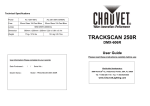
AC Power
To determine the power requirements for a particular fixture, see the label affixed to the back plate of the
fixture or refer to the fixture’s specifications chart. A fixture’s listed current rating is its average current draw
under normal conditions. All fixtures must be powered directly off a switched circuit and cannot be run off a
rheostat (variable resistor) or dimmer circuit, even if the rheostat or dimmer
Figure 1 - AC Voltage Switch
channel is used solely for a 0% to 100% switch. Before applying power to a
fixture, check that the source voltage matches the fixture’s requirement. Check the
fixture or device carefully to make sure that if a voltage selection switch exists that
it is set to the correct line voltage you will use.
Warning!
Verify that the power select switch on your unit matches the line voltage applied. All
fixtures must be connected to circuits with a suitable Earth Ground.
Safety Instructions
Please read these instructions carefully, which includes important
information about the installation, usage and maintenance?
Please keep this User Guide for future consultation. If you
sell the unit to another user, be sure that they also receive
this instruction booklet.
Always make sure that you are connecting to the proper
voltage and that the line voltage you are connecting to is
not higher than that stated on decal or rear panel of the
fixture.
This product is intended for indoor use only!
To prevent risk of fire or shock, do not expose fixture to
rain or moisture. Make sure there are no flammable
materials close to the unit while operating.
The unit must be installed in a location with adequate
ventilation, at least 50cm from adjacent surfaces. Be sure
that no ventilation slots are blocked.
Always disconnect from power source before servicing or
replacing lamp or fuse and be sure to replace with same
lamp source.
Secure fixture to fastening device using a safety chain.
Never carry the fixture solely by its head. Use its carrying
handles.
Maximum ambient temperature is Ta: 40°. Do not operate
fixture at temperatures higher than this.
In the event of serious operating problem, stop using the
unit immediately. Never try to repair the unit by yourself.
Repairs carried out by unskilled people can lead to
damage or malfunction. Please contact the nearest
authorized technical assistance center. Always use the
same type spare parts.
Don’t connect the device to a dimmer pack.
Make sure power cord is never crimped or damaged.
Never disconnect power cord by pulling or tugging on the
cord.
Avoid direct eye exposure to lamp while it is on.
Caution!
There are no user serviceable parts inside the unit. Do not open the housing or
attempt any repairs yourself. In the unlikely event your unit may require service,
please contact CHAUVET.
ILS-606 & ILS-625 User Manual
3
2005-01-11/17:17
INTRODUCTION
Features
7 interchangeable rotating gobos
9 trapezoid cut dichroic colors plus white
manual focus
mechanical dimming
super bright 250 watt discharge lamp, 2000 hour life
switch-selectable power settings 115V or 230V, (240V version available)
clear digital segment display
ILS Integrated Lighting System for advanced pre-programmed functions
high efficiency optical system
removable fixture floor stand
dichroic coated optics
DMX Channel Summary
606DBR & 606DSR
625DCR
CHANNEL
FUNCTION
CHANNEL
FUNCTION
1
Pan
1
Shutter
2
606DBR: Barrel rotation
606DSR: Tilt
2
Gobos
3
Shutter
3
Color
4
Gobos
4
Gobo Rotation
5
Color
5
Dimmer
6
Gobo Rotation
7
Dimmer
What is ILS?
ILS stands for Integrated Lighting System. CHAUVET fixtures with the ILS logo
are equipped with an advanced independent show technology that enables
synchronization across all intelligent lighting fixtures within the group.
Gobos, colors and chases are among the various features that
synchronize. In Master/Slave mode, the first fixture in the chain will
automatically address fixtures that follow. In conjunction with the ILSCON controller, ILS fixtures are also addressed remotely by the controller
further reducing the time to setup prior to a show.
In short, CHAUVET’s ILS fixtures give the user the power and the speed
to perform efficiently and effectively in the shortest possible time.
ILS-606 & ILS-625 User Manual
4
2005-01-11/17:17
Introduction
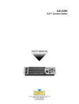
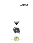
Product Overview
606DBR
606DSR
Carrying
handle
Multimirrored
Barrel
Scan Mirror
Pan/Tilt Arm
Adjustable
Lens Gun
Hanging
Bracket
Front cover
bolts
625DCR
Removable
Fixture Floor
Stands!
LED Segment Display
I/O Panel located on bottom
of fixtures
LED SEGMENT DISPLAY OVERVIEW
LED INDICATORS
STATUS
FUNCTION
DMX
On
DMX input is present
MASTER
On
Unit is in the Master operating mode
Slave
On
Unit is in the Slave operating mode
Sound
Flashing
Sound Active mode is on
Figure 2 Product Overview
SEGMENT BUTTONS I/O PANEL OVERVIEW
BUTTONS
I/O PANEL
MENU
Toggles programming
functions
DMX Out & In
DMX-512 connectors
DOWN
Steps backward through menu
functions
MIC
Built in microphone
UP
Steps forward through menu
functions
Sensitivity POT
Sets audio sensitivity
ENTER
Confirms selected menu
function
Remote control
Accepts ¼” connector from the “CA-8 or CA-8F
Easy Controller” providing Stand By, Strobe/Next
and Show1 1/Slow/Show 2 functions.
ILS-606 & ILS-625 User Manual
5
2005-01-11/17:17
SETUP
Lamp
You will need to install a lamp prior to the initial operation of the fixture. A MSD250 high intensity discharge
lamp is included.
Warning!
When replacing the lamp, please wait 15 minutes after powering down to allow the
unit to cool down! Always disconnect from main power prior to lamp replacement.
Do not touch the envelope (glass area) of the bulb with bare hands. If this happens, clean the lamp with
alcohol and wipe it with a lint free cloth before installation.
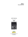
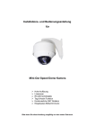
L AMP I NST AL L AT I O N
1)
ILS-6xx Lamp Installation
Remove both thumbscrews located on the bottom of the
fixture.
2)
Pull out lamp socket plate as pictured to the right.
3)
If replacing the lamp, remove old lamp first.
4)
Holding the new lamp by its base, align the small pin on the
lamp with the small hole in the socket and insert the lamp
squarely until the retaining clips on the lamp socket secures
the lamp tightly.
Lamp alignment screws
P O WE R
PI N1 - C O M M
PI N2 - D M X
PI N3 - D M X
+
O U T P UT
F U SE
5)
Clean the glass/envelope of the bulb with an alcohol wipe
or equivalent.
6)
Holding the lamp socket plate, insert the tip of the lamp into
the fixture with extreme care. Navigate the lamp all the way
until it reaches the reflector and the lamp base plate
touches the bottom plate of the fixture.
7)
Align the screw holes and fasten the thumbscrews back
onto the lamp socket plate.
8)
If you are replacing the lamp, you may want to log the
fixture hours in order to track the lamps use. Navigate to the
{FhrS} on the menu display to obtain this information.
9)
Turn the fixture on and adjust the lamp alignment screws
until the brightest most even area of the beam is in the
center of your spot. It may be necessary for you to use a
controller in order to command the fixture to display a white
beam on a flat surface with no gobos or colors.
IN P UT
A d ju s t la m p p o s it i o n b y tu r n i n g s c r e w s A , B a n d C .
D is c o n n e c t p o w e r a n d w a i t 5 m in . b e f o r e o p e n in g .
S
M od el :
S er ia l No :
P ow er :
F use :
B ul b :
Q
C
SE
D
MI C
CO NF I G UR AT I O N
CH 1= PA N
CH 2= T IL T RO TA T I ON
CH 3= S HU T TE R / S HA K I NG
CH 4= G OB O
CH 5= CO LO R
CH 6= G OB O R O TA T IO N
CH 7= DI M M E R
A
S EN SI T I VI T Y
P
O NL Y F O R
RE M O T E C O NT RO L
Remove both thumbscrews
Power
Your product is equipped with switch-selectable AC power setting.
Warning!
Verify that the power select switch on your unit
matches the line voltage applied. All fixtures must
be connected to circuits with a suitable Earth
Ground.
Slide switch up or down
depending on your line voltage.
To determine the power requirements for a particular fixture,
see the label affixed to the back plate of the fixture or refer to the fixture’s specifications chart.
A fixture’s listed current rating is its average current draw under normal conditions.
All fixtures must be powered directly off a switched circuit and cannot be run off a rheostat
(variable resistor) or dimmer circuit, even if the rheostat or dimmer channel is used solely for a 0%
to 100% switch.
Before applying power to a fixture, check that the source voltage matches the fixture’s
requirement.
All fixtures must be connected to circuits with a suitable Earth Ground.
ILS-606 & ILS-625 User Manual
6
2005-01-11/17:17
Setup
Mounting
H ANG I NG BRACKET & F IXT URE F LO O R STANDS
Mount the hanging bracket on the fixture as illustrated on the right. The
tension knob is unique in that it is self ratcheting, providing you tool-free
tensioning of the bracket. Pull knob handle towards you and turn either to
apply tension or to release tension. Also included are two fixture floor
stands and a convenient hex wrench tool for fastening them. The wrench
also opens the fixture’s front and back covers.
O RI ENT AT I O N
This fixture may be mounted in any position provided there is adequate room for ventilation. It is also
possible to stand this fixture using the removable floor stands.
Hanging Bracket
RI G G I NG
It is important never to obstruct the fan or vents pathway. Mount the fixture
using, a suitable “C” or “O” type clamp. Adjust the angle of the fixture by
loosening both knobs and tilting the fixture. After finding the desired
position, retighten both knobs.
When selecting installation location, take into consideration lamp
replacement access and routine maintenance.
Safety cables should always be used.
Never mount in places where the fixture will be exposed to rain,
high humidity, extreme temperature changes or restricted ventilation.
Note!
Clamp is sold separately.
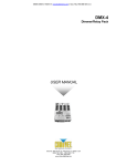
Lamp Alignment
L AMP AL I G NMENT HO W-T O
Often, after a new installation of a lamp, you will find that there is an uneven field of light or what is referred
to as a hot spot. This is due to the most intense point of the lamp source not being positioned optimally
within the reflector.
Lamp alignment screws
There are three lamp alignment screws provided
PO WER
at the base of the fixture. Turning these screws
allow you to optimize the projection quality of the
PIN 1 - CO MM
PIN 2 - DM X PIN 3 - DM X +
spot as well as the overall intensity of the beam.
OU TPU T
FU SE
IN P UT
Project a white spot against any flat
surface. Preferably the surface should be
white or pastel in color.
A djus t la m p p os itio n by tur nin g s c r e ws A ,B a nd C .
D is c onne c t pow e r a nd wa it 5 m in. be fo re ope ning .
Even out this plate by turning the
lamp alignment screws, prior to
lamp optimization. This will
provide you a good starting point.
ON LY FOR
R EM OTE C ON TR OL
S EN S ITIV ITY
M IC
CON F I GU RAT I ON
CH 1 =PA N
CH 2 =T I LT R OT AT I ON
CH 3 =S HU T T ER / SH AK IN G
CH 4 =G OBO
CH 5 =C OL OR
CH 6 =G OBO R OTAT I ON
CH 7 =D I MM ER
Mo d el:
Se rial N o:
Po w er:
F use :
Bu lb:
PA Q
S C
S
E
D
1)
2)
Turning the lamp alignment screws, try to
position the hot spot in the center of the
beam as best as possible. This could
require many attempts on your part. It is advisable to even out the screws prior to
lamp alignment as described in the illustration.
3)
Once the hot spot is in the center of the spot, do your best to turn all screws equally as
to affect movement up or down within the reflector.
4)
As you move in and out of optimum lamp focus, you will see the hot spot either get wider
or narrower. The goal is to either totally diminish the hot spot by having it widen and
spread across the entire spot or moving the hot spot so that it covers as much of the beam
spot area as possible.
ILS-606 & ILS-625 User Manual
7
2005-01-11/17:17
OPERATING INSTRUCTIONS
Menu Navigation
To select any of the pre-set functions, press the MENU button until the desired function is shown on the
display. Select the function by pressing the ENTER button and the display will blink. Use the DOWN and
UP button to change the settings. Once the required setting has been selected, press the ENTER button to
activate it. If you don not press the ENTER button, it will automatically return to the main functions without
any change after idling 8 seconds. To go back to the functions without any change press the MENU
button. The main functions are shown below:
MENU
Addr
DMX-512 Address Setting
1 ~ 512
SL 2
Slave mode “2 Light Show”
SLNd
SL I
Slave mode “Normal”
N bo
Blackout mode “No to blackout”
bLNd
Y bo
Blackout mode “Yes to Blackout”
SC
Split Color
CLNd
No
Normal Color
I
Pan Inverse
IPan
No
Pan Normal
I
606DSR - Tilt Normal
606DBR - Barrel Rotation Normal
ItLt (606DSR)
or
Irot (606DBR)
No
606DSR – Tilt Inverse
606DBR – Barrel Rotation Inverse
ON
Display On
LEd
OFF
Display Off
dSPI
Display Normal
IdSP
IdSP
Display Inverse
I
Dimmer Inverse
IdIN
No
Dimmer Normal
FAdJ
Focus adjust
test
Self test
FhrS
Fixture hours
rSeT
Reset
Figure 3 - Display Panel Diagram
Upon powering up the unit, you will notice that it will display a fixture ID. In addition, the fixtures electronics
will load up its programming and home (adjust) its motors to a starting position. The sequence of events
ILS-606 & ILS-625 User Manual
8
2005-01-11/17:17
Operating Instructions
should take no more than 20 seconds and it is necessary for the fixture to operate correctly. During this
time you will hear motor and mechanical movement inside the fixture. After this initial power-up sequence,
if the fixture receives no DMX signal, it will enter into a stand alone mode. Be sure to power up your DMX
controller device before the lighting fixture to avoid unwanted auto mode operation.
Operating Modes
All models can be operated in three different ways.
A stand-alone mode will listen to sound and run through its diverse range of built in programs.
Master/Slave mode will allow the command of up to as many units you want in a synchronized
light show to the sound.
DMX control mode will provide the greatest flexibility and creativity. Each fixture trait can be
controlled individually using any universal DMX-512 controller.
ST AND AL O NE
The Stand Alone mode is activated automatically when the fixture is absent of DMX signal or a controller is
not connected. All models will run through their built in programs as they listen to the sound.
MAST ER/ SL AVE
The Master/Slave mode will allow you to link multiple units in a daisy chain fashion. In this mode, the first
unit in the daisy chain will automatically command all other units following. The ILS system provides for the
synchronization of all CHAUVET products whose model number is pre-fixed by the letters ILS.
Master/Slave operation does not require any menu or setting selections. Simply connect each fixture in a
daisy like fashion using qualified 3 pin DMX cables as described below. The first unit in the chain will
operate in a Stand/Alone mode and all units following will synchronize to the first unit.
1)
Connect the (male) 3 pin connector side of the DMX cable to the output (female) 3 pin connector of
the first fixture.
2)
Connect the end of the cable coming from the first fixture which will have a (female) 3 pin connector
to the input connector of the next fixture consisting of a (male) 3 pin connector. Then, proceed to
connect from the output as stated above to the input of the following fixture and so on as illustrated
below in “Daisy Chain Connection”.
Daisy Chain Connection
Optional
DMX MO DE
Operating in a DMX Control mode environment gives the user the greatest flexibility when it comes to
customizing or creating a show. You can tailor your programming to suit a specific event. Whether it is a
wedding where a spot light may be required or a lead singer requiring a color solo, the opportunities are
endless. In this mode you will be able to control each individual trait of the fixture independently.
Menu Functions
DMX-512 addressing {Addr}
This mode enables the use of a universal DMX controller device. Each fixture requires a "start address"
from 1 to 511. A fixture requiring one or more channels for control begins to read the data on the channel
indicated by the start address. For example, a fixture that occupies or uses 6 channels of DMX and was
addressed to start on DMX channel 100, would read data from channels: 100, 101, 102, 103, 104, and
ILS-606 & ILS-625 User Manual
9
2005-01-11/17:17
Operating Instructions
105. Choose start addresses so that the channels used do not overlap and notate the start address
selected for future reference.
If this is your first time addressing a fixture using the DMX-512 control protocol than I suggest jumping to
the Appendix Section and read the heading “DMX Primer”. It contains very useful information that will help
you understand its use.
Caution!
FIXTURE
DMX CHANNELS
NOTES
ILS-606DSR
7
ILS-606DBR
7
ILS-625DCR
5
When calculating the next starting address for a particular fixture, simply add
the number of channels used by the last fixture to the starting address of the
last fixture. The result is the starting address of the next fixture.
Example:
Fixture # 1 Uses 7 Channels, Set to DMX 001
Add 7 to the previous start address
007 +
Fixture # 2 Uses 6 Channels, Set to DMX 008 Total
Add 6 to the previous start address
006 +
Fixture # 3 Uses 4 Channels, set to DMX 014 Total
Some controllers are factory configured to control a specific range of channels per
fixture. For example, you may have a controller pre-set to control 10 channels per
fixture for a total of 12 fixtures. In this case you would be required to separate all
fixtures in 10 channel increments instead of the true number of channels your
particular fixture utilizes.
SET T I NG T HE ST ART I NG ADDRESS
1)
Press the MENU button until the display reads {Addr}.
2)
Press the ENTER button to select DMX addressing. Once selected the display will read either a 1 or
any other number that may have previously been set. You must make a selection within 6 seconds.
3)
Press the UP and DOWN buttons to increase or decrease values until the desired value is achieved.
4)
Press the ENTER button to activate selection.
Master/Slave settings {SLNd} {SL 1} {SL 2}
By linking the units under a master/slave control mode, the first unit can direct additional units to create a
sound activated, synchronized light show. This is very useful for mobile DJs who want to setup and run a
show quickly.
In this mode the fixture is assigned a master status and is indicated by the MASTER LED. If the fixture is
not connected to a controller then it will automatically enter a sound activated state. You can adjust the
microphone sensitivity pot on the fixture for optimum sound recognition. Any other units connected will
automatically be assigned to {SL 1} mode, which is the standard Slave mode providing unison
synchronized movements and gobo-color changes.
SET T I NG T HE ALT ERNAT E SL AVE MO DE {SL 2}
Unlike {SL 1}, {SL 2} enhances the pre-programmed shows by contrasting the movements. Once you
select this mode, the fixture will remember it the next time your power up.
1) Tap the MENU button until the display reads {SLNd}.
2)
Press the ENTER button to select this function. The selection is confirmed when the display begins to
blink. You must make a selection within 8 seconds.
3)
Press the UP and DOWN buttons to toggle between the Slave Shows available. Note! There are 4
shows available in Model # ILS-625DCR and 2 shows in the rest.
4)
Press the ENTER button to activate selection.
ILS-606 & ILS-625 User Manual
10
2005-01-11/17:17
Operating Instructions
User Configurations {CLNd}, {IPan}, {ItLt}, {Irot}-606DBR, {IdIN}
All of the fixtures have three user selectable run-time configurations that change the behavior of a certain
function. The three functions are described below.
CO L O R MO DE {CL ND}
This mode allows you to select whether your controller will access the color palettes in solid colors only or
solid and split colors.
1)
Tap the MENU button until the display reads {CLNd}.
2)
Press the ENTER button to select this function. The selection is confirmed when the display begins to
blink. You must make a selection within 8 seconds.
3)
Press the UP and DOWN buttons to toggle between the {SC} for split colors and {no} for no split
colors.
4)
Press the ENTER button to activate selection.
PAN I NVERT {I PAN } – T ILT I NVERT {IT LT } – {I RO T }
It is possible to invert the pan and tilt mirror movement from within the fixture itself. This could be helpful in
situations where the positioning or rigging of a fixture led to a reverse orientation of the fixture in relation to
all or most other fixtures installed. When choosing to command the pan or tilt of all fixtures at the same
time you will notice that the fixtures whose orientation is different from the others will most likely move
opposite of the rest. You can apply a pan and tilt Invert by following these instructions.
1)
Tap the MENU button until the display reads {IPan} or {ItLt}.
2)
Press the ENTER button to select this function. The selection is confirmed when the display begins to
blink. You must make a selection within 8 seconds.
3)
Press the UP and DOWN buttons to toggle between the {I} for inverse and {no} for none.
4)
Press the ENTER button to activate selection.
5)
Note! For the 606DBR Barrel Scan, the {ItLt} function is replaced with {Irot} which reverses the
rotation of the Barrel mirror instead.
DI MMER I NVERT {I d I N} – (VER B. MO DEL S)
This function will invert the dimmer channel. Function available only on version (B) models.
See Appendix
section “Version
(B) Models” for
determining the
correct version of
your fixture.
1)
Tap the MENU button unti the display reads {IdIN}.
2)
Press the ENTER button to select this function. The selection is confirmed when the display begins to
blink. You must make the selection within 8 seconds.
3)
Press the UP and DOWN buttons to toggle between the {I} for inverse and {no} for normal.
4)
Press the ENTER button to activate selection.
Segment Display Configurations {Led}, {IdSP}
The LED segment display can be set to off after 8 seconds of no menu activity. The LED will display again
as soon as the menu is accessed by pressing any of the buttons. The display can also be inverted making
it easier to read the menu depending on the orientation of your fixture.
T URNI NG T HE DI SPL AY O FF {L ED}
1)
Tap the MENU button until the display reads {Led}.
ILS-606 & ILS-625 User Manual
11
2005-01-11/17:17
Operating Instructions
2)
Press the ENTER button to select this function. The selection is confirmed when the display begins to
blink. You must make a selection within 8 seconds.
3)
Press the UP and DOWN buttons to toggle between the {on} and {off} setting.
4)
Press the ENTER button to activate selection.
5)
Note! This configuration is set on an individual fixture basis.
DI SPL AY I NVERSE {I DSP}
1)
Tap the MENU button until the display reads {IdSP}.
2)
Unlike in other instructions, pressing the ENTER button will toggle between { IdSP} for normal and
{dSPI} for reversed.
3)
Press the MENU button to confirm or leave alone for 8 seconds.
Fixture Test and Service Functions {FAdJ}, {teSt}, {FhrS}, {rSet}
F O CUS ADJUST MENT {F ADJ }
The focus adjustment tool activates a pre-set program that turns the lamp on and projects a gobo image so
that you can manually adjust the focus.
1)
Tap the MENU button until the display reads {FAdJ}.
2)
Press ENTER and the display will blink.
3)
Adjust the focus by rotating the lens gun in the direction that
brings the image into focus.
4)
Press the MENU button to leave this mode.
F I XT URE SELF -T EST {T EST }
The test sequence will run through all of the projection capabilities of each individual fixture, including gobo
and color effects.
1)
Tap the MENU button until the display reads {teSt}.
2)
Press ENTER and the fixture will immediately begin to play back a test sequence. Observe tentatively
for any abnormalities.
3)
Press the MENU button to leave this mode.
F I XT URE RESET {RSET }
This function will re-initialize the fixture by returning all motors to its startup positions or otherwise known
as (home position).
1)
Tap the MENU button until the display reads {rSet} and press ENTER.
F I XT URE HO URS {F HRS}
The (fixture hours) readout displays the number of hours the fixture has been in use. It is not uncommon to
find new fixtures with a few logged hours. This means the fixture was thoroughly tested prior to delivery.
1)
Tap the MENU button until the display reads {FhrS}.
2)
Press ENTER to view the total working hours.
3)
You can leave alone and the display will return to the regular menu or press MENU button to return to
main menu.
ILS-606 & ILS-625 User Manual
12
2005-01-11/17:17
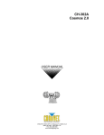
CA-8 & CA-8F Easy Controller (Optional)
The CA-8 Easy Controller is used only in master/slave mode. Connect the controller to the 1/4”
microphone jack in the first unit. The table below describes the different preset shows the CA-8 Controller
can command.
CA-8 & CA-8F BUTTONS
STAND BY
MODE
(LED off)
Sound
(LED blinks normal)
Sound
BLACKOUT
(LED on)
Slow/Sound
(LED blinks fast)
Position
FUNCTION
CA-8 Easy Controller & the
CA-8F Foot Controller
Fixture: All
Strobe
1. Gobo/color sync strobe
2. sync strobe
3. two light strobe
Fixture: 606DBR & 606DSR
(X/Y) moving patterns
(12 patterns user selectable)
Fixture: 625DCR
Chase Pattern selection
(6 patterns)
Fixture: All
Color/Gobo selection (Hold for gobo
change, tap for color change.)
Fixture: 606DBR & 606DSR
X/Y moving position, dimmer setting
Fixture: 625DCR
Dimmer setting
Note! All programmed movements are built into the fixtures and are triggered by the CA-8(F) controllers.
X/Y Moving Patterns for CA-8 Controller
ILS-606 & ILS-625 User Manual
13
2005-01-11/17:17
APPENDIX
DMX Primer
There are 512 channels in a DMX-512 connection. Channels may be assigned in any manner. A fixture
capable of receiving DMX-512 will require one or a number of sequential channels. The user must assign a
starting address on the fixture that indicates the first channel reserved in the controller. There are many
different types of DMX controllable fixtures and they all may vary in the total number of channels required.
Choosing a start address should be planned in advance. Channels should never overlap. If they do, this
will result in erratic operation of the fixtures whose starting address is set incorrectly. You can however,
control multiple fixtures of the same type using the same starting address as long as the intended result is
that of unison movement or operation. In other words, the fixtures will be slaved together and all respond
exactly the same.
DMX fixtures are designed to receive data through a serial Daisy Chain. A Daisy Chain connection is
where the DATA OUT of one fixture connects to the DATA IN of the next fixture. The order in which the
fixtures are connected is not important and has no effect on how a controller communicates to each fixture.
Use an order that provides for the easiest and most direct cabling. Connect fixtures using shielded two
conductor twisted pair cable with three pin XLR male to female connectors. The shield connection is pin 1,
while pin 2 is Data Negative (S-) and pin 3 is Data positive (S+). CHAUVET carries 3-pin XLR DMX
compliant cables, DMX-10 (33’), DMX-4.5 (15’) and DMX-1.5 (5’)
Figure 4 - DMX connector configuration
1
3
2
COMMON
1
3
INPUT
1
3
DMX +
2
2
DMX -
Resistance 120
ohm 1/4w between
pin 2 (DMX -) and
pin 3 (DMX +) of
the last fixture.
OUTPUT
Termination reduces signal errors and to
avoid signal transmission problems and
interference, it is always advisable to
connect a DMX signal terminator.
F I XT URE LI NKI NG
Note!
If you use a controller with a 5 pin DMX output connector, you will need to use a 5
pin to 3 pin adapter. CHAUVET Model No: DMX5M.
The chart below details a proper cable conversion:
3 PIN TO 5 PIN CONVERSION CHART
Conductor
3 Pin Female (output)
5 Pin Male (Input)
Ground/Shield
Pin 1
Pin 1
Data ( - )signal
Pin 2
Pin 2
Data ( + ) signal
Pin 3
Pin 3
Do not use
Do not use
Do not use
Do not use
ILS-606 & ILS-625 User Manual
14
2005-01-11/17:17
Appendix
DMX Channel Values (606DSR & 606DBR)
CHANNEL
VALUE
1
000 255
Pan
Left > Right ( 128 = center)
000 255
Tilt – 606DSR
Up > Down (128 = center)
000 009
010 120
121 134
135 245
246 255
Barrel Rotation - 606DBR
Stopped
Fast > Slow (counter-clockwise)
Stopped
Slow > Fast (clockwise)
Stopped
3
000 007
008 015
016 131
132 247
248 255
Shutter/Shaking
Blackout
Open
Slow > Fast (shutter)
Slow > Fast (shaking)
Open
4
000 015
016 031
032 047
048 063
064 079
080 095
096 111
112 127
128 255
Gobo
Open
Gobo 1
Gobo 2
Gobo 3
Gobo 4
Gobo 5
Gobo 6
Gobo 7
Slow > Fast (gobo scroll)
2
5
6
(normal)
000 012
013 025
026 038
039 051
052 063
064 076
077 089
090 102
103 115
116 127
128 255
FUNCTION
(CS)
000 007
008 015
016 022
023 030
031 037
038 045
046 052
053 060
061 067
068 075
076 082
083 090
091 097
098 105
106 112
113 120
121 127
128 255
000 009
010 120
121 134
135 245
246 255
Color (normal)
Open (white)
Green
Magenta
Light Blue
Yellow
Orange
Blue
UV Purple
Light Green
Pink
Slow > Fast (color
scroll)
CS (color split mode)
Open (white)
Green
Green + Magenta
Magenta
Magenta + Light Blue
Light Blue
Light Blue + Yellow
Yellow
Yellow + Orange
Orange
Orange + Blue
Blue
Blue + UV Purple
UV Purple
UV Purple + Light Green
Light Green
Pink
Slow > Fast (color scroll)
Gobo rotation
Stopped
Fast > Slow (counter clockwise)
Stopped
Slow > Fast (clockwise)
Stopped
Dimmer
Closed > Open
7
ILS-606 & ILS-625 User Manual
000 255
Dimmer (Version B) User Selectable {IdIN} function
{no} = Close > Open (0% to 100%)
{I} = Open > Close (100% to 0%)
15
2005-01-11/17:17
Appendix
DMX Channel Values (625DCR)
CHANNEL
VALUE
1
000 007
008 015
016 131
132 247
248 255
Shutter/Shaking
Blackout
Open
Slow > Fast (shutter)
Slow > Fast (shaking)
Open
2
000 015
016 031
032 047
048 063
064 079
080 095
096 111
112 127
128 255
Gobo
Open
Gobo 1
Gobo 2
Gobo 3
Gobo 4
Gobo 5
Gobo 6
Gobo 7
Slow > Fast (gobo scroll)
3
4
(normal)
000 012
013 025
026 038
039 051
052 063
064 076
077 089
090 102
103 115
116 127
128 255
FUNCTION
(CS)
000 007
008 015
016 022
023 030
031 037
038 045
046 052
053 060
061 067
068 075
076 082
083 090
091 097
098 105
106 112
113 120
121 127
128 255
000 009
010 120
121 134
135 245
246 255
Color (normal)
Open (white)
Green
Magenta
Light Blue
Yellow
Orange
Blue
UV Purple
Light Green
Pink
Slow > Fast (color scroll)
CS (color split mode)
Open (white)
Green
Green + Magenta
Magenta
Magenta + Light Blue
Light Blue
Light Blue + Yellow
Yellow
Yellow + Orange
Orange
Orange + Blue
Blue
Blue + UV Purple
UV Purple
UV Purple + Light Green
Light Green
Pink
Slow > Fast (color scroll)
Gobo rotation
Stopped
Fast > Slow (counter clockwise)
Stopped
Slow > Fast (clockwise)
Stopped
Dimmer
Closed > Open
5
ILS-606 & ILS-625 User Manual
000 255
Dimmer (Version B) User Selectable {IdIN} function
{no} = Close > Open (0% to 100%)
{I} = Open > Close (100% to 0%)
16
2005-01-11/17:17
Gobos
606DBR & 606DSR
Open
Dots Tunnel Broken Glass
Swirl
Cylinder
Frost Breakup
Triangle
4 Dots
Frost Breakup
3200°K
6600°K
625-DCR
Open
Dots Tunnel Broken Glass
Frost
Cylinder
Version (B) Models
The {IdIN} Dimmer Inverse function is available only on Version (B) models of these fixtures. The chart
below will help you determine the version of the fixture you may have. This is not a critical function; it is
simply an enhanced functionality which in the real world may not find much use. Never the less, we would
like to inform you of a possible discrepancy you may encounter with this manual regarding this function.
Version
Model No.
ILS-606DSR
A
ILS-606DBR
ILS-625DCR
B
ILS-606 & ILS-625 User Manual
Serial Number Range
CH-04085053 ~ CH-04085198
CH-04085049 ~ CH-04085052
3-04121209 ~ 3-04121408
3-04110901 ~ 3-04111000
CH-04085203 ~ CH-04085273
CH-04085199 ~ CH-04085202
3-04121459 ~ 3-04121558
CH-04085878 ~ CH-04085948
CH-04085874 ~ CH-04085877
C3-04121409 ~ 3-0412145
(all other serial numbers}
The serial number is located on the fixture’s label. The label can be found
at the rear of the fixture.
17
2005-01-11/17:17
Maintenance
To maintain optimum performance and minimize wear fixtures should be cleaned frequently. Usage and
environment are contributing factors in determining frequency. As a general rule, fixtures should be
cleaned at least twice a month. Dust build up reduces light output performance and can cause
overheating. This can lead to reduced lamp life and increased mechanical wear. Be sure to power off
fixture before conducting maintenance.
Unplug fixture from power. Use a vacuum or air compressor and a soft brush to remove dust collected on
external vents and internal components. Clean all glass when the fixture is cold with a mild solution of
glass cleaner or Isopropyl Alcohol and a soft lint free cotton cloth or lens tissue. Apply solution to the cloth
or tissue and drag dirt and grime to the outside of the lens. Gently polish optical surfaces until they are free
of haze and lint. Do not to touch the lamp glass when cleaning fixture. Oil and dirt can cause damage and
premature aging of the lamp. In the event that the lamp is touched or becomes dirty, clean the lamps with
an alcohol wipe.
The cleaning of internal and external optical lenses and/or mirrors must be carried out periodically to
optimize light output. Cleaning frequency depends on the environment in which the fixture operates: damp,
smoky or particularly dirty surrounding can cause greater accumulation of dirt on the unit’s optics. Clean
with soft cloth using normal glass cleaning fluid. - Always dry the parts carefully. - Clean the external optics
at least every 20 days. Clean the internal optics at least every 30/60 days.
Returns Procedure
Returned merchandise must be sent prepaid and in the original packing, call tags will not be issued.
Package must be clearly labeled with a Return Merchandise Authorization Number (RA #). Products
returned without an RA # will be refused. Call CHAUVET and request RA # prior to shipping the fixture. Be
prepared to provide the model number, serial number and a brief description of the cause for the return. Be
sure to properly pack fixture, any shipping damage resulting from inadequate packaging is the customer’s
responsibility. CHAUVET reserves the right to use its own discretion to repair or replace product(s). As a
suggestion, proper UPS packing or double-boxing is always a safe method to use.
Claims
Damage incurred in shipping is the responsibility of the shipper; therefore the damage must be reported to
the carrier upon receipt of merchandise. It is the customer's responsibility to notify and submit claims with
the shipper in the event that a fixture is damaged due to shipping. Any other claim for items such as
missing component/part, damage not related to shipping, and concealed damage, must be made within
seven (7) days of receiving merchandise.
ILS-606 & ILS-625 User Manual
18
2005-01-11/17:17
Appendix
General Troubleshooting
Applies to
Symptom
Solution(s)
Lights
Controllers
Dimmers
& Chaser
Auto shut off
Check fan thermal switch reset
Beam is very dim or not
bright
Clean optical system or replace lamp
Check 220/110v switch for proper setting
Breaker/Fuse keeps
blowing
Check total load placed on device
Chase is too slow
Check users manual for speed adjustment
Device has no power
Check for power on Mains.
Check device’s fuse. (internal and/or external)
Fixture is not responding
Check DMX Dip switch settings for correct addressing
Check DMX cables
Check polarity switch settings
Fixture is on but there is
no movement to the
audio
Make sure you have the correct audio mode on the control
switches. If audio provided via ¼” jack, make sure a live audio
signal exists
Adjust sound sensitivity knob
Lamps cuts off
sporadically
Possible bad lamp or fixture is overheating.
Lamp may be at end of its life.
Light will not come on
after power failure
Some discharge lamps require a cooling off period before the
electronics in the fixture can kick start it again, wait 5 to 10
minutes before powering up
Loss of signal
Use only DMX cables
Install terminator
Note: Keep DMX cables separated from power cables or black
lights.
Motor movements are
jerky or jumpy
Possible bad motor driver or sensors
Check polarity switch on controller
Moves slow
Check 220/110v switch for proper setting
No flash
Re-install bulb, may have shifted in shipping
No light output
Check slip ring & brushes for contact
Install bulb
Call service technician
Relay will not work
Check reset switch
Check cable connections
Remote does not work
Make sure connector is firmly connected to device
Stand alone mode
All CHAUVET lighting fixtures featuring stand-alone functions
do not require additional settings, simply power the fixture and
it will automatically enter into this mode
Unit wobbles when
rotating
Check for damages possibly incurred during shipping
ILS-606 & ILS-625 User Manual
Foggers
& Snow
19
2005-01-11/17:17
Appendix
Technical Specifications
WEIGHT & DIMENSIONS
(ILS-606DBR, ILS-606DSR) .......................................................................................................................
Length ............................................................................................................................ 695 mm (27.36 in)
Width .............................................................................................................................. 340 mm (13.39 in)
Height ............................................................................................................................... 250 mm (9.84 in)
Weight ................................................................................................................................ 15.4 Kg (34 lbs)
(ILS-625DCR) ..............................................................................................................................................
Length .............................................................................................................................. 360 mm (14.2 in)
Width ................................................................................................................................ 340 mm (13.4 in)
Height ................................................................................................................................. 250 mm (9.8 in)
Weight ................................................................................................................................ 13.2 Kg (29 lbs)
POWER
Switch-selectable power settings .................................................................... 115V 60 Hz or 230V 50 Hz
AC input ...............................................................................................................3 prongs IEC 60320 C14
European version...................................................................................................................... 240V 50 Hz
LAMPS
CHAUVET US-HSD-250 ........................................................................................ 2000 hr, 6000K, 250W
Philips MSD-250/2 .................................................................................................. 2000 hr, 6500K, 250W
Philips MSD-200 ..................................................................................................... 2000 hr, 5600K, 200W
GOBOS
Outside diameter ...........................................................................................................................26.8 mm
Image diameter..............................................................................................................................21.0 mm
Thickness ......................................................................................................................................... 0.2 mm
PHOTO OPTIC
Beam Angle ............................................................................................................................................14°
Pan (ILS-606)........................................................................................................................................180°
Tilt (ILS-606) ...........................................................................................................................................70°
THERMAL
Maximum ambient temperature .............................................................................................. 40° (104° F)
FUSE
Main.................................................................................................................20mm Glass 10A Fast Blow
CONTROL & PROGRAMMING
Data input....................................................................................................locking 3-pin XLR male socket
Data output ............................................................................................. locking 3-pin XLR female socket
Data pin configuration................................................................................. pin 1 shield, pin 2 (-), pin 3 (+)
Protocols ...........................................................................................................................DMX-512 USITT
DMX Channels (606xxx) ........................................................................................................................... 7
DMX Channels (625DCR) ......................................................................................................................... 5
ORDERING INFORMATION
Trackscan 250DBR-ILS™ Barrel Scanner .............................................................................ILS-606DBR
Trackscan 250DSR-ILS™ Mirror Scanner .............................................................................ILS-606DSR
Colortrack 250DCR-ILS™ Color Changer ............................................................................. ILS-625DCR
Fuse 10A 250V ....................................................................................................................P170FUSE010
OPTIONS
Easy Controller ....................................................................................................................................CA-8
Easy Foot Controller..........................................................................................................................CA-8F
Technical Support
Address:
Support (Email):
Telephone:
Fax:
Website:
ILS-606 & ILS-625 User Manual
Service Dept.
th
3000 N 29 Ct, Hollywood, FL 33020 (U.S.A.)
tech@chauvetlighting.com
(954) 929-1115 - (Press 4)
(954) 929-5560 - (Attention: Service)
http://www.chauvetlighting.com
20
2005-01-11/17:17