1
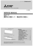
Home > Products > M Series > R410A Ceiling Concealed Ducted System > Inverter Heat Pump >
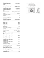
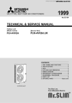
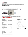
SEZ-KA60VA Inverter Heat Pump
R410A Ceiling Concealed Ducted System
Designed for homes, offices, restaurants or shops, the SEZ series operates at Model Info
low noise levels and is virtually invisible when installed within a suspended
ceiling. Its low unit height and lightweight design also helps to make
installation easier and more convenient.
Hover your mouse over the red icons below to view a description of each feature:
Dimensions
SEZ-KA60VA (Click to
enlarge).
SEZ-KA60VA Indoor Unit
Capacity (kW):
Heating (Nominal) (Low
- High)
6.90 (0.90 - 8.00)
Cooling (Nominal) (Low
- High)
5.50 (1.10 - 6.30)
Heating (UK) (Low High)
5.75 (0.75 - 6.65)
Cooling (UK) (Low High)
5.45 (1.10 - 6.25)
SHF R410A (Nominal)
0.75
COP / EER (Nominal)
2.82 / 2.81
Energy Label Heating /
Cooling
C/D
Width - mm
1100
Depth - mm
700
Height - mm
270
Weight - kg
33.5
Airflow (m3/min)
(Heating / Cooling) Lo-Hi
12-20 / 12-20
SUZ-KA60VA (Click to
enlarge).
[Print]
[Print]
External Static
Pressure Pa(mmAq) Lo-Hi
30(3)-50(5)
Noise (dBA) (Heating /
Cooling) - Lo-Hi
32-43 / 32-43
Pipe Size Gas mm (in)
15.88 (5/8)
Pipe Size Liquid mm
(in)
Electrical Supply
6.35 (1/4)
Fed by Outdoor Unit
Phase
Single
Fuse Rating (BS88) HRC (A)
6
Interconnecting Cable
No. Cores
4
Remote Controller Ref
PAR-21MAA
SUZ-KA60VA Outdoor Unit
Width - mm
840
Depth - mm
330
Height - mm
850
Weight - kg
53
Noise (dBA) (Heating /
Cooling)
Electrical Supply
Phase
52 / 52
220-240v, 50Hz
Single
Fuse Rating (BS88) - HRC
(A)
25
System Power Input (kW) Heating (Nominal)
2.45
System Power Input (kW) Cooling (Nominal)
1.96
System Power Input (kW) Heating (UK)
2.23
System Power Input (kW) Cooling (UK)
1.57
Starting Current (A)
10.4
System Running Current
(A) - Heating / Cooling
Mains Cable No. Cores
10.4 / 9
3
Max Pipe Length (m)
30
Max Height Difference (m)
15
Charge (kg) - 7m
1.8
OC321-A-1.qxp
05.2.24 8:54 AM
Page 1
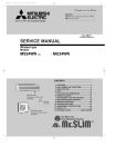
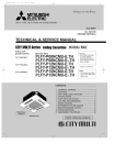
SPLIT-TYPE, HEAT PUMP AIR CONDITIONERS
No.OC321
TECHNICAL & SERVICE MANUAL
Indoor unit
[Model names]
[Service Ref.]
SEZ-KA35VA.TH
SEZ-KA50VA.TH
SEZ-KA60VA.TH
SEZ-KA35VA
SEZ-KA50VA
SEZ-KA60VA
Note :
•This manual does not cover
outdoor units. When servicing
outdoor units, please refer
to the service manual
No.OC322 together with this
manual.
CONTENTS
Model name
indication
INDOOR UNIT
TEMP.
ON/OFF
WIRED REMOTE
CONTROLLER
1. PART NAMES AND FUNCTIONS ········2
2. SPECIFICATIONS·································4
3. OUTLINES AND DIMENSIONS············8
4. WIRING DIAGRAM·······························9
5. REFRIGERANT SYSTEM DIAGRAM ······10
6. TROUBLESHOOTING ························11
7. DISASSEMBLY PROCEDURE···········15
8. PARTS LIST········································18
9. OPTIONAL PARTS ·············Back Cover
OC321-A-1.qxp
1
05.2.24 8:54 AM
Page 2
PART NAMES AND FUNCTIONS
Indoor Unit
SEZ-KA35VA.TH
SEZ-KA50VA.TH
SEZ-KA60VA.TH
Air outlet
Air outlet duct flange
Air inlet
(Selecting the either back side or bottom side)
Wired remote controller
On the controls are set, the same operation mode can be repeated by simply pressing the ON/OFF button.
● Operation buttons
Start/Stop button
Set Temperature buttons
Down
Fan Speed button
Up
Timer Menu button
(Monitor/Set button)
Filter
button
(<return sign> button)
Mode button (Return button)
TEMP.
ON/OFF
Set Time buttons
Service button (Clear button)
Back
Ahead
Test Run button
MENU
BACK
MONITOR/SET
ON/OFF
FILTER
DAY
CHECK TEST
Airflow Up/Down button
Timer On/Off button
(Set Day button)
PAR-21MAA
OPERATION
CLOCK
CLEAR
Louver button
Operation button)
(
To preceding operation
number.
Opening the
door.
Ventilation button
Operation button)
(
To next operation number.
2
OC321-A-1.qxp
05.2.24 8:54 AM
Page 3
● Display
“Sensor” indication
Displayed when the remote controller
sensor is used.
Day-of-Week
For purposes of this explanation,
all parts of the display are shown
as lit. During actual operation, only
the relevant items will be lit.
Shows the current day of the week.
Time/Timer Display
“Locked” indicator
Shows the current time, unless the simple or Auto Off
timer is set.
If the simple or Auto Off timer is set, shows the time
remaining.
Indicates that remote controller buttons have been locked.
Identifies the current operation
“Clean The Filter” indicator
Shows the operating mode, etc.
* Multilanguage display is supported.
Comes on when it is time to clean the
filter.
TIME SUN MON TUE WED THU FRI SAT
TIMER
Hr
ON
AFTER
FUNCTION
FILTER
˚F˚C
“Centrally Controlled” indicator
Indicates that operation of the remote controller has been prohibited by a master controller.
Timer indicators
AFTER OFF
ERROR CODE
˚F˚C
The indicator comes on if the corresponding timer is set.
WEEKLY
SIMPLE
AUTO OFF
ONLY1Hr.
Fan Speed indicator
Shows the selected fan speed.
“Timer Is Off” indicator
Indicates that the timer is off.
Temperature Setting
Shows the target temperature.
Up/Down Air Direction indicator
Room Temperature display
Shows the room temperature.
The indicator
shows the direction of the outcoming airflow.
Louver display
“One Hour Only” indicator
Indicates the action of the swing
louver. Does not appear if the
louver is stationary.
Displayed if the airflow is set to
weak and downward during COOL
or DRY mode. (Operation varies
according to model.)
The indicator goes off after one
hour, at which time the airflow direction also changes.
Ventilation indicator
Appears when the unit is running in
Ventilation mode.
(Power On indicator)
Indicates that the power is on.
Caution
● Only the Power display lights when the unit is stopped and power supplied to the unit.
● When power is turned ON for the first time the (Centrally controlled) display appears to go off momentarily but this is not a
malfunction.
● “NOT AVAILABLE” is displayed when the Air speed button are pressed.This indicates that this room unit is not equipped
with the fan direction adjustment function and the louver function.
● When power is turned ON for the first time, it is normal that “PLEASE WAIT” is displayed on the room temperature indication (For max. 2minutes). Please wait until this “PLEASE WAIT” indication disappear then start the operation.
3
OC321-A-1.qxp
2
05.2.24 8:54 AM
Page 4
SPECIFICATIONS
Indoor model
SEZ-KA35VA.TH
Function
Cooling
Electrical
data
Fan
motor
Special remarks
K /h
A
A
W
A(kW)
%
A
Winding
resistance (at20:)
"
Dimensions WoHoD
Weight
Air direction
Sound level (High/Low)
Fan speed (High/Low)
Fan speed regulator
External satatic pressure
Thermistor TH1 (at 25:)
Thermistor TH2 (at 25:)
Thermistor TH5 (at 25:)
mm
kg
dB(A)
rpm
Pa
k"
k"
k"
Cooling
Heating
Single phase
230V, 50Hz
780/600
10
0.40
60
—
Power supply
Capacity Air flow (High/Low)
Power outlet
Running current ✽1
Power input Rated frequency
Auxiliary heater
Power factor ✽1
Fan motor current ✽1
Model
SEZ-KA50VA.TH
93
Heating
Single phase
230V, 50Hz
1020/720
20
0.55
80
—
97
94
0.22
PK6V19-EF
WHT-BLK : 257 BLK-BLU : 20
BLU-YLW : 27
YLW-BRN : 14
BRN-RED : 51
1100o270o700
33.5
1
35/30
770/630
3
Std : 30 Max : 50
10
10
10
98
0.27
PK6V32-EF
WHT-BLK : 166
BLK-BLU : 52
BLU-YLW : 19
YLW-BRN : 8
BRN-RED : 40
1100o270o700
33.5
1
39/31
840/640
3
Std : 30 Max : 50
10
10
10
NOTE : Test conditions are based on ISO 5151
Cooling : Indoor D.B. 27: W.B. 19:
Outdoor D.B. 35: W.B. 24:
Heating : Indoor D.B. 20: W.B. 5:
Outdoor D.B. 7: W.B. 6:
Refrigerant piping length (one way): 5m
✽1 Measured under rated operating frequency.
Specifications and rating conditions of main electric parts
INDOOR UNIT
Item
Model
Indoor fan capacitor
Fuse
(C1)
SEZ-KA35VA.TH SEZ-KA50VA.TH SEZ-KA60VA.TH
SEZ-KA35/50VA.TH : 2.5+ 440V
(FUSE)
Varistor
Terminal block
(ZNR)
(TB)
SEZ-KA60VA.TH : 3.0+ 440V
250V 6.3A
ERZV10D471
TO OUTDOOR UNIT : 3P
Indoor fan motor thermal fuse
TO WIRED REMOTE CONTROLLER : 2P
145:i2:
4
OC321-A-1.qxp
05.2.24 8:54 AM
Page 5
Indoor model
SEZ-KA60VA.TH
Function
Cooling
Power supply
Special remarks
Fan
motor
Electrical
data
Capacity Air flow (High/Low)
Power outlet
Running current ✽1
Power input Rated frequency
Auxiliary heater
Power factor ✽1
Fan motor current ✽1
Model
Winding
resistance (at20:)
Dimensions WoHoD
Weight
Air direction
Sound level(High/Low)
Fan speed(High/Low)
Fan speed regulator
External satatic pressure
Thermistor TH1 (at 25:)
Thermistor TH2 (at 25:)
Thermistor TH5 (at 25:)
K /h
A
A
W
A(kW)
%
A
"
mm
kg
dB(A)
rpm
Pa
k"
k"
k"
Heating
Single phase
230V, 50Hz
1200/720
20
0.65
100
—
98
98
0.39
PK6V50-EF
WHT-BLK : 103
BLK-BLU : 57
BLU-YLW : 15
YLW-BRN : 7
BRN-RED : 29
1100o270o700
33.5
1
43/32
890/660
3
Std : 30 Max : 50
10
10
10
NOTE : Test conditions are based on ISO 5151
Cooling : Indoor D.B. 27: W.B. 19:
Outdoor D.B. 35: W.B. 24:
Heating : Indoor D.B. 20: W.B. 15:
Outdoor D.B. 7: W.B. 6:
Refrigerant piping length (one way): 5m
✽1 Measured under rated operating frequency.
5
OC321-A-1.qxp
05.2.24 8:54 AM
Page 6
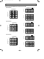
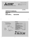
NOISE CRITERION CURVES
<50Hz>
<50Hz>
SEZ-KA35VA.TH
NOTCH SPL(dB)
High
35
Low
30
LINE
SEZ-KA50VA.TH
80
70
NC-70
60
NC-60
50
NC-50
40
NC-40
30
NC-30
APPROXIMATE
TERESHOLD OF
HEARING FOR
CONTINUOUS
NOISE
NC-20
OCTAVE BAND SOUND PRESSURE LEVEL, dB (0 dB = 0.0002 µbar)
OCTAVE BAND SOUND PRESSURE LEVEL, dB (0 dB = 0.0002 µbar)
LINE
90
90
20
NOTCH SPL(dB)
High
39
Low
31
80
70
NC-70
60
NC-60
50
NC-50
40
NC-40
30
NC-30
20
APPROXIMATE
TERESHOLD OF
HEARING FOR
CONTINUOUS
NOISE
NC-20
10
10
63
125
250
500
1000
2000
4000
63
8000
125
250
500
1000
2000
4000
8000
BAND CENTER FREQUENCIES, Hz
BAND CENTER FREQUENCIES, Hz
<50Hz>
SEZ-KA60VA.TH
NOTCH SPL(dB)
High
43
Low
32
LINE
OCTAVE BAND SOUND PRESSURE LEVEL, dB (0 dB = 0.0002 µbar)
90
UNIT
80
70
NC-70
60
NC-60
External static
pressure 30Pa
1.5m
50
NC-50
MICROPHONE
40
NC-40
30
NC-30
20
APPROXIMATE
TERESHOLD OF
HEARING FOR
CONTINUOUS
NOISE
NC-20
10
63
125
250
500
1000
2000
4000
8000
BAND CENTER FREQUENCIES, Hz
NOTE: The sound level is measured in an anechoic room where echoes are few, when compressor stops. The sound
may be bigger than displayed level under actual installation condition by surrounding echoes. The sound level
can be higher by about 2 dB than the displayed level during cooling and heating operation.
6
OC321-A-1.qxp
05.2.24 8:54 AM
Page 7
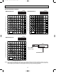
INDOOR FAN PERFORMANCE AND CORRECTED AIR FLOW
SEZ-KA35VA.TH
Corrected Air flow
Capacity
Input
Cooling
1.1
Correction factor
Fan Performance
Recommended range
60
0.8
1.3
40
20
0
0.9
5
10
15
20
25
20
25
Air flow (K/X)
Correction factor
External static pressure(Pa)
(1Pa = 0.1mmAq)
80
1.0
5 7
10
15
20
25
Heating
1.2
1.1
1.0
0.9
Air flow (K/X)
0.8
5
10
15
Air flow (K/X)
SEZ-KA50VA.TH
Corrected Airflow
Fan Performance
Correction factor
1.1
Recommended range
80
60
1.0
0.9
0.8
5
10
15
20
25
20
25
Air flow (K/X)
40
1.2
0
Heating
1.1
20
5
10
15
20
Correction factor
External static pressure(Pa)
(1Pa = 0.1mmAq)
Capacity
Input
Cooling
25
Air flow (K/X)
1.0
0.9
0.8
5
10
15
Air flow (K/X)
SEZ-KA60VA.TH
Corrected Air flow
Capacity
Input
Cooling
1.1
Correction factor
Fan Performance
Recommended range
60
1.0
0.9
0.8
10
15
20
25
30
25
30
Air flow (K/X)
40
1.3
Correction factor
External static pressure(Pa)
(1Pa = 0.1mmAq)
80
20
0
5
10
15
20
25
Air flow (K/X)
Heating
1.2
1.1
1.0
0.9
10
15
20
Air flow (K/X)
7
OC321-A-1.qxp
05.2.24 8:54 AM
3
Page 8
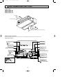
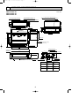
OUTLINES AND DIMENSIONS
Unit : mm
SEZ-KA35VA.TH
SEZ-KA50VA.TH
SEZ-KA60VA.TH
Air inlet (bottom side) dimensions
930
215
77
39 77.5 100
7x100=700
(Inlet size)
Electrical parts box
930
(Inlet size)
215
Select the either
back side or bottom side.
51
450
955
50
w
Air inlet
(rear side)
150
25
1016
240
27
50
PLATE (B) x 2
120
24-{2.9 holes
150
7x100=700
955
77.5 100
25
120
12.5
240
(Inlet size)
29
PLATE (A)
After installation, remove the
transportation support PLATE (B).
12.5
42
In case of bottom side suction,
mount the PLATE (A) on the rear side.
(Inlet size)
Air inlet (rear side) dimensions
700
Access door
bolt pitch
(10)
680
60 38
350
50 Suspension
1000
600
24-{2.9 holes
Service space
(It is necessary to maintain a working
service area from the ceiling.)
40
50
100
7x100=700
880
9 x 2-{2.9 holes
Air outlet duct flange
Air outlet
1070
Suspension bolt pitch
32.5
100
Wiring entry
Terminal block
Access door
Air outlet duct flange
94
25
108
75
2x2-{2.9
holes
Air inlet
(bottom side)
50
20
25
(10)
Electrical parts box
1100
w
170
Refrigerent pipe (liquid)
30
(Suspension bolt pitch)
Refrigerent pipe (gas)
20 or more
(1070)
270
Suspension bolt
M10 or 3/8
(procure locally)
80
Electrical parts box
Drain plug R1 (male)
350
Select the either back side or bottom side.
Models
SEZ-KA35VA
SEZ-KA50VA
SEZ-KA60VA
8
Refrigerent pipe
(liquid)
Refrigerent pipe
(gas)
{6.35mm
{9.52mm
flared connection
1/4F
{6.35mm
flared connection
1/4F
{6.35mm
flared connection
1/4F
flared connection
3/8F
{12.7mm
flared connection
1/2F
{15.88mm
flared connection
5/8F
OC321-A-1.qxp
05.2.24 8:54 AM
4
Page 9
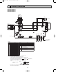
WIRING DIAGRAM
SEZ-KA35VA.TH
SEZ-KA50VA.TH
SEZ-KA60VA.TH
MF
TB4
BRN
3
4
5
6
7
8
1
2
3
4
5
6
7
8
BLU
2
YLW
TO OUTDOOR
UNIT
S3
1
ORN
C1
BLU
YLW
BLK
ORN
RED
WHT
S1
S2
RED
P.B
1 2 3 AC220-240V
CNSK(RED)
KA60
ON
OFF
12345
2
3
4
5
6
12345
ORN
BLU
3
BLU
1
WHT
(FAN)
FAN
7
RED
WHT
KA50
ON
OFF
1
RED
KA35
BRN
SW2
ON
OFF
BLU
BLK
MODELS
WHT
<fig:w1>
RED
1
(POWER
BOARD)
CNDK
FUSE
ORN
(POWER)
CND
3
1
I.B
TRANS
3
BLU
(CONTROL)
CN3C
1 2 DC13.1V
CN2S(WHT)
12345
X6
X6
X5
ZNR
X4
WHT
(POWER
BOARD)
CN2D
X4
SW3
ON
OFF
1
2
BLK
WHT
LED3
12345
LED1
CN2L
BLK
RED
(2 PHASE) (INTAKE)
CN20
CN29
12345
1
CN51
CN32
CN41
2
1
2
CN90
See fig:w1
LED2
WHT
(LIQUID)
CN21
1
2
BLU
(REMOCON)
CN22
1
2
BLU
SW2
ON
OFF
BLU
SWE
ON
OFF
X5
TB15
1
2
TH5
[LEGEND]
SYMBOL
P.B
NAME
INDOOR POWER BOARD
SYMBOL
C1
NAME
CAPACITOR(FAN MOTOR)
INDOOR CONTROLLER BOARD
MF
FAN MOTOR
CN2L
CONNECTOR(LOSSNAY)
TB4
TERMINAL BLOCK(INDOOR/OUTDOOR CONNECTING LINE)
CN32
CONNECTOR(REMOTE SWITCH)
CN41
CONNECTOR(HA TERMINAL-A)
CN51
CENTRALLY CONTROL
CN90
CONNECTOR(WIRELESS)
FUSE
FUSE(T6.3AL250V)
LED1
POWER SUPPLY(I.B)
LED2
POWER SUPPLY(I.B)
I.B
LED3
TRANSMISSION(INDOOR-OUTDOOR)
SW2
SWITCH(CAPACITY CODE)
SW3
SWITCH(MODE SELECTION)
SWE
SWITCH(EMERGENCY OPERATION)
X4
RELAY(FAN MOTOR LL)
X5
RELAY(FAN MOTOR Lo)
X6
RELAY(FAN MOTOR Hi)
ZNR
VARISTOR
TERMINAL BLOCK(REMOTE CONTROLLER
TB15
TRANSMISSION LINE)
ROOM TEMP.THERMISTOR
TH1
(0°C/15kΩ,25°C/5.4kΩ DETECT)
PIPE TEMP.THERMISTOR/LIQUID
TH2
(0°C/15kΩ,25°C/5.4kΩ DETECT)
COND./EVA.TEMP.THERMISTOR
TH5
(0°C/15kΩ,25°C/5.4kΩ DETECT)
NOTES: 1.Since the outdoor side electric wiring may change be sure to
check the outdoor unit electric wiring for servicing.
2.Indoor and outdoor connecting wires are made with polarities,make
wiring matching terminal numbers(S1,S2,S3).
3.Symbols used in wiring diagram above are,
:Connector,
:Terminal(block).
4.Since the indoor fan motor(MF) is connected with 50Hz power,
if 60Hz power is used, change the wiring connection showing
fig:w2.
<fig:w2>
Indoor Fan Motor(MF)
for 60Hz
BLUE
50
YELLOW
60
BLUE
wFor details on how to operate self-diagnosis
refer to the technical manuals etc.
9
TH1
TH2
}
TO MA-REMOTE
CONTROLLER
DC8.7-13V
OC321-A-1.qxp
5
05.2.24 8:54 AM
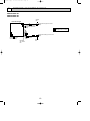
Page 10
REFRIGERANT SYSTEM DIAGRAM
SEZ-KA35VA.TH
SEZ-KA50VA.TH
SEZ-KA60VA.TH
Strainer
#50
Heat exchanger
Refrigerant GAS pipe connection
(Flare)
Condenser/evaporator
temperature thermistor
(TH5)
Refrigerant flow in cooling
Refrigerant flow in heating
Refrigerant LIQUID pipe connection
(Flare)
Pipe temperature
thermistor/liquid
(TH2)
Room temperature
thermistor (TH1)
Distributor
with strainer
#50
Strainer
#50
10
OC321-A-1.qxp
05.2.24 8:54 AM
6
Page 11
TROUBLESHOOTING
6-1. Cautions on troubleshooting
(1) Before troubleshooting, check the followings:
1 Check the power supply voltage.
2 Check the indoor/outdoor connecting wire for mis-wiring.
(2) Take care the followings during servicing.
1 Before servicing the air conditioner, be sure to first turn off the remote controller to stop the main unit, and then turn
off the breaker.
2 When removing the indoor controller board, hold the edge of the board with care NOT to apply stress on the
components.
3 When connecting or disconnecting the connectors, hold the housing of the connector. DO NOT pull the lead wires.
6-2. Self-check function
Wired remote controller
(1) Turn on the power.
(2) Press the [CHECK] button twice.
(3) Set refrigerant address with [TEMP] button
if system control is used.
(4) Press the [ON/OFF] button to stop the
self-check.
A CHECK button
B Refrigerant address
C TEMP button
D IC : Indoor unit
OC : Outdoor unit
E Check code
B
E D
˚C
˚C
SIMPLE
TEMP.
C
MENU
BACK
PAR-21MAA
MONITOR/SET
ON/OFF
ON/OFF
FILTER
DAY
CLOCK
CHECK TEST
OPERATION
CLEAR
A
• For description of each check code, refer to the following table.
1 Check code
P1
P2
P9
E6,E7
P4
P5
P6
EE
P8
E0, E3~E5
E1, E2
Fb
E9
UP
U3,U4
UF
U2
U1,Ud
U5
U8
U6
U7
U9,UH
Others
Symptom
Intake sensor error
Pipe (TH2) sensor error
Pipe (TH5) sensor error
Indoor/outdoor unit communication error
Drain sensor error
Drain pump error
Freeing/Overheating safeguard operation
Communication error between indoor and outdoor units
Pipe temperature error
Remote controller transmission error
Remote controller control board error
Indoor unit control system error (memory error, etc.)
Indoor/outdoor unit communication error (Transmitting error) (Outdoor unit)
Compressor overcurrent interruption
Open/short of outdoor unit thermistors
Compressor overcurrent interruption (When compressor locked)
Abnormal high discharging temperature/49C worked/insufficient refrigerant
Abnormal high pressure (63H worked)/Overheating safeguard operation
Abnormal temperature of heat sink
Outdoor unit fan safeguard stop
Compressor overcurrent interruption/Abnormal of power module
Abnormality of super heat due to low discharge temperature
Abnormality such as overvoltage or voltage shortage and abnormal synchronous signal to main circuit
/Current sensor error
Other errors (Refer to the technical manual for the outdoor unit.)
• On wired remote controller.
1 Check code displayed in the LCD.
11
Remark
For details, check the LED display
of the outdoor controller board.
As for outdoor unit, refer to
service manual OC322.
OC321-A-1.qxp
05.2.24 8:54 AM
Page 12
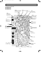
6-3. Test point diagram
6-3-1. Indoor power board
SEZ-KA35VA.TH
SEZ-KA50VA.TH
SEZ-KA60VA.TH
CN2S
Connect to the indoor controller board (CN2D)
1 (+))
Between 1 to 3 12.6-13.7V DC (Pin1
CNSK
Connect to the indoor controller board
(CNDK)
Between 1 to 3 220-240V AC
12
OC321-A-1.qxp
05.2.24 8:54 AM
Page 13
6-3-2. Indoor controller board
SEZ-KA35VA.TH
SEZ-KA50VA.TH
SEZ-KA60VA.TH
LED3
Transmission
(Indoor/outdoor)
–
+
+
CN3C
Transmission
(Indoor/outdoor)
(0~24V DC)
LED1
Power supply LED2
Power supply
(I.B)
(R.B)
}
CN2D
Connector to the indoor
power board (CN2S)
(12.5~13.7V DC)
Non polarity
–
CND
Power
supply input
(220~240V AC)
CN22
Remote controller
connecting wire
(10.4~14.6V DC)
CN20
Room temperature
thermistor (TH1)
}
CN21
Pipe temperature
thermistor/Liquid
(TH2)
FUSE
(6.3A 250V)
CNDK
Connect to the indoor
power board (CNSK)
(220~240V AC)
CN29
Condenser/evaporator
temperature thermistor
(TH5)
CN41
Connector
(HA terminal-A)
CN51
Centrally control
CN2L
Connector
(LOSSNAY)
FAN
Fan motor output
Jumper connector
J11~J15
Unit setting
SW3
SWE
Mode selection Emergency operation
13
SW2
Capacity setting
OC321-A-1.qxp
05.2.24 8:54 AM
Page 14
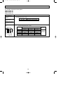
6-4. Trouble criterion of main parts
SEZ-KA35VA.TH
SEZ-KA50VA.TH
SEZ-KA60VA.TH
Part name
Check method and criterion
Room temperature
thermistor
(TH1)
Measure the resistance with a tester.
(Part temperature 10°C ~ 30°C)
Pipe temperature
thermistor/liquid
(TH2)
Condenser/evaporator
temperature thermistor
(TH5)
Normal
Abnormal
8kΩ~20kΩ
Opened or short-circuited
Measure the resistance between the terminals with a tester.
(Coil wiring temperature 10°C ~ 30°C)
Indoor fan motor
(MF)
Normal
P
BLK BLU YLW BRN RED ORN
WHT
P : Thermal fuse
KA35VA
KA50VA
KA60VA
GRN
WHT-BLK
270~244Ω
157~175Ω
97~109Ω
YLW
BLK-BLU
19~20Ω
49~55Ω
54~60Ω
BLU-YLW
25~29Ω
18~20Ω
14~16Ω
YLW-BRN
13~15Ω
7~9Ω
6~8Ω
BRN-RED
48~54Ω
38~42Ω
277~31Ω
145 ± 2˚C
14
Abnormal
Opened or
short-circuited
OC321-A-1.qxp
05.2.24 8:54 AM
7
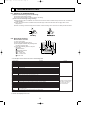
Page 15
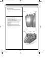
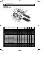
DISASSEMBLY PROCEDURE
SEZ-KA35VA.TH
SEZ-KA50VA.TH
SEZ-KA60VA.TH
OPERATING PROCEDURE
PHOTOS
1. Removing the electrical parts
(1) Remove the 2 screws and the electrical parts cover.
(See Photo 1.)
● Indoor controller board (I.B)
● Terminal block (TB4,TB15)
● Indoor power board (P.B)
● Fan motor capacitor (C1)
(See Photo 2.)
Photo 1.
Service panel
(Pipe temperature
thermistor / liquid)
Electrical
parts cover
Drain
pan
Set screws
Service panel
Front panel
Set screws
(Condenser / evaporator
(for
drain
pan)
temperature thermistor)
2. Removing the pipe temperature thermistor (TH2)
Photo 2.
Terminal
Terminal
block (TB15) block (TB4)
Indoor
controller box
(1) Remove the electrical parts cover. (Refer to 1.)
(2) Remove the 2 screws and the service panel.
(See Photo 3.)
(3) Remove the thermistor (TH2) from the holder.
(See Photo 4.)
(4) Remove the connector (CN21) from the indoor
controller board and pull the white wire of thermistor
(TH2) out.
Fan motor
capacitor
3. Removing the condenser / evaporator temperature
thermistor (RT13)
(1) Remove the electrical parts cover. (Refer to 1.)
(2) Remove the 2 screws and the service panel.
(See Photo 3.)
(3) Remove the thermistor (TH5) from the holder.
(See Photo 4.)
(4) Remove the connector (CN29) from the indoor
controller board and pull the black wire of thermistor
(TH5) out.
Indoor controller board
Photo 4.
Photo 3.
Screws
Pipe temperature
thermistor / liquid
(TH2)
Service
panel
Screws
15
Indoor power board
Condenser / evaporator
temperature thermistor (TH5)
OC321-A-1.qxp
05.2.24 8:54 AM
Page 16
PHOTOS
OPERATING PROCEDURE
4. Removing the room temperature thermistor (TH1)
Photo 5.
(1) Remove the electrical parts cover. (Refer to 1.)
(2) Remove the 12 screws and the front panel at fan side.
(See Photo 1.)
(3) Remove the thermistor (TH1) from the separator panel.
(See Photo 6.)
(4) Disconnect the connector (CN20)from the indoor
controller board and pull the lead wire of
thermistor (TH1) out.
Claws
Claws
Photo 6.
Motor bands
Screws
Room temperature
thermistor (TH1)
5. Removing the sirocco fan and the fan motor (MF).
(1) Remove the electrical parts cover. (Refer to 1.)
(2) Remove the 12 screws and the front panel at fan side.
(See Photo 1.)
(3) Disconnect the connector of the fan motor lead wire.
(See Photo 2.)
(4) Undo the 4 claws and remove the fan claws.(down side)
<Either left or right> (See Photo 5.)
(5) Remove the motor bands.
<A screw each on left and right.> (See Photo 5.)
(6) Disconnect the earth wire from the fan motor leg.
(See Photo 7.)
(7) Remove the fan motor and the sirocco fan by assembly.
(See Photo 7.)
(8) Unscrew the setting screw and remove the sirocco fan.
<Either left or right> (See Photo 7.)
Photo 7.
Set screw
Earth wire
16
Fan motor
Separator
panel
Fan casing
Fan motor
Fan casing
OC321-A-1.qxp
05.2.24 8:54 AM
Page 17
PHOTOS
OPERATING PROCEDURE
6. Removing the drain pan
(1) Unscrew each set screw on the right and left, and
remove the drain pan pushing it toward the the back.
(See Photo 1.)
Photo 8.
Screws
7. Removing the heat exchanger
(1) Remove the drain pan. (Refer to 1.)
(2) Remove the 16 screws and the Under flange at heat
exchanger side. (See Photo 8.)
(3) Remove the 4 screws of heat exchanger.( 2 screws
each on left and right) (See Photo 9.)
(4) Remove the thermistor (TH2) from the holder.
(Refer to 2.)
(5) Remove the thermistor (TH5) from the holder.
(Refer to 3.)
(6) Remove the 3 screws and the service panel.
(See Photo 9.)
(7) Put the heat exchanger down to the fan motor and
pull it toward you.
(See Photo 9.)
Under flange
Photo 9.
Screws
for heat exchanger
Service
panel
Heat exchanger
17
Screws
for service panel
OC321-A-1.qxp
8
05.2.24 8:54 AM
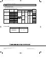
Page 18
PARTS LIST
INDOOR UNIT
STRUCTURAL PARTS
SEZ-KA35VA.TH
SEZ-KA50VA.TH
SEZ-KA60VA.TH
15
14
13
12
11
1
10
2
3
9
8
7
5
4
6
Part number that is circled is not shown in the illustration.
Q'ty/set
No.
Parts No.
Parts name
Specification
Price
Wiring RecomRemarks Diagram mended
(Drawing No.) Symbol Q'ty Unit Amount
KA35VA.TH KA50VA.TH KA60VA.TH
SEZ-
1 E07 039 086 LEFT SIDE PANEL
1
1
1
2 E07 039 500 SIROCCO FAN
2
2
2
3 E02 179 505 FAN MOTOR RUBBER MOUNT
2
2
2
E07 039 300 FAN MOTOR
PK6V19-EF
4 E07 040 300 FAN MOTOR
PK6V32-EF
E07 041 300 FAN MOTOR
PK6V50-EF
1
<2PCS/SET>
MF
1
MF
1
MF
TH1
5 E07 159 308 ROOM TEMPERATURE THERMISTOR
1
1
1
6 E07 039 000 FRONT PANEL
1
1
1
7 E07 039 700 DRAIN PAN
1
1
1
CONDENSER / EVAPORATOR
TEMPERATURE THERMISTOR
1
1
1
TH5
9 E07 159 307 PIPE TEMPERATURE THERMISTOR / LIQUID
1
1
1
TH2
8 E07 154 309
E07 143 620 INDOOR HEAT EXCHANGER
1
10 E07 144 620 INDOOR HEAT EXCHANGER
1
E07 145 620 INDOOR HEAT EXCHANGER
1
11 E07 039 808 RIGHT LEG
2
2
2
12 E07 143 085 RIGHT SIDE PANEL
1
1
1
13 E07 143 293 SEPARATOR ASSY
1
1
1
14 E07 039 809 LEFT LEG
2
2
2
15 E07 039 290 BASE
1
1
1
18
OC321-A-1.qxp
05.2.24 8:54 AM
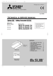
Page 19
INDOOR UNIT
ELECTRICAL PARTS
SEZ-KA35VA.TH
SEZ-KA50VA.TH
SEZ-KA60VA.TH
6
5
TEMP.
ON/OFF
1
2
TO REMOTE
CONTROLLER
7
8
S1
S2
TO OUTDOOR
UNIT
4
S3
9
3
1
2
Part numbers that is circled is not shown in the illustration.
Q'ty/set
No.
Parts No.
Parts name
Specification
Price
Wiring RecomRemarks
Diagram mended
SEZUnit Amount
(Drawing No.) Symbol Q'ty
KA35VA.TH KA50VA.TH KA60VA.TH
E07 159 447 INDOOR CONTROLLER BOARD
1
1 E07 160 447 INDOOR CONTROLLER BOARD
I.B
1
E07 161 447 INDOOR CONTROLLER BOARD
2 E02 661 385 VARISTOR
3 E07 006 382 FUSE
250V/6.3A
4 E07 154 440 INDOOR POWER BOARD
5
E02 063 351 FAN MOTOR CAPACITOR 2.5+
I.B
1
I.B
1
1
1
ZNR
1
1
1
FUSE
1
1
1
P.B
1
1
E02 138 351 FAN MOTOR CAPACITOR 3.0+
C1
1
C1
6 E07 156 375 TERMINAL BLOCK
2P
1
1
1
TB15
7 E07 162 375 TERMINAL BLOCK
3P
1
1
1
TB4
8 E07 159 426 REMOTE CONTROLLER
1
1
1
R.B
9 E07 018 089 REMOTE CONTROLLER CABLE
1
1
1
10 E07 039 449 CONTROLLER COVER
1
1
1
19
OC321-A-1.qxp
9
05.2.24 8:54 AM
Page 20
OPTIONAL PARTS
9-1. REFRIGERANT PIPES
The air conditioner has flared connections its indoor and outdoor sides.
Please use the optional extension pipe as follows.
Pipe size O.D.mm (in.)
Applied unit
Models
Pipe length
Cross-section
SEZ-KA35VA.TH
SEZ-KA50VA.TH
SEZ-KA60VA.TH
MAC-680PI
MAC-681PI
MAC-682PI
MAC-683PI
MAC-684PI
MAC-670PI
MAC-671PI
MAC-672PI
MAC-673PI
MAC-674PI
MAC-860PI
MAC-861PI
MAC-862PI
MAC-863PI
MAC-864PI
3m
5m
7m
10m
15m
3m
5m
7m
10m
15m
3m
5m
7m
10m
15m
A-Gas
B-liquid
{9.52
C
Insulation
D
{27
(3/8)
{21
Additional
refrigerant
charge
R410A (g)
0
60
150
300
0
{12.7
{6.35
(1/2)
(1/4)
{31
{27
40
100
200
0
{15.88
40
100
200
(5/8)
9-2. AIR FILTER
Applied unit
SEZ-KA35VA.TH
SEZ-KA50VA.TH
SEZ-KA60VA.TH
Models
PAC - 1000 FT
HEAD OFFICE : MITSUBISHI DENKI BLDG., 2-2-3, MARUNOUCHI, CHIYODA-KU, TOKYO 100-8310, JAPAN
CCopyright 2005 MITSUBISHI ELECTRIC ENGINEERING CO., LTD.
Distributed in Feb. 2005 No. OC321 PDF 8
Made in Japan.
New publication, effective Feb. 2005.
Specifications subject to change without notice.