1
PA-T3 Serial Port Adapter Installation
and Configuration
Product Number: PA-T3(=) and PA-2T3(=)
Platforms Supported: Cisco 7500 Series, Cisco 7000 Series,
Cisco 7100 Series, Cisco 7200 Series, Cisco uBR7200
Series, Catalyst 5000 Series Switches
Access Registrar, AccessPath, Any to Any, AtmDirector, CCDA, CCDE, CCDP, CCIE, CCNA, CCNP, CCSI, CD-PAC, the Cisco logo, Cisco Certified Internetwork Expert logo,
CiscoLink, the Cisco Management Connection logo, the Cisco NetWorks logo, the Cisco Powered Network logo, Cisco Systems Capital, the Cisco Systems Capital logo, Cisco Systems
Networking Academy, the Cisco Technologies logo, ConnectWay, ControlStream, Fast Step, FireRunner, GigaStack, IGX, JumpStart, Kernel Proxy, MGX, Natural Network Viewer,
NetSonar, Network Registrar, Packet, PIX, Point and Click Internetworking, Policy Builder, Precept, RouteStream, Secure Script, ServiceWay, SlideCast, SMARTnet, StreamView, The
Cell, TrafficDirector, TransPath, ViewRunner, VirtualStream, VisionWay, VlanDirector, Workgroup Director, and Workgroup Stack are trademarks; Changing the Way We Work, Live,
Play, and Learn, Empowering the Internet Generation, The Internet Economy, and The New Internet Economy are service marks; and Asist, BPX, Catalyst, Cisco, Cisco IOS, the Cisco
IOS logo, Cisco Systems, the Cisco Systems logo, the Cisco Systems Cisco Press logo, Enterprise/Solver, EtherChannel, EtherSwitch, FastHub, FastLink, FastPAD, FastSwitch, IOS,
IP/TV, IPX, LightStream, LightSwitch, MICA, NetRanger, Registrar, StrataView Plus, Stratm, TeleRouter, and VCO are registered trademarks of Cisco Systems, Inc. in the U.S. and certain
other countries. All other trademarks mentioned in this document are the property of their respective owners. (9905R)
PA-T3 Serial Port Adapter Installation and Configuration
Copyright © 1996, 1997, 1999, Cisco Systems, Inc.
All rights reserved.
Corporate Headquarters
Cisco Systems, Inc.
170 West Tasman Drive
San Jose, CA 95134-1706
USA
http://www.cisco.com
Tel: 408 526-4000
800 553-NETS (6387)
Fax: 408 526-4100
Text Part Number: 78-4721-07
Preface
This preface describes how to find additional information on the PA-T3 and PA-2T3 serial port
adapters and other Cisco products, services, and documentation. This preface contains the following
sections:
•
•
•
•
•
Objectives, page v
Organization, page v
Related Documentation, page vi
Cisco Connection Online, page vii
Cisco Documentation CD-ROM, page viii
Objectives
This document describes how to install and configure the PA-T3 serial port adapter (PA-T3[=] and
PA-2T3[=]) in the following platforms:
•
Cisco 7200 series routers—which consist of the two-slot Cisco 7202, four-slot Cisco 7204 and
Cisco 7204VXR, and six-slot Cisco 7206 and Cisco 7206VXR
•
•
Cisco uBR7200 series universal broadband routers
•
•
Cisco 7100 series routers—which consist of the Cisco 7120 and Cisco 7140
Second-generation Versatile Interface Processor (VIP2) in Cisco 7500 series routers and
Cisco 7000 series routers with the Cisco 7000 Series Route Switch Processor (RSP7000) and
Cisco 7000 Series Chassis Interface (RSP7000CI)
Catalyst Route Switch Module (RSM)/VIP2 in Catalyst 5000 series switches
Organization
This document is organized into the following chapters:
Section
Title
Description
Chapter 1
Overview
Describes the PA-T3 port adapter and
describes its LED displays, cables,
and receptacles.
Chapter 2
Preparing for Installation
Describes safety considerations, tools
required, and procedures you should
perform before the actual
installation.
Preface v
Related Documentation
Section
Title
Description
Chapter 3
VIP2 and the PA-T3 Port Adapter
Provides instructions for installing
the PA-T3 port adapter on a VIP2
interface processor installed in
Cisco 7500 or Cisco 7000 series
routers.
Chapter 4
Catalyst RSM/VIP2 and the PA-T3
Port Adapter
Provides instructions for installing
the PA-T3 port adapter on a
Catalyst RSM/VIP2 installed in
Catalyst 5000 series switches.
Chapter 5
Cisco 7200 Series and the
PA-T3 Port Adapter
Provides instructions for installing
the PA-T3 port adapter in a Cisco
7200 series router.
Chapter 6
Cisco uBR7200 Series and the
PA-T3 Port Adapter
Provides instructions for installing
the PA-T3 port adapter in the
Cisco uBR7200 series universal
broadband router.
Chapter 7
Cisco 7100 Series and the PA-T3
Port Adapter
Provides information on the PA-T3
and its use in Cisco 7100 series
routers.
Chapter 8
Configuring the PA-T3 Interfaces
Provides instructions for configuring
your port adapter on the supported
platforms. The instructions given in
this chapter apply to all supported
platforms described in this document.
Related Documentation
Your router and the Cisco IOS software running on it contain extensive features and functionality,
which are documented in the following resources:
•
For Cisco IOS software configuration information and support, refer to the modular
configuration and modular command reference publications in the Cisco IOS software
configuration documentation set that corresponds to the software release installed on your
Cisco hardware.
Note You can access Cisco IOS software configuration and hardware installation and
maintenance documentation on the World Wide Web at http://www.cisco.com,
http://www-china.cisco.com, or http://www-europe.cisco.com.
•
For hardware installation and maintenance information on Cisco 7000 series and Cisco 7500
series routers, and the VIP2, refer to the following publications:
— The installation and configuration guide that shipped with your Cisco 7000 series or
Cisco 7500 series router
— Second-Generation Versatile Interface Processor (VIP2) Installation and Configuration (for
VIP2 users only)
•
For hardware installation and maintenance information on the Catalyst 5000 series switches and
the Catalyst RSM/VIP2, refer to the following publications:
— The installation and configuration guide that shipped with your Catalyst 5000 series switches
vi
PA-T3 Serial Port Adapter Installation and Configuration
Cisco Connection Online
— Route Switch Module Catalyst VIP2-15 and VIP2-40 Installation and Configuration Note
(Document Number 78-4780-01) which shipped with your Catalyst RSM/VIP2
•
For hardware installation and maintenance information on Cisco 7100 series routers, refer to the
Cisco 7100 Series VPN Router Installation and Configuration Guide publication that shipped
with your Cisco 7100 series router.
•
For information on setting up a Virtual Private Network, see the Cisco 7100 Series VPN
Configuration Guide.
•
For hardware installation and maintenance information on the Cisco 7200 VXR routers, refer to
the Cisco 7200 VXR Installation and Configuration Guide publication that shipped with your
Cisco 7200 VXR router.
•
For hardware installation and maintenance information on the Cisco 7200 routers, refer to the
following publications that shipped with your router:
— Cisco 7202 Installation and Configuration Guide
— Cisco 7204 Installation and Configuration Guide
— Cisco 7206 Installation and Configuration Guide
•
For hardware installation and maintenance information on the Cisco uBR7200 series routers,
refer to the Cisco uBR72xx Universal Broadband Router Installation and Configuration Guide
that shipped with your Cisco uBR7200 series router.
•
For international agency compliance, safety, and statutory information for WAN interfaces for
Cisco 7500 series, Cisco 7000 series, Cisco 7200 series, Cisco 7100 series, and Cisco uBR7200
series routers, refer to the following publications:
— Regulatory Compliance and Safety Information for the Cisco 7500 Series Routers
— Regulatory Compliance and Safety Information for the Cisco 7000 Series Routers
— Regulatory Compliance and Safety Information for the Cisco 7200 Series Routers
— Regulatory Compliance and Safety Information for the Cisco 7100 Series Routers
— Regulatory Compliance and Safety Information for the Cisco ubr72xx Universal Broadband
Router
Note The regulatory compliance and safety information documentation listed above applies to the
Catalyst 5000 series switches and the Catalyst RSM/VIP2.
•
For port adapter hardware and memory configuration guidelines for Cisco 7200 series routers,
refer to the document Cisco 7200 Series Port Adapter Hardware Configuration Guidelines.
•
To view Cisco documentation or obtain general information about the documentation, refer to the
Documentation CD-ROM, see the “Cisco Connection Online” section, or call customer service
at 800 553-6387 or 408 526-7208. Customer service hours are 5:00 a.m. to 6:00 p.m. Pacific
time, Monday through Friday (excluding Cisco-observed holidays). You can also send e-mail to
cs-rep@cisco.com.
Cisco Connection Online
Cisco Connection Online (CCO) is Cisco Systems’ primary, real-time support channel. Maintenance
customers and partners can self-register on CCO to obtain additional information and services.
Preface vii
Cisco Documentation CD-ROM
Available 24 hours a day, 7 days a week, CCO provides a wealth of standard and value-added
services to Cisco’s customers and business partners. CCO services include product information,
product documentation, software updates, release notes, technical tips, the Bug Navigator,
configuration notes, brochures, descriptions of service offerings, and download access to public and
authorized files.
CCO serves a wide variety of users through two interfaces that are updated and enhanced
simultaneously: a character-based version and a multimedia version that resides on the World Wide
Web (WWW). The character-based CCO supports Zmodem, Kermit, Xmodem, FTP, and Internet
e-mail, and it is excellent for quick access to information over lower bandwidths. The WWW version
of CCO provides richly formatted documents with photographs, figures, graphics, and video, as well
as hyperlinks to related information.
You can access CCO in the following ways:
WWW: http://www.cisco.com
WWW: http://www-europe.cisco.com
WWW: http://www-china.cisco.com
Telnet: cco.cisco.com
Modem: From North America, 408 526-8070; from Europe, 33 1 64 46 40 82. Use the following
terminal settings: VT100 emulation; databits: 8; parity: none; stop bits: 1; and connection rates up
to 28.8 kbps.
For a copy of CCO’s Frequently Asked Questions (FAQ), contact cco-help@cisco.com. For
additional information, contact cco-team@cisco.com.
If you are a network administrator and need personal technical assistance with a Cisco product that
is under warranty or covered by a maintenance contract, contact Cisco’s Technical Assistance Center
(TAC) at 800 553-2447, 408 526-7209, or tac@cisco.com. To obtain general information about
Cisco Systems, Cisco products, or upgrades, contact 800 553-6387, 408 526-7208, or
cs-rep@cisco.com.
Cisco Documentation CD-ROM
Cisco documentation and additional literature are available in a CD-ROM package, which ships with
your product. The Documentation CD-ROM, a member of the Cisco Connection Family, is updated
monthly. Therefore, it might be more current than printed documentation. To order additional copies
of the Documentation CD-ROM, contact your local sales representative or call customer service.
The CD-ROM package is available as a single package or as an annual subscription. You can also
access Cisco documentation on the World Wide Web at http://www.cisco.com,
http://www-china.cisco.com, or http://www-europe.cisco.com.
If you are reading Cisco product documentation on the World Wide Web, you can submit comments
electronically. Click Feedback in the toolbar and select Documentation. After you complete the
form, click Submit to send it to Cisco. We appreciate your comments.
viii
PA-T3 Serial Port Adapter Installation and Configuration
C H A P TER
1
Overview
This chapter describes the one-port PA-T3 and two-port PA-2T3 serial port adapters. This chapter
contains the following sections:
•
•
•
Port Adapter Overview, page 1-1
PA-T3 Serial Port Adapter Features, page 1-2
Management Information Base, page 1-3
Port Adapter Overview
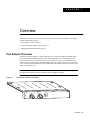
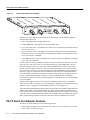
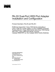
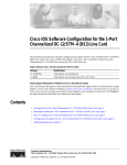
The PA-T3 serial port adapter is a single-width, one-port or two-port module that integrates data
service unit (DSU) functionality into the Cisco router. It provides one or two high-speed serial
PA-T3 interfaces on Cisco 7100 series routers, Cisco 7200 series routers, Cisco uBR7200 series
routers, on the second-generation Versatile Interface Processor (VIP2) in all Cisco 7000 series and
Cisco 7500 series routers, and on the Catalyst RSM/VIP2 in the Catalyst 5000 series switches. (See
Figure 1-1 and Figure 1-2.)
Note Port adapters have a handle attached, but this handle is occasionally not shown in figures in
this publication to allow a full view of detail on the port adapter’s faceplate.
One-Port PA-T3 Serial Port Adapter
LL
AIS
OO
F
H10041
FE
RC
TR
XM
VR
RC
AB
LE
D
LK
RF
RL
DS3 SERIAL
EN
Figure 1-1
Overview 1-1
PA-T3 Serial Port Adapter Features
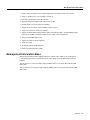
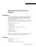
Figure 1-2
Two-Port PA-2T3 Serial Port Adapter
TR
XM
H10062
LL
AIS
OO
F
LL
AIS
OO
F
RC
VR
LK
FE
RF
RL
RC
LK
FE
RF
RL
RC
TR
XM
RC
VR
EN
AB
LE
D
DS3 SERIAL
The PA-T3 serial port adapter can be installed in the following slots on the hardware platforms
described in this document:
•
•
•
VIP2—Port adapter slot 0 and port adapter slot 1
•
Cisco 7200 series routers—Port adapter slot 1 and slot 2 of the Cisco 7202; port adapter slot 1
through slot 4 of the Cisco 7204 and Cisco 7204VXR; port adapter slot 1 through slot 6 of the
Cisco 7206 and Cisco 7206VXR
•
Cisco uBR7200 series routers—Port adapter slot 1 and slot 2 of the Cisco uBR7246; port adapter
slot 1 of the Cisco uBR7223
Catalyst RSM/VIP2—Port adapter slot 0 and port adapter slot 1
Cisco 7100 series routers—Port adapter slot 3 in the Cisco 7120 series and port adapter slot 4 in
the Cisco 7140 series
The one-port PA-T3 serial port adapter provides two network interfaces per VIP2 for Cisco 7000
series and Cisco 7500 series routers, two network interfaces per Catalyst RSM/VIP2, and one
high-speed interface on the Cisco 7200 series and Cisco uBR7200 series routers. The two-port
PA-2T3 serial port adapter provides four network interfaces per VIP2 for Cisco 7000 series and
Cisco 7500 series routers, four network interfaces for the Catalyst RSM/VIP2, and two high-speed
interfaces on the Cisco 7200 series and Cisco uBR7200 series routers. Serial network interfaces
reside on modular port adapters, which provide a direct connection between the high-speed bus in
the router and the external networks. The PA-T3 serial port adapter provides a full-duplex
synchronous serial PA-T3 interface for transmitting and receiving data at rates of up to 34 megabits
per second (Mbps).
The port adapter supports both 16- and 32-bit cyclic redundancy checks (CRCs). The default is
16-bit CRCs; to enable 32-bit CRCs, you use a configuration command. For a description of the CRC
function, see the “Configuring Cyclic Redundancy Checks” section on page 8-13.
The VIP2 and Catalyst RSM/VIP2 support online insertion and removal (OIR), but individual port
adapters with a VIP2 or Catalyst RSM/VIP2 do not support OIR. To replace port adapters in the
Cisco 7000 series and Cisco 7500 series routers, and the Catalyst 5000 series switches, you must first
remove the VIP2 or Catalyst RSM/VIP2 from the chassis and then replace port adapters as required.
OIR is supported for port adapters in the Cisco 7200 series and Cisco uBR7200 series routers.
PA-T3 Serial Port Adapter Features
The PA-T3 serial port adapter provides the following features:
•
1-2
Single-width port adapter for the VIP2 in all Cisco 7000 series, Cisco 7100 series, Cisco 7500
series, and Cisco 7200 series routers
PA-T3 Serial Port Adapter Installation and Configuration
Management Information Base
•
•
•
•
•
•
•
•
Single-width port adapter for the Catalyst RSM/VIP2 in all Catalyst 5000 series switches
•
•
•
•
•
Support for DS3 MIB (RFC 1407)
Single- or double-port T3 rate (45 Mbps) connectivity
Full-duplex synchronous serial DS3 interface
High-speed High-Level Data Link Control (HDLC) data
Integrated data service unit (DSU) functionality
Support for 16- and 32-bit cyclic redundancy checks (CRCs)
Support for C-bit, M13, and bypass framing
Support for ATM-Data Exchange Interface (DXI), Frame Relay, HDLC, Switched Multimegabit
Data Service (SMDS), and Point-to-Point Protocol (PPP) serial encapsulations
Support for remote and local loopback
B3ZS line coding
Scrambling and bandwidth reduction
Online insertion and removal (OIR)
Management Information Base
Management Information Base (MIB) attributes are readable and writable across the Integrated
Local Management Interface (ILMI) through use of the Simple Network Management Protocol
(SNMP).
The one-port PA-T3 serial port adapter supports MIB-II (RFC 1213) and the DS3 interface MIB
(RFC 1407).
The two-port PA-2T3 serial port adapter supports MIB-II (RFC 1213) and the DS3 interface MIB
(RFC 1407).
Overview 1-3
Management Information Base
1-4
PA-T3 Serial Port Adapter Installation and Configuration
C H A P TER
2
Preparing for Installation
This chapter describes the general equipment, safety, and site preparation requirements for installing
the PA-T3 port adapters.
•
•
•
•
•
•
•
Parts and Tools Required, page 2-1
Software and Hardware Requirements, page 2-2
PA-T3 Port Adapter LEDs, page 2-3
PA-T3 Receptacles and Cables, page 2-5
Interoperability Guidelines for PA-T3 Serial Port Adapter DSUs, page 2-5
Safety Guidelines, page 2-6
FCC Class A Compliance, page 2-8
Parts and Tools Required
You need the following tools and parts to install a port adapter. If you need additional equipment,
contact a service representative for ordering information.
•
PA-T3 serial port adapter and one of the following:
— VIP2-15(=), VIP2-20=, VIP2-40(=), or VIP2-50(=) motherboard
— Catalyst RSM/VIP2-15(=) or Catalyst RSM/VIP2-40(=) motherboard
— Cisco 7100 series router with at least one available port adapter slot
— Cisco 7200 series router with at least one available port adapter slot
— Cisco uBR7200 series router with at least one available port adapter slot
•
•
•
75-ohm coaxial serial interface cables
Number 1 Phillips screwdriver and a 3/16-inch flat-blade screwdriver
Your own ESD-prevention equipment or the disposable grounding wrist strap included with all
upgrade kits, field-replaceable units (FRUs), and spares
Preparing for Installation 2-1
Software and Hardware Requirements
Software and Hardware Requirements
Table 2-1 lists the minimum Cisco IOS software release required to use the PA-T3 and the
PA-2T3 serial port adapters in supported router platforms.
Table 2-1
PA-T3 Port Adapter Software Requirements
Platforms
Recommended Minimum Cisco IOS Release
Cisco 7000 and Cisco 7500 series
PA-T3
PA-2T3
• With VIP2-15(=) or VIP2-40(=)
Cisco IOS Release 11.1(13)CA or a later
release of Cisco IOS Release 11.1 CA
Cisco IOS Release 11.1(16)CA or a later
release of Cisco IOS Release 11.1 CA
• With VIP2-50(=)
Cisco IOS Release 11.1(14)CA or a later
release of Cisco IOS Release 11.1 CA
Cisco IOS Release 11.1(16)CA or a later
release of Cisco IOS Release 11.1 CA
• Cisco 7204VXR and Cisco 7206VXR
Cisco IOS Release 12.0(2)XE2 or a later
release of Cisco IOS Release 12.0 XE
Cisco IOS Release 12.0(3)T or a later release
of Cisco IOS Release 12.0 T
Cisco IOS Release 12.0(2)XE2 or a later
release of Cisco IOS Release 12.0 XE
Cisco IOS Release 12.0(3)T or a later release
of Cisco IOS Release 12.0 T
• Cisco 7204 and Cisco 7206
Cisco IOS Release 11.1(16)CA or a later
release of Cisco IOS Release 11.1 CA
Cisco IOS Release 11.1(16)CA or a later
release of Cisco IOS Release 11.1 CA
• Cisco 7202
Cisco IOS Release 11.1(19)CC1 or a later
release of Cisco IOS Release 11.1 CC
Cisco IOS Release 11.3(4)AA or a later
release of Cisco IOS Release 11.3 AA
Cisco IOS Release 11.1(19)CC1 or a later
release of Cisco IOS Release 11.1 CC
Cisco IOS Release 11.3(4)AA or a later
release of Cisco IOS Release 11.3 AA
Cisco IOS Release 12.0(2)XA or a later
release of Cisco IOS Release 12.0 XA
Cisco IOS Release 12.0(2)XA or a later
release of Cisco IOS Release 12.0 XA
Cisco 7200 series
Cisco uBR7200 series
• Cisco uBR7246 and Cisco uBR7223
Cisco 7100 Series
• Cisco 7120 series and Cisco 7140 series
Cisco IOS Release 12.0(4)XE or a later
release of Cisco IOS Release 12.0 XE
Cisco IOS Release 12.0(5)T or a later release
of Cisco IOS Release 12.0 T
Catalyst 5000 series switches
• With Catalyst RSM/VIP2-15(=) or
Catalyst RSM/VIP2-40(=)
Cisco IOS Release 12.0(4)T or a later release
of Cisco IOS Release 12.0T
Cisco IOS Release 12.0(4)T or a later release
of Cisco IOS Release 12.0T
Caution The VIP2 requires that the host Cisco 7000 series router have the RSP7000 and RSP7000CI
installed. The VIP2 does not operate properly with the Route Processor (RP), Switch Processor (SP), or
Silicon Switch Processor (SSP) installed in the host Cisco series router.
The PA-T3 serial port adapter is considered a high-bandwidth port adapter; therefore, and at a
minimum, Cisco recommends that the PA-T3 serial port adapter be installed on the VIP2-15 or
Catalyst RSM/VIP2 motherboard (with 1 MB of SRAM and 8 MB of DRAM). Installation of the
PA-T3 serial port adapter on the VIP2-10 (with 512 KB of SRAM and 8 MB of DRAM) is not
recommended.
2-2
PA-T3 Serial Port Adapter Installation and Configuration
PA-T3 Port Adapter LEDs
Note The VIP2 and Catalyst RSM/VIP2 supports online insertion and removal (OIR), but
individual port adapters do not. To replace port adapters in the Cisco 7000 series and Cisco 7500
series routers, and the Catalyst 5000 series switches, you must first remove the VIP2 or
Catalyst RSM/VIP2 from the chassis and then replace port adapters as required. OIR is supported
for port adapters in the Cisco 7100 series, Cisco 7200 series, and Cisco uBR7200 series routers. Port
adapters have a handle attached, but this handle is occasionally not shown in illustrations in this
publication to allow a full view of detail on the port adapter’s faceplate.
In the Cisco 7000 series, Cisco 7100 series, Cisco 7500 series, and Cisco uBR7200 series routers,
and the Catalyst 5000 series switches, there are no restrictions on slot locations or sequence;
however, in the Cisco 7200 series routers, there are specific configuration guidelines that must be
observed for high-bandwidth port adapters.
For specific Cisco 7200 series routers hardware configuration information and for memory
configuration guidelines, refer to the document Cisco 7200 Series Port Adapter Hardware
Configuration Guidelines, which shipped with your Cisco 7200 series chassis and is also available
on the Cisco Connection Documentation, Enterprise Series CD-ROM.
To determine if your Cisco 7000 series, Cisco 7100 series, Cisco 7500 series, Cisco 7200 series, or
Cisco uBR7200 series router, or Catalyst RSM/VIP2, is compatible with the PA-T3 serial port
adapter, use the show version command to display the current hardware configuration of the router,
including the system software version that is currently loaded and running. You can check the
version of the default ROM image by removing the board and checking the ROM labels, or by
configuring the interface or system software to boot from ROM, restarting the system, and using the
show version command to check the running version.
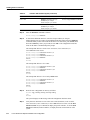
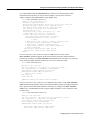
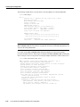
Use the show version command to display the current system software version. In the following
example, the running system software is Release 11.1(16)CA.
Router> show version
Cisco Internetwork Operating System Software
IOS (tm) GS Software, Version 11.1(16)CA
Synced to mainline version: 11.1(10.5)
Copyright (c) 1986-1997 by cisco Systems, Inc.
Compiled Thu 22-May-97 14:32
If your system lacks the required system software and microcode, contact a customer service
representative for upgrade information.
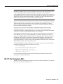
PA-T3 Port Adapter LEDs
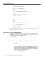
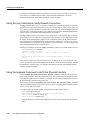
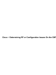
The PA-T3 has one status LED and six uplink port status LEDs (RCLK, FERF, OOF, AIS, RL, and
LL) for the serial T3 port. (See Figure 2-1.)
Preparing for Installation 2-3
PA-T3 Port Adapter LEDs
LEDs on the PA-T3 Serial Port Adapter—Partial Front View
H10040
RL
LK
FE
RF
DS3 SERIAL
LL
RC
F
AI
S
OO
VR
XM
TR
EN
RC
AB
LE
D
Figure 2-1
LEDs
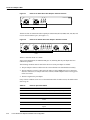
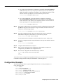
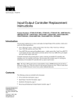
The PA-2T3 has one status LED and six uplink port status LEDs (RCLK, FERF, OOF, AIS, RL, and
LL) for each serial PA-T3 port. (See Figure 2-2.)
RL
RF
FE
RC
RL
LK
RF
FE
RC
DS3 SERIAL
H10063
F
LL
OO
S
AI
F
LL
AI
OO
S
XM
TR
VR
RC
LE
AB
EN
LK
LEDs on the PA-2T3 Serial Port Adapter—Partial Front View
D
Figure 2-2
LEDs
Table 2-2 describes the PA-T3’s LEDs.
After system initialization, the Enabled LED goes on, indicating that the port adapter has been
enabled for operation.
The following conditions must be met before the PA-T3 serial port adapter is enabled:
•
•
The port adapter contains a valid microcode version that has been downloaded successfully.
•
The bus recognizes the port adapter.
The port adapter is correctly connected to the VIP2 or Catalyst RSM/VIP2 (Cisco 7000 series
and Cisco 7500 series,or Catalyst 5000 series switches) and the midplane and is receiving power
in the Cisco router.
If any of these conditions is not met or if the initialization fails for other reasons, the enabled LED
does not go on.
Table 2-2
LEDs for Uplink Port Status
LED
Color
State
Description
ENABLED
Green
On
Indicates that port adapter is ready for operation.
RCLK
Green
On
Indicates that a receive clock has been detected.
FERF
Yellow
On
Indicates that Framer detected Far End Receive
Failure.
OOF
Yellow
On
Indicates that Framer detected Out of Frame.
AIS
Yellow
On
Indicates that Framer detected Alarm Indication
Signal.
RL
Yellow
On
Indicates that port is in remote loopback mode.
Uplink Port Status
2-4
PA-T3 Serial Port Adapter Installation and Configuration
PA-T3 Receptacles and Cables
LED
Color
State
Description
ENABLED
Green
On
Indicates that port adapter is ready for operation.
Yellow
On
Indicates that port is in local loopback mode.
Uplink Port Status
LL
PA-T3 Receptacles and Cables
The PA-T3 port adapter serial interface cable, which is a 75-ohm coaxial cable, connects your router
to a T3 serial network. Serial cables conform to EIA/TIA-612 and EIA/TIA-613 specifications. The
serial ports on the PA-T3 serial port adapter are considered to be data terminal equipment (DTE)
devices.
On a single PA-T3 serial port adapter, there are one or two T3 serial ports, each with two connectors
(receive and transmit), where you connect the Cisco 75-ohm coaxial cable. The 75-ohm coaxial
cable (Cisco part number CAB-ATM-DS3/E3) for the PA-T3 serial port adapter is available only
from Cisco Systems; it is not available from outside commercial cable vendors.
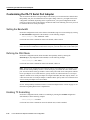
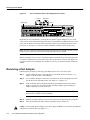
The Cisco PA-T3 75-ohm coaxial cable (see Figure 2-3) is available only in 10-foot (3.05-meter)
lengths. The typical maximum distance between stations for PA-T3 transmissions is
1300 feet (396 meters).
Figure 2-3
PA-T3 Serial Port Adapter Cable
BNC plug
BNC plug
H3399
75-ohm coaxial cabling
You can test the data terminal equipment-to-data circuit-terminating equipment (DTE-to-DCE)
cable connection by using the loopback dte command. See the “Using the loopback Command to
Verify the Physical Interface” section on page 8-24 for more information.
Interoperability Guidelines for PA-T3 Serial Port Adapter DSUs
The PA-T3 serial port adapter supports several types of integrated DSUs. Table 2-3 lists the feature
compatibilities of the PA-T3 serial port adapter DSUs.
Table 2-3
Feature Compatibilities of PA-T3 Serial Port Adapter DSUs
DSU
Full Rate
Support
Scrambling
Support
Subrate
Support
MDL1 Support
DL3100
Yes
Yes
Yes
No
Yes2
No
Yes
No
Kentrox
Yes
Yes
Larscom
Yes
Yes
2
1 MDL=Maintenance Digital Link.
2 PA-T3 serial port adapters support either scrambling or Kentrox subrate, not both at the same time.
Preparing for Installation 2-5
Safety Guidelines
Safety Guidelines
Following are safety guidelines that you should follow when working with any equipment that
connects to electrical power or telephone wiring.
Warning This warning symbol means danger. You are in a situation that could cause bodily injury. Before
you work on any equipment, be aware of the hazards involved with electrical circuitry and be familiar with
standard practices for preventing accidents. To see translations of the warnings that appear in this publication,
refer to the Regulatory Compliance and Safety Information document that accompanied this device.
Waarschuwing Dit waarschuwingssymbool betekent gevaar. U verkeert in een situatie die
lichamelijk letsel kan veroorzaken. Voordat u aan enige apparatuur gaat werken, dient u zich bewust
te zijn van de bij elektrische schakelingen betrokken risico's en dient u op de hoogte te zijn van
standaard maatregelen om ongelukken te voorkomen. Voor vertalingen van de waarschuwingen die
in deze publicatie verschijnen, kunt u het document Regulatory Compliance and Safety Information
(Informatie over naleving van veiligheids- en andere voorschriften) raadplegen dat bij dit toestel is
ingesloten.
Varoitus Tämä varoitusmerkki merkitsee vaaraa. Olet tilanteessa, joka voi johtaa ruumiinvammaan.
Ennen kuin työskentelet minkään laitteiston parissa, ota selvää sähkökytkentöihin liittyvistä
vaaroista ja tavanomaisista onnettomuuksien ehkäisykeinoista. Tässä julkaisussa esiintyvien
varoitusten käännökset löydät laitteen mukana olevasta Regulatory Compliance and Safety
Information -kirjasesta (määräysten noudattaminen ja tietoa turvallisuudesta).
Attention Ce symbole d'avertissement indique un danger. Vous vous trouvez dans une situation
pouvant causer des blessures ou des dommages corporels. Avant de travailler sur un équipement,
soyez conscient des dangers posés par les circuits électriques et familiarisez-vous avec les
procédures couramment utilisées pour éviter les accidents. Pour prendre connaissance des
traductions d’avertissements figurant dans cette publication, consultez le document Regulatory
Compliance and Safety Information (Conformité aux règlements et consignes de sécurité) qui
accompagne cet appareil.
Warnung Dieses Warnsymbol bedeutet Gefahr. Sie befinden sich in einer Situation, die zu einer
Körperverletzung führen könnte. Bevor Sie mit der Arbeit an irgendeinem Gerät beginnen, seien Sie
sich der mit elektrischen Stromkreisen verbundenen Gefahren und der Standardpraktiken zur
Vermeidung von Unfällen bewußt. Übersetzungen der in dieser Veröffentlichung enthaltenen
Warnhinweise finden Sie im Dokument Regulatory Compliance and Safety Information
(Informationen zu behördlichen Vorschriften und Sicherheit), das zusammen mit diesem Gerät
geliefert wurde.
Avvertenza Questo simbolo di avvertenza indica un pericolo. La situazione potrebbe causare
infortuni alle persone. Prima di lavorare su qualsiasi apparecchiatura, occorre conoscere i pericoli
relativi ai circuiti elettrici ed essere al corrente delle pratiche standard per la prevenzione di incidenti.
La traduzione delle avvertenze riportate in questa pubblicazione si trova nel documento Regulatory
Compliance and Safety Information (Conformità alle norme e informazioni sulla sicurezza) che
accompagna questo dispositivo.
Advarsel Dette varselsymbolet betyr fare. Du befinner deg i en situasjon som kan føre til
personskade. Før du utfører arbeid på utstyr, må du vare oppmerksom på de faremomentene som
elektriske kretser innebærer, samt gjøre deg kjent med vanlig praksis når det gjelder å unngå ulykker.
Hvis du vil se oversettelser av de advarslene som finnes i denne publikasjonen, kan du se i
dokumentet Regulatory Compliance and Safety Information (Overholdelse av forskrifter og
sikkerhetsinformasjon) som ble levert med denne enheten.
2-6
PA-T3 Serial Port Adapter Installation and Configuration
Electrical Equipment Guidelines
Aviso Este símbolo de aviso indica perigo. Encontra-se numa situação que lhe poderá causar danos
físicos. Antes de começar a trabalhar com qualquer equipamento, familiarize-se com os perigos
relacionados com circuitos eléctricos, e com quaisquer práticas comuns que possam prevenir
possíveis acidentes. Para ver as traduções dos avisos que constam desta publicação, consulte o
documento Regulatory Compliance and Safety Information (Informação de Segurança e Disposições
Reguladoras) que acompanha este dispositivo.
¡Advertencia! Este símbolo de aviso significa peligro. Existe riesgo para su integridad física. Antes
de manipular cualquier equipo, considerar los riesgos que entraña la corriente eléctrica y
familiarizarse con los procedimientos estándar de prevención de accidentes. Para ver una traducción
de las advertencias que aparecen en esta publicación, consultar el documento titulado Regulatory
Compliance and Safety Information (Información sobre seguridad y conformidad con las
disposiciones reglamentarias) que se acompaña con este dispositivo.
Varning! Denna varningssymbol signalerar fara. Du befinner dig i en situation som kan leda till
personskada. Innan du utför arbete på någon utrustning måste du vara medveten om farorna med
elkretsar och känna till vanligt förfarande för att förebygga skador. Se förklaringar av de varningar
som förkommer i denna publikation i dokumentet Regulatory Compliance and Safety Information
(Efterrättelse av föreskrifter och säkerhetsinformation), vilket medföljer denna anordning.
Electrical Equipment Guidelines
Follow these basic guidelines when working with any electrical equipment:
•
Before beginning any procedures requiring access to the chassis interior, locate the emergency
power-off switch for the room in which you are working.
•
•
Disconnect all power and external cables before moving a chassis.
•
Do not perform any action that creates a potential hazard to people or makes the equipment
unsafe. Carefully examine your work area for possible hazards such as moist floors, ungrounded
power extension cables, and missing safety grounds.
Do not work alone when potentially hazardous conditions exist and never assume that power has
been disconnected from a circuit; always check.
Telephone Wiring Guidelines
Use the following guidelines when working with any equipment that is connected to telephone
wiring or to other network cabling:
•
•
Never install telephone wiring during a lightning storm.
•
Never touch uninsulated telephone wires or terminals unless the telephone line has been
disconnected at the network interface.
•
Use caution when installing or modifying telephone lines.
Never install telephone jacks in wet locations unless the jack is specifically designed for wet
locations.
Preparing for Installation 2-7
FCC Class A Compliance
Preventing Electrostatic Discharge Damage
Electrostatic discharge (ESD) damage, which can occur when electronic cards or components are
improperly handled, results in complete or intermittent failures. Port adapters and processor modules
consist of printed circuit boards that are fixed in metal carriers. Electromagnetic interference (EMI)
shielding and connectors are integral components of the carrier. Although the metal carrier helps to
protect the board from ESD, use a preventive antistatic strap during handling.
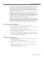
Following are guidelines for preventing ESD damage:
•
•
•
Always use an ESD wrist or ankle strap and ensure that it makes good skin contact.
•
When removing a component, use any available ejector levers or captive installation screws to
release the bus connectors from the backplane or midplane.
•
Handle carriers by available handles or edges only; avoid touching the printed circuit boards or
connectors.
•
Place a removed board component-side-up on an antistatic surface or in a static shielding
container. If you plan to return the component to the factory, immediately place it in a static
shielding container.
•
Avoid contact between the printed circuit boards and clothing. The wrist strap only protects
components from ESD voltages on the body; ESD voltages on clothing can still cause damage.
•
Never attempt to remove the printed circuit board from the metal carrier.
Connect the equipment end of the strap to an unfinished chassis surface.
When installing a component, use any available ejector levers or captive installation screws to
properly seat the bus connectors in the backplane or midplane. These devices prevent accidental
removal, provide proper grounding for the system, and help to ensure that bus connectors are
properly seated.
Caution For safety, periodically check the resistance value of the antistatic strap. The measurement should
be between 1 and 10 megohms (Mohm).
FCC Class A Compliance
This equipment has been tested and found to comply with the limits for a Class A digital device,
pursuant to part 15 of the FCC rules. These limits are designed to provide reasonable protection
against harmful interference when the equipment is operated in a commercial environment. This
equipment generates, uses, and can radiate radio-frequency energy and, if not installed and used in
accordance with the instruction manual, may cause harmful interference to radio communications.
Operation of this equipment in a residential area is likely to cause harmful interference, in which
case users will be required to correct the interference at their own expense.
You can determine whether your equipment is causing interference by turning it off. If the
interference stops, it was probably caused by the Cisco equipment or one of its peripheral devices.
If the equipment causes interference to radio or television reception, try to correct the interference
by using one or more of the following measures:
•
•
•
2-8
Turn the television or radio antenna until the interference stops.
Move the equipment to one side or the other of the television or radio.
Move the equipment farther away from the television or radio.
PA-T3 Serial Port Adapter Installation and Configuration
FCC Class A Compliance
•
Plug the equipment into an outlet that is on a different circuit from the television or radio. (That
is, make certain the equipment and the television or radio are on circuits controlled by different
circuit breakers or fuses.)
Note The PA-T3 serial port adapter has been designed to meet these requirements. Modifications
to this product that are not authorized by Cisco Systems, Inc., could void the various approvals and
negate your authority to operate the product.
Preparing for Installation 2-9
FCC Class A Compliance
2-10
PA-T3 Serial Port Adapter Installation and Configuration
C H A P TER
3
VIP2 and the PA-T3 Port Adapter
This chapter provides information on the PA-T3 port adapter and its use on the VIP2 in Cisco 7000
series and Cisco 7500 series routers. This chapter contains the following sections:
•
•
•
Overview, page 3-1
Removing a Port Adapter, page 3-4
Installing a Port Adapter, page 3-5
Overview
The PA-T3 serial port adapter is used on the VIP2 in Cisco 7000 series and Cisco 7500 series routers
and can be installed in either port adapter slot 0 or slot 1 on the VIP2 motherboard.
Note You can have up to three T3 serial interfaces on a VIP2 motherboard. Cisco recommends a
configuration of one PA-T3 serial port adapter (with one T3 serial interface) and one PA-2T3 serial
port adapter (with two serial interfaces) for a total of three T3 serial interfaces per VIP2.
Figure 3-1 shows two one-port PA-T3 serial port adapters installed in port adapter slot 0 and slot 1
on a VIP2-15 or VIP2-40.
VIP2 and the PA-T3 Port Adapter 3-1
Overview
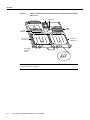
Figure 3-1
VIP2-15 or VIP2-40 with One-Port PA-T3 Serial Port Adapters in Port Adapter
Slots 0 and 1
CPU
Bus connector
Boot ROM
U6
SRAM
DIMM U5
U4
DRAM
SIMMs
U2
PA-T3 in port
adapter slot 0
PA-T3 in port
adapter slot 1
LK
VR
C
R
C
R
TR
F
R
FE
L
DS3 SERIAL
D
F
O
O
LL
VR
AB
EN
AIS
LK
LE
R
XM
C
R
C
R
TR
DS3 SERIAL
F
R
FE
L
24335
D
LE
AB
EN
R
XM
AIS
F
O
O
LL
Port adapter
handles not
shown
LK
C
R
F
S
AI
O
O
F
R
FE
L
R
LL
Note Port adapters have a handle attached, but this handle is not shown to allow a full view of detail
on each port adapter’s faceplate.
3-2
PA-T3 Serial Port Adapter Installation and Configuration
Overview
Figure 3-2 shows two one-port PA-T3 port adapters installed in port adapter slots 0 and 1 on a
VIP2-50.
Figure 3-2
VIP2-50 with One-Port PA-T3 Port Adapters in Port Adapter Slots 0 and 1
CPU
Boot ROM
Bus connector
SRAM
daughter
card
SDRAM DIMM
D
LK
LE
VR
AB
EN
C
R
C
R
TR
F
R
FE
L
DS3 SERIAL
D
F
O
O
LL
VR
AB
EN
AIS
LK
LE
R
XM
C
R
C
R
TR
DS3 SERIAL
F
R
FE
L
R
XM
AIS
F
O
O
LL
24336
PA-T3 in
port adapter
slot 1
PA-T3 in
port adapter
slot 0
Port adapter handles not shown
LK
C
R
F
S
AI
O
O
F
R
FE
L
R
LL
Depending on the circumstances, you might need to install a new port adapter on a VIP2
motherboard or replace a failed port adapter in the field. In either case, you need a number 1 Phillips
screwdriver, an antistatic mat on which you can place the removed interface processor, and an
antistatic container in which you can place a failed port adapter for shipment back to the factory.
Note The PA-T3 serial port adapter can be installed on a VIP2-15, VIP2-20, or VIP2-40
motherboard; however, installation on the VIP2-10 is not recommended.
Caution To prevent system problems, do not remove port adapters from the VIP2 motherboard or
attempt to install other port adapters on the VIP2 motherboard while the system is operating. To
install or replace port adapters, first remove the VIP2 from its interface processor slot.
Note Each port adapter circuit board is mounted to a metal carrier and is sensitive to ESD damage.
The following procedures should be performed by a Cisco-certified service provider only. The VIP2
supports online insertion and removal (OIR), but individual port adapters do not. To replace port
adapters, you must first remove the VIP2 from the chassis and then install or replace port adapters
as required. If a blank port adapter is installed on the VIP2 in which you want to install a new port
adapter, you must first remove the VIP2 from the chassis and then remove the blank port adapter.
VIP2 and the PA-T3 Port Adapter 3-3
Removing a Port Adapter
When only one port adapter is installed on a VIP2, a blank port adapter must fill the empty slot. This
allows the VIP2 and router chassis to conform to electromagnetic interference (EMI) emissions
requirements, and encourages air to flow through the chassis properly. If you plan to install a new
port adapter, you must first remove the blank port adapter.
Removing a Port Adapter
Following is the standard procedure for removing any type of port adapter on the VIP2:
Step 1
Attach an ESD-preventive wrist strap between you and an unfinished chassis surface.
Note If you want to install a new port adapter on a VIP2 with a single port adapter, you
must first remove the blank port adapter from the port adapter slot in which you want to
install the new port adapter.
Step 2
For a new port adapter installation or a port adapter replacement, disconnect any interface
cables from the ports on the front of the port adapter, although this is not required. You
can remove VIP2s with cables attached; however, we do not recommend it.
Step 3
To remove the VIP2 from the chassis, follow the steps in the section “Removing a VIP2”
in the configuration note Second-Generation Versatile Interface Processor (VIP2)
Installation and Configuration, which shipped with your VIP2. Place the removed VIP2
on an antistatic mat.
Step 4
Locate the screw at the rear of the port adapter (or blank port adapter) to be replaced.
(See Figure 3-3.) This screw secures the port adapter (or blank port adapter) to its slot.
Location of Port Adapter Screw—Partial Port Adapter View
H3148
Figure 3-3
Screw
3-4
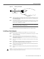
Step 5
Remove the screw that secures the port adapter (or blank port adapter).
Step 6
With the screw removed, grasp the handle on the front of the port adapter (or blank port
adapter) and carefully pull it out of its slot, away from the edge connector at the rear of
the slot. (See Figure 3-4.)
PA-T3 Serial Port Adapter Installation and Configuration
Installing a Port Adapter
Pulling a Port Adapter Out of a Slot—Partial Port Adapter View
H3149
Figure 3-4
Step 7
If you removed a port adapter, place it in an antistatic container for safe storage or
shipment back to the factory. If you removed a blank port adapter, no special handling is
required; however, store the blank port adapter for potential future use.
This completes the procedure for removing a new port adapter on a VIP2.
Installing a Port Adapter
Following is the standard procedure for installing a port adapter on the VIP2.
Remove the new port adapter from its antistatic container and position it at the opening
of the slot.
Step 2
Carefully align the port adapter carrier between the upper and the lower edges of the port
adapter slot, as shown in Figure 3-5.
Aligning a Port Adapter in a Port Adapter Slot
H3150
Figure 3-5
Step 1
Carrier
Upper edge
Lower edge
VIP2 and the PA-T3 Port Adapter 3-5
Installing a Port Adapter
Caution To prevent jamming the carrier between the upper and the lower edges of the port adapter
slot and to ensure that the edge connector at the rear of the port adapter mates with the connector at
the rear of the port adapter slot, make certain that the leading edges of the carrier are between the
upper and the lower slot edges, as shown in the cutaway in Figure 3-5.
Caution To ensure a positive ground attachment between the port adapter carrier and the VIP2
motherboard and port adapter slot, and to ensure that the connectors at the rear of the port adapter
and slot mate properly, position the carrier between the upper and the lower slot edges, as shown in
Figure 3-5.
Step 3
Port Adapter Installed in a Port Adapter Slot—Partial Port Adapter View
H3152
Figure 3-6
Carefully slide the new port adapter into the port adapter slot until the connector on the
port adapter is completely seated in the connector on the motherboard. (See Figure 3-6.)
3-6
Step 4
Replace the screw in the rear of the port adapter slot. (See Figure 3-3 for its location.) Do
not overtighten this screw.
Step 5
Reinstall the VIP2 in the system. (Follow the steps in the section “Installing a VIP2” in
the configuration note Second-Generation Versatile Interface Processor [VIP2]
Installation and Configuration, which shipped with your VIP2.)
Step 6
If the interface cables have been disconnected, reconnect the interface cables to the port
adapters.
PA-T3 Serial Port Adapter Installation and Configuration
Installing a Port Adapter
This completes the procedure for installing a port adapter on a VIP2. Proceed to Chapter 8,
“Configuring the PA-T3 Interfaces,” for information on how to configure your port adapter
interfaces.
VIP2 and the PA-T3 Port Adapter 3-7
Installing a Port Adapter
3-8
PA-T3 Serial Port Adapter Installation and Configuration
C H A P TER
4
Catalyst RSM/VIP2 and the PA-T3
Port Adapter
This chapter provides information on the PA-T3 serial port adapter and its use on the
Catalyst RSM/VIP2 in the Catalyst 5000 series switches. This chapter contains the following
sections:
•
•
•
Overview, page 4-1
Removing a Port Adapter, page 4-3
Installing a Port Adapter, page 4-4
Overview
The PA-T3 serial port adapter is used on the Catalyst RSM/VIP2 in the Catalyst 5000 series switches
and can be installed in either port adapter slot 0 or slot 1 on the Catalyst RSM/VIP2 motherboard.
Note You can have up to three T3 serial interfaces on a Catalyst RSM/VIP2 motherboard. Cisco
recommends a configuration of one PA-T3 serial port adapter (with one T3 serial interface) and one
PA-2T3 serial port adapter (with two serial interfaces) for a total of three T3 serial interfaces per
Catalyst RSM/VIP2.
Figure 4-1 shows two one-port PA-T3 serial port adapters installed in port adapter slot 0 and slot 1
on a Catalyst RSM/VIP2-15 or Catalyst RSM/VIP2-40.
Catalyst RSM/VIP2 and the PA-T3 Port Adapter 4-1
Overview
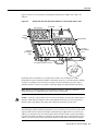
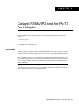
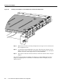
Figure 4-1
Catalyst RSM/VIP2-15 or Catalyst RSM/VIP2-40 with One-Port PA-T3 Serial
Port Adapters in Port Adapter Slots 0 and 1
Backplane
bus connector
Standoff
mounting
hole
Ribbon cables
Standoff
mounting
holes
Standoff
mounting
holes
PA-T3 in port
adapter slot 0
PA-T3 in port
adapter slot 1
LK
VR
C
R
C
R
TR
F
R
FE
L
DS3 SERIAL
D
AIS
F
O
O
LL
LK
LE
R
VR
AB
EN
XM
C
R
C
R
TR
XM
AIS
F
O
O
LL
F
R
FE
L
DS3 SERIAL
R
25704
D
LE
AB
EN
Port adapter
handles not
shown
Note Port adapters have a handle attached, but this handle is not shown to allow a full view of detail
on each port adapter’s faceplate.
Depending on the circumstances, you might need to install a new port adapter on a
Catalyst RSM/VIP2 motherboard or replace a failed port adapter in the field. In either case, you need
a number 1 Phillips screwdriver, an antistatic mat on which you can place the removed interface
processor, and an antistatic container in which you can place a failed port adapter for shipment back
to the factory.
Caution To prevent system problems, do not remove port adapters from the Catalyst RSM/VIP2
motherboard or attempt to install other port adapters on the Catalyst RSM/VIP2 motherboard while
the system is operating. To install or replace port adapters, first remove the Catalyst RSM/VIP2 from
the chassis.
Note Each port adapter circuit board is mounted to a metal carrier and is sensitive to ESD damage.
The following procedures should be performed by a Cisco-certified service provider only. The
Catalyst RSM/VIP2 supports online insertion and removal (OIR), but individual port adapters do
not. To replace port adapters, you must first remove the Catalyst RSM/VIP2 from the chassis and
then install or replace port adapters as required. If a blank port adapter is installed on the Catalyst
RSM/VIP2 in which you want to install a new port adapter, you must first remove the Catalyst
RSM/VIP2 from the chassis and then remove the blank port adapter.
4-2
PA-T3 Serial Port Adapter Installation and Configuration
Removing a Port Adapter
When only one port adapter is installed on a Catalyst RSM/VIP2, you must use a blank port adapter
to fill the empty slot. This allows the Catalyst RSM/VIP2 and the Catalyst RSM/VIP2 chassis to
conform to electromagnetic interference (EMI) emissions requirements and encourages air to flow
through the chassis properly. If you plan to install a new port adapter, you must first remove the blank
port adapter.
Removing a Port Adapter
Following is the standard procedure for removing any type of port adapter on the
Catalyst RSM/VIP2:
Step 1
Attach an ESD-preventive wrist strap between you and an unfinished chassis surface.
Note If you want to install a new port adapter on a Catalyst RSM/VIP2 with a single port
adapter, you must first remove the blank port adapter from the port adapter slot in which
you want to install the new port adapter.
Step 2
For a new port adapter installation or a port adapter replacement, disconnect any interface
cables from the ports on the front of the port adapter, although this is not required. You
can remove the Catalyst RSM/VIP2 with cables attached; however, we do not recommend
it.
Step 3
To remove the Catalyst RSM/VIP2 from the chassis, follow the steps in the Route Switch
Module Catalyst VIP2-15 and VIP2-40 Installation and Configuration Note (Document
Number 78-4780-01) which shipped with your Catalyst RSM/VIP2. Place the removed
Catalyst RSM/VIP2 on an antistatic mat.
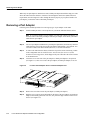
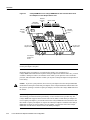
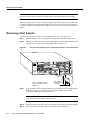
Step 4
Locate the screw at the rear of the port adapter (or blank port adapter) to be replaced.
(See Figure 4-2.) This screw secures the port adapter (or blank port adapter) to its slot.
Location of Port Adapter Screw—Partial Port Adapter View
H3148
Figure 4-2
Screw
Step 5
Remove the screw that secures the port adapter (or blank port adapter).
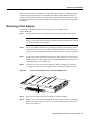
Step 6
With the screw removed, grasp the handle on the front of the port adapter (or blank port
adapter) and carefully pull it out of its slot, away from the edge connector at the rear of
the slot. (See Figure 4-3.)
Catalyst RSM/VIP2 and the PA-T3 Port Adapter 4-3
Installing a Port Adapter
Pulling a Port Adapter Out of a Slot—Partial Port Adapter View
H3149
Figure 4-3
Step 7
If you removed a port adapter, place it in an antistatic container for safe storage or
shipment back to the factory. If you removed a blank port adapter, no special handling is
required; however, store the blank port adapter for potential future use.
This completes the procedure for removing a new port adapter on a Catalyst RSM/VIP2.
Installing a Port Adapter
Following is the standard procedure for installing a port adapter on the Catalyst RSM/VIP2.
Step 1
Attach an ESD-preventive wrist strap between you and an unfinished chassis surface.
Note If you want to install a new port adapter on a Catalyst RSM/VIP2 with a single port
adapter, you must first remove the blank port adapter from the port adapter slot in which
you want to install the new port adapter.
4-4
Step 2
For a new port adapter installation or a port adapter replacement, disconnect any interface
cables from the ports on the front of the port adapter, although this is not required. You
can remove the Catalyst RSM/VIP2 with cables attached; however, we do not recommend
it.
Step 1
Remove the new port adapter from its antistatic container and position it at the opening
of the slot.
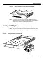
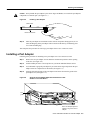
Step 2
Carefully align the port adapter carrier between the upper and the lower edges of the port
adapter slot, as shown in Figure 4-4.
PA-T3 Serial Port Adapter Installation and Configuration
Installing a Port Adapter
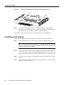
Aligning a Port Adapter in a Port Adapter Slot
H3150
Figure 4-4
Carrier
Upper edge
Lower edge
Caution To prevent jamming the carrier between the upper and the lower edges of the port adapter
slot and to ensure that the edge connector at the rear of the port adapter mates with the connector at
the rear of the port adapter slot, make certain that the leading edges of the carrier are between the
upper and the lower slot edges, as shown in the cutaway in Figure 4-4.
Caution To ensure a positive ground attachment between the port adapter carrier and the Catalyst
RSM/VIP2 motherboard and port adapter slot, and to ensure that the connectors at the rear of the
port adapter and slot mate properly, position the carrier between the upper and the lower slot edges,
as shown in Figure 4-4.
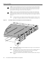
Step 3
Carefully slide the new port adapter into the port adapter slot until the connector on the
port adapter is completely seated in the connector on the motherboard. (See Figure 4-5.)
Catalyst RSM/VIP2 and the PA-T3 Port Adapter 4-5
Installing a Port Adapter
Installing a Port Adapter in a Port Adapter Slot—Partial Port Adapter View
H3152
Figure 4-5
Step 4
Replace the screw in the rear of the port adapter slot. (See Figure 4-2 for its location.) Do
not overtighten this screw.
Step 5
To reinstall the Catalyst RSM/VIP2 in the system, follow the steps in the Route Switch
Module Catalyst VIP2-15 and VIP2-40 Installation and Configuration Note (Document
Number 78-4780-01) which shipped with your Catalyst RSM/VIP2 .
Step 6
If the interface cables have been disconnected, reconnect the interface cables to the port
adapters.
This completes the procedure for installing a port adapter on a Catalyst RSM/VIP2. Proceed to
Chapter 8, “Configuring the PA-T3 Interfaces,” for information on how to configure your port
adapter interfaces.
4-6
PA-T3 Serial Port Adapter Installation and Configuration
C H A P TER
5
Cisco 7200 Series and the
PA-T3 Port Adapter
This chapter provides information on the PA-T3 port adapter and its use in Cisco 7200 series routers.
This chapter contains the following sections:
•
•
•
Overview, page 5-1
Removing a Port Adapter, page 5-2
Installing a Port Adapter, page 5-3
Overview
The PA-T3 serial port adapter can be installed in any available port adapter slot in Cisco 7200 series
routers (which consist of the two-slot Cisco 7202, four-slot Cisco 7204 and Cisco 7204VXR, and
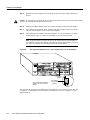
six-slot Cisco 7206 and Cisco 7206VXR). Figure 5-1 shows a one-port PA-T3 serial port adapter
installed in port adapter slot 3 of a Cisco 7206.
Figure 5-1
Cisco 7206 with a PA-T3 Serial Port Adapter in Port Adapter Slot 3
3
2
1
5
0
6
TOKEN RING
4
K
LIN
MII
0
1
0
TX
2
RX
4
TX
RX
3
TX
RX
2
TX
RX
TX
EN
CD
LB
RC
RD
TC
TD
CD
LB
RC
RD
ETHERNET-10BFL
RX
AIS
OO
F
LL
TC
TD
CD
LB
RC
RD
TC
TD
CD
LB
RC
RD
TC
TD
LE
AB
EN
LK
RF
RL
FE
TR
XM
VR
RC
D
LE
RC
AB
3
EN
EN
FAST SERIAL
0
SL
O
T
T
EC
EJ
IA
C
M
PC
EN
AB
LE
D
II
M
FE
II
M N
E
J-4
R EN
5
0
SL
O
T
1
FAST ETHERNET INPUT/OUTPUT CONTROLLER
5
J-4
R
5
R
PW
J-4 K
O K
LIN 1 O
R
H10042
1
PA-T3
port
adapter
RJ4
5
D
FAST ETHERNET
1DS3 SERIAL
Depending on your circumstances, you might need to install a new port adapter in a Cisco 7200
series router or replace a failed port adapter in the field. In either case, no tools are necessary; all port
adapters available for the Cisco 7200 series connect directly to the router midplane and are locked
into position by a port adapter lever. When removing and replacing a port adapter, you need an
antistatic mat onto which you can place a removed port adapter and an antistatic container into which
you can place a failed port adapter for shipment back to the factory.
Cisco 7200 Series and the PA-T3 Port Adapter 5-1
Removing a Port Adapter
Note The Cisco 7200 series routers support online insertion and removal; therefore, you do not
have to power down the Cisco 7200 series routers when removing and replacing a port adapter.
When a port adapter slot is not in use, a blank port adapter must fill the empty slot to allow the router
to conform to EMI emissions requirements and to allow proper airflow across the port adapters. If
you plan to install a new port adapter in a slot that is not in use, you must first remove a blank port
adapter.
Removing a Port Adapter
Following is the procedure for removing a port adapter from a Cisco 7200 series router:
Step 1
Attach an ESD-preventive wrist strap between you and an unfinished chassis surface.
Step 2
Place the port adapter lever for the desired port adapter slot in the unlocked position. The
port adapter lever remains in the unlocked position. (See Figure 5-2.)
Figure 5-2
Placing the Port Adapter Lever in the Unlocked Position—Cisco 7206 Shown
3
2
1
5
0
6
TOKEN RING
FAST ETHERNET
4
K
RJ4
0
LIN
MII
5
D
LE
AB
EN
3
2
3
LINK
1
0
2
1
0
EN
3
AB
LE
D
ETHERNET 10BT
2
CD
LB
RC
RD
TC
TD
CD
LB
RC
RD
TC
TD
CD
LB
RC
RD
TC
TD
CD
LB
RC
RD
TC
ET
ES
II
0
D
LE
AB
5
O PW
K R
R
E J4
N 5
1O
R
L J4
IN
K
M
E II
N
T
0
T
O
SL
EC
EJ
PC
M
C
IA
EN
H6596
C
45
R
J-
FAST ETHERNET INPUT/OUTPUT CONTROLLER
PU
R
M
FE
SL
O
T
1
1
TD
EN
FAST SERIAL
Port adapter
handle
Note: This adapter removal
applies to any port or service
adapter.
Step 3
Port adapter
lever (unlocked
position)
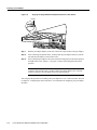
Grasp the handle on the port adapter and pull the port adapter from the midplane, about
halfway out of its slot. If you are removing a blank port adapter, pull the blank
port adapter completely out of the chassis slot.
Note As you disengage the port adapter from the router midplane, OIR administratively
shuts down all active interfaces on the port adapter.
5-2
Step 4
With the port adapter halfway out of the slot, disconnect all cables from the port adapter.
Step 5
After disconnecting the cables, pull the port adapter from its chassis slot.
PA-T3 Serial Port Adapter Installation and Configuration
Installing a Port Adapter
Caution Always handle the port adapter by the carrier edges and handle; never touch the port adapter’s
components or connector pins. (See Figure 5-3.)
Figure 5-3
Handling a Port Adapter
Metal carrier
H6420
Printed circuit board
Step 6
Place the port adapter on an antistatic surface with its components facing upward, or in a
static shielding bag. If the port adapter will be returned to the factory, immediately place
it in a static shielding bag.
This completes the procedure for removing a port adapter from a Cisco 7200 series router.
Installing a Port Adapter
Following is the procedure for installing a new port adapter in a Cisco 7200 series router:
Step 1
Remove the new port adapter from its antistatic container and position it at the opening
of the slot. (See Figure 5-4.)
Step 2
Attach an ESD-preventive wrist strap between you and an unfinished chassis surface.
Step 3
Use both hands to grasp the port adapter by its metal carrier edges and position the port
adapter so that its components are downward. (See Figure 5-3.)
Step 4
Align the left and right edge of the port adapter metal carrier between the guides in the
port adapter slot. (See Figure 5-4.)
Aligning the Port Adapter Metal Carrier Between the Slot
Guides—Cisco 7206 Shown
2
1
0
6
3
TOKEN RING
5
FAST ETHERNET
4
5
RJ4
MII
2
0
LIN
K
D
AB
LE
EN
3
3
2
2
1
0
LINK
1
0
3
EN
AB
LE
D
ETHERNET 10BT
ES
ET
II
45
R
J-
C
PU
R
M
FE
AB
LE
D
SL
O
T
1
1
FAST ETHERNET INPUT/OUTPUT CONTROLLER
5
O PW
K R
1O
M
E II
N
R
E J4
N 5
R
L J4
IN
K
T
0
T
EC
O
SL
EJ
PC
M
C
IA
EN
Slot
guide
H6597
Figure 5-4
Note: This adapter alignment
applies to any port or service
adapter.
Cisco 7200 Series and the PA-T3 Port Adapter 5-3
Installing a Port Adapter
Step 5
With the metal carrier aligned in the slot guides, gently slide the port adapter halfway into
the slot.
Caution Do not slide the port adapter all the way into the slot until you have connected all required cables.
Trying to do so disrupts normal operation of the router.
Step 6
With the port adapter halfway in the slot, connect all required cables to the port adapter.
Step 7
After connecting all required cables, carefully slide the port adapter all the way into the
slot until the port adapter is seated in the router midplane.
Step 8
After seating the port adapter in the router midplane, move the port adapter lever to the
locked position. Figure 5-5 shows the port adapter lever in the locked position.
Note If the port adapter lever does not move to the locked position, the port adapter is
not completely seated in the midplane. Carefully pull the port adapter halfway out of the
slot, reinsert it, and move the port adapter lever to the locked position.
Figure 5-5
Placing the Port Adapter Lever in the Locked Position—Cisco 7206 Shown
3
2
1
5
0
6
TOKEN RING
FAST ETHERNET
4
K
RJ4
0
LIN
MII
5
D
LE
AB
EN
3
2
3
LINK
1
0
2
1
0
EN
3
AB
LE
D
ETHERNET 10BT
2
CD
LB
RC
RD
TC
TD
CD
LB
RC
RD
TC
TD
CD
LB
RC
RD
TC
TD
CD
LB
RC
RD
TC
ET
ES
II
0
D
LE
AB
5
O PW
K R
R
E J4
N 5
1O
R
L J4
IN
K
M
E II
N
T
0
T
EC
O
EJ
SL
PC
M
C
IA
EN
H6747
C
45
R
J-
FAST ETHERNET INPUT/OUTPUT CONTROLLER
PU
R
M
FE
SL
O
T
1
1
TD
EN
FAST SERIAL
Port adapter
handle
Note: This adapter installation
applies to any port or service
adapter.
Port adapter
lever (locked
position)
This completes the procedure for installing a new port adapter in a Cisco 7200 series router. Proceed
to Chapter 8, “Configuring the PA-T3 Interfaces,” for information on how to configure your port
adapter interfaces.
5-4
PA-T3 Serial Port Adapter Installation and Configuration
C H A P TER
6
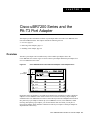
Cisco uBR7200 Series and the
PA-T3 Port Adapter
This chapter provides information on the PA-T3 port adapter and its use in the Cisco uBR7200 series
universal broadband routers. This chapter includes the following sections:
•
•
•
Overview, page 6-1
Removing a Port Adapter, page 6-2
Installing a Port Adapter, page 6-4
Overview
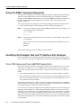
The PA-T3 port adapter can be installed in any of the available port adapter slots in the
Cisco uBR7200 series routers. Figure 6-1 shows a PA-T3 port adapter installed in port adapter slot 2
of a Cisco uBR7200 series router.
C
LK
FE
R
R F
L
TR
15261
AIS
O
O
F
LL
XM
VR
C
R
DS3 SERIAL
R
D
LE
AB
PA-T3
port adapter
Cisco uBR7200 Series with a PA-T3 Port Adapter in Port Adapter Slot 2
EN
Figure 6-1
Depending on the circumstances, you might need to install a new port adapter or replace a failed port
adapter in a Cisco uBR7200 series router. In either case no tools are necessary; all port adapters
available for the Cisco uBR7200 series routers connect directly to the router midplane and are locked
into position by a port adapter retention clip (Cisco uBR7246) or lever (Cisco uBR7223). When
removing and replacing a port adapter, you need an antistatic mat onto which you can place a
removed port adapter and an antistatic container into which you can place a failed port adapter for
shipment back to the factory.
Cisco uBR7200 Series and the PA-T3 Port Adapter 6-1
Removing a Port Adapter
Note Cisco uBR7200 series routers support OIR; therefore, you do not have to power down the
router when removing and replacing a PA-T3 port adapter.
When a port adapter slot is not in use, blank port adapters must fill empty slots to allow the router to
conform to EMI emissions requirements and to allow proper airflow across the port adapters. If you
plan to install a new port adapter in a slot that is not in use, you must first remove the blank port
adapter.
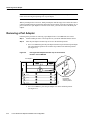
Removing a Port Adapter
Following is the procedure for removing a port adapter from a Cisco uBR7200 series router:
Step 1
Attach an ESD-preventive wrist strap between you and an unfinished chassis surface.
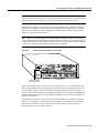
Step 2
Place the port adapter retention clips or levers in the unlocked position:
•
Figure 6-2
For a Cisco uBR7246, place the port adapter retention clip for the desired port adapter
slot in the unlocked position. The retention clip remains in the unlocked position.
(See Figure 6-2.)
Placing the Port Adapter Retention Clip in the Unlocked
Position—Cisco uBR7246
H11518
Port adapters
•
6-2
Port adapter
retention clip in
unlocked position
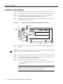
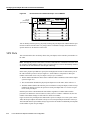
For a Cisco uBR7223, place the port adapter lever in the unlocked position.
(See Figure 6-3.)
PA-T3 Serial Port Adapter Installation and Configuration
Removing a Port Adapter
Figure 6-3
Placing the Port Adapter Lever in the Unlocked Position—Cisco uBR7223
Port adapter
lever in unlocked
position
16217
Port adapters
Grasp the handle on the port adapter and pull the port adapter from the router midplane,
about halfway out of its slot. If you are removing a blank port adapter, pull the blank
port adapter completely out of the chassis slot.
Step 3
Note As you disengage the port adapter from the midplane, OIR administratively shuts
down all active interfaces on the port adapter.
Step 4
With the port adapter halfway out of the slot, disconnect all cables from the port adapter.
Step 5
After disconnecting the cables, pull the port adapter from its chassis slot.
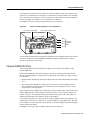
Caution Always handle the port adapter by the carrier edges and handle; never touch the port
adapter’s components or connector pins. (See Figure 6-4.)
Figure 6-4
Handling a Port Adapter
Metal carrier
H6420
Printed circuit board
Step 6
Place the port adapter on an antistatic surface with its components facing upward, or in a
static shielding bag. If the port adapter will be returned to the factory, immediately place
it in a static shielding bag.
This completes the procedure for removing a port adapter from a Cisco uBR7200 series router.
Cisco uBR7200 Series and the PA-T3 Port Adapter 6-3
Installing a Port Adapter
Installing a Port Adapter
Following is the procedure for installing a new port adapter in a Cisco uBR7200 series router:
Step 1
Attach an ESD-preventive wrist strap between you and an unfinished chassis surface.
Step 2
Use both hands to grasp the port adapter by its metal carrier edges and position the
port adapter so that its components are downward. (See Figure 6-4.)
Step 3
Align the left and the right edge of the port adapter metal carrier between the guides in
the port adapter slot. (See Figure 6-5.)
Figure 6-5
Aligning the Port Adapter Metal Carrier Between the Slot Guides
Metal carrier
PC board
Step 4
H11519
Inside
slot guide
With the metal carrier aligned in the slot guides, gently slide the port adapter halfway into
the slot.
Caution Do not slide the port adapter all the way into the slot until you have connected all required
cables. Trying to do so disrupts normal operation of the router.
Step 5
With the port adapter halfway in the slot, connect all required cables to the port adapter.
Step 6
After connecting the cables, carefully slide the port adapter all the way into the slot until
the port adapter is seated in the router midplane.
Step 7
Place the port adapter retention clips or levers in the locked position:
•
For a Cisco uBR7246, slide the port adapter retention clip up to the locked position.
(See Figure 6-6).
Note If the retention clip does not slide up to the locked position, the port adapter is not
completely seated in the midplane. Carefully pull the port adapter halfway out of the slot,
reinsert it, and slide the retention clip up to the locked position.
6-4
PA-T3 Serial Port Adapter Installation and Configuration
Installing a Port Adapter
Figure 6-6
Placing the Port Adapter Retention Clip in the Locked
Position—Cisco uBR7246 Shown
H11517
Port adapters
•
Figure 6-7
Port adapter
retention clip in
locked position
For a Cisco uBR7223, place the port adapter lever in the locked position.
(See Figure 6-7.)
Placing the Port Adapter Lever in the Locked
Position—Cisco uBR7223 Shown
Port adapter
lever in locked
position
16177
Port adapters
Note If the port adapter lever does not move to the locked position, the port adapter is
not completely seated in the midplane. Carefully pull the port adapter halfway out of the
slot, reinsert it, and move the port adapter lever to the locked position.
This completes the procedure for installing a port adapter in a Cisco uBR7200 series router. Proceed
to Chapter 8, “Configuring the PA-T3 Interfaces,” for information on how to configure your port
adapter interfaces.
Cisco uBR7200 Series and the PA-T3 Port Adapter 6-5
Installing a Port Adapter
6-6
PA-T3 Serial Port Adapter Installation and Configuration
C H A P TER
8
Configuring the PA-T3 Interfaces
To continue your PA-T3 port adapter installation, you must configure the PA-T3 interfaces. The
instructions that follow apply to all supported platforms. Minor differences between the platforms
are noted. This chapter contains the following sections:
•
•
•
•
•
•
•
•
Using the EXEC Command Interpreter, page 8-2
Identifying Port Adapter Slot and T3 Interface Port Numbers, page 8-2
Shutting Down an Interface, page 8-7
Performing a Basic Configuration, page 8-10
Configuration Example, page 8-11
Customizing the PA-T3 Serial Port Adapter, page 8-12
Configuring Cyclic Redundancy Checks, page 8-13
Checking the Configuration, page 8-14
If you installed a new PA-T3 port adapter or if you want to change the configuration of an existing
interface, you must enter configuration mode using the configure command. If you replaced a PA-T3
port adapter that was previously configured, the system recognizes the new PA-T3 port adapter
interfaces and brings each of them up in their existing configuration.
After you verify that the new PA-T3 port adapter is installed correctly (the enabled LED goes on),
use the privileged-level configure command to configure the new interfaces. Be prepared with the
information you need, such as the following:
•
•
•
•
Protocols you plan to route on each new interface
IP addresses if you will configure the interfaces for IP routing
Use of bridging on the new interfaces
Timing source for each new interface and clock speeds for external timing
For a summary of the configuration options available and instructions for configuring interfaces on
the PA-T3 port adapter, refer to the appropriate configuration publications listed in the “Related
Documentation” section on page vi.
Configuration commands are executed from the privileged level of the EXEC command interpreter,
which usually requires password access. Contact your system administrator, if necessary, to obtain
access. (See the “Using the EXEC Command Interpreter” section on page 8-2 for an explanation of
the privileged level of the EXEC.)
Configuring the PA-T3 Interfaces 8-1
Using the EXEC Command Interpreter
Using the EXEC Command Interpreter
You modify the configuration of your router through the software command interpreter called the
EXEC (also called enable mode). You must enter the privileged level of the EXEC command
interpreter with the enable command before you can use the configure command to configure a new
interface or change the existing configuration of an interface. The system prompts you for a
password if one is set.
The system prompt for the privileged level ends with a pound sign (#) instead of an angle bracket
(>). At the console terminal, use the following procedure to enter the privileged level:
Step 1
At the user-level EXEC prompt, enter the enable command. The EXEC prompts you for
a privileged-level password as follows:
Router> enable
Password:
Step 2
Enter the password (the password is case-sensitive). For security purposes, the password
is not displayed.
When you enter the correct password, the system displays the privileged-level system
prompt (#):
Router#
Proceed to the following sections to configure the new interfaces.
Identifying Port Adapter Slot and T3 Interface Port Numbers
This section describes how to identify port adapter slot and PA-T3 interface port numbers for the
Cisco 7200 series routers, the Cisco uBR7200 series routers, the VIP2, and the Catalyst RSM/VIP2.
Cisco 7200 Series and Cisco uBR7200 Series Ports
Physical port addresses specify the actual physical location of each interface port on a Cisco 7200
series router (see Figure 8-1) or a Cisco uBR7200 series router (see Figure 8-2). This address is
composed of a two-part number in the format port adapter slot number/interface port number, as
follows:
•
•
The first number identifies the chassis slot in which the PA-T3 serial port adapter is installed.
The second number identifies the interface port on each PA-T3 serial port adapter; the interface
port is always numbered as interface 0 for the one-port PA-T3 serial port adapter and 0 or 1 for
a two-port PA-2T3 serial port adapter.
Interface ports maintain the same address regardless of whether other port adapters are installed or
removed from the slot. However, when you move a port adapter to a different slot, the first number
in the address changes to reflect the new chassis slot number.
In Cisco 7200 series routers, port adapter slots are numbered from the lower left to the upper right,
beginning with port adapter slot 1 and continuing through port adapter slot 2 for the Cisco 7202,
slot 4 for the Cisco 7204 and Cisco 7204VXR, and slot 6 for the Cisco 7206 and Cisco 7206VXR.
Port adapter slot 0 is reserved for the optional Fast Ethernet port on the I/O controller—if present.
Figure 8-1 shows the port adapter slots and interface ports of a Cisco 7206. The individual interface
port numbers always begin with 0. The number of additional ports depends on the number of ports
on a port adapter.
8-2
PA-T3 Serial Port Adapter Installation and Configuration
Cisco 7200 Series and Cisco uBR7200 Series Ports
Note The I/O controller is available with or without a Fast Ethernet port. You can install both I/O
controller types in all Cisco 7200 series routers; however, when you install an I/O controller with a
Fast Ethernet port in a Cisco 7202, the system software automatically disables the port.
For example, the serial port on a one-port PA-T3 serial port adapter in port adapter slot 3 has the
address 3/0. (See Figure 8-1.) If the PA-T3 serial port adapter is in port adapter slot 1, this same
interface port is numbered 1/0. The serial ports on a two-port PA-2T3 serial port adapter in port
adapter slot 3 has the address 3/0 and 3/1.
Note The PA-T3 serial port adapter is considered a high-bandwidth port adapter; you must observe
specific configuration guidelines. Refer to the publication Cisco 7200 Series Port Adapter Hardware
Configuration Guidelines, which shipped with your Cisco 7200 series chassis and is also available
on the Cisco Connection Documentation, Enterprise Series CD-ROM.
Figure 8-1
Serial Port Number Example—Cisco 7206
3
2
1
5
0
6
TOKEN RING
4
K
RJ4
LIN
MII
0
1
0
TX
2
RX
4
TX
RX
3
TX
RX
0
SL
O
T
T
EC
EJ
IA
C
M
PC
EN
AB
LE
D
II
M
II
M N
E
5
J-4
R EN
R
5
PW
J-4 K
O K
LIN 1 O
R
0
FE
SL
O
T
1
FAST ETHERNET INPUT/OUTPUT CONTROLLER
5
J-4
R
H10043
1
2
TX
RX
TX
EN
CD
LB
RC
RD
TC
TD
CD
LB
RC
RD
ETHERNET-10BFL
RX
AIS
OO
F
LL
TC
TD
CD
LB
RC
RD
TC
TD
CD
LB
RC
RD
TC
LE
AB
EN
LK
RF
RL
FE
TR
XM
RC
RC
D
VR
LE
AB
3
EN
EN
FAST SERIAL
TD
5
D
FAST ETHERNET
1DS3 SERIAL
PA-T3 port adapter
(port number 3/0)
Figure 8-2 shows the interface ports of a PA-T3 port adapter in slot 2 of a Cisco uBR7200 series
router. The port adapter slots are numbered slot 1 and slot 2 for the Cisco uBR7246 and slot 1 for
the Cisco uBR7223 (slot 0 is always reserved for the Fast Ethernet port on the I/O controller—if
present). The individual interface port numbers always begin with 0. The number of additional ports
depends on the number of ports on a port adapter. Port adapters can occupy any port adapter slot;
there are no restrictions.
For example, the serial port on a one-port PA-T3 serial port adapter in port adapter slot 1 has the
address 1/0. (See Figure 8-2.) If the PA-T3 serial port adapter is in port adapter slot 2, this same
interface port is numbered 2/0. The serial ports on a two-port PA-2T3 serial port adapter in
port adapter slot 2 have the address 2/0 and 2/1.
Configuring the PA-T3 Interfaces 8-3
Identifying Port Adapter Slot and T3 Interface Port Numbers
C
LK
FE
R
R F
L
R
TR
VR
C
15262
AIS
O
O
F
LL
R
DS3 SERIAL
XM
AB
LE
D
PA-T3
port adapter
(port number 1/0)
PA-T3 Interface Port Address Example—Cisco uBR7246
EN
Figure 8-2
You can identify interface ports by physically checking the port adapter slot number/interface port
location on the back of the router or by using software commands to display information about a
specific interface or all interfaces in the router.
VIP2 Ports
This section describes how to identify chassis slot, port adapter, and T3 interface port numbers on
the VIP2.
Note Although the processor slots in the 7-slot Cisco 7000 and Cisco 7507 and 13-slot Cisco 7513
are vertically oriented and those in the 5-slot Cisco 7010 and Cisco 7505 are horizontally oriented,
all models use the same method for slot and port numbering.
In the router, physical port addresses specify the actual physical location of each interface port on
the router interface processor end. (See Figure 8-3.) Each address is composed of a three-part
number in the format chassis slot/port adapter/interface port, as follows:
•
The first number identifies the chassis slot in which the VIP2 is installed (as shown in the sample
system in Figure 8-3).
•
•
The second number identifies the physical port adapter slot on the VIP2, and is either 0 or 1.
The third number identifies the interface port on each PA-T3 serial port adapter, which is always
numbered as interface 0 for the one-port PA-T3 serial port adapter and 0 or 1 for the two-port
PA-T3 serial port adapter.
Interface ports on the VIP2 maintain the same address regardless of whether other interface
processors are installed or removed. However, when you move a VIP2 to a different slot, the first
number in the address changes to reflect the new chassis slot number.
Figure 8-3 shows the port adapter slots and interface ports of a sample Cisco 7505 system. On the
VIP2, the first port adapter slot number is always 0. The second port adapter slot number is always 1.
The individual interface port numbers always begin with 0. The number of additional ports depends
on the number of ports on a port adapter.
8-4
PA-T3 Serial Port Adapter Installation and Configuration
Catalyst RSM/VIP2 Ports
For example, the serial port on a one-port PA-T3 serial port adapter in the first port adapter slot in
chassis slot 3, is numbered 3/0/0. (See Figure 8-3.) If the PA-T3 serial port adapter is in port adapter
slot 1, this same port is numbered 3/1/0. The serial ports on a two-port PA-T3 serial port adapter in
the first port adapter slot in chassis slot 3 are numbered 3/0/0 and 3/0/1.
Port adapters can occupy either port adapter slot; there are no restrictions.
Serial Port Number Example—Cisco 7505 Shown
CP
U
ROUTE SWITCH PROCESSOR
CO
NS
OL
E
HA
LT
PA-T3 (port numbers 3/1/0)
SL SLO
OT T
0 1
NO
RM
AL
EJ
EC
T
PA-T3 (port number 3/0/0)
RE
SE
T
Figure 8-3
RF
RL
FE
TR
LL
AIS
OO
F
F
LL
OO
AIS
Slot 3
XM
VR
RC
D
LE
AB
RC
EN
LK
RF
RL
FE
XM
TR
RC
D
LE
VR
RC
AB
EN
LK
1DS3 SERIAL
1DS3 SERIAL
Slot 2
Slot 1
Interface
processor
slots
H10044
Slot 0
You can identify interface ports by physically checking the slot/port-adapter/interface port location
on the back of the router or by using show commands to display information about a specific
interface or all interfaces in the router.
Catalyst RSM/VIP2 Ports
This section describes how to identify the port adapter and T3 interface port numbers on the
Catalyst RSM/VIP2.
In the Catalyst RSM/VIP2, physical port addresses specify the actual physical location of each
interface port. Each address is composed of a two-part number in the format port adapter/interface
port, as follows:
•
The first number identifies the physical port adapter slot on the Catalyst RSM/VIP2, and is either
0 or 1.
•
The second number identifies the interface port on each PA-T3 serial port adapter, which is
always numbered as interface 0 for the one-port PA-T3 serial port adapter and 0 or 1 for the
two-port PA-T3 serial port adapter.
Figure 8-4 shows the port adapter slots and interface ports of a sample Catalyst 5509 switch. On the
Catalyst RSM/VIP2, the first port adapter slot number is always 0. The second port adapter slot
number is always 1. The individual interface port numbers always begin with 0. The number of
additional ports depends on the number of ports on a port adapter.
For example, the serial port on a one-port PA-T3 serial port adapter in the first port adapter slot is
numbered 0/0. (See Figure 8-4.) If the PA-T3 serial port adapter is in port adapter slot 1, this same
port is numbered 1/0. The serial ports on a two-port PA-T3 serial port adapter in the first port adapter
slot are numbered 0/0 and 0/1.
Port adapters can occupy either port adapter slot; there are no restrictions.
Configuring the PA-T3 Interfaces 8-5
Identifying Port Adapter Slot and T3 Interface Port Numbers
Figure 8-4
PA-T3 Serial Port Adapter in the Catalyst 5509
You can identify interface ports by physically checking the port-adapter/interface port location by
using show commands to display information about a specific interface or all interfaces in the router.
Cisco 7100 Series Ports
In the Cisco 7100 series routers, the slot number is the location in the chassis where the interface
resides and the port number is the physical port. Interfaces in the Cisco IOS software are identified
by a type, slot number, and port number. For example, serial 3/1 indicates port 1 on the serial
port adapter in slot 3.
Slots in the Cisco 7120 series routers are numbered as shown in Figure 8-5. The fixed LAN interface
is slot 0, the fixed WAN interface is slot 1, and the modular port adapter interface is slot 3. In the
Cisco 7120 series routers, slots 2 and 4 are not used. Slot 5 is the service module.
Figure 8-5
Port Adapter Slot Numbering—Cisco 7120 Series
Slot 5
Slot 3
SLOT 0
SLOT 1
PWR
ACT ACT
0
FE 0 / 0
I
E3
EN
TX
FE
0/1
CONS
AUX
SYS
RDY
RX
RX
2
CEL CAR ALM
7120 - AE3
Slot 1
8-6
LNK LNK
0
1
Slot 0
PA-T3 Serial Port Adapter Installation and Configuration
18498
5
Shutting Down an Interface
Slots in the Cisco 7140 series routers are numbered as shown in Figure 8-6. The fixed LAN interface
is slot 0, the fixed WAN interfaces are slots 1 and 2, and the modular port adapter interface is slot 4.
Slot 3 is not used. Slot 5 is the service adapter.
Figure 8-6
Port Adapter Slot Numbering—Cisco 7140 Series
Slot 5
Slot 4
AC OK
DC OK
OTF
RESET
SLOT 0
BOOT
ERROR
PWR
EN
5
0
FE 0 / 0
I
SLOT 1
ACT ACT
RX
EN
RX
155 - MM
TX
EN
CEL CAR ALM
FE 0 / 1
RX
LNK LNK
0
1
RX
155 - MM
CEL CAR ALM
Slot 1
AUX
CONS
AC OK
SYS
RDY
DC OK
OTF
TX
2
7140 - 2MM3
18499
SM-EC-DS
Slot 0 Slot 2
Shutting Down an Interface
Before you remove an interface that you will not replace, replace a compact serial cable, or replace
port adapters, use the shutdown command to shut down (disable) the interfaces to prevent anomalies
when you reinstall the new or reconfigured interface processor. When you shut down an interface, it
is designated administratively down in the show command displays.
Follow these steps to shut down an interface:
Step 1
Enter the privileged level of the EXEC command interpreter (also called enable mode).
(See the “Using the EXEC Command Interpreter” section on page 8-2 for instructions.)
Step 2
At the privileged-level prompt, enter configuration mode and specify that the console
terminal is the source of the configuration subcommands, as follows:
Router# configure terminal
Enter configuration commands, one per line.
Router(config)#
Step 3
Table 8-1
End with Crtl-Z.
Specify the slot/port address of the first interface that you want shut down by entering the
subcommand interface as described in .
Interface Subcommand Syntax
Platform
Command
Example
Cisco 7200 series or Cisco uBR7200
interface, followed by the type
(serial) and slot/port (port adapter
slot number/0)
Router(config)# interface serial 1/0
VIP2
interface, followed by the type
(serial) and slot/port (interface
processor slot number/0)
Router(config)# interface serial
1/1/0
Catalyst RSM/VIP2
interface, followed by the type
(serial) and port adapter slot
number/interface port number (port
adapter slot number/0)
Router(config)# interface serial 0/0
Configuring the PA-T3 Interfaces 8-7
Shutting Down an Interface
Table 8-1
Interface Subcommand Syntax (continued)
Platform
Command
Example
Cisco 7120
interface, followed by the type
(serial) and port adapter
number/interface port number
Router(config)# interface serial 3/0
Cisco 7140
interface, followed by the type
(serial) and port adapter
number/interface port number
Router(config)# interface serial 4/0
Step 4
Enter the shutdown command as follows:
Router(config-if)# shutdown
Step 5
To shut down additional interfaces, enter the slot/port address (or slot/port
address/interface port for a VIP2) of each additional interface followed by the shutdown
command. When you have entered all the interfaces to be shut down, press Ctrl-Z (hold
down the Control key while you press Z) or enter end to exit configuration mode and
return to the EXEC command interpreter prompt.
The example that follows is for the Cisco 7100 series, Cisco 7200 series, or
Cisco uBR7200 series routers:
Router(config-if)#
Router(config-if)#
Router(config-if)#
Router(config-if)#
Ctrl-Z
Router#
interface serial 1/0
shutdown
interface serial 1/1
shutdown
The example that follows is for a VIP2:
Router(config-if)#
Router(config-if)#
Router(config-if)#
Router(config-if)#
Ctrl-Z
Router#
interface serial 1/1/0
shutdown
interface serial 1/1/1
shutdown
The example that follows is for a Catalyst RSM/VIP2:
Router(config-if)#
Router(config-if)#
Router(config-if)#
Router(config-if)#
Ctrl-Z
Router#
Step 6
interface serial 1/0
shutdown
interface serial 1/1
shutdown
Write the new configuration to memory as follows:
Router# copy running-config startup-config
[OK]
Router#
The system displays an OK message when the configuration has been stored.
Step 7
8-8
Verify that new interfaces are now in the correct state (shutdown). To do so on the
Cisco 7100 series, Cisco 7200 series, or Cisco uBR7200 series routers, use the show
interfaces serial slot/port command to display the specific interface, or use the show
interfaces command, without variables, to display the status of all interfaces in the
system.
PA-T3 Serial Port Adapter Installation and Configuration
Shutting Down an Interface
The example that follows is for Cisco 7100 series, Cisco 7200 series, or Cisco uBR7200
series routers:
Router# show interfaces serial 1/0
Serial 1/0 is administratively down, line protocol is down
Hardware is M1T-T3 pa
[display text omitted]
To verify that new interfaces are now in the correct state (shutdown) on a VIP2, use the
show interfaces serial slot/port adapter/interface command to display the specific
interface, or use the show interfaces command, without variables, to display the status of
all interfaces in the system.
The example that follows is for a VIP2:
Router# show interfaces serial 1/1/0
Serial 1/1/0 is administratively down, line protocol is down
Hardware is cyBus PODS3 Serial
[display text omitted]
To verify that new interfaces are now in the correct state (shutdown) on a
Catalyst RSM/VIP2, use the show interfaces serial port adapter/interface command to
display the specific interface, or use the show interfaces command, without variables, to
display the status of all interfaces in the system.
The example that follows is for a Catalyst RSM/VIP2:
Router# show interfaces serial 1/0
Serial 1/0 is administratively down, line protocol is down
Hardware is cyBus PODS3 Serial
[display text omitted]
Step 8
Reenable the interfaces. To do so, repeat the previous steps, but use the no shutdown
command in Step 4, and then write the new configuration to memory as follows.
The example that follows is for the Cisco 7100 series, Cisco 7200 series, or
Cisco uBR7200 series routers:
Router(config)# interface serial 1/0
Router(config-if)# no shutdown
Ctrl-Z
Router#
Router# copy running-config startup-config
[OK]
Router# show interfaces serial 1/0
Serial 1/0 is up, line protocol is up
Hardware is M1T-T3 pa
[display text omitted]
Configuring the PA-T3 Interfaces 8-9
Performing a Basic Configuration
The example that follows is for a VIP2:
Router(config)# interface serial 1/1/0
Router(config-if)# no shutdown
Ctrl-Z
Router#
Router# copy running-config startup-config
[OK]
Router# show interfaces serial 1/1/0
Serial 1/1/0 is up, line protocol is up
Hardware is M1T-T3 pa
[display text omitted]
The example that follows is for a Catalyst RSM/VIP2:
Router(config)# interface serial 1/0
Router(config-if)# no shutdown
Ctrl-Z
Router#
Router# copy running-config startup-config
[OK]
Router# show interfaces serial 1/0
Serial 1/0 is up, line protocol is up
Hardware is M1T-T3 pa
[display text omitted]
For complete descriptions of software configuration commands, refer to the publications listed in the
“Related Documentation” section on page vi.
Performing a Basic Configuration
The following steps make up a basic interface configuration for the PA-T3 serial port adapter. Press
the Return key after each step unless otherwise noted. At any time you can exit the privileged level
and return to the user level by entering disable at the prompt:
router# disable
router>
Step 1
At the privileged-level prompt, enter configuration mode and specify that the
console terminal is the source of the configuration subcommands:
router# configure terminal
Enter configuration commands, one per line.
router(config)#
Step 2
Specify the interface to configure:
•
For a Cisco 7200 series, Cisco 7100 series, or Cisco uBR7200 series router, specify
the interface to configure by entering the subcommand interface serial followed by
the slot/port (port adapter slot number and interface port number). The example that
follows is for the interface of the port adapter in slot 3:
router(config)# interface serial 3/0
8-10
End with CNTL/Z.
PA-T3 Serial Port Adapter Installation and Configuration
Configuration Example
•
For a VIP2, specify the interface to configure by entering the subcommand interface
serial, followed by the slot/port-adapter/port (interface processor slot number, port
adapter slot number, and interface port number). The example that follows is for the
interface of the first port adapter on a VIP2 in interface processor slot 1:
router(config)# interface serial 1/0/0
•
For a Catalyst RSM/VIP2, specify the interface to configure by entering the
subcommand interface serial, followed by the port-adapter/port (port adapter slot
number and interface port number). The example that follows is for the interface of
the first port adapter on a Catalyst RSM/VIP2 in slot 0:
router(config)# interface serial 0/0
Step 3
If IP routing is enabled on the system, change to interface configuration mode and use the
ip address configuration subcommand to assign an IP address and subnet mask to the
interface, as in the following example:
router(config-if)# ip address 10.0.0.0 10.255.255.255
Step 4
In interface configuration mode, choose the internal clock source by entering the
clock source configuration subcommand, as in the following example:
router(config-if)# clock source internal
Use the no form of this command to restore the default clock source, which is line.
Step 5
In interface configuration mode, change the shutdown state to up and enable the interface
as follows:
router(config-if)# no shutdown
Step 6
Configure additional interfaces as required.
Step 7
When you have included all of the configuration subcommands to complete the
configuration, press Ctrl-Z to exit configuration mode.
Step 8
Write the new configuration to nonvolatile memory as follows:
router# copy running-config startup-config
[OK]
router#
To check the interface configuration using show commands, proceed to the section “Using show
Commands to Display Interface and System Information” section on page 8-15.
Configuration Example
The following example shows a typical configuration for the PA-T3 serial port adapter on a
Cisco 7500 series router:
router> enable
router# configure terminal
router(config)# interface serial
router(config)# interface serial 1/0/0
router(config)# ip address 10.0.0.0 10.255.255.255
router(config-if)# clock source internal
router(config-if)# no shutdown
router(config-if)# ^Z
Configuring the PA-T3 Interfaces 8-11
Customizing the PA-T3 Serial Port Adapter
Customizing the PA-T3 Serial Port Adapter
You can customize the PA-T3 serial port adapter. The features you can customize have default values
that probably suit your environment and do not require change. However, you might need to enter
configuration commands, depending on the requirements for your system configuration and the
protocols you plan to route on the interface. Perform the tasks in the following sections if you need
to customize the PA-T3 serial port adapter.
Setting the Bandwidth
In interface configuration mode, reduce effective bandwidth (range of 22 to 44210 kbps) by entering
the dsu bandwidth configuration subcommand, as in the following example:
router(config-if)# dsu bandwidth 16000
Use the no form of this command to return to the default, which is 44210.
Note The local port configuration must match the remote port configuration. For example, if you
reduce the effective bandwidth to 16000 on the local port, you must do the same on the remote port.
Defining the DSU Mode
In interface configuration mode, define the DSU interoperability mode by entering the
dsu mode [0 | 1 | 2] configuration subcommand, as in the following example:
router(config-if)# dsu mode 1
Use the no form of this command to return to the default, which is 0.
Note The local port configuration must match the remote port configuration. For example, if you
define the DSU interoperability mode as 1 on the local port, you must do the same on the remote
port. You need to know what type of DSU is at the remote port to find out if it interoperates with the
PA-T3 port adapter. For T3 serial interfaces, specify mode 0 for connection from a T3 serial port
adapter to another PA-T3 serial port adapter or a Digital Link DSU (DL3100). Specify mode 1 for
connection from a PA-T3 serial port adapter to a Kentrox DSU. Specify mode 2 for connection from
a PA-T3 serial port adapter to a Larscom DSU.
See the “Interoperability Guidelines for PA-T3 Serial Port Adapter DSUs” section on page 2-5 for
information regarding DSU feature compatibilities.
Enabling T3 Scrambling
In interface configuration mode, enable T3 scrambling by entering the scramble configuration
subcommand, as in the following example:
router(config-if)# scramble
Use the no form of this command to restore the default value, which is disabled.
8-12
PA-T3 Serial Port Adapter Installation and Configuration
Specifying T3 Framing
Note The local port configuration must match the remote port configuration. For example, if you
enable scrambling on the local port, you must do the same on the remote port.
See the “Interoperability Guidelines for PA-T3 Serial Port Adapter DSUs” section on page 2-5 for
information regarding DSU feature compatibilities.
Specifying T3 Framing
In interface configuration mode, specify T3 framing by entering the framing {c-bit | m13 | bypass}
configuration subcommand, as in the following example:
router(config-if)# framing c-bit
Use the no form of this command to return to the default, which is C-bit framing.
Note If you use the bypass option, scrambling must be set to the default, disabled; the DSU mode
must be set to the default, 0; and the DSU bandwidth must be set to the default, 44210.
Setting the Cable Length
In interface configuration mode, set the cable length (range of 0 to 450 feet), as in the following
example:
router(config-if)# cablelength 250
Use the no form of this command to return to the default, which is 10 feet.
Configuring Cyclic Redundancy Checks
The PA-T3 serial port adapter uses a 16-bit CRC by default; it also supports a 32-bit CRC.
CRC is an error-checking technique that uses a calculated numeric value to detect errors in
transmitted data. The sender of a data frame divides the bits in the frame message by a predetermined
number to calculate a remainder or frame check sequence (FCS). Before sending the frame, the
sender appends the FCS value to the message so that the frame contents are exactly divisible by the
predetermined number. The receiver divides the frame contents by the same predetermined number
that the sender used to calculate the FCS. If the result is not 0, the receiver assumes that a
transmission error occurred and sends a request to the sender to resend the frame.
Note To enable 32-bit CRC on an interface, follow Steps 1 and 2 of the preceding procedure (enter
configuration mode and specify the slot and port address [and the interface port number for a VIP2]
of the PA-T3 serial port adapter), and then enter the command crc 32. Enter Ctrl-Z to exit from
configuration mode.
Configuring the PA-T3 Interfaces 8-13
Checking the Configuration
For a Cisco 7100 series, Cisco 7200 series, or Cisco uBR7200 series router, use the following
example:
router# configure terminal
Enter configuration commands, one per line.
router(config)#
router(config)# interface serial 3/0
router(config-int)# crc 32
Ctrl-z
End with CNTL/Z.
For a VIP2, use the following example:
router# configure terminal
Enter configuration commands, one per line.
router(config)#
router(config)# interface serial 1/0/0
router(config-if)# crc 32
Ctrl-z
End with CNTL/Z.
For a Catalyst RSM/VIP2, use the following example:
router# configure terminal
Enter configuration commands, one per line.
router(config)#
router(config)# interface serial 0/0
router(config-if)# crc 32
Ctrl-z
End with CNTL/Z.
To disable CRC-32 and return to the default CRC-16 setting, specify the slot and port address (and
the interface port number for a VIP2) and use the no crc 32 command. For complete command
descriptions and instructions, refer to the related software documentation.
Note When enabling a 32-bit CRC on an interface, ensure that the remote device is also configured
for a 32-bit CRC. Both the sender and the receiver must use the same CRC setting.
To check the interface configuration using show commands, proceed to the following section,
“Checking the Configuration.”
Checking the Configuration
After configuring the new interface, use the show commands to display the status of the new
interface or all interfaces, the ping command to check connectivity, and the loopback command to
troubleshoot the physical interface.
Using show Commands to Verify Status
Use the show commands to verify that the new interfaces are configured and operating correctly:
8-14
Step 1
Use the show version command to display the system hardware configuration. Ensure
that the list includes the new interfaces.
Step 2
Display all the current port adapters and their interfaces with the show controllers
command. Verify that the new PA-T3 serial port adapter appears in the correct slot.
PA-T3 Serial Port Adapter Installation and Configuration
Using show Commands to Display Interface and System Information
Step 3
Step 4
Specify one of the new interfaces:
•
For Cisco 7100 series, Cisco 7200 series, and Cisco uBR7200 series routers, specify
one of the new interfaces with the show interfaces type port adapter slot/interface
command, and verify that the first line of the display specifies the interface with the
correct slot number. Also verify that the interface and line protocol are in the correct
state: up or down.
•
For a VIP2, specify one of the new interfaces with the show interfaces type slot/port
adapter/interface command, and verify that the first line of the display specifies the
interface with the correct slot number. Also verify that the interface and line protocol
are in the correct state: up or down.
•
For a Catalyst RSM/VIP2, specify one of the new interfaces with the show interfaces
port adapter/interface command, and verify that the first line of the display specifies
the interface with the correct slot number. Also verify that the interface and line
protocol are in the correct state: up or down.
Specify the new serial interface:
•
For Cisco 7100 series, Cisco 7200 series, Cisco uBR7200 series routers, specify the
new serial interface with the show controllers serial port adapter slot
number/interface port number command, and verify that the first line of the display
specifies the interface with the correct slot number.
•
For a VIP2, specify information that is specific to the new serial interface with the
show controllers serial slot/port adapter/interface command, and verify that the first
line of the display specifies the interface with the correct slot number.
•
For a Catalyst RSM/VIP2, specify information that is specific to the new serial
interface with the show controllers serial port adapter/interface command, and
verify that the first line of the display specifies the interface with the correct slot
number.
Step 5
Display the protocols configured for the entire system and for the specific interfaces with
the show protocols command. If necessary, return to configuration mode to add or
remove protocol routing on the system or on specific interfaces.
Step 6
Display the running configuration file with the show running-config command. Display
the configuration stored in NVRAM using the show startup-config command. Verify
that the configuration is accurate for the system and each interface.
If the interface is down and you configured it as up, or if the displays indicate that the hardware is
not functioning properly, ensure that the network interface is properly connected and terminated. If
you still have problems bringing the interface up, ask a service representative for assistance.
Using show Commands to Display Interface and System Information
For a Cisco 7100 series, Cisco 7200 series, or Cisco uBR7200 series router, to display information
about a specific interface, use the show interfaces command with the interface type and port address
in the format show interfaces [type slot/port].
Configuring the PA-T3 Interfaces 8-15
Checking the Configuration
The following example of the show interfaces type slot/port command shows all of the information
specific to the serial PA-T3 port (interface port 0) in port adapter slot 2:
router# show interfaces serial 2/0
Serial2/0 is up, line protocol is up
Hardware is M1T-T3 pa
MTU 4470 bytes, BW 44210 Kbit, DLY 200 usec, rely 255/255, load 1/255
Encapsulation HDLC, loopback not set, keepalive not set
Last input 00:00:01, output 00:00:03, output hang never
Last clearing of "show interface" counters never
Input queue: 0/75/0 (size/max/drops); Total output drops: 0
Queueing strategy: weighted fair
Output queue: 0/64/0 (size/threshold/drops)
Conversations 0/1 (active/max active)
Reserved Conversations 0/0 (allocated/max allocated)
5 minute input rate 0 bits/sec, 0 packets/sec
5 minute output rate 0 bits/sec, 0 packets/sec
18958 packets input, 4172738 bytes, 0 no buffer
Received 5073 broadcasts, 0 runts, 0 giants
0 parity
0 input errors, 0 CRC, 0 frame, 0 overrun, 0 ignored, 0 abort
18294 packets output, 4552579 bytes, 0 underruns
0 output errors, 0 applique, 0 interface resets
0 output buffer failures, 0 output buffers swapped out
1 carrier transitions
rxLOS inactive, rxLOF inactive, rxAIS inactive
txAIS inactive, rxRAI inactive, txRAI inactive
router#
For a VIP2, the show interfaces type slot/port-adapter/port command displays status information
(including the physical slot and port address) for the interfaces you specify. In this example, a
one-port PA-T3 serial port adapter-configured VIP2 is in chassis slot 10, in port adapter slot 0.
router# show interfaces serial 10/0/0
Serial10/0/0 is up, line protocol is up
Hardware is cyBus PODS3 Serial
MTU 4470 bytes, BW 44210 Kbit, DLY 200 usec, rely 255/255, load 1/255
Encapsulation HDLC, loopback not set, keepalive not set
Last input 00:00:00, output 00:00:00, output hang never
Last clearing of "show interface" counters never
Queueing strategy: fifo
Output queue 0/40, 0 drops; input queue 0/75, 0 drops
5 minute input rate 0 bits/sec, 0 packets/sec
5 minute output rate 0 bits/sec, 0 packets/sec
14771 packets input, 3032919 bytes, 0 no buffer
Received 2664 broadcasts, 0 runts, 0 giants
0 parity
0 input errors, 0 CRC, 0 frame, 0 overrun, 0 ignored, 0 abort
15775 packets output, 2808513 bytes, 0 underruns
0 output errors, 0 applique, 0 interface resets
0 output buffer failures, 0 output buffers swapped out
1 carrier transitions
rxLOS inactive, rxLOF inactive, rxAIS inactive
txAIS inactive, rxRAI inactive, txRAI inactive
router#
8-16
PA-T3 Serial Port Adapter Installation and Configuration
Using show Commands to Display Interface and System Information
For a Catalyst RSM/VIP2, the show interfaces port-adapter/port command displays status
information for the interfaces you specify. In this example, a one-port PA-T3 serial port
adapter-configured Catalyst RSM/VIP2 is in port adapter slot 0.
router# show interfaces serial 0/0
Serial0/0 is up, line protocol is up
Hardware is cyBus PODS3 Serial
MTU 4470 bytes, BW 44210 Kbit, DLY 200 usec, rely 255/255, load 1/255
Encapsulation HDLC, loopback not set, keepalive not set
Last input 00:00:00, output 00:00:00, output hang never
Last clearing of "show interface" counters never
Queueing strategy: fifo
Output queue 0/40, 0 drops; input queue 0/75, 0 drops
5 minute input rate 0 bits/sec, 0 packets/sec
5 minute output rate 0 bits/sec, 0 packets/sec
14771 packets input, 3032919 bytes, 0 no buffer
Received 2664 broadcasts, 0 runts, 0 giants
0 parity
0 input errors, 0 CRC, 0 frame, 0 overrun, 0 ignored, 0 abort
15775 packets output, 2808513 bytes, 0 underruns
0 output errors, 0 applique, 0 interface resets
0 output buffer failures, 0 output buffers swapped out
1 carrier transitions
rxLOS inactive, rxLOF inactive, rxAIS inactive
txAIS inactive, rxRAI inactive, txRAI inactive
router#
For Cisco 7100 series, Cisco 7200 series, and Cisco uBR7200 series routers, use the
show controllers command to display all the current interface processors and their interfaces.
Following is an example of the show controllers command that shows serial port 2/0 on a one-port
PA-T3 serial port adapter installed in chassis slot 2 for a Cisco 7200 series router:
router# show controllers 2/0
M1T-Serial: show controller:
PAS unit 0, subunit 0, f/w version 1-23, rev ID 0x1, version 2
idb = 0x608PA-T3340, ds = 0x608E50C0, ssb=0x608E5A84
Clock mux=0x35, ucmd_ctrl=0x8, port_status=0x25
maxdgram=4474, bufpool=64Kb, 128 particles
TM=down CA=up LC=down
line state: up
Serial DTE cable
(Additional display text omitted from this example.)
For Cisco 7100 series, Cisco 7200 series, Cisco uBR7200 series routers, use the show controllers
serial command, using arguments such as the slot and port number (slot/port), to display information
that is specific to the serial interface hardware. Following is an example of the show controllers
serial slot/port command that shows the serial port adapter installed on a Cisco 7200 series router
in chassis slot 3:
router# show controllers serial 3/0
M1T-T3 pa: show controller:
PAS unit 0, subunit 0, f/w version 2-55, rev ID 0x2800001, version 2
idb = 0x60C03278, ds = 0x60C07704, ssb=0x60C05298
Clock mux=0x30, ucmd_ctrl=0x0, port_status=0x0
Serial config=0x8, line config=0x1B0202
maxdgram=4480, bufpool=128Kb, 256 particles
rxLOS active, rxLOF inactive, rxAIS inactive
txAIS active, rxRAI inactive, txRAI active
Configuring the PA-T3 Interfaces 8-17
Checking the Configuration
line state: down
PA-T3 DTE cable, received clockrate 1582
base0 registers=0x3F000000, base1 registers=0x3F002000
mxt_ds=0x60CD2308, rx ring entries=128, tx ring entries=256
rxring=0x4B0AB940, rxr shadow=0x60CB06E4, rx_head=95
txring=0x4B0ABE20, txr shadow=0x60CB12C0, tx_head=0, tx_tail=0,
tx_count=0
throttled=0, enabled=0, disabled=0, halted=0
rx_no_eop_err=3231, rx_no_stp_err=0, rx_no_eop_stp_err=0
rx_no_buf=0, rx_soft_overrun_err=0, dump_err= 3465869
tx_underrun_err=1, tx_soft_underrun_err=0, tx_limited=1
tx_fullring=0, tx_started=121324
Framing is c-bit, Clock Source is Line, Bandwidth limit is 44210.,
DSU mode 0 Cable length is 50
Data in current interval (407 seconds elapsed):
406 Line Code Violations, 0 P-bit Coding Violation
0 C-bit Coding Violation
0 P-bit Err Secs, 0 P-bit Severely Err Secs
0 Severely Err Framing Secs, 0 Unavailable Secs
408 Line Errored Secs, 0 C-bit Errored Secs, 0 C-bit Severely
Errored Secs
Total Data (last 24 hours)
86400 Line Code Violations, 0 P-bit Coding Violation,
0 C-bit Coding Violation,
0 P-bit Err Secs, 0 P-bit Severely Err Secs,
0 Severely Err Framing Secs, 0 Unavailable Secs,
86400 Line Errored Secs, 0 C-bit Errored Secs, 0 C-bit Severely
Errored Secs
Transmitter is sending remote alarm.
Receiver has loss of signal.
Last FEAC code received: LOS
FEBE since last read: 0
F-bit errors since last read:
M-bit errors since last read:
PIO A: 738, PIO
Framer register
reg 0: C0
reg 4: 5
reg 8: 80
reg C: E
reg 10: CB
reg 14: 0
24
2
B: 60B, Gapper register: 1094
information:
reg 1: C5
reg 2: 0
reg 5: 8E
reg 6: 8E
reg 9: 0
reg A: 0
reg D: 0
reg E: B8
reg 11: 0
reg 12: 0
reg
reg
reg
reg
reg
3: 27
7: CB
B: 0
F: E
13: 0
router#
For a VIP2, use the show controllers serial command, using arguments such as those that specify
the slot, port adapter, and port number (slot/port-adapter/port), to display information that is specific
to the serial interface hardware. Following is an example of the show controllers serial type
slot/port adapter/interface command that shows serial port 10/0/0 on a one-port PA-T3 serial port
adapter installed on a VIP2 in chassis slot 0:
router# show controllers serial 10/0/0
Serial10/0/0 Mx PA-T3(1) HW Revision 0x2, FW Revision 2.55
Framing is c-bit, Clock Source is Line, Bandwidth limit is 44210.,
DSU mode 0 Cable length is 50
Data in current interval (325 seconds elapsed):
0 Line Code Violations, 0 P-bit Coding Violation
0 C-bit Coding Violation
8-18
PA-T3 Serial Port Adapter Installation and Configuration
Using show Commands to Display Interface and System Information
0 P-bit Err Secs, 0 P-bit Severely Err Secs
0 Severely Err Framing Secs, 0 Unavailable Secs
0 Line Errored Secs, 0 C-bit Errored Secs, 0 C-bit Severely
Errored Secs
Total Data (last 24 hours)
0 Line Code Violations, 0 P-bit Coding Violation,
0 C-bit Coding Violation,
0 P-bit Err Secs, 0 P-bit Severely Err Secs,
0 Severely Err Framing Secs, 0 Unavailable Secs,
0 Line Errored Secs, 0 C-bit Errored Secs, 0 C-bit Severely
Errored Secs
No alarms detected.
router#
For a Catalyst RSM/VIP2, use the show controllers serial command, using arguments such as those
that specify the port adapter and port number (port-adapter/port), to display information that is
specific to the serial interface hardware. Following is an example of the show controllers serial port
adapter/interface command that shows serial port 0/0 on a one-port PA-T3 serial port adapter
installed on a Catalyst RSM/VIP2:
router# show controllers serial 0/0
Serial0/0 Mx PA-T3(1) HW Revision 0x2, FW Revision 2.55
Framing is c-bit, Clock Source is Line, Bandwidth limit is 44210.,
DSU mode 0 Cable length is 50
Data in current interval (325 seconds elapsed):
0 Line Code Violations, 0 P-bit Coding Violation
0 C-bit Coding Violation
0 P-bit Err Secs, 0 P-bit Severely Err Secs
0 Severely Err Framing Secs, 0 Unavailable Secs
0 Line Errored Secs, 0 C-bit Errored Secs, 0 C-bit Severely
Errored Secs
Total Data (last 24 hours)
0 Line Code Violations, 0 P-bit Coding Violation,
0 C-bit Coding Violation,
0 P-bit Err Secs, 0 P-bit Severely Err Secs,
0 Severely Err Framing Secs, 0 Unavailable Secs,
0 Line Errored Secs, 0 C-bit Errored Secs, 0 C-bit Severely
Errored Secs
No alarms detected.
router#
The show version (or show hardware) command displays the configuration of the system hardware
(the number of each port adapter type installed), the software version, the names and sources of
configuration files, and the boot images. Following is an example of the output from the
show version command on a Cisco 7200 series router:
router# show version
Cisco Internetwork Operating System Software
IOS (tm) GS Software (RSP-JV-M), Version 11.1(16)CA
Synced to mainline version: 11.1(13.5)
Copyright (c) 1986-1997 by cisco Systems, Inc.
Compiled Sat 06-Sep-97 02:12 by paking
Image text-base: 0x60010900, data-base: 0x60A42000
ROM: System Bootstrap, Version 11.1(5) [mkamson 5], RELEASE SOFTWARE (fc1)
ROM: 7200 Software (C7200-BOOT-M), Version 11.1(6), RELEASE SOFTWARE (fc1)
Configuring the PA-T3 Interfaces 8-19
Checking the Configuration
byron uptime is 22 minutes
System restarted by reload
System image file is "c7200-p-mz", booted via tftp from 10.0.0.0
cisco 7206 (NPE150) processor with 12288K/4096K bytes of memory.
R4700 processor, Implementation 33, Revision 1.0 (512KB Level 2 Cache)
Last reset from power-on
X.25 software, Version 2.0, NET2, BFE and GOSIP compliant.
4 Ethernet/IEEE 802.3 interfaces.
1 Serial network interface.
1 FDDI network interface.
125K bytes of non-volatile configuration memory.
1024K bytes of packet SRAM memory.
4096K bytes of Flash internal SIMM (Sector size 256K).
Configuration register is 0x2
Following is an example of the show version command used with a Cisco 7500 series router:
router# show version
Cisco Internetwork Operating System Software
IOS (tm) GS Software (RSP-JV-M), Version 11.1(16)CA
Synced to mainline version: 11.1(13.5)
Copyright (c) 1986-1997 by cisco Systems, Inc.
Compiled Sat 06-Sep-97 02:12 by paking
Image text-base: 0x60010900, data-base: 0x60A42000
ROM: System Bootstrap, Version 5.3.2(3.2) [kmac 3.2], MAINTENANCE INTERIM SOFTWARE
ROM: GS Software, Version 11.1(8)CA, EARLY DEPLOYMENT RELEASE SOFTWARE (fc1)
keats uptime is 22 minutes
System restarted by reload
System image file booted via tftp from 10.0.0.0
Last reset from power-on
G.703/E1 software, Version 1.0.
G.703/JT2 software, Version 1.0.
SuperLAT software (copyright 1990 by Meridian Technology Corp).
Bridging software.
X.25 software, Version 2.0, NET2, BFE and GOSIP compliant.
TN3270 Emulation software (copyright 1994 by TGV Inc).
Chassis Interface.
3 VIP2 controllers (1 FastEthernet)(4 Ethernet)(1 Fddi)(2 PA-T3).
4 Ethernet/IEEE 802.3 interfaces.
1 FastEthernet/IEEE 802.3 interface.
2 Serial network interfaces.
1 FDDI network interface.
125K bytes of non-volatile configuration memory.
8192K bytes of Flash internal SIMM (Sector size 256K).
Configuration register is 0x2
8-20
PA-T3 Serial Port Adapter Installation and Configuration
Using show Commands to Display Interface and System Information
To determine which type of port adapter is installed in your system, use the show diag slot
command. Specific port adapter information is displayed, as shown in the following example of a
one-port PA-T3 serial port adapter in chassis slot 3 on a Cisco 7200 series router:
router# show diag 3
Slot 3:
PA-T3 PA port adapter, 1 port
Port adapter is analyzed
Port adapter insertion time 3d19h ago
Hardware revision 0.1
Board revision
Serial number
4526750
Part number
Test history
0x0
RMA number
EEPROM format version 0
EEPROM contents (hex):
0x20: 00 70 00 01 00 45 12 9E 49 0A 38 01 00
0x30: 00 00 00 00 97 05 01 00 FF FF FF FF FF
UNKNOWN
73-2616-01
00-00-00
00 00 00
FF FF FF
The following example shows a one-port PA-T3 serial port adapter in chassis slot 10 on a VIP2:
router# show diag 10
Slot 10:
Physical slot 10, ~physical slot 0x5, logical slot 10, CBus 0
Microcode Status 0x4
Master Enable, LED, WCS Loaded
Board is analyzed
Pending I/O Status: None
EEPROM format version 1
VIP2 controller, HW rev 2.4, board revision D0
Serial number: 04481599 Part number: 73-1684-03
Test history: 0x00
RMA number: 00-00-00
Flags: cisco 7000 board; 7500 compatible
EEPROM contents (hex):
0x20: 01 15 02 04 00 44 62 3F 49 06 94 03 00 00 00 00
0x30: 68 00 00 00 00 00 00 00 00 00 00 00 00 00 00 00
Slot database information:
Flags: 0x4
Insertion time: 0x14AC (3d19h ago)
Controller Memory Size: 32 MBytes DRAM, 2048 KBytes SRAM
PA Bay 0 Information:
PA-T3 Serial PA, 1 ports
EEPROM format version 0
HW rev 0.1, Board revision UNKNOWN
Serial number: 04526751 Part number: 73-2616-01
PA Bay 1 Information:
PA-T3 Serial PA, 1 ports
EEPROM format version 0
HW rev 0.1, Board revision UNKNOWN
Serial number: 04526749 Part number: 73-2616-01
Configuring the PA-T3 Interfaces 8-21
Checking the Configuration
The following example shows a one-port PA-T3 serial port adapter on a Catalyst RSM/VIP2:
router# show diag 0
Slot 0:
Physical slot 0, ~physical slot 0x5, logical slot 0, CBus 0
Microcode Status 0x4
Master Enable, LED, WCS Loaded
Board is analyzed
Pending I/O Status: None
EEPROM format version 1
VIP2 controller, HW rev 2.4, board revision D0
Serial number: 04481599 Part number: 73-1684-03
Test history: 0x00
RMA number: 00-00-00
Flags: cisco 7000 board; 7500 compatible
EEPROM contents (hex):
0x20: 01 15 02 04 00 44 62 3F 49 06 94 03 00 00 00 00
0x30: 68 00 00 00 00 00 00 00 00 00 00 00 00 00 00 00
Slot database information:
Flags: 0x4
Insertion time: 0x14AC (3d19h ago)
Note The slot values displayed by some commands (such as show diag and
show controllers cbus) are not relevant to any physical connection; you should disregard these slot
values for the Catalyst RSM/VIP2.
For a VIP2, use the show controllers cbus command to display all of the current interface
processors and their interfaces. Following is an example of the show controllers cbus command that
shows serial port 1/0/0 on a one-port PA-T3 serial port adapter installed on a VIP2 in chassis slot 1:
router# show controllers cbus 1/0/0
MEMD at 40000000, 2097152 bytes (unused 4288, recarves 1, lost 0)
RawQ 48000100, ReturnQ 48000108, EventQ 48000110
BufhdrQ 48000138 (2810 items), LovltrQ 48000150 (20 items, 2016 bytes)
IpcbufQ 48000160 (32 items, 4096 bytes)
IpcbufQ_classic 48000158 (8 items, 4096 bytes)
3570 buffer headers (48002000 - 4800FF10)
pool0: 9 buffers, 256 bytes, queue 48000140
pool1: 458 buffers, 1536 bytes, queue 48000148
pool2: 229 buffers, 4512 bytes, queue 48000168
pool3: 4 buffers, 4544 bytes, queue 48000170
slot0: VIP2, hw 2.4, sw 21.40, ccb 5800FF20, cmdq 48000080, vps 8192
software loaded from system
IOS (tm) VIP Software (SVIP-DW-M), Version 11.1(16)CA
ROM Monitor version 17.0
Ethernet0/0/0, addr 00e0.f7d7.cb00 (bia 00e0.f7d7.cb00)
gfreeq 48000148, lfreeq 48000178 (1536 bytes), throttled 0
rxlo 4, rxhi 273, rxcurr 2, maxrxcurr 4
txq 48001A00, txacc 48001A02 (value 152), txlimit 152
8-22
PA-T3 Serial Port Adapter Installation and Configuration
Using show Commands to Display Interface and System Information
Ethernet0/0/1, addr 00e0.f7d7.cb01 (bia 00e0.f7d7.cb01)
gfreeq 48000148, lfreeq 48000180 (1536 bytes), throttled 0
rxlo 4, rxhi 273, rxcurr 0, maxrxcurr 0
txq 48001A08, txacc 48001A0A (value 0), txlimit 152
Ethernet0/0/2, addr 00e0.f7d7.cb02 (bia 00e0.f7d7.cb02)
gfreeq 48000148, lfreeq 48000188 (1536 bytes), throttled 0
rxlo 4, rxhi 273, rxcurr 0, maxrxcurr 0
txq 48001A10, txacc 48001A12 (value 0), txlimit 152
Ethernet0/0/3, addr 00e0.f7d7.cb03 (bia 00e0.f7d7.cb03)
gfreeq 48000148, lfreeq 48000190 (1536 bytes), throttled 0
rxlo 4, rxhi 273, rxcurr 0, maxrxcurr 0
txq 48001A18, txacc 48001A1A (value 0), txlimit 152
(Additional displayed text omitted from this example.)
For a Catalyst RSM/VIP2, use the show controllers cbus command to display all of the interfaces.
Following is an example of the show controllers cbus command that shows serial port 0/0 on a
one-port PA-T3 serial port adapter installed on a Catalyst RSM/VIP2:
router# show controllers cbus 0/0
MEMD at 40000000, 2097152 bytes (unused 4288, recarves 1, lost 0)
RawQ 48000100, ReturnQ 48000108, EventQ 48000110
BufhdrQ 48000138 (2810 items), LovltrQ 48000150 (20 items, 2016 bytes)
IpcbufQ 48000160 (32 items, 4096 bytes)
IpcbufQ_classic 48000158 (8 items, 4096 bytes)
3570 buffer headers (48002000 - 4800FF10)
pool0: 9 buffers, 256 bytes, queue 48000140
pool1: 458 buffers, 1536 bytes, queue 48000148
pool2: 229 buffers, 4512 bytes, queue 48000168
pool3: 4 buffers, 4544 bytes, queue 48000170
slot0: VIP2, hw 2.4, sw 21.40, ccb 5800FF20, cmdq 48000080, vps 8192
software loaded from system
IOS (tm) VIP Software (SVIP-DW-M), Version 11.1(16)CA
ROM Monitor version 17.0
Ethernet0/0, addr 00e0.f7d7.cb00 (bia 00e0.f7d7.cb00)
gfreeq 48000148, lfreeq 48000178 (1536 bytes), throttled 0
rxlo 4, rxhi 273, rxcurr 2, maxrxcurr 4
txq 48001A00, txacc 48001A02 (value 152), txlimit 152
Ethernet0/1, addr 00e0.f7d7.cb01 (bia 00e0.f7d7.cb01)
gfreeq 48000148, lfreeq 48000180 (1536 bytes), throttled 0
rxlo 4, rxhi 273, rxcurr 0, maxrxcurr 0
txq 48001A08, txacc 48001A0A (value 0), txlimit 152
Ethernet0/2, addr 00e0.f7d7.cb02 (bia 00e0.f7d7.cb02)
gfreeq 48000148, lfreeq 48000188 (1536 bytes), throttled 0
rxlo 4, rxhi 273, rxcurr 0, maxrxcurr 0
txq 48001A10, txacc 48001A12 (value 0), txlimit 152
Ethernet0/3, addr 00e0.f7d7.cb03 (bia 00e0.f7d7.cb03)
gfreeq 48000148, lfreeq 48000190 (1536 bytes), throttled 0
rxlo 4, rxhi 273, rxcurr 0, maxrxcurr 0
txq 48001A18, txacc 48001A1A (value 0), txlimit 152
(Additional displayed text omitted from this example.)
Note The slot values displayed by some commands (such as show diag and
show controllers cbus) are not relevant to any physical connection; you should disregard these slot
values for the Catalyst RSM/VIP2.
Configuring the PA-T3 Interfaces 8-23
Checking the Configuration
For complete command descriptions and examples for the Cisco 7100 series routers, Cisco 7200
series routers, Cisco uBR7200 series routers, VIP2 and Catalyst RSM/VIP2, refer to the
publications listed in the “Related Documentation” section on page vi.
Using the ping Command to Verify Network Connection
The ping command allows you to verify that an interface port is functioning properly and to check
the path between a specific port and connected devices at various locations on the network. After you
verify that the system has booted successfully and is operational, you can use the ping command to
verify the status of interface ports. Refer to the publications listed in the “Related Documentation”
section on page vi for detailed command descriptions and examples.
The ping command sends an echo request out to a remote device at an IP address that you specify.
After sending a series of signals, the command waits a specified time for the remote device to echo
the signals. Each returned signal is displayed as an exclamation point (!) on the console terminal;
each signal that is not returned before the specified timeout is displayed as a period (.). A series of
exclamation points (!!!!!) indicates a good connection; a series of periods (.....) or the message [timed
out] or [failed] indicates that the connection failed.
Following is an example of a successful ping command to a remote server with the address 10.0.0.0:
router# ping 10.0.0.0 <Return>
Type escape sequence to abort.
Sending 5, 100-byte ICMP Echoes to 10.0.0.0, timeout is 2 seconds:
!!!!!
Success rate is 100 percent (5/5), round-trip min/avg/max = 1/15/64 ms
router#
If the connection fails, verify that you have the correct IP address for the server and that the server
is active (powered on), and repeat the ping command. Refer to the publications listed in the “Related
Documentation” section on page vi for complete descriptions of interface subcommands and the
available configuration options.
Using the loopback Command to Verify the Physical Interface
Use the loopback {dte | local | network {line | payload} | remote} command to troubleshoot the
PA-T3 serial port adapter at the physical interface level. The command loops all packets from the
PA-T3 interface either back to the interface or from the network back out toward the network. Use
the no form of the command to remove the loop.
The following examples of the loopback {dte | local | network {line | payload} | remote} command
configure loopback modes on serial port 0 of a one-port PA-T3 serial port adapter installed in chassis
slot 6 of a Cisco 7200 series router:
•
Set the interface into loopback data terminal equipment (DTE) mode as follows:
Router# configure terminal
Enter configuration commands, one per line. End with CNTL/Z.
router(config)# interface serial 6/0
router(config-if)# loopback dte
Loopback DTE loops the router output data back toward the router (after the line interface unit
[LIU]).
8-24
PA-T3 Serial Port Adapter Installation and Configuration
Using the loopback Command to Verify the Physical Interface
•
Set the interface into local loopback mode as follows:
Router# configure terminal
Enter configuration commands, one per line. End with CNTL/Z.
router(config)# interface serial 6/0
router(config-if)# loopback local
Local loopback loops the router output data back toward the router at the framer.
•
Set the interface into network line loopback mode as follows:
Router# configure terminal
Enter configuration commands, one per line. End with CNTL/Z.
router(config)# interface serial 6/0
router(config-if)# loopback network line
Network line loopback loops the data back toward the network (before the framer).
•
Set the interface into network payload loopback mode as follows:
Router# configure terminal
Enter configuration commands, one per line. End with CNTL/Z.
router(config)# interface serial 6/0
router(config-if)# loopback network payload
Network payload loopback loops just the payload data back toward the network at the PA-T3
framer.
•
Set the interface into remote loopback mode as follows:
Router# configure terminal
Enter configuration commands, one per line.
router(config)# interface serial 6/0
router(config-if)# loopback remote
End with CNTL/Z.
Remote loopback loops the data back toward the network (before the framer at the remote
T3 device).
Note Remote loopback mode works with C-bit framing only. The other loopback modes listed
above work with C-bit, M13, and bypass framing. See the “Specifying T3 Framing” section on
page 8-13 for information on configuring C-bit framing.
Configuring the PA-T3 Interfaces 8-25
Checking the Configuration
8-26
PA-T3 Serial Port Adapter Installation and Configuration
C H A P TER
7
Cisco 7100 Series and the PA-T3 Port
Adapter
This chapter provides information on the PA-T3 port adapter and its use in the Cisco 7100 series
routers. This chapter contains the following sections:
•
•
•
Overview, page 7-1
Removing a Port Adapter, page 7-2
Installing a Port Adapter, page 7-3
Overview
The PA-T3 serial port adapter can be installed in port adapter slot 3 in Cisco 7120 series routers and
in port adapter slot 4 in Cisco 7140 series routers. Figure 7-1 shows port adapter slot 3 of a
Cisco 7120 series router. Figure 7-2 shows port adapter slot 4 of a Cisco 7140 series router.
Figure 7-1
Cisco 7120 Series Router—Port Adapter Slot 3 Location
Locked
ESD plug
Unlocked
Slot 3
SLOT 0
SLOT 1
PWR
ACT ACT
0
FE 0 / 0
I
E3
EN
TX
FE
0/1
LNK LNK
0
1
CONS
AUX
SYS
RDY
RX
RX
CEL CAR ALM
2
7120 - AE3
22133
5
Cisco 7100 Series and the PA-T3 Port Adapter 7-1
Removing a Port Adapter
Figure 7-2
Cisco 7140 Series Router—Port Adapter Slot 4 Location
Locked
Unlocked
ESD plug
Slot 4
AC OK
DC OK
OTF
SLOT 0
SLOT 1
PWR
ACT ACT
0
FE 0 / 0
I
EN
RX
RX
155 - MM
TX
EN
CEL CAR ALM
FE 0 / 1
RX
LNK LNK
0
1
RX
155 - MM
CONS
AUX
AC OK
SYS
RDY
DC OK
OTF
TX
CEL CAR ALM
2
7140 - 2MM3
22134
5
Depending on your circumstances, you might need to install a new port adapter in a Cisco 7100
series router or replace a failed port adapter in the field. All port adapters available for the Cisco 7100
series connect directly to the router and are locked into position by a locking tab with two screws
(see Figure 7-1 or Figure 7-2). You need a number 2 Phillips screwdriver to loosen the screws.
Note The Cisco 7100 series routers support online insertion and removal (OIR); therefore, you do
not have to power down the router when removing and replacing a port adapter.
When a port adapter slot is not in use, a blank port adapter must fill the empty slot to allow the router
to conform to EMI emissions requirements and to allow proper airflow across the port adapters. If
you plan to install a new port adapter in a slot that is not in use, you must first remove a blank port
adapter.
Removing a Port Adapter
Following is the procedure for removing a port adapter from a Cisco 7100 series router:
Step 1
Attach an ESD-preventive wrist strap between you and the chassis. See Figure 7-1 or
Figure 7-2 for the location of the ESD plug.
Step 2
Use a number 2 Phillips screwdriver to loosen the screws on the locking tab; then slide
the tab down to the unlocked position. (See Figure 7-1 or Figure 7-2.)
Step 3
Grasp the handle on the port adapter and pull the port adapter from the router, about
halfway out of its slot. If you are removing a blank port adapter, pull the blank port
adapter completely out of the chassis slot.
Note As you disengage the port adapter from the router, OIR administratively shuts
down all active interfaces on the port adapter.
Step 4
With the port adapter halfway out of the slot, disconnect all cables from the port adapter.
Step 5
After disconnecting the cables, pull the port adapter from its chassis slot.
Caution Always handle the port adapter by the carrier edges and handle; never touch the port adapter’s
components or connector pins. (See Figure 7-3.)
7-2
PA-T3 Serial Port Adapter Installation and Configuration
Installing a Port Adapter
Figure 7-3
Handling a Port Adapter
Metal carrier
H6420
Printed circuit board
Step 6
Place the port adapter on an antistatic surface with its components facing upward, or in a
static shielding bag. If the port adapter will be returned to the factory, immediately place
it in a static shielding bag.
Step 7
Install a blank port adapter or replacement port adapter to maintain proper flow of cooling
air across the internal components. For procedures on how to install a port adapter, see
the next section, “Installing a Port Adapter.”
Note The blank port adapter is available from Cisco Systems as a spare. The blank port
adapter product number is MAS-7100-PABLANK.
This completes the procedure for removing a port adapter from a Cisco 7100 series router.
Installing a Port Adapter
Following is the procedure for installing a new port adapter in a Cisco 7100 series router:
Step 1
Attach an ESD-preventive wrist strap between you and the chassis. See Figure 7-1 for the
location of the ESD plug.
Step 2
Ensure that the locking tab is down in the unlocked position. If it is locked, use a
number 2 Phillips to loosen the screws; then slide the tab down to the unlocked position.
(See Figure 7-1 or Figure 7-2.)
Step 3
Remove the new port adapter from its antistatic container and position it at the opening
of the slot.
Step 4
Use both hands to grasp the port adapter by its metal carrier edges, and position the port
adapter so that its components face downward. (See Figure 7-3.)
Step 5
Align the left and right edge of the port adapter metal carrier between the guides in the
port adapter slot. (See Figure 7-4.)
Step 6
With the metal carrier aligned in the slot guides, gently slide the port adapter halfway into
the slot.
Caution Do not slide the port adapter all the way into the slot until you have connected all required cables.
Trying to do so disrupts normal operation of the router.
Cisco 7100 Series and the PA-T3 Port Adapter 7-3
Installing a Port Adapter
Figure 7-4
Aligning the Single-Width Port Adapter Between the Slot Guides
Guides
I
RCVR
EN
XMTR
RCLK FERF RL
FE 0 /
22132
5
AIS OOF LL
Step 7
With the port adapter halfway in the slot, connect all required cables to the port adapter.
Step 8
After connecting all required cables, carefully slide the port adapter all the way into the
slot until the port adapter is seated in the router.
Step 9
After seating the port adapter in the router, slide the locking tab up to the locked position
and tighten the screws. (Figure 7-1 or Figure 7-2 shows the locking tab in the locked
position.)
Note If the port adapter lever is not in the locked position, the port adapter is not
completely seated in the router. Carefully pull the port adapter halfway out of the slot,
reinsert it, and move the port adapter lever to the locked position.
This completes the procedure for installing a new port adapter in a Cisco 7100 series router. Proceed
to Chapter 8, “Configuring the PA-T3 Interfaces,” for information on configuring your port adapter
interfaces.
7-4
PA-T3 Serial Port Adapter Installation and Configuration