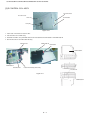
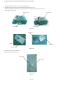
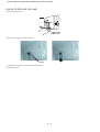
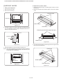
1
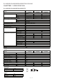
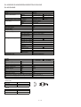
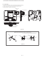
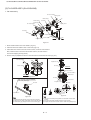
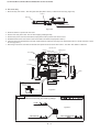
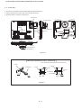
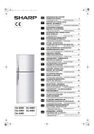
SJ-A20S/B21S/A24S/B25S/A28A/B27S/A31S/A34S-SL
SERVICE MANUAL
No.S9902SJ22FTVTT
Refrigerator-freezer
MODELS
Ag
SJ-F230G
SJ-F230G
SJ-F230G
SJ-A28S-SL
SJ-B27S-SL
SJ-A20S-SL
SJ-B21S-SL
SJ-A24S-SL
SJ-B25S-SL
SJ-A28S-SL
SJ-B27S-SL
SJ-A31S-SL
SJ-A34S-SL
DESTINATION
T
Refrigerant; HFC-134a
Refer to "HFC-134a COOLING UNIT" Service Manual for handling this refrigerant.
CONTENTS
CHAPTER 1. SPECIFICATION
[1] SJ-A20S/B21S/A24S/B25S/A28S/B27S........ 2-1
[2] SJ-A31S/A34S .......................................... 2-2
CHAPTER 2. DESIGNATION OF VARIOUS PARTS
[1] EXTERNAL DESCRIPTION........................... 2-1
[2] CONSTRUCTIONS........................................ 2-2
CHAPTER 3. DIMENTIONS
[1] OUTER DIMENTIONS AND
CLEARANCE ................................................. 3-1
[2] INNER DIMENTIONS .................................... 3-4
CHAPTER 4. LIST OF ELECTRICAL PARTS
CHAPTER 5. WIRING DIAGRAM
[1] WIRING DIAGRAM ........................................ 5-1
[2] ELECTRIC ACCESSORIES LAYOUT ........... 5-2
[3] PRECAUTION FOR USING LEAD-FREE
SOLDER........................................................5-3
CHAPTER 6. FAILURE DIAGNOSIS
[1] OUTLINE OF CONTROL ............................... 6-1
[2] CHECK MODE OF DEFROST HEATER
(Forced Defrosting) ........................................ 6-1
[3]
[4]
[5]
[6]
RE-SETTING OF MICROCOMPUTER AT
POWER FAILURE.......................................... 6-2
DIAGNOSIS METHOD OF FAILURE ............6-2
CONVERSION TABLE ..................................6-3
CIRCUIT DIAGRAM OF MAIN PWB .............6-4
CHAPTER 7. FUNCTIONS
[1] ADJUSTABLE TEMPERATURE
CONTROL .....................................................7-1
CHAPTER 8. ASSEMBLI NG PROCEDURES OF
MAIN PARTS AND CAUTIONS
[1] F-LOUVER ASS'Y (SJ-A20S/B21S/A24S/
B25S/A28S/B27S)..........................................8-1
[2] F-LOUVER ASS'Y (SJ-A31S/A34S)...............8-4
[3] R CONTROL COV. ASS'Y.............................8-7
[4] HOW TO REPLACE THE LAMP ...................8-9
[5] DEFROST HEATER ......................................8-10
CHAPTER 9. COOLING UNIT
[1] COOLING UNIT.............................................9-1
[2] LOCATION ....................................................9-2
Parts Guide
This document has been published to be used for
after sales service only.
The contents are subject to change without notice.
!"#$% &'$( &#$) &'$* &#$+ &'$, &#-( &#-)
SJD34NSLG
CHAPTER 1. SPECIFICATION
Service Manual
SJ-A20S/B21S/A24S/B25S/A28S/B27S
SJ-A20S
SJ-A24S
SJ-B21S
SJ-B25S
Type
2-Door
Outer dimensions
Height
1253mm(49.3")
1389mm(54.7")
Width
545mm(21.5")
545mm(21.5")
Depth
620mm(24.4")
620mm(24.4")
Rate storage volume (Rated volume)
184liter(6.5cu.ft) 212liter(7.5cu.ft)
Heater system
Defrosting
System
Automatic
Start
Automatic
Finish
Temperature control
Automatic (Adjustable)
No-frost freezer
Yes
Interior lamp
1
Evaporating pan
1
1
Freezer Compartment
F-shelf
Twin ice cube maker
Ice cube maker
1
Ice storage box
1
Door pocket
1
Refrigerator Compartment Fresh case
R shelf (plastic)
1
2
R shelf ass'y (glass) V shelf (plastic)
1
1
V shelf ass'y (glass) 1
Vegetable case
1
Egg pocket
1
Small pocket
1
Door pocket B
1
Bottle pocket
1
Door pocket
Deodorizing unit
1 (Honeycomb type)
Stand
Yes
SJ-A28S
SJ-B27S
Items
1491mm(58.7")
545mm(21.5")
620mm(24.4")
227liter(8.0cu.ft)
2
2
1
RATING
SJ-A20S
SJ-B21S
Items
Rated voltage
(V~)
Rated frequency
(Hz)
Climate class
Rated power input
(W)
Rated current
(A)
Current input
(A)
Defrosting input
(A)
Defrosting power
(W)
Refrigerant (Charging quantity) [Non-flammable]
Insulation blowing gas [Flammable]
Net Weight
(kg)
220
50
T
100
0.58
0.85
0.58
128
HFC-134a(75 g) HFC-134a(75 g)
Cyclo pentane (HC)
39
41
PLUG TYPE
Plug cord
Plug type
Destination mark
2 pin
T
COLOR
Items
Outside color
Inside color
-SL
Silver
White
SJ-A24S
SJ-B24S
1–1
SJ-A28S
SJ-B27S
HFC-134a(95 g)
45
!"#$% &'$( &#$) &'$* &#$+ &'$, &#-( &#-)
SJD34NSLG
SJ-A31S/A34S
Service Manual
SJ-A31S
SJ-A34S
2-Door
Height
1580mm(62.2")
1700mm(66.9")
Width
600mm(23.6")
600mm(23.6")
Depth
631mm(24.8")
631mm(24.8")
Rated storage volume (Rated volume)
292liter(10.3cu.ft) 313liter(11.1cu.ft)
Heater system
Defrosting
System
Automatic
Start
Automatic
Finish
Temperature control
Automatic (Adjustable)
No-frost freezer
Yes
Interior lamp
1
Evaporating pan
1
1
Freezer Compartment
F-shelf
Twin ice cube maker
Ice cube maker
1
Ice storage box
2
Door pocket
1
Refrigerator Compartment Fresh case
R shelf ass'y (glass) 2
3
V shelf ass'y (glass) 1
1
Vegetable case
1
Egg pocket
1
Egg tray
Small pocket
1
2
1
Door pocket B
1
Bottle pocket
1
Door pocket
1 (Honeycomb type)
Deodorizing unit
Items
Type
Outer dimensions
RATING
Items
Rated voltage
(V~)
Rated frequency
(Hz)
Climate class
Rated power input
(W)
Rated current
(A)
Current input
(A)
Defrosting current
(A)
Defrosting power
(W)
Refrigerant (Charging quantity) [Non-flammable]
Insulation blowing gas [Flammable]
Net Weight
(kg)
SJ-A31S
220
50
T
109
0.58
0.95
0.58
128
HFC-134a(100 g)
Cyclo pentane (HC)
52
54
PLUG TYPE
Plug cord
Plug type
Destination mark
2 pin
T
COLOR
Items
Outside color
Inside color
-SL
Silver
White
1–2
SJ-A34S
!"#$% &'$( &#$) &'$* &#$+ &'$, &#-( &#-)
SJ26NSL
CHAPTER 2. DESIGNATION OFVARIOUS Service
PARTSManual
[1] EXTERNAL DESCRIPTION
The names in parenthesis "[
]" are the denominations used in the REPLACEMENT PARTS LIST.
1
12
2
3
13
4
14
5
15
6
16
7
17
18
8
19
9
1. Freezer shelf [F-shelf]
2. Freezer temp.control knob
3. Ice cube maker
4. Ice cube box [Ice storage box]
5. Fresh room
6. Refrigerator temp.control knob
7. Light [Lamp]
8. Refrigerator shelf
[ R-shelf (plastic) : SJ-A20S/B21S; 1 pc.
SJ-A24S/B25S; 2 pcs.
R-shelf ass’y (glass) :SJ-A28S/B27S/A31S;
2 pcs, SJ-A34S; 3 pcs.]
9. Vegetable shelf
[ R-shelf (plastic) : SJ-A20S/B21S/A24S/B25S,
R-shelf (glass) : SJ-A28S/B27S/A31S/A34S ]
10. Vegetable crisper [Vegetable case]
11. Adjustable foot [Adjustable leg]
12. Magnetic door seal [Door packing]
13. Door pocket
10
13
(SJ-A20S/B21S/A24S/B25S; 2 pockets,
SJ-A28S/B27S/A31S/A34S; 3 pockets)
14. Egg holder [Egg tray]
11
12
15. Egg pocket
16. Light switch
17. Small pocket (right) [Small pocket]
(Only SJ-A31S/A34S)
(SJ-A24S/B25S/A28S/B27S/A31S; 1 pocket,
SJ-A34S; 2 pockets)
18. Small pocket (left) [Door pocket B]
(SJ-A24S/B25S/A28S/B27S/A31S/A34S)
19. Bottle pocket
2–1
!"#$% &'$( &#$) &'$* &#$+ &'$, &#-( &#-)
[2] CONSTRUCTIONS
Mark: Cold air flow
Fan motor
F-temp. control knob
Def-thermistor
Evaporator
Fuse ass'y
Defrost heater
Deodorizing unit
R-temp. control knob
R-thermistor
PWB L ass'y
Lamp
Running capacitor
Evaporating pan
Compressor
Starting relay
Protector
2–2
!"#$% &'$( &#$) &'$* &#$+ &'$, &#-( &#-)
SJD26LVSL
CHAPTER 3. DIMENTIONS
[1] OUTER DIMENTIONS AND CLEARANCE
1. SJ-A20S/B21S
60
628.5
610
60
60
545
443.5
545
1145
34
4
757.5
1085
1253
9
365
970
(Unit:mm)
2. SJ-A24S/B25S
60
628.5
610
60
60
545
9
443.5
545
1145
34
4
893.5
1085
1389
365
970
(Unit:mm)
3–1
!"#$% &'$( &#$) &'$* &#$+ &'$, &#-( &#-)
3. SJ-A28S/B27S
60
628.5
610
60
60
545
9
515.5
545
1145
34
4
923.5
1085
1491
365
970
(Unit:mm)
4. SJ-A31S
649.5
631
600
9
541.5
600
34
4
986.5
1065
3–2
1221
1161
1580
405
!"#$% &'$( &#$) &'$* &#$+ &'$, &#-( &#-)
5. SJ-A34S
649.5
631
600
9
34
4
1106.5
1161
1700
405
1065
[2] INNER DIMENTIONS
1. SJ-A20S/B21S
196
366
154
380
143
107
103
390
45
340
204
66
138
67
55 33
38
391
146
250
107
211
208
253
366
208
417
120
149
371
300
292
321
43
417
80
67
137
363
(Unit:mm)
3–3
1221
541.5
600
!"#$% &'$( &#$) &'$* &#$+ &'$, &#-( &#-)
2. SJ-A24S/B25S
38
55 33
366
66
154
138
45
143
103
390
340
107
67
380
204
196
391
187
91
30
292
271
371
154
120
107
417
86
417
292
434
68
211
208
253
366
208
43
417
214
250
169
180
80
137
67
363
(Unit:mm)
3. SJ-A28S/B27S
366
67
66
202
366
66
154
138
45
143
107
103
390
204
254
196
67
55 33
38
391
169
292
464
120
184
271
123
292
371
107
211
417
208
253
366
80
208
417
91
30
68
43
417
144
214
250
180
67
137
363
(Unit:mm)
3–4
!"#$% &'$( &#$) &'$* &#$+ &'$, &#-( &#-)
4. SJ-A31S
416
67
66
231
66
154
45
92
107
67
111
445
217
68
30
43
472
380
237
91
312
312
330
472
147
180
170
55 33
416
138
204
254
217
530
38
430
430
107
210
120
231
472
217
217
259
430
80
152
67
411
5. SJ-A34S
416
67
66
231
66
154
30
68
237
155
30
59
43
472
91
380
91
312
312
472
312
650
472
147
150
155
237
180
155
45
92
107
67
111
445
170
55 33
416
138
335
430
107
160
120
282
217
430
80
217
231
480
67
152
411
204
254
217
170
38
430
3–5
!"#$% &'$( &#$) &'$* &#$+ &'$, &#-( &#-)
SJ26NSL
CHAPTER 4. LIST OF ELECTRICAL PARTS
ITEMS
R Thermistor
Defrost Thermistor
TYPE NAME
―
―
RATING
DC 5V
DC 5V
SPECIFICATIONS
R0 = 6.4 kΩ, B(0) = 3811
R0 = 6.4 kΩ, B(0) = 3811
Thermo. fuse
SF70E
Defrost heater
―
Fan motor
(A20S/B21S/A24S/B25S/ 3R00121
A28S/B27S)
250V 10A
220 - 240V 378Ω
Working temp. : 70 °C
140W at 230V
(A31S/A34S)
3R00101B
AC 220-240V,50Hz ―
AC 220-230V,60Hz
Door switch
SDKNA20101
250V 0.25A
125V 0.5 A
240V 15W
R Lamp
―
Compressor
(A20S/B21S/A24S/B25S) FL0845-ST
AC 200-240V, 50Hz ―
3 Terminals push-botton type
#187 Straight Terminal, Pitch 6
220-240V/50Hz
Cooling capacity : 106 W (50Hz)
Main coil : 23.8 Ω
Aux. coil : 29.7 Ω
(at 75 °C)
(A28S/B27S)
FL1152-SZ
220-240V/50Hz
Cooling capacity : 136 W (50Hz)
Main coil : 23.8 Ω
Aux. coil : 42.4 Ω
(at 75 °C)
(A31S/A34S)
FL1257-SW
220-240V/50Hz
Cooling capacity : 170 W (50Hz)
Main coil : 18.4 Ω
Main coil
Aux. coil
Aux. coil : 31.5 Ω
(at 75 °C)
Common
Starting Relay
PEN0SBT
Overload Relay(Protector)
50/60 Hz
22 ± 4.4Ω (at 25 °C)
(A20S/B21S/A24S/B25S) 5TM158RFBYY-53 ―
Open/ Close : 120 ± 0.5 / 61 ± 9.0°C
5TM149NFBYY-53 ―
Open/ Close : 120 ± 0.5 / 61 ± 9.0°C
(A31S/A34S)
5TM189RFBYY-53 ―
(A31S/A34S)
Running capacitor
(A20S/B21S/A24S/B25S/ RC-EZA237CBZZ ―
A28S/B27S)
RC-EZA249CBZZ ―
(A31S/A34S)
Open/ Close : 130 ± 0.5 / 61 ± 9.0°C
Main PWB
―
(A28S/B27S)
FPWB-A667CBKZ 220-240V
4–1
400V 3 F
400V 4 F
!"#$% &'$( &#$) &'$* &#$+ &'$, &#-( &#-)
SJD26LVSL
CHAPTER 5. WIRING DIAGRAM
[1] WIRING DIAGRAM
Be sure to replace the electrical parts with specified ones for maintaining the safety and performance of the set.
COMPRESSOR
STARTING RELAY
(BL)
RUNNING CAPACITOR
5–1
!"#$% &'$( &#$) &'$* &#$+ &'$, &#-( &#-)
[2] ELECTRIC ACCESSORIES LAYOUT
F-LOUVER ASS’Y
CABINET
FAN MOTOR FM
LEAD EV COVER
HARNESS FL ASS’Y
FUSE
DEF-THERMISTOR
DEF-HEATER
R-CBOX-K
PWB
LAMP
R-THERMISTOR
DOOR SWITCH
TERMINAL COVER
PROTECTOR
COMPRESSOR
RUN CAP.
RELAY WIRE ASS’Y
STARTING RELAY
(BOTTOM ANGLE)
5–2
!"#$% &'$( &#$) &'$* &#$+ &'$, &#-( &#-)
[ ] PRECAUTIONS FOR USING LEAD-FREE SOLDER
1. Employing lead-free solder
The PWB of this model employs lead-free solder. This is indicated by the "LF" symbol printed on the PWB and in the service manual. The suffix letter
indicates the alloy type of the solder.
Example:
Indicates lead-free solder of tin, silver and copper
2. Using lead-free wire solder
When repairing a PWB with the "LF" symbol, only lead-free solder should be used. (Using normal tin/lead alloy solder may result in cold soldered
joints and damage to printed patterns.)
As the melting point of lead-free solder is approximately 40°C higher than tin/lead alloy solder, it is recommend that a dedicated bit is used, and that
the iron temperature is adjusted accordingly.
3. Soldering
As the melting point of lead-free solder (Sn-Ag-Cu) is higher and has poorer wettability, (flow), to prevent damage to the land of the PWB, extreme
care should be taken not to leave the bit in contact with the PWB for an extended period of time. Remove the bit as soon as a good flow is achieved.
The high content of tin in lead free solder will cause premature corrosion of the bit. To reduce wear on the bit, reduce the temperature or turn off the
iron when it is not required.
Leaving different types of solder on the bit will cause contamination of the different alloys, which will alter their characteristics, making good soldering
more difficult. It will be necessary to clean and replace bits more often when using lead-free solder. To reduce bit wear, care should be taken to clean
the bit thoroughly after each use.
5-3
!"#$% &'$( &#$) &'$* &#$+ &'$, &#-( &#-)
SJ431NSL
CHAPTER 6. FAILURE DIAGNOSIS
Service Manual
[1] OUTLINE OF CONTROL
1. ON/OFF Control of Compressor
When the plug of refrigerator is connected, the compressor will start automatically and run for approximately 5 minutes. After then, ON/OFF of the
compressor will be controlled depend on the temperature detected by the R-thermistor. During 6 minutes after the compressor stops, it will not start
regardless of the detected temperature by R-thermistor..
2. Defrosting
Microcomputer calculates the appropriate timing of defrosting and defrosting is made automatically. Therefore no manual operation by user is
required. The cycle of defrosting varies depend on the usage condition of the refrigerator. (Maximum time 50 hours, minimum time 4 hours)
3. Thermistor
Thermistors are installed in 2 places; in the refrigerator compartment and close to the
Evaporator. (R-thermistor and Def-thermistor)
It is not installed in the freezer compartment.
Def-thermistor
R-thermistor reads the temperature in the refrigerator compartment and controls ON/OFF
of compressor.
Evaporator
Def-thermistor detects the temperature around the evaporator and shows the progress of
defrosting.
Defrost heater
R-thermistor
PWB
Compressor
[2] CHECK MODE OF DEFROST HEATER (Forced Defrosting)
The operation of the defrost heater can be checked by starting it.
In case the failure of defrosting is suspected, this is an effective inspection method.
1. Starting Method
At the power OFF condition.
1) Keep the door of the refrigerator compartment open.
2) Set the Temp. Control Knob in the refrigerator compartment to the following position.
220-240V models: Center
(Center)
110-127V models: Max
3) Keep the door open and supply power source.
2. Normal Operation
1) Approximately 3 seconds after power supply, the relay on the PWB will be turned ON and the defrost heater will be electrified for 5 seconds.
2) After 5 seconds, if the temperature of Def-thermistor reaches high enough (over 10°C) and judged as defrosting completion, the compressor runs
for 5 minutes and then returns to the normal control.
On the other hand, if the temperature of Def-thermistor is still low (under 10°C), the defrost heater will be electrified until the temperature of Defthermistor reaches the specified temperature or higher.
After completion of electrification, the compressor runs for 5 minutes and then returns to the normal control.
*
In the case that any abnormality in Door Switch, Volume, R-thermistor or Def-thermistor, or the Temp. Control Knob is not in the position corresponding to the value of the rating voltage settled to the PWB itself, this mode will not be entered nor the defrost heater is electrified.
6–1
!"#$% &'$( &#$) &'$* &#$+ &'$, &#-( &#-)
[3] RE-SETTING OF MICROCOMPUTER AT POWER FAILURE
•
At the power failure for over 0.1 second, the control of the microcomputer will be reset.
When the power is re-supplied, the temperature of R-thermistor will be detected again and ON/OFF of the compressor will be decided.
•
At the momentary power failure (less than 0.1 second), the protector of the compressor might work due to the high load to the compressor for restarting.
•
When resetting is made during the operation of the defrost heater, the normal cooling will be resumed.
[4] DIAGNOSIS METHOD OF FAILURE
Check by the following procedure;
1. Disconnect power supply and check the following point.
•
Is there any failure portion in inserting connectors?
2. Detach the PWB and check the appearance.
•
Is there any burning or abnormal damage?
3. Check the conditions of the fuse and the varistor. (Fuse and varistor are located at the position in the figure.)
•
Melting in the fuse cannot be checked visually (as the safer one than transparent glass tube is used). Be sure to detach the connector “CN1”
before measuring the resistance between the both ends of the fuse by the tester.
•
Next, measure the resistance value between the both leads of the varistor.
Varistor
Fuse
Varistor→
Fuse↓
Melting
Conduction
Normal (several hundreds Ω~several KΩ)
D a m a ge
Flow of excessive current is considerable for some reasons.
Check for any portion to cause short circuits especially
on the primary circuit.
Fuse and varistor are normal.
Possibility to be caused by excessive current or voltage
near the power supply is low. Proceed to the next check
item.
There is a possibility of excessive voltage applied from outside with the factor such as thunder etc. When repeated
with a factor other than thunder, there might be the apparatus near by generating noises.
—
4. Check whether the temperature (resistance value) shown by R-thermistor is correct or not. (Refer to the table below.)
•
Detach the connector “CN3” on the PWB and measure the resistance value between 1 and 2 pins.
5. Check whether the temperature (resistance value) shown by Def-thermistor is correct or not. (Refer to the table below.)
•
Detach the connector “CN3” on the PWB and measure the resistance value between 3 and 4 pins.
6–2
!"#$% &'$( &#$) &'$* &#$+ &'$, &#-( &#-)
[5] CONVERSION TABLE
Conversion Table between R-thermistor and Def-thermistor Temperature and Resistance Value
Temperature
(°C)
-25
-24
-23
-22
-21
-20
-19
-18
-17
-16
-15
-14
-13
-12
Resistance Value
(kΩ)
26.1
24.54
23.08
21.72
20.46
19.27
18.16
17.13
16.16
15.25
14.4
13.6
12.85
12.15
Temperature
(°C)
-11
-10
-9
-8
-7
-6
-5
-4
-3
-2
-1
0
1
2
Resistance Value
(kΩ)
11.49
10.88
10.3
9.75
9.24
8.76
8.3
7.87
7.47
7.09
6.74
6.4
6.08
5.78
6–3
Temperature
(°C)
3
4
5
6
7
8
9
10
11
12
13
14
15
Resistance Value
(kΩ)
5.5
5.23
4.98
4.74
4.52
4.3
4.1
3.91
3.73
3.56
3.4
3.24
3.1
!"#$% &'$( &#$) &'$* &#$+ &'$, &#-( &#-)
[6] CIRCUIT DIAGRAM OF MAIN PWB
6–4
!"#$% &'$( &#$) &'$* &#$+ &'$, &#-( &#-)
SJD26LVSL
CHAPTER 7. FUNCTIONS
[1] ADJUSTABLE TEMPERATURE CONTROL
1. Temperature control
1) FREEZER COMPARTMENT
The FREEZER TEMP. CONTROL regulates the quantity of cold air to the freezer.
"MAX" setting directs more cold air to the freezer compartment. (making the freezer compartment colder)
"MIN" setting directs less cold air to the freezer compartment. (making the freezer compartment less colder)
KNOB
SETTING
MAX
PURPOSE
For making ice rapidly of fast freezing. And winter season.
When restocking with fresh food.
For normal freezing.
For storing frozen food for a short period (up to one month).
When frozen food or ice cream is not stored.
MID
FREEZER TEMP.CONTROL
MIN
2) REFRIGERATOR COMPARTMENT
The REFRIGERATOR TEMP. CONTROL controls the compressor running time of the refrigeration system.
"Coldest"(5) setting will result in colder temperature in the both (refrigerator and freezer) compartments.
"MIN"(1) control setting will result in warmer temperature in the both (refrigerator and freezer) compartment.
PURPOSE
KNOB
SETTING
For keeping freshness of food longer.
When the refrigerator does not provide sufficient cooling.
For normal operation.
When the refrigerator provides excessive cooling.
MAX
(Center)
MIN
REFRIGERATOR
TEMP.CONTROL
When refrigerator temperature control sets to the "MAX", some foods stored
may become frozen. In this case adjust control set back to the center position.
NOTE:
•
For hot summer conditions (about over 35 °C ambient temperature), set your FREEZER TEMP. CONTROL to less colder than "MID"
(towards "MIN"). This is because "MAX" setting may result in too little air flow to the refrigerator compartment, causing too warm temperature in the refrigerator compartment. And set your refrigerator compartment freeze, you must set the REFRIGERATOR TEMP. CONTROL
to less colder setting. (toward "MIN").
•
In a cold kitchen (about under 10 °Cambient temperature), set your FREEZER TEMP. CONTROL to "MAX" to avoid too warm temperature in the freezer compartment. This is because the compressor operation is too short in winter, and not enough cold air is provided to
the freezer compartment. And if the foods in the refrigerator compartment freeze, you must set the REFRIGERATOR TEMP. CONTROL to
less colder setting. (toward "MIN").
•
With the FREEZER TEMP. CONTROL set to "MAX" , there will be less cold air directed to the refrigerator compartment, and the refrigerator compartment may not become cold enough.
2. Reference value of temperature
SETTING OF
FREEZER TEMP.
CONTROL KNOB
MAX
(Coldest)
Freezer
temperature
Approx.
MID
Approx.
MIN
Approx.
SETTING OF
REFRIGERATOR TEMP.
CONTROL KNOB
Refrigerator
temperature
MAX
(Coldest)
(Center)
MIN
Approx.
Approx.
Approx.
The values shown above refer to the case where the The values shown above refer to the case where the
freezer temp. control knob is set at the center position.
refrigerator temp. control knob is set at "MID".
The values tables above refer to the measurement carried out center area and 1/3 of overall height from the bottom at each of the refrigerator and the
freezer after the machine has been operated at an ambient temperature of 32 °C with no food stored and the door closed until the temperature is stabilized.
The values vary depending upon frequency of opening and closing, the doors ambient temperature, amount of stored foods and manner of storing
foods.
7–1
!"#$% &'$( &#$) &'$* &#$+ &'$, &#-( &#-)
3. Temp. control system
Freezer Temp. Control Knob
The FREEZER TEMP. CONTROL regulates the quantity of cold air to the freezer.
MAX setting directs more cold air to the freezer compartment.
(making the freezer compartment colder)
MIN setting directs less cold air to the freezer compartment.
(making the freezer compartment less colder)
Fan
Cold air
Coldest
FREEZER
COMPARTMENT
Coldest
Evaporator
much cold air
less cold air
FREEZER
COMPARTMENT
regulating the quantity
of cold air.
regulating the quantity
of cold air.
REFRIGERATOR
COMPARTMENT
REFRIGERATOR
COMPARTMENT
Compressor
less cold air
much cold air
Refrigerator Temp. Control Knob
The REFRIGERATOR TEMP. CONTROL controls the
compressor & the fan running time of the refrigerator system.
MAX setting will result in colder temperature in the both
(refrigerator and freezer) compartments.
MIN control setting will result in warmer temperature in the
both (refrigerator and freezer) compartments.
high cold power
low cold power
FREEZER
COMPARTMENT
REFRIGERATOR
COMPARTMENT
controlling the compressor
& the fan running time
controlling the compressor
& the fan running time
Normal operation (ex. at 20 C ambient temperature)
Temp.( C)
30
OFF ON OFF ON
Compressor & Fan
20
Ambient temperature
10
0
Refrigerator compartment temperature (at the center position)
-10
-20
Time
Freezer compartment temperature (at MID position)
7–2
!"#$% &'$( &#$) &'$* &#$+ &'$, &#-( &#-)
SJD26LVSL
CHAPTER 8. ASSEMBLING PROCEDURES OF MAIN PARTS AND CAUTIONS
CAUTION: DISCONNECT THE UNIT FROM THE POWER SUPPLY BEFORE ANY REPAIRING.
[1] F-LOUVER ASS'Y (SJ-A20S/B21S/A24S/B25S/A28S/B27S)
1. Fan motor ass'y
Propeller fan 90
Fan motor holder a
Fan clamp
Lead EV-cover
Slit area
Motor cushion
U-sealer handle
Fan motor holder b
Motor cushion
Fan motor
U-sealer handle
Figure A-1
1. Stick U-sealer handle to Fan motor holder b (Fig. A-2).
2. Insert the terminal of Lead EV-cover to Fan motor (Fig. A-3).
3. Insert shaft of Fan motor to the hole of motor cushion, set at Fan motor holder b.
Then insert the boss of rear to the hole of Motor cushion, fix with Tapping screw(1 piece).
4. Set Fan clamp to propeller fan 90 mm. and then insert it to the shaft of Fan motor( Fig. A-4).
U-sealer handle
Fan motor holder b
Propeller fan 90
SEC. A-A
Fan clamp
Detail of D
Fan motor holder a
Fan motor holder b
U-sealer handle
Fan motor holder b
Motor cushion
Figure A-2
Fan clamp
Motor cushion
WIRE COLOR IS GRAY/ORANGE
Propeller fan 90
(127V : with yellow tape)
Fan motor
Fan motor
Lead EV-cover
slit
Fan clamp
slit
GOOD
Figure A-3
Note
(1) Assemble so that terminal of Fan motor does not deform.
(2) Take care not to stress to terminals of Fan motor after wiring.
(3) Check locking by pulling them with more than 10N(1 kgf).
NO GOOD
Figure A-4
Note
(1) Slit of each Fan Clamp and propeller fan 100 should not be at same
position.
(2) Fan clamp should be inserted virtically to the end of boss.
(3) Propeller fan should not be taken out from shaft when pulled by 2 kgf.
8–1
!"#$% &'$( &#$) &'$* &#$+ &'$, &#-( &#-)
2. EV-cover ass'y
1. Bind Fuse ass'y with L-band c. Then wind glass cloth tape (W25 x L50mm ) to lead wire of Fuse ass'y (Figure A-5).
L-band c
Fuse ass’y
Glass cloth tape
W25xL50
Figure A-5
2. Stick EVC-sealer a to square hole of EV-cover.
3. Set Fan motor ass'y to EV-cover. Then Fix with 2 tapping screw(Figure A-6) .
4. Set Fuse ass'y to EV-cover then stick aluminum tape (W39 x L35mm) and EV-cover al to EV-cover.
5. Set Def-thermistor to EV-cover and fix to Fan motor holder b with aluminum tape (W39 x L50mm ).
6. Insert the terminal of Def-thermistor to terminal No.5/No.6 and then insert the Fuse ass'y to the terminals No.1/No.2. on the 6P connector of Lead
EV-cover (Figure A-7).
7. After wiring at rear of EV-cover take out lead wire from square hole to front and fix with L-band c. Then stick EVC-sealer b to lead wire.
Lead EV-cover
L-band c
EVC-sealer a
Tapping screw
Fan motor ass’y
T
Tapping screw
Def-thermistor
EVC-sealer b
Fuse ass’y
Tapping screw
Stick Al-tape
from here
L-band c
L-band c
EV-cover al
Aluminum tape
W39xL135
Glass cloth tape
W25xL50
SEC. D-D
Stick EV-cover al
from this line
Note
Lead wire of Fuse ass’y must not over
EV-cover.
Figure A-6
SCALE 2:1
PL Process Note
Pins should be inserted surely, and check by pulling it.
FUSE
(BLACK)
(BLUE)
Figure A-7
DEF THERMISTOR
FAN MOTOR
(WHITE)
(GRAY/ORANGE)
8–2
!"#$% &'$( &#$) &'$* &#$+ &'$, &#-( &#-)
3. F - louver ass'y
1. Set F-louver to front side of EV-cover with double face tape (W15xL45mm.).
2. Insert F-control knob to F-louver. Then set to front side of EV-cover.
3. Stick EVC-sealer c to bottom of F-louver ass'y.
Lead EV-cover
more than 3.5mm.
more than 3.5mm.
Fan motor holder a
F-louver
F-louver
Fan motor holder b
F-control knob
F-control knob
Double face tape
W15xL45
EV-cover
NO CLEARANCE
EVC-sealer c
F-louver
EV-cover
Fan motor holder a
Fan motor holder b
Figure A-8
Attachment specification of the F-control knob
The F-control knob is inserted into the ditch of the fan louver.
F-louver
F-louver
F-control knob
arm A
F- louver
EV-cover
EV- cover
F-control knob
F-control knob
arm A
arm B
arm B
SEC. B-B
Figure A-9
8–3
SEC. C-C
!"#$% &'$( &#$) &'$* &#$+ &'$, &#-( &#-)
[2] F-LOUVER ASS'Y (SJ-A31S/A34S)
1. Fan motor ass'y
Fan motor holder b
Tapping screw
Motor cushion
Motor cushion
Fan motor
U-sealer handle
Fan motor holder a
Tapping screw
Slit area
Fan clamp
U-sealer handle
Lead EV-cover
BROWN
RED
Propeller fan 100
Figure A-1
1. Stick U-sealer handle to Fan motor holder a (Fig. A-2).
2. Insert the terminal of Lead EV-cover to Fan motor (Fig. A-3).
3. Insert shaft of Fan motor to the hole of motor cushion, set at Fan motor holder a.
Next, insert the boss of rear to the hole of Motor cushion, set at fan motor b.
Then fix with Tapping screw (2 pieces).
4. Set Fan clamp to propeller fan 100 mm. and then insert it to the shaft of Fan motor( Fig. A-4).
Fan motor holder a
Fan motor holder a
Propeller fan 100
U-sealer handle
Fan clamp
Detail of D
Fan motor holder a
U-sealer handle
Fan motor holder b
SEC. C-C
Motor cushion
Figure A-2
Fan clamp
WIRE COLOR IS GRAY/ORANGE
Motor cushion
(127V : with yellow tape)
Propeller fan 100
Fan motor
Fan motor
slit
Fan clamp
slit
Lead EV-cover
GOOD
Figure A-3
Note
(1) Assemble so that terminal of Fan motor does not deform.
(2) Take care not to stress to terminals of Fan motor after wiring.
(3) Check locking by pulling them with more than 10N(1 kgf).
Note
NO GOOD
Figure A-4
(1) Slit of each Fan Clamp and propeller fan 100 should not be at same
position.
(2) Fan clamp should be inserted virtically to the end of boss.
(3) Propeller fan should not be taken out from shaft when pulled by 2 kgf.
8–4
!"#$% &'$( &#$) &'$* &#$+ &'$, &#-( &#-)
2. EV-cover ass'y
1. Bind Fuse ass'y with L-band c. Then wind glass cloth tape (W25 x L50mm ) to lead wire of Fuse ass'y (Figure A-5).
L-band c
Fuse ass’y
Glass cloth tape
W25xL50
Figure A-5
2. Stick EVC-sealer a to square hole of EV-cover.
3. Set Fan motor ass'y to EV-cover. Then Fix with 3 tapping screw(Figure A-6) .
4. Set Fuse ass'y to EV-cover then stick aluminum tape (W39 x L35mm) and EV-cover al to EV-cover.
5. Set Def-thermistor to EV-cover and fix to Fan motor holder b with aluminum tape (W39 x L50mm ).
6. Insert the terminal of Def-thermistor to terminal no.5/No.6 and then insert the Fuse ass'y to the terminals No.1/No.2. on the 6P connector of Lead
EV-cover (Figure A-7).
7. After wiring at rear of EV-cover take out lead wire from square hole to front and fix with L-band c. Then stick EVC-sealer b to lead wire.
Lead EV-cover
L-band c
EVC-sealer a
Tapping screw
Fan motor ass’y
Tapping screw
Def-thermistor
EVC-sealer b
Fuse ass’y
Aluminum tape
W39xL50
Tapping screw
Stick Al-tape
from here
L-band c
L-band c
EV-cover al
Aluminum tape
W39xL135
Glass cloth tape
W25xL50
SEC. D-D
Stick EV-cover al
from this line
Note
Lead wire of Fuse ass’y must not over
EV-cover.
Figure A-6
SCALE 2:1
PL Process Note
Pins should be inserted surely, and check by pulling it.
FUSE
(BLACK)
(BLUE)
Figure A-7
DEF THERMISTOR
FAN MOTOR
(WHITE)
(GRAY/ORANGE)
8–5
!"#$% &'$( &#$) &'$* &#$+ &'$, &#-( &#-)
3. F - louver ass'y
1. Set F-louver to front side of EV-cover with double face tape (W15xL45mm.).
2. Insert F-control knob to F-louver. Then set to front side of EV-cover.
3. Stick EVC-sealer c to bottom of F-louver ass'y.
Lead EV-cover
more than 3.5mm.
more than 3.5mm.
Fan motor holder a
F-louver
F-louver
Fan motor holder b
F-control knob
F-control knob
Double face tape
W15xL45
EV-cover
NO CLEARANCE
EVC-sealer c
F-louver
EV-cover
Fan motor holder a
Fan motor holder b
Figure A-8
Attachment specification of the F-control knob
The F-control knob is inserted into the ditch of the fan louver.
F-louver
F-louver
F-control knob
arm A
F- louver
EV-cover
EV- cover
F-control knob
F-control knob
arm A
arm B
arm B
SEC. B-B
Figure A-9
8–6
SEC. C-C
!"#$% &'$( &#$) &'$* &#$+ &'$, &#-( &#-)
[3] R CONTROL COV. ASS'Y
R-Control knob
R-C Box cover
Control label
Lamp
Figure A-10
1. Insert Lead R-Thermistor to Lead R-C Box.
2. Inset Lead R-C box to PWB L ass'y.
3. Assemble the PWB L ass’y with PWB holder A and then assemble the PWB holder A with PWB holder B.
4. Stick the R-control AL on PWB holder A/B ass’y.
Lead R-C Box
PWB holder B
Lead sealer
PWB holder A
PWB holder A
Lead R-C Box
Lead R-Thermistor( White wire)
R-control AL
Figure A-11
PWB holder B
8–7
!"#$% &'$( &#$) &'$* &#$+ &'$, &#-( &#-)
5. Assemble Lamp with R-C Box cover then fix with 2 tapping screw.
6. Stick Knob sealer on R-C Box cover and then insert Knob joint to R-C Box cover.
7. Assemble the PWB ass'y with R-C Box cover. And place the R-Thermistor on the groove of R-C Box cover.
8. Insert Lead R-C Box to Lamp.
R-C Box cover
R-C Box cover
Knob joint
Knob sealer
Figure A-12
PWB holder
Lamp
R-Thermistor
R-C Box cover
Figure A-13
9. Insert R-Control knob to R-C Box cover.
10.Stick Control Label on R-C Box cover.
Control label
R-Control knob
Figure A-14
8–8
!"#$% &'$( &#$) &'$* &#$+ &'$, &#-( &#-)
[4] HOW TO REPLACE THE LAMP
1. Remove the Light cover.
2. Remove the 2 screw, and pull the Lamp out.
Screw
3. Insert the new Lamp to the connector, and fix with 2 screws.
4. Set the Light cover.
8–9
!"#$% &'$( &#$) &'$* &#$+ &'$, &#-( &#-)
[5] DEFROST HEATER
2. Replacement of Def. heater.
1. Taking-out Evaporator
1. Remove the aluminium tape on Heater support to take it off from
the food liner.
1. Take-out Fan louver ass’y.
2. Raise the protrusion part of Heater support. Then remove Heater
cover.
2. Take-out E.V cover ass’y.
Protrusion parts
Evaporator
Heater support
Food liner convex part
Figure A-15
Heater cover
3. As shown in Figure A-15, pull the upper part of Evaporator toward
you, pull it diagonally so that the pipe of Evaporator does not contact the convex part of food liner.
Protrusion part of Drain support al(2 pcs.)
Food liner convex part
Evaporator
Def. heater ass'y
Pipe
Heater cover
Figure A-18
3. Open Def.heater fixed part of Heater support al to the right and left,
then remove Def.heater ass’y.
Figure A-16
4. Pull the Evaporator for remove as shown in Figure A-16.
NOTE: When pulling Evaporator and bending the pipes,pay attention
so as not to break and deform the pipes. Still, take care not to
hurt yourself by fin of Evaporator.
Fixed parts
Heater support
Evaporator
Def.heater ass’y
Figure A-17
Figure A-19
8 – 10
!"#$% &'$( &#$) &'$* &#$+ &'$, &#-( &#-)
3. Installing of Evaporator
4. Replace Def. heater ass’y with new one.
1. Install Evaporator as shown in Figure.A-15 in the reverse order of
Figure.A-16.
Heater cover
2. Correct the deformed fin.
NOTE: 1.When installing Evaporator, take care not to deform significantly and break the pipes.
Def. heater ass'y
2.Take care not to damage the lead wires and hurt yourself by
the fin of Evaporator.
3.You shouldn’t touch Defrost Heater with your bare hand.
(you should were pure gloves)
4.You should wipe that with alcohol. When you touch Defrost
heater with your bare hand.
Heater support
Figure A-20
5. Bend end of heater support 90.
BEND
BEND
Heater Support
Figure A-21
6. Assemble Defrost heater to Heater Support.
7. Assemble Heater cover to Heater Support. Bend top edge to outside.
4P
Defrost Heater
Heater support
Figure A-22
8. Roll the leading wire Sealer to Lead wire Defrost Heater.
4P
BEND
BEND
Figure A-23
8 – 11
!"#$% &'$( &#$) &'$* &#$+ &'$, &#-( &#-)
SJ26NSL
CHAPTER 9. COOLING UNIT
Service Manual
[1] COOLING UNIT
NOTE: The iron pipe is partly used of this refrigerator. Please note the following points when brazing the iron pipe.
•
Brazing material should be silver brazing rod. (To be equivalent with BAg-20 or BAg-7)
•
Flux should be FB3A type. (It should be non-chlorine type).
•
Place an iron plate or cloth on the base frame to prevent the flux fall.
•
Remove the paint and plating on the pipe by the sandpaper before start repairing.
•
If you cut the iron pipe for repairing, remove the plating on the iron pipe end (20mm) by the sandpaper.
•
Put the flux on silver brazing rod and dry the flux by the flame of the torch, and then start brazing.
•
Remove the flux completely by the wire brush , and wipe off by the cloth after brazing.
•
Leakage inspection should be done when compressor is running.
•
After removing flux, paint the black enamel paint on the brazing part.
Mark: Refrigerant flow
Mark: Brazing portion
Hot pipe L
(Side condenser)
Hot pipe
(DP-condenser)
Hot pipe R
(Side condenser)
Back condenser
Evaporator
Suction pipe
Copper pipe
Discharge P connector
S.P connector
Compressor
Iron pipe
Capillary tube
Dryer connector
Dryer
*
Copper back condenser is used in some models.Before repairing,check the Back condenser is copper or iron.
9–1
!"#$% &'$( &#$) &'$* &#$+ &'$, &#-( &#-)
[2] LOCATION
1. Location 1
Dryer
Capillary tube
Dryer connector
Hot pipe
Charge pipe
Evaporator
Charge pipe L
Back condenser
*
Suction pipe
S.P
Discharge
connector
P connector
Compressor
Mark shows Cu brazing points
Mark shows Ag brazing points
2. Location 2
Discharge P. connector
to Back condenser
*
Back condenser
to Hot pipe
Pinch Point
D.P. butyl
Pinch point
Dryer connector
to Dryer
Hot pipe
to Dryer connector
Charge pipe
to Dryer
S.P connector
to Compressor's
suction tube
Suction butyl
Charge pipe L
to Compressor's
process tube
Compressor's discharge pipe
to Discharge P. connector
Dryer
to Capillary tube
S.P connector
to Suction pipe
Mark shows Cu brazing points
Mark shows Ag brazing points
*
Copper back condenser is used in some models.Before repairing,check the Back condenser is copper or iron.
9–2