1
L NUMBER
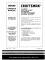
917.257720
OWNER'SMANUAL
Assembly
Operation
Customer Responsibilities
Service and Adjustments
Repair Parts
CAUTION:
Read
and follow
all safety
rules and instructions
before
operating
this equipment,
SAFETY
Practices RULES
for Ride-On
Safe Operation
Mowers
IMPORTANT: THIS CUTTING MACHINE IS CAPABLE OFAMPUTATING HANDSAND FEETAND THROWING OBJECTS.
FAILURE TO OBSERVE THE FOLLOWING SAFETY INSTRUCTIONS COULD RESULT IN SERIOUS INJURY OR DEATH.
L
GENERAL
*
Read, understand, and follow all instructions in the manual
and on the machine before starting.
Only allow responsible adults, who are familiar with the
instructions, to operate the machine.
Clear the area of objects such as rocks, toys, wire, etc.,
which could be picked up and thrown by the blade.
Be sure the area is clear of other people before mowing. Stop
machine if anyone enters the area.
Never carry passengers.
Do not mow in reverse unless absolutely necessary. Always
look down and behind before and while backing.
*
,
-
=
®
OPERATION
Stop engine before removing grass catcher or unclogging
chute.
o
o
Mow only in daylight or good artificial light.
Do not operate the machine while under the influence of
alcohol or drugs.
Watch for traffic when operating near or crossing roadways.
Use extra care when loading or unloading the machine into
a trailer or truck.
IL
Tragic accidents can occur if the operator is not alert to the
presence of children. Children are often attracted to the machine
and the mowing activity. Neverassume that children will remain
where you last saw them.
*
*
Be aware of the mower discharge direction and do not point
it at anyone. Do not operate the mower without either the
entire grass catcher or the guard in place.
Slow down before turning.
Never leave a running machine unattended. Always turn off
blades, set parking brake, stop engine, and remove keys
before dismounting.
Turn off blades when not mowing.
®
-
t11. CHILDREN
,
Before and when backing, look behind and down for small
children.
,
Never carry children. They may fall off and be seriously
injured or interfere with safe machine operation.
Never allow children to operate the machine.
Use extra care when approaching blind corners, shrubs,
trees, or other objects that may obscure vision.
*
IV. SERVICE
-
•
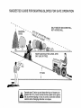
SLOPE OPERATION
Slopes are a major factor related to loss-of-control and tipover
accidents, which can result in severe injury or death. All slopes
require extra caution. If you cannot back up the slope or ifyou feel
uneasy on it, do not mow it.
,
DO:
•
o
*
®
®
o
Mow up and down slopes, not across.
Remove obstacles such as rocks, tree limbs, etc.
,
,
Watch for holes, ruts, or bumps.
Uneven terrain could
overturn the machine. Tafl grass can hide obstacles.
Use slow speed. Choose a low gear so that you will not have
to stop or shift while on the slope.
Follow the manufacturer's
recommendations
for wheel
weights or counterweights to improve stability.
Use extra care with grass catchers or other attachments.
These can change the stability of the machine.
Keep all movement on the slopes slowand gradual Do not
make sudden changes in speed or direction.
Avoid starting or stopping on a slope. If tires lose traction,
disengage the blades and proceed slowly straight down the
slope.
-
.
,
Use extra care in handling gasoline and other fuels. They are
flammable and vapors are explosive.
Use only an approved container.
Never remove gas cap or add fuel with the engine
running. Allow engine to cool before refueling. Do not
smoke.
Never refuel the machine indoors.
Never store the machine or fuel container inside where
there is an open flame, such as a water heater.
Never run a machine inside a closed area.
Keep nuts and bolts, especially blade attachment bolts, tight
and keep equipment in good condition.
Never tamper with safety devices.
Check their proper
operation regularly.
Keep machine free of grass, leaves, or other debris build-up.
Clean oil or fuel spillage. Allow machine to cool before
storing.
Stop and inspect the equipment if you strike an object.
Repair, if necessary, before restarting.
Never make adjustments or repairs with the engine running.
Grass catcher components are subject to wear, damage, and
deterioration, which could expose moving parts or allow
objects to be thrown. Frequently check components and
replace with manufacturer's recommended parts, when nec o
essary.
Mower blades are sharp and can cut. Wrap the blade(s) or
wear gloves, and use extra caution when servicing them.
Check brake operation frequently.
Adjust and service as
required.
Look for this symbol to point out important safety precautions.
It means
CAUTION!!! BECOME ALERT!!! YOUR
SAFETY IS INVOLVED.
DO NOT:
,
Keep children out ofthe mowing area and under the watchful
care of another responsible adult.
Be alert and turn machine off if children enter the area.
Do not turn on slopes unless necessary, and then, turn slowly
and gradually downhill, if possible.
Do not mow near drop-offs, ditches, or embankments. The
mower could suddenly turn over if a wheel is over the edge
of a cliff or ditch, or if an edge caves in.
Do not mow on wet grass. Reduced traction could cause
sliding.
Donottrytostabilizethemachinebyputtingyourfootonthe
ground.
Do not use grass catcher on steep slopes.
CAUTION:
Always disconnect
spark
plug wire and place wire where it cannot
contact spark plug in order to prevent
accidental
starting when setting up,
transporting,
adjusting
or making
repairs,
2
PRODUCT
CONGRATULATIONS
on your purchase of a Sears
Tractor. It has been designed, engineered and manufactured to give you the best possible dependability and
performance.
Should you experience any problem you cannot easily
remedy, please contact your nearest Sears Authorized
Service Center/Department.
We have competent, welltrained technicians and the proper tools to service or repair
this unit.
Please read and retain this manual. The instructions will
enable you to assemble and maintain your unit properly.
Always observe the "SAFETY RULES".
MODEL
NUMBER
917.257720
SPECIFICATIONS
HORSEPOWER:
18.0
GASOM NE CAPACITY
AND TYPE:
3,5 GALLONS
UNLEADED REGULAR
OIL TYPE (API-SG):
SAE 30 (above 32°F)
SAE 5W-30 (below 32°F)
OILCAPACITY:
W/FILTER:
W/O FILTER:
SPARK PLUG:
(GAP: .025")
CHAMPION
RV17YC
VALVE CLEARANCE:
INTAKE:
EXHAUST:
.003" - .006"
.016" - .019"
GROUND SPEED (MPH):
Forward
1st
2nd
3rd
Reverse
TRANSAXLE OIL
CAPACITY AND TYPE:
4 QUARTS
SAE 30 API-SG
TIRE PRESSURE:
FRONT:
REAR:
CHARGING SYSTEM:
15 AMPS @ 3600 RPM
BLADE BOLT TORQUE:
30-35 FT. LBS.
SERIAL
NUMBER
DATEOFPURCHASE
THE MODELANDSERIALNUMBERS
ON A PLATE UNDER THE SEAT.
WILL BE FOUND
YOU SHOULD RECORD BOTH SERIAL NUMBER AND
DATE OF PURCHASE AND KEEP IN A SAFE PLACE
FOR FUTURE REFERENCE.
MAINTENANCE
AGREEMENT
A Sears Maintenance
Agreement
uct. Contact your nearest Sears
CUSTOMER
o
Read and observe
Follow a regular schedule
using your unit.
the safety
is available on this prodstore for details.
rules.
in maintaining,
Ht
1.8
3.4
5.6
2.2
14PSI
10 PSI
In the state of California the above is required by law
(Section 4442 of the California Public Resources Code).
Other states may have similar laws. Federal laws apply on
federal lands. A spark arrester for the muffler is available
through your nearest Sears Authorized Service Center/
Department (See REPAIR PARTS section of this manual).
caring for and
Follow the instructions
under "Customer
Responsibilities" and "Storage"
sections of this owner's manual.
LmMR'ED TWO YEAR WARRANTY
L.O
0.8
1.4
2.4
0.9
WARNING: This unit is equipped with an internal combustion engine and should not be used on or near any unimproved forest-covered, brush-covered
or grass-covered
land unless the engine's exhaust system is equipped with
a spark arrester meeting applicable local or state laws (if
any). If a spark arrester is used, it should be maintained in
effective working order by the operator.
RESPONSNBILmTIES
o
4.0 PINTS
3.5 PINTS
ON ELECTRIC
START RIDING EQUIPMENT
For two (2) years from the date of purchase, if this riding equipment is maintained, lubricated and tuned up according to the
instructions in the owner's manual, Sears will repair or replace, free of charge, any parts found to be defective in material or
workmanship.
This Warranty does not cover:
o
o
o
Expendable items which become worn during normal use, such as blades, spark plugs, air cleaners and belts.
Tire replacement or repair caused by punctures from outside objects, such as nails, thorns, stumps, or glass.
Repairs necessary because of operator abuse, negligence, improper storage or accident or the failure to maintain the
equipment according to the instructions contained in the owner's manual:
Riding equipment used for commercial or rental purposes.
LIMITED 90 DAY WARRANTY
ON BATTERY
For ninety (90) days from date of purchase, if any battery included with this riding equipment proves defective in material or
workmanship and our testing determines the battery will not hold a charge, Sears will replace the battery at no charge.
WARRANTY SERVICE
CENTER/DEPARTMENT
tS AVAILABLE BY RETURNING
IN THE UNITED STATES.
THE RIDING
EQUIPMENT
TO THE NEAREST
SEARS SERVICE
This Warranty gives you specific legal rights, and you may also have other rights which may vary from state to state.
SEARS,
ROEBUCK
AND CO., D/817 WA, HOFFMAN
3
ESTATES,
ILLINOIS
60179
TA
SAFETY
RULES
PRODUCT
LE OF CON
............................................................
SPECIFICATIONS
MAINTENANCE SCHEDULE ......................................
15
SERVICE AND ADJUSTMENTS ............................ 19-25
STORAGE ....................................................................
26
TROUBLESHOOTING ............................................
28=29
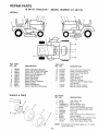
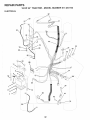
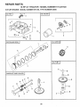
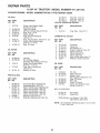
REPAIR PARTS =TRACTOR ................................. 31-47
REPAIR PARTS - ENGINE ..................................... 48°57
PARTS ORDERING/SERVICE ................ BACK COVER
2
.......................................
3
CUSTOMER
RESPONSIBILITIES
.....................
3, 15-18
WAR RANTY ...................................................................
3
TRACTOR
ACCESSORIES
...........................
................ 5
ASSEMBLY
..............................................................
7-10
OPERATION
...........................................................
11-14
INDEX
E
A
Accessories
...........................................
TS
5
Adjustments:
Brake ............................................
21
Carburetor ....................................
25
Clutch Pulley ................................ 21
Gauge Wheels .............................
13
Mower
Front-To-Back ........................ 20
Side-To-Side ........................... 19
Throttle Control Cable .................. 25
Air Filter, Engine ..................................
18
Air Screen. Engine ............................... 18
Assembly ..........................................
7-10
Electrical:
Interlocks and Relays ................... 22
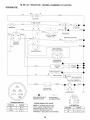
Schematic ..................................... 30
Wiring Diagram ............................. 32
Engine:
Air Filter ........................................
18
Air Screen ..................................... 18
Cooling Fins ................................. 18
Oil Change ...................................
17
Oil Level .......................................
17
Oil Type ..................................
13,17
Preparation ...................................
13
Repair Parts ............................ 48-57
Starting .................................... 13.14
Storage .........................................
26
Operation ........................................
11-14
Operating Mower ................................. 13
Options:
Accessories .................................... 5
Spark Arrester ........................... 3,38
P
Parking Brake ................................. 11-12
Parts Bag ...............................................
6
Parts, Replacement/Repair
............ 31-47
Product Specifications ........................... 3
R
Repair Parts ...................................
3! -47
B
Battery:
Charging .........................................
8
Cleaning .......................................
16
Installation ....................................
10
Levels ........................................
8.16
Preparation .....................................
8
Starting with Weak Battery ........... 21
Storage .........................................
24
Terminals ......................................
17
Belt:
Motion Drive
Removal/Replacement
............ 22
Mower Drive
Removal/Replacement
............ 20
Mower Blade Drive
Removal/Replacement
............ 21
Blade:
Sharpening ...................................
16
Replacement ................................ 16
Brake Adjustment ................................ 21
26
14
22
H
L
Leveling Mower Deck ..........................
19
Lubrication:
Chart .............................................
Engine ..........................................
15
16
M
25
21
11
Customer Responsibilities .............. 15-18
Engine:
Air Filter ....................................
18
Air Screen .................................
18
Cooling Fins ............................. 18
Engine Oil ............................ 13,16
Fuel Filter .................................
18
Spark Plug(s) ............................. 18
Tractor:
Battery .....................................
17
Blade ........................................
14
Lubrication Chart ...................... 15
Maintenance Schedule ............. 15
Tire Care .......................... 8,15,21
Transaxle ..................................
16
Cutting Height, Mower .........................
18
18
18
Headlights ............................................
24
Hood Removal/Installation ................... 24
C
Carburetor Adjustment .......................
Clutch Pulley ........................................
Controls. Tractor ..................................
S
F
Filter:
Air Filter ........................................
Fuel ..............................................
Oil .................................................
Fuel:
Storage .........................................
Type .............................................
Fuse ....................................................
12
Maintenance
Schedule ........................
Mower:
Adjustment, Front-to-Back ............
Adjustment, Side-to-Side ..............
lade Replacement ......................
Blade Sharpening .........................
Cutting Height ...............................
Installation ....................................
Operation ......................................
Removal .......................................
15
19
19
16
16
12
19
13
19
Mowing Tips ........................................
14
Muffler ..................................................
18
Spark Arrester ........................... 3,38
O
Oil:
Cold Weather Conditions ........ 13.17
Engine ..........................................
17
Storage ......................................... 26
4
Safety Rules ..........................................
Seat ......................................................
2
8
Service and Adjustments ................ 19-25
Carburetor .................................... 25
Clutch Pulley ................................ 21
Fuse ............................................
23
Hood Removal/Installation
........... 24
Motion Drive Belt
Removal/Replacement
............ 22
Mower Drive Belt
Removal/Replacement
............ 20
Mower Blade Drive Belt
Removal/Replacement
............ 21
Mower Adjustment
Front-to-Back ........................... 20
Side-to-Side ............................. 19
Mower Removal/Installation
......... 18
Tire Care ............................... 8.15,21
Slope Guide Sheet .............................. 59
Spark Plug(s) .......................................
17
Specifications ........................................
3
Starting the Engine ......................... 13-14
Steering Wheel ................................. 7,22
Stopping the Tractor ............................ 12
Storage ................................................
26
T
Throttle Control Cable Adjustment ...... 25
Tires .............................................
8.15.21
Troubleshooting Chart ................... 28-29
Transax_e ...................................
16.46-47
W
Warranty ................................................
WiringDiagram
....................................
Wiring Schematic .................................
3
32
30
ESSORIES AND ATTAC
These accessories
Most Sears stores
and attachments
can order these
were available through most Sears retail outlets and service centers
items for you when you provide the model number of your tractor.
when the tractor
was purchased.
MAINTENANCE
ENGINE
SPARK
ENTS
PLUG
GAS CAN
FUEL STABiLiZER
BLADES
BELTS
PERFORMANCE
Sears offers a wide variety of attachments that fit your tractor.
you. This list was current at the time of publication; however,
may be made in these attachments, or some may no longer
accessories
and attachments
that are available for your
Most of these attachments
attaching and detaching.
Many of these are listed below with brief explanations of how they can help
it may change in future years - more attachments may be added, changes
be available or fit your model. Contact your nearest Sears store for the
tractor.
do not require additional hitches or conversion
AERATOR promotes deep root growth for a healthy lawn. Tapered
2.5-inch steel spikes mounted on 10-inch diameter discs puncture
holes in soil at close intervals to let moisture soak in. Steel weight tray
for increased penetration_
BUMPER
protects
front end of tractor from damage.
SLEEVE HITCH for use with master
uncouples.
DISC HARROW has 2 gangs of 4 steel blades that angle from 10 to
20 degrees, 40 inches wide. Can hook 2 units in tandem.
(Requires
sleeve hitch,)
OHL DRAIN
VALVE
makes
SPREADER/SEEDERS
make seeding, fertilizing, and weed killing
easy. Broadcast spreaders are also useful for granular de-icers and
sand.
SWEEPERS
easier, faster.
FRONT NOSE ROLLER canters in front of mower
chances of "scalping" on uneven terrain.
deck to reduce
MULCH RAKE/DETHATCHER
loosens soil and flips thatch and
matted leaves to lawn surface for easy pickup. Twenty spring tine
teeth. Useful to prepare bare areas for seeding. Available for front or
rear mounting.
HiGH PERFORMANCE
REEL=ACTION
SPRING
TINE DETHATCHER
covers 36-inch wide path and tosses thatch into
large hopper. Mounts behind tractor.
grass clippings
and leaves.
TiRE CHAINS are heavy duty; closely spaced
give smooth ride, outstanding
traction.
extra-large
cross links
TRACTOR CAB has heavy duty vinyl fabric over tubular steel frame,
ABS plastic top; clear plastic windshield offers 360 degree visibility.
Hinged metal doors with catch.
Keeps operator warm and dry.
Remove vinyl sides and windshields
for use as sun protector in
summer,
OptionaJ
accessories
incUude:
tinted/tempered
solid
safety glass windshield
with hand operated wiper; 12-volt amber
caution light for mounting on cab top.
PLOW turns soil 6 inches deep, cuts 10-inch furrow. Crank adjustment controls depth, 3-position yoke sets width. Heavy steel lands!de
for straight furrowing.
(Requires sleeve hitch.)
tractor
let you collect
TILLER has 8 hp engine to prepare seed beds, cultivate, and compost
garden residue. Chain-drive transmission.
Six 11-inch diameter one
piece heat-treated steel tines. Tills 30-inch path. (Requires sleeve
hitch.) Or use 5 hp tow-behind TILLER with 36-inch swath to prepare
seed beds, cultivate and compost garden residue. Tiller has its own
built-in lift and depth control system and does NOT require a sleeve
hitch. Fits any lawn, yard or garden tractor. Simply hook up to the
tractor drawbar and go! OptionaU accessories
for 5 hp tiller convert
unit for dethatching,
aerating, hilling...without
tools.
GANG HF['OH lets you tow 2 or 3 pUll*behind attachments
at
once, such as sweepers,
dethatchers,
aerators (not for use with
rollers, carts or other heavy attachments).
RAMP TOPS AND FEET let you load and unload
pickup truck. Use with 2 x 8 or 2 x 10 lumber.
Single pin couples/
SPRAYERS
use 12wott DC electric motor that connects to the tractor
battery or other 12wolt source.
Includes
booms for automatic
spraying and hand held wand for spot spraying. Wand has adjustable
spray pattern. For applying herbicides, insecticides,
fungicides and
liquid fertilizers.
dirt, sand and gravel. 48
path when angled. Master
trip for snow removal on
to follow ground contour,
with tire chains and wheel
oil changes
lift system.
SNOWTHROWER
has 42-inch swath.
Drum-type auger handles
powdery and wet/heavy snow. Mounts easily with simple pin arrangement. Discharge chute adjusts from tractor seat. 6qnch diameter
spout discharges snow 10 to 50 feet. Lift controlled at tractor seat.
(Use with chains and wheel weights and/or rear drawbar weight.)
CORING AERATOR
takes small plugs out of soil to allow moisture
and nutrients to reach grass roots. 36-inch swath. 24 hardened steel
coring tips. 150 lb. capacity weight tray.
EASY
and are designed for easy
SLEEVE
CULTWATOR
is 43 inches wide. Prepares
ground for
seeding, helps weed control. Steel frame holds 5 adjustable sweeps.
Adjusts vertically, horizontally.
(Requires
sleeve hitch.)
Optional
accessory:
steel furrow opener for wider openings for potatoes,
corn, and other deep-seeded
crops.
CARTS make hauling easy. Variety of sizes available, plus accessories such as side panel kits, toot caddy, cart cover, protective mat and
dolly.
DOZER BLADE removes snow; grades
inches wide, 17 inches high, clears 44-inch
lift control lever for operator ease. Spring
uneven pavement; built-in float for blade
Reversible, replaceable scraper bar. (Use
weights and/or rear drawbar weight.)
kits (those that do are indicated)
from a
REAR GRADER BLADE is 42 inches wide and operated from driver's
seat. Reversible steel blade can be angled at 30 degrees for grading.
Reverses for pushing snow backwards.
(Requires sleeve hitch.)
VACS for powerful collection of heavy grass clippings and leaves.
Optional wand attachment
to pick up debris in hard-to=reach places_
VAC/CHIPPER
includes a chipper-shredder.
ROLLER for smoother lawn surface. 36-inch wide, 18-inch diameter
water-tight
drum holds up to 390 Ibm. of weight.
Rounded edges
prevent harm to turf. Adjustable scraper automatically
cleans drum.
WEIGHT BRACKET for drawbar for snow removal applications,
can
be mounted on front of tractor for plowing applications.
Uses (1) 55
lb. weight.
WHEEL
removal
5
WEIGHTS for rear wheels provide
or dozing heavy materials.
needed traction
for snow
CONTENTS
Parts Bag contents
,OF
E PACK
shown full size
Parts packed separately
.........
3
.....
.-
in carton
=
=
Seat
(1) Shoulder Bolt 5/16-18
Battery acid
©
(1) Knob
Battery
Steering Wheel
(1) Washer
I 1
17/32 x 1-3/!6 x 12 Gauge
Double Loop
etainer Springs
_
Owner's Manual
Parts Bag
=
Parts bag contents
_
.
not shown
full size
=
(2) Gauge Wheels
©
(2)
(4) Retainer Springs
Single Loop
(2) Shoulder
_t
(2) Hex Bolts 1/4-20 x 3/4
(2) Washers Lock Nuts
3/8 x 7/8 x 14 Gauge
Bolts
Link Assemblies
(2) Battery Carriage Bolts 1/4-20 x 7-1/2
(2) Hex Nuts 1/4-20
Steering
Sleeve
Terminal Guard
(2) Washers
9/32 x 5/8 x 16 Ga.
(2) Lock Washers
Steering Wheel insert
1/4
(2) Keys
/
\
r
(2) Wing Nuts
1/4-20
15° Slope Sheet
......
6
=
Battery Caps
and Instructions
BLY
Your newtractor has been assembled at the factory with the exception of those parts left unassembled for shipping purposes,
To ensure safe and proper operation of your tractor all parts and hardware you assemble must be tightened securely. Use
the correct tools as necessary to insure proper tightness,
TOOLS REQUIRED
FOR ASSEMBLY
STEERING
WHEEL iNSERT
A socket wrench set will make assembly easier. Standard
wrench sizes are listed.
(2) 7/16" wrenches
_jHEX
Tire pressure gauge
(1) 1/2" wrench
Utility knife
(1) 9/16" wrench
,_!;,_//
(1) 3/4" socket with drive ratchet
When right or left hand is mentioned in this manua, it
means when you are in the operating position (seated
behind the steering wheel).
TO REMOVE TRACTOR
UNPACK
STEERING
WHEEL
FROM CARTON
CARTON
®
Remove all accessible loose parts and parts cartons
from carton (See page 6).
®
Cut, from top to bottom, along lines on all four corners
of carton, and lay panels flat.
o
Remove mower and packing materials.
o
Check for any additional
remove.
STEERING
SHAFT
STEERING
SLEEVE
loose parts or cartons and
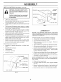
BEFORE ROLLING TRACTOR OFF SKID
ATTACH
STEERING
WHEEL
(See Fig. 1)
*
Remove hex bolt, lock washer and large flat washer
from steering shaft.
,
Position front wheels of the tractor so they are pointing
straight forward,
o
Slide steering sleeve over steering shaft,
o
Position steering wheel so cross bars are horizontal
(left to right) and slide onto steering wheel adapter.
o
Secure steering wheel to steering shaft with hex bolt,
Iockwasher and large flat washer previously removed
Tighten securely.
Snap steering
wheel.
FIG. 1
wheel insert into center of steering
Remove protective
plastic from tractor hood and grill.
IMPORTANT:
CHECK FOR AND REMOVE ANY STAPLES
IN SKID THAT MAY PUNCTURE TIRES WHERE TRACTOR
IS TO ROLL OFF SKID.
TO ROLL TRACTOR
OFF SKiD (See Fig, 7)
o
Raise attachment
o
Release parking brake by depressing clutch/brake
pedal.
Place gearshift lever in neutral (N) position.
Rol! tractor backwards off skid,
®
BOLT
LOCK WASHER
lift lever to its highest position.
7
LARGE FLAT
WASHER
ASSEM
HOW TO SET UP YOUR TRACTOR
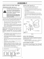
PREPARE
BATTERY
CAUTION:
LY
INSTALL
SEAT (See Fig. 3)
Adjust seat before tightening adjustment knob.
(See Fig, 2)
Remove cardboard packing on seat pan.
Wear eye and face shield.
Wash Hands or clothing immediately if
accidentally in contact with battery acid.
Do not smoke.
Fumes from charged
battery acid are e×pmosive.
Read the instructions included with the
battery vent caps. Always wear gloves,
c_othing and goggles to protect your
Hands, skin and eyes.
o
Place seat on seat pan and assemble shoulder bolt.
•
Assemble adjustment
Do not tighten.
,
Tighten shoulder bolt securely.
•
Lower seat into operating position and sit on seat.
o
Slide seat until a comfortable position is reached which
allows you to press clutch/brake pedal all the way
down.
o
Get off seat without moving its adjusted position.
o
Raise seat and tighten adjustment knob securely.
Your tractor has a battery charging system which is sufficient for normal use. However, periodic charging of the
battery with an automotive charger wilt extend its life.
o
SEAT
See instructions packed with vent caps in parts bag.
SEAT PAN
Fill battery with acid. Fill each cell until it reaches the
bottom of the vent wells. Do not overfill.
While battery is standing (after adding acid) and later, while
battery is being charged, continue with assembly of unit.
iMPORTANT:
TO MAXIMIZE
THE LIFE OF YOUR
BATTERY,
IT IS NECESSARY
THAT THE BATTERY
BE
CHARGED
BEFORE
USE.
FAILURE
TO CHARGE
BATTERY
CAN RESULT
IN A SHORTENED
BATTERY
LIFE.
o
FLAT WASHER
ADJUSTMENT
KNOB
Charge battery at a rate of 6 amperes for 1 hour. Use
a 12 volt battery charger. Observe all safety precautions required for battery charging.
FIG. 3
Check the acid level after the battery is charged. If the
acid has fallen below the correct level, add distilled or
iron free water_
CHECK
Check battery case for leakage to make sure that no
damage has occurred in handling.
•
Dispose of excess battery acid. Neutralize acid for
disposal by adding it to two gallons of water in a five
gallon plastic container. Stir with a wooden or plastic
paddle while adding baking soda unti! the addition of
more soda causes no more foaming.
o
Follow instructions
I_
_-_]>._
•
_@/
FiG. 2
CELL
BRAKE
SYSTEM
After you learn how to operate your tractor, check to see
that the brake is properly adjusted. See "TO ADJUST
BRAKE" in the Service and Adjustments section of this
manual.
_ VENT CAP
_
Reduce tire pressure to PSI shown in "PRODUCT
SPECIFICATIONS" on page 3 of this manual.
CHECK
on how to install battery.
CUT AWAY ViEW
TIRE PRESSURE
The tires on your tractor were overinflated at the factory for
shipping purposes. Correct tire pressure is important for
best cutting performance.
Install the vent caps to cover the vent wells. Wash the
top of the battery with water to remove any acid, then
wipe dry.
®
\
SHOULDER
BOLT
Allow battery to stand and settle for at least thirty
minutes. After standing, check the battery cell acid
level. If below the vent wells, add more acid until the
correct level is reached.
o
knob and flat washer loosely.
ACiD
8
LY
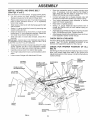
INSTALL
MOWER
AND DRIVE BELT
o
(See Figs. 4 and 7}
Be sure tractor is on level surface. Engage parking brake.
o Cut and remove tie down securing anti-sway bar.
Swing anti-sway bar to left side of mower deck.
,
Relieve idler tension from belt. Push idler forward and
place a block (standard wood 2 x 4 or equivalent)
behind idler pulley.
® Slide mower under tractor with discharge guard to right
side of tractor.
-
®
•
o
Swing L.H. gauge wheel bar forward by removing rear
retainer spnng and pin.
Install one front link in top hole of the L.H. front mower
bracket and L.H. front suspension bracket. Retain with
two single loop retainer springs as shown.
Slide right side of mower deck forward, toward R.H.
front tire.
IMPORTANT: CHECK BELT FOR PROPER ROUTINGIN
ALL MOWER PULLEY GROOVES. INSTALL BELT INTO
ELECTRIC CLUTCH PULLEY GROOVE.
o
•
o
o
®
Place the suspension arms on inward pointing deck
pins. If necessary, rock and raise front of mower to
align deck pins with the holes in suspension arms.
Retain with double loop retainer springs.
Connect anti-sway bar to chassis bracket under left
footrest and retain with double loop retainer spring.
Turn height adjustment knob clockwise to remove
slack from mower suspension.
Raise deck to highest position.
Swing L.H. gauge wheel bar back towards rear of
mower and secure with pin and retainer spnng removed earlier.
Assemble gauge wheels as shown using long shoulder
bolts, 3/8 washers and nuts. Tighten securely.
Adjust gauge wheels before operating mowerasshown
in the Operation section of this manual.
CHECK
DECK LEVELNESS
For best cutting results, mower housing should be properly
leveled. See "TO LEVEL MOWER HOUSING" in the
Service and Adjustments section of this manual.
Install second front link in the top hole of the R.H. front
mower bracket and R.H front suspension bracket.
Retain with two single loop retainer springs as shown.
Carefully remove block from behind idler pulley.
Turn height adjustment knob counterclockwise unti! it
stops.
Lower mower linkage with attachment lift lever.
CHECK
BELTS
FOR
PROPER
POSiTiON
OF ALL
See the figures that are shown for replacing motion, mower
drive, and mower blade drive belts in the Service and
Adjustments section of this manual. Verify that the belts are
routed correctly.
FRONT
CHASSIS
BRACKET
\
\
\
DOUBLE LOOP
RETAINER SPRING
\
\
L.H. GAUGE
WHEEL
BAR
SUSPENSION
ARMS
DOUBLE LOOP
RETAINER SPRING
(inward pointing
deck pins)
BRACKET
FRONT
LINKS
CLUTCH
PULLEY
\
"_
FRONT
SUSPENSION
BRACKET
SHOULDER
BOLT
LOOP RETAINER
SPRINGS
FRONT MOWER
BRACKET
NUT
ANTI-SWAY
BAR
3/8 WASHER
iDLER
PULLEY
BLOCK
(Wood2x4orequiv.)
GAUGE
WHEEL
DISCHARGE
GUARD
F_Go4
9
t
ASSEMBLY
INSTALL
BATTERY
(See Figs, 5 and 6)
CAUTION: Do not short battery terminares°Before installing battery, remove
metam bracelets,
wristwatch bands,
rings, etc°
Positive terminal must
first to prevent sparking
tal grounding.
ACCESS
DOORS
be connected
from accidenKEY
HOLE
\
VENT
CAPS
\
-
Lift hood to raised position.
o
Be sure battery drain tube has not come loose and is
securely attached to drain in battery tray.
o
Lower battery into battery tray with terminals to front of
tractor.
o
First connect RED battery cable to positive (+) battery
terminal with hex bolt, flat washer, lock washer and hex
nut as shown. Tighten securely.
o
Connect BLACK grounding cable to negative (-) battery
terminal with remaining hex bolt, flat washer, lock
washer and hex nut. Tighten securely.
o
Slide the two battery bolts through the terminal guard
and start the wing nuts onto the threads.
°
Position terminal guard over battery as shown, lower
battery bolts into key holes and slide square shafts of
battery bolts into slots of key holes.
o
BATTERY
FIG. 6
v" CHECKMST
BEFORE YOU OPERATE AND ENJOY YOUR NEW
TRACTOR, WE WISH TO ASSURE THAT YOU RECEIVE
Tt lE BES T PERFORMANCE AND SA TISFA CTION FROM
THIS QUALITY PRODUCT,
PLEASE REVIEW THE FOLLOWING CHECKLIST:
Tighten wing nuts by hand making sure battery bolts
reman in slots of the key holes in the battery support.
Be sure terminal access doors are closed.
Use terminal access doors for:
•
Inspection for secure connections
ware).
®
Testing battery.
o
Jumping (if required).
o
Periodic charging.
(to tighten hard-
Inspection for corrosion.
FLAT WASHER
/
(POSITWE)
/ /
/ RED CABLE
HEX
TRAY
,/
All assembly instructions have been completed.
¢'
No remaining loose parts in carton.
v'
Battery is properly prepared and charged.
1 hour at 6 amps).
,/
Seat is adjusted comfortably and tightened securely.
,/
All tires are properly inflated. (Forshipping
the tires were overinfiated at the factory).
v"
Be sure mower deck is properly leveled side-to-side/
front-to-rear for best cutting results. (Tires must be
properly inflated for leveling).
,/
Check mower and drive belts. Be sure they are routed
properly around pulleys and inside all belt keepers.
v"
Check wiring. See that all connections are still secure
and wires are properly clamped.
(Minimum
purposes,
WHILE LEARNING HOW TO USE YOUR TRACTOR,
PAY EXTRA A TTEN TION TO THE FOL L 0 WING IMPORTANT ITEMS:
HEX BOLT
NEGATIVE)
BLACK CABLE
,/
Engine oil is at proper level.
,/
Fuel tank is filled with fresh clean, regular unleaded
gasoline.
Become familiar with all controls - their location and
function. Operate them before you start the engine.
v"
DRAIN TUBE
v"
LOCK WASHER
FtGo 5
10
Be sure brake system is in safe operating condition.
ERATION
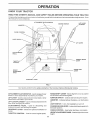
KNOW YOUR TRACTOR
READ THiS OWNER'S
MANUAL
AND SAFETY
RULES
BEFORE
OPERATING
YOUR
TRACTOR
Compare the illustrations with your tractor to familiarize yourself with the locations of various controls and adjustments, Save
this manual for future reference,
ATTACHMENT
CLUTCH SWITCH
\
iGNiTiON
LiFT LEVER
SWITCH
AMMETER
CHOKE
CONTROL
LIGHT SWITCH
LIFT LEVER
CLUTCH/BRAKE
PEDAL
PARKING
LEVER
THROTTLE
CONTROL
BRAKE
RANGE SHIFT
LEVER
HEIGHT
ADJUSTMENT
KNOB
#
GEARSHIFT
/
/
/
/
/
./
LEVER
FIG, 7
Our tractors conform to the safety standards of the American National Standards Institute.
ATTACHMENT CLUTCH SWITCH- Used to engage mower
blades or other attachments mounted to your tractor.
UFT LEVER- Used to raise and lower mower deck or other
attachments mounted to your tractor.
RANGE SHIFT LEVER - Allows high (H) or low (L) speed
for all forward and reverse gears.
LIFT LEVER PLUNGER - Used to release attachement lift
lever when changing its position.
(4.
UGHT SWITCH - Turns the headlights on and off.
CLUTCH!BRAKE
PEDAL - Used for declutching
braking the tractor and starting the engine.
PARKmNG BRAKE LEVER - Locks clutch/brake
the brake position,
GEARSHIFT
tractor,
THROTTLE
IGNITSON SWITCH - Used to start and stop the engine.
AMMETER - Indicates battery charging (+) or discharging
and
LEVER o Selects the speed and direction of
pedal into
CHOKE CONTROL - Used when starting a cold engine,
HEIGHT ADJUSTMENT
height.
CONTROL - Used to control engine speed.
11
KNOB- Used to adjust the mower
OPERATI
=
_
The operation of any tractor can resumt in foreign objects thrown into the eyes, which can resumt
in severe eye damage. Always wear safety g_asses or eye shieJds white operating your tractor
or performing any adjustments or repairs, We recommend a wide vision safety mask for over
the spectacles or standard safety glasseso
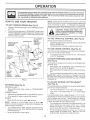
HOW TO USE YOUR TRACTOR
TO SET PARKING
•
BRAKE
Depress clutch/brake
and hotd.
NOTE: Under certain conditions when tractor is standing
idle with the engine running, hot engine exhaust gases may
cause "browning" of grass. To eliminate this possibility,
always stop engine when stopping tractor on grass areas.
(See Fig. 8)
pedal into full "BRAKE" position
CAUTmON: Always stop tractor completely, as described above, before leavo
ing the operator's
position; to empty
grass catcher, etc.
Place parking brake lever in "ENGAGED" position and
release pressure from clutch/brake pedal. Pedal should
remain in "BRAKE" position° Make sure parking brake
will hold vehicle secure..
iGNiTiON
KEY
PARKING BRAKE
"ENGAGED"
POSiTiON
TO USE THROTTLE
ATTACHMENT
CLUTCH
SWITCH
"ENGAGED"
POSITION
TO USE CHOKE
CHOKE
\
ADJUSTMENT
\
KNOB
\
DRIVE"
POSITION
\
°
Slowly release clutch/brake pedal to star! movement.
aMPORTANT: BRING TRACTOR TO A COMPLETE STOP
BEFORE SHIFTING OR CHANGING GEARS. FAILURE
TO DO SO WILL SHORTEN THE USEFUL LiFE OF YOUR
TRANSAXLE
"DaSENGAGED"
POSNTION
TO ADJUST MOWER
(See Fig. 8)
(See Fig, 8)
MOWER BLADES Move attachment
position.
GROUND DRIVE -
clutch switch to "DISENGAGED"
Move throttle control to slow (,_)
o
o
HEIGHT
Turn knob clockwise (f-1) to raise cutting height.
Turn knob counterclockwise (V'_) to lower cutting
height.
The cutting height range is approximately 1-1/4" to 4-1/4".
The heights are measured from the ground to the blade tip
with the engine not running. These heights are approximate and may vary depending upon soil conditions, height
of grass and types ol grass being mowed.
•
The average lawn should be cutto approximately 2-1/2
inches during the cool season and to over 3 inches
during hot months. For healthier and better locking
lawns, mow often and after moderate growth.
o For best cutting performance, grass over 6 inches in
height should oe mowed twice. Make the first cut
relatively high; the second to desired height.
position,
NOTE:
Failure to move throttle control to slow (,_)
position and allowing engine to idle before stopping may
cause engine to "backfire".
o
CUTTING
The cutting height is controlled by turning the height adjustment knob in desired direction.
,
Depress clutch/brake pedal into full "BRAKE" position.
*
Move gearshift lever to neutral (N) position.
ENGINE ,
AND BACKWARD
(See Fig. 8)
FIG. 8
STOPPING
(See Fig, 8)
The direction and speed of movement _scontrolled by the
gearshift lever.
o
Start tractor with clutch/brake pedal depressed and
gearshift lever in neutral (N) position.
Move gearshift and range shift levers to desired posifion.
GEARSHIFT
LEVER
HEIGHT
PEDAL
"BRAKE ....
POSKTJON
CONTROL
TO MOVE FORWARD
"DISENGAGED"
POSITION
LEVER
BRAKE
(See Fig, 8)
Use choke control whenever you are starting a cold engine.
Do not use to start a warm engine.
o To engage choke control, pull knob out. Slowly push
knob in to disengage.
THROTTLE
CONTROL
LEVER
CLUTCH/
CONTROL
Always operate engine at full throttle.
,
Operating engine at less than full throttle reduces the
battery charging rate.
o Full throttle offers the best mower performance.
Turn ignition key to "OFF" position and remove key.
Always remove key when leaving tractor to prevent
unauthorized use.
Never use choke to stop engine.
12
OP
TO ADJUST
GAUGE
WHEELS
RAT
(See Fig. 9)
TO OPERATE
®
®
Adjust mower to desired cutting height.
Lower mower with lift control. Remove rear retainer
spring and clevis pin which secure each gauge wheel.
-
Lower gauge wheels to ground. Raise gauge wheels
slightly to align holes in bracket and gauge wheel bar
and in sert clevis pins. Gauge wheels should be slightly
off the ground.
ON HILLS
CAUTION:
Do not drive up or down
hills with slopes greater than 15 and
do not drive across any slope.
Replace retainer springs into clevis pins.
•
Choose the slowest speed before starting up or down
hills.
o
•
Avoid stopping or changing speed on hills.
tf slowing is necessary, move throttle control lever to
slower position.
If stopping is absolutely necessary, push clutch/brake
pedal quickly to brake position and engage parking
brake°
RETAINER
SPRING
CLEVIS PIN
GAUGE WHEEL
•
GAUGE
WHEEL
Move gearshift lever to I st gear and range shift lever to
low (L) position. Be sure you have allowed room for unit
to roll slightly as you restart movement.
To restart movement, slowly release parking brake and
clutch/brake pedal.
Make all turns slowly.
TO TRANSPORT
o
Raise attachment lift to highest position with attachment lift control,
,,
TO OPERATE
MOWER
When pushing or towing yourtractor, be sure gearshift
lever is in neutral (N) position.
o
Do not push or tow tractor at more than five (5) MPH
NOTE: To protect hood from damage when transporting
your tractor on atruck or atrailer, be sure hood is closed and
secured totractor. Use an appropriate means of tying hood
to tractor (rope, cord, etc.).
(See Figs. 7 and 8)
Your unit is equipped with an operator presence sensing
switch. Any attempt by the operator to leave the seat with
the engine running and the attachment clutch engaged will
shut off the engine.
BEFORE
o
o
Select desired height of cut.
Lower mower with attachment
o
Start mower blades by engaging attachment
control.
o
TO STOP MOWER BLADES - disengage attachment
clutch control.
lift control.
CHECK
clutch
CAUTION: Do not operate the mower
without either the entire grass catcher,
on mowers so equipped, or the discharge guard in place.
®
_
,
STARTING
ENGINE
THE ENGINE
OIL LEVEL
For cold weather operation you should change oil for
easier starting (See "OIL VISCOSITY CHART" in the
Customer Responsibilities section of this manual).
To change engine oil, see the Customer ResponsibiIF
ties section in this manual.
OIL FILL CAP/DIPSTICK
RUNNER
_DISCHARGE
GUARD
FIG. 11
FiG. 10
13
(See Fig. 11)
The engine in your tractor has been shipped from the
factory, already filled with summer weight oil.
Check engine oil with tractor on level ground.
Remove oil fill cap/dipstick and wipe clean, reinsert the
dipstick and push it all the way down into the tube, wait
for a few seconds, remove and read oil level. If,
necessary, add oil until "FULL" mark on dipstick is
reached. Do not overfill.
OPERATmON
ADD GASOUNE
MOWING
Fill fuel tank. Use fresh, clean, regular unleaded
gasoline. (Use of leaded gasoline will increase carbon
and lead oxide deposits and reduce valve life).
iMPORTANT: WHEN OPERATING IN TEMPERATURES
BELOW 32°F(0°C), USE FRESH, CLEAN WINTER GRADE
GASOLINE TO HELP iNSURE GOOD COLD WEATHER
STARTING.
Tire chains cannot be used when the mower housing
is attached to unit.
WARNING:
Experience indicates that alcohol blended
fuels (called gasohol or using ethanol or methanol) can
attract moisture which leads to separation and formation of
acids during storage. Acidic gas can damage the fuel
system of an engine while in storage. To avoid engine
problems, the fue! system should be emptied before storage of 30 days or longer. Drain the gas tank, start the
engine and let it run until the fuel lines and carburetor are
empty. Use fresh fuel next season. See Storage Instructions for additional information.
Never use engine or
carburetor charier products in the fuel tank or permanent
damage may occur.
ENGINE
Mower should be properly leveled for best mowing
performance. See "TO LEVEL MOWER HOUSING" in
the Service and Adjustments section of this manual.
-
Use the runner on the right hand side of mower as a
guide. The blade cuts approximately an inch outside
the runner (See Fig. 10).
The left hand side of mower should be used for trimming.
o
•
If grass is extremely tall, it should be mowed twice to
reduce load and possible fire hazard from dried clippings. Make first cut relatively high; the second to the
desired height.
o
Do not mow grass when it is wet. Wet grass will plug
mower and leave undesirable clumps. Allow grass to
dry before mowing.
o
Always operate engine at full throttle when mowing to
assure better mowing performance and proper discharge of material. Regulate ground speed by selecting a low enough gear to give the mower cutting
performance as well as the quaIity of cut desired.
o
When operating attachments, select a ground speed
that will suit the terrain and give best performance of
the attachment being used.
(See Fig. 8)
pedal aria set parking brake.
Place gearshift lever in neutral (N) position.
®
Move attachment clutch to "DISENGAGED"
position.
Pult choke control out to choke (1",1)
position for cold
engine start For warm engine start do not use choke
control.
o
Drive so that clippings are discharged onto the area
that has been cut. Have the cut area: to the right of the
machine. This wilt result in a more even distribution of
clippings and more uniform cutting.
When mowing large areas, start by turning to the right
so that clippings will discharge away from shrubs,
fences, driveways, etco After one or two rounds, mow
in the opposite direction making left hand turns until
finished (See Fig. 12).
When starting engine for the first time or if engine has run
out of fuel, it will take extra cranking time to move fuel from
the tank to the engine.
Depress clutch!brake
-
o
CAUTION:
Fill to bottom of gas tank
filler neck. Do not overfiJL Wipe off any
spilled oH or fuel Do not store, spill or
use gasomine near an open flame°
TO START
TIPS
Move throttle contro to midway between fast (@_)and
slow (_) positions.
Insert key into ignition and turn key clockwise to"START"
position and release key as soon as eng ne starts. Do
not run starter continuously for more than fifteen
seconds per minute. If engine does not start after
several attempts, move throttle control to fast (,@)
position, wait a few minutes and try again.
•
When engine starts, slowly push choke control in.
Move throttle control to fast (,_)
position.
Allow engine to warm up for a Iew minutes before
engaging drive or attachments.
FIG. !2
NOTE: If at a high altitude tabove 3000 feet) or in cold
temperatures (below 32°F} the carburetor fuel mixture
may need to be adjusted for best engine performance See
"TO ADJUST CARBURETOR'
m _ne Service and Adjustments section of this manual.
14
CUSTOME
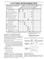
MAINTENANCE
RESPONSiBiLiTiES
SCHEDULE
FILL IN DATES
AS YOU COMPLETE
REGULAR SERVICE
SERVICE
DATES
Check Brake Operation
Check Tire Pressure
T i Check for Loose Fasteners
A
Sharpen!ReplaceMower Blades
C I Lubrication Chart
T I Check Battery,Level/Recharge
O
Clean Battery and Terminals
. Check Transaxle cooling
Adjust Blade Belt(s) Tension
Adjust Motion Drive Belt(s) Tension
Check Engine Oil Level
Change Engine Oil
E!
N
G
J
N
El
Clean Air Filter
Clean Air Screen
Inspect Muffler/Spark Attester
Replace Oil Filter (If equipped)
Clean Engine Cooling Fins
Replace Spark Plug
Replace Air Fitter Paper Cartridge
Replace Fuel Filter
Change more often when operating under a heaw load or in high ambient temperatures.
- Service more often when operating in dirty or dusty conditions.
3 - tf equipped with oil filter, change oil every 50 hours.
4 - Replace blades more often when mowing in sandy soil.
5 - If equipped with adjustable
GENERAL
RECOMMENDATIONS
LUBRICATION
The warranty on this tractor does not cover items that have
been subjected to operator abuse or negligence.
To
receive fu!l value from the warranty, operator must maintain
tractor as instructed in this manual.
(_)TIE
Some adjustments wit! need to be made periodically to
properly maintain your tractor.
system.
CHART
ROD BALL JOINTS
(_) FRONT WHEEL
::::::: :::::
:
FRONT WHEEL Q
All adjustments in the Service and Adjustments section of
this manual should be checked at least once each season.
Once a year you should replace the spark plug, clean
or replace air filter, and check blades and belts for
wear, A new spark plug and clean air filter assure
proper air-fuel mixture and help your engine run better
and last longer.
BEFORE
EACH
SECTOR GEAR
TEETH
ENGINE (_)
USE
o
Check engine oil level.
o
Check brake operation.
,,
Check tire pressure.
TRANSAXLE
FLUID
Check for loose fasteners.
IMPORTANT:
DO NOT OIL OR GREASE THE PIVOT
POINTS
WHICH
HAVE SPECIAL
NYLON BEARINGS.
VISCOUS LUBRICANTS
WILL ATTRACT DUST AND DI RT
THAT
WILL
SHORTEN
THE LIFE
OF THE SELFLUBRICATING
BEARINGS.
tF YOU FEEL THEY MUST
BE LUBRICATED,
USE ONLY
A DRY, POWDERED
GRAPHITE
TYPE LUBRICANT
SPARINGLY.
(_SAE
30 MOTOR OiL API.
(_) GENERAL
PURPOSE
GREASE
(_) REFER TO CUSTOMER
OSPRAY
15
SILICONE
SG
RESPONSIBILITIES
LUBRICANT
"ENGINE"
SECTION
(MOVE BOOTS TO LUBRICATE)
l
CUSTOME
RESPO
LITIES
TRACTOR
•
Always observe safety rules when performing any maintenance.
The blade can be sharpened with a file or on a grinding
wheel. Do not attempt to sharpen while on the mower.
•
To check blade balance, you will need a 5/8" diameter
steel bolt, pin, or acone balancer. (When using acone
balancer, follow the instructions supptied with balancer).
o
Slide blade on to an unthreaded portion of the steel bolt
or pin and hold the bolt or pin parallel with the ground.
If blade is balanced, it should remain in a horizontal
position. If either end of the blade moves downward,
sharpen the heavy end until the blade is balanced.
BRAKE
OPERATION
If unit requires more than six (6) feet stopping distance at
high speed in highest gear, then brake must be adjusted.
(See "TO ADJUST BRAKE" in the Service and Adjustments section of this manual).
TIRES
,,
Maintain proper air pressure in al! tires (See "PRODUCT SPECIFICATIONS" on page 3 of this manual).
o
Keep tires free of gasoline, oil, or insect control chemicals which can harm rubber.
o
Avoid stumps, stones, deep ruts, sharp objects and
other hazards that may cause tire damage.
BLADE
CENTER
CARE
HOLE
518" BOLT
For best results mower blades must be kept sharp.
place bent or damaged blades.
BLADE
NOTE: Do not use a nail for balancing blade. The lobes of
the center hole may appear to be centered, but are not.
REMOVAL
Re-
BLADE
OR PIN
j
(See Fig. 13)
°
Raise mower to highest position to allow access to
blades.
•
Remove hex bolt, lockwasher and flat washer securing
blade.
V-BELTS
o
Install new or resharpened blade with trailing edge up
towards deck as shown;
o
Reassemble hex bolt, lock washer and flat washer in
exact order as shown.
Check V-belts for deterioration and wear after 100 hours
and replace if necessary. The belts are not adjustable.
Replace belts if they begin to slip from wear.
FIG. ! 4
TRANSAXLE
o
Tighten bolt securely (30-35 Ft. Lbs. torque).
IMPORTANT: BLADE BOLT IS GRADE 8 HEATTREATED.
Keep transaxte free from build-up of dirt and chaff which
can restrict cooling.
NOTE: We do not recommend sharpening blade- but if you
do, be sure the blade is balanced.
CHECK TRANSAXLE
(See Fig. 15)
MANDREL
ASSEMBLY
BLADE
COOMNG
•
Block up rear axle securely or use a tractor jack.
o
Remove left rear wheel by removing hub bolts.
o
Remove filler plug from transaxle. Oil level must be
even with plug threads. If necessary, fill with SAE 30
motor oil, API-SG. Replace filler plug.
Reassemble wheel to hub.
o
LOCK WASHER
OIL LEVEL
•
For approximate capacity see "PRODUCT
CATIONS" on page 3 of this manual.
SPECIFI-
TRANSAXLE
FILLER PLUG
o
o
FIG. 13
TO SHARPEN
BLADE
(See Fig° 14)
Care should be taken to keep the blade balanced. An
unbalanced blade will cause excessive vibration and eventual damage to mower and engine.
NG. 15
16
CUSTO
BATTERY
Sl
(See Fig. 16)
NOTE: Although multi-viscosity oils (5W30, !0W30 etc.)
mprove starting in cold weather, these multi-viscosity oils
will result in increased oil consumption when used above
32°F. Check your engine oil level more frequently to avoid
possible engine damage from running low on oil.
Your unit has a battery charging system which is sufficient
for normal use However, periodic charging of the battery
with an automotive charger will extend its life,
-
°
Acid solution level in each battery cell should be even
with bottoms of vent wells. Add only distilled or iron free
water if necessary. Do not overfill.
Change the oil after the first two hours of operation and
every 50 hours thereafter or at least once a year if the
tractor is not used for 50 hours in one year.
Keep battery and terminals clean.
Check the crankcase oil level before starting the engine
and after each eight (8) hours of operation. Tighten oil fill
cap/dipstick securely each time you check the oil level.
Keep battery bolts tight.
Keep vent caps tight and small vent holes in caps open.
o Recharge at 6 amperes for 1 hour.
TO CLEAN BATTERY AND TERMINALS
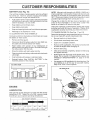
TO CHANGE ENGINE OIL (See Figs. 17 and 18)
-
Determine temperature range expected before oil change.
All oil must meet API service classification SG.
Corrosion and dirt on the battery and terminals can cause
the battery to "leak" power.
Remove terminal guard.
•
Disconnect BLACK battery cable first then RED battery cable and remove battery from tractor.
•
Wash battery with solution of four tablespoons of
baking sodato one gallon of water. Be careful notto get
the soda solution into the cells.
o
Rinse the battery with plain water and dry.
•
Clean terminals and battery cable ends with wire brush
until bright.
o
Coat terminals with grease or petroleum jelly.
Reinstall battery (See "INSTALL BATTERY"
Assembly section of this manual).
j
o
Be sure tractor is on level surface.
•
-
Oil wil drain more freely when warm.
Catch oi! in a suitable container,
®
Remove oil fill cap/dipstick. Be careful not to allow dirt
to enter the engine when changing oil.
•
Remove drain plug.
°
After oil has drained corn pletely, replace oil drain plug
and tighten securely.
Refill engine with oil through oil fill dipstick tube. Pour
slowly. Do not overfill. For approximate capacity see
"PRODUCT SPECIFICATIONS"
on page 3 of this
manual.
in the
Use gauge on oil fill cap/dipstick for checking level, Be
sure dipstick is in all the way for accurate reading.
Keep oil at "FULL" line on dipstick.
CUT AWAY VIEW
L__q::::C:=:ZT__I
LITIES
VENTvENT
CAP
OIL DRAIN PLUG
WELL
\
BATTERY
CELL ACID
LEVEL
\
\
OIL FILL
CAP/DIPSTICK
FiG. 16
ENGmNE
LUBRiCATiON
Only use high quality detergent oi rated with API service
classification SG. Select the oil's SAE viscosity grade
according to your expected operating temperature.
SAE VISCOSITY
GRADES
FIG. 18
:)o
-20 <
qEMPERATURE
30 °
- 10°
RANGE
60 °
0'
AN3 r CiPATED
10'
BEFORE
80 _
20'
NEXT
30'
40 °
OIL CHANGE
FIG, 17
17
CUSTOME
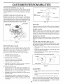
CLEAN
AmR SCREEN
PONSI
ILITIES
(See Fig. 19)
WING NUT
Air screen must be kept free of dirt and chaff to prevent
engine damage from overheating. Clean with a wire brush
or compressed air to remove dirt and stubborn dried gum
fibers.
CARTRIDGE
PLATE
_S_'_
FOAM
ENGINE
COOLING
SEAL
_'_J JJ
FINS (See Fig, 19)
Remove any dust, dirt or oil from engine cooling fins to
prevent engine damage from overheating. Engine blower
housing must be removed. Remove side panels and hood
(See "TO REMOVE HOOD AND GRILL ASSEMBLY" in the
Service and Adjustments section of this manual).
FIG. 20
A_R SCREEN
COOLING FINS
(BOTH S_DES)
MUFFLER
inspect and replace corroded muffler and spark arrester (if
equipped) as it could create a fire hazard and/or damage.
\
SPARK
PLUGS
Replace spark plugs at the beginning of each mowing
season or after every 100 hours of operation, whichever
comes first. Spark plug type and gap setting are shown in
"PRODUCT SPECIFICATIONS" on page 3 of this manual.
\
ENGINE
OIL FILTER
Replace the engine oil filer every season or every other oil
change if the tractor is used more than !00 hours in one
year.
IN-LINE
FIG. 19
AIR FmLTER (See Fig. 20)
Your engine will not run properly using a dirty air filter.
Clean the foam pre-cleaner element after every 25 hours of
operation or every season. Service paper cartridge every
100 hours or every season, whichever occurs first.
Service air cleaner more often under dusty conditions.
,,
FUEL FILTER
(See Fig. 21)
The fue! filter should be replaced once each season. If fuel
filter becomes clogged, obstructing fuel flow to carburetor,
replacement is required.
o With engine cool, remove filter and plug fuel line
sections.
•
Place new fuel filter in position in fuel line with arrow
pointing towards carburetor.
o
Be sure there are no fuel line leaks and clamps are
property positioned.
Immediately wipe up any spilled gasoline.
Remove wing nut and cover.
•
Remove seal and cartridge plate.
TO SERVICE PRE-CLEANER
,,
Slide foam pre-cteaner off cartridge.
o
•
Wash it in liquid detergent and water.
Squeeze it dry in a clean cloth.
CLAMP
FUEL FILTER
,
Saturate it in engine oil. Wrap it in clean, absorbent
cloth and squeeze to remove excess oil.
TO SERVICE CARTRIDGE
,
FMGo21
Gently tap the flat side of the paper cartridge to dislodge dirt. Do not wash the paper cartridge or use
pressurized air, as this will damage the cartridge.
Replace a dirty, bent, or damaged cartridge.
Reinstall the pre-cleaner
paper cartridge.
CLEANING
(cleaned and oiled) over the
®
Reassemble air cleaner, cartridge plate, and seal.
,,
Install the air cleaner cover and wing nut. Tighten wing
nut 1/2turn to 1 fullturn after nut contactscover. Do not
overtighten.
18
°
Clean engine, battery, seat, finish, etc. of all foreign
matter.
•
Keep finished surfaces and wheels free of all gasoline,
oil, etc.
•
Protect painted surfaces with automotive type wax.
We do not recommend using a garden hose to clean your
tractor unless the electrical system, muffler, air filter and
carburetor are covered to keep water out. Water in engine
can result in a shortened engine life.
ADJU
SERVICE
CAUTION:
BEFORE PERFORMING
ANY SERVICE OR ADJUSTMENTS:
Depress dutch/brake
pedal fully and set parking brake,
Place gearshift lever in neutral (N) position=
Place attachment ctutch in "DISENGAGED"
position.
Turn ignition key "OFF" and remove key.
Make sure the blades and all moving parts have completely stopped,
Disconnect spark plug wire from spark plug and place wire where it cannot come in contact
with plug.
o
•
o
-
TRACTOR
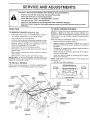
TO REMOVE
TO LEVEL MOWER
MOWER
HOUSING
Adjust the mower while tractor is parked on level ground or
driveway.
Make sure tires are properly inflated (See
"PRODUCT SPECIFICATIONS" on page 3 of this manual)
If tires are over or undednflated, you will not properly adjust
your mower.
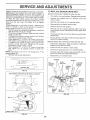
SIDE-TO-SIDE ADJUSTMENT (See Figs. 22 and 23)
Raise mower to its highest position.
•
Measure height from bottom of deck cud to ground
level at front corners of mower. Distance "A" should be
the same.
°
tf distance "A" needs to be changed, make adjustment
on one side of mower only,
•
Raise one side of mower by tightening lift link adjustment nut on that side.
(See Fig, 22)
•
•
•
•
Place attachment clutch in "DISENGAGED" position.
Turn height adjustment knob to !owest setting.
Lower mower to its lowest position.
Remove retainer spnng holding anti-swaybar to chassis bracket and disengage antioswaybar from bracket.
•
Remove retainer springs from suspension arms at
deck and disengage arms from deck.
,
Raise attachment lift to its highest position.
•
Remove two retainer springs from each front link and
remove links.
•
Slide mower forward and remove belt from electric
clutch pulley.
,
Slide mower out from under right side of tractor.
IMPORTANT: IF AN ATTACHMENT OTHER THAN THE
MOWER DECK IS TO BE MOUNTED ON THE TRACTOR,
REMOVE THE FRONT LINKS.
TO iNSTALL
NTS
Lower one side of mower by loosening lift link adjustment nut on that side.
NOTE: Each half turn of adjustment nut will change deck
level about 1/4".
•
MOWER
Recheck level after adjusting.
Follow procedure described in "INSTALL MOWER AND
DRIVE BELT" in the Assembly section of this manual,
FRONT
SUSPENSION
BRACKET
ADJUSTMENT
SUSPENSION
ARMS
NUTS
LIFT
LINKS
\
\
\
FRONT MOWER
BRACKET
ELECTRIC
CLUTCH
PULLEY
CHASSIS
BRACKET
FRONT
SUSPENSION
BRACKET
RETAINER
SPRINGS
/
RETAINER
SPRING
MOWER
BRACKET
/
/
ANTFSWAY
BAR
\
\
FIG. 22
19
SERVICE
AND AOJ
STMENTS
TO REPLACE
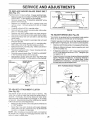
FRONT-TO-BACK ADJUSTMENT (See Figs. 24 and 25) iMPORTANT: DECK MUST BE LEVEL SIDE-TO-SIDE. IF
THE FOLLOWING FRONT-TO-BACK ADJUSTMENT IS
NECESSARY, BE SURE TO ADJUST BOTH FRONT LINKS
EQUALLY SO MOWER WILL STAY LEVEL SIDE-TO°SIDE.
To obtain the best cutting results, the mower housing
should be adjusted so the front is approximately 1/8" to 1/2"
lower than the rear when the mower is in its highest
position.
Check adjustment on right side of tractor. Measure distance ',F" directly in front of and behind the mandrel at
bottom edge of mower housing as shown.
,
Before making any necessary adjustments, checkthat
both front links are equal in length:
•
If links are not equal in length, adjust one link to same
length as other link.
To lower front of mower housing, loosen nut"G" on both
front links an equal number of turns.
® When distance "F" is 1/8" to 1/2" lower at front than
rear, tighten nut"H" against trunnion on both front links.
.
To raise front of mower housing, loosen nut "H" from
trunnion on both front links. Tighten nut "G" on both
front links an equal number of turns.
When distance "F" is 1/8" to 1/2" lower at front than
rear, tighten nut "H" against trunnion on both front
links.
NOTE: Each full turn of nut "G" will change dim. "F" by
approximately 3/8"o
•
Recheck side-to-side adjustment.
MOWER
DRIVE. BELT
MOWER DRIVE BELT REMOVAL (See Fig. 26) o
•
•
Park tractor on a level surface. Engage parking brake.
Remove four screws from L.H. mandrel cover and
remove cover.
Rol! belt over the top of L.H. mandrel pulley.
o
Remove belt from electric dutch pulley.
•
Remove belt from idler pulleys.
o
Remove any dirt or grass clippings which may have
accumulated around mandrels and entire upper deck
surface.
o
Check primary idler arm and two idlers to see that they
rotate freely.
o
Be sure spring is securely hooked to primary idler arm
and bolt in mower housing.
MOWER DRIVE BELT INSTALLATION (See Fig. 26) •
Install belt in both idlers. Make sure belt is in both belt
keepers at the idlers as shown.
o
Install new belt onto electric clutch pulley.
-
Roll belt into upper groove of L.H. mandrel pulley.
o
Carefully check belt routing making sure belt is in the
grooves correctly and inside belt keepers.
Reassemble L.H. mandrel cover.
SCREWS
"F" _
SPRING
_ "F"
G ROU N_DL_NE
/Z7Z?77-77777777_/
7_;:_:(
:7 iTZ777-_T77*777777-T/7
FIG. 24
i:iii!_
BOTH FRONT LINKS SHOULD BE EQUAL IN LENGTH
BOLT IN
HOUSING
FIG, 26
NUT "H"
FRONT LINKS
FiG. 25
2O
SE
TO
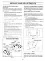
REPLACE
MOWER
CE
BLADE
ADJUSTMENTS
DRIVE
BELT
(See Fig. 27)
Park the tractor on level surface. Engage parking brake,
Remove mowerdrive belt (See'qO REPLACE MOWER
DRIVE BELT" in this section of this manual),
o Remove mower (See "TO REMOVE MOWER" in this
section of this manual).
o
Remove four screws from R.H. mandrel cover and
remove cover. Unhook spring from bolt on mower
housing.
o
Carefully roll belt off R.H. mandrel pulley.
Remove belt from center mandrel pulley, idler pulley,
and L.H. mandrel pulley.
o
Remove any dirt or grass which may have accumulated around mandrels and entire upper deck surface.
•
Check secondary idler arm and idler to see that they
rotate freely.
Be sure spring is hooked in secondary idler arm and
sway-bar bracket.
o
Install new belt in lower groove of L.H. mandrel pulley,
idler pulley, and center mandrel pulley as shown.
•
Roll belt over R.H. mandrel pulley. Make sure belt is in
all grooves properly.
Reconnect spring to bolt in mower housing and reinstall R.H. mandrel cover.
Reinstall mower to tractor (See"TO INSTALL MOWER"
in the Assembly section of this manual).
o Reassemble mower drive belt (See "TO REPLACE
MOWER DRIVE BELT" in this section of this manual).
NYLON LOCKNUT
(3)
BRAKE
FIG, 28
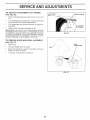
TO ADJUST
BRAKE
(See Fig. 29)
Your tractor is equipped with an adjustable brake system
which is mounted on the left side of the transaxie.
If tractor requires more than six (6)feet stopping distance
at high speed in highest gear, then brake must be adjusted.
CENTER
MANDREL
•
Depress clutch/brake pedal and engage parking brake.
•
Measure distance between brake operating arm and
nut "A" on brake rod.
-
If distance is other than 1-3/4", loosen jam nut and turn
nut 'A until distance becomes 1-3/4". Retighten jam
nut against nut "A".
•
Road test tractor for proper stopping distance as stated
above. Readjust if necessary. If stopping distance is
still greater than six (6) feet in highest gear, further
maintenance is necessary. Contact your nearest authorized service center/department.
WiTH PARKING BRAKE "ENGAGE"
COVER
/
iDLER ARM
tSCREW
,°
\
NUT "A"
SPRING j
SWAY-BAR
BRACKET
OPERATING
ARM
iDLER
PULLEY
NUT
FIG. 27
TO ADJUST ATTACHMENT
(See Fig. 28)
CLUTCH
The electric clutch should provioe years of service. The
_tutch has a bulk-in brake that stops the pulley within 5
3econds. Eventually, the internal brake will wear which
may cause the mower blades to not engage, or, to not stop
as required. Adjustments should be made byyour nearest
adthorized service center/department.
°
Make sure atta chment clutch and ignition switches are
in "OFF" position.
°
Adjust the three nylon Iocknuts until space between
clutch plate and rotor measures .0t2" at all three slot
locations cut inside of brake plate.
NOTE: After installing a new electric clutch, run tractor at
full throttle and engage and disengage electric clutch 10
cycles to wear unclutch plate
PLATE
\
FiG, 29
21
SERVICE AND ADJUSTMENTS
TO REPLACE
(See Fig, 30}
MOTION
DRmVE BELT
TO ADJUST
Raise hood and disconnect
tery cable.
o
Set parking brake (to get belt slack).
,
Remove mower drive belt from electric clutch pulley
only (See "TO REPLACE MOWER DRIVE BELT" in
this section of this manual).
FRONT WHEEL
BLACK (grounding) bat-
TOE-IN
ADJUSTMENT
TO CHECK TOE-IN (Se e Fig. 31) •
•
Roll belt off clutching idler pulleys, then off engine
pulley and front V-idler pulley.
•
Pull belt out of all belt keepers.
BELT INSTALLATION Place V part of belt into grooves on engine pulley and
front V-idler, making sure to route belt inside of belt
keepers.
Position front wheeis straight ahead.
Measure distance between wheels at front and rear of
tires (dimensions "A" and "B").
Front dimension "A" should be 1/8" to 1/4" less than
rear dimension "B".
TO ADJUST TOE-IN (See Figs. 31 and 32) -
Put belt coming from V-idler above midspan belt keeper,
then onto clutching idler pulleys as shown.
Make sure "V" part of belt engages "V" idler°
•
Loosen jam nuts at adjustment sleeves on tie rod.
•
Adjusttieroduntildimenslon"A"isl/8"tol/4"lessthan
dimension "B".
o
Tighten jam nuts securely.
Place belt around transaxle pulley, beginning at top.
"V" part of belt should engage transaxle pulley.
-
ALIGNMENT
Front wheel toe-in is required for proper steering operation.
Toe-in was set at the factory and adjustment should not be
necessary. If parts in the front axle or steering mechanism
have been replaced or damaged, check toe-in and adjust
if necessary.
Roll motion drive belt Off transaxle pulley.
,
WHEEL
If steering wheel crossbars are not horizontal (left to right)
when wheels are positioned straightforward, remove steering wheel and reassemble per instructions in the Assembly
section of this manual.
Park the tractor on level surface. Engage parking brake.
For ease of service there is a belt installation guide decal on
bottom of left footrest. It is not necessary to remove mower.
BELT REMOVAL•
STEERING
B
Place long lower section of belt through loop in midspan
belt keeper.
Check to be sure belt is on proper side of all belt
keepers.
o
_
Reinstall mower drive belt onto electric clutch pulley.
FRONT
OF TRACTOR
_
•
Release parking brake.
IMPORTANT: CHECK BRAKE ADJUSTMENT.
TRACTOR VoBELT DRIVE SCHEMATaC
VIEWED FROM L;H. SlOE OF TRACTOR
CLUTCHBNG
_DLER
FIG. 31
ADJUSTMENT
BELT
TIE ROD
CLUTCHING
FLAT gDLER
ENGINE
PULLEY
SLEEVES
ABOVE
VqDLER
JAM NUTS
BELT
TWISTS
/\
BELT
KEEPER
PULLEY
TRANSAXLE
PULLEY
FIGo 32
FRONT WHEEL
CAMBER
The front whee camber is not adjustable on your tractor. If
damage has occurred to affect the front wheel camber,
contact your nearest authorized service center/department.
AS VIEWED FROM BOTTOM
RG. 30
22
SE
TO REMOVE
WHEEL
CE AN
A
USTMENTS
FOR REPAIRS
POSTVE
I NE
FRONT WHEEL (See Fig. 33) =
•
Block up axle securely.
o
Remove axle cover, retaining ring and washers to allow
wheel removal.
(+)
Repair tire and reassemble.
o
Replace washers and snap retaining Hng securely in
axle groove.
o
Replace axle cover.
(-)
FiG. 34
WASHERS
RETAINING
PANEL
RING \
AXLE
\
covE_
\
° °
FiG. 33
FiG. 35
REAR WHEEL o
Block rear axle securely.
•
Remove five (5) hub bolts to allow wheel removal.
TO REPLACE
Repair tire and reassemble.
bolts securely.
-
Raise hood.
-
Pull bulb holder out of the hole in the backside of the
grill.
o
Replace bulb in holder and push bulb holder securely
back into the hole in the backside of the grill.
Close hood.
Replace and tighten hub
TO START ENGINE WITH A WEAK
See Figs. 34 and 35)
BATTERY
-
CAUTION:
Lead-acid batteries gener=
ate e×plosive gases. Keep sparks, flame
and smoking materials away from batteries.
Always wear eye protection
when around batteries.
INTERLOCKS
o
TO REPLACE
FUSE
Replace with 30 amp automotive-type plug-in fuse,
fuse holder is located behind the dash,
CABLES -
Connect each end of the RED cable to the POSITIVE
(+) terminal of each battery, taking care not to short
against chassis,
Connect one end of the BLACK cable to the NEGATIVE (-) terminal of fully charged battery.
Connect the other end of the BLACK cable to a panel
bolt on the left side of the tractor, away from fuel tank
and battery.
TO REMOVE CABLES, REVERSE ORDER -
o
AND RELAYS
Check wiring. See electrical wiring diagram _nRepair
Parts section of this manual.
IMPORTANT:
YOUR TRACTOR iS EQUIPPED WITH A 12
VOLT NEGATIVE
GROUNDED
SYSTEM.
THE OTHER
VEHICLE
MUST
ALSO
BE A 12 VOLT
NEGATIVE
GROUNDED
SYSTEM.
DO NOT USE YOUR TRACTOR
BATTERY TO START OTHER VEHICLES.
o
BULB
Loose or damaged wiring may cause your tractor to run
poorly, stop running, or prevent it from starting.
If your battery is too weak to start the engine, it should be
recharged.
If "jumper
cables" are used for emergency
starting, follow this procedure:
TO ATTACH JUMPER
HEADLIGHT
BLACK cable first from chassis and fully charged
battery.
RED cable last from both batteries.
23
The
E
CE AND ADJUSTMENTS
TO ADJUST ATTACHMENT
(See Fig. 36)
LiFT SPIRING
ADJUSTMENT
BOLT
•
While holding spring bushing with wrench, loosen jam
nut.
•
Turn adjustment bolt clockwise to extend spring and
reduce lift effort (for heavier attachments).
,,
Turn adjustment
tachments.
Retighten
bolt counterclockwise
jam nut against
spring
HOOD
AND
®
JAM NUT
bushing.
GRILL
BUSHING
for lighter at-
IMPORTANT:
DO NOT ADJUST FOR MAXIMUM SPRING
TENSION WHEN USING LIGHT ATTACHMENTS
SUCH
AS A MOWER.
ADJUST LIFT LEVER SPRING TO AID IN
LIFTING ATTACHMENT.
DO NOT OVERPOWER
SPRING.
WHEN REMOVING
ATTACHMENT,
ALWAYS ADJUST
SPRING TENSION TO ITS LOWEST POSITION.
TO REMOVE
SPRING
o
ATTACHMENT
UFT SPRMNG
®
FiG. 36
ASSEMBLY
(See Fig. 37)
•
Raise hood.
/
/
WIRE
CONNECTION
,/
,,
Unsnap headlight wire connector.
•
Stand in front of tractor. Grasp hood at sides, tilt toward
engine and lift off of tractor°
o
To replace, reverse above procedure.
/
HOOD
FNG.37
24
SERVICE
A
ADJU
ACCELERATION
ENGINE
•
TO ADJUST
THROTTLE
(See Fig. 38 & 39)
CONTROL
CABLE
The throttle control has been preset at the factory and
adjustment should not be necessary. Check adjustment as
described below before loosening cable. If adjustment is
necessary, proceed as follows:
Check that speed control lever is against stop screw. If
it is not, loosen casing clamp screw and pull throttle
cable until lever is against screw. Tighten clamp screw
securely.
TO ADJUST
CARBURETOR
(See
Fig. 40)
The carburetor has been present at the factory and adjustment should not be necessary. However, minor adjustment
may be required to compensate for differences in fuel.
temperature, altitude or load. If the carburetor does not
need adjustment, proceed as follows:
Move throttle control lever from slow (-_)
to fast (,@)
position. If engine hesitates or dies, turn idle mixture
screw out (counterclockwise)
I/8 turn. Repeat test and
continue to adjust, if necessary,
until engine accelerates smoothly.
CASING
CLAMP \
in general, turning the adjusting needles in (clockwise)
decreases the supply of fuel to the engine giving a leaner
fuel/air mixture. Turning the adjusting needles out (counterclockwise) increases the supply of fuel to the engnne
giving a richer fuel/air mixture.
IMPORTANT:
DAMAGE TO THE NEEDLES AND THE
SEATS IN CARBURETOR MAY RESULT IF SCREW IS
TURNED IN TOO TIGHT.
PRELIMINARY
STOP SCREW
/
j"
Be sure you have a clean air filter, and the throttle
control cable is adjusted properly (see above).
o
With engine off turn idle fuel adjusting needle in (clockw_se) closing it finger tight and then turn out (counterclockwise) 1-1/4 turns.
FIG. 38
STOP
Turn main fuel adjusting needle in (clockwise) closing
finger tight and then turn out (counterclockwise) 1 turn.
FINAL SETTING o
Start engine and allow to warm for five minutes. Make
final adjustments with engine running and shift/motion
control lever in neutral (N) position.
•
With throttle control lever in fast ( ,1_ ) position, turn
main fuel adjusting needle in (clockwise) until engine
begins to die then turn out (counterclockwise) until
engine runs rough. Turn needle to a point midway
between those two positions
•
SPEED CONTROL
LEVER
/li;?1
SETTING -
*
TEST -
High speed stop is factory adjusted. Do not adjust-damage
may result.
IMPORTANT:
NEVER TAMPER
WITH THE ENGINE
GOVERNOR
WHICH IS FACTORY
SET FOR PROPER
ENGINE SPEED. OVERSPEEDING
THE ENGINE ABOVE
THE
FACTORY
HIGH
SPEED
SETTING
CAN BE
DANGEROUS
IFYOUTHINKTHEENGINE-GOVERNED
HIGH SPEED NEEDS ADJUSTING.
CONTACT
YOUR
NEAREST
AUTHORIZED
SERVICE
CENTER!
DEPARTMENT.
WHICH HAS PROPER EQUIPMENT
AND
EXPERIENCE
TO
MAKE
ANY
NECESSARY
ADJUSTMENTS.
With engine not running, move throttle control lever to
fast ('¢ep)position.
o
ENTS
SPEED
CONTROL
LEVER
FroG.39
IDLE SPEED
ADJUSTING
SCREW -o
Idle s_p_eedsetting - With throttle control lever in slow
(,_!)
position, engine should idle at 1400 RPM. If
engine idles too slow or fast turn idle speed adjusting
screw in or out until correct idle is attained.
Idle fuel needte setting - With throttle control lever in
slow (_)
position, _urn idle fuel adjusting needle in
(clockwise) until engine begins to die and then turn out
(coun[erclockwise) until engine runs rough° Turn needle
to a point midway between those two positions.
Recheck idle speed, Readjust if necessary.
25
FIG, 40
STORAGE
Immediately prepare your tractor for storage at the end of
the season or if the tractor will not be used for 30 days or
more.
ENGINE
FUEL SYSTEM
iMPORTANT:
IT IS IMPORTANT
TO PREVENT
GUM
DEPOSITS
FROM FORMING
IN ESSENTIAL
FUEL
SYSTEM PARTS SUCH AS CARBURETOR
FUEL FILTER,
FUEL H©SE. OR TANK DURING
STORAGE.
ALSO,
EXPERIENCE
INDICATES
THAT ALCOHOL
BLENDED
FUELS ICALLED
GASOHOL
OR USING ETHANOL
OR
METHANOL)
CAN ATTRACT MOISTURE
WHICH LEADS
TO SEPARATION
AND FORMATION
OF ACIDS DURING
STORAGE.
ACIDIC GAS CAN DAMAGE
THE FUEL
SYSTEM OF AN ENGINE WHILE IN STORAGE.
TRACTOR
Remove mower from tractor for winter storage
When
mower is to be stored for a period of time. clean it thoroughly, remove all dirt, grease, leaves, etc. Store in a
clean, dry area.
-
Clean entire tractor (See "CLEANING" in the Customer
Responsibilities section of this manual).
o
Inspect and replace belts, if necessary (See belt replacement instructions in the Service and Adjustments
section of this manual).
Q
e
Be sure that all nuts, bolts and screws are securely
fastened. Inspect moving parts for damage, breakage
and wear. Replace if necessary.
o
Touch up all rusted or chipped paint surfaces: sand
lightly before painting.
NOTE: Fuel stabilizer is an acceptable alternative in
minimizing the formation of fuel gum deposits during storage. Add stabilizer to gasoline in fuel tank or storage
container. Always follow the mix ratio found on stabilizer
container. Run engine at least 10 minutes after adding
stabilizer to allow the stabilizer to reach the carburetor. Do
not drain the gas tank and carburetor if using fuel stabilizer.
ENGINE
Fully charge the battery for storage.
o
After a period of time in storage, battery may require
recharging.
-
To help prevent corrosion and power leakage during
long periods of storage, battery cables should be
disconnected and battery cleaned tho roughly (see "TO
CLEAN BATTERY AND TERMINALS" in the Customer Responsibilities section of this manua ).
-
CYUNDERS
After cleaning, leave cables disconnected and place
cables where they cannot come Jncontact with battery
terminals.
®
Be sure battery drain tube is securely attached.
o
If battery is removed from tractor for storage, do not
store battery directly on concrete or damp surfaces.
OIL
Drain oil (with engine warm) and replace with clean engtne
oil. (See "ENGINE" in the Customer Responsibilities
section of this manuab.
BATTERY
-
Start the engine and tet it run until the fuel lines and
carburetor are empty.
Never use engine or carburetor cleaner products in the
fuel tank or permanent damage may occur.
Use fresh fuel next season.
Lubricate as shown in the Customer Responsibilities
section of this manual.
o
Drain the fuel tank.
o
Remove spark plug(s).
,
Pour one ounce of oil through spark plug hole(s) into
cylinder(s).
•
Turn ignition key to"START" position for a few seconds
to distribute oil.
o
Replace with new spark plug(s).
OTHER
o
Do not store gasoline from one season to another.
Replace your gasoline can if your can starts to rust.
Rust and/or dirt in your gasoline will cause problems
o
o
If possible, store your tractor indoors and cover it to
give protection from dust and dirt.
Cover your tractor with a suitable protective cover that
does not retain moisture Do not use plastic. Plastic
cannot breathe which allows condensation to form and
will cause your tractor to rust.
iMPORTANT: NEVER COVER TRACTOR WHILE ENGINE
AND EXHAUST AREAS ARE STILL WARM.
26
SE
ICE
27
OTES
T iOUBLESHOOTING
TS
m
PROBLEM
CAUSE
Wiml not start
Hard
to start
Engine
Engine
start
will not turn over
clicks
but will not
Loss of power
1.
Out of fuel,
2.
3.
4.
5.
6.
7.
Engine not "CHOKED"
Engine flooded.
Bad spark plug.
Dirty air filter.
Dirty fue! filter.
Water in fuel.
1.
Fill fuel tank.
properly.
2,
3.
4.
5.
6.
7.
8.
9.
10.
Loose or damaged wiring.
Carburetor out of adjustment.
Engine valves out of adjustment,
8,
9.
10.
See "TO START ENGINE" in Operation section.
Wait several minutes before attempting to start.
Replace spark plug.
Clean/replace air filter,
Replace fuel filter.
Drain fuel tank and carburetor, refill tank with fresh
gasoline and replace fuel filter.
Check all wiring.
Contact an authorized service center/department.
Contact an authorized service center/department.
1.
2.
3.
4.
5.
6.
7.
8,
Dirty air filter.
Bad spark plug.
Weak or dead battery.
Dirty fue! filter.
Stale or dirty fuel.
Loose or damaged wiring.
Carburetor out of adjustment.
Engine valves out of adjustment.
1.
2.
3.
4.
5.
6.
7.
8.
Clean/replace air filter,
Replace spark plug.
Recharge or replace battery.
Replace fuel filter.
Drain fuel tank and refill with fresh gasoline.
Check al! wiring.
Contact an authorized service center/department.
Contact an authorized service center/department.
1.
2.
3.
4.
Clutch/brake pedal not depressed.
Attachment clutch is engaged.
Weak or dead battery.
Blown fuse.
1.
2,
Depress clutch/brake pedal.
Disengage attachment clutch.
5.
6.
7,
8.
9.
Corroded battery terminals.
Loose or damaged wiring.
Faulty ignition switch.
Faul[y solenoid or starter.
Faulty operator presence switch(es).
3.
4.
5.
6.
7.
8.
Recharge or replace battery.
Replace fuse.
Clean battery terminals.
Check all wiring.
ChecWreplace ignition switch.
ChecWreplace solenoid orstarter,
9.
Contact an authorized
1,
2.
3.
4.
Weak or dead battery.
Corroded battery terminals.
Loose or damaged wiring.
Faulty solenoid or starter.
1.
2.
3.
4.
Recharge or replace battery.
Clean battery terminals,
Check aft wiring.
Check/replace solenoid or starter.
1.
2.
3.
4,
5.
6.
7.
8.
9.
Cutting too much grass/too fast.
Throttle in "CHOKE" position,
Build-up of grass, leaves and trash under mower,
Dirty air filter.
Low oil level/dirty oil.
Faulty spark plug.
Dirty fuel filter.
Stale or dirty fuel.
Water in fuel.
!,
2.
3.
4,
5.
6.
7.
8,
9.
Set in "Higher Cut" position/reduce speed.
Adjust throttle control.
Clean underside of mower housing.
Clean/replace air filter.
Check oil level/change oil.
Clean and regap or change spark plug.
Replace fuel filter.
Drain fuel tank and refill with fresh gasoline.
Drain fuel tank and carburetor, refill tank with fresh
gasoline and replace fuel filter.
Connect and tighten spark plug wire.
Clean engine air screen/fins.
Clean/replace muffler,
Check all wiring.
Contact an authorized service center/department.
Contact an authorized service center/department.
10.
!1,
12.
13.
14.
15.
Excessive
vibration
CORRECTION
1.
2.
3,
Spark plug wire loose.
Dirty engine air screen/fins,
Dirty/clogged muffler.
Loose or damaged wiring.
Carburetor out of adjustment,
Engine valves out of adjustment,
10.
11.
12.
3.
!4.
15.
Worn, bent or loose blade.
Bent blade mandrel.
Loose/damaged part(s).
1.
2.
3.
28
service center/department.
Replace blade. Tighten blade bolt.
Replace blade mandrel.
Tighten loose part(s). Replace damaged
parts.
TROU
LESH
OTI
POINTS
CORRECTION
PROBLEM
CAUSE
Engine continues to run
when operator leaves seat
with attachment clutch
1
Faulty operator-safety
1.
2.
1,
Check wiring, switches and connections.
If net
corrected, contact an authorized service center/
department.
Worn. bent or loose blade.
Mower deck not level.
1.
2.
Replace blade. Tighten blade bolt.
Level mower deck.
3.
4.
Buildup of grass, leaves, and trash under mower.
Bent blade mandrel.
5.
Clogged mower deck vent holes from buildup of
grass, leaves, and trash around mandrels.
3,
4.
5.
Clean unaerside Of mower housing.
Replace blade mandrel.
Clean around mandrels to open vent holes.
presence control system,
engaged
Poorcut-uneven
Mower blades wiii not
rotate
Poor grass discharge
1.
Obstruction
1
Remove obstruction,
2.
3.
4.
Worn/damaged mower drive belt.
Frozen idler pulley.
Frozen blade _nandrel,
2,
3,
4
Replace mower drive belt.
Replace idler pulley.
Replace blade mandrel.
Engine speed too slow.
Travel speed too fast.
Wet grass,
Mower deck not level.
Low/uneven tire air pressure.
Worn, bent or loose blade,
Buildup of grass, leaves and trash under mower.
Mower drive belt worn.
Blades improperly installed.
Improper bladeS used
Clogged mower deck vent holes from buildup of
grass. Eeaves, and trash around mandrels.
1
2,
3,
4,
Place throttle control in "FAST" position,
Shift to slower speed,
Allow grass to dry before mowing.
Level mower deck,
1.
2.
3.
4.
5.
6.
7.
8,
9.
t0,
11.
ir clutch mechanism.
5
6.
7
8
9
10.
11
Check tires for proper air pressure.
Replace/sharpen blade. Tighten blade bolt.
Clean underside of mower housing.
Replace mower drive belt,
Reinstall blades sharp edge down.
Replace with blades listed in this manual.
Clean around mandrels to open yen1 holes.
Headlight(s) not working
(if so equipped)
1.
2.
3.
4.
5,
Switch is "OFF",
Bulb(s) burned out.
Faulty light switch.
Loose or damaged wiring.
Blown fuse.
1.
2,
3.
4.
5.
Turn switch "ON".
Replace bulb(s),
Check/replace light switch.
Check wiring and connections.
Replace fuse.
Battery will not charge
1.
2.
3.
4.
Bad battery cell(s).
Poor cable connections.
Faulty regulator (if so equipped).
Faulty alternator.
1.
2.
Replace battery.
Check/clean all connections.
3.
4.
Replace regulator.
Replace alternator.
1
Engine throttle control not set at "SLOW"
position for 30 seconds before stopping engine,
1,
Move throttle control to "SLOW" position and allow
to idle for 30 seconds before stopping engine.
Engine "backfires"
when turning engine
"OFF"
29
18 HP 44" TRACTOR
= MODEL NUMBER
917.257720
SCHEMATIC
RED
BLACK
BATTE RY
FUSE 30 AMP.
\
RED
RED
AMMETER
WHITE
[c---;
,_
_
.........
I
; ("_) I _
F
,,
RED
WH,TE
hi _@_
L__
CLUTCH / BRAKE
(PEDAL UP)
:
STARTER
BLAO,.
SOLENO,D
ELECTRIC CLUTCH
t
REDo--_a a X a /--O_L!I
3LACK
_D
SEAT SWITCH
(NOT OCCUPIED)
t
1
I
I
q-
I--
L
__
GROUNDING
CONNECTOR
I!
BLACK
(_
IGNITION
UNIT
SPARK
9_----_
_
PLUGS
_
D
CHARGING SYSTEM OUTPUT
15 AMP DC @ 3600 RPM
I
RED
28 VOLTS AC @ 3600 RPM
,REGULATOR
DISCONNECTED
ORANGE
_D
HEADLIGHT
_i_._
SWITCH (OFF)
BROWN
___
_
BLACK
HEADLIGHTS
•
O
NON-REMOVABLE
CONN ECTtONS
IGNITION SWITCH
CIRCUIT
_--
M+G
G FC
If0
E H_B
D IUA
REMOVABLE
CONN ECTIONS
WIRING iNSULATED CLIPS
NOTE: IF WIRING INSULATED
CLIPS WERE REMOVED FOR
SERVICING OF UNIT, THEY
SHOULD BE REPLACED TO
PROPERLY SECURE YOUR WIRING
30
PTO SWITCH
POSITION
l
CIRCUIT
4
OFF
!
ON
JC+F,B=E,A+D
C _ G
REPAIR PARTS
18 HP 44" TRACTOR
- - MODEL NUMBER
917.257720
DECALS
18
13
6
\
3
7 15
!5
/8
7
4
13
\
8
10
\
2
/
/
11
12
14,
KEY PART
NO. NO.
1
2
3
4
6
7
8
9
10
!1
12
138955
142254
138042
138043
133644
138048
142243
128314
137537
4900J
138435
WHEELS
2_
KEY PART
NO. NO.
DESCRIPTION
Decal
Decal
Decal
Decal
Decal
Decal
Decal
Decal,
Decal,
Decal,
Decal,
Operating Instruction
Grill GT6000 USA Black
Hood, Craftsman, RH
Hood, Craftsman, LH
Maintenance
Side Panel
Side Panel
Fender, Craftsman
Caution
Clutch/Brake
V-Belt Drive Schematic
13
!4
15
17
18
19
23
- -
.
=
105567X
139346
142242
138834
132266
138047
I06202X
138311
140330
140331
KEY PART
NO. NO,
& TIRES
1
2
3
/3
7
/
4
4
5
5
/
8
/
/
/
6
/
7
8
/
59192
65139
106228X427
106277X427
8134H
7154J
106230X
105588X
278H
6856M
9040H
104757X
136327
DESCRIPTION
Decal, Chassis, 6 Speed/44"
Decal, V-Belt Schematic
Decal Hood Insert Hd GT
Decal, Dash
Decal, Insert Strg
Decal, Battery
Reflector, Taillight
Decal, Handle Lft Height Adjust
(Lift Handle)
Manual, Owner's (Eng)
Manual, Owner's (Span)
DESCRIPTION
Cap, Valve, Tire
Stem Valve
Rim Assembly, Front
Rim Assembly, Rear
Tube, Front (Service Item Only)
Tube, Rear (Service Item Only)
Tire, Front
Tire Rear
Fitting, Grease (Front Wheel Only)
Fitting, Grease
Bearing, Flange (Front Wheel Only)
Cap, Axle (Front Wheel Only)
Cover, Axle (Rear Wheel Only)
NOTE: All component dimensions given in U.S. inches
1 inch = 25.4 mm
31
REPAIR PARTS
18 HP 44" TRACTOR
- MODEL NUMBER
917.257720
ELECTRICAL
22
23
J
41
24
\
\
42
19
33
\,
25
12
45
\
11
1
38
/
9
7
54
32
REPAIR PARTS
18 HP 44" TRACTOR
--MODEL
NUMBER
917,257720
ELECTRICAL
KEY
NO.
PART
NO.
1
2
3
4
5
6
7
8
9
10
11
12
!9
20
21
22
23
24
25
26
28
29
30
31
32
33
34
38
40
41
!21537X
74760412
STD551025
STD551125
121264X
STD541025
7697J
7603J
109596X
72240460
!02476X
123198X
10090400
73350400
127441X
4152J
1!150400
4799J
4799J
108824X
121080X
121305X
140399
140400
141226
140403
1107t2X
140660
140428
17720408
42
43
45
50
51
53
131563
138406
122822X
140404
140405
71031008
54
55
73951000
104445X
NOTE:
DESCRmPTION
Battery
Bolt, Hex 1/4-20 x 3/4
Washer 9/32 x 5/8 x 16 Ga.
Washer, Lock 1/4
Caps, Battery
Nut, Hex 1/4-20
Tube, Drain
Tray, Battery
Clamp, Hose
Bolt, Carriage 1/4-20 x 7-1/2
Guard, Terminal
Nut, Wing 1!4-20
Washer, Lock 1/4
Nut, Hex Jam 1/4-20
Harness, Light Socket
Bulb, Headlight
Washer, Lock, tnt. Tooth
Cable Battery
Cable Battery
Fuse
Cable, Ground
Switch, Plunger
Switch, Ignition
Nut, Ignition
Cover, Switch Key
Key, Ignition
Switch, Light
Harness Adapter
Harness, Ignition
Screw, Hex Washer Head, Thread
Cutting 1/4-20 x 1/2
Cover, Terminal
Solenoid
Ammeter
Switch, P.T.O.
Ring Retainer PTO
Screw, Hex Washer Head #1032xl/2
Nut, Keps #10-32
Switch, lntlk CI Grd Gry 2 Term
All component dimensions
1 inch = 25.4 mm
33
given in U.S. inches
REPAIR PARTS
18 HP 44" TRACTOR
CHASSIS
= MODEL NUMBER
917.257720
AND ENCLOSURES
14
18 \
\\
3
\
\
\
59
92
93
37
49
68
73
47
52
25
43
58
34
94
/
/
78
5O
17
93
2O
19
7O
24
86
85
/
67
21 94/,_
25
39
34
REPAIR PARTS
18 HP 44" TRACTOR
CHASSIS
AND ENCLOSURES
KEY PART
NO. NO.
DESCRmPTION
1
2
3
4
5
6
7
8
9
10
1!
12
13
14
15
16
17
18
19
20
21
22
23
24
25
26
27
28
29
30
31
32
33
34
35
36
37
38
39
40
41
42
43
Rail, Frame RH
Drawbar, Gt
Panel Asm., Side LH
Nut, Lock Hex 7/16 Unc
Dash, Plastic Black
Dash Asm., Lower
Screw, Thd Cut 1/4-20 x !/2
Support, Battery
Nut, Pa
Washer 9/32 x lq/4 x 16 Ga.
Rivet, Ratchet Male
Washer, Nylon
Rivet, Ratchet Female
HoodAsm,
Pnt
Lens. Bar Clear
Cover, Access
Screw, Thdrol 3/8-16 x 3/4
Grille
Washer 13/32x 13/16x 12Ga.
Bolt, Fin Hex 3/8-16 x 1
Nut, Lock Hex W/Wsh 3/8-16 Unc
Panel Asm., Side RH
Panel, Dash Side RH
Footrest, RH
Screw, Thdrol 3/8-16 x 3/4
Screw, Thdrol 5/16-18 x 3/4
Panel, Dash Side LH
Footrest, LH
Bracket, Support Dash
Saddle, Slkscr Vgt
Brace, Support Steering
Bracket Asm., Frame Pivot Lh
Bracket Asm., Frame Pivot Rh
Bracket, Engine Support Rear
Washer 11i32xll/16x16Ga.
Bolt, Fin Hex 5/16-18 x 3/4
Fender, Pnt°
Washer 9/32 x 3/4 x 16 Ga.
Bracket, Axte Front
Bracket, SupportAxle/Engine
Bolt Fin Hex 1/4-20 Unc x 1/2
Bolt Carriage 3/8-16 x 1
Bracket, Spnsn Front Lh
140505
140506
136671X459
73800700
136696
139420
17720408
137563
108067X
19092016
137270
137269
137271
136673X459
136374
121794X
17490612
136373X428
19131312
74760616
73800600
136670X459
121045X
105464X459
17490612
17490512
12!046X
105465X459
138193
137143X014
137556
136742
136741
136963
19111116
74780512
121642X459
19091216
136961
136962
74760408
72140608
136939
- MODEL
NUMBER
KEY PART
NO. NO.
44
45
46
47
48
49
50
5!
52
53
54
56
57
58
59
60
62
63
64
65
66
67
68
69
70
72
73
77
78
84
85
86
88
90
91
92
93
94
95
96
97
106
136940
138460
10040400
17490608
136814
136813
136575
72140506
73800500
137304
126470X
138461
73510400
137113
74180412
17490620
72110608
19131614
10040600
73220600
105466X
137157
17490508
139212
137159
74180512
74780616
137308
17720408
!38952
120404X
74760716
10040700
11050600
140504
140941X013
17490608
100207K
105531X
8022J
137373
17580520
917i257720
DESCRAPTION
Bracket, Spnsn Front Rh
Bracket Asm., Susp Chassis Rh
Washer, Lock Hvy Helical 1/4
Screw Thdrol. 3/8-16 x 1/2
Bracket Asm., Pivot Hood Lh
Bracket Asm., Pivot Hood Rh
Bracket, Chassis Front
Bolt, Carriage 5/16-18 x 3/4
Locknut, Hex W/Ins 5/16-18 Unc
Rod, Support Hood
Clip, Insulated
Bracket Asm., Susp Chassis Lh
Nut, Keps Hex 1/4-20
Bracket Asm.. Fender
Screw, Mach Cr 1/4-20 x 3/4
Screw Thdrol. 3/8-16 x 1-1/4
Bolt, Carriage 3/8-16 x 1 Gr. 5
Washer 13/32 x 1 x 14 Ga.
Washer, Lock Hvy Hlcl Spr 3/8
Nut, Fin Hex 3/8-16 Unc
Pad, Footrest
Guide, Belt T/A
Screw Thdrol. 5/16-18 x 1/2
Shield Heat
Guide, Belt Mid Span
Screw, Mach Trhd 5/16-18 x 3/4
Bolt, Fin Hex 3/8-16 x 1 Gr. 5
Shield, Front
Screw, Thd. Cut 1/4-20 x 1/2
Stop, Over Center Mower
Bracket, Support Transaxle
Bolt, Fin Hex 7/16-!4 Uric x 1
Washer, Lock Hvy HIcl Spr 7/16
Washer, Lock External Tooth 3/8
Rail, Frame Lh
Plate, Silkscreen Dash
Screw, Thdroi 3/8-16 x 1/2
Clip, Fue! Line
Push Nut, Nylon
Plug, Hole
Shield, Heat, Engine
Bolt 5/16-18 x 1-!!4
NOTE: All component dimensions given in U.S. inches
1 inch = 25.4 mm
35
REPAIR PARTS
18 HP 44" TRACTOR
GROUND
- MODEL
NUMBER
917.257720
DRIVE
i
':
=,,
38
36
37
6 31
_
68
64
37
/
38
5O
/
<,._..
56
36
REPAIR PARTS
18 HP 44" TRACTOR
GROUND
KEY
NO.
PART
NO.
1
3
5
6
7
8
9
10
11
12
13
14
15
16
17
18
!9
20
21
22
23
24
25
26
27
9858M1
7563R
73680600
76020412
135758
12000034
140080
143046
136927
9204H
139419
38901
19131316
143012
126909X
137104
136926
72140506
23260412
633A109
106932X
136925
136923
137552
17490528
28
29
30
31
34
35
36
37
73350600
137213
19131614
76020312
124236X
137648
138364
121749X
- MODEL
NUMBER
917.257720
DRIVE
KEY
NO.
DESCRiPTiON
Key, Woodruff
Washer, Thrust Axle
Nut, Crownlock 3/8-16
Pin, Cotter
Wheel, Hub Assembly
Klip, Ring
Bolt, Hub
Disc, Brake
Yoke, Brake Disc
Locknut 1/2-20
Washer, Special
Bushing
Wahser 13/32 x 13/16x 16 Ga.
Set, Screw 1/4-28 × 3/4
Spring
Lever, Brake
Cam, Brake Disc
Bolt, Carriage 5/18-18 x 3/4
Screw. Flat Head 1/4-28 x 3/4
Gearshift, Lever Assembly
Knob
Support, Puck Brake
Puck. Brake Top
Spring, Return
Screw, Hex Wsh Thd. 5/16-18 x 13/4
Nut, Hex Jam 3/8-16
Brake, Rod
Washer 13/32 x 1 x 14Ga.
Pin, Cotter 3/32 x 3/4
Cap, Plunger
Rod, Parking Brake
Spring, Extension
Washer 25/32 x 1-1/4 x 16 Ga.
38
39
40
41
42
43
44
45
46
47
48
49
50
51
52
53
54
55
56
57
58
59
60
61
62
63
64
65
66
67
68
69
PART
NO.
110895X
74321016
5304J
73631000
8883R
74760412
104601X
73800400
121358X
138228
72110614
19131413
131494
73800600
139123
207J
138390
105706X
137153
105598X
73800500
122253X
122268X
137524
10040700
74760720
137649
67609
140296
19131312
5!42H
136327
DESCRiPTiON
Nyliner
Screw, Fin. #10-24 x !
Actuator, Interlock Switch
Locknut #10-24
Cover, Pedal
Bolt, Hex 1/4-20 x 3/4
Bracket, Interlock
Locknut w/Insert 1/4-20
Retainer, Spring
Clutch Rod
Bolt, Carriage 3/8-16 x 1-3/4 Gr. 5
Washer 13/32 x 7/8 x 13 Ga.
Pulley, Idler, Flat
Locknut, Hex 3/8-16
Pulley, Idler, Grooved
Washer, Hardened
Clutch, Arm Assembly
Bearing, Idler
WBelt
Bracket, Shift Rod, Hi-Lo
Locknut. Hex, with Insert 5/16-19
Shift Rod, Hi-Lo
Spring Clip, Connecting Link
Pulley, Transaxle
Washer. Lock 7/16
Bolt, Fin Hex 7/16-14 x 1-1/4
Shaft, Clutch/Brake Pedal
Bolt, Shoutder
Washer, Hardened
Washer, Flat
Pin. Roll
Hub, Cover
NOTE: All component dimensions
1 inch = 25.4 mm
37
given in U.S. inches
REPAIR PARTS
18 HP 44" TRACTOR
STEERING
= MODEL NUMBER
ASSEMBLY
/
f
26
24
23
22
/
31
/
/
34
/
33
32
/
27
19
5
27
/
6/
/
/
16
//
38
917.257720
REPAIR PARTS
18 HP 44" TRACTOR
STEERING
= MODEL NUMBER
917.257720
ASSEMBLY
KEY
NO.
PART
NO.
!
2
3
4
5
6
7
8
9
10
11
12
13
14
15
16
17
121472X
137094
6855M
136960
136959
6266H
121748X
12000029
121232X
74781044
136518
73901000
121749X
10040600
73610600
102458X
137347
18
19
20
21
22
23
24
25
26
27
28
29
30
31
32
33
34
35
36
37
38
39
40
137155
138053
139811
100711L
1554J
17431008
19133808
74780616
126805X
3366R
73800600
104239X
12000034
138136
19111610
10040500
74760512
138059
137156
73360600
109850X
73700600
109851X
NOTE:
DESCRIPTION
Wheel, Steering
Axle Asm., Front
Fitting, Grease
Spindle Asm, LH
Spindle Asm., RH
Bearing, Race Thrust Harden
Washer 25/32 x 1-5/8 x 16 Ga.
Ring, Klip #T5304-75
Cap, Spindle
Bolt, Fin Hex 5/8-11 x 2-3/4
Spacer, Brg. Axle Front
Nut Lock Flange 5/8-11 Unc
Washer 25/32 x 1-1/4 x 16 Ga.
Washer, Lock Hvy Hlcl Spr 3/8
Nut, Fin Hex 3/8-24 Unf
Shaft Asm,, Steering
Rod Asm., Tie Ball J Ball Vgt (Inc.
Key No. 36_40)
Draglink, Ball Joint Solid Vgt
Support Asm., Steering Vgt
Column, Steering
Adapter, Wheel Steering
Bushing, Strg. BIk
Screw, Slftp #10-16 x 1/2 Ty-b
Washer 13/32 x 2-3/8 x 8 Ga.
Bolt, Fin Hex 3/8-16 x 1 Gr. 5
Cap, Wheel Steering
Bearing, Col. Strg.
Nut, Lock Hex W/Wsh 3/8-16 Unc
Bearing, Flange
Ring, Klip Truarc #5304-75
Bushing, Nyliner Snap
Washer 11/32 x 1 x lOGa.
Washer, Lock Hvy Hlcl Spr 5/16
Bolt, Hex Hd 5/16-18 x 3/4
Gear, Sector Steering
Tie Rod
Jam Nut RH Thread
Joint Asm. Ball RH Thread
Jam Nut LH Thread
Joint Asm. Ball LH Thread
All component dimensions given in U.S. inches
1 inch = 25.4 mm
39
' REPA_ PA_'T$
!8 HP 44!' "TRACTOR
ENGIN,E
•" MODEL NUMBER
917.257720
2O
34,
3O
•
,
......
13
32
i
...............
/
/
/
•f
i
/
/
12
17
19
18
. _ ,S '/
"1:5
43 42
41
9
29
37
[ SPARK: ARRESTEF_ K_T]
4O
28
4O
REPAIR PARTS
18 HP 44" TRACTOR
= MODEL NUMBER
917.257720
ENGINE
KEY
NO.
1
2
PART
NO.
14! 948
144110
3
4
5
6
8
9
10
11
12
13
14
15
16
17
18
19
13240300
13280328
1320030O
138129
121361X
138559
105432X
137140
136907
138486
138487
127334X
109227X
106082X
123549X
13290300
2O
21
133439
17720410
KEY
NO.
DESCRiPTiON
Engine Kohler 18 Mag Vt
Muffler Asm Kohler VGT (Inc. Key
No. 34)
Elbow Street 3/8 NPT
Nipple Pipe 3/8NPT X 3 - 1/2
Elbow STD 90 Degree 3/8 - 18 NPT
Clamp Tube Double Engine
Pulley V-Idler
Stop Keeper Asm VGT
Bushing
Clutch Electric
Pulley Engine VGT Elect Clutch
Baffle Air LH Koh VGT
Baffle Air RH Koh VGT
Tank Fuel W/Sym Vented
Pad Spacer
Pad Spacer
Cap Asm Fuel W/Sym, Vented
Plug Oil Drain (Order From Engine
Manufacturer)
Control Throttle
Screw Hex Thd Cut 1/4 - 20 X 5/8
22
23
24
25
26
27
28
29
30
32
34
35
36
37
38
39
40
41
42
43
PART
NO.
138672
19132616
11050600
73610600
3645J
139277
7834R
105037X
17490508
17720408
10040500
74570512
123487X
11050600
17490624
17490652
126197X
10040700
71170768
DESCRiPTiON
Control Choke
Washer 13/32 X 1 - 5/8 X 16 Ga
Washer Ext Tooth 3/8
Nut Fin Hex 3/8 - 24 UNF
Bushing
Stem Tank Fuel
Fuel Line
Spark Arrester Kit
Strip Foam
Screw Thdrol 5/16 - 18 X 1/2
Screw Thd Cut 1.4 - 20 x 1/2
Washer Lock 5/16
Screw Hex 5/16 - 16 UNC X 3/4
Clamp Hose
Lockwasher Ext Tooth 3/8
Screw Thdrol 3/8 - 16 X 1 - 1/2 TT
Screw Thdrol 3/8 - 16 X 3 - 1/4
Washer 1-1/20D X 15/32 ID X .250
Washer Lock 7/16
Bolt Hex 7/16 - 20 X 4 - 1/4 Ga 5
NOTE: All component dimensions
1 inch = 25.4 mm
.J
41
given in U.S. inches
REPAIR PARTS
18 HP 44" TRACTOR
- MODEL NUMBER
917,257720
SEAT ASSEMBLY
8--.._
G__/=°
9_-__
S
7_
pj_-9
-
8
4L"
J
"
\\\
-
":-
-
""'.-.rJ:
- ;-.
5
\
4
\
18
/5
"'-.
\
19
),
12
KEY
NO.
PART
NO.
1
2
3
4
5
6
7
8
9
!0
12
t3
127439
140551
140675
127018X
140407
73680600
t24181X
17490508
19131614
140552
121246X
121248X
DESCRiPTiON
Seat
Bracket, Pivot Seat
Strap, Fender
Bolt, Shoulder 5/16o18 x .62
Clip, Push In
Nut, Crownlock 3/8-16 Unc
Spring, Seat Cprsn
Screw. Thdrol 5/16-18 X 1/2
Washer 13/32 X 1 X 14 Ga.
Pan, Seat
Bracket, Mounting Switch
Bushing, Snap
K EY
NO.
PART
NO.
14
15
16
17
!8
19
20
21
22
72050411
12!249X
123740X
123976X
19171912
120068X
124238X
139888
73680500
DESCRiPTiON
Bolt, Carriage 1/4-20 X 1-3/8
Spacer, Split
Spring, Cprsn
Nut, Lock 1/4 Lge Ftg Gr. 5
Washer 17/32 × !-3/16 x 12 Ga.
Knob, Seat 1/2-13 Unc
Cap, Spring Seat
Bolt, Shoulder 5/16-18
Nut, Crownlock 5/16-18 Uric
NOTE: All component dimensions gwen in U.S. inches
1 inch = 25.4 mm
42
REPAIR PARTS
18 HP 44" TRACTOR
.. MODEL NUMBER
917.257720
LiFT ASSEMBLY
40
42 43
3
/
\\
/
\
\
\
39
/
41 /
42
1
\
7
/
/
/
/
_23
/
<
25
/
/
2
\11
/
6
26
23
\
13
\
12
16
23
22
12
13
20 19"18
KEY
NO.
PART
NO.
1
2
3
4
5
6
7
8
9
!0
11
12
13
!4
15
16
17
18
19
20
21
22
23
!21006X
137295
121002X
12000022
19292016
74780624
125631X
122365X
122364X
2876H
138020
3146R
139867
140302
73800600
674A247
73350600
5329J
19131316
5328J
74760616
127218
4939M
KEY
NO.
DESCRIPTION
Rod Asm., Lever
Shaft Asm., Lift Vgt
Lever Asm., Lift Rh
EoRing Truarc #5133-87
Washer 29/32 x 1-1/4 x 16 Ga,
Bolt, Fin Hex 3/8-16 x 1-1/2
Grip, Handle Fluted
Button, Plunger
Plunger, Lever Lift
Spring 2-1/8"
Link Lift
Retainer, Spring
Arm, Suspension Vgt
Bearing
Nut, Lock Hex WfWsh 3/8-16 Unc
Spring Asm., Assist Lift
Nut, Hex Jam 3/8-16 Uno
Bracket Spring Assist
Washer 13/32 x 13/16 x 16 Ga.
Bolt, Adjust Spring Assist
Bolt, Fin Hex 3/8-16 x 1
Link, Front
Retainer, Spring
24
25
26
27
28
29
30
31
32
33
34
35
36
37
38
39
40
41
42
43
PART
NO.
73350800
130171
73800800
12000037
19151216
110810X
1!0807X
19131016
137150
76020308
137167
138057
17490612
120529X
!23933X505
123935X
74780516
10040500
19112410
123934X
15
DESCRIPTION
Nut, Jam Hex 1/2-13 Unc
Trunnion
Nut, LockW/Wsh
!/2-13 Uric
Ring, Ktip #T5304-37
Washer 15/32x3/4x16Ga.
Trunnion Dp Stop Dbl Thds Pit
Nut. Special
Washer 13/32x5/8x
16 Ga.
Spring, Compression Inf Hgt
Pin, Cotter 3/32 x !/2
Rod, Adj Lift
Knob, Inf 3/8-16 Unc
Screw, Thdrol 3/8-16 x 3/4
Washer, Nylon
Pointer, Pnt Height Indicator
Plug, Hole
Bolt, Fin Hex 5/16-1 8 x 1
Washer, Lock Hvy HIcl Spr 5/16
Washer 11i32xl-1/2x10Ga.
Scale, Indicator Height
NOTE: All component dimensions given in U.S. inches
1 inch = 25,4 mm
43
REPAIR PARTS
18 HP 44" TRACTOR
44" MOWER
- MODEL NUMBER
917.257720
DECK
55
45
53
48
38
29
47
3O
6O
59
60
58
32
57\
/
I
64
24
2
42
\
26
6
54
\
18
17
10
/
23
44
22
REPAIR PARTS
!8 HP 44" TRACTOR
44" MOWER
PART
NO.
1
2
3
4
5
6
7
8
9
10
11
12
13
136471
738O0500
72110506
763tj
138457
4939M
130832
850857
10030600
129962
130652
129895
137553
14
15
16
17
18
19
20
21
22
23
24
25
26
27
28
29
30
31
32
137152
110485X
136929
106735X
19111016
105304X
t23713X
137607
110452X
109785X
13632'1
19111216
72110614
19131316
132823
73800600
133776
137266
129861
NUMBER
9! 7,257720
DECK
[qq 1- ec, e,
KEY
NO.
.- MODEL
olo
KEY
NO.
DESCRIPTION
Deck Asm., Mower 44" Vented
Locknut, Hex W/Ins 5/16-18 Unc
Bolt, Carriage 5/16-18 x 3/4
Runner, Mower LH
Bracket Asm., Sway Bar
Retainer, Spring
Arm Suspension, Rear
Bolt 3/8-24 x 1.25 Gr. 8 Patched
Washer, Lock Hvy 3/8 Unplated
Washer, Hard Blade Mower Vented
Blade
Bearing, Ball #6204 (Mandrel)
Shaft Asm., W/Lower Brg (includes
Key No. 12)
Housing, Mandrel 44" Vent
Bearing, Ball Mandrel
Stripper, Mower Vented
Rod, Hinge
Washer 11/32 x 5/8 x 16 Ga,
Cap, Sleeve
Spring, Torsion Deflector
Bracket, Deflector
Nut, Push
Shield, Deflector Mower
Runner, RH
Washer 11/32 x 3/4 x 16 Ga.
Bolt, Carriage 3/8-16 x 1-3/4 Gr. 5
Washer 13/32 x i3/16 x 16 Ga.
Spacer, Spring Stop idler
Nut, Lock Hex W_sh
3/8-16 Unc
Bolt 5/16-18 x 1,25
Nut, Fig Top Lock Cntr 9/16
Pulley, Mandrel
PART
NO.
33
129963
34
72140610
35
72110616
36
72110608
37
137166
38
137554
39
131494
40
136572
42
72140506
43
136460
44
122052X
45
73680600
46
74760628
47
137200
48
137729
49
136574
50
137272
51
137273
52
139245
53
137789
54
131264
55
131290
56138687
57
136577
58
133957
59
137644
60
139031
6t
136573
62
133943
63
72110612
64
19121414
67
73930600
DESCRIPTION
Washer, Spacer Mower Vented
Bolt, Carriage 3/8-16 x 1-1/4
Bolt, Carriage 3/8-!6 x 2
Bolt, Carriage 3/8-16 x 1 Gr. 5
Stiffener, Arm Idler
Keeper, Belt Idler
Pulley, Idler Flat
Pulley, Driven
Bolt, Carriage 5/16-18 Unc x 3/4
Arm, idler Secondary
Spacer, Retainer
Nut, Crownlock 3/8-16 Uric
Bolt, Fin Hex 3/8-16 Uric x 1-3/4
Cover, Mandrel RH
Screw, Thd RoW 1/4-20 x 5/8
Cover, Mandrel LH
Arm, Idler Primary
Spring, Secondary
Pulley, idler V Groove
Shield, Idler
V-Belt, Mower Primary
V-Bek, Mower Secondary
Spring, Primary
Bar Asm., Wheel Gauge
Wheel, Gauge
Bolt, Shoulder
Pin, Clevis
Bracket, Wheel Gauge
Washer Hardened
Bolt Cardage 3/8-16 x 1-1/2
Washer 3/8 x 3/4 x 14Ga
Nut, Centerlock 3/8-16
NOTE: All component dimensions given in U.S. inches
1 inch = 25.4 mm
45
REPAIR PARTS
18 HP 44" TRACTOR
° MODEL
NUMBER
917.257720
TRANSAXLE
7
15
7O
73
86
_85
88_'__87
,_.----9 7
_94
48
REPAIR PARTS
18 HP 44" TRACTOR
= MODEL NUMBER
917.257720
TRANSAXLE
KEY PART
NO, NO.
1
2
3
4
5
6
7
8
4197R
12000034
4199R
4216R
4215R
4217R
6256H
74020652
9
10
11
12
13
14
!5
16
17
18
19
20
21
22
23
24
25
26
27
28
29
30
31
7392M
137261
4985R
6266H
4212R
137125
6276H
633A63
8118M
8740H1
122238X
4218R
6252H1
7810H
6262H
7393R
992R1
139111
4986R
122254X
6269H
5855H
139538
32
33
34
35
36
37
39
6277H
4225R
7396H
4198R
4200R
7395H
139536
4O
41
45
46
49
50
51
13320400
17580520
6271H
13060200
4895H
4222R
1529R
KEY PART
NO. NO.
DESCRiPTiON
Axle Shaft
Retaining Ring
Final Drive Gear
Differential Gear
Differential Pinion
Differential Carrier
Axle Thrust Washer
Bolt, Hex Head 3/8-24 x 3-1/4
(1" Thread Length)
Steel Ball
Spring Shift Fork Detent
Shift Fork. High-Low Range
Thrust Bearing Race
4th Reduction Pinion
Shaft, Brake
Snap Ring, Crescent Type
High-Low Range Gears
Needle Bearing
Sintered iron Bearing
Shift Fork Shaft, High-Low Range
Differential Pinion Spacer
Differential Pinion Bushing
Gripco Centerlock Nut 3/8-24
Shift Fork, R.H.
Oil Sea!
Sintered Iron Bearing
Shift Fork Shaft
Shift Fork, L.H.
Shift Shaft, High-Low Range
Oil Seal
Pressure Relief Valve
Gearcase, Reverse Idler Shaft and
Bearings, R.H. (includes Key No.'s
17,18, 25, 33, 50, 63, 77 and 82)
Dowel Pin
Needle Bearing
Thrust Bearing Race
4th Reduction Gear Shaft
4th Reduction Gear Spacer
Thrust Bearing Race
Gearcase and Bearings, L.H.
(Includes Key Numbers 18, 25, 49,
50 (2), 51 and 52)
Pipe Plug 1/2-14 N.P.T.
Bolt, Hex 5/16-18 UNC x 1-1/4
Oil Seal
Pipe Plug 1/4-18 N.P.T.
Needle Bearing
Needle Bearing
Needle Bearing
52
53
54
55
56
57
58
59
60
61
62
63
64
8119M
4220R
4209R
4213R
4442R
4195R
42t4R
4194R
7528R
4208R
4207R
7398H
4203R
65
66
67
68
69
70
71
4204R
2898J
12000033
4205R
4206R
1370H
633A69
72
73
74
75
77
79
80
81
82
84
85
86
87
88
89
90
91
92
93
94
95
96
97
98
139120
4201R
12000008
1153R
6803J
1167R
73360700
6270H
136984
5384J
2978J
633A85
8739H!
4924H
19151516
110542X
19181511
75J
6274H
76020412
10040500
74760514
633A109
139535
NOTE:
47
DESCRiPTiON
Needle Bearing
Thrust Bearing Race
3rd Reduction Pinion, Low
4th Reduction Gear
3rd Reduction Pinion Spacer
2nd Reduction Gear Shaft
Fina! Drive Pinion
1st Reduction Gear Shaft
1st Reduction Shaft Spacer
3rd Reduction Pinion Hlgh
2nd Reduction Gear
Needle Bearing
Low Speed Gear and 2nd
Reduction Pinion Cluster
Reverse Gear
Key, Hi-Pro !/8 x 17/32
Klip Ring
Intermediate Speed Gear
High Speed Gear
Thrust Bearing Race
Intermediate and High Speed
Cluster Pinions
Input Shaft
Low Speed Pinion
E-Ring
Reverse Idler Gear
Needle Bearing
Sealing Washer
Nut, Hex, ,Jam 7/16-20
Oil Seal
Reverse Idler Shaft
Gearshift Lever, Bent
Gearshift Cap
Gearshift Ball Cover and Pin
Shift Lever Guide Ball, Keyed
Spring
Washer 15/32 x 15/16 x 16 Gauge
Shift Mechanism Seat
Washer 9/16 x !5/16 x 12 Gauge
Gearshift Gate and Reinforcement
Shift Ball Cover Gasket
Cotter Pin 1/8 x 3/4
Washer, Lock 5/16
Bolt, Hex Head 5/16-18 UNC x 7/8
Gearshift Lever Assembly
Transaxle Assembly
(Less Brake Drum and Shift Lever)
All component dimensions
1 inch = 25.4 mm
given in U.S. inches
REPAIR
PARTS
18 HP 44" TRACTOR
KOHLER
ENGINE
- MODEL
NUMBER
- MODEL NUMBER
MV18S,
TYPE NUMBER
917.257720
58560
BAFFLES AND SHROUD
/1
/
/
8
2
/
7
m
5
_3
J
o
,%
/
5
/
4
--8
BREATHER AND VENT
11
/lilt
48
I_+
-+
+++++-
REPAIR PARTS
18 HP 44" TRACTOR
KOHLER
ENGINE
= MODEL
NUMBER
= MODEL NUMBER
MV18S, TYPE NUMBER
AiR INTAKE
KEY PART
NO. NO.
!
2
X-276-7
52 755 83
3
4
5
6
7
8
9
!0
52 096 35
52 123 2!
231032
52 082 04
45 083 01
45 083 02
237423
X-67-98
11
12
13
14
15
52 201 06
277093
52 054, 39
X-25-79
X-50-37
16
X-50-57
17
X-22-9
18
25 04! 06
917.257720
58580
BAFFLES & SHROUD
DESCRIPTION
KEY PART
NO. NO,
Wing Nut t/4-20
Kit, Cover and Tube
(Includes Key Numbers 3 and 4)
Cover, Air Cleaner
Tube, Air Intake
Sea!, Element Cover
Cover, Air Cleaner Element
Pre-Cleaner
Element
Seal, Air Cleaner Cover
Screw, Hex Washer Head
#10-32 x 9/16 (4)
Base, Air Cleaner
Gasket, Air Cleaner (2)
Elbow, Air Intake
Washer, Plain #10
Screw, Slotted Pan Head
#10-32 x 2-1/4
Screw, Slotted Pan Head
#10-32 x 1 _3/4 (2)
Washer, Lock, Interna Tooth
#10 (2)
Gasket, Air Cleaner Elbow
DESCRIPTION
1
2
3
4
52 063 41
52 313 05
52 063 42
X-67-83
5
52 755 70
6
7
8
9
52
52
52
52
217
468
086
124
01
16
11
23
Baffle, #2 Cylinder Head
Grommet (2)
Baffle, Fuel Pump
Screw, Hex Washer Head
1/4_20 x 7/16 (14)
Kit, Blower Housing
('Includes Key Numbers 6 thru 8)
Support, Upper Housing
Washer, Flat (2)
Screw 1/4_20 x 5/8 (6)
Baffle, #1 Cylinder Head
NOT ILLUSTRATED
- - 52 113 46
Decal, Horsepower
BREATHER
& VENT
KEY PART
NO, NO,
1
2
3
4
5
NOT ILLUSTRATED
- - 25 113 15
Decal, Air Cleaner
-5211330
Decal
6
7
8
9
10
11
DESCRiPTiON
X=81-1
X-25-12
52 096 18
52 055 01
X-352-39
52 326
52 096
52 032
52 462
52 096
275220
(3)
12
08
04
01
22
Nut, Hex !/4-20 (2)
Washer, Plain 1/4 (2)
Cover #2 Cylinder Valve
Gasket. Cover (3)
Stud, #2 Cylinder Valve Cover
1/4-20 x 2-1/4
Hose, Breather
Cover, #1 Upper Cylinder Valve
Seal, Breather
Valve, Umbrella
Cover, #! Lower Cylinder Valve
Stud, #1 Cylinder Valve Cover
1/4-20 x 3q/4
NOTE: All component dimensions given in U.S° inches
1 inch = 25.4 mm
49
REPAIR PARTS
18 HP 44" TRACTOR
KOHLER
ENGINE
- MODEL
NUMBER
- MODEL
NUMBER
MV18S, TYPE NUMBER
58560
17
/
'
3
5
5O
18
/
917,257720
REPAIR PARTS
18 HP 44" TRACTOR
KOHLER
ENGINE
= MODEL
NUMBER
MV18S,
= MODEL NUMBER
TYPE NUMBER
CRANKCASE
DESCRiPTiON
1
2
3
X-82-2
52 468 12
82 755 16
4
5
6
7
8
52
52
52
52
52
9
10
11
12
05
01
06
50
12
13
25 086 12
X-269-43
52 078 05
52 030 10
52 030 11
52 030 12
25 086 10
14
25 086 13
!5
16
17
52 141 02
52 139 08
25 086 11
18
19
52 032 10
82 755 17
0
-
= -
58560
CARBURETOR
KEY PART
NO. NO.
016
031
316
755
072
9! 7.257720
KEY PART
NO. NO,
Nut, Hex 5/16-18 (12)
Washer, Flat 5/16 (12)
Kit, #1 Cylinder Barrel
(Includes Key Numbers 4 thru 6)
Valve, Exhaust
Insert, Valve Seat (2)
Guide, Valve (2)
Kit, Oil Relief
Step Stud 5/16-18 x 3/4,
3/8-16 x 5/8, 2" Long (12)
Screw, Hex Flange 5/16-18 x 2 (2)
Ring, Retaining
Shaft, Governor
Bearing, Sleeve, Standard (2)
Bearing, Sleeve .010" (2)
Bearing, Sleeve .020" (2)
Screw, Hex Flange
5/16-18 x 1-1/2 (3)
Screw, Hex Flange
3/8-16 x 3-5/8 (2)
O-Ring
Plug
Screw, Hex Flange
5/16-18 x 3-1/2 (8)
Seal, Oil, Front
Kit. #2 Cylinder Barrel
(Includes Key Numbers 4 thru 6)
Crankcase (Service with Short
Block, Part Number 82 522 30)
DESCRIPTION
1
2
52 041 09
52 755 91
3
4
5
6
52 164 15
X-21=1
X-6-29
X-75-23
7
8
235778
X-67-97
9
10
11
12
41
52
25
52
072
063
155
853
13
14
271030
52 053 54
15
16
17
18
25 041 06
X-77-2
232867
X-67-62
19
20
21
22
23
24
25
26
27
28
29
30
31
32
33
34
35
36
25
25
52
25
25
25
25
25
25
52
25
25
25
25
25
25
25
25
086
146
144
368
089
086
089
368
089
090
089
194
146
041
757
104
041
100
19
40
02
25
27
03
24
01
02
26
04
03
02
13
03
01
02
04
09
01
03
05
Gasket, Intake (2)
Kit, Manifold
(includes Key Numbers 3 thru 8)
Manifold, intake
Washer, Lock 5/16 (4)
Screw, Hex Cap 5/16-18 x 2 (4)
Plug, Hex, Countersunk
1/8 N.P.T.F.
Clamp, Cable (2)
Screw, Hex Washer Head
#10-24 x 3/8 (2)
Stud 5/16-18 x 1 (2)
Baffle, Carburetor
Connector, Hose
Kit, Carburetor with Gasket
(Includes Key Numbers 12 thru 14)
Gasket, Carburetor (2)
Carburetor Assembly (information
Only - Not Available Separately)
(includes Key Numbers 18 thru 35)
Gasket, Air Cleaner
Nut 5/16 (2)
Strap, Lifting
Screw, Hex Washer Head
1/4-20 x 3/4
Screw, Throttle and Choke Plate (4)
Plate, Choke
Shaft, Throttle with Lever and Sea
Needle, Idle Fuel Adjust
Spring, Idle, Fuel
Screw, Idle Speed Adjust
Spring, Idle Speed
Needle, Main Fuel
Spring, Main Fuel
Lever, Choke
Spring, Choke, Friction
Ball, Choke, Friction
Plate, Throttle
Gasket, Bowl
Kit, Float
Bowl, Fue!
Gasket, Bowl Retainer Screw
Screw, Bowl Retainer
NOT ILLUSTRATED
- - 25 757 11
Kit, Carburetor Repair
- - 25 757 23
Kit, Bowl Baffle
NOTE: All component dimensions given in U.S. inches
1 inch = 25.4 mm
51
REPAIR PARTS
18 HP 44" TRACTOR
KOHLER
ENGINE
- MODEL
NUMBER
o MODEL
NUMBER
MV18S, TYPE NUMBER
1
O_4
6
7
J
:1
8
®
4_
@-D
Q
@
2
1
--6
52
58560
917.257720
REPAIR PARTS
18HP 44" TRACTOR
KOHLER
ENGINE
° MODEL
NUMBER
MV18S,
.. MODEL NUMBER
TYPE NUMBER
CRANKSHAFT
KEY PART
NO. NO.
1
2
52
52
52
52
014
468
468
468
KEY PART
NO, NO.
Crankshaft
Washer, Thrust .119/.122 (A.R.)
Washer, Thrust .128/.131
Washer, Th rust .137/. 140 (A. R,)
DiPSTiCK
KEY PART
NO. NO.
1
52 038 14
2
3
4
5
6
7
X-25-44
52 032 14
41 153 01
52 126 11
52 123 20
47 139 01
DESCRiPTiON
1
2
3
4
52 04.1 20
52 015 08
220534
41 086 02
DESCRIPTmON
1
52 098 12
2
3
4
5
6
7
8
9
X-20-1
X-81-1
82 755
52 081
52 170
52 211
52 227
82 755
26
07
05
01
10
28
Starter Assembly
(Includes Key Numbers 4 thru 9)
Washer, Lock 1/4 (2)
Nut, Hex 1/4-20 (2)
Kit, Drive
Cap, Drive End
Armature
Bolt, Thru (2)
Cap, Commutator End
Kit, Brush
NOT ILLUSTRATED
- - 25 450 03
Tag, Caution
Dipstick Assembly
Includes Key Numbers 2 and 3)
asher, Plain 5/16
Seal, Rubber
Q-Ring
Bracket, Oil Tube Support
Tube, Oil Fill 11-7/8
Plug, Hex, Countersunk
3/4 N.P.T.F.
EXHAUST
KEY PART
NO. NO,
1
2
3
4
CYLINDER HEAD
KEY PART
NO, NO,
58560
ELECTRIC STARTER
DESCRiPTiON
93
03
04
05
917.257720
DESCRiPTiON
52 126 12
X-25-72
52 086 11
52 041 14
NOTE:
Gasket, Head (2)
Cylinder Head (2)
Washer. Plain 5/16 (18)
Screw, Hex Head
5/16-18 x 1-1/2 (18)
53
DESCRiPTiON
Bracket
Washer, Plain (3)
Screw 1/4-20 x 5/8 (3)
Gasket, Exhaust (2)
All component dimensions
1 inch = 25.4 mm
given in U.S. inches
REPAIR PARTS
18 HP 44" TRACTORKOHLER
ENGINE
oMODEL
NUMBER
MODEL ,NUMBER 917o257720
MV18S,
TYPE NUMBER
58560
FUEL PUMP
\
s
!o
/
C
\
1
\g
iGNiTiON
6_3
11
_
-_14
4
10 --_]
8
9
8
54
REPAIR PARTS
18 HP 44" TRACTOR
KOHLER
ENGINE
- MODEL
NUMBER
MVlSS,
- MODEL NUMBER
TYPE NUMBER
FLYWHEEL
58560
FUEL PUMP
KEY PART
NO. NO.
DESCRIPTION
1
2
25 162 01
25 086 21
3
4
5
6
7
8
25 112 04
2515701
25 086 24
52 468 15
X-286-17
52 025 36
KEY PART
NO. NO.
Screen. Grass
Screw Hex Washer Head
1/4-20 x 5/8 (4)
Spacer (4)
Fan
Screw, Hex Machine 3/8-24 x 1-1/4
Washer_ Plain
Key, Square 3/16 x 7/8
Flywheel
GOVERNOR
KEY PART
NO. NO.
DESCRIPTION
1
47 086 08
2
52 559 01
3
4
5
6
7
8
9
10
X-380-1
X-25-63
25 041 09
25 155 02
X-426-9
52 353 18
25 050 03
15 353 04
Screw, Pozidriv, Truss Head
1/4-20 x 5/8 (2)
Pump, Fuel Assembly
(Includes Key Numbers 3 thru 6)
Connector, Straight
Washer, Plain 1/4 (2)
Gasket Fuel Pump
Connector, Hose
Clamp, Hose (4)
Line, Fuel, 8"
Filter, Fuel
Line, Fuel, 11-1/2"
DESCRIPTION
iGNiTION
1
2
3
4
5
6
7
8
9
10
11
12
231355
X-25-12
237022
A-235743-S
52 O78 04
X_25-102
X-269-28
X-25-72
52 090 23
277341
52 158 07
25 086 15
13
14
15
16
17
52 089 07
X-81-1
X-25-63
52 186 09
52 211 04
18
19
20
21
22
23
24
25
25
52
52
52
52
25
25
X-67-97
26
27
28
29
235778
25 431 01
X-70-3
52 086 05
141
158
079
O79
090
089
086
917.257720
03
08
07
06
14
08
21
KEY PART
NO. NO.
Pin, Governor Stop
Washer, Plain 1/4
Washer, Thrust
Kit, Governor Gear
Shaft, Governor Cross
Washer, Plain 1/4 (2)
Retainer, Governor
Washer, Plain 1!4 (2)
Lever_ Speed Control
Washer, Tension
Bushing, Throttle Control Lever
Screw. Hex Washer Head
1/4-20 x 1
Spring, Governor
Nut, Hex 1/4-20
Washer, Plain 1/4
Arm, Governor
Screw, Round Head, Square Neck
1/4-20 x 1
Ring, Retaining (4)
Bushing, Linkage Retaining (4)
Linkage, Governor
Linkage, Throttle
Lever. Throttle
Spring, Torsion
Screw, Hex Washer Head
1/4-20 x 5/8
Screw. Hex Washer Head
#10-24 x 3/8 (3)
Clamp, Cable (3)
Bushing, Speed Control Lever
Nut. Hex #10-32
Screw, Hex Head #10-32 x 7/8
DESCRiPTiON
25 755 03
2
3
4
5
6
7
X-132-5
236602
237878
X-67-51
210281
X-67-64
8
9
10
11
12
13
41 155
220297
52 3!3
52 132
52 126
25 086
14
15
52 584 02
25 086 16
03
02
02
08
15
Kit, Rectifier-Regulator
(Includes Key Number 2)
Screw, Hex Cap 1/4-20 x 5/8 (2)
Connector, 3 Contact
Kit, Stator (Includes Key Number 5)
Screw, Hex Cap #10-24 x 3/4 (2)
Clip (2)
Screw, Hex Washer Head
#10-32 x 7/16
Connector, 2 Contact
Grommet, Rubber
Grommet
Spark Plug (2)
Bracket, Module
Screw, Hex Washer Head
!/4-20 x 1 (2)
Module, Ignition
Screw, Hex Washer Head
1/4-20 x 7/8 (2)
NOT ILLUSTRATED
47 518 33
Lead, Violet, Rectifier-Regulator
(11", 14 Gauge, Uninsulated Push
On Tab Terminals)
52 518 !9
Lead, White, Module To Connector
(19-1/2", 14 Gauge, Insulated Push
On Tab, Uninsulated Push On Tab
Terminals)
NOTE: All component dimensions given in U.S, inches
1 inch = 25.4 mm
55
REPAIR PARTS
18 HP 44" TRACTOR
KOHLER
ENGINE
= MODEL
NUMBER
- MODEL NUMBER
MV18S, TYPE NUMBER
917.257720
58560
OiL FILTER
OiL PAN
_
2
r_
_%\°
--3
L____T_____
2
J
CAMSHAFT
__2
AND VALVES
2
4
7_
6
56
-6
REPAIR PARTS
18 HP 44" TRACTOR
KOHLER
ENGINE
- MODEL
NUMBER
- MODEL NUMBER
MV18S_ TYPE NUMBER
DESCRIPTION
1
X-67-64
2
3
4
5
6
52 050 03
52 199 14
X-702-14
52 054 07
X-75-38
7
8
X-75o10
52 086 12
9
52 032 10
Screw, Hex Washer Head
#10-32 x 7/16 (2)
Filter, Oil Pickup
Oil Pan (Includes Key #4 thru 6)
Plug, Cup 1-1/16
Elbow, Street
Plug, Hex, Countersunk
1/4 N.P.T.F.
Plug, Square Head 3/8 N,P.T.F. (2)
Screw, Hex Washer Head
5/16-18 x 1-1/4 (9)
Seal, Oil, Rear
1
52 050 02
82 755 23
3
X_55-15
4
X-75-23
5
52 041 16
1
2
3
4
52 067
52 067
52 874
52 874
52 874
52 874
52 874
230004
52 108
1
2
3
4
5
6
7
8
9
OIl Filter
Kit, Oil Filter Adaptor
(Includes Key Numbers 3 thru 5)
Screw, Hex Socket Head
5/16-18 x !-1/4 (2)
Plug, Hex, Countersunk
t/8 NP.T.F.
Gasket, Oil Filter
09
52 012
52 019
41 755
52 413
25 089
52 016
52 0!7
52 032
230011
09
03
10
01
01
05
08
13
Camshaft
Tappet (4)
Kit, Retainer (4)
Rotator, Exhaust Valve (2)
Spring, Valve (4)
Valve, Exhaust (2)
Valve, Intake (2)
Seal, Intake Valve Stem (2)
Retainer, intake Valve (2)
OiL PUMP
KEY PART
NO. NO.
DESCRIPTION
67
68
11
12
!3
!4
15
Plug, Pipe 1/8 N.P.T.F.
DESCRIPTION
KEY PART
NO, NO.
PISTON & ROD
KEY PART
NO. NO.
X-75o23
CAMSHAFT & VALVES
DESCRIPTION
1
2
DESCRIPTION
KEY PART
NO. NO.
OiL FILTER
KEY PART
NO. NO.
58560
52 108 10
Ring Set o010" (2)
52 108 11
Ring Set .020" (2)
52 108 12
Ring Set .030" (2)
LOW OIL PRESSURE SWITCH
OIL PAN
KEY PART
NO. NO.
917.257720
Connecting Rod, Standard (2)
Connecting Rod ,010" (2)
Piston with Ring Set, Standard (2)
Piston with Ring Set .003" (2)
Piston with Ring Set .010" (2)
Piston with Ring Set .020" (2)
Piston with Ring Set .030" (2)
Retainer, Piston Pin (4)
Ring Set, Standard and .003" (2)
1
2
3
X-280-25
52 144 05
52 422 01
4
5
6
7
52 043 05
52 393 09
52 096 03
X-67-64
DESCRIPTION
Pin, Roll
Shaft, Oil Pump
Spacer, Shim
(As Required, Maximum of 2)
Gear, Oil Pump
Rotor Set
Cover, Oil Pump
Screw, Hex Washer Head
#10-32 x 7/16 (4)
NOT ILLUSTRATED
- - 82 522 30
- _ 52 755 94
Short Block
Gasket Set
RPM Settings: Low Speed: 1150-1650
High Speed: 3200-3400
NOTE:
57
All component dimensions given in U.S. inches
1 inch = 25.4 mm
RViCE
OTE
58
SUGGESTED
GUIDE FOR SiGHTiNG
SIGHTING
GUIDE
SLOPES
FOR SAFE OPERATION
ONLY RIDE UP AND DOWN
NOT ACROSS HiLL
_OUT 0"-
SIGHT AND HOLD THiS
SKY LiNE OR TREE=
LEVEL
WiTH
ilili_F='-_Troa---------v---ctorOperate your
up and down the face of slopes (not
iii| ,_
greater than 15 ), never across the face. Make turns graduil _
ally to prevent tipping or loss of control. Exercise extreme
_iigi
caution when changing direction on slopes.
'!
HILL,
®
A
AL
MODEL NO.
917.257720
18.0 HP IC
ELECTRIC START
44" MOWER
6 SPEED TRANS_LE
GARDEN T RA CTOR
Each tractor has its own model number.
its own model number.
Each engine has
The model number for your tractor will be found on the
model plate located under the seat.
The model number for your engine wil! be found on the
blower housing of the engine.
All parts listed herein may be ordered from any Sears,
Roebuck and Co. Service Center/Department and most Retail Stores.
IF YOU NEED
REPAIR SERVICE
OR PARTS:
FOR REPAIR SERVICE, CALL
THIS TOLL FREE NUMBER:
1-800-4-REPAIR
(!-800-473-7247)
WHEN ORDERING REPAIR PARTS, ALWAYS GIVE THE
FOLLOWING iNFORMATiON:
,, PRODUCT-
TRACTOR
', MODEL NUMBER - 917.257720
,, ENGINE MODEL NO. - MV18S-58556
®PART
NUMBER
,, PART DESCRIPTION
FOR REPLACEMENT PARTS
INFORMATION AND
ORDERING, CALL THIS
TOLL FREE NUMBER:
1-800-FON-PART
(1-80_66-7278)
140330
Rev,
1
3.04,94
Your Sears merchandise has added value when you
consider Sears has service units nationwide staffed with
Sears trained technicians..,
professional
technicians
specifically trained to insure that we meet our pledge to
you, we service what we sell.
Printed in U.S.A.