1
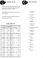
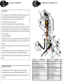
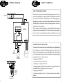
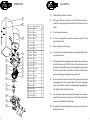
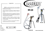
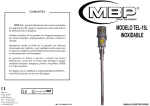
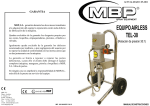
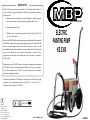
WARRANTY M.B.P., will any repairs necessary during the first 12 months after purchase of a new unit, with the exceptions shown under 1 and 2 below, and under the conditions shown in item 3. 1.- Damage caused by external abuse, customer negligence, or failure to operate the unit in accordance with the instructions supplied with the unit. SPRAY EQUIPMENT 2.- Normal maintenance items. 3.- Within the first 12 months after purchase, M.B.P. will pay 100% of the cost of covered repairs. In no case will M.B.P.liability extend beyond repair or repalacement of the equipment. Such liability is limited to the amount of the original purchase price paid for the unit, minus a reasonable deduction for the time the unit has been in service. It is the responsibility of the purchaser under this warranty to ship or deliver the failed paint sprayer to the authorized service center at the purchaser’s expence. Parts or components covered under this warranty may either be repaired or replaced at M.B.P. option. ELECTRIC PAINTING PUMP KS 2300 Equipent not covered by M.B.P. warranty. Accessories or components of equipment sold by M.B.P. that are nort manufactured by M.B.P. are subject to the warranty, if any, of their manufacturer. M.B.P. will provide purchaser with reasonable assistance in making such claims. The Industry Department of The Basque Goverment, states that all electric and pneumatic airless equipment manufacture by M.B.P. S.L., follows the ’’CE’’ standards under the number 83/392/CEE. 94 / 9 / EC ATEX MBP, S.L. Plgno. Ansoleta, C. Anboto, 17 01006 VITORIA Tfno. 34 945 132744 Fax. 34 945134756 e-mail: info@mbpspray.com www.mbpspray.com IMP 036-MARZO 2015 I.MANUAL DECLARACION DE CONFORMIDAD ‘’CE’’ ‘’EC’’ DECLARATION OF CONFORMITY MODELO / MODEL KS 2300 Este producto cumple con la siguiente directiva de la Comunidad Europea. This Product complies with the following European Comunity Directive. Directiva 2006/42/CEE y 94/9/CEE Atex sobre máquinas. Machinery Directive 2006/42/EC and 94/9/EC Atex Directive. APROBADO POR / APPROVED BY AITOR ORTIZ FECHA / DATE MBP, S.L. figura inscrita en el Registro Industrial del País Vasco con el Nº 01/8030 y cumple los requisitos para el desarrollo de su actividad comercial. MBP, S.L. is registered in the Industrial Register of the Basque Country with the Nº 01/8030. INDEX Pump components ............................... 1 Safety warnings .................................. 3 Operating instructions .......................... 5 Cleaning ........................................... 6 Troubleshooting chart .......................... 7 Parts drawing & list ............................ 9 Wiring diagram .................................. Pressure control assy ......................... 12 Shutdown and care ............................ 13 Standard spray tips ............................. 13 ........................................ 14 Accesories 15 11 PUMP COMPONENTS ACCESORIES SIEVE PACKOIL REF. GR.70.70-70 MESH REF. GR.71.20-120 MESH REF: B.100.20 12 1 1 13 7 10 AIRLESS GUN FILTER REF. J.260.01 MESH 50 COLOUR WHITE J.260.02 100 YELLOU J.260.03 200 RED 10 11 J.271 7 J.272 J.275 6 TIP EXTENSIONS 90cms. 30cms. 4 HP FILTER SCREEN 5 9 1 3 2 REF: G.100.20-60 MESH REF: G.100.05-100 MESH REF: G.100.21-200 MESH 8 14 SHUTDOWN AND CARE PUMP COMPONENTS * Check the packing nut daily. First follow the Pressure Relief Procedure. Be sure the packing nut is 1/3 full of Oilpack at all times to help prevent fluid buildup on the piston rod and premature wear of packings. * Clean the fluid filter often and wherenever the sprayer is stored. First follow the Pressure relief procedure. * Flush the sprayer at the end of each work day and fill it with mineral spirits to help prevent pump corrosion and freezing. 1.- Pressure regulator. Ref: 100.610.00 2.- On / Off switch. Ref: CEA.026 3.- Pressure drain valve. Ref: 100.420.00 4.- Suction pipe. Ref: 102.300.00 STANDARD SPRAY TIPS 13 .013’’ 13.20 13.40 13.60 .015’’ 15.20 15.40 15.60 .017’’ 17.20 17.40 17.60 .019’’ 19.20 19.40 19.60 0.45 100-150 200-250 300-350 0.64 100-150 200-250 300-350 0.87 100-150 200-250 300-350 1.13 100-150 200-250 300-350 1.36 100-150 200-250 300-350 0.53 MM. .011’’ 11.20 11.40 11.60 0.30 100-150 200-250 300-350 .021’’ 21.20 21.40 21.60 1.74 100-150 200-250 300-350 0.63 MM. 0.58 MM. .009’’ 9.20 9.40 9.60 .023’’ 23.20 23.40 23.60 2.08 100-150 200-250 300-350 .025’’ 25.20 25.40 25.60 2.49 100-150 200-250 300-350 0.79 MM. 0.74 MM. 0.68MM. 0.48 MM. 0.43 MM. 0.38 MM. 0.33 MM. 0.28 MM. 0.23 MM. ORIFICE SIZE FLOW IN FAN WIDTHAT ORIFICE SIZE FLOW IN FAN WIDTH AT MM/INCHES LITRES/MIN MM/INCHES LITRES/MIN 300 MM. 300 MM. .027’’ 27.20 27.40 27.60 2.91 100-150 200-250 300-350 3.33 100-150 200-250 300-350 3.86 100-150 200-250 300-350 .029’’ 29.20 29.40 29.60 .031’’ 31.20 31.40 31.60 5.- Displacement pump. Ref: 102.200.00 6.- Check that the product doesn’t leak. Put a drop of oil. 7.- Trasmitting pressure. Ref: 100.410.00 8.- Pressure control assy. Ref: 102.600.00 9.- Strainer. Ref: D.910.00 10.- Paint outlet. Ref: G.100.06 11.- Wire. Ref: 102.630.00 12.- Troley. Ref: 102.500.00 13.- Gun. Ref: J.600.00 2 SAFETY WARNINGS PRESSURE CONTROL ASSY ATTENTION 3 26 This equipment generates very high fluid pressure. High pressure spray can cause serious injury. Read and understand all instructions before operating. Never point the spray gun at anyone or at any part of the body. Never put hand, fingers over the spray tip. Always have the tip guard in place on the spray gun while spraying. High pressure fluid in the hoses can be very dangerous. If the hose develops a leak, split or rupture due to any kind of wear, damage or misuse, the high pressure spray emitted from it can cause a fluid injection injury or other serious bodily injury or properly damage. Never use a damaged hose Tighten all fluid connections securely before each use. High pressure fluid can dislodge a loose coupling or allow high pressure spray to be emitted from the coupling. Proper hose grounding continuity is essential to maintaining a grounded spray system. If any fluid appears to penetrate your skin, get emergency medical care at once. Do not treat as a simple cut. Tell the doctor exactly what fluid was injected. All chemicals used in the pump must be compatible with the wetted parts of the pump. 22 12 This pump can develope 240 bar working pressure. Be sure that all spray equipment and accesories used are rated to withstand this pressure. Do not exceed the maximum working pressure of any component or accessory used in the system. 3 4 23 2 15 5 11 6 28 25 28 17 9 27 8 20 1 19 18 15 7 Nº PRESSURE HAZARD 24 REF. 1 102.600.01 2 102.600.02 3 CEA.041 4 100.610.00 5 100.640.00 6 100.620.00 7 100.630.00 8 CTB.005 9 CAR.254 11 CTJ.005 12 CTU.015 15 CEA.034 DESCRIPTION BOX COVER FRECUENCY INVERTER PRESSURE REGULATOR INVERTER OUTLET CABLE INVERTER ON/OFF SWITCH CABLE WIRE SCREW WASHER SCREW NUT CONNECTOR 21 Q Nº 1 1 1 1 1 1 1 1 2 2 2 2 17 18 19 20 21 22 23 24 25 26 27 28 REF. DESCRIPTION CEA.026 CEA.027 CEA.030 100.660.00 100.411.00 CEA.037 F.900.20 100.600.03 CAR.022 100.650.00 CTU.105 CTB.013 ON/OFF SWITCH CONNECTOR NUT MOTOR CABLE PRESSURE TRANSMITTER C. CONTROL CAR CONNECTOR BOX WASHER CONTROL CAR INVERTER C. NUT SCREW Q 1 1 1 1 1 1 3 1 4 1 5 4 12 WIRING DIAGRAM SAFETY WARNINGS FIRE OR EXPLOSION HAZARD BROWN 220 V 50 Hz. BROWN 1 0 BLUE BLUE L3 L1 PE LI 1 COM FREQUENCY INVERTER +24 Static electricity is created by the flow of fluid through the pump and hose. If every part of the spray equipment is not properly grounded, sparking may occur and the system may become hazardous. Sparking may also occur when plugging in or unplugging a power supply cord. Sparks can ignite fumes from solvents and the fluid being sprayed, dust particles, whether you are spraying indoors or outdoors, and can cause a fire or explosion. If you experience any static sparking or even a slight shock while using the equipment, stop spraying immediately. Check the system for proper grounding. Do not use the system again until the problem has been identified and corrected. W V U PE COM 2 1 +24 +24 COM 6 3 4 5 7 COM 9 8 LI 1 10 GREY 1 GREEN 2 WHITE 3 BROWN 3 2 PRESSURE RELIEF PROCEDURE 1 MOTOR PRESSURE REGULATOR COM 2 1 +24 +24 COM 6 3 4 5 7 COM 9 8 LI 1 10 GREY 1 4 2 3 1 2 3 4 BROWN YELLOW GREEN WHITE To reduce the risk of serious bodily injury, including fluid injection, splashing fluid or solvent in the eyes or on the skin, or injury from moving parts or electric shock, allways follow this procedure whenever you shut off the sprayer, when checking or servicing any part of the spray system, when installing, cleaning or changing spray tips, and whenever you stop spraying: · Engage the gun safety latch · Turn the ON/OFF switch to OFF (red) · Unplug the power supply cord (No. 14) · Disengage the gun safety latch. Hold a metal part of the gun to the side of a grounded metal pail, and trigger the gun to relieve pressure. · Engage the gun safety latch · Open the pressure drain valve (No. 3), having a container ready to catch the drainage PRESSURE TRANSMITTER 11 4 OPERATION PART LIST DISPLACEMENT PUMP 1.- Connect hose and gun (use two wrenches to tighten the fittings). Don´t install the spray tip yet. Nº REF. 1 2.- Check the electrical service. Be sure the electrical installation is properly rated for the sprayer and that the outlet you use is properly grounded. Use an extension cord which has 3 wires of a minimum 4 mm size, and a maximum of 45 m long. Longer lengths may affect sprayer performance. 3 4 5 3.- Prepare the paint. Stir the paint to mix pigments. Strain the paint to remove particles that could clog the filters or spray tip. 7 6 27 8 4.- Put the suction tube into the pail container. 5.- Lower the pressure setting by turning the pressure adjusting knob all the way counterclockwise 20 26 28 24 25 9 21 6.- Disengage the gun safety latch. 10 7.- To prime the pump, hold a metal part of the gun firmly into a metal waste container. Squeeze the trigger and hold it open, turn the ON/OFF switch to ON, and slowly increase the pressure setting until the sprayer starts. Keep the gun triggered until all air is forced out of the system and the paint flows freely from the gun. Release the trigger and engage the gun safety latch. 10 23 22 29 11 30 11 31 12 13 36 15 Note: If the pump is hard to prime, place a container under the pressure drain valve and open it. When fluid comes from the valve, close it. Then disengage the gun safety latch and proceed as in point 7. 8.- Check all fluid connections for leaks. If any are found, follow the pressure relief, before tightening connections. 14 16 18 17 35 19 34 38 33 9.- Install the spray tip and tip guard. Be sure the gun safety latch is engaged. Note: your new sprayer was factory tested in lightweight oil which was left in to protect pump parts. before using water-base paint, flush with mineral spirits followed by clean water. Before using oil-case paint, flush with mineral spirits only. 10.- Fill the packing nut with MBP - Packoil 5 32 37 1 *3 4 5 6 *7 *8 9 *10 *11 12 13 14 15 *16 17 18 19 20 21 22 23 24 25 26 27 28 29 30 31 32 33 34 35 36 37 38 102.210.00 CB0.110 080.230.00 102.200.03 102.200.04 CJT.044 102.200.05 102.200.01 102.200.06 CJT.045 102.200.07 102.200.08 080.200.10 080.200.11 CB0.111 102.220.00 102.200.09 102.200.02 CPA.218 CTB.036 CAR053 100.420.00 G.100.06 CJT.164 100.410.01 CEA.027 100.411.00 CNA.057 G.920.03 MAPM.203 102.310.00 CJT.175 102.300.01 CC0001 MAPM.202 102.320.00 D.910.00 DESCRIPTION Q Rod Ball Seat ball Tapón Sleeve O-ring Packings Body Packings O-ring Sleeve Joint Sleeve-guide Pin Ball Seat Joint Valve housing Pin Screw Washer Valve Nipple Joint Body Packing nut Sensor Nipple Spring Tube Suction Joint Nipple Clamp Hose Tube Strainer 1 1 1 1 1 1 1 1 2 2 1 1 1 1 1 1 1 1 2 2 2 1 1 1 1 1 1 1 1 1 1 1 1 2 1 1 1 *KIT 043: Includes packings (up & down) packing glands and balls. 10 PARTS LIST CLEANING 20 1.- Follow the Pressure Relief Procedure. 2.- If the sprayer has been used before, remove the filter bowl and screen. Clean the screen separately and install the bowl without the screen to flush it. 3.- Close the pressure drain valve 4.- For 2 liters of compatible solvent into a grounded metal pail. Put the suction tube in the pail. 5.- Remove the spray tip from the gun 6.- Lower the pressure setting by turning the pressure adjusting knob all the way counterclockwise. 7.- Hold a metal part of the gun against a metal container. Squeeze the trigger and hold it open, turn the ON/OFF switch to ON, and slowly increase the pressure setting until the sprayer starts. Keep the gun triggered until all air is forced out of the system and the solvent flows freely from the gun. Release the trigger and engage the gun safety latch. 8.- Remove the suction tube from the pail. Disengage the gun safety latch and trigger the gun to force solvent from the hose. Do not let the pump run dry for more than 15 seconds to avoid damaging the pump packings. Then follow the Pressure Relief Procedure. 9.- Leave the pressure drain valve open until you are ready to use the sprayer again. If the screen was removed, unscrew the filter bowl and reinstal the clean screen. Reinstall the bowl, hand tight. 21 Nº 1 2 REF. DESCRIPTION Q 1 102.110.00 Motor 1 2 CTB.003 Screw 4 3 102.111.01 Housing 1 4 CTB.014 Screw 4 5 CPA.204 Pin 2 6 CB1010 2 Sleeve 7 A1.920.02 Gear 1 8 CB1012 Bearing 1 9 CB2007 Washer 1 4 10 A1.920.03 Gear 1 3 11 CB2008 1 8 5 12 A1.910.02 Rod 1 9 6 13 CPA.501 Cotter pin 1 7 14 102.111.02 Body 1 6 15 CB1009 1 5 10 11 Washer Bearing 16 102.121.00 Rod 1 17 CB2002 1 Sleeve 13 18 102.120.02 Rod 1 12 19 A1.930.03 Pin 1 20 102.100.01 Cover 1 21 CTB.204 Screw 4 14 15 16 10.- If you flushed with mineral spirits and are going to use water-base paint, flush with clean water. 17 18 9 19 6 TROUBLESHOOTING CHART TROUBLE CAUSE SOLUTION TROUBLE CAUSE SOLUTION Unit will not prime Dried out piston packings. Stuck valve balls. Remove siphon tube and feel lower ball check to be sure it is free to move off it is seat. Place full cup of paint thinner over end of fluid section and turn on pump. Unit will not build or maintain pressure. Fuid leak. Check for external leaks including hydraulic fittings attached to pressure control housing. Pump inlet screen plugged. Air in pump or hose Remove and clean. Hold gun trigger in open position and run unit about 10 seconds until air is purged. Check for siphon tube leak. Fluid too viscous. Consult manufacturers recommendations on paint container label. Too large a spray tip. Change tip. Packings worn. Fluid too viscous. Unit will not build or maintain pressure. 7 Replace. Prime pump with compatible solvent. Bring up to pressure, carefully remove pump from solvent container and immerse inlet tube into heavy material to be sprayed. With nozzle tip removed trigger gun until heavy material appears at gun. Replace nozzle tip and you are ready to spray. Fuid leakage out relief hole Worn packing. at pressure control. Repack or replace transducer. Fluid leakage at upper end of fluid section. Upper packings worn. Relieve pressure and tighten packing take up nut or replace packings. Piston rod worn. Replace. Bad spray pattern. Too large a tip size. Pressure adjustment wrong. Insufficient fluid delivery. Change to a smaller tip size. Adjust pressure control knob. Clean all straines and filters in system. Fuid too viscous. Add solvent to fluid according to manufacturer’s recommendations. Siphon tube clogged. Siphon tube air leak. Clogged tip. Remove and clean. Check connection and seal. Relieve pressure, remove tip and clean. Pressure adjusting knob not properly set. Pump inlet strainer dirty. Valve balls or seats worn or dirty. Air in pump or hose. Adjust to increase pressure. Hold gun trigger in open position and run about 10 seconds until airs is purged. Unit lacks power. Pressure adjustment low. Improper voltage supply. Increase. Reconnect input voltage accordingly. Packings worn. Worn spray tip. Internal leakage. Replace. Replace. With gun trigger closed, allow unit to pump up to pressure and shut off if pump momentarily starts, internal leak is indicated and fluid section rebuild is necesary. Blown fuses at pump. Excessive pressure. Have Service Center recalibrate the pressure control. Excesive extention cord length or improper wire gauge. Use 3x1,5 mm. section wire or larger up to maximum of 50 meters. For additional lenght, more airless hose may be used. Clean or temporaly remove. Replace or clean. 8