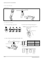
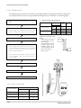
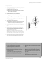
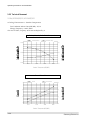
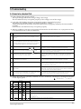
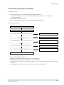
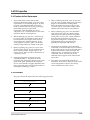
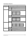
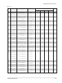
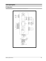
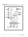
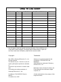
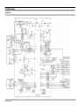
1
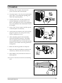
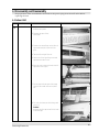
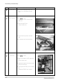
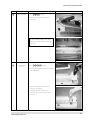
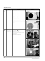
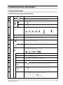
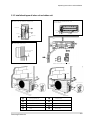
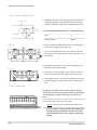
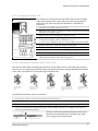
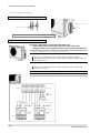
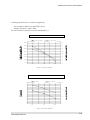
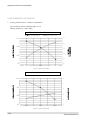
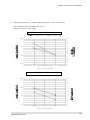
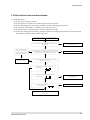
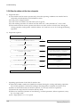
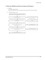
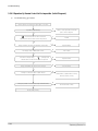
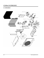
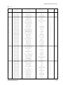
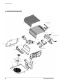
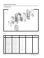
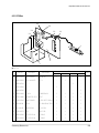
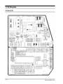
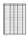
ROOM AIR CONDITIONER
INDOOR UNIT
AD24A1(B1)E12
AD18A1(B1)E09
AD19A1(B1)E07
AD19A1(B1)E12
SERVICE
OUTDOOR UNIT
UD24A1(B1)E2
UD18A1(B1)E2
UD19A1(B1)E2
Manual
AIR CONDITIONER
CONTENTS
1. Precautions
2. Product Specifications
3. Operating Instructions and
Installation
4. Disassembly and Reassembly
5. Troubleshooting
6. Exploded Views and Parts List
7. PCB Diagrams
8. Wiring Diagrams
9. Schematic Diagrams
© Samsung Electronics Co., Ltd. NOV. 1998.
Printed in Korea.
Code No. DB81-10179A(1)
1. Precautions
1. Warning: Prior to repair, disconnect the
power cord from the circuit breaker.
2. Use proper parts: Use only exact replacement
parts. (Also, we recommend replacing parts
rather than repairing them.)
3. Use the proper tools: Use the proper tools
and test equipment, and know how to use
them. Using defective tools or test equipment
may cause problems later-intermittent contact,
for example.
Fig. 1-1 Avoid Dangerous Contact
4. Power Cord: Prior to repair, check the power
cord and replace it if necessary.
5. Avoid using an extension cord, and avoid tapping into a power cord. This practice may
result in malfunction or fire.
6. After completing repairs and reassembly,
check the insulation resistance. Procedure:
Prior to applying power, measure the resistance between the power cord and the ground
terminal. The resistance must be greater than
30 megohms.
Fig. 1-2 No Tapping and No Extension Cords
7. Make sure that the grounds are adequate.
8. Make sure that the installation conditions are
satisfactory. Relocate the unit if necessary.
9. Keep children away from the unit while it is
being repaired.
10. Be sure to clean the unit and its surrounding
area.
Fig. 1-3 No Kids Nearby!
Fig. 1-4 Clean the Unit
Samsung Electronics
1-1
MEMO
1-2
Samsung Electronics
4. Disassembly and Reassembly
Stop operation of the airconditioner and remove the power plug from the wall outlet before
repairing the unit
4-1 Indoor Unit
No
Parts
1
Front Grille
Procedure
Remark
1) Stop the air conditioner operation and
block the main power.
2) Seperate the tape of front.
Panel upper.
3) Contract the second finger to the left and
right handle and pull to open the inlet
grille.
4) Take the left and right filter out.
5) Loosen one of the right fixing screw and
seperate the terminal cover.
6) Open the cover screw and loosen three fixing screws of front grille.
7) Pull the upper left and right of discharge
softly for the outside cover to be pulled
out.
8) Pull softly the lower part of discharge and
push it up
Caution:
Assemble the front panel and fix the hooks
of left and right.
Samsung Electronics
4-1
Disassembly and Reassembly
No
Parts
Procedure
2
Filter Frame
1) Loosen the left and right screw of the
Holder Filter, and Separate the Holder
Filter.
3
Ass'y Tray Drain
1) Do " 1 2 ", above.
Separate the holder at the rear side of
Indoor unit.
Remark
2) Take the display PCB out.
(Center of indoor unit).
3) Loosen three fixing screws of left and
right.
4) Pull tray drain out from the back body.
4
Main PCB
1) Do " 1 2 ", above
2) Take all the connector of PCB upper side
out.
(Inclusion Power cord)
3) Separate the outdoor unit connection wire
from the terminal block.
4) If pulling the Main PCB up. it will be taken
out.
(Separate the TRANS hook. it before).
4-2
Samsung Electronics
Disassembly and Reassembly
No
Parts
5
Heat Exchanger
Procedure
Remark
1) Do " 1 2 3 4 ", above.
2) Loosen the left screws of the heat
exchanger.
Lifting the heat exchanger up a little to
push the up side for separation from the
indoor unit
6
Fan Motor and
Cross Fan
1) Do " 1 2 3 4 5 ", above.
2) Loosen the fixing two screws and separate
the motor holder.
3) Loosen the fixing screw of motor fan.
(By use of M3 wrench)
Separate the motor from the fan.
Separate the fan motor the left holder
bearing.
Samsung Electronics
4-3
4-2 Outdoor Unit
No
Parts
1
Cabinet
Procedure
1) Turn off the unit and remove the power
cable
2) Remove the top cover.
3) Remove the control box cover.
4) Unplug the ass'y cable.
5) Remove the cabi-side.
6) Remove the cabi-front.
* When you assemble the parts, check if the
each parts and electric connectors are fixed
firmly.
Remark
<UD24A1(B1)E2>
<UD18A1(B1)E2/UD19A1(B1)E2>
<UD24A1(B1)E2>
2
Fan Motor &
Propeller Fan
1) Do Procedure 1 above.
2) Remove the nut flange.
(Turn to the right to remove as it is a left
turned screw)
3) Disassemble the propeller fan.
<UD18A1(B1)E2/UD19A1(B1)E2>
4-4
Samsung Electronics
3. Operating Instructions and Installation
3-1 Operating Instructions
3-1-1 Name & Function of Key in remote controller
NO
FUNCTION OF KEY
NAME OF KEY
On/Off Button. Use this button to start and stop air conditioner.
1
2
(UP)
Temp. up button.
If the button is pressed once, the setting temperature is increased by 1°C
(DOWN)
Temp. down button.
If the button is pressed once, the setting temperature is decreased by 1°C
Each time you press this button,
MODE is changed in the following order.
3
: Auto Mode
: Cool Mode
: Dry Mode
MODE
4
TURBO
Use this button to provide heavy duty cooling & Heating for 30 minutes.
5
OFF
Set up the reserve or cancel the timer off quickly
6
Use this button for sleep operation.
(The SLEEP mode can be selected at COOL and HEAT mode.)
7
Adjusts air flow vertically,
each time you press this button.
Each time you press this button,
FAN SPEED is changed in the following order.
8
9
10
11
12
13
: Fan Only
: Heat Mode
C
O
V
E
R
T
I
M
E
R
ON TIMER
Set up the time that operation start.
OFF TIMER
Set up the time that operation stop.
SET
Use this button to reserve the timer on and timer off.
CANCEL
Use this button to cancel the timer on and timer off.
(UP)
If the
button is pressed once, the time increase by one minute
during the time set mode, and ten minutes during the timer set mode.
(DOWN)
If the
button is pressed once, the time decrease by one minute
during the time set mode, and ten minutes during the timer set mode.
14
15
TIME
Samsung Electronics
Without regard to ON/OFF condition in remote controller,
use this button to set current time.
Adjust the current time using
button.
(Data can be transmitted after setting up the time)
3-1
Operating Instructions and Installation
3-1-1(a) Heat Pump
1. AUTO MODE : In this mode, operation
mode(COOL, HEAT, DRY) is selected automatically by the room temperature of initial
operation.
Room Temp
Operation Type
Tr≥ 21°C+∆T
Cool Operation (Set Temp:AUTO SETTING)
21°C +∆T>Tr
Heat Operation (Set Temp : 22°C+∆T)
∆T= -2°C, -1°C, 0°C, +1°C, +2°C
∆T is controlled by setting temperature
up/down key of remote controller
2. COOL MODE : The unit operates according
to the difference between the setting and
room temperature. (18°C~30°C)
3. HEAT MODE : The unit operates according
to the difference between the setting and
room temperature.(16°C~30°C)
*Prevention against cold wind : For about
3~5 minutes after initial operation, thermo
control or “de-ice”, the indoor fan will
either not operate or operate very slowly(510 rpm), then switch to the selected fan
speed. This period is to allow the indoor
unit's heat-exchanger to prewarm before
emitting warm air.
*High temperature release function : The
outdoor unit for and compressor ON/OFF
control for safety operation, when the overheat is heat exchanger of indoor unit.
*De-ice : Deicing operation is controlled by
indoor unit's heat exchanger temperature
and accumulating time of compressor's
operation.
De-ice end by sensing of the processing
time by de-ice condition.
3-2
4. DRY MODE : Has 3 states, each determined
by room temperature.
The unit operates in DRY mode.
*Compressor ON/OFF Time is controlled
compulsorily(can not set up the fan speed,
always breeze).
*Protective function : Low temperature
release. (Prevention against freeze)
5. TURBO MODE : This mode is available in
AUTO, COOL, HEAT, DRY, FAN MODE.
When this button is pressed at first, the air
conditioner is operated “powerful” state for
30 minutes regardless of the set temperature, room temperature.
When this button is pressed again, or when
the operating time is 30 minutes, turbo
operation mode is canceled and returned to
the previous mode.
*But, if you press the TURBO button in DRY
or FAN mode that is changed with AUTO
mode automatically.
6. SLEEP MODE : Sleep mode is available
only in COOL or HEAT mode.
The operation will stop after 6 hours.
*In COOL mode : The setting temperature
is automatically raised by 1°C each 1hour
When the temperature has been raised by
total of 2°C, that temperature is maintained.
*In HEAT mode : The setting temperature
is automatically droped by 1°C each 1hour.
When the temperature has been droped by
total of 2°C, that temperature is maintained.
7. FAN SPEED : Manual (3 step), Auto (4 step)
Fan speed automatically varies depending
on both the difference between setting and
the room temperature.
Samsung Electronics
Operating Instructions and Installation
8. COMPULSORY OPERATION :
For operating the air conditioner without
the remote controller.
*AUTO : The operating is the same function that AUTO MODE in the remote controller.
9.
SWING : BLADE-H is rotated vertically by
the stepping motor.
*Memory louver : When ON/OFF button is
pressed at stop state, the BLADE-H returns
to its original location which is operating
state before stop
*Swing Set : Press the
button under the
remote control is displayed on LCD the
,
and the blades move up and down, about 43°.
If the one more time press the
button, blatles location is stop.
10. Quick OFF TIMER: OFF timer (quick timer)
allows reservation or cancel the timer off
quickly
When OFF timer button is pressed at operating state, LCD displays the polling state
sequentially.
The LCD also displays the time remaining.
Samsung Electronics
11. 24-Hour ON/OFF Real Setting Timer. : The
air conditioner is turned ON at a specified
time using ON TIMER .
OFF TIMER : The air Conditioner is turned
OFF at a specified time using OFF TIMER .
*ON TIMER : Only timer LED lights on.
*OFF TIMER : Both timer and operation
LED lights on.
*3 minutes delay timer.
12. SELF Diagnosis
LED DISPLAY
Check Point
operation TIMER FAN Turbo
Interruption of electric power and Power on.
Abnormal condition of the room sensor.
Abnormal condition of the indoor unit's heat exchanger sensor.
Indoor unit fan motor lock.
: LED blinking
: LED off
13. BUZZER SOUND : Whenever the ON/OFF
button is pressed or whenever change
occurs to the condition which is set up or
select, the compulsory operation mode,
buzzer is sounded "beep"
3-3
3-2 Installation
3-2-1 Selecting Area for Installation
Select an area for installation that is suitable
to the customer's needs.
3.
3-2-1(a) Indoor Unit
1. Make sure that you install the indoor unit in
an area providing good ventilation. It must
not be blocked by an obstacle affecting the
airflow near the air inlet and the air outlet.
2. Make sure that you install the indoor unit in
an area allowing good air handling and
endurance of vibration of the indoor unit.
3. Make sure that you install the indoor unit in
an area where there is no source of heat or
vapor nearby.
4. Make sure that you install the indoor unit in
an area from which hot or cool air is spread
evenly in a room.
5. Make sure that you install the indoor unit in
an area away from TVs, audio units, cordless phones, fluorescent lighting fixtures
and other electrical appliances (at least 1
meter).
6. Make sure that you install the indoor unit in
an area which provides easy pipe connection with the outdoor unit, and easy
drainage for condensed water.
7. Make sure that you install the indoor unit in
an area which is large enough to accomodate the measurements shown in figure on
the next page.
3-2-1(b) Outdoor Unit
1. Make sure that you install the outdoor unit
in area not exposed to the rain or direct sun
light.
(Install a separate sunblind if exposed to
direct sun light.)
2. Make sure that you install the outdoor unit
in area allowing good air moment, not
amplifying noise or vibration, especially to
4.
5.
6.
7.
8.
avoid disturbing neighbours.
(Fix the unit firmly if it is mounted in a
high place.)
Make sure that you install the outdoor unit
in area providing good ventilation and
which is not dusty. It must not be blocked
by any obstacle affecting the airflow near
the air inlet and the air outlet.
Make sure that you install the outdoor unit
in area free from animals or plants.
Make sure that you install the outdoor unit
in area not blocking the traffic.
Make sure that you install the outdoor unit
in area easy to drain condensed water from
the indoor unit.
Make sure that you install the outdoor unit
in area which provides easy connection
within the maximum allowable length of a
coolant pipe (10 meters).
Note
1. Add 10 grams of refrigerant (R-22) for
every 1 meter if the pipe length exceeds
the standard pipe length of 5 meters.
2. Maintain a height between the indoor and
outdoor units of less than 3 meters.
Make sure that you install the outdoor unit
in an area which is large enough to accommodate the measurements
shown in figure on the next page.
3-2-1(c) Remote Control Unit
1.
Make sure that you install the remote control unit in an area free from obstacles such
as curtains etc, which may block signals
from the remote control unit.
2. Make sure that you install the remote control unit in an area not exposed to
direct sunlight, and where there is no source
of heat.
3. Make sure that you install the remote control unit in an area away from TVs, audio
units, cordless phones, fluorescent lighting
fixtures and other electrical appliances (at
least 1 meter).
Caution
It is harmful to the air conditioner if it is used in the following environments: greasy areas (including areas near machines),
salty areas such as coast areas, areas where sulfuric gas is present such as hot spring areas. Contact your dealer for advice.
3-4
Samsung Electronics
Operating Instructions and Installation
3-2-2 Installation diagram of indoor unit and outdoor unit
A Indoor unit gas leak test check point
Indoor unit
Piping may be laid to the rear, left,
right or down .
3
Left
Right
2
Rear
Piping
Down
Rear
Tape vinyl
1
B Drain hose installation
Cut the piping hole
sloped slightly
Remote control holder Remote control
A-UNIT
Outdoor unit check point
B-UNIT
10
1
Piping (Liquid) 1/4”
6
Clamper tube
2
Piping (Gas) 1/2”, 3/8”
7
Installation plate
3
Installation tube
8
Pipe-connection
4
Vinyl tape
9
Screw
5
Putty
10
Drain hose
Samsung Electronics
3-5
Operating Instructions and Installation
3-2-2(a) Fixing the Installation Plate
1. Determine the position of the pipe and drain hose hole
using the right figure and drill the hole with an inner
diameter of 65mm so that it slants slightly downwards.
Installation plate
Pipe hole
(ø65mm)
2. If you are fixing the indoor unit to a… Then follow Steps…
Wall
3.
Window frame
4 to 6.
3. Fix the installation plate to the wall in a manner appropriate to the weight of the indoor unit.
(Unit : mm)
If you are mounting the plate on a concrete wall with
anchor bolts, the anchor bolts must not project by more
than 20mm.
280
(Unit : mm)
340
4. Determine the positions of the wooden uprights to be
attached to the window frame.
5. Attach the wooden uprights to the window frame in a
manner appropriate to the weight of the indoor unit.
6. Using tapped screws, attach the installation plate to the
wooden uprights, as illustrated in the last figure opposite.
3-2-2(b) Purging the Unit
On delivery, the indoor unit is loaded with an inert gas.
All this gas must therefore be purged before connecting the
assembly piping. To purge the inert gas, proceed as fol lows.
Unscrew the caps at the end of each pipe.
Result : All inert gas escapes from the indoor unit.
•
3-6
To prevent dirt or foreign objects from getting into
the pipes during installation, do NOT remove the
caps completely until you are ready to connect the
piping.
Samsung Electronics
Operating Instructions and Installation
3-2-2(c) Connecting the Assembly Cable.
The outdoor unit is powered from the indoor unit via the assembly
cable. If the outdoor unit is more than five metres away from the
indoor unit, the cable must first be extended to a maximum of
ten metres.
1. Extend the assembly cable if necessary.
2. Open the front grille by pulling on the tabs on the lower right and
left sides of the indoor unit.
3. Remove the screw securing the connector cover.
4. Pass the assembly cable through the rear of the indoor unit and
connect the assembly cable to terminals 1, 2, 3, 5.
Indoor unit
• Each wire is labelled with the corresponding terminal number.
5. Firmly fix the ass’y cable with clamp wire holder.
6. Pass the other end of the cable through the 65mm hole in the wall.
7. Replace the connector cover, carefully tightening the screw.
Outdoor unit
1
(L)
2
3
(N) COM
E
Earth
8. Close the front grille.
9. For further details on how to plug the other end of the assembly
cable into the outdoor unit, refer to page 3-8.
3-2-2(d) Installing and Connecting the Indoor Unit Drain Hose
Care must be taken when installing the drain hose for the indoor unit to ensure that any condensa tion water is correctly drained outside.l When passing the drain hose through the 65mm hole drilled
in the wall, check that none of the following situations occur.
The hose must
NOT slope upw
ards.
The end of the drain
hose must NOT be
placed in water.
Do NOT bend the
hose in different
directions.
Keep a clearance of at
least 5cm between the
end of the hose and the
ground.
Do NOT place the end
of the drain hose in a
hollow.
To install the drain hose, proceed as follows.
1. If necessary, connect the 2-metre extension to the drain hose.
2. If you are using the extension, insulate the inside part of the extension drain hose with a shield.
3. Pass the drain hose under the refrigerant piping, taking care to keep the drain hose tight.
4. Pass the drain hose through the hole in the wall, making sure that it is sloping downwards, as
shown in the illustrations above.
The hose will be fixed permanently into position once
the whole installation has been tested for gas leaks;
refer to page 16 for further details.
Shield
Drain hose
Samsung Electronics
Extension drain hose
3-7
Operating Instructions and Installation
3-2-2(e) Outdoor unit installation
GAS LEAK TEST
Outdoor unit check point
Indoor unit check point
Check for gas leak from the flare nut connections with leak detector.
WIRING CONNECTION
Two electric cables must be connected to the outdoor unit:
• The assembly cable connecting the indoor unit to the outdoor unit.
• The power cable connecting the auxiliary circuit breaker to the outdoor unit.
1 Remove the terminal board cover on the side of the outdoor unit.
2 Connect the assembly cable to terminals 1 to 5 and connect the power cable to therminals A to B.
Each wire is labelled with the corresponding terminal number.
Ensure the wire number of the indoor unit and the terminal number of
the outdoor unit.
3 Connect the earth wires to the earth terminals.
Refer to the page opposite for further details on how to check that
earthing is correct.
4 Replace the terminal board cover, carefully tightening the screw.
5 Connect the power cable to the auxiliary circuit breaker.
Outdoor unit
1
(L)
2
3
(N) COM
1
(L)
3
2
(N) COM
1
(L)
2
(N)
Terminal Block
Earth
terminal
Circuit Breaker
(Main Power supply cable)
Earth
terminal
Earth
terminal
Assembly cable
Earth
Earth
Indoor unit
A-unit
3-8
B-unit
Samsung Electronics
Operating Instructions and Installation
Installation of drain line
In heating and ”de-ice” operation, condensed
water may be generated.
Install drain line as following procedure.
Drain hole
1. Insert drain plug into hole and then connect
drain hose to drain plug.
• Inside diameter of drain hose is 18mm
Drain plug
Grounding
(The parts for this work are optional)
• A grounding terminal can be found on
the outdoor unit as illustrated.
1. When an existing grounding terminal is avilable.
(Grounding wire of ø1.6mm or larger<solid
wire>or 2mm 2 or larger <standard wire>)
Terminal used
exclusively for
grounding
Grounding resistance:
less than 100 ohms
(existing grounding electrode)
Grounding screw hole
2. Use of a grounding electrode.
• Specifications of grounding electrode.
Carbon plastic
Steel core
PVC-insulated wire(2mm2x3.5m), green
Samsung Electronics
Terminal, M4
3-9
Operating Instructions and Installation
3-2-2(f) Flare Modification
• Tools used
Flare modification procedure
1) Cut the pipe using a pipe cutter.
90°
Oblique
Raughness
2) Remove burrs at the tip of the pipe cut.
Caution : Burrs not removed may result in
leakage of gas.
Burr
Pipe
Reamer
3) Insert a flare nut into the pipe and modifty flare.
D
A
Outer diameter
ø6.35mm
ø9.52mm
ø12.7mm
A(mm)
1.3
1.8
2.0
* Unproper flaring
Inclined
3-10
Surface
damaged
Cracked
Uneven
thickness
Samsung Electronics
Operating Instructions and Installation
3-2-2(g) Air Purging
CAUTION
The air in indoor unit and in the pipe must be purged. If air remains in the refrigeration pipes, it will affect the compressor,
reduce to cooling/heating capacity, and could lead to a malfuction. Refrigerant for air purging is not charged in the outdoor unit.
Use additional refrigerant as shown at the right figure. Each unit must be purged in turn
1. Check the piping connections
2. Connect the charging hose of low pressure side of
Manifold gauge to the packed valve having a charging
port (3/8” or 1/2” Packed valve)
3. Open the valve of the low pressure side of Manifold
gauge counterclockwise for 10 seconds, and then close
it to closed position.
INDOOR
A-UNIT
4. Check for gas leakage.
- Check the flare connections for gas leakage.
INDOOR
B-UNIT
5. Purge the air from the system.
- Loosen the liquid side(1/4”) flare nut after gas leakage
check
- Open the low pressure side valve of the Manifold
gauge for 10 seconds to purge the air from the system.
Repeat this three times or more.
- Tighten the liquid side(1/4”) flare nut when the low
pressure of the manifold gauge indicates about
0.5Kg/cm2.
liquid side
Gas side
Pipeline
6. Set valve cork of both liquid side and gas side of
packed valve to the open position.
Flare Nut
Valve cork
Pipeline
7. Mount the valve stem nuts to the 2-way and 3-way
valve. And mount the service port cap to 3-way valve
Outdoor
unit
Charging Port
8. Check for gas leakage.
- At this time, especially check for gas leakage from the
3-way valve’s stem nuts, and from the service port cap.
Charging hose of
Low pressure hose
<Structure of 3-way valve>
Samsung Electronics
3-11
Operating Instructions and Installation
3-2-2(h) Refrigerant Refill
If connecting pipe of more than 10 metres is installed, additional refrigerant should be charged by
extra metre. You don’t have to charge additional refrigerant up to 10 metres of connecting pipe.
1. Remove the valve stem cap and service port of 3-way
valve.
2. Connect the charging hose of low pressure side of
Manifold gauge to the packed valve having a charging
port(1/2” Packed valve) as shown at the right figure.
3. Operate the unit at the cooling mode.
4. Slowly open the valve of the low pressure side of
Manifold gauge counterclockwise until the low pressure of manifold gauge indicates 4.8 to 5.5 kg/cm2 (68
a 78psi) at the high cool operation (1-unit operation)
and the standard temperature.
•
Piping length and the height
Pipe Size
AD24A1(B1)E12
AD19A1(B1)E12
AD18A1(B1)E09
AD19A1(B1)E07
LIQUID
1/4”
1/4”
1/4”
1/4”
Additional refrigerant charge
(R22,g)
• When length of the pipe is
over 5u by the unit, you
should charge
the refrigerant Formulas
A-UNIT : 10gx(L a-10)/m
B-UNIT : 10gx(L b-10)/m
(La:the length of A-unit’s
pipe L b:the length of
B-unit’s pipe)
GAS
1/2”
1/2”
3/8”
3/8”
Max.piping
length
A
15m
15m
15m
15m
Max
height
B
3m
3m
3m
3m
INDOOR UNIT
A
B
OUTDOOR UNIT
It is recommend that refrigerant should be slowly put
in. If the refrigerant is put in too quickly, compressor
will be damaged.
5. Stop operation of the air conditioner.
6. Disconnect the charge hose of manifold gauge.
7. Close the cap of each valve.
INDOOR
A-UNIT
INDOOR
B-UNIT
3-2-2(i) Flare unt fixing torque
Outter diameter
Torque (kg-cm)
Fixing Torque
Final Torque
ø6.35(Liquid Side)
160
200
ø9.52(Gas Side)
300
350
ø12.7(Gas Side)
500
550
3-12
Samsung Electronics
Operating Instructions and Installation
3-2-2(j) Pump down
1. Confirm that both the 2-way and 3-way valves are
set to the open position.
(1) Remove the valve stem caps.
(2) Be sure to use a hexagonal wrench to operate
the Gas side valve stems.
2. Operate the unit for 10 to 15 minutes.
3. Stop operation and wait for 3 minutes, then connect the charge set to the service port of the 3-way
valve.
(1) Connect the charge hose with the push pin to
the service port.
2-Way Valve
4. Air purging of the charge hose.
(1) Open the low-pressure valve on the charge set
slightly to air purge from the charge hose.
Cap
5. Set the liquid side 2-way valve to the closed position.
6. Operate the air conditioner at the cooling cycle
and stop operation immediately after setting the
3-way valve to the closed position when the
gauge indicates 0 kg/cm 2G.
If the unit can not be operated at the Cooling
Mode(weather is rather cool), operate the unit at
the Trubo Mode. So that the unit can be operated.
3-Way Valve
7. Disconnect the charge set, and mount the both 3way valve’s stem nuts and the service port cap.
Relocation of the air conditioner
•
Refer to this procedure when the unit is relocated.
1. Carry out the pump down procedure
(refer to the details of ‘pump down’).
2. Remove the power cord.
3. Disconnect the assembly cable from the
indoor and outdoor units.
4. Remove the flare nut connecting the indoor
unit and the pipe.
At this time, cover the pipe of the indoor
unit and the other pipe using a cap or vinyl
plug to avoid foreign material entering.
Samsung Electronics
5. Disconnect the pipe connected to the outdoor
unit.
At this time, cover the valve of the outdoor
unit and the other pipe using a cap or vinyl
plug to avoid foreign material entering.
6. Make sure you do not bend the connection
pipes in the middle and store together with
the cables.
7. Move the indoor and outdoor units to a new
location.
8. Remove the mounting plate for the indoor
unit and move it to a new location.
3-13
Operating Instructions and Installation
3-2-3 Technical Document
3-2-3(a) AD24A1(B1)E12 / AD19A1(B1)E12
•Cooling Characteristics - Outdoor Temperature
Test Condition Indoor Unit (DB/WB) : 27/19
Voltage/Frequency : 240V/50Hz
•In case of 2Unit, Capacity & Current multiplied by 2
Cooling Capacity & Air Outlet Temperature
Cooling Capacity
Air Outlet Temp
13000
15
12000
14
11000
21/15
21/19
35/24
43/26
13
Outdoor Temperature(DB/WB)
Current & Low Pressure
Current
Low Pressure
7
7
6
6
5
5
4
4
21/15
21/19
35/24
43/26
Outdoor Temperature(DB/WB)
3-14
Samsung Electronics
Operating Instructions and Installation
•Heating Characteristics - Outdoor Temperature
Test Condition Indoor Unit (DB/WB) : 20/15
Voltage/Frequency : 240V/50Hz
•In case of 2Unit, Capacity & Current multiplied by 2
Heating Capacity & Air Outlet Temperature
Heating Capacity
Air Outlet Temp
14000
44
13000
42
12000
40
11000
38
10000
36
9000
34
8000
32
7000
7/6
2/1
-5/-6
30
Outdoor Temperature(DB/WB)
Current & Low Pressure
Current
Low Pressure
7
22
6
17
5
12
4
7
7/6
2/1
-5/-6
Outdoor Temperature(DB/WB)
Samsung Electronics
3-15
Operating Instructions and Installation
3-2-3(b) AD18A1(B1)E09 / AD19A1(B1)E07
•
Cooling Characteristics - Outdoor Temperature
Test Condition Indoor Unit(DB/WB) : 27/19
Voltage/Frequency : 240V/50Hz
Cooling Capacity & Air Outlet Temperature
Cooling Capacity
Air Outlet Temp.
15
10000
14
9000
13
12
8000
11
7000
10
21/15
43/26
35/24
Outdoor Temperature(DB/WB)
Cooling Capacity & Low Pressure
Cooling Capacity
Low Pressure
10000
8
7
9000
6
5
8000
4
7000
21/15
35/24
43/26
3
Outdoor Temperature(DB/WB)
3-16
Samsung Electronics
Operating Instructions and Installation
•
Heating Characteristics - Outdoor Temperature (B or C Indoor Unit Only)
Test Condition Indoor Unit(DB/WB) : 20/15
Voltage/Frequency : 240V/50Hz
Heating Capacity & Air Outlet Temperature
Heating Capacity
Air Outlet Temp.
10500
44
43
42
41
9500
40
39
38
8500
37
36
35
7500
7/6
2/1
34
Outdoor Temperature(DB/WB)
Heating Capacity & High Pressure
Heating Capacity
High Pressure
10500
24
23
22
21
9500
20
19
18
8500
17
16
15
7500
7/6
2/1
14
Outdoor Temperature(DB/WB)
Samsung Electronics
3-17
MEMO
3-18
Samsung Electronics
5. Troubleshooting
5-1 Items to be checked first
1) Is the voltage of the power correct?
The input voltage shall be the rating Voltage ±10% range.
The airconditioner may not operate properly if the voltage is out of this range.
2) Is the link cable linking the indoor unit and the outdoor unit linked properly?
The indoor unit and the outdoor unit shall be linked by 4 cables.
Check the terminals if the indoor unit and outdoor unit are properly linked by the same number
of cables.
Otherwise the airconditioner may not operate properly.
3) When a problem occurs due to the contents illustrated in the table below it is a symptom not related to the malfunction of the airconditioner.
NO
Operation of air conditioner
Explanation
1
The COOL operation indication LED (Green) blinks for 3minutes It indicates power is on. The LED stops blinking if the operation ON/OFF
when a power plug of the outdoor unit is plugged in for the
button on the remote control unit is pushed.
first time.
2
In a COOL operation mode, the compressor does not operate
at a room temperature lower than the setting temperature.
In a HEAT operation mode, the compressor does not operate at
a room temperature higher than the setting temperature.
3
Fan speed setting is not allowed in AUTO or DRY mode.
The speed of the indoor fan is set to LL in DRY mode.
Fan speed is 5 steps is selected automatically in AUTO mode.
4
Compressor stops operation intermittently in DRY mode.
Compressor operation is controlled automatically in DRY mode depending on the room temperature and humidity.
5
Compressor of the outdoor unit is operating although the
indoor unit is turned off in a HEAT mode.
When the unit is turned off while de-ice is activated, the compressor
continues operation for up to 12 minutes (maximum) until the deice is
completed.
6
Timer LED only of the indoor unit lights up and the
air conditioner does not operate.
Timer is being activated and the unit is in ready mode.
The unit operates normally if the timer operation is cancelled.
7
The compressor and indoor fan stop intermittently in HEAT
mode.
The compressor and indoor fan stop intermittently if room temperature
exceeds a setting temperature in order to protect the compressor from
being overheated in a HEAT mode.
8
Indoor fan and outdoor fan stop operation intermittently in
a HEAT mode.
The compressor operates in a reverse cycle to remove exterior ice in a
HEAT mode, and indoor fan and outdoor fan do not operate intermittently for within 20% of the total heater operation
9
The compressor stops intermittently in a COOL mode or DRY
mode, and fan speed of the indoor unit decreases.
The compressor stops intermittently or the fan speed of the indoor unit
decreases to prevent indoor heat exchanger from being frozen.
4) Indoor unit observes operation condition of the air conditioner, and displays self diagnosis details
on the display panel.
: Lamp blinking
X : Lamp OFF
NO
Display
Operating Timer Fan
1
2
3
4
5
(GREEN)
X
(GREEN)
X
X
X
6
(GREEN)
X
7
(GREEN)
X
X
X
X
X
Samsung Electronics
Turbo
X
X
X
X
X
X
Self Diagnosis
Restore from power failure (input initial power)
Indoor unit Room sensor Error (open or short)
Indoor unit heat exchanger temperature sensor Error (open or short)
Indoor fan malfunctioning (for speed is below 450rpm)
In case that the communication between the indoor unit and outdoor unit is not made for 60 seconds
Outdoor sensor Error (open or short)
- Outdoor sensor
- Pipe sensor A, B
The malfunction ot 4way valve in heat mode operation.
5-1
5-2 Checking and Testing Operations (Outdoor Unit)
To complete the installation, perform the following checks and tests to ensure that
the air conditioner is operating correctly.
INDOOR UNIT
1. Review all the following elements in the installation:
• Installation site strength
• Piping connection tightness to detect any gas leakages
• Connection wiring
• Heat-resistant insulation of the piping
• Drainage
• Earthing wire connection
• Correct operations (follow the steps below)
• Room select switch in the indoor unit
ROOM NO
Room select switch
A unit
A/R
B unit
B/R
2. Apply the power to the outdoor unit.
- Check the fuse (250V~, 5A) : The fuse is open when the power line
(L, N) is short.
OUTDOOR UNIT
Room select switch(A, B unit)
3. Check the connection of PCB communication of outdoor unit.
(Check whether the red LED of outdoor unit PCB is flickering.)
• The communication lamp is flickering after the display of each unit on
the outdoor PCB display part. (every one second).
LED is not flikering, if the connection is bad or the room select switch is
located in the wrong position.
- LED lamp (red) flickering after display of A (1 sec)
- LED lamp (red) flickering after display of b (1 sec)
- LED lamp (red) flickering after display of C (1 sec)
Note : PCB switch “C” is used for triple split multi air conditioner.
Result : If all of three units display lamps are flickering, the connection
wires and the room option connections are good.
If the lamp is not flickering, check as follows:
A : PCB display
B : Red LED
C : PCB switch
A. Check the display part of indoor unit of each unit (A,B) after outdoor
unit PCB switch S/W-A is on.
Check the status of each unit indoor room select switch.
(Adjust the select switch suitable to the unit A, B.)
- A unit : OPERATION LED on, TIMER LED flickering
- B unit : OPERATION LED on, TIMER and FAN LED flickering
- C unit : OPERATION LED on, TIMER and FAN, TURBO LED
flickering (In case of triple split multi air conditioner)
UNIT
A
B
C
OPERATION
Lamp ON
TIMER
Lamp OFF
FAN
TURBO
Lamp Flasher
B. Check the communication connection of outdoor unit PCB
(Check whether the red LED of outdoor unit PCB is flickering).
The communication lamp is flickering after the display of each unit on the
outdoor unit PCB. (every one second)
- LED lamp (red) is flickering after display of A (1 sec)
- LED lamp (red) is flickering after display of b (1 sec)
- LED lamp (red) is flickering after display of C (1 sec)
Result: If all of three units display lamps are flickering, the connection
wires and the room option connections are good.
5-2
Samsung Electronics
Troubleshooting
DISPLAY
EXPLANATION
Outdoor sensor error (Short/Open)
REMARK
Be sure to check after applying the power
to the outdoor unit.
Outdoor A cond pipe sensor er ror (Short/Open)
Outdoor B cond pipe sensor er ror (Short/Open)
Outdoor C cond pipe sensor er ror (Short/Open)
A unit test operation error
B unit test operation error
Display when the test operation finishes.
• When the pipe temperature difference of
indoor unit (pipe temperature 4 minutes before
- Actual pipe temperature) is less than 5˚C.
C unit test operation error
A unit test communication error
Be sure to check during the test operation.
B unit test communication error
C unit test communication error
A,B,C unit all communication er ror
Display of power application.
A room test operation OK
Display 4 minutes after the COMP is on.
B room test operation OK
C room test operation OK
Communication unit number display : A unit
•Normal operation
Unit A,B and C are changed every one second.
Communication unit number display : B unit
The communication lamp is flickering after
display of each unit.
(possibility to check the communication status)
•During the test operation the unit under test
is on and off every 0.25s.
Communication unit number display : C unit
(In case of triple split multi air conditioner)
Samsung Electronics
5-3
Troubleshooting
4. Check the test operation status by pressing the PCB switch
S/W-A and S/W-B of outdoor unit.
• Check the operation status by pushing the switch one at time.
• Perform the test operation only for the unit selected last.
• Check the pipe pressure and the other operation status
during the test operation.
• Check items when the error occurs during the test operation
(each unit)
- Check there is enough refrigerant.
- Check pipe connections.
E XAMP LE
OUTDOOR UNIT
• In case of unit A test, push once the PCB switch S/W-A (same
for unit B).
- In such a case, the indoor unit of unit A is operated
automatically by the outdoor unit.
- In case the unit A test stops, push once more the switch
S/W-A.
< Operation >
a : PCB display
b : Red LED
c : PCB switch
5-4
1. Once the test is started, the COMP is on and Good (displayed
Gd) or Error (displayed Er) is displayed after 4 minutes .
: Taking difference between the present temperature of
indoor heat exchanger and the temperature 4 minutes later,
if the temperature difference is over 5°C, the connection is
good or if the temperature difference is below 5°C, the
connection is bad.
2. If the result of the test operation is good operation, is
possible for 30 minutes max.
If there is an error, the outdoor unit shall be stopped
immediately.
If an error occurs, push switch S/W-A or S/W-B once to
resume from the error status. Restart is then possible.
3. Once the test operation is completed, push switch S/W-A or
S/W-B to finish the test.
4. Once the test is completed, operate the indoor unit normally.
5. Check the operation is normal. Start up is over.
Samsung Electronics
5-3 Fault Diagnosis by Symptom
5-3-1 When the power voltage is not available
1)
Inspection items
(1) Is the power voltage is normal? (The rating voltage ±10% range)
(2) Is the power cord is correctly connected and is the contact good?
(3) Does the sound “ting” come out with the operation lamp (green) flickering when the
power is applied?
If it is not flickering, do inspect and repair in accordance with the following inspection
sequence.
2)
Inspection sequence
Apply the power
No trouble
(normal)
Check of remote
controller
Is the operation lamp
of indoor unit on when Y
the operation /stop button of remote controller
is pressed?
N
Y
Is the communication
signal of remote controller surely sent and
received ?
N
Y
Y
Normal
Is there no problem
between the connector
of Ass’y display PCB and
the receiving module?
Is the operation lamp flickering with the
sound of “ting”?
N
N
Is the outdoor power connected normally?
Check of the installation method
and electrical circuit
Y
Y
Is the fuse (F701, 250V, 3.15A) of PCB open?
Replace the fuse (250V, 3.15 A).
N
Replace of Ass'y display PCB
N
Is the voltage at Socondary side of transformer of PCB (TN71)? (AC15V~AC25V)
N
Transformer is out of order replace
N
Repair and replace the power
source rectifying diode (D101D105) and KA7812.
Y
Is the output voltage of voltage regulator
IC (KA 7812) DC 10V and 12V?
Y
Is the output voltage of electrostatic voltage
regulator IC (KA 7805) DC 4.5 V - 5.5 V?
N
KA7805 is out of order - replace
Y
Replace the main PCB of indoor unit
Samsung Electronics
5-5
Troubleshooting
5-3-2 No Power (Outdoor unit)
1) Inspection items
(1) Á Is the power source normal (The rating Voltage ±10% range)?
(2) Is the outdoor power connected normally? ((1) of terminal : L, (2) of terminal : N, (3) of terminal : communication) ?
(3) Check whether the display of outdoor PCB(SEG1) is shown in the order of A- B - C when the
power is applied.
If the display (SEG 1) is not shown the inspection and repair shall be performed in the
sequence of the following:
2) Inspection sequence
Put the power off and put it on after 5
seconds.
Normal of
outdoor PCB
Check the communication of PCB
and whether the
LED 1 is continuously flickering.
Y
Y
Is the display of PCB shown in the
sequence of A-B-C?
N
N
Are the power cord ((1) L, (2) N) and
communication line (3) of outdoor termi nal block connected correctly?
N
Reinstall the power cord and commu nication line with the reference of
installation manual.
Y
Is the terminal of PCB terminal (RY71,
72, 73) are assembled in the cor rect
position?
Replace the
transformer
Y
Replace the fuse
(F701) 250V 3.15A.
N
After watching the display of PCB
board, assemble the color and
shape of housing correctly as follows:
BLK
Y
BLK
Is the fuse open? (F701)
N
N
Measurement of resistance
of power transformer
Are they as follows?
1st side 190 ~ 210Ω
2nd side 0.9 ~ 1.1Ω
Y
Assemble the transformer
in the normal way.
N
WHT
Insert the primary side of power transformer in the terminal GT01 and then is
the voltage of secondary side normal?
(AC 15V- AC 25V)
RED
RED
Y
Is the fuse (F101, 250V 2 A) blown out?
Y
Replace the fuse F101 (250V 2 A).
N
Check whether the output voltage of
IC01 (KA 7812) is DC 12V.
N
Check and Replace the rectifying
diode of power side (D101 - D104)
and KA 7812.
Y
Check whether the output voltage of
IC02 (KA 7805) is DC 5V.
N
Replace the IC 02 (KA7805)
Y
Replace the outdoor unit Ass'y main PCB.
5-6
Samsung Electronics
Troubleshooting
5-3-3 When the fan of indoor unit does not operate
1) Inspection items
(1) Is the power voltage normal?
(2) Is the connector of indoor fan with the good contact? (CN73)
(3) Is the soldering status of running condenser (CR71) with the good contact?
(4) Is connector of the Hall IC with the good contact (CN 43) ?
(5) Is the indoor fan rotating when it is under operation mode?
(6) Is the FAN LED (green) flickering when the indoor fan stalled (for more than 15 seconds) and
the trouble condition of speed detecting part?
Put the power off and put it on after 5 seconds.
Y
Is the operation lamp flickering for 3 minutes and
then put off?
N
If the power is not available (indoor
unit), item no 5-3-1.
Y
Error occurs after the
indoor unit fan motor is
rotating for 15 seconds?
(FAN Lamp flickering)
Y
N
Replace of indoor unit PCB Ass'y.
Y
Y
Replacement of indoor
unit fan motor.
If the operation /stop button of the remote controller
is pressed, is the operation lamp flickering and then
is the indoor fan rotating after 5~6 seconds?
Y
Is AC 120V and higher shown across the indoor
fan connector (CN73) ?
N
N
Is the type of MICOM (IC 04) Pin no.
63 old type ?
120Hz
Y
Is the pin no. 12 of IC 06 (KID 65003)
the old type?
N
Replace the IC 06 (KID 65003) and
SS71(G3MB202pl).
120Hz
Y
Is the pin no 25 of MICOM
the old type?
N
Replace Q401 (Ksc 945Y).
Replace the indoor unit PCB Ass'y due to the
Micom defect.
Samsung Electronics
5-7
Troubleshooting
5-3-4 When the outdoor unit fan does not operate
1) Inspection items
(1) The outdoor unit fan motor operates only when the operating conditions are satisfied and is
selected by the RY74(LOW) and PY75(HI) to rotate.
(2) Is the power voltage normal?
(3) Is the contact of outdoor unit fan motor (CN 73) good?
(4) Is the winding resistance of outdoor unit fan motor 58Ω at Hi side and 143Ω at low side?
(5) The outdoor unit fan motor operates with Hi at over 28°C and low at below 26°C during the
cooling operation, and operates with Hi at below 14°C and low at over 15°C during the heating
operation.
2) Inspection sequence
Apply the power to the outdoor unit and operate the indoor unit.
Is the indoor unit under operating conditions?
N
Normal (operation off)
Y
Is it operating in the High speed?
Y
Normal
N
Is the voltage shown across the connector (1)↔(3)
((1)↔(5))(AC 198V- AC 264V)?
Y
Check the winding resistance of outdoor unit fan
motor winding resistance → Replace
Y
Contact bad of RY 74(Low), RY 75(High)
→ Replace
Y
Defect of IC06 output
→ Replace
Y
Defect of IC 04(MICOM) - replace the IC 04 or PCB
ass’y
N
Is no. 11 ( 12) of IC 06 at low? (DC 0.7 V)
N
Is pin no. 48(49) of IC 04 (MICOM) at High (DC 5 V)?
N
Is the outdoor unit fan motor under the operating
conditions?
N
Normal
*
5-8
Operating specification of the FAN of outdoor unit
(1) When the COMP is under the COMP ON condition during the cooling and heating operation,
Hi or LOW operation is selected according to the temperature condition of outdoor room.
(2) When A room and B room are mixed to operate , it is always under low operation.
(3) Perform the comp ON/OFF control in the dry mode.
(4) When it is under the operation of anti-freezing, overload protection, defrost operation, it may
be Low, high or Off.
(5) Hi = High speed, Low = Low speed
Samsung Electronics
Troubleshooting
5-3-5 When the UP/DOWN Louver Moter Does Not Operate. (Initial Diagnosis)
1)
2)
Checklist :
(1) Is input voltage normal?
(2) Is the UP/DOWN louver motor properly connected with the connector (CN61)?
Troubleshooting procedure
Remove power cord and plug in again in approx. 5 seconds.
Y
Is operating lamp blinking?
Check as in the procedure "No Power
parts". Refer to page 5-6.
Y
Does operation start when swing button of the remote control unit pushed?
Y
Normal
N
Voltage at pin #33-#36 of micom (ICO4)
change?(Squarewave)
N
Micom (IC04) is faulty.
Y
Volatge at pin #13, #14, #15, #16 of IC05 (KID65003)
change?(Squarewave)
N
Driver IC05 (KID65003) is faulty.
Y
UP/DOWN louver motor is faulty.
Samsung Electronics
5-9
Troubleshooting
5-3-6 If Operation By Remote Control Unit Is Impossible. (Initial Diagnosis)
1)
Troubleshooting procedure
Remove power cord and plug in again approx. 5 Seconds
Is operation lamp blinking?
N
Y
“
“ sound heard from the indoor unit when
ON/OFF button on the remote control unit pushed?
Y
Check as in the procedure “NO Power
parts”. Refer to page 5-6.
Normal
N
Voltage of battery less than 2.5V (Remote Control Unit)?
Y
Replace battery.
N
LCD display status of REMOCON normal?
N
LCD is faulty.
Y
Transmission display lamp (
) blinking when
ON/OFF button on the remote control unit pushed?
N
Replace button.
Y
Voltage at PIN #30 of Remocon Micom change?
N
Micom is faulty.
Y
Voltage at collecter of Q601 or Q602 change?
N
Q601(C4375Y) or Q602(C1623Y) is faulty.
IR LED(CL-1L5EU) is faulty.
Y
Voltage at pin #26 of micom (IC04) change (INDOOR UNIT)?
N
Receiver module is faulty.
Y
Micom (IC04) is faulty.
5-10
Samsung Electronics
Troubleshooting
5-3-7 When the 4 way valve (A,B) is not operating
1. Inspection items
(1) Are the 4 way valve A and B under the operating conditions?
(When the COMP A (4 way valve A ) and COMP B (4 way valve B) are on during the
heating operating)
(2) Is the power voltage normal?
(3) Is the connecting of 4 way valve A (CN 75) and B (CN 76) good?
2) Inspection sequence
Put off the outdoor unit power and put it on again after 5 seconds.
Select the heating operation of A(B) room by the remote controller.
Has 3 minutes passed after selection of A(B) room heating?
N
Keep 4 way valve off.
Y
Is the 4 way valve A(B) on?
Y
Normal
N
Is the voltage shown across the 4 way valve A(B) connector
(CN 75, CN 76) ?
Y
Defect of RY 76 (RY 77) contact and coil →Replace
the Relay
N
Is the pin no 47(46) of IC 04 ( MICOM) at high (DC 5V) ?
Y
Defect of IC 06 (IC 07 ) output →Replace
N
Is the 4 way valve A (B) under operating conditions?
Y
Defect of IC 04(MICOM) - replace the IC 04 or PCB
ass’y
N
Normal
*4 way valve operating conditions
(1) During the defrost control, put the 4 way valve A(B) off.
(2) During the heating operation put the 4 way valve A(B) on.
(3) The changeover of heating to cooling : put the 4 way valve off immediately (in case of B and C
room).
(4) The changeover of cooling to heating : it is on after 170 seconds delay.
Samsung Electronics
5-11
Troubleshooting
5-3-8 When the compressor does not operate
1) Inspection items
(1) Is the COMP A under the operating conditions? (cooling operating of A, B(C) room)
(2) Is the power voltage normal? (AC 198- AC 264V)
(3) Are the connector connection of COMP A(RY 72, 73) and B(RY 71) good?
(4) The COMP A(B) is operated on and off in accordance with the operating conditions of indoor
unit of A (B. C) room.
2) Inspection sequence
Apply the outdoor power and operate the indoor unit A(B.,C)
in the cooling mode.
N
Is the comp A under the operating condition?
Normal (comp A (B ) off)
Y
Has 3 minutes passed COMP A(B) after the power initial
and COMP on/off
N
Keep Comp A (B ) of f
Y
Is comp A (B) on?
Normal
Y
*Refer to the power measuring terminal
Y
Is the voltage (AC 198- AC264V) shown across the terminal
of Comp A(B) power applied?
N
Defect of comp A (B) and running condenser
→ Replace
N
Is the voltage of pin no. 14, 13( 15) at low
(DC 0.7V)?
Y
Defect of Ry 72, 73 (Comp B) and Ry 71(comp A) contact and coil → Replace
Y
Defect of IC 06 output
→ Replace
Y
Defect of Ic 04 (micom)
→ Replace
N
Is the voltage of pin no. 50, 51 (52) of IC 04 (micom) at
high (DC 5V)?
N
Is comp A (B ) under the operating condition?
N
Normal
(comp A (B ) off)
* Comp A (B ) operating conditions
(1) Comp A : Comp on /off control in accordance with the A room during the heating and cooling
indoor unit operation
(2) Comp B : Comp on /off control in accordance with the B(C) room during the heating and cooling indoor unit operation
BLK
* Comp A(B ) power measuring terminal
(1) Comp A measuring ; RY 73 (4) ↔ RY 72 (4)
(2) Comp B measuring ; RY 71 (4) ↔ RY 72 (4)
(3) Power input ; RY 72 (3) ↔ RY 73(3)
(3)
(3)
RY72
RY71
(4)
BLK
(4)
WHT
RED
(3)
RY73
(4)
RED
5-12
Samsung Electronics
5-4 PCB Inspection
5-4-1 Cautions for Part Replacement
1. The human body carries much static
electricity. Before touching a part for repair,
replacement or the similar purpose, be sure
to touch a grounded metallic portion by
hand to let the static electricity go through
the matallic portion to the earth.
Espectially when handling any micro
computer or IC, carefully remove such static
electricity before touching them.
2. When repairing any part on a work bench,
be sure to place an insulative sheet on the
bench and always keep the sheet surface
neat without any metal fragments. If any
such fragment touches a part, a secondary
trouble will possibly be caused in the part.
3. Before replacing any parts, be sure to turn
off the power supply. If such replacement is
done with the power supply kept on, an
electric shock, short circuit or destruction of
a part may result.
4. During replacement or repair of a part,
carefully handle it : The printed circuit
board has fine lead wires (jumper wires) and
glass-made parts (diode) on its substrate.
So if a circuit board is roughly handled, such
lead wires and parts will be easily broken or
damaged by bending or shock.
5. When soldering the lead wires of any new
part, be sure to polish them using an emery
paper or the like before solding them.
Since the lead wires of any new part are
covered with an oxide film, solder cannot
adhere to the lead wires if not polished.
6. When soldering any part, care should be
exercised not to apply any high-wattage
soldering iron to the part for a long time.
Some parts are of so low a heat resistance
that they may be broken or have the
properties changed if a soldering iron is so
applied (Otherwise, the pattern may
possibly be separated and raised).
7. The heat of the soldering iron should be
transfered to the entire object to be soldered.
If the solder pieces are not well fused due to
insufficient transfer of the heat from the
soldering iron, no satisfactory electrical
continuity can be assured even if the
soldered objects appear well connected to
each other.
8. The solder used should be limited to a
minimum. If excessive solder is used, it will
cause inter-pattern contact, which may
cause malfunction of the circuit.
5-4-2 Procedure
The parts should be replaced in the following procedure.
Check for any faulty part.
Detach the faulty part.
Replace it with a new part.
Check the operation of the new part.
The repair is completed.
Samsung Electronics
5-13
Troubleshooting
5-4-3 Detailed Procedure
No.
Malfunction
1
Pull out the power plug from the
AC terminal and confirm the fuse
on the PCB assembly
1. Is the broken?
2
Turn the power on.
If lamp blinks trouble is not
related to the items 1 through 4
on the right.
Voltage check
3
4
Set TURBO operating mode when
RMC switch pushed after a delay
of 3 minutes.
(A-unit and B-unit)
Set operating mode when RMC
switch pushed.
1. TURBO mode
Checking point (symptoms)
Causes
1. Voltage over
2. Indoor unit fan motor short-circuit.
1. AC voltage at both end of transformer Primary?
198 - 264V~
1. Irregular power code or power fuse,
or poor wiring.
2. AC voltage at both end of transformer secondary?
14- 18Vac
2. Transformer is faulty.
3. DC voltage at OUT and GND of IC01
(KA7812)? 12VDC
3. Power circuit is faulty.
4. DC voltage at OUT and GND of IC02? 5VDC
4. Power circuit is faulty.
5. DC voltage at Q201 Base and GND change?
squarewave
5. Q201 is faulty.
D101~D104 (IN4007)
Voltage check
1. Voltage of relay (RY71, 72, 73) coil Voltage at
pin#13, 14, 15 of IC07 : 12VDC
1. Relay(RY 71) coil is open.
IC6(KID65003A) is faulty.
2. Voltage at RY72 No 3 and RY71 No 3 ,
RY72 No 3 and RY73 No 3 , 198- 264V~
2. Relay contactor is faulty or Relay is
faulty
1. Compressor does not operate.
1. Temperature of Heat exchange
is lower.
2. PCB is faulty.
3. Room sensor or Heat exchanger
temperature sensor is faulty
5
5-14
Set operating mode when
RMC switch pushed.
1. [FAN] mode
2. Fan speed [Hi]
3. Continuously operation
1. Voltage at 3 5 both ends of CN73 :
above 180V~
1. Indoor unit fan motor is faulty.
2. Indoor unit fan motor does not operate.
2. Poor connection of indoor fan motor
and connector of RPM sensing (CN43)
Samsung Electronics
5-5 Fault Diagnosis of Major Parts
Diagnosis
Parts
Temp.Sensor
Heat ex. Sensor
Indoor Fan Motor
Measure resistance with a tester.
Normal
8KΩ~27KΩ at ambient temperature (+0°C ~ +30°C)
Abnormal
∞, O Ω … open or short
Measure resistance between terminals (CN73) with a tester
Normal
At ambient temperature (10°C ~ 30°C)
between
Resistance
Red, Yellow
190±10Ω
Red, Blue
170 ±10Ω
Abnormal
Measure the voltage between ground and signal wire of the fan motor (CN43)
Normal
Outdoor Fan Motor
(UP/DOWN swing motor)
Samsung Electronics
Voltage
Gray, Orange
05V~4.5V
Yellow, Orange
5V
Abnormal
Abnormal if voltage does not change from 0V to 5V.
Normal
At ambient temperature (10°C ~ 30°C)
Abnormal
Stepping Motor
between
between
Resistance
Remark
Red, Yellow
143±10Ω
Low
Blue, Red
58±10Ω
High
∞, O Ω … open or short
Measure resistance between red wire and each terminal.
Normal
Approx. 380Ω at ambient temperature (20°C ~30°C)
Abnormal
∞, O Ω … open or short
5-15
6. Exploded Views and Parts List
6-1 Indoor Unit
6-1
Samsung Electronics
Exploded Views and Parts List
■
Parts List
No.
Description
CODE NO
Q’TY
Specification
AD18A1(B1)E09 AD24A1(B1)E12 AD19A1(B1)E07 AD19A1(B1)E12
1
DB64-10140A
GRILLE AIR INLET
ABS
1
1
1
1
1-1
DB64-70073A
PANEL CENTER DISPLAY
PC
1
1
1
1
2
DB63-30131A
GUARD AIR FILTER
PP
2
2
2
2
3
DB74-10091A
ASS´Y FILTER
CLEANER/CARBON
-
-
-
-
4
DB63-10472B
COVER TERMINAL
HIPS
1
1
1
1
5
DB92-70075E
ASS´Y FRONT PANEL
ASS´Y
1
1
1
1
6
DB93-10560B
ASS´Y PCB DISPLAY
ASS´Y
1
1
1
1
DB93-10561B
ASS´Y PCB DISPLAY
ASS´Y
1
1
1
1
7
DB94-10088A
ASS´Y TRAY DRAIN
ASS´Y
1
1
1
1
7-1
DB95-20138A
ASS´Y STEP MOTOR U/D
DC12V.600GR
1
1
1
1
7-2
DB66-30153A
BLADE-H
HIPS
1
1
1
1
8
DB75-40081B
ASS´Y EVAP
ASS´Y
1
-
1
-
DB75-40081A
”
ASS´Y
-
1
-
1
9
DB67-30058C
SPACER EVAP
PVC
1
1
1
1
10
DB61-00011A
HOLDER MOTOR ASS´Y
ASS´Y
1
1
1
1
10-1
DB65-00005A
ASS´Y TERMINAL BLOCK
ASS´Y
1
1
1
1
11
DB31-10078H
MOTOR FAN IN
AMPFS040WTVB
1
1
1
1
12
DB94-30141A
ASS´Y-C-F-FAN
Ø95 X 619.4mm
1
1
1
1
13
DB94-40017A
ASS´Y BEARING
ASS´Y
1
1
1
1
14
DB93-10585A
ASS´Y MAIN PCB
ASS´Y
1
-
-
-
DB93-10630A
ASS´Y MAIN PCB
ASS´Y
-
-
1
-
DB93-10586A
ASS´Y MAIN PCB
ASS´Y
-
1
-
-
DB93-10630B
ASS´Y MAIN PCB
ASS´Y
-
-
-
1
15
DB32-10008D
THERMISTOR ASS´Y
ASS´Y
1
1
1
1
17
DB61-10151A
CASE-CONTROL
ABS(94-5V)
1
1
1
1
18
DB61-60093A
BODY-BUSH
HIPS
1
1
1
1
19
DB94-20030C
ASS´Y BACK BODY
ASS´Y
1
1
1
1
20
DB61-40247A
HOLDER PIPE
HIPS
1
1
1
1
21
DB70-10618A
PLATE HANGER
SGCC-M
1
1
1
1
Samsung Electronics
Remark
!
!
!
!
!
!
!
!
!
!
!
!
!
6-2
6-2 Outdoor Unit (UD24A1(B1)E2)
6-2-1 UD24A1(B1)E2
8-2
10(10-1~10-3)
8-2
9
(9-1~9-3)
17(17-1,16-1)
16(16-1,17-1)
12(12-1~12-6)
15
(15-1~15-5)
5(5-1)
18
6(6-1~6-2)
13(13-1
~13-1)
8(8-3)
4
7
11
13(13-1~13-5)
14
1(1-1)
6-3
Samsung Electronics
Exploded Views and Parts List
■
Parts List
No.
CODE NO
Description
1
1-1
2
3
4
5
5-1
6
6-1
6-2
7
8
8-1
8-2
8-3
9
9-1
9-2
9-3
10
10-1
10-2
10-3
11
12
12-1
12-2
12-3
12-4
12-5
12-6
13
13-1
13-2
14
15
15-1
15-2
15-3
15-4
15-5
16
16-1
17
17-1
DB90-10163D
DB72-50520A
DB67-50067A
DB31-10083C
DB61-20094A
DB64-60134A
DB72-60053A
DB90-40120A
DB63-10433A
DB63-10434A
DB90-20207A
DB99-10165A
DB62-40101A
DB62-40099A
DB61-30510A
DB99-10166A
DB62-40034A
DB62-31965D
DB62-31966C
DB99-10167A
DB62-40034A
DB62-31965D
DB62-31966D
DB63-30027C
DB93-00030A
DB61-10199A
DB61-10200A
2501-001062
DB65-40072A
2501-000299
DB93-10621A
DB94-50041A
DB72-60099A
DB67-30083A
DB90-10616A
DB95-10062X
DB73-10004A
DB60-30028A
DB60-30018A
DB63-10165B
DB47-20001Z
DB99-10161A
DB62-40035A
DB99-10162A
DB27-10003D
DB27-10003E
DB75-30109A
DB63-30110J
ASS'Y-WELD FRONT
INSUL FRONT OUT
FAN-PROPELLER
MOTOR-FAN OUT
BASE-MOTOR
CABINET-SIDE
INSUL SIDE CABI
ASS'Y-COVER VALVE
COVER-CONTROL
COVER-VALVE
ASS'Y-BASE OUT
ASS'Y-VALVE
VALVE-PACKED 1/2"
VALVE-PACKED 1/4"
BRACKET-VALVE
ASS'Y CHECK V/V, A
VALVE CHECK
TUBE CAPI (C)
TUBE CAPI (H)
ASS'Y CHECK V/V, B
VALVE CHECK
TUBE CAPI (C)
TUBE CAPI (H)
GUARD-COND
ASS'Y CONTROL OUT
CASE CONTROL OUT
CASE PCB OUT
C-OIL
TERMINAL BLOCK
C-OIL
ASS’Y PCB MAIN OUT
ASS'Y-PARTITION
INSUL PARTITION
PARTITION
ASS’Y-CABI UPPER
ASS'Y-COMP
GROMMET-ISOLATOR
NUT-WASHER
NUT-FLANGE
COVER-TERMINAL
OLP
ASS'Y 4-WAY V/V, A
4-WAY VALVE
ASS'Y 4-WAY V/V, B
SOLENOID-V/V
SOLENOID-V/V
CONDENSER
SCREEN-GUARD
18
19
Samsung Electronics
Specification
SC-90073T
FOAM PU
AS+G/F20%
OSM-8065SRC
SGCC-M
SECC-P
FOAM PU + FOAM PE
ASS'Y
PP
pp
AM24A1B2
AD24A1E2
1/2”
1/4”
SC-90073T
ASS'Y
30kg/m2G
ID 1.7 x 1200
ID 1.5 x 500
ASS'Y
30kg/m2G
ID 1.7 x 1200
ID 1.5 x 500
SC-90073T
UD24A1E2
SGCC-M
P.P
30µF x 420V
8P
5µF x 450V
HEAT-PUMP
ASS'Y
FOAM PE + FOAM PU
SGCC-M
ASS’Y
48H124JV1E4
EPDM
M8
P10.8
NORYL
MRA12030-12008
ASS'Y
SAGINOMIYA
ASS'Y
SAGINOMIYA
SAGINOMIYA
ASS'Y
P.E.H 100%
Q’TY
1
1
1
1
1
1
1
1
1
1
1
1
2
2
1
1
1
1
1
1
1
1
1
1
1
1
1
2
1
1
1
1
1
1
1
2
6
6
2
2
2
1
2
1
1
1
1
1
Remark
!
!
!
6-4
Troubleshooting
6-2-2 UD18A1(B1)E2/UD19A1(B1)E2
10(10-1~10-3)
19
9(9-1~9-3)
8-2
18
16(16-1,17-2)
8-1~8-3
17(17-1,16-1, 16-2)
12(12-1~12-6)
8-1
14(14-1)
13(13-1)
15(15-1~15-5)
4
7
3
11
2
6
1(1-1)
5(5-1)
8
6-5
Samsung Electronics
Troubleshooting
■
Parts List
No.
CODE NO
Description
Specification
1
1-1
2
3
4
5
5-1
6
7
11
12
DB90-10153J
DB72-60034A
DB67-50063A
DB31-00001B
DB61-20008C
DB64-60130A
DB72-60035A
DB63-40168A
DB90-20211A
DB90-00018A
DB99-10171A
DB99-00001A
DB62-40095A
DB62-00026A
DB62-40094A
DB99-10172A
DB96-00020A
DB62-40034A
DB62-31965C
DB62-31965F
DB62-31966B
DB99-10173A
DB99-00002A
DB62-40034A
DB62-31965C
DB62-31965G
DB62-31966B
DB62-31966C
DB63-30025D
DB93-00031A
ASS'Y-WELD FRONT
INSUL FRONT
FAN-PROPELLER
MOTOR-FAN OUT
BASE-MOTOR
CABINET-SIDE
INSUL SIDE
ASS’Y-COVER TERMINAL
ASS'Y-BASE OUT
ASS'Y-BASE OUT
ASS’Y-VALVE
ASS'Y-VALVE
VALVE-PACKED 3/8"
VALVE-PACKED 1/2"
VALVE-PACKED 1/4"
ASS'Y CHECK V/V, A
ASS’Y TUBE CAPI A
VALVE CHECK
TUBE CAPI (C)
TUBE CAPI-A
TUBE CAPI (H)
ASS'Y CHECK V/V, B
ASS'Y CHECK V/V, B
VALVE CHECK
TUBE CAPI (C)
TUBE CAPI B
TUBE CAPI (H)
TUBE CAPI (H)
GUARD-COND
ASS'Y CONTROL OUT
12-1
12-2
12-3
12-4
12-5
12-6
13
13-1
14
15
DB61-10199A
DB61-10200A
2501-001062
DB65-40072A
2501-001066
DB93-10621A
DB67-30071B
DB72-60034B
DB90-10613A
DB95-10065M
15-1
15-2
15-3
15-4
15-5
DB95-10062X
DB73-10004A
DB60-30028A
DB60-30018A
DB63-10165B
DB47-20002B
CASE CONTROL OUT
CASE PCB OUT
C-OIL
TERMINAL BLOCK
C-OIL
ASS’Y-PCB MAIN OUT
PARTITION
INSUL PARTITION
ASS’Y-CABI UPPER
ASS'Y-COMP
ASS'Y-COMP
ASS'Y-COMP
GROMMET-ISOLATOR
NUT-WASHER
NUT-FLANGE
COVER-TERMINAL
OLP
OLP
OLP
ASS'Y 4-WAY V/V, A
ASS'Y 4-WAY V/V, A
4-WAY VALVE
SOLENOID-COIL
ASS'Y 4-WAY V/V, B
ASS'Y 4-WAY V/V, B
SOLENOID-V/V
4-WAY VALVE
CONDENSER
CONDENSER
SCREEN-GUARD
SC-90073J
Foam Pe + Foam Pu
AS+G/F20%
IC-9630SLJ5A
SGCC-M
SECC-P
Foam Pe + Foom Pu
ASS’Y
AD18A1E2
AD19A1E2
AD18A1E2
AD19A1E2
3/8”
1/2”
1/4”
ASS'Y
ASS'Y
30kg/m2G
ID 1.5 X 800
ID 1.42 X 900
ID 1.42 X 400
ASS'Y
ASS'Y
30kg/m2G
ID 1.5 X 800
ID 1.7 X 800
ID 1.42 X 400
ID 1.5 X 500
SC-90073T
AD18A1E2
AD19A1E2
SGCC-M
P.P
30µF X 420V
8P
2.5µF X 450V
HEAT-PUMP
SGCC-P
Foam Pe + Foam Pu
ASS’Y
44H092JW1E4
44H070JW1E2
48H124JV1E4
EPDM
M8
P10.8
NORYL
MRA12037-12007
MST24AMN-12008
MRA12030-12008
AD18A1E2
AD19A1E2
SAGINOMIYA
SAGINOMIYA
AD18A1E2
AD19A1E2
SAGINOMIYA
SAGINOMIYA
AD18A1E2
AD19A1E2
P.E.H 100%
8
8-1
8-2
8-3
9
9-1
9-2
9-3
10
10-1
10-2
10-3
17-1
17-2
18
DB47-20001Z
DB99-10150A
DB99-00003A
DB62-40035A
DB27-10003D
DB99-10151A
DB99-00004A
DB27-10004E
DB62-40035A
DB75-30110A
19
DB63-30130B
16
16-1
16-2
17
Samsung Electronics
Q’TY
UD18A1(B1)E2 UD19A1(B1)E2
1
1
1
1
1
1
1
1
1
1
2
2
1
1
1
1
1
1
1
1
1
1
1
2
2
1
1
1
1
1
1
2
6
6
2
2
2
1
1
1
1
1
1
1
1
1
1
1
1
1
1
1
1
1
1
1
1
2
1
1
1
1
1
1
1
1
1
2
2
1
1
1
1
1
1
2
1
1
6
6
2
2
1
1
1
1
1
1
1
1
1
1
Remark
!
!
!
6-6
6-3 Remote Control & PCB Box
6-3-1 Remote Control
■
Parts List
No
CODE NO
Description
1
2
3
4
5
6
7
8
9
10
11
12
13
14
15
16
17
DB93-30071H
DB61-10144A
DB61-10145A
DB64-20054A
DB63-10477A
DB74-10084A
DB73-20110B
DB64-40167A
DB64-40166B
DB68-10775A
DB68-10777A
PH-M2
DB67-60061A
DB67-60062A
DB67-60063A
90 250
DB93-40179B
DB61-40243A
ASS’Y CODE
CASE UP
CASE LOW
DOOR REMOCON
COVER BATTERY
FILTER REMOCON
RUBBER REMOCON
INLAY LCD
INLAY REMOCON
LABEL REMOCON
LABEL DOOR
SCREW TAP
SPRING BATTERY
SPRING BATTERY
SPRING BATTERY
PE BAG
ASS’Y PCB REMOCON
HOLDER REMOCON
6-7
Specification
Q’TY
ABS
ABS
ABS
ABS
PC
SILICON
PC
PC
ART 90
ART 90
PH-M2
SUS 304
SUS 304
SUS 304
90 250
1
1
1
1
1
1
1
1
1
1
6
1
1
1
1
1
1
ABS
Remark
Samsung Electronics
Exploded Views and Parts List
6-3-2 PCB Box
2-5
2-6
2-4
2-2
2-1
2-3
3
2
1
■
Parts List
No
CODE NO
Description
Specification
Q’TY
Remark
AD24A1(B1)E12 AD18A1(B1)E09 AD19A1(B1)E07 AD19A1(B1)E12
1
DB61-10151A CASE-CONTROL
ABS(94-5V)
1
1
1
1
2
DB93-10585A ASS'Y MAIN PCB
ASS’Y
-
1
-
-
DB93-10630A
“
“
-
-
1
-
DB93-10586A
“
“
1
-
-
-
DB93-10630B
“
“
-
-
-
1
1
1
1
1
2-2 DB32-10008D THERMISTOR ASS'Y 103AT
1
1
1
1
2-3 DE26-20154A TRANS-POWER
AC230V DC17V 300mA
1
1
1
1
2-4 2306-000294
C-FILM
CFS 99N 450VAC 155K
1
1
1
1
2-5 3501-001058
POWER-RELAY
DI1U DC12V
1
1
1
1
250V 3.15A
1
1
1
1
ASS'Y PCB DISPLAY
A1-GRILLE
1
1
1
1
DB93-10561B ASS’Y PCB DISPLAY
B1-GRILLE
1
1
1
1
2-1 DB09-10149A IC - MCU
2-6 DE32-10037A FUSE
3
DB93-10560B
Samsung Electronics
MB89635R-466
6-8
7. PCB Diagrams
7-1 Main PCB
7-1
Samsung Electronics
PCB Diagrams
■
PART LIST
No
DESIGN LOCATION
CODE NO
Description
Specification
Q’TY
1
F701
DE32-10037A
FUSE
FST 250V 3.15A
1
2
F701
DE47-40024A
HOLDER-FUSE
FH-51H 7.5A
1
3
IC01
DE13-20008A
IC-VOLT REGU
KA7812A
1
4
IC01
DE62-30032A
HEAT-SINK
AL H25
1
5
IC01
DE60-10100A
SCREW-PH
M3*6 FeFzY
1
6
IC02
DE13-10016A
IC-VOLT REGU
KA7805A
1
7
CR71
2306-000294
8
FT71
C-FILM
CQS 450V 1.5
1
FILTER NOISE
LSA05230P
1
1
9
R903
2001-000776
R-CARBON
RD 1/2 T(S) 471-J
10
R203
2001-000588
R-CARBON
RD 1/4 TP 332-J
1
11
R202,301,409,501~509,513,601,604,606,901
2001-000065
R-CARBON
RD 1/4 TP 103-J
17
2
12
R405,407
2001-000036
R-CARBON
RD 1/4 TP 331-J
13
R201,204,401,402,404,603,605
2001-000042
R-CARBON
RD 1/4 TP 102-J
7
14
R607
2001-000855
R-CARBON
RD 1/4 TP 560-J
1
15
R602
2001-001088
R-CARBON
RD 1/2 T(S) 102-J
1
16
R403
2001-000890
R-CARBON
RD 1/4 TP 682-J
1
17
R910,912
A1000-0244
R-CARBON
RD 1/8 TP 332-J
2
18
R406,408
2004-001137
R-METAL FILM
RD 1/4 TP 682-F
2
19
D101~105
0402-000137
DIODE-RECT
1N4007
5
20
SS71
B4190-0016
THYRISTOR
G3MB-202PL
1
21
BZ61
DE30-20016A
BUZZER
CBE 2220BA STICK
1
22
TN71
DE26-20154A
TRANS L.V
230V DC17V 300mA
1
23
TN71
DE60-60012A
PIN EYELET
OD2.5 L3.0
5
24
C202,402
2202-000783
C-CERAMIC
CA OA 50V 103Z
2
25
C301,401
2202-000796
C-CERAMIC
CA OA 50V 102Z
2
26
C102,104,201,203,403,404,501,502,901
2202-000780
C-CERAMIC
CA OA 50V 104Z
9
27
C103
2401-000710
C-ELEC
CE04 25V 222-M
1
28
C105
2401-001397
C-ELEC
CE 04 25V 471-M
1
29
C101
2401-000180
C-ELEC
CE 04 35V 102-M
1
30
C601
2401-001573
C-ELEC
47UF/50V
1
31
IC04
DE09-10149A
IC-MCU
MB89635R-466
1
32
IC03
DE13-20009A
IC
KA7533Z
1
33
X501
2802-000103
RSONATOR-CERAMIC
10MHz
1
34
IC05,IC06,IC07
DE13-20024A
IC-DRIVE
KID65003AP(KA2657)
3
35
Q201,401,601,602
A4050-0168
TR-GENERAL
KSC945Y
4
36
Q603
0501-000292
TRANSISTOR
A708Y
1
37
Q902, Q901
0504-000144
TRANSISTOR
R2002
2
38
SW91
3404-001013
SWITCH-TACT
KPT-1115V
1
39
CN73
3711-000262
CONNECTOR WAFER
YW396-05AV WHT
1
40
CN43
3711-000879
CONNECTOR WAFER
SMW250-03 BLU
1
41
CN41
3711-000940
CONNECTOR WAFER
SMW250-04(WHT)
1
42
CN61
3711-000999
CONNECTOR WAFER
SMW250-05 WHT
1
1
43
CN92
3711-001154
CONNECTOR WAFER
SMW250-09 WHT
44
TB71
DE59-30001A
CONNECTOR-TERMINAL
250TAP, 1PIN
1
45
RY71
3501-001058
RELAY
DI1U DC12V
1
46
J1~J29,HR01,03,LR01
DE39-60001A
WIRE SO COPER
PI0.6 SN T 52MM
32
47
C701
C-MYLAR
224K
1
48
C702
C-MYLAR
104K
1
3
49
R904~906
50
CM71
51
RY72
Samsung Electronics
3501-000399
R-CARBON
RD 1/2T(S) 621-J
CONNECTOR WAFER
YW396-03AV(BLK)
1
RELAY
JQ1a-12V
1
7-2
7-2 ASS’Y DISPLAY & Module
• DB93-10560B / DB93-10561B
• PCB-DISPLAY : DB41-10204A
■
PART LIST
No
Description
CODE-NO
1
2
3
4
5
6
7
8
9
10
11
12
13
14
15
16
PCB-DISPLAY
LED-LAMP
LED-LAMP
LED-LAMP
LED-LAMP
MODULE REMOCON
C-CERAMIC
R-CARBON
CONNECTOR WAFER
C-CERAMIC
DIODE SWITCHING
C/W DIS & MODULE
CASE-CENTER PCB UP
CASE-CENTER PCB LOW
SEAL DISPLAY UPP
SEAL CASE DISPLAY
DB41-10204B
0601-001333
0601-001059
0601-001060
0601-001196
DB32-50027A
2202-000780
2001-000515
7-3
2201-000283
0401-000005
DB39-20346A
DB61-10191A
DB63-10494A
DB72-10233A
DB72-10220F
Specification
FR-1 T1.6 W20 L170
LTL-30EHJ(ORG/GRN)
SY5511(YEL)
SM5511(GRN)
SO5511(ORG)
PNA4612MøøMD
CA OA 50V 104Z
RD 1/8TP 221-J
YWLA200-09P
CA OA 50V 102Z
1N4148
UL1007 AWG#26/9
PC,BLUE
ABS,BLK
FOAM-PE,BLK
30 FOAM-PE
Q’TY
1
1
1
1
1
1
1
2
1
1
1
1
1
1
1
1
Samsung Electronics
8. Wiring Diagrams
8-1 Indoor Unit
•AD24A1(B1)E12/AD18A1(B1)E09/AD19A1(B1)E07/AD19A1(B1)E12
Samsung Electronics
8-1
8-2 Outdoor Unit [UD24A1(B1)E2/UD18A1(B1)E2/UD19A1(B1)E2]
8-2
Samsung Electronics
UPDA TE LOG SHEET
Application date
Page
Part#
Note(Cause & Solution)
S/Bulletin#
Use this page to keep any special servicing information. (Service Bulletin, etc.)
If only parts number changes, Just change parts number directly on parts list.
And if you need more information, please see the service bulletin
Copyright
Trademarks
®œ 1995 by Samsung Electronics Co., Ltd.
All rights reserved.
This manual may not, in whole or in part, be
copied, photocopied, reproduced, translated,
or
converted to any electronic or machine readable
from without prior written permission of
Samsung Electronics Co., Ltd.
Samsung is a registered trademark and
SyncMaster 17GLi/CMG7387L and
MacMaster
Cable Adapter are trademark of Samsung
Electronics Co., Ltd.
SyncMaster 17GLi/CMG7387L Service
Manual
First edition June 1995.
All other trademarks are the property of their
respective owners.
Macintosh, Centris, Quadra, Duo Dock, and
Power Macintosh are trademark of Apple
computer, Inc.
9. Schematic Diagrams
9-1 Indoor Unit
Samsung Electronics
9-1
9-2 Remote Control
Samsung Electronics
9-2


![[SPT-3000] e](http://vs1.manualzilla.com/store/data/005667089_1-a5f3766b3193f6552f250995926a69c5-150x150.png)