1
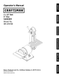
ISearsl
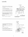
Serial
Number
Model and serial
number
may be found
at the right-hand
of the base.
side
You should record both
model and serial number
in a safe place for
future use. ,,
BE£ T AND
DISC
SANDER
Read GENERAL and
ADDITIONAL
SAFETY
o assembly
® operating
® repair parts
INSTRUCTIONS
carefully
Sold
Part No 68034
by
SEARS,
ROEBUCK
AND
CO.,
Chicago,
IL.
60684
U.S.A.
Printed InUSA
FULL ONE YEAR
If within
one year from
material or workmanship.
Warranty
service
United States
This warranty
WARRANTY
ON CRAFTSMAN
the date of purchase,
this Craftsman
Sears will repair it free of charge
is available
by simply
gives you specific
contacting
legat rights,
the
and you
Belt
nearest
BELT AND DISC SANDER
and Disc Sander
Sears store
may also have other
fails due
or Service
rights which
Center
to a defect
in
throughout
vary from
the
state to state
SEARS_ ROEBUCK
ANDCO
RSC 41-3
SEARS TOWER
CHICAGO
IL 60684
generaB
1 KNOW
safely
YOUR
POWER
insfrucfions
for power
13_ SECURE
TOOL
14_ DON'T
ALL TOOLS
This
tool
is equipped
with
an approved
3-conductor
cord and a 3-plong
grounding
type plug to fit the proper
grounding
type receptacle
Th_ green conductor
in the
cord is the grounding
wire
Never connect
the green wire
to a live terminal
3 KEEP GUARDS
- Jn working
merit
4 REMOVE
and
in proper
ADJUSTING
adjustment
Cluttered
AREA
areas
and
must not be slippery
6. AVOID
accidents
before
blades
DANGEROUS
7 KEEP CHILDREN
Atl visitors
8. MAKE
- with
keys
should
9. DON'T
It will
a safe distance
from
19,
switches,
or by removing
area
[he
job
better
and
safer at the
Don't
designed
force
or attachment
to
do
rate for which
a job
it was not
as
STARTING
is in "OFF"
position
before
plugging
ACCESSORIES
ON
TOOL
iniury
could occur if the tool
tool is accidentally
contacted
is tipped
or if the
materials
above or near the tool such
to stand on the tool to reach them
DAMAGED
21 DIRECTION
11 WEAR PROPER APPAREL
that
PARTS
OF FEED
Feed work into a blade or cutter against
_otation of the blade or cutter only
Do not wear _oose clothing,
gloves
neckties or jewelry
(rings,
wristwatches)
to get caught
m moving
parts
NONSLIP
footwear
ts recommended
Wear protective
had
covering
to contain
tong hair
Roll tong sleeves
above the elbow
GOGGLES
such
Check for alignment
of moving parts binding of moving
parts, breakage
of parts, mounting_
and any other con.
ditions
that may affect
its operation
A guard or other
part
that is damaged
should
be properly
repaired
or
reptaced
for
12 USE SAFETY
accessories
Before further
use of the tool
a guard or other part that
is damaged
should be carefully
checked to ensure that it
will operate
properly
and perform
its intended
func1_ion
TOOL
tool
STAND
20. CHECK
starter
il was designed
10 USE RIGHT
switch
Do not store
it is necessary
FORCE TOOL
do
NEVER
Serious
cutting
KID-PROOF
master
changing
ACCIDENTAL
sure
perform
changing
Consult
theowners
manual for recommended
accessories
Follow
the instructions
that accompany
the accessories
The use of improper accessories may cause hazards
or ex
Provide
work
WITH CARE
18. USE RECOMMENDED
Ftoor
AWAY
WORKSHOP
padlocks,
Make
in
ENVIRONMENT
be kept
at alt ttmes
TOOLS
serv*cmg;
when
bits cutters
etc
17, AVOID
due to wax or sawdust
Don't
use power tools in damp or wet locations
pose them to rain
Keep work area well lighted
adequate surrounding
work space
TOOLS
16. DISCONNECT
and align
CLEAN
mvite
and balance
Keep tools sharp and clean for best and safest
ance
Follow
instructions
for lubricating
and
accessories
KEYS AND WRENCHES
benches
footing
15. MAINTAIN
Form
habit
of checking
to see that keys and adjusting
w_enches are removed from tool before turning
it on
5 KEEP WORK
OVERREACH
Keep proper
IN PLACE
order
WORK
Use clamps or a vise to hold work when practical
Its
safer than using your hand frees both hands to operate
tool
Read the owner's manual carefully
Learn its application
and limitations as well as the specific potential hazards
peculiar to this tool
2, GROUND
fooUs
the direction
of
22. NEVER LEAVETOOLRUNNING
UNATTENDED
Turn
(Head Protection)
complete
Wear safety
goggles
(must
comply
w_th ANS
Z87 1)
at all times
Also
use face or dust mask if cutting opm
at_on is dusty
and ear protectors
(plugs or muffs) during
extended periods Of operatlon
2
power
stop
off
Don[
leave
toot
until
it
comes
to
a
additional safe,/instructions for
beUt and disc sander
Safety
is a combination
of operator
common
sense and
alertness
at all times when the finishing
machine
is being
used,
WARNING:
FOR YOUR OWN SAFETY, NO NOT
ATTEMPT
TO OPERATE
YOUR
FINISHING
MACftlNE
UNTIL
IT IS COMPLETELY
ASSEMBLED AND INSTALLED
ACCORDING
TO THE
INSTRUCTIONS
. . . AND UNTIL YOU HAVE
READ AND UNDERSTOOD
THE FOLLOWING.
f
Make sure the abrasive belt runs in the right direction
Always have the tracking adjusted correctly
so that the
belt does not run off the pulleys
g.
Hold the work firmly
when finishing
belt and against the worktable
when
disc
h Always adjust the worktable
abrasive disc or belt
When finishing a large piece
is supported
at table height,
PAGE
1, General Safety Instructions For Power Tools ....
2. Getting To Know Your Sander
.................
18
21
4. Maintenance
23
5.. Stability
............................
to within
1/16 in of the
of material,
make
sure it
Never leave the machine work area with the power on,
before the machine
has come to a complete
stop, or
without
removing and storing the switch key
2
3 Basic Machine Operation ..........................
on the abrasive
finishing
on the
k
Never operate the machine
with
the unused shaft end of the motor
protective
removed
cover
on
Of Machine
9. If any part of this belt disc sander should break,
or fail in any way or any electrical
component
perform
properly,
or if any is missing, shut off
switch,
remove power supply
cord from power
and replace damaged
missing and/or failed paris
If there is any tendency
for the machine
to tip over or
move during
certain
operations
such as when finishing
long heavy boards, the sander should be bolted down
resuming
bend,
fail to
power
supply
before
operation
6 Location
10
The machine should be positioned so neither the operator nor a casual observer is forced to stand in line with
the abrasive belt or disc This machine is intended for
indoor use only
Read and follow the instructions appearing on label on
the rear of the Disc Dust Trap (Disc Housing):
7. Kickback
DANGER
When finishing on the Disc, always apply the workpiece
to the "Down Side" of the disc, Applying the workpiece to the "Up Side" could cause it to fly up
(kickback) which could be hazardous
8 Protection:
FOR YOUR
OWN SAFETY:
1. READ AND UNDERSTAND
UAL BEFORE OPERATING
OWNERS
MACHINE
MAN-
2 WEAR SAFETY GOGGLES AND DUST MASK
Eyes, Hands, Face, Ears, Body
3_ KNOW HOW TO AVOID
SANDING DISC
a Wear safety goggles that comply with ANSZ87 11968, and a face shield if operation is dusty Wear
ear plugs or muffs during extended periods of operation
"KICKBACKS*"
ON
4 ALWAYS SUPPORT WORKPIECE WITH "BACK
STOP" OR "WORKTABLE"
b, Do not finish pieces of material too small to hold by
hand
c, Avoid awkward hand positions, where a sudden slip
could cause a hand to move into the abrasive disc or
belt
d.
Never climb
e.
Never turn your
Sander "ON"
before
clearing
the
table(s)
or work
surface(s)
of all objects
(tools,
scraps of wood,
etc) except for the workpiece
and
related
feed or support
devices
for the operation
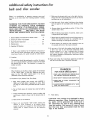
11 Think Safety.
CAUTION:
This machine is not designed for heavy
deburring operations. When finishing ferrous metals, sparks will be generated and could cause a
fire. Disconnect any type of dust collecting hose
from the machine. Also remove all traces of wood
dust that may have accumulated
inside the dust
traps in the machine.
on the machine
planned
3
additiona8 safe instructions
for beat and disc sander
WARNING:
THE 2-1/2" MACHINE PULLEY AND
THE 2" MOTOR PULLEY
FURNISHED,
WILL
RUN THE DISC AT APPROXIMATELY
2700
RPM AND THE BELT AT APPROXIMATELY
2100 (FEET PER MINUTE) WHEN USED WITH A
3450 RPM MOTOR. NEVER SUBSTITUTE
OR
INTERCHANGE
THESE PULLEYS TO INCREASE
THIS SPEED BECAUSE IT COULD BE DANGEROUS.
WEAR
WARNING:
DO NOT ALLOW
FAMILIARITY
(GAINED
FROM FREQUENT
USE OF YOUR
MACHINE)
TO BECOME COMMONPLACE.
ALWAYS REMEMBER THAT A CARELESS FRACTION OF A SECOND IS SUFFICIENT
TO INFLICT SEVERE INJURY.
YOUR
The operation of any power tool can result in foreign
objects being thrown into the eyes, which can result in
severe eye damage. Always wear safety goggles complying
with ANSI Z87.1 (shown on Package) before commencing
power tool operation. Safety Goggles are available at Sears
retail or catalog stores.
4
motor specifications and enectricaUrequirements
This power too! is equipped
with a 3-conductor
cord and
grounding
type plug which has a grounding
prong, approved
by Underwriters'
Laboratories
and the Canadian
Standards
Association
The ground conductor
has a green iacket and
is attached to the tool housing at one end and to the ground
prong in the attachment
plug at the other end
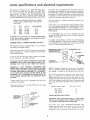
This machine is designed to use a 3450 RPM motor only
Do not use any motor that runs faster than 3450 RPM
It is wired for operation on 110-120 volts, 60 Hz,, alternating current
IT MUST NOT BE CONVERTED
TO
OPERATE ON 230 VOLTS EVEN THOUGH SOME OF
THE RECOMMENDED MOTORS ARE DUAL VOLTAGE
THESE CRAFTSMAN
MOTORS HAVE BEEN
FOUND TO BE ACCEPTABLE FOR USE ON
THIS TOOL.
HP
RPM
VOLTS
1/2
1/2
3/4
3/4
3450
3450
3450
3450
110-120
110-120
110-120
110-120
CATALOG
This
plug requires
outlet as shown
NO.
1216
1218
1219
1226
TO POWER SOURCE
This machine
must be grounded
the operator
from electric sbock,
while
Plug power cord into a 110-120V
properly
outlet
protected
by a 15-amp. time delay
fuse or circuit
breaker
type
adapter
connect
as shown
and always
the
grounding
lug
to
ground
you have a qualified
outlet
with a properly
electrician
grounded
An adapter as shown below is available for connecting
plugs
to 2-prong receptacles
The green grounding
lug_ extending
from the adapter must be connected
to a permanent
gTound
such as to a properly
grounded
outlet box
protect
MAKESURETHISIS
CONNECTED TO A
KNOWN GROUND
grounded
type
or Circuit-Saver
If you are not sure that your outlet is properly
have it checked by a qualified electrician
grounded
to use for this power tool is
NOT REMOVE
OR ALTER
iN ANY
MANNER
Use an
It is recommended
that
replace the TWO prong
THREE
prong outlet
OUTLET
in use to
3-conductor
If the outlet you are planning
of the two prong type
DO
THE GROUNDING
PRONG
known
CAUTION:
Do not use blower or washing machine motors
or any motor with an automatic
reset overload protector
as their use may be hazardous.
CONNECTING
a mating
GROUNDING
LUG
ADAPTER
3-PRONG
PLUG
grounded,
l
WARNING:
DO NOT PERMIT FINGERS TO TOUCH THE
TERMINALS
OF PLUGS WHEN INSTALLING
OR REMOVING
THE PLUG TO OR FROM THE OUTLET
2--PRONG
RECEPTACLE---'---_
WARNING:
IF NOT PROPERLY
GROUNDED
THIS
POWER TOOL CAN INCUR THE POTENTIAL HAZARD
OF ELECTRICAL SHOCK,. PARTICULAR LY WHEN USED
IN DAMP LOCATIONS IN PROXIMITY TO PLUMBING.
IF AN ELECTRICAL
SHOCK OCCURS THERE IS THE
POTENTIAL
OF A SECONDARY
HAZARD
SUCH AS
YOUR HANDS CONTACTING
THE ABRASIVE
BELT
OR DISC.
NOTE: The adapter illustrated
is for use only if you aheady
have a properly
grounded
2-prong
receptacle
Adapter
is
not allowed
in Canada by the Canadian
Electrical
Code
The use of any extension
cord will cause some loss of
power
To keep this to a minimum
and to prevent
overheating and motor burn-out,
use the table below to deter
mine the minimum
wire size (AWG)
extension
cord
Use
only
type
if power cord is worn or cut, or damaged in any way, have
it replaced immediately.
3 wire extension
cords which
plugs and 3-pole receptacles
have 3-prong grounding
which accept the tools
plug
If your unit is for use on less than 150 volts it has a plug
that looks like below
Extension
Cord
Length
Wire
Up to 100 Ft
3-PRONG
PLUG
PROPERLY
GROUNDED
OUTLETs.
u)
U]
G
16
Ft
14
200_400
Ft
10
ROTATION
WARNING:
FOR YOUR OWN SAFETY, MAKE SURE
PLUG IS NOT CONNECTED TO POWER SOURCE OUT*
LET, WHEN CHANGING MOTOR ROTATION
©
/n
AW
100_200
CHECK MOTOR
/n
Size
GROUNDING
PRONG
The
motor
must
rotate
COUNTERCLOCKWISE
when
viewed from
the shaft end to which you wil! mount
the
pulley
(See page 11) If it does not, change the direction
according
to the instructions
furnished
with
the motor
5
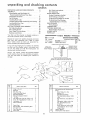
unpacking
and checking contents
CONTENTS
UNPACKING
AND
ASSEMBLY
....................................
CHECKING
CONTENTS
Motor
On-Off
Rotation
Switch
7
..........................
11
..............................
Table
13
Work
Installing
Installing
Installing
Abrasive Belt-Tensioning
and Tracking
Belt Dust Trap
.....................
Backstop
..............................
TO KNOW
Belt Adjusting
Screws
Belt Locking Screws
Work Table Tilt Lock
Backstop
Your Belt
one carton
.......................
YOUR
Lock
SANDER
15
16
17
18
............
..........................
19
19
discarding
any packing
21
21
Finishing
Finishing
22
Curved Edges on the Belt
Small End Surfaces
in
°_
Accessories
_"_°_--°
1/2"" Wrench
W16"'
3/4'
material
.............
22
23
23
23
24
.................
Wrench
TOOLS
24
NEEDED
==========
Medium Screwdriver
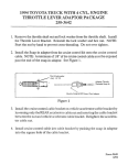
SQUARE
MUST
BE
TRUE
STRAIGHT
EDGE
OF
BOARD
3/4"
TH{CK
DRAW
LIGHT
LINE
ON BOARD
ALONG
25
27
__
COMBINATION
If any parts are missing, do not attempt
to assemble
the Belt and Disc Sander, plug in time power cord,
or turn
the switch
on until the missing parts are
obtained and installed correctly
..............
Edges on the Disc
.........................
Recommended
Separate
all parts from packing materials
and check
each item
with
illustration
and "Table
of Loose
Parts."
Make certain
all items are accounted
for,
before
21
REPAIR PARTS
.................................
PARTS LIST .....................................
20
and Disc Sander is shipped complete
(without
motor or floor base)
.............................
Wiring Diagram
......................
LUBRICATION
.......................
TROUBLE
SHOOTING
............................
19
............................
OPERATION
20
20
Surface Finishing on the Belt
.................
End Finishing
on the Belt ................
and Curved
MAINTENANCE
18
.........................
Screw
....................
Screw
Belt Table Locldng Bolts .......................
Belt Table Stop
.........................
BASIC
........
Installing
GETTING
6
7
Mounting
Belt and Disc Sander On
Recommended
Craftsman
Floor Base
Check
.....
TH_S
THI
EDGE
PERFECTLY
MUST
BE
STRAIGHT
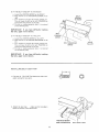
Using a 1/2" wrench•
remove the plywood
attached
to time machine
Save the nuts and bolts and washers
You will
the base
need
them
for
attaching
the
machine
to
SHOULD
SQUARE
BE NO
GAP
IS FLIPPED
OR
OVER
OVERLAP
IN
DOTTED
HERE
WHEN
POSITION
2
"r/ ..
3
5
19
18
14
16/'
17
"
Z
""-,
\ ......111
.......
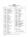
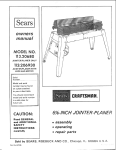
L
Key
No
Table o1 Loose Parts
1
2
3
4
5
6
7
8
9
10
11
V-Beh
1/2x4!
Backstol:
Belt, Dust Trap
.
Motor Pul ev Belt Guard
Belt Guard Suoport
.
3elt Guard SUDDOrt Bracket
'S" Clip
.
Pan Head Screw. Type 23. 10-32 x 1/2
Screw Pan Head Machine 1/4-20 x 1/2
LockwasheL
1/4Switch Assembly
3
3
2
2
i
12
13
14
15
16
Switch Keys
Baseand Belt Table
Disc Dust TraD
2
I
I
Dust Trap Cover
Work Table
(w/Sanding
Key
No
Oty
17
1
1
]
Belt)
i
i
i IB
l
I
6
1
2"'_
Table of Loose Farts
Bag (containing
the following
parts)
Motor Pulley, 2 In Din
Wrench, 1 I2"
.............
5/32 Setscrew Wrench
Flat Head Machine Screw
1-3/4
.................
Pan Head Screw, Type 23
3/8 ...............
Qty
loose
........
.........
10-32 x
1
2
1
4
8-32 x
Flat Washer 21/64 x 7/8 x 1/8
Hex. Head Machine Screw
5/16-18 x 1 ...........
Screw MPan Hd. 10-32x9/16
Lockwasher
No 10 I nt Tooth
Hange{, Cable ........
Owner's
Manual ............
Sanding Disc (w/Set Screw) ........
5
1
1
1
1
1
1
1
assembly
MOUNTING
BELT AND DISC SANDER ON
RECOMMENDED
CRAFTSMAN
FLOOR BASE
NOT SUPPLIED
IN CANADA
If you purchase
steel legs 9-22236
furnished
with steel legs
Place the machine
align
mounting
+
follow
on the base, position
instructions
as shown,
and
holes
t_J
MOTOR MOUNT
BRACKET
THIS SIDE
CARRIAGE
BOLT
2
Insert
the bolts
and position
the stiffener
3
Insert two
7/16"
long screws furnished
with
base
through
top of base and stiffener,
screw on nuts and
7/16" SCREW
tighten
4
Place a flat washer,
of the 2-1/='' bolts
a lock
from
washer and a nut
underneath,
and
on each
tighten
STIFFENEF
NUT
LOCK
FLAT WASHER
WASHER
NUT
7
J
L
L__
assembly
1/2" WRENCH
NOTE:
The abrasive
belt
at the factory
so that
during shipment
is installed
it does
not
on the machine
become
damaged
PAPER
Loosen
wrench
2
Turn
both
of
until
they
stop
screws
3
both belt LOCKING
screws,
furnished
with the machine
Slip
so that
the
belt
the belt
ADJUSTING
Retighten
the
off
idler
and
the
using
screws
two
belt
the
1/2"
as shown
LOCKING
pulley
does
not
come
_emove
the
piece
of
out
paper
4. Remove tile protective coating, that is applied at the
factory, from the belt table. Use any ordinary household type grease and spot remover.
CAUTION:
Never
volatile solvents.
NOTE:
use gasoline,
Do not apply
naptha,
or similar
highly
BELT LOCKING SCREW
(ONE ON EACH SIDE)
BELT ADJUSTING SCREW
(ONE ON EACH SIDE)
wax to the belt table
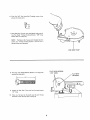
1 Loosen the belt table locking bolts behind the mounting,bracket using one of the 1/2" wrenches supplied
with your machine,
2. Position belt table vertically
the bolts
BELT TABLE LOCKING
and tighten only one of
3 Place tile V-Belt over the pulley
-"
_
RENCH
4 Attach the switch assembly to the base using the two
screws and washers packed with the switch
5 Loosen the bolt that you tightened in step 2 Position
the belt table horizontally,
and tighten both bolts
SWITCH
ASSEMBLY
8
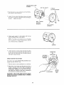
6, Find five 3/8" Pan Head Self-Treading
among the loose parts,
screws from
7 Place Disc Dust Trap on yourworkbench
and screw in
five Pan Head "Thread Cutting Screws," 3/8" long
Screw them in all the way
NOTE:
screws
thread
The holes in the Trap are not threaded
are "Thread
Cutting
Screws"
and will
but the
cut
a
as they are tightened
DISC DUST TRAP
FLAT HEAD SCREWS
1 3/4" LONG
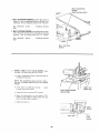
8, Find four Flat Head Machine Screws 1-3/4" long from
among the loose paris
1-3/4"
9
Attach the Disc Dust Trap with four flat head screws
1-¾" long
10
There is a flat spot on the shaft near the end Rotate
the shaft so that the flat spot is facing up
9
FLAT SPOT
ON SHAFT
assembly
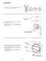
5/32INCH
_SETSCREW
._WRENCH
9
Place
the
disc
on
facing up Position
inch outward
from
10
the shaft
so that
the set screw
the disc so that it isapprox
the edge of the dust trap
is
1/16
TRAP
h_sert the long end of the 5/32"
setscrew wrench
through
the hole in the disc housing and into the
setscrew in the disc
Make sure setscrew is aligned
with "Flat"
on shaft
NOTE:
After
several hours
looseness of setscrew
of operation
and retighten
check
for
11
Remoye the two lower screws which you installed in
step 6 and loosen the other three screws
12,
]nstallthe Dust Trap cover
Tighten
and replace
the two screws
all five screws
TWO
10
LOWER
SCREWS
COVER
MOTOR BASE CLAMP
SCREWS
5/8"' DIA
SHAFT
THREAD
CUTTINGSCREWS
1 Place the motor on your workbench
shaft (with key way) facing you
2
with the 5/8 Dia
Loosen the two motor base clamp screws and rotate
the motor
so that the ventilation
holes are facing to
the side . tighten
the screws
BELT
GUARD
SUPPORT
BRACKET
3
BELT GUARD
SUPPORT
Attach guard support to the bracket with the two
screws furnished with the belt guard
NOTE:
The
but
the
screws
holes
cut
a thread
in the
are "thread
as they
bracket
cutting
are not
screws"
threaded,
and will
are tightened
SCREWS
4_ Loosen setscrew in motor pulley and place the pulley
on the shaft with the hub flush with the end of the
shaft, insert the motor shaft key and tighten setscrew
with 5/32" setscrew wrench
CHECK
MOTOR
DIRECTION
OF
ROTATION
5/32 INCH
SETSCREW
WRENCH
\
ROTATION
The motor must rotate COUNTERCLOCKWISE
viewed from the PULLEY end
when
1. Place the motor on your workbench or on the floor
2. Stand clear of the motor and plug the cord into a
properly grounded outlet (See page 5). Notice the
rotation of the pulley. If it is not turning COUNTERCLOCKWISE, REMOVE the plug from the outlet,
and change the rotation of the motor according to
the instructions furnished with the motor.
MOTOR
FLUSH HERE
WARNING:
FOR YOUR OWN SAFETY, MAKE
SURE PLUG IS NOT CONNECTED TOPOWER
SOURCE OUTLET.
11
SHAFT
KEY
assembly
1, Find four 5/16" _ 18 x 1" carriage bolts, flat washers,
lock washers and nuts supplied with base,
MOTOR
MOUNT
BRACKET
2
Insert
motor
bolts through
holes
mount
bracket
marked
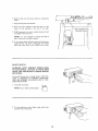
"X'"
from
_"_'/
__
_
__T_c)_;
_rX_
behind
3 Attach motor
, place a flat washer and a lock
washer on each bolt
screw on nuts but DON'T
TIGHTEN them
VENTILATION
HOLES
FACING DOWNWARD
4 Install three clips on the belt guard 90°apart
long tabs pointing AWAY from the round
5
Insert the belt into the open end of the guard
the round opening,
MAKE SURE BELT HAS NOT SLIPPED
MACHINE PULLEY
with the
opening,
and out
OFF OF
/
SPRING CLIPS
(SET 90 ° APART)
12 ¸
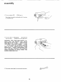
6
Place the
belt onto
the motor
pulley
by rotating
the
pulley
7
Snap the belt guard
into
position
8 Move the motor sideways so that the belt is in the
center of the opening in the top of the base
9 PUSH downward on motor
and tighten motor bolt nuts
to apply tension to belt
NOTE:
It is only necessary to tension
that it does not slip while running
10
the belt so
If you cannot obtain sufficient tension with the motor
pushed all the way down, remove the four motor
bolts and insert them in the LOWER set of holes
ON-OFF
SWITCH
WARNING:
DON'T CONNECT POWER CORD
TO ELECTRICAL
OUTLET
IN YOUR SHOP
UNTILYOU
ARE READYTO
CHECK MOTOR
ROTATION.
The On-Off Switch has a locking feature. THIS FEATURE tS INTENDED
TO PREVENT
UNAUTHORIZED AND POSSIBLE HAZARDOUS
USE BY CHILDREN AND OTHERS
KEY
1, Insert key into switch
2
NOTE:
Key is made of yellow plastic
To turn
and pull
machine on, insert
end of switch out
finger
under
switch
lever
13
assembly
3
To turn
Never
machine
OFF
leave the machine
to a complete
. PUSH
unattended
lever
until
in
it has come
stop
4 To lock switch in OFF position
hold switch IN
with one hand
, REMOVE key with other hand
_
WARNING:
FOR YOUR OWN SAFETY, ALWAYS LOCK THE SWITCH "OFF"
WHEN
MACHINE
IS NOT IN USE .+. REMOVE KEY
AND KEEP IT IN A SAFE PLACE + ,, . ALSO
• + + IN THE EVEN'[" OF A POWER FAILURE
(ALL
OF YOUR
LIGHTS GO OUT) TURN
SWITCH OFF.+. LOCK ITAND REMOVE THE
KEY. THIS WILL PREVENT THE MACHINE
FROM STARTING
UP AGAIN
WHEN THE
POWER COMES BACK ON.
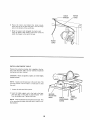
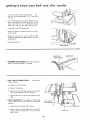
5 Find plastic cable hanger from among the loose parts+
14
HOLD_
CABLE
IANGER
6
Route
the motor
cord behind
the motor
mount,
across the top of the base and plug it into the receptacle in the bottom
of the switch box
7
Bring the power cord alongside
the motor
wrap the plastic cable hanger around the
attach the hanger to the top of the base
MOTOR
CORD
cord
cords and
POWE R
CORD
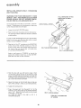
INSTALLING
WORK TABLE
Remove the protective coating, that is applied at the factory, from the work table Use any ordinary household
type grease and spot remover
CAUTION:
Never use gasoline,
volatile solvents
NOTE:
will help
the work
1
Loosen
Apply
prevent
acoat
rust
naptha,
or similar
of paste wax to the work
and make
the table positioning
it a little
table
highly
This
easier to feed
screw
2 Insert the table support rod in the hole in the base
until the edge of the table is approximately
1/16"
from the abrasive disc. Tighten the screw,
SECOND
MOUNTING
HOLE
NOTE: There isa second mounting hole in the base This
is for mounting the table when the belt is used in a vertical position
15
TABLE
POSITIONING
SCREW
TABLE
SUPPORT
ROD
assembly
INSTALLING
ABRASIVE
AND TRACKING
BELT-TENSIONING
WARNING:
FOR YOUR OWN SAFETY, TURN
SWITCH "OFF"
AND REMOVE PLUG FROM
POWER SOURCE OUTLET BEFORE REMOVING OR INSTALLING
ABRASIVE
BELT°
On the smooth
al arrow"The
so that
side of tile belt you will find a "directionbelt must run in the direction
of this arrow
the splice
does not come apart
1
Loosen
the two belt
2
Place the belt over the pulleys
row pointing
on both
Turning
pu!ley
3
LOCKING
as shown
with
the
wrenches
ply a little
BELT
ADJUSTING
SCREWS
of the belt while
BELT
of TENSION
with
your
pushing
left
the
to
hand
to
tension
belt
keep
asmall
turn
LOCKING
by
the TEN-
it from
belt in the direction
screws simultaneously
more
the
you, so that
wrenches
If the belt slips over the pulleys,
JUSTING
is moved
on the ADJUSTING
you "get the feel
amount
disc
while
pulley
(TENSIONING)
a small
turning
cause the idler
the idler
pulling
the wrenches
toward
StON feels the same on both
arrow
ar-
the wrenches
toward
you
This will
Move the wrenches back and fortha
so that
it is stretching
4_ Hold
the directional
on the belt
of the 1/2"
and pull
the belt
times
Apply
screws
screws will
When
it puts TENSION
Place both
few
ARROW_
pulleys
the belt ADJUSTING
screws
stretch
DIRECTIONAL
Make sure the belt is centered
to move in or out
outward,
PULL WRENCHES IN THIS
DIRECTION TO APPLY
TENSION
of the
both
amount
ADto ap-
to the belt
5 Adjust the tension so that the belt does not slip very
easily when pushing it, while you are holding the disc
6 Tighten the locking screws
7
Plug in the power cord
machine
run for about
Turn the switch "on",
let the
three to five seconds and then
turn it "off"
Notice if the belt while
to the right or to the left.
If
it did
not move
to the right
TRACKING
properly
running,
or
left,
moved
it
BELT
LOCKING
SCREW
is
PUSH BELT
OF ARROW
16
IN DIRECTION
SCREW
8 IF THE BELT RUNS OFF TO THE RIGHT:
a
b,
Loosen the LOCKING
SCREW on the RIGHT
Place wrench on the ADJUSTING
SCREW on the
c
right
Torn switch
on and pull the wrench toward
This will move the belt to the left
PUSHING
d
wrench will move the belt to the right
The belt is tracking
properly
when it is centered
on the DRIVE
pulley
IMPORTANT:
the belt, apply
If you have difficulty
more tension,
BELT
MOVING
TO RIGHT
you
the
tracking
BELT
LOCKING
9 IF THE BELT RUNS OFF TO THE LEFT:
SCREW
a
b
Looseo the LOCKING
SCREW on time LEFT
Place wrench on the ADJUSTING
SCREW on the
left
c
Turn switch
on and pull the wrench toward
This will move the belt to the right PUSHING
wrench will move time belt to time left
d
Time belt is tracking
properly
on time DRIVE
pulley
when
IMPORTANT:
If you have difficulty
the belt, apply more tension.
INSTALLING
BELT
you
the
DRIVE
PULLEY
ADJUSTING
SCREW
it is centered
tracking
BELT DUST TRAP
©
1 Find one 10 - 32 x 9/16" Pan Heed screw and a lockwasher among the loose parts
2 Attach the dust trap .... make sure the top edge is
below the surface of the abrasive belt
PAN HEAD SCREW
AND LOCKWASHER
17
BELT DUST TRAP
assembay
BACKSTOP
LOCK
INSTALLING
BACKSTOP
SCREW
BACKSTOP
1 Find one 5/16" x 1" Hex. Head bolt and one flat
washer among the loose parts
2, Place the washer on the bolt, and screw it halfway
into the mounting hole Place the backstop into postion and tighten the bolt When removing the backstop, loosen the bolt but do not remove it,
geffing to know your bent and disc sander
WARNING:
FOR YOUR OWN SAFETY TURN
SWITCH "OFF"
AND REMOVE PLUG FROM
POWER SOURCE OUTLET BEFORE MAKING
ANY ADJUSTMENTS.
ABRASIVE
DISC
4
BELT ADJUSTING
BACKSTOP
BACKSTOP
SCREW
(ONE ON EACHSIDE)
LOCK
SCREW
WORK
TABLE
3
WORK
TILT
TABLE
LOCK
SCREW
6
BELT
TABLE
2
BELT
STOP
LOCKING
IDLER
PULLEY
SCREW
(ONE
18
ON EACH
SIDE)
BELT
ADJUSTING
SCREW
(ONE
1, BELT ADJUSTING
SCREWS cause the idler pulley to
move in or out for applying tension to the belt or for
tracking it They are adjusted using the 1/2" wrenches
See "Assembly"
Belt"
section
....
"Installing
ON EACH
SIDE)
\
Abrasive
2, BELT LOCKING SCREWS lock the adjust ment mechanism after the abrasive belt is tensioned and tracking
properly
They are locked using the 1/2" wrench_
See "Assembly"
Belt"
section
......
"Installing
Abrasive
BELT LOCKING
SCREW
3
WORK
the table,
a
TABLE
TILT
It is locked
LOCI(
SCREW
using the 1/2"
Using a combination
square,
the table with the disc
locks
wrench
check
the angle of
NOTE:
The combination
square must be "true"Sea start of assembly section on Pg. 6 for checking
method
b
If time table is not 90 ° with
tilt lock screw and tilt table
the disc
c
Loosen
d
Screw time stop screw in or out, using
wrench so that when the table touches
screw, the table is 90 ° to time disc
e
Tighten
the lock nut using a 7/16"
loosen
wrench
TABLE
POSt'f
LOCK
SCREW
IONtNG
a 7/16"
the stop
.
I
j'--
the lock nut
I L )?)1 SCREW
- -iz 2--J
LOCI(
NUT
t
T,LT
LOCi(
SCREW
19
getting to know your beat and disc sander
f
Loosen the table positioning
tion
the table approximately
the disc
lock screw
1/16"
away
posifrom
g
Tilt the table downward
but don't tighten the loci{
screw, and position
it as close to the disc as possible. Using the head of a combination
square,
check
the angle
of the table
with
the disc
h If the table is not 45 ° with the disc:
Raise the table and loosen the lock nut using a
7/16" wrench
Screw the stop screw in or out, using a 7/16"
wrench so that when the table touches it, it is 45 °
with the disc
o
k
Tighten
the lock
nut
BACKSTOP
BACKSTOP
LOCK
4. BACKSTOP LOCK SCREW
locks the backstop
place It is locked using the 1/2" wrench
6 BELTTABLE
table
SCREW
\
in
LOCKING BOLTS ..... lock the belt
in position
To adjust
to vertical
the
position:
a
Remove
b
Loosen the two belt
1/2" wrench supplied
c
Position
bolts
belt
backstop
table
table
with
vertically
locking
bolts using
your machine
and
6, BELTTABLE STOP
table
is level
with
can be adjusted
the floor when
tighten
the
the two
so that the belt
in a horizontal
BELT TABLE
LOCKING BOLT
position
a
Loosen
the lock
nut using a 3/4"
wrench
b
Place a level on the belt table and using a 3/4"
wrench,
screw the stop bolt
in or out until the
table is level.
STOPBOLT
LOCK
2O
NUT
basic
operation
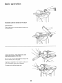
SURFACE
FINISHING
ON THE BELT
\
FLAT SURFACES
Hold the work piece firmly with
fingers away from the belt
Keep
the end butted
work
evenly
ishing very thin
For finishing
Apply
enough
pressure
If the belt
FINISHING
It is more
pieces with
Move
a miter
Use extra
and move
caution
when
your
the
fin-
pieces
stalls
ON
the backstop
to allow
the belt to remove
and the belt pulleys
applying moderate pressure
quires more tension
END
the backstop
belt
long pieces, remove
only
material
against
across the
both hands, keeping
to the worl<piece,
THE
slip while
the belt re
BELT
convenient
to finish
the ends of long workthe belt in a vertical position,
the work
evenly
across the belt
For accuracy,
use
gauge
The table may he tilted
for beveled
work
See Getting
To Know Your Finishing
Machine
for
adjusting
the
belt
table
and the work
section
table
21
basic operation
FINISHING
CURVED
CURVED
EDGES ON THE BELT
EDGES
Finish outside curves on the belt table and inside curves
on the idler pulley
FINISHING SMALL END SURFACES
CURVED EDGES ON THE DISC
AND
Move the work across the "Down Side" of the face of the
disc For accuracy, use a miter guage.
Applying the workpie'c'e to the "Up Side" could cause it
to fly up (kickback) which could be hazardous,
The table may be tilted for beveled work,
22
maintenance
WARNING:
FOR YOUR OWN SAFETY, TURN
SWITCH "OFF"
AND REMOVE PLUG FROM
POWER SOURCE OUTLET BEFORE ADJUSTING,
MAINTAINING,
OR
LUBRICATING
YOUR FINISHING
MACHINE.
Keep
your
traps
around
machine
the disc ancl the belt are designed
most
of
fine
the
Home-N-Shop
and your wolkshop
dust
Vac
They
for
should
most
clean
The dust
dust
cord
is worn
have it replaced
removal
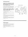
MOTOR
motor
motor
or damaged
in any
out
maintenance,
(_]
GREEN
dust that
may accumulate
POWER
CORD
follow
instructions
furnished
m
Jubrication
The BALL BEARINGS in this machine are packed with
grease at the factory They require no further lubrication
Periodically
lubricate
the cams and
pulley mechanism
with Silicon Spray
lubrication,
Cap, Flag
Terminal
BLACK
any
Do not apply wax to the belt table because the belt
could
pick up the wax and deposit
it on the pulleys,
causing the belt to slip
motor
motor
SWITCH
wav.
A coat of automobile-type
wax applied to the worktable
will help prevent rust and make it a little easier to feed
the work while finishing
For
with
Insulated
OUTLET
immediately
Frequently
blow
inside the motor
For
with
or cut,
WHITE
WHITE
to a
WARNING:
DO NOT ATTACH
A HOME-NSHOP VAC WHEN
FINISHING
IRON
OR
STEEL. THE SPARKS COULD
IGNITE THE
DEBRIS AND CAUSE A FIRE.
If power
DIAGRAM
to deflect
be connected
efficient
WIRING
follow
shafts
instructions
in the
idler
furnished
23
m
troubBe shooting
WARNING:
FOR
SWITCH "OFF"
POWER SOURCE
SHOOTING YOUR
YOUR OWN SAFETY, TURN
AND REMOVE PLUG FROM
OUTLET BEFORE TROUBLE
SANDER.
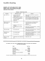
TROUBLE
PROBABLE
TROUBLE
Motor will not run.
1 Defective On-Off
Defective switch
Defective switch
2. Motor protector
SHOOTING
CHART
CAUSE
REMEDY
switch
cord
box receptacle_
open, (only if
2
your motor is equipped with an
over load protector).
Other cause,.
Machine slows down
when finishing.
2.
3
Abrasive Belt Slips
1,
Abrasive Belt tuns
off pulleys,
V-Belt too loose,
1
Applying too much pressure to
workpiece
Too much tension on abrasive
belt_
2 Ease up on pressure
3.
Adjust tension, see Assembly Section, "Installing
and Adjusting Abrasive Belt."
Not enough tension
t
Adjust tension, see Assembly Section, "Installing
and Adjusting Abrasive Belt."
Not tracking properly
1 Adjust tracking, see Assembly Section, "Installing
and Adjusting Abrasive Belt."
2. Adjust tension, see Assembly Section, "Installing
and Adjusting Abrasive Belt."
2, Not enough tension.
Wood burns while
finishing,
Abrasive disc or belt is glazed with
sap_
...................
RECOMMENDED
IN CANADA,
Replace defective parts before using belt disc
sander again,.
Consult Sears Service. Any attempt to repair this
motor may create a HAZARD unless repair is
done by a qualified service technician Repair
service is available at your nearest Sears Store
SEE YOUR
LOCAL
1,
Increase belt tension, see Assembly Section,
"Motor Pulley Belt Guard and Motor
Installation."
Replace disc or belt.
ACCESSORIES
_
SIMPSONS-SEARS STORE OR CATALOG
SELECTION AND NUMBERS
ITEM
_
FOR ACCESSORY
CAT. NO,
Floor Stand
..................................
9-22213
Miter Gauge ....................................
9_29929
Stick Disc Cement ..........................
9-2219
Abrasive Belts and Disc ...................
SEE CATALOG
Steel Legs .......................................
9-22236
Stop Rods
........................................
9-29924
Power Tool Know How Handbooks .........................
Radial Saw .....................................
9-2917
Table Saw ....................................
9-2918
The above
recommended
accessories
are current
and were available
24
at the time
this manual
was printed,,
,
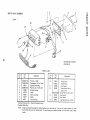
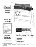
SWITCH
BOX
2
ASSEMBLY
3
/
Q
mo
I
2
2
\
5
SEE WIRING DIAGRAM
ON PAGE 23
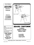
PARTS
Key
No.
Part
No.
1
2
3
4
5
6
7
8
9
STD541110
STD551210
68011
STD601103
60269
62376
60267
60317
60271
Description
LIST
Key
No.
*Nut Hex,, 10-32
*Lockwasher, 10, Int. Tooth
10
"Bracket Switch Mtg,
*Pan Hd. Scr., 10-32 x 3/8
11
12
Bracket Housing
Outlet
Part
Description
No.
37818
•67023
60256
60287
Relief,
Strain
Relief,
Strain
Key, Swltch
*Screw
6-32x
Switch, Locking
Washer
13
°STD510603
60316
°67022
Cord with Plug
t4
63467
*Screw
Nylon
Pan Hd.,
5/16
Pan Hd., 6-32 x 3/8
Box. Switch
Box, Switch
Cap Flag Terminal,
Insulator
• Standara Hardware Item - May Be Purchased Locally.
= Canadian Model Only
NOTE:
Shipping and handling charges for standard hardware items (identified by *) such as nuts. screws, washers, etc., make
buying these items bv mail uneconomical. To avoid shipping and handling charges, you may obtain most of these
locally.
Q
,=_
CRAFTSMAN BELT AND DISC SANDER
MODEL NO. 113.22521
=O
Q
25
24
20
19
4
26
_o
=O
Q
15
2
U=D
19
8
7
I
19
J
33!
55
SWITCH
58
BOX
ASSEMBLY
o_
65
44
47
63
51
62
61 60
67
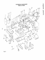
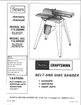
Figure 2
PARTSLiST
CRAFTSMAN
BELT
AND
DISC SANDER
FIGURE
Key
No.
"4
Part
No.
1
2
3
4
38834
68033
STD503103
30646
5
6
7
STD600803
68003
133656
8
9
10
11
12
13
14
15
16
17
18
19
20
21
22
68004
68013
STD580025
38812
STD523115
STD551131
68005
STD551031
47218
37158
STD315228
STD523112
47222
47190
STD502502
23
24
25
26
27
28
29
30
STD315228
68006
STD551210
STD511105
68014
STD551037
68007
STD510605
31
32
33
34
35
68008
47815
68009
68010
STD510803
1Disc, 9 inch Abrasive
Disc, Sanding (w/Set Screw)
*Screw. Socket Head Set, 5/16-18 x 5/16
tPulley (w/Set Screw) 2-1/2 dia. x 1/2,
"V" Groove 5/8 bore, Keyed
*Screw, Type 23, Pan No. 8-32 x 3/8
Cover, Housing
*Screw, Machine Fiat Head No. 10-32
x 1-3/4
Housing, Disc
Shaft, Drwe
Key, Woodruff, No. 9
Key, Woodruff
*Screw, Hex Head 5/16-18 x 1-1/2
* Lockwasher. 5/16
Bracket, Mounting
*Washer. 21/64 x 7/8 x 1/8
Bracket, Table Support
Ring, Retaining 5/8
Bearing, Ball
*Screw, Machine Hex Head 5/16-18 x 1-1/8
Backstop
Pulley, Drive (w/Set Screw)
*Screw, Socket Head Set, 1/4-20
x 5/16
Bearing Ball
Trap, Dust
* Lockwasher No. 10 Int. Tooth
*Screw Mach. Pan Hd. 10-32 x 9/16
Table, Belt
*Washer, 3/8 x 3/4 x 1/16
Nut, Cam
*Screw. Machine Pan Slotted
No. 6-32 x 7/16
Cam, Left Hand
Spring
Cam, Right Hand
Guard, Idler
*Screw, Machine Pan Head
No. 8-32 x 3/8
1
• Standard
t Stock
Catalog
Hardware
Item
Item
- May Be Purchased
- May be secured
Order
Houses.
through
NO. 113.22521
PARTS LIST
Key
No,
Descrtpnon
MODEL
Part
No.
36
37
38
39
47813
60254
60253
STD601105
40
41
42
43
60255
60252
STD304410
62023
44
47622
45
STD571807
46
38538
47
38536
48
68015
49
47621
50
60096
51
47414
52
68017
53
STD522505
54
STD551125
55
100167
56
STD541250
57
STD523107
68-$ZJ3523322
68016
60
STD541025
61
STD522512
62
38738
63
9414427
65
66
67
Description
tBelt, Sanding
Bracket, Support
Support, Belt Guard
*Screw, Type 23 Pan Head
No. 10-32 x 1/2
"S" Clip
Guard, Belt
IV-Belt, 1/2 x 41"
¢Pulley, (w!Set Screw) 2" Dia. x 1/2
"V" Groove 5/8 Bore
Shaft, Control
Pin, Roll 3/16 x 5/8
Ring, Retaining 5/8
Bearing, Ball
Base
Shaft, Idler
*Wrench Hex.. 5/32
Pulley, Idler
Wrench
*Screw, Machine Pan Head 1/4-20 x 1/2
* Lockwasher. 1/4
*Bolt, Hex. Head. I/2-13 x 4-1/2
"Nut, Hex., I/2-13
Bolt, High Strength, 5/16-18 x 3/4
BoJ_..l_Jgl__18
x 2-1/4
_Support Assembly, Base
*Nut, Hex. 1/4-20
*Screw, Machine Hex. Head, 1/4-20 x1-1/4
Bracket, Table Lock
*Screw, Sems 5/16-18 x 1/2
Hex. Head
38539
47219
68036
Pin
Table,
68034
68035
Owner's Manual
(Not Illustrated)
Bag of Loose Parts (Not Illustrated)
Hanger,
Work
Cable
Locally.
the Hardware
Department
of most Sears or Simpsons-Sears
Retail
Stores
or
iSearsl
owners
BEi T AND
DISC
SANDER
manual
SERVICE
Now
that
Sander
113.22521
purchased
a need
ever
or service,
simply
contact
and
Sears,
Roebuck
most
all pertinent
The
model
number
will
be found
WHEN
GIVE
PART
parts
Service
you
Sold
Part No 68034
by
SEARS,
ROEBUCK
attached
parts
Center
you call or visit.
to your
saw, at
PARTS,
NUMBER
PART
DESCRIPTION
NAME
OF ITEM
Belt And
listed
may
and
are not
be ordered
most
stocked
from
locally,
Parts Distribution
Center
Form No, SP4000-9
Disc Sander
any
Sears
Sears s_ores° If the parts
transmitted
CO.,
ALWAYS
INFORMATION:
be electronically
AND
repair
Disc
Belt and Disc Sander
REPAIR
NUMBER
Center
need
&
side of the base.
113.22521
All
for
Belt
Co. stores.. Be sure
facts when
FOLLOWING
MODEL
exist
and
of your
ORDERING
THE
your
any Sears Service
on a plate
the right-hand
HOW TO ORDER
REPAIR PARTS
have
should
to provide
MODEL NO.
you
to
your
order
a Sears
will
Repair
for handling..
Chicago,
IL.
60684
U.S.A.
Printed in U.,S.A_ 9/77