1
Operator s Manual
®
LAWN TRACTOR
19.5 HP, 42" Deck
Electric Start, 7 Speed
Model
No. 247:28902
• Espanol,
P. 59
This product has a low emission engine which operates differently
from previously built engines. Before you start the engine, read and
understand this Operator's Manual.
Before using this equipment,
read this manual and follow
all safety rules and operating
instructions.
Sears Brands Management
Corporation,
For answers to your questions about
this product, Call:
1-800-659-5917
CraftsmanTractorHelpLine
7 am - 7 pm CT, Mon.- Sun.
Hoffman Estates, IL 60179 U.S.A.
Visit our website: www.craftsman.com
FormNo.769-05571A
(February
15,2010)
Warranty Statement .......................................................... 2 Off-Season Storage ,.,.,........ ,..,........... :...................... "... 27
Safety Instructions ............................................................ 3 Troubleshooting ............................................................... 28
Slope Gauge ..................................................................... 8 Labels ............................................................................. 29
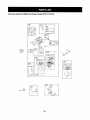
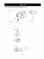
Safety Labels .................................................................... 9 Parts List ......................................................................... 30
Assembly ......................................................................... 10 Espa_ol ............................................................................. 59
Operation ........................................................................ 12 Service Numbers .......................................... ,.,Back Cover
Service and Maintenance .............................................. 18
CRAFTSMAN
FULL WARRANTY
Whenoperated
andmaintained
according
toall supplied
instructions,
ifanynon-expendable
partofthisridingequipment
failsduetoa defectin
materialorworkmanship
withintwoyearsfromthedateorpurchase,
call1-800-659-5917
toarrangeforfreein-home
repair.
Theframeandfrontaxlewillbe repaired
freeofcharge
for fiveyearsfromthedateofpurchase
ifdefective
inmaterial
orworkmanship.
Alloftheabovewarranty
coverage
appliesforonly90 daysfromthedateofpurchase
ifthisriding
equipment
iseverusedfor commercial
or
rentalpurposes.
Inallcases,if repairproves
impossible,
theridingequipment
willbereplaced
freeofchargewiththesameoranequivalent
model.
Thebatterywillbereplaced
freeofchargefor90 daysfromthedateofpurchase
ifdefective
inmaterial
orworkmanship
(ourtesting
proves
thatit
willnotholda charge).
ThiswarrantycoversONLYdefectsin materialandworkmanship.
SearswillNOTpayfor"
•
Expendable
itemsthatbecomewornduringnormaluse,includingbutnotlimitedto blades,sparkplugs,air cleaners,belts,
andoil filters.
•
•
•
•
Standardmaintenance
servicing,oil changes,or tune-ups.
Tirereplacement
or repaircausedbypuncturesfromoutsideobjects,suchasnails,thorns,stumps,or glass.
Tireor wheelreplacement
or repairresultingfromnormalwear,accident,or improperoperationor maintenance.
Repairsnecessarybecauseof operatorabuse,includingbutnotlimitedtodamagecausedbytowingobjectsbeyondthe
capabilityofthe ridingequipment,
impactingobjectsthat bendtheframeor crankshaft,orover-speeding
theengine.
Repairsnecessarybecauseof operatornegligence,includingbutnotlimitedto, e ectrcalandmechanicadamagecaused
byimproperstoragefailuretousethepropergradeandamountof engineoil,failuretokeepthedeckclearof flammable
debris,or failureto maintaintheridingequipmentaccordingto theinstructionscontainedin theoperator'smanual.
Engine(fuelsystem)cleaningor repairscausedbyfueldeterminedto becontaminated
or oxidized(stale).Ingeneral,fuel
shouldbe usedwithin30 daysof its purchasedate.
Normaldeteriorationandwearof theexteriorfinishes,orproductlabelreplacement.
•
•
•
Thiswarrantyappliesonlywhilethisproductis withintheUnitedStates.
Thiswarrantygivesyouspecificlegalrights,andyoumayalsohaveotherrightswhichvaryfromstatetostate.
SearsBrandsManagementCorporation,HoffmanEstates,IL 60179
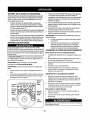
GrossHP:
Engine Oil:
Fuel:
19.5
SAE 30
Model Number
Unleaded Gasoline
Date of Purchase
Spark Plug:
Champion® RC12YC
Engine:
Briggs & Stratton intekTM
© KCDIR LLC
Serial Number
Record the model number,serial number,
and date of purchaseabove.
2
Thissymbolpointsoutimportantsafetyinstructions
which,if not
followed,couldendangerthepersonalsafetyand/orpropertyof
yourselfandothers.Readandfollowall instructionsin thismanual
beforeattemptingto operatethis machine.Failuretocomplywith
theseinstructionsmayresultin personalinjury.Whenyouseethis
symbol,HEEDITSWARNING!
•"
Thismachinewas builttobe operatedaccordingtothesafeoperationpracticesin thismanual.Aswithanytypeof powerequipment,
carelessness
or erroron thepartof theoperatorcanresultin serious
injury.Thismachineis capableof amputating
fingers,hands,toes
andfeetandthrowingdebris.Failureto observethefollowingsafety
instructionscouldresultin seriousinjuryor death.
CALIFORNIA
PROPOSITION
65
Your Responsibility--Restricttheuseofthispowermachineto
persons
whoread,understand
andfollowthewarnings
andinstructionsinthismanualandonthemachine.
EngineExhaust,someof itsconstituents,
and certainvehicle
componentscontainor emitchemicalsknowntoStateof California
tocausecancerandbirthdefectsor otherreproductive
harm.
Batteryposts,terminals,and relatedaccessories
containleadand
leadcompounds,
chemicalsknowntothe Stateof Californiato
causecancerand reproductive
harm.Washhandsafterhandling.
SAVE THESE
INSTRUCTIONS!
IIIIIIII I
GENERAL OPERATION
•
•
•
•
•
•
•
Read,understand,
andfollowallinstructions
onthemachineand
inthemanual(s)beforeattempting
toassemble
andoperate.
Keepthismanual
ina safeplaceforfutureandregular
reference
andforordering
replacement
parts.
Befamiliarwithallcontrolsandtheirproperoperation.
Knowhow
tostopthemachineanddisengagethemquickly.
Neverallowchildrenunder14yearsoldtooperate
thismachine.
Children14yearsoldandovershouldreadandunderstand
the
operation
instructions
andsafetyrulesinthismanualandshould
betrainedandsupervisedbya parent.
Neverallowadultstooperate
thismachinewithout
proper
instruction.
Tohelpavoidbladecontactor a thrownobjectinjury,keep
bystanders,
helpers,childrenand petsatleast75feetfromthe
machinewhileit is in operation.Stopmachineif anyoneenters
thearea.
Thoroughlyinspecttheareawheretheequipmentis tobe used.
Removeall stones,sticks,wire,bones,toys,and otherforeign
objectswhichcouldbe pickedup andthrownbythe blade(s).
Thrownobjectscancauseseriouspersonalinjury.
Planyourmowingpatternto avoiddischargeof materialtoward
roads,sidewalks,
bystandersandthelike.Also,avoiddischargingmaterialagainsta wallor obstructionwhichmaycause
dischargedmaterialto ricochetbacktowardtheoperator.
•
Alwayswear safety glasses or safety goggles during operation
and while performingan adjustment or repairto protect your eyes.
Thrown objects which ricochet can causeserious injury to the
eyes.
•
Wear sturdy, rough-soledwork shoesand close-fittingslacks and
shirts. Loose fitting clothesand jewelry can be caught in movable
parts. Never operate this machine in bare feet or sandals.
•
Be aware of the mowerand attachment discharge direction and
do not point it at anyone. Do not operate the mower withoutthe
discharge cover or entire grass catcher in its proper place.
•
Do not put hands or feet near rotating parts or under the cutting
deck. Contact with the blade(s) can amputate handsand feet.
•
A missing or damaged discharge cover can causeblade contact
or thrown object injuries.
•
Stopthe blade(s) when crossing gravel drives, walks,or roads
and whilenot cutting grass.
•
Watch for traffic when operating near or crossing roadways.This
machineis not intendedfor use on any public roadway.
Do not operate the machine while under the influence of alcohol
or drugs,
•
3
•
•
Mowonly in daylight or good artificial light.
Nevercarry passengers.
•
Disengageblade(s) before shiftinginto reverse. Back up slowly.
Always look down and behind before and whilebacking to avoid a
back-overaccident.
•
•
•
Neverleavea runningmachineunattended.
Alwaysturnoff
blade(s),set parkingbrake,stopengineandremovekeybefore
dismounting.
•
Useextracarewhenloadingor unloadingthemachineintoa
traileror truck.Thismachineshouldnotbedrivenupor down
ramp(s),becausethemachinecouldtip over,causingserious
personalinjury.Themachinemustbe pushedmanuallyon
ramp(s)toloador unloadproperly.
Mufflerandenginebecomehotandcancausea bum.Donot
touch,
•
•
•
Disengage all attachment clutchesand depress the brake pedal
completely before attemptingto start engine.
•
Your machine is designedto cut normal residential grass of a
height no more than 10". Donot attempt to mow through unusually
tall, dry grass (e.g., pasture)or piles of dry leaves.Dry grass or
leaves may contact the engine exhaust and/or build up on the
mower deck presentinga potentialfire hazard.
Useonly accessories and attachmentsapproved for this machine
by the machine manufacturer.Read,understand and follow all
instructions provided withthe approvedaccessory or attachment.
For a list of approved accessoriesand attachments,call 1-800659-5917.
•
Data indicates that operators, age 60 years and above, are
involved in a large percentage of riding mower-relatedinjunes.
These operators should evaluatetheir ability to operate the riding
mower safely enough to protectthemselvesand othersfrom
serious injury.
Foryoursafety,usetheSlopeGuideincludedaspartofthismanual
to measureslopesbeforeoperatingthis machineon a slopedor hilly
area.If theslopeis greaterthan15degreesas shownon theSlope
Guide,do notoperatethismachineon thatareaor seriousinjurycould
result.
•
Check overhead clearancescarefully before driving under low
hanging tree branches, wires, door openings etc., where the
operator may be struckor pulledfrom the machine,which could
result in serious injury.
,
Slopesarea majorfactorrelatedtolossofcontrol
andtip-over
accidents
whichcanresultinsevereinjuryordeath.Allslopes
require
extracaution.
Ifyoucannotbackuptheslopeorifyoufeeluneasyon
it, do notmowit.
Do:
•
•
SLOPE OPERATION
Slowdownbeforeturning.Operatethemachinesmoothly.Avoid
erraticoperationandexcessivespeed.
Disengageblade(s),set parkingbrake,stop engineandwaituntil
theblade(s)cometo a completestopbeforeremovinggrass
catcher,emptyinggrass,uncloggingchute,removinganygrassor
debris,or makinganyadjustments.
•
•
Useslowspeed.Choosea lowenoughspeedsettingsothat
youwillnothaveto stopor shiftwhileon theslope.Tiresmay
Fosetractionon slopeseventhoughthe brakesarefunctioning
properly.Alwayskeepmachinein gearwhengoingdownslopes
to takeadvantageof enginebrakingaction.
Followthemanufacturer's
recommendations
forwheelweights
or counterweights
to improvestability.Forrecommendations,
call
1-800-659-5917.
•
Useextracarewithgrasscatchersor otherattachments.
These
canchangethestabilityof themachine.
•
Keepallmovementon theslopesslowandgradual.Donotmake
suddenchangesin speedor direction.Rapidengagement
or
brakingcouldcausethefrontof themachineto lift andrapidlyflip
overbackwardswhichcouldcauseseriousinjury.
•
Avoidstartingor stoppingon a slope.Iftireslosetraction,disengagethe blade(s)and proceedslowlystraightdowntheslope.
Do Not:
•
•
If situations occur which are not covered inthis manual, use care
and good judgment. Contact 1-800-659-5917for informationand
assistance.
Mowupanddownslopes,notacross.Exerciseextremecaution
whenchangingdirectionon slopes.
Watchforholes,ruts,bumps,rocks,or otherhiddenobjects.
Uneventerraincouldoverturnthemachine.Tallgrasscanhide
obstacles.
Do not turn on slopes unless necessary; then,turnslowlyand
graduallydownhill, if possible.
Do not mow near drop-offs, ditches or embankments.The mower
could suddenly turn over if a wheel is over the edge of a cliff,
ditch, or if an edge caves in.
•
Do not try to stabilize the machine by putting your foot on the
ground.
•
Do not use a grass catcher on steep slopes.
•
•
Do not mow on wet grass. Reduced traction could cause sliding.
Donot attempt to coast downhill. Over-speedingmay causethe
operator to lose control of the machine resultingin serious injury
or death.
Do not tow heavy pull behind attachments (e.g. loaded dump cart,
lawn roller, etc.) on slopes greater than 5 degrees. When going
down hill, the extra weight tends to push the tractor and may
causeyou to loose control (e.g. tractor may speed up, brakingand
steeringability are reduced, attachment may jack-knife and cause
tractor to overturn).
4
CHILDREN
SERVICE
Tragicaccidentscanoccuriftheoperatoris notalerttothepresence
of children.Childrenare oftenattractedtothe machineandthemowing
activity.Theydo notunderstandthedangers.Neverassumethat
childrenwill remainwhereyoulast sawthem.
•
Keepchildrenoutof themowingareaandin watchfulcareof a
responsibleadultotherthantheoperator.
•
Bealertandturnmachineoff if a childentersthearea.
•
Beforeand whilebacking,lookbehindanddownfor small
children.
SafeHandlingof Gasoline
Toavoidpersonalinjuryor propertydamageuseextremecarein
handlinggasoline.Gasolineis extremelyflammableandthevaporsare
explosive.Seriouspersonalinjurycanoccurwhengasolineis spilled
onyourselfor yourclotheswhichcanignite.Washyourskinand
changeclothesimmediately.
•
Useonlyanapprovedgasolinecontainer.
•
Neverfillcontainersinsidea vehicleor on a truckor trailerbed
witha plasticliner.Alwaysplacecontainerson thegroundaway
fromyourvehiclebeforefilling.
•
Whenpractical,removegas-powered
equipmentfromthetruck
or trailerand refuelit on theground.If this is notpossible,then
refuelsuchequipmenton a trailerwith a portablecontainer,rather
thanfroma gasolinedispensernozzle.
•
Keepthenozzlein contactwiththe rimof thefueltankor
containeropeningat all timesuntilfuelingis complete.Donotuse
a nozzlelock-opendevice.
•
Extinguishallcigarettes,cigars,pipesandothersourcesof
ignition.
•
Neverfuelmachineindoors.
•
•
Nevercarrychildren,evenwiththeblade(s)shutoff.Theymay
falloff andbe seriouslyinjuredor interferewithsafemachine
operation.
Useextremecarewhenapproachingblindcorners,doorways,
shrubs,treesor otherobjectsthatmayblockyourvisionof a child
whomayrunintothemachine.
•
Toavoidback-overaccidents,alwaysdisengagethecutting
blade(s)beforeshiftingintoReverse.If equipped,the"Reverse
CautionMode"(bladesoperatewhilemachineridesin reverse)
shouldnot beusedwhenchildrenor othersare around.
•
Keepchildrenawayfromhotor runningengines.Theycansuffer
bumsfroma hotmuffler.
•
Removekeywhenmachineis unattendedto preventunauthorized
operation.
•
Neverallowchildrenunder14yearsof agetooperatethismachine.
Children14andovershouldreadandunderstandtheinstructions
and •
safeoperationpracticesin thismanualandon themachineandshould •
betrainedand supervisedbyan adult.
TOWING
•
•
•
Towonlywitha machinethathasa hitchdesignedfortowing.Do
notattachtowedequipmentexceptatthe hitchpoint.
Followthemanufacturers
recommendation
forweight
limitsfor
towedequipmentandtowingon slopes.Forrecommendations,
call1-800-659-5917.
•
•
Neverallowchildrenor othersin or on towedequipment.
On slopes,theweightof thetowedequipmentmaycauselossof
tractionand lossofcontrol.
•
Alwaysuseextracautionwhentowingwitha machinecapableof
makingtightturns(e.g."zero-turn"ride-onmower).Makewide
turnstoavoidjack-knifing.
Travelslowlyandallowextradistanceto stop.
Donotcoastdownhill.
•
•
•
•
•
5
Neverremovegascaporadd fuelwhiletheengineishotor running.Allowenginetocoolat leasttwominutesbeforerefueling.
Neveroverfill fueltank.Filltankto nomorethanY2inchbelow
bottomoffillerneckto allowspaceforfuelexpansion.
Replacegasolinecapandtightensecurely.
If gasolineis spilled,wipeit off theengineand equipment.Move
machinetoanotherarea.Wait5 minutesbeforestartingthe
engine.
Toreducefire hazards,keepmachinefreeofgrass,leaves,or
otherdebrisbuild-up.Cleanupoil or fuelspillageandremoveany
fuelsoakeddebris.
Neverstorethemachineor fuelcontainerinsidewherethereis an
openflame,sparkor pilotlightason a waterheater,spaceheater,
furnace,clothesdryeror othergasappliances.
Allowa machineto coolat leastfiveminutesbeforestoring.
GeneralService
•
•
•
•
•
•
•
•
•
•
•
•
Neverrunan engineindoorsorin a poorlyventilatedarea.Engine
exhaustcontainscarbonmonoxide,an odorless,anddeadlygas
Beforecleaning,repairing,or inspecting,makecertainthe
blade(s)andall movingpartshavestopped.Disconnect
thespark
plugwireandgroundagainsttheengineto preventunintended
starting.
Periodicallycheckto makesurethebladescometo complete
stopwithinapproximately
(5)five secondsafteroperatingthe
bladedisengagement
control.If thebladesdo notstopwithinthe
thistime frame,yourmachineshouldbe servicedprofessionally
bya Searsor otherqualifiedservicedealer.
Checkbrakeoperationfrequentlyas it issubjectedto wearduring
normaloperation.Adjustandserviceas required.
Checkthe blade(s)andenginemountingboltsat frequent
intervalsforpropertightness.Also,visuallyinspectblede(s)
fordamage(e.g.,excessivewear,bent,cracked).Replacethe
blade(s)withtheoriginalequipmentmanufacturer's
(O.E.M.)
blade(s)only,listedin thismanual.Useof partswhichdo not
meettheoriginalequipmentspecifications
mayleadto improper
performanceandcompromise
safety!
Mowerbladesaresharp.Wrapthebladeor weargloves,and use
extra cautionwhenservicingthem.
Keepall nuts,bolts,andscrewstightto besuretheequipmentis
in safeworkingcondition.
Nevertamperwiththesafetyinterlocksystemorothersafety
devices.Checktheirproperoperationregularly.
Afterstrikinga foreignobject,stop theengine,disconnectthe
sparkplugwire(s)andgroundagainsttheengine.Thoroughly
inspectthemachineforanydamage.Repairthedamagebefore
startingandoperating.
Neverattemptto makeadjustments
or repairstothemachine
whiletheengineis running.
Grasscatchercomponents
andthe dischargecoverare subject
to wearanddamagewhichcouldexposemovingpartsor allow
objectsto bethrown.Forsafetyprotection,frequentlycheck
componentsandreplaceimmediatelywithoriginalequipment
manufacturer's
(O.E.M.)partsonly,listedin thismanual.Useof
partswhichdo notmeettheoriginalequipmentspecificationsmay
leadto improperperformance
andcompromisesafety!
6
Donotchangetheenginegovernorsettingsor over-speed
the
engine.Thegovernorcontrolsthemaximumsafeoperatingspeed
of theengine.
•
Maintainor replacesafetyandinstructionlabelsas necessary.
•
Observeproperdisposallawsand regulationsforgas,oil, etc.to
protecttheenvironment,
•
AccordingtotheConsumerProductsSafetyCommission
(CPSC)
and theU.S.Environmental
ProtectionAgency(EPA),thisproduct
hasan AverageUsefulLifeof seven(7) years,or270 hours
of operation.Attheendof theAverageUsefulLife,buya new
machineor havethemachineinspectedannuallybya Searsor
otherqualifiedservicedealertoensurethatall mechanicaland
safetysystemsareworkingproperlyandnotwornexcessively.
Failuretodo socan resultin accidents,injuriesordeath.
DO NOT MODIFY ENGINE
Toavoidseriousinjuryor death,do notmodifyenginein anyway.
Tampering
withthe governorsettingcanleadto a runawayengineand
causeit to operateatunsafespeeds.Nevertamperwithfactorysetting
ofenginegovernor.
NOTICE
REGARDING
EMISSIONS
EngineswhicharecertifiedtocomplywithCaliforniaand federal
EPAemissionregulations
for SORE(SmallOff RoadEquipment)are
certifiedto operateon regularunleadedgasoline,andmayinclude
thefollowingemissioncontrolsystems:EngineModification(EM)and
ThreeWayCatalyst(TWC)if so equipped.
SPARK ARR ESTOR
This machine is equipped withan internal combustionengine and
should not be used on or near any unimprovedforest-covered,
brushcoveredor grass-coveredland unless the engine'sexhaust
systemis equipped with a spark attester meetingapplicable localor
state laws (if any).
If a spark arrester is used, it should be maintained in effective working
order by the operator. Fnthe State of Californiathe above is required
by law (Section 4442 of the California Public ResourcesCode) Other
states may have similar laws. Federal laws apply on federallands,
A spark arrester for the muffler is available through your nearest Sears
Partsand RepairService Center.
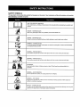
SAFETY SYMBOLS
Thispagedepictsanddescribes
safetysymbols
thatmayappearonthisproduct.Read,understand,
andfollowall instructions
onthemachine
before
attempting
toassemble
andoperate.
READ THE OPERATOR'S MANUAL(S)
Read, understand,
operate
and follow all instructions
in the manual(s) before attempting
to assemble and
Never
carry ROTATING
passengers.BLADES
Never carry children, even with the blades off.
DANGER
4
DANGER-- ROTATING BLADES
Always look down and behind before and while backing to avoid a back-over accident.
WARNING
ROTATING BLADES
Do not put hands or feet near rotating parts or under the cutting
can amputate hands and feet.
WARNING--THROWN
deck. Contact with the blade(s)
OBJECTS
This machine may pick up and throw and objects which can cause serious personal injury.
WARNING--THROWN
OBJECTS
This machine may pick up and throw and objects which can cause serious personal injury.
BYSTANDERS
Keep bystanders, helpers, children and pets at least 75 feet from the machine while it is in
operation.
WARNING--
SLOPEOPERATION
Do not operate this machine on a slope greater than 15 degrees.
A
WARNING-- HOT SURFACE
Engine parts, especially the muffler, become extremely hot during operation. Allow engine and
muffler to cool before touching.
DANGER -- ROTATING BLADES
To reduce the risk of injury, keep hands and feet away. Do not operate unless discharge cover or grass
catcher is in its proper place. If damaged, replace immediately.
Sight and hold this level with a vertical tree...
or a corner of a building...
I
I
I
I
or a fence post
I
I
I
I
I
I
I
I
GO
mower could overturn and cause serious injury. Operate riding mowers up and down slopes, never across the face of slopes.
ROTATING BLADES CAUSE
[
SERIOUS INJURY OR DEATH
i
, DOHOTMOWWHENCHILDREN
OROTHERS
ARE I
* Nm/ER
CARRYClgLDREN
EVEN
WlTII61.ADE(S)
OFF.I
, LOOKgOWNANDBEHINDBEFORE
ANDWHILE |
_OONn
BACKING.
II
•.o,,,NO.IS
NO .Em.NO
I
B
WARNING
This symbol pointsout importantsafety instructions
which,if not followed,could endangerthe personal
safetyand/or propertyof yourselfand others.Readand
followall instructionsin this manualbeforeattempting
to operatethis machine.Failureto complywith these
instructionsmay resultin personalinjury.Whenyousee
thissymbolHEED ITS WARNING!
Your Responsibility
Restrictthe useof thispowermachineto personswho
read,understand,and followthe warningsand instructionsin this manualand onthe machine.
9
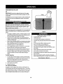
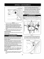
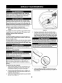
IMPORTANT:
Yourtractorisshippedwithmotoroil in theengine.
However,youMUSTchecktheoil levelbeforeoperating.Refertothe
Service& Maintenance
sectionfor instructions
on checkingtheoil
level.
Attaching
Shipping Brace Removal
IMakesuretheridingmower'sengineisoff, removetheignition
key,
landset theparkingbrakebeforeremovingthe shippingbrace.Refer
Itothe Operationsectionfor instructions
on howto set theparking
ibrake.
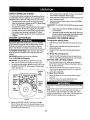
the Battery Cables
CALIFORNIA
PROPOSITION
65
•
Batteryposts,terminals,and relatedaccessories
containleadand
leadcompounds,chemicalsknownto theStateof Californiato
causecancerandreproductive
harm.Washhandsafterhandling.
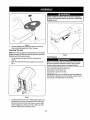
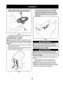
Locatetheshippingbrace,if present,andaccompanying
warning
tagfoundon therightsideofthe mower,betweenthedischarge
chutedeflectorandthecuttingdeck.SeeFig.2.
batterycables,alwaysconnectthePOSITIVECRed)
to its terminalfirst,followedbytheNEGATIVE
(Black)wire,
Forshippingreasons,bothbatterycableson yourequipmenthave
beenleft disconnectedfromtheterminalsat thefactory.Toconnect
thebatterycables,proceedas follows:
NOTE:Thepositivebatteryterminal
is markedPos.(+).Thenegative
batteryterminalis markedNeg.(-).
1. Removethe plasticcover,if present,fromthepositivebattery
terminalandattachtheredcabletothe positivebatteryterminal
(+)with theboltand hexnut.SeeFigure1.
2. Removetheplasticcover,if present,fromthenegativebattery
terminalandattachtheblackcabletothe negativebattery
terminal(-) withtheboltand hexnut.SeeFigure1.
Figure 2
Placethedecklift leverinthehighestcuttingposition.Referto
SettingtheCuttingHeightintheOperationsectionofthis manual.
Whilepushing
thedischarge
chutedeflector
towards
themachine
with
yourlefthand,remove
theshipping
bracewithyourrighthandbygraspingit between
yourthumbandindexfingerandrotating
itclockwise.
Theshippingbrace,usedforpackagingpurposesonly,mustbe
removedanddiscardedbeforeoperatingyourridingmower.
Themowingdeckiscapableofthrowingobjects.Failureto operate
theridingmowerwithout
thedischargecoverin theproperoperating
positioncouldresultin seriouspersonalinjuryand/orproperty
damage.
..
Attaching
J
Wheel
If thesteeringwheelforyourtractordid notcomeattached,the
hardwareforattachingit hasbeenpackedwithinthesteeringwheel,
beneaththesteeringwheelcap.Carefullypryoff thesteeringwheel
capandremovethehardware.
t. Withthewheelsofthetractorpointingstraightforward,placethe
steeringwheeloverthesteeringshaft.
2. Placethewasher(withthecuppedsidedown)overthesteering
wheelandsecurewiththe hexbolt.See Fig.3.
Figuret
3.
The Steering
Positiontheredrubberbootoverthepositivebatteryterminal
to
help protectit fromcorrosion.
NOTE: If the battery is put into service after the date shown on top of
battery, charge the battery as instructed in the Service & Maintenance
section of this manual prior to operating the tractor.
10
\
3.
.
Figure3
Placethe steeringwheelcapoverthe centerof thesteering
wheeland pushdownwarduntilit "clicks"intoplace.
Attaching The Seat
NOTE:If yourseatwasshippedmountedbackwardsonthe seatpivot
bracket,pulloutthetabfoundonthe seatstopandholdit openwhile
slidingtheseatoff theseatpivotbracket.
1,
Lineup theplasticseatspacerswiththeslotsin seatpivot
bracket,
2.
Slideseatin untilfrontseatspacerengagestheseatstop.See
Fig.4.
Figure5
Tire Pressure
It_ld
be mainta'_d at all times. Neverexceed'the
maximuminflationpressure shownon the sidewallof the tire.
f
The recommendedoperating tire pressure is:
Approximately10 psi forthe rear tires
Approximately
14psiforthefronttires
IMPORTANT"Refertothetiresidewallforexacttire manufacturer's
recommended
ormaximumpsi.Donotoverinflate.
Uneven
tirepressurecouldcausethecutting
decktomowunevenly.
\
J
Figure4
Toadjustthepositionof theseaton modelsequippedwitha seat
adjustmentlever,movetheseatadjustmentlever(locatedunder
theseat)to theleftandslidetheseatforwardor rearwarduntilit
securelyengagesintoa seatstop.SeeFig.5. Makesureseatis
bckedintopositionbeforeoperatingthetractor.
11
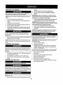
B
A
C
I
D
G
F
\
E
J
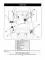
Figure 6
A
Speed Control Lever/Parking Brake Lever
B
Throttle/choke control lever
C
Ignition Switch Module
D
Deck Lift Lever
E
PTO Lever (Blade Engage)
F
G
Cup Holder
Shift Lever
H
Seat Adjustment Lever
I
Clutch-BrakePedal
NOTE" Any referencein this manual to the RIGHTor LEFT side of the tractor is observed from operator's seat position facing forward towards
the front of tractor,
Meets ANSI Safety Standards
Craftsman Tractorsconform to the safety standard of the American National Standards Institute (ANSI).
12
SPEED CONTROLLEVER
SHIFT LEVER
Thespeedcontrollever,locatedon theleftsideof the
tractor'sdashconsole,allowsyoutoregulatetheground
speedofthelawntractor.Touse,depresstheclutchbrakepedalandmovetheleveroutof the parkingbrake
notchand forwardto increasethetractor'sgroundspeed.
Whena desiredspeedhasbeenreached,releasethe
leverintoan appropriatenotchto maintainthatspeed.
Toslowthetractor'sgroundspeed,depresstheclutchbrakepedalandmovethespeedcontrolleverrearward
and releaseit intoa notch.
Theshiftleverislocated
ontheleft
sideofthefenderandhasthree
positions,
FORWARD,
NEUTRAL
andREVERSE.
Thebrakepedal
mustbedepressed
andthetractor
mustnotbeinmotion
whenthe
movingshiftlever.
IMPORTANT;Neverforcethe
shiftlever.Doingsomayresultin
seriousdamagetothetractor's
transmission.
PARKING BRAKE
Tosettheparkingbrake,fullydepresstheclutch-brake
pedal.Movethespeedcontrol
leverall thewaydownand
intotheparkingbrakeposition.Releasetheclutch-brake
pedalto allowtheparkingbraketo engage.
Toreleasethe parkingbrake,depresstheclutch-brakepedaland
movethespeedcontrolleveroutofthenotchesto thedesiredposition.
Releasethespeedcontrolleverandtheclutch-brakepedal.
DECK
NOTE:Theparkingbrakemustbe setif theoperatorleavestheseat
with theenginerunningor theenginewillautomatically
shutoff.
Foundonthetractor'srightfender,thePTO(bladeengage)
leveris usedto engagepowerto thecuttingdeckor other
(separately
available)attachments.
Tooperate,movethe
leverall thewayforward.Movingtheleverall theway
rearwardintothePTOOFFpositiondisengagespowertothe
cuttingdeck/attachment.
THROTTLE/CHOKE
CONTROL
LEVER
LIFT LEVER
Foundonyourtractor'srightfender,the decklift leveris used
tochangetheheightof thecuttingdeck.ToUse,movethe
levertotheleft,thenplaceinthenotchbestsuitedfor your
application.
PTO (BLADE
ENGAGE)
LEVER
Thethrottle/chokecontrolleveris locatedon therightsideofthetractor'sdashpanel.Thislevercontrolsthespeedoftheengineandwhen
pushedall thewayforward,thechokecontrolalso.Whenset in a given NOTE:ThePTO(bladeengage)levermustbe inthe
position,thethrottlewillmaintaina uniformenginespeed.
disengaged(PTOOFF)positionwhenstartingtheengine.
IMPORTANT=Whenoperatingthetractorwiththecuttingdeck
CUP HOLDER
engaged,thethrottle/chokecontrollevermustalwaysbe in the FAST
Thetractor's
cupholderis locatedon thefendertotheleftof
(rabbit)position.
theseat.
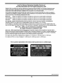
IGNITION
SWITCH MODULE
SEAT ADJUSTMENT
LEVER
The key switch module is usedto
start and stop the engine.It is also
used to activate the ReverseCaution
Mode (bladesoperate while riding
in reverse). Insert key into the key
switchmodule and turn clockwise to
the START position. Releasethe key
into the normal mowing position once
engine has started. The headlights
will be activated in the Normal (and
Reverse Caution) modes.
The seat adjustment leveris on the front side of the seat. Usethis
leverto adjust the seat forward or rearward to a comfortable operating
position, See the "Service & Maintenance"section later in this manual
for instructions.
CLUTCH-BRAKE
PEDAL
The clutch-brakepedal is located on the left side of the lawntractor,
along the running board. Depress the clutch-brake pedal part way
down when slowing the tractor by changing speeds (Referto Speed
Control Lever). Depress the pedal all the way down to engage the disc
brake and bring the tractor to a complete stop.
To stop the engine,turn the ignition key
counterclockwise to the STOPposition,
NOTE; The pedal must be depressedto start the engine. Referto
Safety InterlockSwitches later in this section of this manual,
IMPORTANT:
Priortooperatingthetractor,referto both"Safety
InterlockSystem"and"StartingTheEngine"in theOperationsection
ofthis manualfordetailedinstructionsregardingthe IgnitionSwitch
Moduleand operatingthetractorin REVERSE
CAUTIONMODE.
I moveshiftleverintoneutralposition,setparkingbrake,stopengine
andremovekeyto preventunintendedstarting.
13
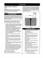
GAS AND OIL FILL-UP
'x
Oil
IMPORTANT: Yourtractor is shipped withmotor oil in the engine.
However,youMUST checkthe oillevelbefore operating.Be careful
nottooverfill.
For instructions
on howto checkthe engineoil, referto CheckingThe
EngineOil in the Service and Maintenancesectionofthismanual.
Gasoline
Thegasoline tankis located underthe hood. Do notoverfill.
Jfl_.
everfuel machineindoors
J__sh
pipes,and other sources of ignition,
cigarettes, cigars,
NOTE : Purchase gasoline in small quantities.Do not use gasoline left
over from the previousseason, to minimize gum deposits in the fuel
system.
•
Figure 7
This engine is certified to operate on unleaded gasoline. For best
results,fill the fuel tank with only clean,fresh, unleaded gasoline
witha pump sticker octane rating of 87 or higher.
Gasohol(up to 10% ethyl alcohol, 90% unleaded gasoline by
volume) is an approved fuel. Other gasoline/alcohol blends, such
as E85, are not approved.
•
•
•
•
MethylTertiary Butyl Ether (MTBE) and unleaded gasoline blends
(up to a maximum of 15% MTBEby volume) are approvedfuels.
Other gasoline/ether blendsare not approved.
Fillfuel tank outdoors or in well-ventilatedarea.
•
Donot overfill fuel tank. Filltank to no morethan 1/2 inch below
•
•
bottom of filler neck to allow space for fuel expansion.
•
Neverremovegas cap or add fuel while the engine is hot or running. Allow engine to cool at least two minutes before refueling.
•
If gasoline is spilled, wipe it off the engine and equipment. Move
machineto another area. Wait 5 minutes before starting the
engine.
To Add Gasoline
1.
2.
Turnthe engine off and let engine cool at least 2 minutes before
removingthe fuel cap. The gasoline tank is under the rearfender.
with the fuel fill cap located in the centerof the rear fender.
The fuel cap is tethered to the tractor to prevent its loss. Do not
attempt to removethe cap from the tractor.
Fill the fuel tank with gasoline.
3.
Reinstallthe fuel cap.
For California
•
•
•
•
•
•
•
Avoid Serious Injury or Death
Goup anddownslopes,notacross.
Avoidsuddenturns.
Donotoperatetheunitwhereitcouldsliportip.
Ifmachinestopsgoinguphill,stopbladesandbackdownhill
slowly.
Donotmowwhenchildrenorothersarearound.
Nevercarrychildren,
evenwithbladesoff.
Lookdownandbehindbeforeandwhilebacking.
Keepsafetydevices(guards,
shields,andswitches)inplace
and working.
Removeobjectsthatcouldbe thrownbytheblades.
Knowlocationandfunctionofall controls.
•
Besurebladesandenginearestoppedbeforeplacinghandsor
feet nearblades.
•
Beforeleavingoperator'sposition,stoptractor,disengage
blades,engageparkingbrake,shutengineoff,andremovekey.
Read Operator's Manual
Models:
For Californiamodels equipped witha tethered, ratcheting fuel cap,
STOP filling tank once fuel is seen inside the filler neck. This ensures
that a proper expansionvolume is created, otherwise the fuel can overflow creatinga hazardoussituation. Do NOT till to the top of the filler
neck. On California models, fill the tank inaccordance with Figure7.
14
SAFETY INTERLOCK
SYSTEM
4.
Thesafetyinterlocksystemisdesignedfor safeoperation
of thetractor.If thissystemshouldevermalfunction,
do notoperatethetractor,
immediately
contact1-800-4-MY-HOME
tohavethesystemserviced.
•
Thesafetyinterlocksystempreventstheenginefromstarting
unlesstheparkingbrakeis engagedand thePTOCBlade
Engage)
leveris in thedisengaged
(OFF)position.
•
Thesafetyinterlocksystemwillautomatically
shutoff theengineif
theoperatorleavestheseatbeforeengagingtheparkingbrake.
•
Thesafetyinterlocksystemwillautomatically
shutoff theengine
if theoperatorleavesthetractor'sseatwiththe PTO(Blade
Engage)leverengaged,regardlessofwhethertheparkingbrake
isengaged.
REVERSE
CAUTION
MODE
5.
Onceactivated(indicatorlightON),thetractorcanbe drivenin
reversewiththe cuttingblades(PTO)engaged.
Alwayslookdownand behindbeforeandwhilebackingto make
surenochildrenarearound.
6.
Afterresumingforwardmotion,returnthekeyto theNORMAL
MOWINGposition.
IMPORTANT:TheREVERSECAUTIONrvIODE
willremainactivated
until:
a.
Thekeyis placedin eithertheNORMALMOWINGposition
or STOPposition.
b.
Theoperatorengagestheparkingbrakebyfullydepressing
theclutch-brake
pedalandholdingit downwhilemovingthe
speedcontrolleverintothePARKBRAKEposition.
ENGAGING
THE PARKING BRAKE
To engage the parking brake:
Useextremecautionwhileoperating
thetractorin theREVERSE
CAUTIONMODE.Alwayslookdownand behindbeforeandwhile
backing.Donotoperatethetractorwhenchildrenorothersare
around.Stopthetractorimmediatelyif someoneentersthearea.
Fullydepressthe clutch-brake
pedalandholdit downwithyour
foot,
2.
Movethespeedcontrolleverall thewaydownandintothe
parkingbrakeposition.
Releasethe clutch-brake
pedalto allowtheparkingbraketo
engage.
3.
The REVERSECAUTIONMODEpositionofthekeyswitchmodule
allowsthetractor
tobeoperated
inreverse
withtheblades(PTO)
engaged.
To release the parking
Depresstheclutch-brakepedaland movethespeedcontrol
leveroutof theparkingbrakeposition
andintoa desiredspeed.
SETTING THE CUTTING
HEIGHT
IMPORTANT-TheoperatorMUSTbeseatedin thetractor
seat
Startengineas instructedintheStartingTheEnginesection,
TurnthekeyfromtheNORMALMOWING(Green)position
tothe
REVERSECAUTIONMODE(Yellow)
position
ofthekeyswitch
module.SeeFigure8.
1
Select the height position of the cutting deck by placing the
deck lift lever in any of the six different cutting height notches on
the right sideof the fender.
2.
Adjust the deck wheels so that they are between ¼-inch and
V2-inchabove the ground when the tractor is on a smooth,fiat
surface such as a driveway.
Reverse
To adjust
f
_
Push
IndicatorffNO c.,.o._. A.OU.D.-_-----_,..._ Button
1.
2.
,.._--_-.,-_.___________________J
H=
3.
Reverse__.
brake:
1.
IMPORTANT"Mowingin reverseis notrecommended.
TousetheREVERSECAUTIONMODE:
1,
2.
1.
Deck
Wheels:
Removetheflangelocknuton theshoulderboltsecuringthe
deckwheel.
Positionthewheelto thedesiredheightaslistedabove.
Securetheshoulderboltwiththeflangelocknut.
I limg imimn
PosiiO.sto
position_1
Keephandsandfeetawayfromthedischargeopeningof thecutting
deck.
Mode
\_ _ )/J
\_/
] _
NOTE: The deck wheels are an anti-scalp feature of the deck and
are not designed to support the weight of the cutting deck. Referto
Leveling inthe Maintenance& Service section of this manualfor more
detailed instructions regarding various deck adjustments.
}'Start
position
J
Figure 8
3.
DepresstheREVERSE
PUSHBUTTON(Orange,
Triangular
Button)at thetop,rightcomerof thekeyswitchmodule.Thered
indicatorlightat thetop,left comerofthekey switchmodulewill
be ONwhileactivated.SeeFigure8.
15
STARTING
THE
ENGINE
2.
3.
Donotoperatethetractorif theinterlocksystemis malfunctioning.
Thissystemwasdesignedfor yoursafetyandprotection.
IMPORTANT:DoNOTusethe shiftlevertochangethedirection
oftravelwhenthetractorisin motion.Alwaysusethebrakepedalto
bringthetractortoa completestop beforeshifting.
4. Releasetheparkingbrakebydepressingtheclutch-brakepedal
and positioningthespeedcontrolleverindesiredposition.
NOTE:Referto theGasolineandOilfill-upinstructionsearlierin this
section.
1. Insertthetractorkeyintotheignitionswitch.
2. PlacethePTO(BladeEngage)leverin thedisengaged
(OFF)
position.
3. Engagethetractor'sparkingbrake.
4, Activatethechokecontrolbymovingthethrottle/chokeleverall
the wayup intothechokeposition.
5. TurntheignitionkeyclockwisetotheSTARTposition.Afterthe
enginestarts,releasethekey.It willreturnto theON(or Normal
Mowing)position.
I
6.
pedalup.
Movethe throttle
leverintotheFAST(rabbit)position.
Placetheshiftleverin eithertheFORWARDor REVERSE
position.
IMPORTANT:First-timeoperatorsshouldusespeedpositions1 or
2. Becomecompletelyfamiliarwiththetractor'soperationandcontrols
beforeoperatingthetractorin higherspeedpositions.
5.
6.
Releaseclutch-brakepedalslowlyto putunitintomotion.
Thelawntractorisbro_Jght
to a stopbydepressingtheclutchbrakepedal.
NOTE:Whenoperatingtheunitinitially,therewillbe littledifference
betweenthehighesttwo speedsuntilafterthebeltshaveseated
themselves
intothepulleysduringthebreak-inperiod.
yourngine's
Aftertheenginestarts,deactivatethechokecontrolandplacethe
throttlecontrolin theFASTposition.
Beforeleavingtheoperator'spositionforanyreason,disengagethe
blades,placetheshiftleverin neutral,engagetheparkingbrake,
shutengineoff andremovethekey.
NOTE:DoNOTleavethechokecontrolon whileoperatingthetractor. IMPORTANT:Whenstoppingthetractorforanyreasonwhileon a
Doingsowill resultin a "rich"fuelmixtureandcausetheengineto run grasssurface,always:
poorly.
1. Placetheshiftleverin neutral,
STOPPING
THE ENGINE
2. Engagetheparkingbrake,
3.
I _ouncl'against'
l__ore
operating
Shutengineoff andremovethekey.Doingsowillminimize
the
possibilityof havingyourlawn"browned"byhotexhaustfrom
yourtractor'srunningengine.
If unitstallswithspeedcontrolin highspeed,or if unitwillnotoperate
withspeedcontrolleverin a lowspeedposition,proceedasfollows:
1. Placeshiftleverin NEUTRAL.
theengi'ne.:rhoroughlyinspectthe
restariingand
1. If the bladesareengaged,placethe PTO(BladeEngage)leverin
thedisengaged(OFF)position.
2. rum the ignitionkeycounterclockwise
totheSTOPposition.
3. Removethekeyfromtheignitionswitchto preventunintended
starting.
DRIVING THE TRACTOR
Avoidsuddenstarts,excessivespeedandsuddenstops.
-
- !'lW-1 ;t_ll_[e,--
Donotleavethe seatof thetractorwithoutfirstplacingthePTO
I
(BladeEngage)leverin thedisengaged(OFF)position,depressing I
thebrakepedalandengagingtheparkingbrake.If leavingthetractorJ
unattended,
alsoturntheignitionkeyoffand removethekey.
I
_.---'.
t, _, k, _ --
---
-!
I Alwayslookdownandbehindbeforeand whilebackingup to avoida
I back-over
accident.
1.
Depressthebrakepedalto releasetheparkingbrakeandlet the
16
2.
3.
4.
5.
6.
7.
Restartengine.
Placespeedcontrolleverin highestspeedposition.
Releaseclutch-brake
pedalfully.
Depressclutch-brakepedal.
Placespeedcontrolleverin desiredposition.
Placeshiftleverin eitherFORWARDor REVERSE,
and follow
normaloperatingprocedures.
DRIVING ON SLOPES
MOWING
RefertotheSLOPEGAUGEintheImportantSafeOperationPractices
sectionofthemanualto helpdetermineslopeswhereyoumayoperate
thetractorsafely.
Tohelpavoidbladecontactor a thrown
objectinjury,keepbystanders, helpers,childrenand petsat least75feetfromthemachine
whileit is in operation.Stopmachineif anyoneentersthearea.
Thefollowinginformation
willbehelpfulwhenusingthecuttingdeck
withyourtractor:
•
•
•
Mowup anddownslopes,NEVERacross.
Exerciseextremecautionwhenchangingdirectionon slopes.
Watchforholes,ruts,bumps,rocks,or otherhiddenobjects.
Uneventerraincouldoverturnthemachine.Tallgrasscanhide
obstacles.
•
Avoidturnswhendrivingon a slope.If a turnmustbe made,turn
downtheslope.Turningupa slopegreatlyincreasesthechance
ofa rollover.
Planyourmowingpatternto avoiddischarge
of materialstoward
roads,sidewalks,
bystandersandthelike.Also,avoiddischarging
materialagainsta wallor obstructionwhichmaycausedischarged
materialto ricochetbacktowardtheoperator.
•
•
•
Avoidstoppingwhendrivingupa slope.If it is necessaryto stop
whiledrivingupa slope,startup smoothlyandcarefullyto reduce
thepossibilityofflippingthetractoroverbackward.
ENGAGING
THE BLADES
EngagingthePTO(BladeEngage)transferspowertothecuttingdeck
or other(separately
available)attachments.
Toengagetheblades,
proceedasfollows:
1. Movethethrottle/chokecontrolleverto theFAST(rabbit)position.
2. GraspthePTO(BladeEngage)leverandpivotitall theway
forwardintotheengaged(ON)position.
3. Keepthethrottleleverin the FAST(rabbit)positionforthemost
efficientuseofthecuttingdeckor other(separately
available)
attachments.
NOTE:Theenginewillautomatically
shutoff ifthePTO(Blade
Engage)isengagedwiththe shiftleverin positionfor reversetravel
withtheignitionkeyin theNORMALMOWINGposition.
MULCHING
•
•
•
•
•
Donotmowat highgroundspeed,especiallyif a mulchkitor
grasscollectoris installed.
Forbestresultsit is recommended
thatthefirsttwolapsbecut
withthedischargethrowntowardsthecenter.Afterthe firsttwo
laps,reversethedirectionto throwthedischargeto theoutside
forthebalanceofcutting.Thiswillgivea betterappearance
tothe
lawn.
Donotcut thegrasstoo short.Shortgrassinvitesweedgrowth
andyellowsquicklyin dryweather.
Mowingshouldalwaysbe donewiththeengineatfullthrottle.
Underheavierconditionsit maybenecessarytogo backoverthe
cutareaa secondtimeto geta cleancut.
DoNOTattemptto mowheavybrushandweedsandextremely
tallgrass.Yourtractoris designedto mowlawns,NOTclear
brush.
Keepthebladessharpandreplacethebladeswhenworn.Refer
to CuttingBladesin theServicesectionofthis manualforproper
bladesharpening
instructions.
HEADLIGHTS
•
•
A mulch kit is available as a n attachment. Mulching is a process of
recirculating grass clippings repeatedly beneath the cutting deck.
The ultra-fine clippings are then forced back into the lawn where
they act as a natural fertilizer.
A mulchkit canbepurchasedthroughtheretaillocationin whichyou
purchasedthistractor.Formoreinformation,simply contactSears
at 1-800-4-MY-HOME®.
USING THE DECK LIFT LEVER
Toraisethecuttingdeck,movethedecklift levertothe left,thenplace
itin the notchbestsuitedforyourapplication.RefertoSettingThe
CuttingHeightearlierin this Operationsection.
17
ThelampsareONwhenever
thetractor's
engineisrunning.
ThelampsturnOFFwhentheignitionkeyismovedtotheSTOP
position,
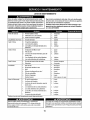
MAINTENANCE
SCHEDULE
Beforeperforming
anytypeofmaintenance/service,
disengage
all
controlsandstoptheengine.Waituntilallmovingpartshavecometo
a complete
stop.Disconnect
sparkplugwireandgrounditagainstthe
enginetopreventunintended
starting.
Alwayswearsafetyglassesduring
operation
or whileperforming
anyadjustments
or repairs.
BeforeEachUse
Followthemaintenance
schedulegivenbelow.Thischartdescribes
serviceguidelinesonly.UsetheServiceLogcolumnto keeptrack
of completed
maintenance
tasks.Tolocatethe nearestParts&
RepairServiceCenteror toscheduleservice,simplycontact
1-800-4-MY-HOME®.
1.
2.
Engineoil level
Mufflerareaandcontrols
4.
5.
Check
Clean
3.
Fingerguard
6.
Clean
Inthe FirstFiveHours
7.
EngineOil
8.
Change
Every10 Hours
9. Hood/Dashair vents
10. Batteryterminals
11. Deckspindlesandidler
bracket
12. Clean
13. Clean
15. Airfilter'sprecleaner*
16. Air filter*
20. Clean
17. Midsteeringarms,pivot
shafts,and axles
22. Lubricate
18. Frontwheelbearings
19. Frontdeckwheels
23. Lubricate
Every50 hours
25. Engineoil/Oil filter
26. Muffler
27. Change/Replace
Annually
29. Air filter
36. Replace
37. Replace
Every25 hours
30. Air filter's pre-cleaner
31. Spark plug
32. Air cooling system*
33. Fuel filter
34. Steering Gears
35. RearWheels
BeforeStorage
43. Hood/Dash air vents
44. Batteryterminals
14. Lubricate
21. Clean
24. Lubricate
28. Check
38. Replace
39. Clean
40. Replace
41. Clean
42. Remove and grease axles
50. Clean
51. Clean
45. Mid steeringarms, pivot
shafts, and axles
52. Lubricate
46. Frontwheel bearings
47. Front deck wheels
53. Lubricate
48. Deck spindles and idler
bracket
49. Pedal pivot points
*Service more frequently under dusty conditions.
54. Lubricate
55. Lubricate
56. Lubricate
=._======,===m-z_VlVl_,1
=t_i i_[€ _
Before performingany maintenanceor repairs, disengage the PTO
(Blade Engage Lever), engage the parkingbrake, stop the engine
and remove the key to prevent unintendedstarting.
Irounding me_ause
Exercise caution to avoid burns.
18
burns to the skin.
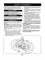
ENGINE MAINTENANCE
Checking
Changing
Engine Oil
the Engine Oil
Theengineoilshould
bechanged
inthefirst5 hoursandthenevery
50
hours
oronce
a
season.
T
ochange
theengineoil,proceed
as
Onlyusehighqualitydetergent
oilratedwithAPIservice
classification
follows:
SF,8G,SH, orSJ.Selecttheoil'sSAEviscosity
gradeaccording
to
1. WithengineOFFbutstillwarm,disconnect
sparkplugwireand
theexpected
operating
temperature.
Follow
thechartbelow.
keepit awayfromsparkplug.
Althougn
multi-viscosity
oils(5W20,10W30,etc.)improve
starting
2. Remove
theoiltillcap/dipstick
fromtheoiltill tube.SeeFigure9.
incoldweather,
theywillresultinincreased
oilconsumption
when
3. Cliptheoil drainsleeve(packed
withthismanual)
ontotheoil
usedabove32°F.Checkyourengineoil levelmorefrequentlytoavoid
drainport.Routetheopposite
endofthesleeveintoanappropripossible
enginedamagefromrunning
lowonoil.
ateoilcollection
container
witha capacitygreatenoughtocollect
theusedoil.
4.
Remove
theoildrainplug,Theoilwill begintodrainoutofthe
engine.
5. Aftertheoilhasfinisheddraining,
replacetheoildrainplugand
tighten.Becarefulnottoovertighten.
6. Removetheoildrainsleeveandstoreforlateruse.
\
Oil Viscosity Chart
7.
J
Tochecktheengineoil,proceedas follows:
•
Ensurethatthetractor
is ona levelsurface,
•
1.
2,
3.
Refilltheenginewithnewmotoroiluntiltheoillevelonthe
dipstick
readsFULL.Replace
theoilfill cap/dipstick.
Usedoil is a hazardous
wasteproduct.Disposeof usedoil properly.
Donotdiscardwithhouseholdwaste.Checkwithyourlocalauthoritiesor or contact1-800-4-MY-HOME
fora list ofsafedisposal/
recyclingfacilities.
Cleanthe oil fillareaofanydebris.
Removethedipstickandwipewitha cleancloth.
Insertandtightendipstick.
Removethedipstickandchecktheoil level.It shouldbe atthe
Fullmarkonthe dipstick.SeeFigure9.
Changing
f
Dipstick----.--_.___.
the Oil Filter
1.
Drain the oil from the engine as described above,
2.
Removethe oil tilter and dispose of properly. See Figure 10.
Oil Filter
%.
"_"--_
Oil Drain
Sleeve
Oil Drain
Valve
L
......
,.
J
Figure 10
J
4.
Figure9
If low,addoil slowlyintotheengineoil fill.Donotoverfill.Nter
addingoil,waitoneminuteandthenrechecktheoil level.
3.
4.
5.
5.
Replaceandtightendipstick.
19
Beforeyouinstallthenewoil filter,lightlylubricatetheoil filter
gasketwithfresh,cleanoil.
Installtheoil tilterbyhanduntilthegasketcontactstheoil filter
adapter,thentightentheoil filter1/2to3/4 turns.
Addoil asdescribedabove.
6.
Startand runtheengine.Astheenginewarmsup,checkforoil
leaks.
7.
Stoptheengineandchecktheoil level.It shouldbe atthe FULL
markon thedipstick.
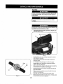
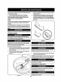
Fuel Filter
Donotusepressurized
air or solventstocleantheair cleaner
cartridge.
irnsor death.
•
Keepgasolineawayfromsparks,openflames,pilotlights,heat,
andotherignitionsources.
J
Figure 12
Check fuel lines, tank, cap, and fittings frequently for cracks or
leaks. Replace if necessary.
f
•,%
/
Clamp
•
Before replacingthe fuel filter,drain the fuel tank as per the
instructions below.
Do not drain fuel when the engine is hot. Allow the engine
adequatetime to cool. Drain fuel into an approvedcontainer
outdoors,away from open flame.
Fuel
Line
Drain any large volumeof fuel from the tank by disconnecting the
fuel line from the in-linefuel filter near the engine.
Removethe fuel line from the In-line side (side towards the fuel
tank) of the fuel filter.
Tab
Replacement parts must be the sameand installedin the same
position as the original parts.
If fuel spills, wait until it evaporatesbeforestarting engine.
j
•
Figure11
2O
Before replacing the fuel filter, drain the fuel tank. Otherwise,fuel
can leak out and cause a fire or explosion.
ToDrainthefuel:
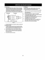
Air Cleaner
1.
Theairfiltersystemusesa cylindrical
cartridge.
Thismodelalso
includes
a pre-cleaner
thatcanbewashedandreused.
f
Locatethefuelfilter,whichisrouted
on theleftsideoftheengine
between
thefueltankandthecarburetor,
andmaybeattachedto
theenginewitha tiestrap.Cutthetiestrap,ifpresent,
thenpinch
thein-line
clamponthefuelfilterwitha pairofpliers,
slidethe
clampupthefuelline.Pullthefuellinefreefromthefilterandplace
Electrode
Porcelain
I
.....
.030(.76 mm) gap
)
Figure13
theopenendofthelineintoan approved
containertodrainthefuel,
Tochangethe fuel filter:
1. Usepliersto squeezethetabson theotherclamp (theout-line
sideofthefuelfilter),thenslidetheclampawayfromthefuelfilter.
Twistand pullthefuellineoff ofthefuelfilter.See Figure11.
2. Checkthefuellinesforcracksor leaks.Replaceif necessary.
3. Replacethefuelfilterwithanoriginalequipmentreplacement
filter.Call 1-800-4-MY-HOME®
to purchasetheoriginalequipmentreplacement
filter.
4.
Securethefuellineswiththeclamps.
21
1. Remove
thefasteners(A)andtheairfiltercover(B).SeeFigure
12.
2.
Toremove
thefilter(C),lifttheendofthefilterandthenpullthe
filteroff theintake(D).
3. Remove
thepre-cleaner
(E),ifequipped,
fromthefilter.
4. Toloosendebris,
gentlytapthefilterona hardsurface.
Ifthefilter
isexcessively
dirty,replace
witha newfilter.
5. Washthepre-cleaner
inliquiddetergent
andwater.Thenallowit
tothoroughly
airdry.Donotoilthepre-cleaner.
6. Assemblethedry pre-cleaner
tothefilter.
7. Installthefilteron theintake.Pushtheendofthe filterintothe
baseasshown.Makesurefilterfitssecurelyin thebase.
8, Installairfilter coverand securewithfasteners.
Spark Plug
1.
2.
3.
LUBRICATION
Cleanareaaroundthesparkplugbase.Donotsandblastspark
plug.Sparkplugshouldbecleanedbyscrapingor wirebrushing
andwashingwitha commercial
solvent
Removeandinspectthesparkplug.Checkgapto makesureit is
setat .030".SeeFigure13.
Replacethesparkplug(Champion®
RC12YC)
oncea season.
Beforelubricating,repairing,or inspecting,alwaysdisengagePTO
(BladeEngageLever),moveshiftleverintoneutralposition,set
parkingbrake,stopengineandremovekeyto preventunintended
starting.
Pivot Points & Linkage
Muffler
Temperature
of mufflerandnearbyengineareasmayexceed150° F
(65"C).Avoidcontactwiththeseareas.
Inspect
muffler
periodically,
andreplaceif necessa_ry.
Replacementparts for the mufflermust be the same and installedin the
/
/
/
/
/
/
/
!
J
\
Figure t5
Lubricate all the pivot pointson the drive system, parkingbrake and lift
linkage at least once a seasonwith light oil.
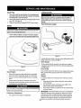
Rear Wheels
The rearwheels should be removedfrom the axles once a season.
Figure 14
same position as the original parts.
Clean
•
•
Engine
Daily or before every use, clean grass, chaff or accumulated
debris from engine. Keep linkage, spring, and controls clean.
Keep area around and behind mufflerfree of any combustible
debris.
•
Keepingengine clean allows air movementaround engine.
.
Engine parts should be kept clean to reducethe risk of overheating and ignition of accumulateddebris.
Donotusewaterto cleanengineparts.Watercouldcontaminatefuel
system.Usea brushor drycloth.
Carburetor
•
Adjustment
Thecarburetoron thisengineis notadjustable.
Lubricate the axles and the rims well with an ali-purposegrease before
re-installing them.
Front Axles
Eachend of the tractor's front pivot bar may be equipped with a grease
fitting. Lubricate with a grease gun after every 25 hours of tractor
operation.
Battery
The battery is sealed and is maintenance-free.Acid levelscannot be
checked.
•
Always keepthe battery cables and terminals clean and free of
corrosive build-up.
•
After cleaning the battery and terminals,apply a light coat of
petroleumjelly or grease to bothterminals.
•
Alwayskeep the rubber boot positioned over the positive terminal
to prevent shorting.
IMPORTANT: If removingthe battery for any reason, disconnectthe
NEGATIVE(Black) wire from its terminal first, followed by the POSITIVE (Red) wire. When re-installingthe battery,always connect the
POSITIVE(Red) wire to its terminalfirst, followed by the NEGATIVE
(Black) wire. Be certain that the wires are connected to the correct
22terminals; reversingthem could change the polarity and result in
f
Hex Cap Screw
J
Figure 16
damage to your engine'salternating system.
Cleaning
Figure 17
CLEANING
Battery
AND DECK
Anyfuelor oil spilledon themachineshouldbe wipedoff promptly.Do
NOTallowdebristo accumulatearoundthecoolingfins oftheengine
or onanyotherpartofthemachine.
Clean the batteryby removing it from the tractor and washing with
a baking soda andwater solution. If necessary,scrape the battery
terminals witha wire brush to remove deposits. Coat terminalsand
exposedwiring withgrease or petroleumjelly to prevent corrosion.
Battery
THE ENGINE
f
Failures
Bow-TieClip
Some common causesfor battery failure are:
•
Incorrectinitial activation
•
Overcharging
•
•
•
Freezing
Undercharging
Corrodedconnections
These failures are NOT covered by your tractor's warranty.
Figure18
IMPORTANT= The use of a pressurewasher to clean your tractor is
NOT recommended.It may causedamage to electrical components,
spindles, pulleys, bearings or the engine.
A screw plug can be found on your tractor's deck surface as seen in
Fig. 14. This plug can be replacedwith a waterport to be used as part
of a separately-availabledeck wash system.
The DeckWash SystemTM is used to rinsegrass clippings from the
deck's underside and preventthe buildup of corrosivechemicals.
NOTE=A deck wash systemcan be purchasedthrough the retail
location inwhich you purchasedthis tractor. For moreinformation,
23
simplycall1-800-4-MY-HOME®.
NOTE"Checkthetractor'stirepressurebeforeperforming
anydeck
leveling
adjustments.
RefertoTiresintheServiceseclion
ofthis
manualfor moreinformation
regarding
tirepressure.
Front To Rear
ADJUSTMENTS
f
Thefrontofthecuttingdeckis supportedbya stabilizerbarthatcan
beadjustedto levelthedeckfromfrontto rear.Thefrontof thedeck
shouldbe between¼-inchand3/8-inch
lowerthantherearof thedeck.
Adjustif necessaryasfollows:
1. Withthetractorparkedona firm,levelsurface,placetheleverfor
liftingtheplatformon thesecondto thetopnotch(secondhighest
position)androtatethebladeasclosetothedischargechannel
thatis parallelto thetractor.
2. Measurethedistancefromthefrontofthebladetip totheground
andtherearofthebladetip totheground.Thefirstmeasurementtakenshouldbe between¼"and3/8"
lessthanthesecond
measurement.
Determine
theapproximate
distancenecessaryfor
properadjustmentand proceed,if necessary,
to thenextstep,
3. Locatetheflangelocknuton thefrontsideofthe stabilizer
bracket.SeeFig. 15.
Tightentheflangelocknutto raisethefrontof thedeck;
Loosentheflangelocknutto lowerthefrontofthedeck.
Side to Side
i o
J
Figure 19
If thecuttingdeckappearstobe mowingunevenly,a sideto side
adjustmentcanbe performed.Adjustif necessaryasfollows:
1. Withthetractorparkedona firm,levelsurface,placethedecklift
leverin thesecondfromthetopnotch(secondhighestposition)
androtatebothbladesso thattheyare perpendicular
withthe
tractor.
f
2.
/
Measurethedistancefromtheoutsideof theleftbladetipto the
groundandthedistancefromtheoutsideof therightbladetipto
theground•Bothmeasurements
takenshouldbeequal.If they're
not,proceedtothenextstep.
3. Loosen,butdo NOTremove,thehexcap screwontheleft deck
hangerbracket.See Fig.16.
4. Balancethedeckby usinga wrenchtoturntheadjustmentgear
(foundimmediately
behindthehexcapscrewjust loosened)
clockwise/upor counterclockwise/down.
Thedeckis properly
balancedwhenbothbladetip measurements
takenearlierare
equal.
5. Retighten
thehexcap screwontheleft deckhangerbracketwhen
properadjustmentis achieved.
/
/
I
/
/
/
/
/
/
PTOCable
J
Figure20
Neverattempt to makeany adjustmentswhile the engine is running,
except where specified in the operator's manual,
Leveling the Deck
24
ifyourtractor
hasnotbeenputintouseforanextended
period
oftime, b Remove
thehexflange
nutthatsecures
thebradetothespindle
chargethebattery
asfollows:
assembly.
SeeFig.21.
4. Toproperly
1. Setyourbattery
charger
todeliver
a maxof10amperes.
sharpen
thecuffing
blades,
remove
equalamounts
ofmetalfrombothendsoftheblades
alongthecutting
edges,
Ifyourbattery
charger
isautomatic,
charge
thebattery
untilthe
parallel
tothetrailing
edge,ata 25°- to30° angle.Always
grind
charger
Indicates
thatcharglng
Iscomplete.
Ifthecharger
isnot
eachcutting
bladeedgeequally
tomaintain
proper
bladebalance.
automatic,
charge
fornofewerthaneighthours.
SeeFig.22.
FUSE
One20AMPfuseisinstalledinyourIractor'swiringharnesstoprotect
thetractor's
electrical
system
fromdamage
caused
byexcess'we
amperage.
Iftheelectrical
systemdoesnotfunction,oryourtractor's
engTne
will
notcrank,firstchecktobecertain
thatthefusehasnotblown.
Itcan
befoundattherearoftheunit,underneath
thefenderlocated
bythe
battery.
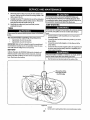
CUTTING
BLADES
%,.
J
Figure 22
Periodically
inspect
thebladeand/orspindle
forcracks
ordamage,
especially
afteryou've
struck
a foreignobject.
Donotoperate
the
machine
untildamaged
components
arereplaced.
Toremove
theblades,proceed
asfollows.
1. Remove
thedeckfrombeneath
thetractor,
(referto Curling
Deck
Removal
earlierin thissection)thengentlyflipthedeckoverto
exposeItsunderside.
2. Placea brock
ofwoodbetween
thecenter
deckhousingbaffle
andthecutting
bladetoactasa stabilizer.
SeeFig.21.
lany me_s
presen_he
blades
withnewones.
5. Testtheblade'sbalanceusinga bladebalancer.
Grindmetalfrom
theheavysideuntilit balances
evenly.
NOTE:Whenreplacing
theblade,besuretoinstallthebladewiththe
sideof theblademarked"Bottom"(orwitha partnumberstamped
in
it)facingthegroundwhenthemower
isintheoperating
position.
I liiv£ ,jejnl[e]O
--
JUsea torquewrench
totighten
thebladespindlehexflangenutto
!between70Ibs-ftand90tbs-ft.
CHANGING
1
J
THE DECK BELT
I_vATI_'I;!011_[_
Besuretoshuttheengineoff,removeignition
key,disconnect
the ]
sparkplugwire(s)
andground
againsttheengine
toprevent
unintended
startingbeforeremoving
thebelt.
!
mnmnimmn [, : ujj [o]o
Figure 21
IAIIbellsonyourtractoraresubjecito,,,,'ear
andshouldbe replaced
if
Ianysignsofweararepresent.
25
8, Remove
thebow-tie
cotter
pinsecuring
thedeck
stabilizer
redto
thedeck.
Slide
thedeck
liftrodfrom
themounting
bracket
onthe
If removingthebattery,disconnectthe NEGATIVE
(Black)wire
deck
asseen
inFig.19.
fromits
terminal
f
irst,followed
by
thePOSITIVE
(Red)wire.When
9. Carefully
remove
thePTO
cable
from
therear
ofthecutting
deck
byremoving
thebow-tie
cotter
pinwhich
secures
it.Remove
the re-installingthebattery,alwaysconnectthe POSITIVE(Red)wireto
itsterminalfirst,followedbytheNEGATVE(Back)wire,
spring
from
thedeck
idler
bracket.
SeeFig,20.
10.Gently
slide
thecutting
deck
(from
theleftside)
outfrom
JUMP STARTING
underneath
thetractor.
TIRES
Neverexceedthemaximuminflationpressureshownon thesidewall
of tire.
Connectpositive(+)cableto positivepost(+)ofyourtractor's
dischargedbattery.
2. Connecttheotherendofthecabletothe(positive+) postofthe
•
Approximately
10 psiforthereartires
jumperbattery.
•
Approximately
14psiforthefronttires
3. Connectthesecondcable(negative-) to theotherpostof the
IMPORTANT:Refertothetiresidewallfor exacttiremanufacturer's
jumperbattery.
recommended
ormaximumpsi.Donotoverinflate.
Uneventirepres4. Connecttheotherendofthe negativecableto theengineblockof
surecouldcausethecutting
decktomowunevenly.
thetractor,awayfromthe battery.Attachto anunpaintedpartto
BATTERY
assurea goodconnection.
The recommended
1.
operating tire pressure is:
California Proposition65 WARNING! Battery posts,terminals, and
relatedaccessoriescontain lead and lead compounds, chemicals
known to the State of California to cause cancer and reproductive
harm. Wash hands after handling.
If thejumperbatteryis installedona vehicle(i.e.car,truck),do NOT
startthevehicle'senginewhenjumpstartingyourtractor.
5
Startthetractor(asinstructedearlierin thissectionof this
f
portion of the
belt routes around
the PTO Pulley
Hex Washer Screws
_Spindle
_.k
• tl_
Pulley
Deck Idler Pulley
o_
_v _
_<)JlII t/°
I
Figure 23
6.
26
manual).
Setthetractor's
parkingbrakebeforeremovingthejumpercables,
Never
store
lawntractorwithfuelin tankindoorsor inpoorly
ventilatedareaswherefuelfumesmayreachanopenflame,spark,
or pilotlightas on a furnace,waterheater,clothesdryer,or gas
appliance.
PREPARING THE ENGINE
DRAINING THE FUEL
1.
IMPORTANT:
Fuelleftin thefueltankduring
warmweatherdetenoratesand willcauseseriousstartingproblems.
2.
Topreventgumdepositsfromforminginsidetheengine'scarburetor
and causingpossiblemalfunctionoftheengine,thefuelsystemmust
be eithercompletelyemptied,or thegasolinemustbetreatedwitha
stabilizerto preventdeterioration.
1. If usinga fuelstabilizer:
a. Readtheproductmanufacturer's
instructionsand recommendations.
b.
2.
Addto clean,freshgasolinethecorrectamountof stabilizer
for thecapacityof thefuelsystem.
c. Fillthefueltankwithtreatedfueland runtheenginefor2-3
minutesto getstabilizedfuelintothecarburetor.
If emptyingthefuelsystem:
a. Donotdrainfuelwhentheengineis hot.Allowtheengine
adequatetimeto cool.Drainfuelintoan approvedcontainer
outdoors,awayfromopenflame.
b. Drainanylargevolumeof fuelfromthetankbydisconnectingthefuellinefromthe in-linefuelfilterneartheengine.
Seethecompleteinstructions
for DrainingTheFuellaterin
this section.
r Gasoline is extremely flammable and can be explosive under certain
conditions. Drain gasoline before storing the equipment for extended
periods. Drain fuel only into an approvedcontainer outdoors, away
from an open flame. Allow engine to cool. Extinguish cigarettes,
cigars, pipes, and other sources of ignition prior to draining fuel.
Store gasoline in an approvedcontainer in safe location.
c.
Reconnectthe fuel line and run the engine until it starts to
falter, thenuse the choke to keep the engine running until all
fuel in the carburetor has been exhausted.
d.
Disconnectthe fuel line and drain any rematninggasoline
from the system
Gasoline is a toxic substance. Dispose of gasoline properly.Contact
your local authorities for approveddisposal methods.
3,
Removethesparkplugandpourone(1)ounceof engineoil
throughthesparkplugholeintothecylinder.Cranktheengine
severaltimestodistributetheoil,Replacethesparkplug.
27
3.
Locate
thefuelfilter,whichis located
ontheleftsideofthe
engine,and maybeattached
totheenginewitha tiestrap.
Cutthetiestrap,ifpresent,
thenpinchthein-lineclamponthe
fuelfilterwitha pairofpliers,slidetheclampupthefuelline,
Pullthefuellinefreefromthefilterandplacetheopenendofthe
lineintoanapproved
container
todrainthefuel.
PREPARING THE LAWN TRACTOR
1. Cleanandlubricate
tractorthoroughly
asdescribedinthelubricationinstructions.
2.
3.
Donotusea pressure
washerorgardenhosetocleanyourunit.
Storemowerina dry,cleanarea.Donotstorenexttocorrosive
materials,suchasfertilizer.
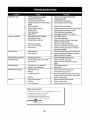
Enginefailstostart
Enginerunserratically
5,
1.
PTO/BladeEngageleverengaged.
2.
Parkingbrakenotengaged.
3,
Sparkplugwire(s)disconnected.
Throttlecontrollevernotin correctstarting 4.
position.
Chokenotactivated
5.
6.
7.
Fueltankempty,or stalefuel.
Blockedfuelline.
8.
9.
Faultysparkplug(s).
Engineflooded.
1.
2.
3.
4.
6.
7.
8.
1, Unit runningwithCHOKEactivated.
2. Sparkplugwire(s)loose.
3. Blockedfuellineor stalefuel.
Placeleverin disengaged
(OFF)position.
Engageparkingbrake.
Connectwire(s)tosparkplug(s).
Placethrottleleverto FASTposition.
Pullthe CHOKEcontrol outward.
Filltank with clean, fresh (less than 30 days old) gas,
Replacethe fuel line and replacefuel filter.
9.
Clean, adjust gap or replace plug(s).
Crank engine with throttle in FAST position.
1.
Push CHOKEcontrol in.
2.
3.
Connect spark plug wire(s),
Replacethe fuel line; fill tank with clean, fresh
gasoline and replacefuel filter.
4.
Vent in gas cap plugged.
4.
Clear vent or replacecap if damaged,
5.
Wateror dirt infuel system,
5,
6.
Dirty air cleaner.
6.
Drain fuel tank, Refill with clean, fresh gasoline.
Replaceair cleanerpaper element or clean foam
pre-cleaner,if equipped.
1. Engineoil levellow.
2. Air flow restricted.
1.
Fill crankcase with proper amount and weight of oil.
2,
Clean grass clippings and debris from around the
engine's coolingfins and housing,
Enginehesitatesat highRPM
1. Sparkpluggaptooclose.
1.
Removespark plug and reset the gap.
Engineidlesrough
1. Sparkplugfouled,faultyor gaptoowide.
2. Dirtyair cleaner.
1.
2,
Replacespark plug. Set plug gap,
Replaceair cleaner elementand/or clean precleaner.
Engineoverheats
Excessivevibration
Mowerwillnotmulchgrass
Unevencut
1.
2,
1.
Cutting blade loose or unbalanced,
2.
Damaged or bent cutting blade.
Tighten blade and spindle.
1.
Engine speedtoo low.
1.
2.
Wet grass,
3.
Excessively high grass.
2,
3,
4.
Dull blade.
4.
Sharpenor replace blade,
1.
2.
Deck not leveledproperly.
Dull blade,
1.
2.
Performside-to-side deck adjustment.
Sharpenor replace blade,
3,
Uneventire pressure.
3,
Check tire pressure inall four tires.
Replace blade.
Place throttle in FAST(rabbit) position.
Do not mulchwhen grass is wet.
Mow once at a high cutting height, then mow again
at desired height or make a narrower cutting swath,
NEED MORE HELP?
You'll find the answer and more on managernyl_orne.corn
• Find this and all your other product
• Get answers
manuals
online.
from our team of home experts.
• Get a personalized
• Find information
maintenance
plan for your home.
and tools to help with home
manage_horne
b_ought
to yo_ by Sears
28
projects.
• for free!
777S32491
REF: 751 B278856
777X43688
_lH_lP%ErdUl]
777D14479
REE 777D14476 (QTY 3)
777122773
i......... )
oPE_noasuusl_
777122453
777D14483
777X44381
Center Below Seat
777D14482
(QTY2)
777123092
777S30018
777D14489
777S30503
777122454
777122455
i=
/
29
777122456
_'_...... ::7
CraftsmanModel247.28902
8
/
22
/21
15
10
12
/
34
42
/
44
45
@
/
41
3O
11
CraftsmanModel247.28902
Ref.
No. [
1
i
Part No.
925-1649
Part No.
Des¢ription
Descri ption
Bulb Socket
711-0736
Ferrule, 1/4-20 x 1.00
683-04619-4043
Hood Assembly
712-04065
Nut, Hex Flange Insert Lock, 318-16
710-04484
Screw, 5/16-18 x .750
714-04040
Cotter Pin
710-0599
Hex Washer Screw, I14-20 x .500
936-0133
Flat Washer, .411 x 1.25 x .100
712-0292
Tin Clip Nut, I/4-20
750-04465
Flange Spacer
710-0751
Hex Screw, I/4-20 x .620
783-04862
Speed latch
710-05108
Screw, 114x .750
710-0604A
Self-Ta p Screw, 5/16-I 8
712-04064
Nut, Hex Flange Insert Lock, I/4-20
710-0895
Hex Screw, 114-15
731-07668
Grill
712-04063
Nut, Hex Flange Lock, 5/16-18
10
731-07458
Headlight
731-04945
Steering Support
11
731-07459
Headlight Lens, LH
783-04892B-0637
Dash
12
731-07460
Dash Collar
683-04448-0637
Battery Assembly Rod
13
731-07670
Hood Scoop, LH
726-0230
Cable Tie
14
731-07669
Hood Scoop, RH
747-04430
Speed Selector Control Rod
15
735-0271A
Bumper
751-0555B
1.5 Gallon Fuel Tank
16
738-04091A
Shoulder Screw, 5116-18
751-0603A
Fuel Cap
17
783-05327B-0637
Left Support
783-04584#,-0637
Gas Tank Support Bracket
18
783-05328A-0637
Right Support Pivot Bracket
731-05265
Choke Plug
19
783-06598-4043
Lower Grill
746-04364
ThrottlelChoke
20
783-06610-0637
Lower Grill Bracket
725-04992
Key Switch Module
21
983-04226
Speed Selector, 7-Speed
625-04124
Key (2 pack)
22
710-04483
Self-Tap Screw, I/4-20
725-0157
Cable Tie
23
710-3144
Hex Head Screw, 318-16
925-0963
Headlight
Lens, RH
Pivot Bracket
31
Bulb
Assembly
CraftsmanModel247.28902
2\
\
_15
\
\
22
2o
3o
14
45
29
32
Craftsman
Model 247.28902
Ref.
No.
I
Part No.
"°"1
No.
Description
Part No,
I
Description
1
683-04155A-0637
Shaft,Lift
24
756-04196A
2
712-04065
Nut,HexFlangeInsertLock,3/8-16
25
747-04857
BeltKeeperRodAssembly
3
714-04040
Bow-TiePin,91,RH
26
710-04484
Screw,Hd.Tapp,5/16-18x 75
4
716-0106A
E-ring,,625Shaft
27
683-04195-0637
SupportBracketAssembly
5
720-0311
Grip,Handle
28
683-04601-0637
RiderFrameAssembly
I Engagement
Pulley
6
732-04225
Spring,Lift HandleTorsion
29
7
738-04130
Bolt,Shoulder,.625x .175:3/8-16
30
710-3008
Screw,Hx.Hd.,5/16-18x .75
8
941-0225
Bearing,HexFlange,
31
712-04063
Nut,HexRangeInsertLock,5/16-18
9
747-05296
Handle,Lift
32
712-04064
Nut,HexRangeInsertLock,1/4-20
lO
747-04393
LiftRod,13.68
33
912-0429
HexlockNut,5/16-18
11
783-04494C-0637 Arm,DeckLift RH
34
732-04035
Spring,Compress.,1.28x 3.125
Arm,DeckLift LH
35
736-0173
FlatWasher,.28x .74x .063
12
647-04096-0637
PTOHandleAssembly
36
783-04548C-0637 SeatBracketFrame
13
710-04608
Screw,Hx.Hd.,7/16-20x 3.25
37
783-04637-0637
RunningBoardBracket
14
710-0599
Screw,Hd.Tapp,1/4-20x .5
ClickPin
38
783-04753-0637
FrameSupportBracket
39
783-04869A-0637
783-05389A-0637
FrameBraceBracket
783-0471tC-0637
1710-0134
CarriageScrew,1/4-20x .62
15
714-04040
16
720-04049A
HandleGrip
40
17
732-04276A
PTOSpring,Extension
41
725-05090
DieHardBattery
18
936-0171
Washer,Flat, 7/16
42
738-t132
Screw,Shoulder,.250x .150
19
736-0322
Washer, Flat, .450 x .250 x .164
43
712-0271
Nut,Seres,1/4-20
20
738-04237A
Shoulder Screw,#10-32 x .500
44
683-04448-0637
BatteryRod
21
741-04119A
PTOBearing
45
925-04039
ScrewMountInterlockSwitch
22
946-04173B
DeckEngagementCable
46
725-04363
InterlockSwitch
23
725-04439
12v.Solenoid
33
BatteryBracket
Craftsman
Model 247.28902
i
1
21
34
Craftsman
No.
Model 247.28902
Part No.
Description
No.
ReL
I
Description
Part No.
1
617-04024
Gear Assembly, Steering
23
938-04007A-0637
Axle Assembly LH
2
710-0376
Screw, 5/16-18,1.00, GrS
24
638-04008P
Axle Assembly RH
3
710-0643
Screw, 5/16-18,1.00, Gr5, Lock
25
683-0128B-0637
Pivot Bar Axle Assembly
4
710-1309
Screw, Mach, 5/16-18, 0.750
26
710-04484
Screw, 5116-18, 0.750
S
710-3180
Screw, 5/16-18,1.7.5, GrS
27
712-04065
Nut, Flange Lock, 3/8-16, GrF
6
912-0240
Nut, Jam, 7/16-20, Gr2
28
i 714-04039
Pin, Cotter, 5/32, 1.25
7
912-0214
Nut, Jam Lock, 3/8-24
29
914-0474
Pin, Cotter, I/8 x 0.7.5
8
712-04063
Nut, Flange Lock, 5116-18, Grf
30
736-0341
Push Cap, 3/4
9
931-0484A
Hub Cap
31
731-04057A
Axle Cap
10
923-0448A
Ball Joint, 7/16-20, Lock
32
736-04228A
Washer, Flat, .781 x 1.59
11
736-0242
Washer, Bell, .340 x .872 x .060
33
738-04128
Screw, Shlder, .500 x 2.380, 3/8-16
12
934-0255
Valve Stem
34
741-0660A
Flange Bearing
13
738-04141
Shoulder Screw, 5116-18
35
747-04299A
Tie Rod
14
738-0919A
Steering Shaft, 518 Spline x 21.86
36
783-05326B-0637
Pivot Bar Bracket
15
941-04124
Bearing, Flange, Hex 518
37
631-04028
Steering Wheel, Standard Grip
16
941-04454
Plastic Bushing .375 ID x .OSOD
38
731-06825
Cap, Steering Wheel (Crafts. logo)
17
747-04298
Drag Link, Steering
39
634-04086-0961
Wheel Assembly
18
948-0389
Cap, 1.25 x .16
40
934-04081-4042
Rim
19
748-04065-0637
Steering, Block
41
734-1731-0901
Tire, 15 x 6 x 6 Sq. Shoulder
20
748-04068
Spacer, .710 ID x .125 OD x .56
42
741-0990B
Flange Bearing
21
750-04418
Spacer, .322 ID x .625 OD x .21
43
741-0516B
Flange Bearing
22
783-04644
Stabilizer Plate, Gear Segment
35
CraftsmanModel247.28902
2O
22
31 30
32
34
29
/
36
\
36
Craftsman
Model 247.28902
Ref.
No.
1
I
Part No.
Description
I
710-1268
Screw, #10-16 x .375
2
712-04063
Flange Lock Nut, 5/16-18
3
712-04064
Flange Lock Nut, I/4-20
4
720-0309A
Seat Adjustment
5
726-0201
Speed Nut
6
731-04074
Seat Adjustment
7
732-0499
Compression Spring, .41 x 1.50
8
732-1184
Extension Spring
9
736-0204
Flat Washer, .344 x .62 x .033
10
736-0242
Flat Washer, .340 x .872 x .060
11
736-3019
Flat Washer, .531 x .062 x .134
12
938-0137A
Shoulder Screw, .34 x .285:I14-20
13
938-0296
Shoulder Screw, 5116-18x .437x .268
14
738-0966A
Shoulder Bolt, .50 x .925:3/8-16
15
783-0209D
Grip
Spacer
Lift Seat Bracket
16
783-0611
Seat Adjustment
17
783-O738D-0637
Seat Pivot Bracket
18
783-0739A-0637
Seat Adjustment
Lever
19
783-0753
Seat Adjustment
Selector
20
757-04125
Low Back Seat
21
710-04483
Screw, I/4-20 x .500
22
710-04484
Screw, 5/16-18 x .750
23
710-0599
Screw Pan Torx Head, I/4-20 x .500
24
731-04591A
Cup Holder
25
736-0607
Lock Washer, 5116
26
783-04587C-4043
Fender
27
783-04843-0637
Lift Adjuster Bracket
28
783-1489C-0637
Seat Mounting
29
735-04047
Rubber Foot Pad, LH
735-04048
Rubber Foot Pad, RH
30
710-0227
Screw, 8-18 x.500
31
726-0279
Insulator Plate
32
925-1303
Outer Seat Spring
33
726-0278
Insulator Boss Plate
34
725-1439
Inner Seat Spring
35
710-0134
Carriage Screw, .62:I/4-20
36
726-04072A
Ratchet Clip, .250 x .500
37
Stop Bracket
Bracket
CraftsmanModel247.28902
38
Craftsman
Model 247.28902
!
Ref. I
Part No.
J
Description
1
683-04_9-0637
Muffler Shield Assembly
2
710-0227
Screw, AB #8-18 0.500
3
710-04683
Tap Screw, 3/8-16 1.000
4
710-0642
Tap Screw, 1/4-20 0.750
5
710-1314A
Screw, Socket Head, 5/16-18 x .750
6
712-0271
Seres Nut, 1/4-20
7
BS-692236
Exhaust Gasket
8
725-0157
Cable Tie, 3/16 X .05 X 7.4
9
726-0205
Hose Clamp, .490 Dia.
lO
728-04000
Pop Rivet, .188 Dia X .300 L
II
731-05628
Oil Drain Sleeve
12
75%05648
Muffler
13
751-I0349
Low Permeation
14
751-I0353
Long Muffler Deflector
15
751-I04488
Briggs Single Muffler
i
39
Deflector
Fuel Hose, 1/4
CraftsmanModel247.28902
7
61
27
38
23
p
4O
Craftsman
Ref"
No. I
Model 247.28902
PartN°"
Ref.
No.
Description
I
I
918-04566
Transmission
2
647-0403400637
3
647-04035
4
710-0227
5
I
Part No.
Description
33
747-05188
Brake Rod
Pedal Assembly
34
747-05243
Shift Rod, 46"
Shaft Lever Assembly
35
948-0334
Spacer, T-Axle
Screw, 8-I 8:0.500
36
750-0566A
Spacer, .260 x .375 x 1.O30 LG
710-04484
Screw, 5/16-18 x .750
37
750-0802
Spacer, .640 ID x .76 OD x 2.63
6
710-0599
Screw, I/4-20 x 0.500
38
954-04249
V Belt, 5L: 70.90 POLY
7
710-0604A
Screw, 5/16-18 x 0.625
39
954-04265
V Belt, 5L: 33.8 POLY
8
710-0809
Screw, I/4-20 x 1.250
40
756-04432
Trans. Pulley
9
710-1266
Hex Screw, 5/16-18 x .625
41
783-04536B-0637
Pedal Support Bracket
10
710-3008
Hex Screw, 5/16-18 x .75
42
783-04595A
Shaft Adjust Bracket
11
911-04075A
Ferrule, 3/8-24 X .375 DIA.
43
956-O4015A
Variable Speed Pulley Assembly
12
712-04063
Flangelock Nut, 5/16-18
44
683-04206
Bracket Assembly
13
712-0700
Flange Nut, 9/16-I 8
45
710-0627
Hex Screw, 5/16-24 x .750
14
914-0209
Cotter Pin INT-.125 DIA
46
710-0778
Screw, I/4-20 x 1,500
15
714-04040
Bow-Tie Cotter Pin
47
718-04261
Bearing Cup
16
718-04407
Pulley Hub, 518 SPLINE
48
736-0362
Flat Washer, .330 x 1.25 x .06:HT
17
720-04028
Shift Knob
49
941-0600
Ball Bearing, 17 x 40 x 12
18
725-0157
Cable Tie
50
683-04176A
Transmission
19
725-1644
Short Spring Switch
51
753-05147
Idler Bracket Assembly
20
726-0214
Push Cap, 518
52
710-0347
Hex Screw, 318-16 x 1.75
21
926-0320
Plate Insulator Nut
53
710-1260A
Screw, 5/16-18 x 0.750
22
731-04602
Sleeve, .758 x .821 x 3.3125
54
712-04065
Flange Lock Nut, 3/8-16
23
731-04604
Sleeve, .758 x .821 x 2.4375
55
938-0347
Shoulder Spacer, .625 ID x .169
24
731-06894
Shift Bearing Plate
56
756-04325
Idler Pulley
25
732-04306
Spring Extension, .80 OD x 3.28 LG
57
725-04363
Switch Interlock
26
732-04488
Spring Extension, .38 OD x 3.25 LG
58
17962
Plate Switch
27
732-0459C
Spring Extension, .94 OD x 6.74 LG
59
738-04237A
Shoulder Screw, #10-32 x .500
28
732-0716D
Spring Extension,.59
60
634-04641-0961
Wheel Assembly, 18 x 9.5 x 8 Sq. Sh.
29
735-0239
Foot Pad, 4.0 LONG
61
634-04369-4042
Rim Assembly
30
736-0242
Bell Washer, .340 x .872 x .060
62
934-0255
Valve Stem
31
747-04969
Belt Keeper Rod
63
734-1729
Tire, 18x9.5 x8 Sq. Sh.
32
747-05186
Variable Speed Control Rod
925-04085
Wiring Harness (NotShown)
Drive Assembly
[
OD x 4.00 LG
41
Bracket Assembly
Craftsman
Model 247.28902
42
Craftsman
Model 247.28902
Ref.
No.
I
Part No.
1
918-04822A
2
683-0254B-0637
3
956-1227
4
983-04511
I
FSpindle
Description
ReL
No. II
Part No.
I
Description
,
29
736-0262
Flat Washer, .385 x .870 x .092
Deck Hanger Bracket Assembly
30
736-0362
Flat Washer, .330 x 1.25 x .06
Spindle Pulley
31
738-04146
Bolt Plug, M16 x 1.5
Brake Assembly
32
738-04i62A
Shoulder Spacer, .8840 x .190
Pulley Assembly
5
983-04525
Brake Assembly
33
738-04166
6
983-04572-0637
Deck
34
942-04308
Cutting Blade, 2!.23": 2 in I
7
710-04484
Screw, 5116-18 x .750
35
747-04530
Belt Keeper Rod
8
710-0514
Screw, 3/8-16 x 1.00
36
747-049448
Deck Lift Rod
9
710-O528
Hex Screw, 5/16-18 x 1.25
37
747-05105
Brake Control Rod
10
710-0599
Screw, I/4-20 x .S00
38
748-04069
Deck Lift Pivot Cup
11
710-O778
Screw, I/4-20 x 1.50
39
750-0258
Spacer
12
710-0809
Screw, I/4-20 x 1.250
40
750-0566A
Spacer
13
710-3144
Hex Head Screw, 3/8-16
41
954-04060B
V-Type Belt, 96.5
14
710-3178
Carriage Bolt, 3/8-16 x .75
42
756-04129B
Idler Pulley, 4.25 Diameter
15
712-0229
Push Nut, 3/8
43
783-05946
Idler Pivot Bracket
16
712-04063
Flangelock Nut, 5116-18
44
783-06243-0637
Deck Cable Engagement
17
712-O4065
Flangelock Nut, 318-16
45
783-06368-0637
18
712-0417A
Flange Nut, 5/8-18
46
783-06424A-0637
Deck Belt Cover
19
712-04243
Flangelock Nut, I12-13
47
783-06643-0637
Deck Support Bracket
20
912-0641
Hex Nut, M16- 1.S
48
631-04460
Chute Deflector Assembly
21
714-O4043
Cotter Pin, Bow-Tie
49
711-O4847A
Hinge Pin
22
917-O4074
Deck Adjuster Gear
50
732-04372
Torsion Spring, .44 x 2.0
23
932-0384
Extension Spring, .62 x 6.12
51
783-06074A
Chute Bracket
24
732-04727
Torsion Spring, 1.0 x 1.17
52
936-O351
Flat Washer, .760 x 1.50
25
936-0119
Lock Washer, 5116
53
738-1186A
Spindle Shaft
26
936-0176
Flat Washer, .265 x 9.38 x .120
54
941-0919
Ball Bearing, .787 x 1.85 x .S51
27
736-O187
Flat Washer, .64 x 1.24 x .06
55
750-04936
Spacer, .792 x 1.060 x 1.860
28
736-0225
Flat Washer, .518 Int. Tth.
43
_ Shoulder Spacer,.5000
.
x .1475
Bracket
Belt Pulley Guard
Craftsman
Model 247.28902 with Engine Model 31P677-1373-B2
585
1264
126_._.2
616
45 #/,_Z"
_ _
Io24T "-_ .......
b............
r "_
i
i
[
_.,d
i
[
:3_:="_,
i
1027
@_d_
1965
943
750
44
g
Craftsman
Model 247.28902 :with Engine Model 31P677-1373-B2
45
1o26j.
f
d/_
1026A
1022
635 k_
02"_
.,_022
617 _
/_
_'
',,._i._
914 _
_-._
51A/
85O
186
..-")
54
654
@
45
Craftsman
Model 247.28902 with Engine Model 31P677-1373-B2
I
127
t@
105
%
654
@
k.........
276 _
i'<"
i
_J
_J
I
\..:_;j
1127
/o_
.o
s
\
_._j_
1266 _k!.,"
46
Craftsman
Model 247.28902 with Engine Model 31P677-1373-B2
1040
305
305A
305B
J
1070
1005
lo44
78 _--_.._/_
..........
/__.'-.,_\
_fii}'b'_i__,_i
_oslo /
_'
783 '_"_/
47
_7_
._
_,
Craftsman
Model 247.28902 with Engine Model 31P677-1373-B2
1119
,o_
_7
510 _ 1051
G
I O54
P
C_..>
783 _)
310 (
8O3
729
9
_o_(_j_
697
188
_)
222
209
265_
267
48
Craftsman
Model 247.28902 with Engine Model 31P677-1373-B2
121 CARBURETOR OVERHAUL KIT
51_
1270
987 0
6170
lO4 /_
1266 <_
io5
3@
1095 VALVE GASKET SET
51_:-% 1022_
868 _."
49
,',
...
Craftsman
Model 247.28902 with Engine Model 31P677-1373-B2
796010
Cylinder
2
399265
Kit-Bushing/Seal
Assembly
(Magneto
(Magneto
Side)
Kit-Idle
694918
Pin-Float
105
696136
Valve-Float
108
695419
Valve-Choke
117
699773
Jet-Main
(Standard)
118
843099
Jet-Main
(High Altitude)
Speed
Hinge
Needle
3
391086s
Seal-Oil
4
795993
Sump-Engine
5
796026
Head-Cylinder
7
796584
! Gasket-Cylinder
11
794683
Tube-Breather
121
796184
Kit-Carburetor
12
697110
Gasket-Crankcase
125
796110
Carburetor
13
793988
Screw (Cylinder
127
690727
Plug-Welch
15
690946
Plug-Oil
130
792747
Valve-Throttle
16
797759
Crankshaft
131
792765
Kit-Throttle
20
795387
Seat-Oil
133
694914
Float-Carburetor
22
692125
Screw (Crankcase
135
I 698780
698281
Flywheel
222698s
Key-Flywheel
28
Cover/Sump)
135A
Piston Assembly
(Standard)
796173
Piston Assembly
(.020" Oversize)
791936
Ring Set (Standard)
698469
796007
(Service
Carburetor)
Shaft
Tube-Fuel
Transfer
(Original
792022
Tube-Fuel
Transfer (Service
Carburetor)
137
Ring Set (.020" Oversize)
Lock-Piston
Overhaul
Carburetor)
796172
792649
27
Head)
(PTO Side)
24
26
Head
Drain
23
25
Side)
695408
104
Pin
Pin-Piston
698781
Gasket-Float
Bowl
141
792777
Kit-Choke
146
691639
Key-Timing
186
794873
Connector-Hose
791805
Line-Fuel
187
Shaft
(Intake Manifold)
(Formed)
(Cut to required
length)
29
794122
Rod-Connecting
32
33
791118
792868
Screw (Connecting
Valve-Exhaust
34
791935
Valve-Intake
35
691279
Spring-Valve
(Intake)
36
691279
Spring-Valve
(Exhaust)
37
: 697352
42
499586
Keeper-Valve
43
691968
Slinger-Governor/Oil
45
46
690564
793880
Tappet-Valve
Camshaft
48
697762
Short
Rod)
Guard-Flywheel
691693
Screw (Control
691986
Adjuster-Rocker
Arm
202
691841
Link-Mechanical
Governor
209
692208
i Spring-Governor
(Green)
216
691840
Link-Governor
217
695409
Spring-Choke
222
694042
Bracket-Control
227
691374
Lever-Governor
Control
232
691842
Spring-Governor
Link
238
691843
Cap-Valve
240
394358s
Filter-Fuel
265
691024
Clamp-Casing
267
794904
Screw (Casing
276
695410
Washer-Sealing
304
797900
Housing-Blower
305
697102
Screw (Blower
Bracket)
Return
Block
50
796180
Manifold-Intake
51
51A
692137
796081
Gasket-Intake
Gasket-Intake
53
690227
Stud (Carburetor)
54
691148
!Screw
78
691003
i Screw (Flywheel
94
793610
95
690718
Kit-Idle
188
192
(Intake Manifold)
Housing
Guard)
Mixture
i Screw (Throttle
Valve)
Clamp)
Housing) (Blower
to Cylinder)
(1/4-20x1,14)
305A
793376
Screw (Blower
Housing)
(1/4-20x.68)
305B
795891
Screw (Blower
Housing)
(To
Carburetor
Elbow) (#10-16x.43)
• Includedin Engine GasketSet, Key Number358.
(_ Includedin Carburetor OverhaulKit, Key Number 121.
+ Includedin Valve Gasket Set, Key Number 1095.
5O
Craftsman
Model 247.28902 with Engine Model 31P677-1373-B2
796006
Shield-Cylinder
691909
3O7
691003
Screw (Cylinder
Boot-Spark
643
698401
Retainer-Air
309
693551
Motor-Starter
654
690958
310
690323
i Screw (Starter
Nut (Carburetor)
Motor)
684
697157
Screw
324
796308
Screen/Cup
Assembly
691
692407
Seal-Governor
333
697
690372
Screw (Drive Cap)
718
690959
Pin-Locating
Clip-Wire
Shield)
Plug
Filter
(Breather
795315
Armature-Magneto
334
691061
Screw (Magneto
337
491055s
Plug-Spark
729
691224
358
794150
Gasket Set-Engine
741
1697128
4O4
691691
Washer
750
790832
757
_793242
758
793763
759
697392
Pin-Counterweight
783
693713
Gear-Pinion
789
698329
Harness-Wiring
693167
Nut (Brush
415
415A
794129
690283
Armature)
(Governor
Crank)
Plug (Cover/Retainer)
i Plug (Intake
Manifold)
431
797901
Elbow-Intake
445
796031
Filter-Air
462
691261
Washer (Starter
474
696459
Alternator
797
5O3
691532
Strap-Starter
801
5O5
691251
Nut (Governor
510
693699
Drive-Starter
513
692024
Clutch-Drive
Cleaner
699908
Dipstick
691032
Seal-Dipstick
697184
544
Control
Lever)
Tube
, Tube-Dipstick
Armature-Starter
(Order Starter
Motor 693551, Reference
552
697144
Bushing-Governor
562
691119
Bolt (Governor
579
691029
Nut (Starter
584
585
794682
697109
802
[691283
691286
Screw (Oil Pump Cover)
Link-Counterweight
Counterweight
Cap-Drive
Cap-End
,830
Stud-Rocker
842
691031
Seal-O
847
790442
Dipstick/Tube
850
100106
Sealant-Liquid
Ring (Dipstick
with Rocker Cover
Breather
Lever)
851
.....
868
Passage
and
(Breather
Reference
850, are
692424
690968
Terminal-Spark
Plug
Seal-Valve
877
i790544
Wire/Connector-Alternator
883
1692236
Gasket-Exhaust
914
697551
Screw (Rocker
943
690589
SeaI-O
947
699915
Solenoid-Fuel
965
499613
Cover-Oil
Pump
968
797902
Cover-Air
Cleaner
975
699502
Bowl-Float
987
698777
Seal-Throttle
1005
796083
Fan-Flywheel
1017
796981
Screen-Oil
:601
791850
Hose-Clamp
614
691620
Pin-Cotter
616
692012
Crank-Governor
617
692138
SeaI-O Ring (Intake Manifold)
(Green)
(Governor
Passage
Gasket)
interchangeable)
Liquid Sealant,
Tube)
Assembly
Gasket and/or
Passage
Gasket-Breather
Passage Gasket
309)
Arm
(Interchangeable
Cable)
Cover-Breather
(Order Starter Motor
Reference
691095
Crank
Control
Retainer)
Housing-Starter
309)
Crank)
Cover)
Ring (Oil Pump Cover)
, ,,,,
633
699813
Seal-Choke/Throttle
(Red)
Shaft (Choke
Shaft)
634
698779
Spring/Seal
Assembly
Cover)
Gear-Timing
693551,
524
525
Cable)
803
523
,,,,,, ,, ,
Cartridge
Passage
Shaft
(Choke Shaft)
Shaft
Pump
• Includedin Engine GasketSet, Key Number 358.
0 Included in CarburetorOverhaul Kit, Key Number 121.
+ Includedin Valve GasketSet, Key Number 1095.
51
This page intentionally
left blank. Use this page to make any notes regarding your tractor.
52
This page intentionallyleft blank.Usethis pageto makeany notesregardingyour tractor.
53
Look For Relevant Emissions Durability Period and
Air Index Information
On Your Engine
Emissions
Label
Engines that are certified to meet the California Air Resources Board (CARB) Tier 2 Emission Standards must
display information regarding the Emissions Durability Period and the Air Index. Sears Brands Management
Corporation makes this information available to the consumer on our emission labels.
The Emissions Durability Period describes the number of hours of actual running time for which the engine is
certified to be emissions compliant, assuming proper maintenance in accordance with the Operating & Maintenance Instructions. The following categories are used:
Moderate:
Engine is certified to be emission compliant for 125 hours of actual engine running time.
Intermediate:
Engine is certified to be emission compliant for 250 hours of actual engine running time.
Extended:
Engine is certified to be emission compliant for 500 hours of actual engine running time.
For example, a typical walk-behind lawn mower is used 20 to 25 hours per year. Therefore, the Emissions
Durability Period of an engine with an intermediate rating would equate to 10 to 12 years.
The Air Index is a calculated number describing the relative level of emissions for a specific engine family. The
lower the Air Index, the cleaner the engine. This information is displayed in graphical form on the emissions label.
After July 1, 2000, Look
On Engine
For Emissions
Emissions
Compliance
Compliance
Period
Label
After July 1, 2000 certain Sears Brands Management Corporation engines will be certified to meet the United
States Environmental Protection Agency (USEPA) Phase 2 emission standards. For Phase 2 certified engines, the
Emissions Compliance Period referred to on the Emissions Compliance label indicates the number of operating
hours for which the engine has been shown to meet Federal emission requirements.
For engines less than 225 cc displacement, Category C = 125 hours, B = 250 hours and A = 500 hours.
For engines of 225 cc or more, Category C = 250 hours, B = 500 hours and A = 1000 hours.
This isa genericrepresentationof the emissionlabeltypicallyfound ona certifiedengine.
FAMILY:YBSXS.501L_P
274826
3192VA
GDOC-100182 Rev.B
54
(This page applicable in the U.S.A. and Canada only.)
Sears Brands
Emission
Management Corporation (Sears), the California Air Resources Board (CARB)
andthe United States Environmental
Protection Agency (U.S, EPA)
Control System Warranty Statement (Owner's Defect Warranty Rights and Obligations)
EMISSIONCONTROL
WARRANTY
COVERAGEISAPPLICABLE
TOCERTI,
FlEDENGINESPURCHASED
INCALIFORNIA
IN 1995ANDTHEREAFTER. WHICHAREUSEDIN CALIFORNIA,
ANDTOCERTIFIED
MODEL
California
and United States Emission
YEAR1997ANDLATERENGINES
WHICHAREPURCHASED
ANDUSED
ELSEWHERE
INTHEUNITEDSTATES
(ANDAFTERJANUARY
1,2001IN
CANADA).
Control Defects Warranty
Statement
TheCaliforniaAirResourcesBoard(CARB),U.S.EPAandSearsarepleased
engineforthe periodsof timelistedbelow,providedtherehasbeenno abuse,
to explainthe EmissionControlSystemWarrantyon yourmodelyear2000and
neglector impropermaintenanceofyoursmalloff,roadengine.Youremislatersmalloff-roadengine(SORE).InCalifornia,newsmalloff-roodengines
sioncontrolsystemincludespartssuchasthe carburetor,airCleaner,ignition
must bedesigned,builtandequ!ppedto meetthe State'sstringentanti-smog
system,mufflerandcatalyticconverter.
Alsoincludedmaybeconnectorsand
standards.Elsewhere
inthe UnitedStates,newnon-road,spark-ignition
otheremissionrelatedassemblies.
Whereawarrantableconditionexists,Sears
enginescertifiedformodelyear1997andlatermustmeetsimilarstandardsset will repairyoursmalloff-roadengineat nocostto youincludingdiagnosis,parts
andlabor.
forth bythe U.S.EPA.SearsmustwarranttheemissioncontrolSystemonyour
Sears Emission Control Defects Warranty Coverage
Small off-roadenginesarewarrantedrelativeto emissioncontrolpartsdefects
fora periodof oneyear,subjectto provisionssetforthbelow.Ifanycovered
Owner's Warranty
parton yourengineis defective,
the part willbe repairedor replacedbySears.
Responsibilities
Asthe smalloff-roodengineowner,you areresponsible
forthe performance
of
the requiredmaintenancelistedinyourOperatingandMaintenanceInstructions.Searsrecommends
thatyou retainallyourreceiptscoveringmaintenance
on yoursmalloff-roadengine,but Searscannotdenywarrantysolelyforthe
lackof receiptsor foryourfailureto ensurethe performanceof allscheduled
maintenance.
Asthe smalloff-roadengineowner,youshouldhoweverbe
awarethatSearsmaydenyyouwarrantycoverageif yoursmalloff-roodengine
or a parthasfaileddueto abuse,neglect,impropermaintenance
or unap-
provedmodifications.
Youareresponsible
forpresentingyoursmalloff-road
engineto an AuthorizedSearsServiceDealerassoonasa problemexists.The
undisputedwarrantyrepairsshouldbe completedin a reasonableamountof
time,notto exceed30days.If youhaveanyquestionsregardingyourwarranty
rightsandresponsibilities,
youshouldcontacta SearsServiceRepresentative
at 1-800-469-4663.
Theemissionwarrantyis adefectswarranty.Defectsare
judgedon normalengineperformance.The
warrantyisnot relatedto an in-use
emissiontest.
Sears Emission Control Defects Warranty Provisions
Thefollowing
arespecific
provisions
relative
toyourEmission
Control
Defects
Warranty
Coverage,
Itisin addition
totheSearsengine
warranty
fornon-regulated
enginesfoundinthe OperatingandMaintenance
Instructions.
1. WarrantedParts
3. NoCharge
Repairor replacementof anyWarrantedPartwillbe performedat no
chargetothe owner,includingdiagnosticlaborwhichleadsto the
determinationthata WarrantedPartisdefective,if thediagnosticworkis
performedat an AuthorizedSearsServiceDealer.Foremissionswarranty
servicecontactyournearestAuthorizedSearsServiceDealeras listedin
the "YellowPages"under"Engines,Gasoline,""GasolineEngines,""Lawn
Mowers,"or similarcategory.
4. ClaimsandCoverageExclusions
Warrantyclaimsshallbefiled inaccordancewiththe provisionsof the
SearsEngineWarrantyPolicy.Warrantycoverageshallbe excludedfor
failuresofWarrantedPartswhicharenotoriginalSearspartsor because
of abuse,neglector impropermaintenanceassetforth inthe Sears
EngineWarrantyPolicy.Searsis notliableto coverfailuresof Warranted
Partscausedbythe useofadd-on,non-original,
or modifiedparts.
5. Maintenance
Coverageunderthiswarrantyextendsonlyto the partslistedbelow(the
emission
controlsystemsparts)to the extentthesepartswerepresenton
the enginepurchased.
a. FuelMeteringSystem
• Coldstartenrichmentsystem
• Carburetorandinternalparts
• FuelPump
b. Air InductionSystem
• Aircleaner
• Intakemanifold
c. IgnitionSystem
°Sparkplug(s)
• Magnetoignitionsystem
d. CatalystSystem
• Catalyticconverter
• Exhaustmanifold
• Airinjectionsystemor pulsevalve
e. Miscellaneous
ItemsUsedin AboveSystems
• Vacuum,temperature,position,timesensitivevalves
andswitches
• Connectorsandassemblies
2. Lengthof Coverage
Searswarrantsto the initialownerandeachsubsequentpurchaserthat
the WarrantedPartsshallbe freefromdefectsinmaterialsandworkmanshipwhichcausedthe failureof the WarrantedPartsfora periodof one
yearfromthedatethe engineis deliveredto a retailpurchaser.
AnyWarrantedPartwhichis notscheduledfor replacement
as required
maintenanceor whichisscheduledonlyfor regularinspectionto the effect
of"repairor replaceasnecessary"shallbe warrantedasto defectsfor the
warrantyperiod.AnyWarrantedPartwhichisscheduledforreplacement
asrequiredmaintenanceshallbe warrantedasto defectsonlyforthe
periodoftime upto the firstscheduledreplacement
for thatpart.Any
replacement
partthatis equivalentinperformanceanddurabilitymay
be usedinthe performanceof anymaintenance
or repairs.Theowneris
responsibleforthe performance
of all requiredmaintenance,
asdefinedin
the SearsOperatingandMaintenanceInstructions.
6. Consequential
Coverage
Coveragehereundershallextendtothe failureofany enginecomponents
causedbythefailureof any WarrantedPartstill underwarranty.
IntheUSAandCanada,a 24 hourhotline,1-800-469-4663,
hasa menuof pro-recordedmessagesoffering
youenginemaintenanceinformation.
GDOC-100188
Rev.B
55
IIIrll
FEDERAL and/or CALIFORNIA EMISSION CONTROL WARRANTY STATEMENT
YOUR WARRANTY RIGHTS AND OBLIGATIONS
MTDConsumerGroupInc,the UnitedStatesEnvironmental
ProtectionAgency(EPA),and,forthoseproductscertified
forsaleinthestateof California,the
CaliforniaAir ResourcesBoard(CARB)are pleasedto explainthe emission(evaporative
and/orexhaust)controlsystem(ECS)warrantyon youroutdoor2006
andlatersmalloff-roadspark-ignited
engineandequipment(outdoorequipmentengine)InCalifornia,newoutdoorequipmentenginesmustbedesigned,builtand
equippedtomeetthe State'sstringentanti-smogstandards(inotherstates,1997andlatermodelyearequipmentmustbedesigned,built,andequippedto meet
the U.S.EPAsmalloff-road,sparkignitionengineregulations.MTDConsumerGroupIncmustwarrantthe ECSon youroutdoorequipmentengineforthe periodof
time listedbelowprovidedtherehas beenno abuse,neglector impropermaintenanceof outdoorequipmentengine.
YourECSmayincludepartssuchasthe carburetor,fuel-injectionsystem,the ignitionsystem,catalyticconverter,fueltanks,fuel lines,fuel caps,valves,canisters,
filters,vapor hoses,clamps,connectors,
andotherassociatedemission-related
components.
Wherea warrantableconditionexists,MTDConsumerGroupIncwill repairyouroutdoorequipmentengineat nocostto youincludingdiagnosis,partsandlabor.
MANUFACTURER'S WARRANTY COVERAGE:
Thisemissioncontrolsystemis warrantedfortwoyears.Ifanyemission-relatedpartonyouroutdoorequipmentengineisdefective,the partwill be repairedor
replacedbyMTDCONSUMERGROUPINC.
OWNER'S WARRANTY RESPONSIBILITIES:
Astheoutdoor
equipment
engineowner,youareresponsible
forperformance
oftherequired
maintenance
listedin yourowner'smanual,MTDConsumer
Group
Increcommendsthatyou retainall receiptscoveringmaintenanceon youroutdoorequipmentengine,but MTDConsumerGroupInccannotdenywarrantysolely
forthe lackof receipts.
Astheoutdoorequipmentengineowner,tou shouldhoweverbe awarethatMTDConsumerGroupIncmaydenyyou warrantycoverageif youroutdoorequipment
engineor a parthasfailed dueto abuse,neglect,or impropermaintenanceor unapprovedmodifications.
Youare responsiblefor presentingyouroutdoorequipmentengineto MTDConsumerGroupInc'sdistributioncenteror servicecenterassoonasthe problem
exists.Thewarrantyrepairsshouldbecompletedina reasonableamountof time,not toexceed30days.If youhavea questionregardingyourwarrantycoverage,
youshouldcontacttheMTDConsumerGroupIncServiceDepartmentat 1-800-800-7310
or viaemailat http://support.mtdproducts.com
GENERAL EMISSIONS WARRANTY COVERAGE:
MTDConsumerGroupIncwarrantstothe ultimatepurchaserandeachsubsequentpurchaserthatthe outdoorequipmentengineis: Designed,builtandequipped
soasto conformwithall applicableregulations;andfreefrom defectsinmaterialsandworkmanship
thatcausethe failureof a warrantedpartto beidenticalin all
materialrespectsto thatpartas describedin MTDConsumerGroupInc'sapplicationforcertification.
Thewarrantyperiodbeginson the datethe outdoorequipmentengineis deliveredto an ultimatepurchaseror first placedintoservice.Thewarranty
periodistwo
years.
Subjectto certainconditionsandexclusionsasstatedbelow,the warrantyon emission-related
Dartsis asfollows:
1. Anywarrantedpartthatisnot scheduledfor replacementasrequiredmaintenanceinthe writteninstructionssupplied,is warrantedforthe warrantyperiod
statedabove.Ifthe partfailsduringthe periodof warrantycoverage,the partwill be repairedor replacedbyMTDConsumerGroupIncaccordingto subsection
(4)below.Anysuch partrepairedor replacedunderwarrantywillbe warrantedforthe remainderof the period.
2. Any warrantedpartthatis scheduledonlyfor regularinspectioninthe writteninstructionssuppliedis warrantedforthe warrantyperiodstatedabove.Any such
partrepairedor replacedunderwarrantywiltbewarrantedforthe remainingwarrantyperiod.
3. Any warrantedpartthatis scheduledfor replacementasrequiredmaintenanceinthe writteninstructions
suppliedis warrantedforthe periodof timebeforethe
first scheduledreplacementdateforthatcart.Ifthe partfailsbeforethe first scheduledreplacement,
the partwill be repairedor replacedbyMTDConsumer
Grouplncaccordingto subsection(4)below.Anysuchpartrepairedor replacedunderwarrantywill be warrantedforthe remainderof the periodpriortothe
first scheduledreplacementpointforthe part.
4. Repairor replacementof anywarrantedpartunderthewarrantyprovisionshereinmustbe performedat awarrantystationatno chargetothe owner.
5. Notwithstandingthe provisionsherein,warrantyservicesor repairswillbe providedatall of ourdistributioncentersthatarefranchisedto servicethe subject
enginesor equipment.
6. Theoutdoorequipmentengineownerwill notbe chargedfor diagnosticlaborthatis directlyassociatedwithdiagnosisof a defective,emission.related
war.
rantedpart, providedthatsuchdiagnosticworkis performedata warrantystation.
7. MTDConsumerGroupIncis liablefor damagesto otherengineor equipmentcomponentsproximatelycausedbya failureunderwarrantyof anywarranted
part.
8. Throughoutthe off-roadengineandequipmentwarrantyperiodstatedabove,MTDConsumerGroupIncwill maintainasupplyofwarrantedpartssufficientto
meetthe expecteddemandforsuchparts.
9. Anyreplacementpartmaybe usedinthe performanceof any warrantymaintenanceor repairsandmustbe providedwithoutchargeto the owner.Suchusewill
not reducethe warrantyobligationsof MTDConsumerGroupInc.
10.Add-onor modifiedpartsthatarenotexemptedbythe Air ResourcesBoardmaynotbe used.Theuseof anynon-exempted
add-onor modifiedpartsbythe
ultimatepurchaserwillbe groundsfordisallowinga warrantyclaims.MTDConsumerGroupIncwill notbe liableto warrantfailuresofwarrantedpartscaused
bythe useofa non-exempted
add-onor modifiedpart.
WARRANTED PARTS:
Therepairor replacement
ofanywarranted
partotherwise
eligible
forwarranty
coverage
maybeexcluded
fromsuchwarranty
coverage
if MTDConsumer
Group
Incdemonstrates
thattheoutdoor
equipment
enginehasbeenabused,neglected,
orimproperly
maintained,
andthatsuchabuse,neglect,or impropermaintenancewasthedirectcauseoftheneedforrepairorreplacement
ofthepart.Thatnotwithstanding,
anyadjustment
ofa component
:thathasafactoryinstalled,
andproperly
operating,
adjustment
limiting
deviceisstilleligible
forwarranty
coverage.
Further,
thecoverage
underthiswarrantyextends
onlytopartsthatwere
present
ontheoff-roadengineandequipment
purchased.
Thefollowing
emissionwarranty
partsarecovered(ifapplicable):
(1)FuelMeteringSystem
•
Coldstartenrichmentsystem(softchoke)
•
Carburetorandinternalparts(or fuelinjectionsystem)
•
•
Fuelpump
Fueltank
(2)Air InductionSystem
• Air cleaner
•
Intakemanifold
(3) IgnitionSystem
• Sparkplug(s)
• Magnetoignitionsystem
(4)ExhaustSystem
•
Catalyticconverter
•
SAI (Reedvalve)
(5)MiscellaneousItemsUsedinAboveSystem
•
•
Vacuum,temperature,position,time sensitivevalvesandswitches
Connectorsandassemblies
(6) EvaporativeControl
•
Fuelhose
•
Fuelhoseclamps
•
Tetheredfuel cap
• Carboncanister
• Vapor lines
GD0C-100223 Rev.A
Congratulations
on making
a smartpurchase.YournewCraftsman®
OnceyoupurchasetheAgreement,
a simplephonecallis allthatit
productisdesignedandmanufactured
foryearsof dependableopera- takesfor youto scheduleservice.Youcancallanytimedayor night,or
tion. Butlikeall products,itmay requirerepairfromtimeto time.That's schedulea serviceappointment
online.
whenhavinga RepairProtection
Agreementcansaveyoumoneyand The RepairProtection
Agreementis a risk-freepurchase.If youcancel
aggravation.
foranyreasonduringtheproductwarrantyperiod,we willprovidea full
Here'swhattheRepairProtection
Agreement*includes:
refund.Or,a proratedrefundanytimeaftertheproductwarrantyperiod
• Expertservicebyour 10,000professional
repairspecialists
expires.PurchaseyourRepairProtection
Agreementtoday!
• Unlimitedserviceandnochargefor partsandlaboron all
Somelimitations andexclusions
apply,Forpricesandadditional
coveredrepairs
informationinthe U,S.A.call1-800-827-6655.
• Product replacement
up to$1500if yourcoveredproductcan'tbe
*Coveragein Canadavarieson someitems.Forfull detailscall
fixed
SearsCanadaat 1-800-361-6665.
• Discountof 10%fromregularpriceof serviceandrelatedinstalled
partsnotcoveredbytheagreement;also,10%off regularpriceof
SearsInstallation
Service
preventive
maintenance
check
ForSearsprofessional
installationofhomeappliances,
garagedoor
waterheaters,andothermajorhomeitems,intheU.S.A.or
• Fasthelpby phone- wecallit RapidResolution
- phonesupport openers,
Canadacall1-800-4-MY-HOME®.
froma Searsrepresentative.
Thinkof usas a "talkingowner's
manual."
58
Operaci6n segura Pr#.cticas ..........
ETIQUETAS DE SEGURIDAD ...........
Asamblea ...........................
Operaci6n de ......................
De Servicio y Mantenimiento de .......
P&ginas 60
Page 66
Page 67
P&ginas 69
P_,ginas 76
Artesano
Fuera de temporada de almacenamiento
.. Page 85
Soluci6n de problemas
................
Page 86
Lista de piezas. ......
, .............
P&ginas 30
Reparaci6n de Acuerdo de Protecci6n
....
Page 91
Servicio de nt_meros
.;..., i •. '. -atrasados
Page
Garant{a
completa
Cuando se explotan y mantienende acuerdo con todas las instrucciones suministradas,en caso de cualquier parte no fungibles de este equipo
de montar falla debido a un defectode materialo mano de obra durante dos a5os a partir de la fecha o la compra, Ilameal 1-800-659-5917para
organizar de forma gratuita reparaci6nen el hogar.
El marco y el eje delanteroser_.reparadode forma gratuita durante cinco aSosa partir de la fecha de compra si est,. defectuosoen el materialo
mano de obra.
Todala cobertura de la garantfaanterior se aplica s61odurante 90 dias desde la fecha de compra si el equipo de conducci6nes cada vez
utilizado con fines comerciales o de alquiler.
En todos los casos, si la reparaci6n resulta imposible, el equipo de montar a cabatlo ser_.sustituido de forma gratuita con el mismo modeloo uno
equivalente.
La bateria se sustituyede formagratuita durante 90 dias a partir de la fecha de compra si est_ defectuoso en el material o mano de obra
(nuestro an&lisisdemuestra que no va a mantener una carga).
Esta garantia s61ocubre los defectosde material y mano de obra. Sears no pagar_,por:
•
•
•
•
•
•
•
Los elementos consumiblesque se desgastan durante su uso normal,incluyendo pero no limitado alas hojas,buj[as, filtros de aire, correas
y filtros de aceite.
Prestaci6n de servicios de mantenimientonormal, cambios de aceite, o puestas a punto.
La sustituci6n o reparaci6n de neum&ticoscausada por pinchazos de los objetos externos, tales como clavos,espinas, troncos, o de vidrio.
O reemplazode Ilantas de la ruedao de reparaci6n que resultendel desgastenormal, accidentes, u operaci6n o mantenimientoinadecuado.
Reparaciones necesarias debido al abuso de! operador,incluyendopero no limitadoa daSoscausados por objetos de arrastre m_,sall_ de
la capacidad de losequipos de equitaci6n, que afectan los objetos que se doblan et marco o et cigCleSal,o exceso de velocidad del motor.
Reparaciones necesariasdebido a la negligencia del operador,incluyendopero no limitado a, dafios el_ctricos y mec_,nicoscausadospot
un almacenamientoinadecuado,falta de utilizaci6n de la categoria apropiada y la cantidad de aceite del motor,falta de mantenimientode la
cubierta clara de los residuosinflamables,o falta de mantenimientode la cabalgata equipo de acuerdo alas instrucciones contenidas en el
manual del operador.
Del motor (sistema de combustible), la limpiezao reparacionescausadaspor combustibledeterminada de contaminaci6no oxidado
(rancio). En general, el combustible debe ser utilizada dentro de 30 dias de su fecha de compra.
El deterioro y desgaste normalde los acabados exteriores,o la sustituci6n etiquetadel producto.
Esta garantfa se aplica s61ocuandoeste producto se encuentra dentro de los Estados Unidos.
Esta garantia leotorga derechos legalesespecificos, y ustedtambi_n puedetener otros derechos que varfan de estado a estado.
El deterioro y desgastenormal de losacabados exteriores,o la sustituci6n etiquetadel producto.
Esta garantia se aplica s61ocuando este producto se encuentra dentro de los Estados Unidos.
Esta garanfia le otorgaderechos legales especfficos,y usted tambi6n puede tener otros derechos que varfan de estado a estado.
Sears, Roebuck and Co., Hoffman Estates, IL 60179
Bruto HP:
19.5
_,ceitedel motor:
SAE 30
3ornbustible:
Gasolinasin plomo
3ujfa:
Vlotor:
Champion®RC12YC
Briggs & Stratton Intek®
Ndmero de modelo ..........................................................
Ndmero de serie ..............................................................
Fecha de compra .............................................................
Registrearriba el nSmerodel rnodelo, el n_mero de serie y lafecha
de compra
© SearsBrands,LLC
59
Estam_,quina
fueconstruidaparaseroperadade acuerdocon
las reglasde seguridadcontenidasenestemanual.AIigualque
concualquiertipode equipomotorizado,
un descuidoo errorpor
parte deloperadorpuedeproducirlesionesgraves.Estam_.quina
es capazde amputarmanosy piesy dearrojarobjetoscongran
fuerza.De norespetarlasinstrucciones
de seguridadsiguientesse
puedenproducirlesionesgraveso la muerte.
Lapresenciade estesJmbolo
indicaquesetratade instrucciones
importantes
de seguridadquesedebenrespetarparaevitar
poneren peligrosuseguridadpersonaly/o materialy la de otras
personas.Leay sigatodaslasinstrucciones
de estemanualantes
de poneren funcionamiento
estam&quina.Si no respetaestas
instrucciones
podrfaprovocarlesionespersonales.
Cuandoyeaeste
simboto,ipresteatenci6na la advertenciat
r-W"1
PROPOSICION
Su responsabilidadJRestrinja
el usode esta m_quina
motorizadaalas personas que lean,comprendan y respeten las
advertenciase instruccionesque aparecen en este manual yen la
m_tquina.
65 DE CALIFORNIA
El escape+delmotor de este producto, algunos de sus componentes
y algunos componentes del vehiculo contieneno liberan sustancias
quJmicasque el estado de California considera que pueden producir
c&ncer,defectos de nacimientou otros problemas reproductivos.
Los bornesde la bateria y los accesoriosafines contienen plomo y
compuestos de plomo, sustanciasquimicas que segen Io establecido por el Estadode California causan c_.ncery daSosen el sistema
reproductivo.L4vese las manos despu_s de estar en contacto
con estos cornponentes.
FUNCIONAMIENTO
•
•
•
•
•
•
•
•
iGUARDE
ESTAS
INSTRU((IONES!
GENERAL
•
Lea, entienda y curnplatodaslas instrucciones
incluidasen
la m__quinayen losmanuales antesde rnontarlay utilizarla,
Guardeeste manual enun lugarseguro para consultasfuturas y
peri6dicas, asi cornopara soh"citarrepuestos.
Familiaricesecon todoslos controles y conel uso adecuado
de losmismos. Sepa c6modetener la m_quina y desactivarlos
controles r&pidamente.
No permita nunca que los niSosmenores de 14 a5os utilicen
esta rn_.quina,LosniSosde 14aSosen adelante deben leery
entenderlas instrucciones
de operaci6ny normas deseguridad
contenidasen este manual,y en la m_,quinay deben ser
entrenados y supervisados por un adulto.
Nunca permita que los adultos operen esta m_+quinasin recibir
antes la instrucci6n apropiada.
Para ayudar a evitar el contactocon las cuchillas o una lesi6n por
algt_nobjeto que sea arrojado, mantengaa losobservadores, a
los ayudantes, niSos y mascotasalejados al menos 25 metros de
la m_tquinamientras est,. en funcionamiento. Detengala m_,quina
si atguien entra en la zona.
Inspeccione minuciosamenteel _treadonde utilizar_tel equipo.
Retiretodas las piedras,palos, cables, huesos, juguetes y otros
objetos extraSosque podr[an set recogidosy arrojados por la
acciSnde las cuchillas. Los objetos arrojados por la m_tquina
pueden producir lesiones graves.
Planifique el patr6n de corte del c+sped que ha de seguir para
evitar ladescarga de material hacia los caminos, lasveredas, los
observadores,etc. Evite adem_tsdescargar materialcontra las
paredes y obstruccionesque podrian provocar que el material
descargado rebote contrael operador.
Para protegerselos ojos utilice siempre anteojoso antiparras
de seguridad rnientras opera la m_tquinao mientras la ajusta
o repara. Los objetos arrojadosque rebotan pueden preducir
lesionesoculares graves.
60
•
•
•
•
•
•
•
•
•
o
•
Utilicezapatos de trabajo resistentes,de suela fuerte, asi como
pantalones y camisasajustados. Las prendas sueltas o las
alhajaspueden quedar atrapadasen las piezas movibles. Nunca
opere la m_tquinadescalzo o con sandalias.
Est+atentoa la cortadora y a la direcci6n de la descarga de
los aditamentos y no apunte a nadie. Nunca opere la cortadora
de c+sped sin que este'nen su lugar apropiado la cubierta de
descarga o el colector de recortes de c+sped.
No pongalas manos o los pies cerca de las piezas rotatoriaso
debajo de la plataforma de corte. El contacto con las cuchillas
puede producir la amputaci6n de manos y pies.
Una cubiertade descargafaltanteo daSadapuedeprovocarel
contactocon la cuchillao lesionesporobjetos arrojados.
Detengala(s) cuchilla(s) cuandoatraviesesenderos, sendaso
caminosde grava y cuando no est+cortando el c+sped.
Vigile eltr_msitovehicularcuandoest+ operandocerca de o en
cruces de caminos. Esta m_+quina
no debe utilizarseen lavia
pt_blica.
No opereesta m_tquinabajo losefectos del alcoholo de drogas.
Corte el c+sped solamentecon luzde dia o con unabuenaluz
artificial,
Nunca transporte pasajeros.
Desenganchela(s) cuchilla(s)antesde colocarla marchaatras.
Retrocedalentamente.Siempremirehaciaabajo y haciaarrasantes
y mientrasretrocede,paraevitaraccidentes.
Reduzcala velocidadantesde <Jarla vuelta. Operela m&quina
suavemente.Evitela operaci6n err_tticay la velocidadexcesiva.
Desenganchela(s) cuchilla(s),coloque el frenode estaciona+
miento,detengael motory esperebasraque la(s) cuchilla(s) se
detenga(n)por completoantesde retirarel colector de c+sped,
vaciarlos recortes,destapar elcanal, retirar restosde c+sped o
desechos,o hacer cualquierajuste.
•
•
•
•
•
•
•
•
•
Nuncadeje la m,_quinaen funcionamientosin vigilancia.Apague
siernprelascuchillas,coloque el frenode rnano,detengael motory
retirela Ilaveantesde bajarsedel vehfculo.
Tengasumocuidadoal cargaro descargarla rn_.quinaen un
rernolqueo carni6n.Esta unidad no debe conducirseen ascensoo
descensode rarnpes,porque podr{aladearsey provocarlesiones
personalesgraves.En las rampasla m__quinasedebe empujar
rnanualmentepara cargarla o descargarlacorrectamente,
El silenciadory el motorse calientan y pueden causar quemaduras.
Nolos toque.
Reviseel espacio libre perencima de la cabezaantes de conducir
bajo las ramasbaias de &rboles,cables,cerramientosde puertas,
etc. en loscuales el operador podrfaatorarseo ser empujado fuera
de ta m_,quina,Io quepodda resultaren lesionesgraves.
Desenganchetodos losembraguesde los accesoriosy presione
totalrnenteel pedaldel frenoantesde intentararrancarel motor.
La m&quinaest&disefiada para cortar c_spedresidencialnormal,
con unaaltura no mayora 10".Nointente cortarc_sped demasiado
crecido, seco (porej., pastura)ni pilasde hojas secas. El c6sped
y las hojassecas pueden entraren contactocon el escapedel
motory/o acumularseen la plataformade lacortadora de c_sped,
convirti_ndoseen un peligrode incendio
Utilice solamenteaccesoriosy aditamentosaprobadospara esta
rn_.quinapor el fabricantede la misma. Lea, comprenday siga
todas lasinstruccionesproporcionadascon los accesorioso
aditamentosaprobados.Paraobtener una listade losaccesorios
aprobadosy los archivosadjuntos,Ilame1-800-659-5917.
Los datosestadfsticosrnuestranque losoperadoresde 60 aSos
y rnayoresse ven involucradosen un alto porcentajede lesiones
relacionadascon tractorescorta c6sped. Estos operadoresdeben
evaluarsu capacidadpara operar eltractor corta c_sped en forma
suficientementesegurapara protegersea ellos mismosy a los
demoscontra lesionesgraves.
Si se presentansituaciones que no est_n previstasen este
manualsea cuidadosoy use el sentido com_n. Contacto 1-800659-5917 para informaciSny asistencia.
FUNCIONAMIENTO
•
•
•
•
•
No haga Io siguiente:
•
Nogiresobre laspendientesa menosquesea necesario.Si es
posible,girelentamentey gradualmenteduranteel descenso.
•
Nocorteel c_spedcercade pozos,hundimientoso terraplenes.La
cortadorade c_spedpuedevolcarserepentinamentesi unade las
ruedasest&sobre elbordede un acantilado,zanja o si un bordese
desmorona.
•
•
•
•
•
EN PENDIENTES
Las pendientes son un factor importante relacionadocon accidentes
por derrape y vuelcos que pueden producir lesiones graves e incluso
la rnuerte.La operaci6n en pendientes requieremayor precauci6n
Si no puede retrocederen la pendiente o si no se siente seguro, no
realiceninguna operaci6n de corte
Para su seguridad,use el indicadorde pendientes que se incluye
como.parte de este manualpara medir la pendiente antesde operar la
maqulna en unazona inclinada. Si la pendiente es mayorde 15 grados
seg_n el rnedidor,no opere esta m_.quinaen ese sector, pues podria
causar lesiones graves.
Haga Io siguiente:
•
Pode haciaarriba y abajode laspendientes,no de forma transversal.Tengacuidadocuandocarnbiede direcci6n al operar en
pendiente
•
Est_ atentoa loshoyos,surcos, baches, rocas,u otros objetos
ocultos.El terrenodesniveladopuedevoltear la m_.quina.El c_sped
alto puedeocultarobst_culos.
61
Vayaa baja velocidad.Elija unavelocidadIo suficientementebaja,
de rnodoque no tenga que detenerseo hacercarnbiosmientras
est& sobre la pendiente.Los neurn_,ticospodrfanperder tracci6n
sobre las pendientesafin cuandolosfrenosfuncionaranapropiadamente.Siempremantengala rn_.quinaen carnbiomientras
desciendelas pendientes,para poder frenarcon el motor.
Siga las recomendacionesdel fabricante para lospesos o contrapesosde las ruedas,para rnejorarla estabilidadde la m_quina.
Para recornendaciones,Ilameal 1-800-659-5917.
Tengaespecialcuidado con loscolectoresde c_sped uotros
ad!tamentos.Los rnismospuedenmodificarla est_ilidad de la
rnaqutna.
Hagacluetodos losrnovirnientosen las pendientesseanlentosy
graduales.Nocarnbierepentinarnentela velocidadni la direcci6n.
Unfrenado o cambio de velocidad repentinospuedencausar que
el frentede la m_.quinase.levantey d_ unavolteretahacia art&s,Io
que podriaproducir lesionesgraves.
Evitearrancar o detenerseen una pendiente.Si los neum_.ticos
pierdenla traccibn,desenganchelascuchillasy descienda
lentarnentela pendiente.
No intenteestabilizarlam_quinaponiendoelpie en el suelo.
No utiliceun colectorde c_speden pendientesempinadas.
No podeel c_spedhl_medo.Una menortracciSnpodriacausar
derrapes.
No paradescender.E!excesode velocidadpuedehacerque el
operadorpierdael controlde la m_quina,ocasionandolesiones
gravese inclusola muerte.
No remolquecargaspesadasdetr&sde losaditarnentos(carritode
basuracargado,podadorade rodillos,etc)en pendientesmayores
de 5 grados.Cuandose desplazapendienteabajo,el pesoadicional
tiendea empujareltractory puedehacer quese pierdael control
del rnisrno(porejemplo,eltractorse puedeacelerar,se reducela
capacidadparafrenary rnaniobrar,losaccesoriospuedenplegarse
comoun cortaplumasy hacerqueet tractorvuelque).
NII_IOS
Puedenocurriraccidentestr&gicossi el operadorno est,. atento a la
presenciade niSos.Por Io general, losniSosse sientenatraidospor
este tipode m_.quinasy su funcionamiento.No entiendenlosriesgos
ni los peligros. Nunca asuma que los ni_os permanecer_,nen el mismo
lugar donde los vio por _ltimavez.
•
Mantengaa losniSosfueradel areade trabajoy bajo estricta
vlgilanciade un adultoresponsableadem_,sdel propiooperado_
•
Est_alertay apaguelam&qutnasi un niSoingresaal__rea.
•
Antes.yrnientrasest,. retrocediendo,mirehaciaatr_sy cuide queno
hayanlnos.
•
NuncatransporteniSos,a_ncon lacuchillaapagada.Podriancaerse
resultarseveramenteheridoso interferircon la operaci6nsegurade
m&quina
•
Tengaextremaprecauci6ncuandoseaproximea esquinasciegas,
portales,arbustos,_.rbolesu otrosobjetosque puedanimpedirlevet
a un niSoque secruceen el recorridode la m_qulna.
•
Paraevitaraccidentesal operaren marchaatr&s,siempredesengan- •
che las cuchillasantesde colocarmarchaatr_s.Si est_ instalado
el "Modo Precauci6nMarchaAtr&s"(hojasde operarla m_quina
•
mentrasque os paseosa a inversa)no debe utilizarsecuandohay
•
niSosu otras personaspresentes.
•
Mantengaa losniSosalejadosde losmotoresen marchao calientes.
Puedensufrirquernadurascon un silenciadorcaliente.
•
RetirelaIlavecuandodejela m_.quinasinvigilancJa,eviteque una
personasinautorizaci6nla maneje
•
No permita nunca que los niSos menores de 14 aSosutilicen esta
m_.quina.Los niSos de 14 aBosen adelantedeben leer y entender las
instrucciones de operaci6n y normas de seguridad contenidas en este
manual, yen la m&quinay deben ser entrenados y supervisados por
•
un adulto
•
REMOLQUE
•
•
•
•
•
•
•
Remolque_nicamentecon unam_quinaque cuentecon un
enganchediseSadopara remolcar.Noacopleequiporemolcado
exceptoen el puntode enganche.
Siga las recomendacionesdelfabricanteen Ioque respectaa los
limitesde pesode losequiposa remolcary al remolqueen pendientes. Para recomendaciones,Ilameal 1-800-659-5917
Nunca permitalapresenciade niSosu otras personasdentroo sobre
losequJposremolcados.
En las pendientes,el pesodel equipo remolcadopuedecausar
p_rdidade tracci6ny p_rdidade controlde lam_quina
Siempreuse extrala precauci6nremolcandocon unam_.quina
capazde hacervueltasapretadas(p.ejpaseo"devueltacero"- en el
cortac_sped).Haga ampliasvueltaspara evitaral gato-knifing.
Despl_ceselentamentey deje distanciaadicionalparafrenado
No paradescender
SERMIClO
Manejo seguro de la gasolina
Para evitar lesiones personales o daSosmatedales sea sumamente
cuidadoso al manipular la gasolina La gasolina es sumamente
inflamable y sus vapores pueden causar explosiones.Se puede
lesionar gravementesi derrama gasolina sobre ustedo sobre la ropa,
ya que _sta se puede incendiar L_.vesela piel y c&mbiese de ropa de
inmediato
•
Utilice s61olos recipientes para gasolina autodzados
•
Nunca tlene los recipientes en el interiorde un vehiculo o cami6n
o caja de remolque con recubrimientopl_stico Coloque siempre
los recipientesen el piso y lejos del vehiculo antes de realizar la
carga
Cuando sea factible, retireel equipo a gasolina del cami6n o
remolquey I!_nelo en el suelo.Si esto no es posible, Ilene el
equipo en un remolquecon un contenedor port_til, en vez de
hacerlo con una boquilta dispensadora de gasolina
•
•
Apaguetodos los cigarrillos,cigarros,pipas y otras fuentesde
combusti6n.
Nunca cargue combustible en la m_quina en un espacio cerrado.
Nunca saque la tapa del combustible nl agregue combustible
mientrasel motorest,, caliente o en marcha Dejeque el motor
se enfrie por Io menos dos rninutosantes de volvera cargar
combustible.
Nunca Ileneen exceso el dep6sitode combustible. Llene el
tanque no m_,sde Y2pulgada por debajo de labase del cuello
del tap6n de carga, para dejar espacio para la expansi6ndel
combustible
Vuelvaa colocar la tapa de la gasolina y ajListelabien
Limpieel combustible que se hayaderramado sobre el motor y el
equipo.Traslade la m_qulna a otra zona. Espere5 minutos antes
de encenderel motor.
•
Para reducirel riesgode incendio, mantengala m_,quinalimpia
de pasto, hojas y de acumulaci6n de otros residuos Limpielos
derrames de aceite o combustible y saque todos los residuos
embebidos de combustible
•
Nunca guarde la m_quinao el recipientede combustibleen un
espacio cerrado donde haya fuego,chispas o luz piloto como
por ejemplo de calentadores de agua, calefactores de ambientes,
hornos, secadoresde ropa u otros aparatos a gas
•
Dejeque la m_quma se enfr{e cinco minutos pot Io menos antes
de guardarla
Servicio general
•
Nunca enciendael motor en espacioscerradoso en una zona
conpocaventilaci6n.El escapedel motorcontienemon6xidode
carbono,ungas inodoroy letal.
•
Antes de limpiar, repararo inspeccionar la m_,qulna,compruebe
que la(s) cuchilla(s) y todas las partes en movimientose hayan
detenido. Desconecteel cable de la bujia y p6ngalo haciendo
masa contra el motor para evitar que se enciendaaccidentalmente.
•
Revise peri6dicamentepara asegurarse que lascuchillas se
detenganpot completoen aproximadamentecinco (5) segundos
despu_sde accionarel control de desenganche de la(s)
cuchilla(s) Si las cuchillas no se detienen dentro de este lapso
de tiempo su unidad deber_ ser reparadapor su distribuidor de
servicio autorizado MTD
•
Revisecon frecuencia el funcionamientodel sistemade frenos
ya que est_ sujetoa desgastepor ta operaci6n normal. Ajustey
efectt_emantenimientosegQnse requiera.
rvlantenga
la boquilla de Ilenadoen contactocon el borde del
dep6sito de combustibleo con la abertura del recipienteen todo
momento, hasta terminarla carga. Noutilice un dispositivo de
boquilla de aperturaicierre
62
•
NO MODIFIQUE
Revise los pernos de montaje de la(s) cuchilla(s) y del motora
intervalos frecuentespara verificar que est_n bien apretados.
Adem_s, inspeccionevisualmente la(s) cuchilla(s) en busca de
dafios (pot ejemplo,desgaste excesivo,abolladuras, rajaduras,
etc.). Reemplace la(s) cuchilla(s) _nicamente con las cuchillas
de fabricantes de equipos originales (O.E.M.)listadas en este
manual. El uso de piezas que no cumplen con las especificaciones del equipo original podria tener como resultado un
rendimiento incorrecto y adem_,sponer en riesgo la seguridad.
Paraevitarlesionesgraveso la muerte, no modifiqueel motorbajo
ninguna circunstancia.
Si cambiala configuraci6ndel reguladordel
motorel motor puededescontrolarse
y operara velocidadesinseguras.Nunca cambiela configuraci6n
def_brica del reguladordel motor.
AVISO REFERIDO A EMISIONES
•
Las cuchillas de las podadoras son muy afiladas. Envuelva la
cuchilla o utilice guantes y extreme las precaucionescuando
efect_emantenimiento.
•
Mantengatodos los pemos, tuercasy tornillos bien ajustados
para asegurarse de que la m&quinase encuentraen condiciones
segurasde operaci6n.
Nunca altere el sistema de enclavamientode seguridad ni
otros mecanismos de seguridad.Controle peri6dicamenteque
funcionencorrectamente.
•
•
•
•
•
•
•
•
EL MOTOR
Despu6sde golpear con algen objeto extra5o, detenga el motor,
desconecte el cable de la bujfay conecte el motor a masa.
Inspeccioneminuciosamentela m,_quinapara ver si est_ dafiada.
Repareel dafio antes de arrancar y utilizar la m_quina.
Nunca trate de hacer ajustes o reparacionesa la m&quina
mientrasel motorest_ en marcha.
Los componentes del colector de c_sped y la cubierta de
descarga, est_.nsujetos a desgaste y dafios que podrfan dejar
expuestas partesen movirnientoo permitir que se arrojen objetos.
Para proteger su seguridad,verifique frecuentementetodos los
componentes y reempl_.celosinrnediatamentes61ocon plezas de
los fabricantes del equipo original: listados en este manual. El uso
de piezas que no cumplen con las especificacionesdel equipo
original podria tener como resultado un rendimientoincorrecto y
adem_s poner en riesgo la seguridad.
No cambie la configuraci6ndel regulador del motor ni Io opere
a sobrevelocidad. El regulador del motorcontrola la velocidad
m&ximasegura de funcionarnientodel motor.
Mantenga o reemplace las etiquetasde seguridad e instrucciones
seg_n sea necesano.
Respete las normas referentesa la disposici6n correcta y las
reglarnentacionessobre gasolina, aceite, etc. para proteger el
medio ambiente.
Seg_n la Comisi6nde Seguridad de Productospara el Consumidor de los Estados Unidos (CPSC) y la Agencia de Protecci6n
Ambiental de los Estados Unidos (EPA), este producto tiene una
vida Qtilmedia de siete (7) afios, 6 270 horas de funcionamiento.
AI finalizarla vida Qtilmedia, adquiera unam_quina nueva o haga
inspeccionar anualmente6sta Sears pot uno u otro distribuidor de
servicios para cerciorarse de quetodos los sistemas mec_nicos
y de seguridad funcionan correctamentey no tienen excesivo
desgaste. Si no Io hace, pueden producirseaccidentes, lesiones
o muerte.
63
Losmotores que est_.ncertificadosy cumplenconlas regulaciones
de emisiones federales EPAy de California para SORE (Equipos
pequefios todo terreno) est__ncertificados para operar con gasolina
comt_nsin plomo y pueden incluir lossiguientes sistemasde control
de emisiones: Modificaci6nde motor (EM)y catalizador de tres vias
(TWC) si est_n equipados de esa rnanera.
GUARBACHISPAS
Esta m&quinaest,. equipada con un motor de combusti6n interna y
no debe ser utilizadaen o cerca de un terreno agreste cubierto por
bosque,malezas o hierbaexcepto si el sistema de escape del motor
est& equipado con un amortiguador de chispas que cumpla con las
leyes locales o estatales correspondientes,en caso de haberlas.
Si se utilizaun amortiguador de chispas el operador Io debe mantener
en condicionesde uso adecuadas.En el Estado de California las
medidas anteriormentemencionadasson exigidas por ley (Artfculo
4442 del C6digo de Recursos PQblicosde California). Es posibte
que existan byes similaresen otros estados. Las leyes federales se
aplicanen territoriosfederales.
Puede conseguir el amortiguador de chispas para el silenciadora
trav6s de su distribuidor autorizadode motores o poni6ndose en
contactocon el centro de servicio Sears.
SIMBOLOS
DE SEGURIDAD
Estap&gina
representa
y describe
laseguridad
lossimbolos
quepuedenparecer
enesteproducto.
Lea,comprenda
y sigatodasinstrucciones
en la m_.quina
antesprocurarparareuniry operar.
LEA EL MANUAL(S) DEL OPERADOR
leido, entienda, y siga todas las instrucciones
en el manual(s) antes de procurar montar y funcionar
PELIGRO-- DieEL CORTEDE PIE
Nunca transporte
4
pasajeros. Nunca transporte
niSos, aOn con la cuchilla apagada.
PELIGRO-- DieELCORTEDE PIE
Retroceda lentamente. Siempre mire hacia abajo y hacia atr&s antes y mientras retrocede, para evitar
accidentes.
PELIGRO-- Die ELCORTEDE PIE
Guarde manos y pies lejos de hacer girar partes.
PELIGRO-- ESCOMBROSLANZADOS
Quite objetos que pueden ser lanzados por la l_mina en cualquier direcci6n. Lleve gafas de
seguridad..
PELIGRO-- ESCOMBROSLANZADOS
Quite objetos que pueden ser lanzados por la l_mina en cualquier direcci6n.
seguridad.
,t,,
Lleve galas de
ERSONAS PRESENTES
Guarde alas personas presentes0 a los ayudantes y a niSos por Io menos 75 pies lejos.
PELIGRO
CUESTAS
Use extra la precauci6n en cuestas. No siegue cuestas mayores que 15°.
A
ADVERTENCIA
SUPERFICIE CALIENTE
Las partes del motor, especialmente el silenciador, llega a ser muy caliente durante la operaciOn.
Permita motor y silenciador para ponerse frio antes de tocar.
PELIGRO-- GIRANDO HOJAS
Para reducir el riesgo de herida, guarde manos y pies lejos. No funcione a menos que la tapa
de descarga o el receptor de hierba est_n en su lugar apropiado. De ser da_ado, sustituya
inmediatamente.
64
Mire
y mantenga
estenivelconun_rbol vertical
olaesquinadeunedificio...
I
I
I
I
I
I
I
I
I
_
oelpostedeunaempalizada
!
_0
15 °
Z
ILl
Use esta pdgina como guia para determinar en qu_ pendientes no puede operar el tractor de manera segura.
Nooperelacortadora
dec_speden dichaspendientes.
Nocorteeninclinaciones
mayores
de 15grados(elevaci6n
aproximada
de21/2 piespotcada10pies). Eltractor
cortacdspedpodrfa
voltearse
y causar
lesiones
graves.
Enlaspendientes
opereconlostractores
corta-c_sped
haciaarribay abajo,nuncadefon_atransversal.
ROTATING
BLADES
CAUSE
SERIOUS
INJURY
OR
DEATH
•DONOT
MOW
WHEN
CHILDREN
OR
OTHERS
ARE
AROUND
•lEVER
CAIHIY
ClgLDREN
EVEN
WITH
BLADE(S)
OFF.
• LOOK
DOWN
ANDBEHIND
BEFORE
ANDWHILE
BACKING.
• MOWING
INREVERSE
ISNOTRECOMMENDED.
ADVERTENCIA
EstesfmboloseSalaa cabo las instruccionesdeseguridadimportantesque, si nos:esiquen,podrfaponer
en peligrola seguridadpersonaly / o la propiedadde
sf mismoy los demos.Leaysiga lasinstruccionesen
este manualantesde intentaroperaresta m_quina.El
incumplimientode estas instruccionespuederesultar
en lesionespersonales.Cuandoyeaeste simbolode
prestaratenci6na sus iADVERTENCIA!
Su Responsabilidad
Restringirel usode esta m_.quinade poderalas personasque leer,comprendery seguirlas instrucctonesy
advertenciasen estemanualyen la m#,quina.
iL.KEEPSAFETY
66
IMPORTANTE: Su tractor se entrega con aceite de motoren el
motor.Sin embargo,debe comprobarel nivelde aceiteantesde
operar.Consultela secci6n de Servicio y Mantenimiento
para obtener
instrucciones
sobrela comprobaci6n
del nivelde aceite.
CONEXlON
ENVIO BRACE ELIMINACION
AsegOresede que el motor del tractor cortac_spedes, retire la Ilave
de encendido, y poner el freno antes de quitar la Ilavede envio.
Consultela secci6n de Operaci6n para obtener instrucciones sobre
c6moestablecer el frenode estacionamiento.
DE LOS CABLES DE LA BATERIA
PROPOSIClON
65 DE CALIFORNIA
•
Postes de la bateria,terminalesy accesoriosrelacionados,contienenplomoy compuestos
de plomo,sustancias queen el Estado
de California porcausarcancery daSosreproductivos.
L_.veselas
manos despu_sde manipular.
Busque la Ilavede envio,si existe, y laetiquetade advertenciaque
acompafiaa encontrarseen el ladoderecho de lacortadorade
c6sped, entrela tolva de descargay la plataforrnade corte. V#.ase
lafigura.2.
r
Cuando conectelos cables de la bateria, siempre conecte el positivo
(rojo) de alambre a su terminal en primer lugar, seguido pot el
negativo (Negro) de alambre.
Por razones de envfo, tantode cables de la baterfa de su equipo se
hart quedado desconectado de losterminales en la f_.brica.Para
conectar los cables de la baterfa, haga Io siguiente:
NOTA: La terminal de Pos positivo de la baterfa est,_marcada.(+). El
terminal negativode la bateria est& marcada Neg. (-),
1.
Quite la cubiertade pl_.stico,si est_ presente,desde el terminal
positivo de la baterfay conectarel cable rojoal terminalpositivo de
la baten'a(+) con el pemo y tuercahexagonal.V6asela figura 1.
Figura 2
•
Coloquela palanca de elevaci6nde cubiertaen la posici6nm_.s
alta de corte. ConsulteAjustede la altura de corte en lasecci6n de
Operaci6nde este manual.
•
Mientraspreslonala tolva de descarga hacia lam_quinacon la
mano izquierda,retirela Ilavede transportemafitimocon la mano
derechaagarrandoentreel pulgary et dedo indice y girando en
sentidohorario.
debe ser removido y desechado antes de operar su cortac6sped.
ILa cubierta de la siega es capaz de lanzar objetos. La falta de operar J
el cortac6sped sin la cubierta de descarga en la posici6napropiada I
de operaci6n podria resultar en lesiones personales gravesy / o
]
da_os a la propiedad.
]
Figura 1
2.
3.
Quite la cubierta de pl_.stico,si est_ presente,desde el terminal
negativode la bateriay conectar el cable negro al terminal
negativode la bateria(-) con el pemo y tuerca hexagonal. V6ase
la figura 1.
QUE UNE EL VOLANTE
Si el volantede su tractor no Ileg6 adjunta, el hardwarede la
colocaci6n se ha ernbaladoen el volante, por debajo de la tapa del
volante. Con cuidado la tapa de la palanca del volante y quitar el
hardware.
La posici6n de la bota de goma roja sobre el terminal positivo de
la bateria para ayudara protegerde la corrosi6n.
NOTA: Si la bateria se pone en servicio despu6sde la fecha indicada
en la parte superior de la bateria, cargue la bateria como se indica en
el Servicio y Mantenimientode la secci6n de este manual antes de
operar el tractor.
1.
67
Con las ruedas del tractor, apuntandodirectarnentehacia delante,
colocar el volante sobre el eje de direcci6n.
2,
Coloquela arandela(conla parteahuecadahaciaabajo}sobreel
volantey seguraconel tornillohexagonal.
V_asela figura.3.
3.
¢
Para ajustar la posici6ndel asiento en los modelosequipados
con una palanca de ajuste del asiento, mueva la palanca de
ajuste del asiento (situado debajo del asiento) a la izquierday
deslizar el asiento hacia adelante o hacia atr_s. V_ase la figura.
5. Aseg_resede que el asiento se fija en su posici6n antesde
operar el tractor.
f
..-
\
iJ
\
'\
Figura 3
3.
Coloque la tapa del volante sobre el centrodel volante y empuje
hacia abajo hasta que "clics" en su lugar.
COI..OCACION
DE LA SEDE
Figura5
NOTA: Si se ha enviado su instaladas en el asiento hacia atrb.sen el
asiento del eje soporte, tire de la pestafia se encuentra en la sede de
parada y mantenerla abierta mientras desliza el asiento del asiento del
pivote soporte,
1.
2,
Alinee los separadoresde plb.sticodel asiento con las ranuras en
el asiento de soporte de pivote.
Jdedica a la parada de segundad_s
Slide en el asiento hasta que spacer asiento delanterose dedica
la parada de seguridad.V_ase la figura. 4.
PRESION
f
de la mfiquinay tire
hacia atrfis el asiento hasta que est6 totalmente dedicade a parar.
DE LAS LLANTAS
-,,
Jlgu__en
Jmoment_ma
en el flanco del neurnb.tico.
mantene[seenbdo
de inflado [iguran
La presi6n de los neum&ticosrecomendadade funcionamientoes el
siguiente:
•
•
Aproximadamenteel 10psi para los neumb.ticostraseros
Aproximadarnenteel 14psi para los neumb,ticos delanteros
IMPORTANTE: Refi_rasea la pareddel neum_,ticopara la ISP
recornendadoso mb.xirnosfabricante de neum,_ticoses exacto.No
inflar dernasiado. La presi6ndel neum_tico desigual podria causar que
la plataforma de corte para cortar de rnaneradesigual,
Figura4
68
f
B
A
C
\
©
G
F
E
J
Figure5
NOTA: Cualquierreferencia hecha en este manualal lado DERECHO
o IZQUIERDOdet tractor debe entenderse tal como se observa
desde la posici6n del operador.
Cumple con los est_ndares de seguridad de ANSI
Las m_.quinasquitanievede Craftsmancumplencon losest_ndaresde seguridaddel
institutoestadounidensede est_.ndaresnacionales(ANSI).
69
A
Palanca del frenode estacionamiento
B
Acelerador y palanca de control de Choke
C
Ignition Switch Module
D
Levantela palanca de la cubierta
E
i Toma de fuerza de palanca (Blade Engage)
F
Portavasos
G
La palanca de cambio
H
Palancade ajustedel asiento
I
Embrague-pedalde freno
DE VELOCIDAD
Para detenerel motor,girarla Ilavedeencendidoen sentidocontrario
a la posici6nSTOP.
La palanca de control de velocidad, ubicado en el lado
izquierdo del tablero del tractor de laconsola, le perrnite
regular lavelocidad baja del tractor del c_sped. Para
usarlo, presione el pedal de freno-ernbraguey mover
la palanca de la rnuescade frenode estacionamientoy
hacia delante para aumentar la velocidad en tierra del
tractor. Cuando la velocidad deseada se ha Ilegadoa soltar la palanca en una muesca adecuada para mantener
esa velocidad.
IMPORTANTE:antesde operarel tractor,se refieren
tantoa
"sistemade enclavamiento
de seguridad"y"arrancarel motor_m,_s
adelanteenestasecci6nde estemanualparainstrucciones
detalladas
sobreel m6dulode interruptorde encendidoy de funcionamiento
del
tractoren REVERSEMODEPRECAUCION.
I des_ca
de cambioseponga en
I posici6_l
motory quitela Ilave
para evitarel arranqueno deseado.
Para frenar la velocidad en tierra del tractor, presione el
pedal de freno-ernbraguey mover la palanca de control
de velocidad hacia atr&sy se lanza a una muesca.
LA
PALANCA
DE CAMBIO
LEVANTE
ERTA
La palanca de cambios est&situada en el lado
izquierdo de la defensa y tiene tres posiciones,
FORWARD,neutral y REVERSE.El pedaldel
freno debe estar deprimido y el tractor no debe
estar en movimientocuando la palanca de
carnbiosen movimiento.
IF _;
Encontradoen el guardabarrosderecho de su tractor, la
palanca de levantarla cubierta se usa para cambiar la altura
de la plataforma de corte. Para utilizar,moverla palanca a la
izquierda, se colocar_ en la primera categofia m_s adecuada
para su aplicaci6n.
IMPORTANTE: Nunca fuerce la palanca de
cambios. Si Io hace, puede resultaren
graves daSosa la transrnisi6ndel tractor.
ACELERADOR
Y PALANCA
ESTRANGULADOR
PTO (BLADE
DE CONTROL
DE
El acelerador / cebador palanca de control se encuentraen el lado
derecho del panel de instrumentos
del tractor. Esta palanca controla
CHOKE
_
II _1 II
la velocidad del motory, cuando se
ernpuja todo e! camino a seguir, el
control del estranguladortarnbi6n.
Cuando se pone en una posici6n
determinada: el acelerador set&
mantener una velocidad uniforme.
IMPORTANTE: Cuando opere el
tractor con la plataforma de corte
comprometido, estar seguros de
que la palanca del acelerador est,_
siempre en el FAST(conejo) la
posici6n.
IGNITION
SWITCH
MODULE
El m6dulo de Ilave de contacto se
utiliza para iniciar y parar el motor.
Tambi6n se utiliza para activar el
modo de precauci6n inversa(hojas
operar rnientras se conduce
inverso). Introduzcala llave en el
m6dulo de interruptorde Ilave y girar a
la derecha a la posici6n inicial.Suelte
la tecla en la posici6n de corte normal,
una vez el motor ha arrancado. Los
faros se activar&nen el normal(y
reversoprecauci6n) los rnodos.
LA PALANCA DE LA CUBI-
mmm
ENGAGE)
PALANCA
Encontrado en el guardabarros derecho del tractor, la torna
de fuerza(hoja de participar) la palanca se utiliza para poder
dedicarse a la plataforma de corte o de otro tipo (disponible
por separado) los archivos adjuntos. Para operar, mueva la
palanca de todo el camino a seguir. Moviendo la palanca
hacia atr&s,todo el camino hacia la posici6nOFF PTO
desconecta de alimentaci6n a la plataforma de corte / archivo
adjunto.
NOTA: La toma de fuerza (hoja de participar) de la palanca
debe estar en la desembragar (PTO OFF) cuando la posici6r
de arrancar el motor.
PORTAVASOS
Titular de la taza del tractor se encuentra en el guardabarrosa la
izquierda del asiento.
PALANCA
SLOW
DE AJUSTE
DEL ASlENTO
La palanca de ajuste del asiento se encuentraen la partedelantera
del asiento. Utilice esta palanca para ajustar el asiento hacia adelante
o hacia atr_.sa una posici6n de trabajo c6rnoda. Veala secci6n "Servicioy Mantenimiento"m_,sadelante en este manualde instrucciones.
EMBRAGUE-PEDAL
DE FRENO
El embrague-pedaldel freno est,_situado en el lado izquierdodel
tractor de c6sped, a Io largo del estribo. Pisarel embrague-pedalde
frenoforma parte pot la desaceleraci6ncuando el tractor al cambiar
las vetocidades(Refi6rase a la palanca de control de velocidad).
Presioneel pedal hasta el rondo para contratar los frenosde disco y
Ilevarel tractor a una parada completa.
NOTA: El pedal debe ser presionada para encender el motor.
Consulte Interruptoresde enclavamientode seguridad m_,sadelante
en esta secci6n de este manual.
7O
CARGA DE ACEITE Y GASOLINA
Aceite
combustiblede trinquete,STOP Ilenar el tanque de combustible una
vez quese ve el interior de la bocade Ilenado.Esto asegura que un
buen volumende expansi6nse crea Iocontrario,el desbordamiento
de combustible puede crearuna situaci6n peligrosa. NO remnatar
el
tanque de combustible. En los mnodelosde California, Ileneel tanque
de conformidad con la Figura 6.
IMPORTANTE:
Sutractorseenviaconaceiteen el motor.Sin
embargo,ustedDEBEcontrolarel nivelde aceiteantesde hacerlo
funcionar.Veala secci6n"Servicioy Mantenimiento".
Gasolina
Tengamuchocuidadoal trabajarcongasolina.Lagasolinaes suma-I
menteinflamabley susvaporespuedencausarexplosiones.Nunca I
carguecombustibleen la m_,quina
en un espaciocerradoo cuandoelI
motorest&calienteo en marcha.ApaguecigarrilloscigarrospipasyI
otrasfuentesdecombusti6n.
I
NOTA" Cornpre gasolina en pequeSascantidades. No use gasolina
que hayaquedado de la temporadaanterior, para minimizarla
formaci6n de dep6sitos de gorna en el sistema de combustible.
•
Este motor est,. habilitadopara funcionar con gasolina sin plomo.
Para obtener el rnejor resultado,Ilene el dep6sitode combustible
_nicarnentecon gasolina sin plornolimpia y fresca, en un surtidor
que indique un octanajeigual a 87 o rn_.s.
•
El gasohol (hasta 10%de alcohol etilico, 90% de gasolina sin
plomo pot volurnen)es un combustible aprobado. No se aprueba
el uso de otras mezclasde gasolina/alcohol, como E85.
Figura 6
•
Et 6ter metilico terciario-butilico (MTBE) y las mezclasde
gasolina sin plomo (hasta un rn&ximode 15%de MTBEpor
volumen) son combustibles aprobados. No se aprueba el uso de
otras rnezclas de gasolina/_ter.
Evite lesiones personales graves o la muerte
•
En las pendientes conduzcahacia arriba y hacia abajo,
no de forma transversal.
•
Evite maniobrasde giro bruscas.
•
Llenar el dep6sito de combustible al aire libre o en lugar bien
ventilado.
,
No opere la unidad en &teas donde puede derraparo
ladearse.
•
Nunca Ileneen exceso el dep6sitode combustible. Llene el
tanque no rn_.sde ½ pulgada por debajo de la basedel cuello
del tap6n de carga, para dejar espacio para la expansi6ndel
combustible.
•
Nunca saque la tapa del combustible ni agreguecombustible
mnientras
el motor est& calienteo en marcha. Deje que el motor
se enfrfe por 1ornenosdos minutos antes de volver a cargar
combustible.
•
Si la rn_.quinadeja de subir la pediente detenga las
cuchillas y retrocedalentamentebajando la pendiente.
Nocorte el c6sped cuando hayaniSos u otras
personas cerca.
Nunca transporte niSos,ni siquiera si las cuchillas
estdn desconectadas.
•
Mire hacia abajo y hacia atr&s antes y mientras opera
en marcha atr&s.
,
Limpie el combustible que se haya derramado sobre el motor y el
equipo. Trastadela rn_quina a otra zona. Espere 5 minutos antes
de encender el motor.
•
Mantengatodos los dispositivosde seguridad
(protecciones,escudos e interruptores)en su lugar y
en correcto funcionamniento.
1.
Enciendael motorapagado y dejar queenfrfeel motor pot Io
menos 2 minutos antesde quitar la tapadel combustible.El tanque
de gasotinaest,. debajodel guardabarrostrasero, y el tap6n de
llenado de combustiblese encuentraen el centrodel guardabarros
trasero. El tap6n del combustibleest,, amarradoal tractorpara
impeclirque se pierda. Nointente retirarel tap6n del tractor.
o
Retire losobjetos que puedan ser arrojados per las
cuchillas en cualquier direcci6n.
•
•
Conozca la ubicaci6ny funci6n de todos los controles.
Aseg_rese de que lascuchillas y el motor se detengan
antes de colocar las manoso los pies cerca de las
cuchillas.
•
Antes de abandonarla posici6n del operafor,dejar de
tractor, desenganche las cuchillas, coloque el frenode
mano, apague el motory retirela llave.
•
,
•
Llenar el dep6sito de combustible con la gasolina.
Vuelvaa instalar latapa del combustible.
Para los modelos
de California:
Para los rnodelos de California cuentan con una tapa sujetada,el
Lea el manual del operador
7"
SISTEMA DE BLOQUEODE SEGURIDAD
3.
Presioneel bot6nPUSHINVERSOR
(Orange,bot6ntriangular)
en
laesquinasuperior
d
erecha
de
la
tecladem_lulo
de
Elsistema
debloqueo
deseguridad
est,.disefiado
paralaoperaci6n
conmutaci6n.
La
luzindicadora
decolorrojoenla
partesuperior
segura
del tractor.
Si estesistema
nuncadejadefuncionarcorrectaizquierdadel m6dulode conmutaci6n
claveser_.ONmientras
mente,noopereeltractor,
contacte
inmediatamente
consuSears
activado.Ver Figura8,
Parts&RepairServiceCenter.
4. Unavezactivado(indicadorluminosoencendido),
el tractorse
•
El sistema
dsbloqueodeseguridadimpideelarranquedel
puedenconduciren sentidocontrarioconlascuchillasde corte
vehfculo
a menosque elfrenodeestacionamiento
y sededica
(PTO)haejercido.
a latomadefuerza(BladeEngage)palanca
est,.enlaposici6n
OFFdesconectado
posici6n0.
5. Siempremirarhaciaabajoy haciaatr&santesdedar marcha
paraasegurarsede quenohaynifioscerca.
•
Elsistema
debloqueo
deseguridadseapagardautom_.ticamente atr__s
6........
de reanudarel movimientohaciaadelante,devolverla
elmotorsieloperador
dejaelasiento
antesdeiniciar
el frenode
estacionamiento.
Ilavea la posici6nnormalde siega.
•
Elsistema
debloqueodeseguridadseapagar_autom_.ticamente IMPORTANTE:El rnodoPRECAUCION
tNVERSOR
permanecer_.
elmotorcuando
eloperador
abandona
suasiento
deltractorcon activadahastaque:
latomadefuerza(BladeEngage)
palanca
comprometido,
indea. Laclaveseencuentraenla posici6nde la siegao posici6n
pendientemente
desiestdactivadoelfrenodeestacionamiento.
normalSTOP.
REVERSE
CAUTION MODE
b. Eloperadorsecomprornete
el frenode estacionamiento
totalmentedeprimenteel pedalde frenoy mantenerla
presionada
mientrassemuevela palancade controlde
Tenga mucho cuidado al operar el tractor en el modo de PREvelocidaden la posici6nde frenode estacionamiento.
CAUCION INVERSA.Siempre mirarhacia abajo y hacia atr_.santes
ACCIONADO EL FRENO DE ESTACIONAMIENTO
de dar marcha atr_,s.No haga funcionar el tractor cuandolos nifios u
otras personas alrededor. Parar el tractor inrnediatamentesi alguien
entra en el _.rea.
Para activar el freno de estacionamiento:
1. Completamente
el pedaldefrenoy mantengahaciaabajoconel
pie.
2. Moverlapalancadelfrenode estacionamiento
hastaelfondoy
enelfrenodeestacionamiento
(ON)laposici6n.
3. Suelteelpedaldelfrenoparaqueelfrenodeestacionamiento
a
participar.
4. Paraliberar
elfrenodeestacionamiento:
ElATENClON INVERSOR modo de posici6ndel m6dulo de interruptor de Ilave permiteque el tractor para operar en sentido inverso con
las cuchillas (PTO) ha ejercido.
IMPORTANTE: Cortara la inversa no es recomendable.
Para utilizar el modo PRECAUCIONREVERSO:
IMPORTANTE: El operador debe estar sentado en el asiento del
tractor.
5.
1.
Arrancar el motor como se indica en el epfgrafede arrancar el
motor,
2.
Gire la Ilavede la siega NORMAL(verde) la posici6nen el modo
de PRECAUCIONINVERSOR(Amarillo)la posici6n del m6dulo
de interruptorde Ilave. Ver Figura 7.
f
AJUSTE
Reverse_',_,
Caution
,_
Mooe
_
_
Seleccione la posici6nde altura de la plataformade corte
mediante la colocaci6n de la palanca de levantarla cubierta en
cualquiera de los seis diferentes muescas altura de corte en el
lado derecho de la defensa,
2.
Ajuste de las ruedasde cubierta para que se entre¼ pulgadas y
Para ajustar la cubierta Ruedas:
1. Quitela tuercade bridaen el pernodel hombregarantizarla
ruedade la cubierta.
II /
X
IIIDriving
2.
P°siti° nZ_//_,,__
Mode
Laposici6nde la ruedaa la alturadeseadaseg_nIoindicado
anteriormente.
3,
'oas;:,on
-.
DE CORTE
Y2pulgadaporencimade!suelocuandoel tractorseencuentra
en unasuperficielisa,planacomounaentrada.
II/
_'t,
_
_Evense
I___ooj._.
Push
Button
DE LA ALTURA
1,
Reverse _
f
Indicator('(_NOC.,LO,_,
AROU,D
_
Presioneel pedalde frenoy moverlapalancadel frenode
estacionamiento
fueradelfrenodeestacionamiento
(ON)la
posici6n
yen laposici6nOFF.
J
Figura 7
72
Asegurar et perno con hombro con la tuercade la brida.
H
NOTA:Lasruedasde lacubiertasonunafunci6nanti-cuero
LA CONDUCCION DEL TRACTOR
cabelludo
de lacubierta
y noest&ndiseSados
parasoportarelpeso
delaplataforma
decode.ConsultelanivelaciBn
enel Mantenimiento
y Serviciosecci6ndeestemanualparainstrucciones
m&sdetalladas Evitecomienzapronto,elexcesode velocidady paradasbruscas.
sobrelosajustesde cubierta
diferentes.
ARRANQUE
DEL MOTOR
Engage)palancaenla posicidnOFFdesembragar
0 posicidn,
I
presionando
el pedalde frenoy accionadoel frenode estaciona- I
rni_cia,
tamb'_na su vez I
la Ilavedeencendidoapagadoy quitarla Ilave.
NOTA: Refi_rasea la gasolinay el aceitehastacompletarlasinstruccionesanteriormente
enestasecci6n.
Siempre mire hacia abajo y detr&s antes y durante la copia de
seguridad para evitar la copia de m_,sde un accidente.
1. InsertelaIlavedel tractor
enelinterruptor
deencendido.
2. Colocarlatomadefuerza(BladeEngage)palancaenlaposici6n
1. Pisarel embrague-pedalde frenopara liberarel freno de
OFFdesconectado
posici6n
0.
estacionamientoy dejar que el pedal.
3. Elfrenode estacionamiento
deltractor,
4.
5.
Activeelcontrol
delestrangulador.
Girea laizquierda
laIlavede encendido
a laposici6n
inicial.
Despu_sde queel motorarranque,
sueltela tecla.Se volver_,
a la
ON(Normalo cortarelc_sped)posici6n.
NOtienenla Ilaveen la posici6ninicialdurantem_sde diezsegundosa la vez.Si IohacepuedecausardaSosal motorde arranque
el_ctricodel motor.
6.
DEL MOTOR
Coloque la palanca de cambios tanto en la posici6ninversa o
FORWARD.
IMPORTANTE:NOutilizarla palancade cambiosparacambiarla
direcci6n
de lamarchacuandoel tractor
est_enmovimniento.
Siemnpre
utiliceelfrenodepedalde emnbrague
paraqueeltractor
a unaparada
completa
antesde pasar.
6.
cablede la bujia(s)y tierracontrael motor.Inspeccionar
cuidadosa-I
m_n
delosdaSosantesde
I
reiniciary defuncionamiento.
2.
3.
3.
Suelteelfrenode estacionamiento
presionando
el embraguepedaldefrenoy elposicionamiento
delapalancadecontrol
de
velocidad
enlaposici6ndeseada.
IMPORTANTE:tiempo,
losoperadores
debenutilizar
posiciones
develocidad
de 1 o 2. Convi_rtetetotalmente
familiarizado
conel
funcionamiento
deltractory loscontroles
antesdeoperareltractoren
lospuestosde mayorvelocidad,
5. Emnbrague-pedal
de frenolentamente
paracolocar
launidaden
movirniento.
NOTA: NOdejeel controldelestrangulador
en duranteel funcionamientodel tractor.Si Iohace,dar&lugara unamezcla"rica"de
combustibley causarqueel motorfuncionereal.
t.
Moverla palanca del acelerador en el FAST(conejo) la posici6n.
4.
Despu_sde queel motorarranque,desactivarel controldel
estrangulador
y coloqueetcontroldelaceleradoren la posici6n
de FAST.
PARO
2.
Eltractor
dec6spedesIlevadoa unaparadapresionando
el
ernbrague-pedal
defreno.
NOTA:Cuandooperela unidadinicial,habr_,pocadiferenciaentre
lasdosvelocidades
m_,saltashastadespu_sdeloscinturones
se han
sentadoenlaspoleasduranteelperiodede rodaje,
Antesde abandonar
la posici6ndel operadorp'orcualquierraz6n,
Si sededicanalas hojas,colocarla tornade fuerza(Blade
Engage)palancaen la posici6nOFFdesconectadoposici6n0.
Girea la izquierdala Ilavede encendidoa la posici6nSTOP.
Retirela Ilavede laIlavede encendidoparaevitarel arranqueno
deseado.
separarlashojas,ponerla palancade controlde velocidaden
neutral,pongael frenodeestacionamniento,
paradamotorapagadoy
I quitarla Ilave.
IMPORTANTE: A! parar el tractor, por cualquier motivo, mientras que
en una superficie de hierba, siernpre:
73
1.
2.
Coloque la palanca de cambios en punto muerto,
Aplique el freno de estacionamiento,
3.
Apague el motor y quitar la Ilave. Si Io hace, reducir,_al minimo la
posibilidad de que su c_sped se dore'"'por el escape caliente del
motor de su tractor.
Si seestancala unidadconel control
de velocidadenaltavelocidad,
o sila unidadnofuncionar,_
conla palancade controldevelocidaden
condiciones
de bajavelocidad,sigaestospasos:
1. Lapalancadecambiosen puntomuerto.
2. Reinicieel motor.
3.
Coloquela palancade controlde velocidaden la posici6nm_.s
altavelocidad,
4. Embrague-pedal
de frenocompletamente.
5. Pisarel embrague-pedal
de freno.
6. Coloquela palancade control
de velocidaden la posici6n
deseada.
7. Coloquela palancade cambiosen cualquieradeavanceo retroceso,y seguirlosprocedimientos
normalesde funcionamiento.
CONDUCCION
EN LAS LADERAS
Ftefieren
al anchode la pendienteen la seguridaddelaspr&cticasde
operaci6nimportantesecci6ndel manualparaayudara determinar
zonasdeladeradondepuedeoperarel tractorcontotalseguridad.
Nocorte el c6sped en pendientes con una inclinaci6nde m_,sde 15
grados(un aumento de aproximadamente2-1/2 pies cada 10pies).
El tractor puedevolcar y causar lesionesgraves.
•
Corte el c6sped y las pendientes,nunca transversal.
•
Tengaextrema precauci6n al cambiar de direcci6n en las
pendientes.
•
Watch para los agujeros, grietas, baches, piedras u otros objetos
ocultos. Terreno irregular puede revertir la m_.quina.El c6sped
alto puede ocultar obst_,culos.
•
Evitegirar cuando se circula pot una pendiente.Si una vez, debe
hacerse, a su vez por la pendiente.El regreso de una pendiente
aumenta la posibilidad de un roll over.
Evitedetenerse cuando se conduce por unapendiente.Si es
necesariodetener mientras se conduce por una pendiente,
puestaen rnarcha sin problemasy con cuidado para reducir la
posibilidadde voltear el tractor hacia atr_,s.
•
74
INVOLUCRAR
A LOS BLADES
Participaci6n
de latomade fuerza(BladeEngage)lastransferencias
de
energiaa la plataforma
de corteo de otrotipo(disponible
potseparado)
losarchivosadjuntos.Paraparticipardelashojas,hagaIosiguiente:
1. Mover
la palancade controldel aceleradora la r'&pida
(conejo)la
posici6n.
2. Sujetela tomade fuerza(BladeEngage)y girarla palancade
todoel caminoa seguira losnovios(ON)la posiciSn.
3. Mantengala palancadelaceleradoren el FAST(conejo)la
posici6nparael usom_.seficientedela plataforma
de corteo de
otrotipo(disponibleporseparado)losarchivosadjuntos.
IMPORTANTE:Enel reversoPrecauci6n
modoqueel motorse
apagar&autom_ticamente
si la tomadefuerzaest,.comprometida
con
la palancade controlde velocidaden la posici6ninversaparaviajar
con la Ilavede encendidoen la posici6nnormalde siega.
USO DE LA CUBIERTA DE LEVANTE LA
PALANCA DE
FAROS
Paraelevar la plataformade corte,moverla palancade elevaci6nde
cubiertaa la izquierda,luegose colocaen la ranuram_s adecuada
para suaplicaci6n.ConsulteAjustela alturade corteanteriormente
en
esta secci6n.
CORTAR
COB
0 una
ayudar a
el objeto lanzado,Mantengaa los espectadores, losayudantes,
los niSos y las mascotaspot Io rnenos 75 pies de distancia de la
est,.
en funcionarniento.
Parada delesi6nen
la m_.quina,si
I m&quinamientras
Para
evitar
el contacto
la cuchilla
alguien entra en el &rea.
La siguiente informaci6nser_._til cuando se utiliza la plataforrnade
corte con su tractor:
•
•
No corte el c_sped a la velocidad de terreno elevado,especialmente si se ha instaladoun kit de mantillo o colector de c_sped.
Para obtener los mejores resultadosse recomienda que las
dos primeras vueltas se cortar& con laaprobaci6n de ta gesti6n
arrojado hacia el centro. Tras las dos primeras vueltas, invertir el
sentido de lanzar la descarga hacia el exterior de la balanza de
corte. Esto le dar& una mejor apariencia al c_sped.
•
No corte el c_speddemasiadocorto. Pastocorto invitacrecimiento
de malas hierbasy los arnarilloscon rapidezen el tiempo seco.
•
Cortar el c_sped siempre se debe hacer con el motor a todo gas.
•
Bajo lascondiciones m_.spesadas,puede ser necesario volver
sobre la zona del corte por segunda vez para obtener un code
limplo.
•
NO intentecortarespesamalezay malashierbasy el pastomuy alto.
Sutractorest_ disefiadoparacortarelc_sped,un cepillono est,.claro.
•
Mantengalas cuchillas afiladas y sustituir las cuchillas en caso
de desgaste. Consulte Hojas de corte en el servicio y la secci6n
Mantenimientode este manualde instrucciones de afilar la hoja
adecuada.
75
•
Las I_mparasest_n ON cuandoel motordeltractorse est_
ejecutando.
•
Las lucesse apagacuandola Ilavede contactose mueve a la
posici6nSTOP.
LISTA DE MANTENIMIENTO
-Antesde realizarcualquiertipodel mantenimiento/servicio,
suelte
todoslosmandosy pareel motor.Esperehastaquetodaslaspartes
demovimientohayanvenidoa unaparadacompleta.Desconecteel
alambrede bujiay b_,selocontrael motorparaprevenirel comienzo
involuntario.
SiempreIlevepuestoscristalesinastUlables
durantela
operaci6no realizandocuatquierajusteo reparaciones.
Antesde cadauso
1.
Sigala listademantenimiento
dadaabajo,Estacartadescribepautas
de servicios61o.Usela columnade Troncode Servicioparaguardar!a
pista de tareasdemantenimiento
completadas.
Localizar elm_s cercanoChamusca
el Centrode Servicioo programarel servicio,simplemente
ponerseencontactoChamusca
en 1-800-4-MY-HOME®.
Niveldel aceitede motor
Comprobar
Limpie
Limpie
1. Cambie
1° ¸
2. Silenciadorzonay loscontroles
3. Dedode la manode guardia
Losprimeroscincohoras 1. El aceitedelmotor
2.
3.
Cada10horas
1.
2.
3.
Limpie
Limpie
Lubrique
Cada25 horas
Cada 50 horas
Anualmente
1. El cap6/Iosrespiraderos
2. Losbornesde la bateria
3.
Loshusitlosy la m_nsulaintermediade la
plataforma
1.
2.
El depuradordel filtrode aire*
Filtrodeaire*
1.
2.
Limpie
Limpie
3.
3.
Lubrique
4.
Losbrazosde mandointermedios,ejesdel
pivotey ejes
Losrodamientos
de lasruedasdelanteras
4.
Lubrique
5.
Lasruedasdelanterasde la plataforma
5.
Lubrique
1. Elaceitedel motor/elfiltrode aceite
2. Silenciador
1.
Cambie/reemplace
2.
Comprobar
1.
2.
Reernplace
Reemplace
3.
4.
Reernplace
Limpie
5.
Reemplace
DirectivoEngranajes
Ruedastraseras
6.
Limpie
7.
Quite la grasa y los ejes
1.
2.
El cap6/Ios respiraderos
Los bornes de la baterfa
1.
2.
Limpie
Limpie
3.
3.
Lubrique
4.
Los brazos de mando intermedios, ejes del
pivotey ejes
Los rodamientos de las ruedas delanteras
4.
Lubrique
5.
Las ruedasdelanterasde la plataforma
6.
Los husillos y la m_nsula intermediade la
plataforma
5.
6.
Lubrique
Lubnque
7.
Los puntos de pivotedel pedal
Z
Lubnque
1. Filtrode aire
2.
3,
4.
5.
16.
7,
Antes de Almacenaje
El depuradordel filtrodeaire
Buj[a
Sistemade refrigeraci6n
por aire*
Filtrode combustible
Realice el sewicio m_s frecuentementecuandohaya mucho polvo.
[sil_
y lassuperficiesmet_.licas
circundantes
estar&ncalientes
I y puedencausarquemaduras
a la piel_cauci6n
paraevitar
quemaduras.
76
MANTENIMIENTO
Comprobar
DEL MOTOR
el aceite del motor
INo Ilenedemasiado. Llenadoexcesivo de aceite puede provocar que
lel motor no empezar,diffcilde partida, o fumar motor,Si m&sde la
$6Io el usodeaceite dealta detergentese evalu6la calidadconla
clasificaci6nde servicioAPI
SF, SG, SH, o SJ. Seleccioneel aceitede gradode viscosidadSAEde
acuerdocon
Imarca FULLen la variUa,el aceite de drenajepara reducir el nivel de
laceite en FULLmarca en la varilla de medici6n.
Cambio
de la temperaturadefuncionamiento.Siga latabla deabajo.
en climafrfo, que se traducir_,
en el consumode petr61eoaumenta
2.
SAE30
Oil Viscosity Chart
de motor
El aceite del motordebe set cambiado en las primeras 5 horas y luego
cada 50 horas o una vez per temporada. Para cambiar el aceite del
motor, siga estos pasos:
1. Con el motorapagado pero a_n caliente, desconecte el cable de
labujfa y mant_nga!oalejado de la bujfa.
Aunquevariosde losaceitesde viscosidad(5W20, t0W30, etc)
mejorar la partida
5W20
de aceite
3.
...,,)
cuando
Retire la tapa de Ilenadode aceite/ varilla medidora del tubo de
Ilenadode aceite. Ver Figura 12.
Clip de la manga de drenaje de aceite (empaquetadocon este
manual) en el puerto de drenaje de aceite. Ruta de el extremo
opuestode la mangaen un recipienteapropiado de recolecci6n
de aceite con una gran capacidadsuficiente para recoger el
aceiteusado.
utilizado por encima de 32 oE Reviseel nivel de aceite del motor con
m&s frecuencia para evitar la
4.
Retireel tap6n de desageey drenaje de aceite en un recipiente
adecuado con unacapacidad de no menos de 64 oz
posiblesdaSos en el motor de agotarse el petr61eo.
5.
Realizarlos pasos anterioresen el orden inverso, despu6s del
petr61eoha terminado la evacuaci6n.
Vuelva a Ilenar el motor con el aceite de motornuevo hasta el
Pare comprobarel aceite del motor, siga estos pasos:
1.
2.
AsegQresede que el tractor se encuentra en una superficie plana.
Limpie el area de Ilenadode aceite de cua]quier residuo.
fTira
6.
nivel de aceite en la varilla dice FULL.Vuelva a colocar la tapa de
Ilenadode aceite/ varilla de medici6n.
reactiva
EI aceite usado es un producto de residuospeligrososl Desecheel
aceite usado correctamente.No desechar con los residuos dom_sticos. Consultecon las autoridades locales o Sears Centro de Servicio
para la eliminaci6n segura/ instalacionesde reciclaje.
V_lvuladedrenaje
deaceite
Drenajedeaceite "_-_
de manga
J
Figura11
3.
Retirela varilla y limpiar con un paso limpio.
4.
5.
Insertey apriete varilla.
Retirela tim reactiva y de comprobaret nivel de aceite. Debe ser
per la marcade Ileno en la varilla. Ver Figura 11.
Si est_ bajo, agregueel aceite pocoa poco en el aceite del motor
de relleno. No Ilenedemasiado. Despu6sde agregar el aceite,
espere un minuto y luego vuelva a comprobarel nivel de aceite.
6.
7.
Ponga y ajuste con tira reactiva.
77
Filtro de
aceite
Figura 12
Fuel Filter
•
•
•
•
•
•
•
•
3.
Mantengalagasolina
lejosdechispas,
llamas,lucespiloto,
el
calor,y otrasfuentesdeignici6n.
Compruebe
lasIfneasdecombustible,
eltanque,la tapay los
accesoriosconfrecuenciaparadetectarrajaduraso escapes.
Reemplazarsi esnecesario.
Antesde reemplazarelfiltrode combustible,
vaciarel tanquede
combustibleseg_nlasinstrucciones
de abajo.
No fugade combustible
cuandoel motorest,.caliente.Dejeque
el motorde tiempoadecuadoparaenfriar.Evacuarel combustible
en un recipienteaprobadoal airelibre,lejosde llamasabiertas.
Cualquierfugade granvolumende combustibledesdeel
dep6sitode desconectar
la Ifneade combustibledel filtroen la
lineade combustible
cercadel motor.
Reemplace
el filtro decombustibleconun originaltiltrode
reemplazode equipo.ContactoSear'sal 1-800-4-MY-HOME
®
paracomprarel originalde filtrode reemplazodelequipo.
4. AsegurelasIfneasde combustible
conlaspinzas.
LIMPIADOR
DE AIRE
graves o la muerte podfa deberse a fracasar. No tratede encenderel
!motorcon las retiren.
filtrodeaire.
Quitela Ifneade combustible
de la LN-ladode la Ifnea(ladohacia Elsistemade filtrode aireutilizaun cartuchocilfndrico.Estemodelo
el tanquede combustible)
del filtrode combustible.
tambi_nincluyeun pre-limpiador
quesepuedenlavary reutilizar.
Las piezasde recambiodebeserla mismae instaladosenla
1. Retirelossujetadores
(A) y el filtrode aire(B).VerFigura14.
mismaposicibnquelaspiezasoriginales.
2. Paraquitarel filtro(C), levanteel extremodel filtroy luegotireel
Si sederramacombustible,
esperehastaquese evaporaantes
filtrofuerade la ingesta(D).
de arrancarel motor.
•
Antesde reemplazarelfiltrode combustible,
vaciarel tanque
de combustible.DeIocontrario,el combustiblepuedefiltrarsey
provocarun incendioo unaexplosi6n.
Paradrenarel combustible:
A
B
1. Localiceet filtrode combustible,
que setransfierenen el
lade izquierdodel motorentreel tanquede combustibleyel
carburador,y puedeserconectadoal motorconuna correade
empate.Cortarla correade la corbata,siest_presente,entonces
emergenteenla abrazaderaenIfneaen el filtrode combustible
con un parde alicates,deslicelaabrazaderade la Ifneade
combustible.Quitela Ifneade combustibleen talineay la fugade
combustibleen un recipienteaprobado.
Paracambiarel filtro de combustible:
1.
2.
Usepinzasparaapretarlaspestabasde la abrazadera(el lado
de la Ifneade fueradelfiltrode combustible),
a continuaci6n,
deslicela abrazaderalejosdelfiltrode combustible.
Twisty tirar
de la Ifneade combustiblefueradel filtrode combustible.
V_ase
la figura13.
CompruebelasIfneasde combustibleparalasgrietaso fugas.
Reemplazarsies necesario.
f
Clamp
Line
Fuel
Tab
Figura 13
J
Figura14
3.
Quite el pre-filtro (E), si est_ equipado,desde el filtro.
4.
Para aflojar los desechos, golpear suavementeel filtro en una
superficie dura. Si el filtro est,, muy sucio, c_tmbielopot un nuevo
filtro.
5.
Lavarel pre-limpiador de detergenteliquido y agua. Luego,le
permiten a rondo elaire seco. Node petr61eode la pre-limpia.
Montar el pre tintorerfaal filtro.
6.
7.
Instalarel filtro en la ingesta. Presione el extremo del filtro en
la base como se muestra. Aseg_resede filtro encajade forma
segura en la base.
8.
Instalarfiltro de aire y segura con los sujetadores.
Bujfa
Puntos de pivote y Vinculaci6n
1.
Limpieel &rea alrededor de la base de la bujfa. No chorro de
arenade la bujia. La bujfa debe limpiarse por raspado o cepillo
de alambre y el lavado con un disolventecomercial de
2,
Retirar e inspeccionar la bujfa. BrechaAsegerese de que se ha
fijado en .030 ". Ver Figura 15.
f
Electrode
Lubdcartodoslos puntosde giroen el sistemade tracci6n,frenode
estacionamiento
y lavinculaci6nlevantaral menosunavezal a5ocon
aceitede la luz,
Ruedas traseras
Lasruedastraserasdebenretirarsede losejesde unavez por
temporada.Lubricarlosejesy lasIlantasy todoconun objetivode
grasaantesde volvera instalarlos.
Porcelain
Frente Ejes
Cadaextremodedelantedel tractor,la barrade articulaci6n
puede
estarequipadoconun ajustede la grasa,Lubricarconuna pistolade
grasacada25 horasde funcionamiento
del tractor.
Bateria
.030 (.76 mm) gap
Figura 15
3. Cambiarla bujia(Champion® RC12YC)
unavezpor temporada.
Silenciador
Temperatura
delsilenciadory ,_reascercanasdel motorpodr_,ser
superiora 150°F (65 ° C). Eviteel contactoconestas_reas.
Inspeccioneperi6dicamente
el silenciador,
y reemplazarsi es
necesario.Piezasde repuestoparael silenciadordebeserel mismoe
instaladoen la rnismaposici6nque laspiezasoriginales.
LIMPIEZA
DEL MOTOR
La bateriaest,.selladayes librede mantenimiento.
Losnivelesde
_.cidono se puedecomprobar.
•
Siempremantengaloscablesde la bateriay losterminales
limpiosy libresde corrosi6nen loscontenedores.
•
Despu6sde la lirnpiezade la bateriay terminales,aplicaruna
ligeracapade vaselinao grasaa ambasterminales.
•
Mantenersiempreel cargadorde gornacolocadosobreel polo
positivoparaevitarcortocircuitos.
IMPORTANTE:Sial quitarla bateriapotcualquierraz6n,desconecte
el cablenegativo(Negro)esel cablede la terminalen primerlugar,
seguidopot el positivo(rojo)de alambre.Cuandovuelvaa instalarla
bateria,conecteel positivo(rojo)de alambrede suterminalen primer
lugar,seguidoporel negativo(cableNegro).Aseg_resede quelos
cablesest&nconectadosa losterminalescorrectos,inversi6nde ellos
podrfacarnbiarla polaridady provocardafos al sisternadealtemancia
desumotor_
Lirnpieza
Noutiliceagua para limpiarlas piezasdel motor,El agua puede
contaminarelsistemade combustible.Utiliceun cepilloo un pa5oseco,
Limpiezade la bateriaal sacarlodel tractoryel lavadoconunasoluci6nde bicarbonato
y agua.Si fueranecesario,raspelasterminales
de la baterfaconun cepillode alambreparaquitarlosdep6sitos.
Escudoterminalesyloscablesexpuestoscongrasao vaselinapara
evitarla corrosi6n.
1.
Diariamenteo antes de caaa uso, lirnpiarde hierba, paja o
desechos acumulados en el motor, Mantenerla vinculaci6n, la
pdmavera, y los controles de limpieza,
2,
Mantenga el _rea alrededor y detr_,sdel silenciador libre de
cualquier residuo combustible.
3.
Mantener limpio el motor permite el movimientodel aire alrededor
del motor.
4.
Piezas de motor deben rnantenerselimpias para reducir el riesgo
de sobrecalentamiento y la ignici6n de los residuosacumulados.
Carburador
•
Faltas de la bateria
de ajuste
El carburador en este motor no es ajustable.
Iel freno de mano_
arranque no deseado.
Algunascausascomunesde fallasenla bateriasonlossiguientes:
•
La activaci6ninicialincorrecta
•
•
•
•
Sobrecarga
Congelaci6n
Lasubfacturaci6n
Conexiones
corroidas
Estosfallosno soncubiertospor la garantiadel tractor.
LUBRICACION
Jtoma de fuerza_
de la bateria
en posicidnneutral,
la Ilavepara evitar el
79
LIMPIEZA DE LAS M.,_QUINAS Y LA CUBIERTA
Cualquiercombustibleo aceite derramado en la ma.quinadebe ser
borradode inmediato. NO permita que los desechosque se acumulan
alrededor de las aletas de refrigeraci6ndel motor o en oualquierotra
partede la m_.quina.
IMPORTANTE: El uso de una lavadora de presi6npara limpiar su
tractor no se recomienda. Puede causar daSos a los componentes
el_ctricos, ejes, poleas, rodamientoso el motor.
A 1 / 4 "tomillo que sostiene en un enchufe se puede encontrar en la
superficie de la cubiertade su tractor como seve en la figura. 8. Este
complemento se puede reemplazar con un puerto de aguas para set
utilizado como partede un sistema disponible por separadola cubierta
de lavado.
Lapartefrontaldela cubiertadebeserde ¼pulgadasy 3/8-pulgada
inferiora la partetraserade la cubierta.Ajustesi esnecesarioIo
siguiente:
1. Conel tractorestacionado
en unasuperticiefirrney nivelada,
coloquela palancadeelevaci6nde la plataformaen la segundaa
la pdmeracategorfa(segundaposici6nm_.salta),y gire la hojaIo
m_.scercadel canaldedescargaque esparaleloal tractor.
2. Medirladistanciadesdelapartefrontalde lapuntade lapalaen et
sueloy lapartetraseradela puntadelapalaen elsuelo.Laprimera
medidatomadadebeestarentre¼"y3/8" menosdela segunda
medici6n.
Deterrninar
la distancia
aproximada
necesariaparaun
buenajustey proceder,
sifueranecesario,
el siguiente
paso.
El sistema de lavado de cubierta _Mse utiliza para enjuagar los
recortes de c_sped de la parte inferior de la cubierta y evitar la
acumulaci6nde sustancias quJmicascorrosivas.
NOTA: Consulte la secci6n Accesorios y adjuntosde este manual
para obtener informaci6nsobre _ste y otros accesoriosdisponibles por
separadoy accesoriospara su tractor.
f
/
/
/
i
E
J
Figura 17
\
\
3.
_.,
.J
Figura 16
4.
AJUSTES
Busque la tuerca y la tuercade bloqueo en la partefrontal del
soporte del estabilizador. V_asela figura. 17 Despu6sde aflojar
la tuerca de bloqueo:
•
Apretar la tuerca de bloqueopara elevar la parte delantera
de la cubierta;
•
Aflojar la tuerca de bloqueo para bajar la parte delanterade
la cubierta.
Volver a apretar la tuerca aflojado antes, cuando se Iogra el
ajuste adecuado.
Un lado a otro
Si la plataforma de corte parece ser la siega de formadesigual,un
lado a lado de ajuste puede set realizado.Ajustesi es necesario Io
siguiente:
1. Con el tractor estacionado en una superficiefirme y nivelada,
coloque la palanca de levantarla cubierta en la segunda de la
primera categorJa(segundaposici6n m_s atta) y girar ambas
hojas de modo que sean perpendicularescon el tractor.
Nivelacibn de la cubierta de
NOT#,: Verifique la presi6ndel neum_.ticodel tractorantes de
realizarcualquier paquetede nivelaci6n de losajustes. Consulte a los
neum&ticosen la secci6n de servicios de este manual para obtener
m_.sinformaci6nsobre la presi6n de los neum&ticos.
Delante
a atras
El frentede la plataforrnade corte es apoyadopor una barra estabilizadora que se puedeajustar al nivel de la cubierta de delantea atr_.s.
80
2.
Medir la distancia desde el exterior de la punta de la pala a la
izquierdaen el suelo y la distancia desde el exterior de la punta
de la pala derecho a latierra. Arnbasrnedidasadoptadas deben
ser iguales. Si no es asi, continuecon el paso siguiente.
3.
Afloje, pero no Io quite, el tornillo hexagonal de la izquierda
2.
Bajola cubiertamoviendola palancadeelevacidndecubiertaen
la muescaen la parteinferiordelguardabarros
derecho.
3. Extracci6nde la auto-TomUlo
(A) queasegurael cintur6n-Rod
de
todoposeedorde la poleadel motordeltractor,a continuaci6n,
quitarla varillaposeedordelcintur6n(B). Wasela figura.11.
NOTA:Hagaunanotamentalde Ioagujeroal otroextremede la
cinta-Rodposeedorseinsertaen los prop6sitos
de reinstalaci6n.
4.
Retirela correa(C)de alrededorde la poleadel motordel tractor.
Vdasela figura.19.
Evitetaslesionespellizcos,Nuncacoloquesusdedosen la
primaveraociosoo entrela correay unapolea,mientrassequitael
cintur6n.
Tornillohexagonal
..
4.
5.
f
J
Figura 18
soporte de la cubierta de colgar. Vdase la figura. 18.
Balance de lacubierta con una Ilave para encenderel equipo
de ajuste (que se encuentrainmediatamente detr&sdel tornillo
hexagonal s61oaflojar) hacia la derecha / arriba o hacia la
izquierdao hacia abajo. La cubierta est& bien equilibrado cuando
las mediciones de ambas hoja punta adoptada anteriormenteson
iguales.
Vuelva a apretarel tornillohexagonal de la izquierda soporte de
la cubierta suspensidn cuandose Iograel ajuste adecuado.
Ajuste
®
del asiento
Consulte la seccidn de la Asamblea de este manual para instrucciones
de ajuste del asiento.
Freno
de estacionamiento
....
de ajuste
J
Figura 19
5.
INunca intente aiustar losfrenos cuando el motor est,, funcionando.
I Siempre desconecte toma de fuerza, palanca de cambio se ponga
I en posicidn neutral apague el motory quite la !lave para evitar el
i arranque no deseado.
En cuanto a la plataforrnade corte desde el lade izquierdodel
tractor, busque el arco alfiler de corbata que asegura la vara de
apoyo de cubierta en la parte trasera zquierda de la cubierta.
Si el tractor no !lega a detenerse pot completo cuandoel pedal del
frenoest,, totalmente deprimido,o si las ruedastraseras del tractor
puede rodar con el freno de estacionamientoaplicado, el frenoest,. en
la necesidad de ajuste. Comuniquesecon el Centro de Servicio m_s
cercano Sears que los frenos correctamente ajustado.
Para ubicar el Centro de Servicio m_s cercano Sears o para programar el servicio, simplemente p6ngase en contacto con Sears
al 1-800-4-MY-HOME ®.
/i
PLATAFORMA
DE CORTE
DE ELIMINACION
//
/
Para quitar la plataforma
guiente:
de corte, haga Io si-
/
/
/
1. Colocarlatomade fuerza(BladeEngage)palancaenlaposicidn
OFFdesembragar
la posicidnypongael frenode estacionamiento.
Figura 20
81
/
/"
/
i
6.
V_asela figura.20. Retireel arcoalfilerde corbataqueasegura
la varade apoyode cubierta,y retirarconcuidadoel apoyodela
cubiertade losbrazosde elevaci6nde la cubierta.
NEUMATICOS
Repitalospasosanterioresenel ladoderechodeltractor.
Nosobrepasarnuncala presi6nrn__xirna
de infladoqueapareceen
la paredlateralde la Ilanta.
NOTA:Elarcode peloalfilerde corbataclipsdebesetinstalado
desdearribahaciaabajo.
7. Moverla palancade elevaci6nen la cubiertade prirneraclase
enel guardabarros
derechoa plantearlacubiertade levantarlos
brazoshaciaarribayfueradelcamino.
8. Retirela pajaritachavetagarantizarla barraestabilizadora
de
cubiertaa cubierta.Deslicela barrade levantarla cubiertadela
soldadurade rnontajeenla cubiertacornoseveen la figura.21.
La presibn de los neumdticos recomendada
funcionamiento
es el siguiente:
de
•Apro×irnadarnente
el 10psiparalosneurn_,ticos
traseros
•Aproxirnadarnente
el 14psiparalosneurn_,ticos
delanteros
IMPORTANTE:Refi_rase
a lapareddelneurndtico
paralaISP
recornendados
orn_xirnosfabricantedeneurn_ticos
esexacto.No
sobreinflar.Lapresi6ndelneurn_tico
desigual
podHacausarquela
plataforrna
decorteparacortardernaneradesigual.
BATERiA
Proposici6n65de CaliforniaiADVERTENCIA!
Postesde la bateria,
terrninalesy accesoriosrelacionados,
contienenplomoy cornpuestos
de plomo,sustanciasqueen el Estadode Californiaporcausarc_.ncer
y dafos reproductivos.
L__vese
lasrnanosdespu_sde manipular.
I Si al quitar la bateria, desconecte el cable negativo(Negro) es el
cable de la terminal en primer lugar, seguido por el positivo (rojo)
de alarnbre. Cuando vuelva a instalar la bateria, conecte el positivo
(rojo) de alambre de su terminalen primer lugar, seguido por el
negativo (cable Negro).
EL ARRANQUE
9.
Retirecon cuidado el cable de toma de fuerzade la parte trasera
de la plataforrnade corte al elirninarel clip de horquilla que Io
sujeta. Retireel rnuelle del soporte rueda toca de la cubierta.
V£ase la figura. 22.
1
Conectar positivo (+) para enviar por cable positivo (+) de la
bateria descargadade su tractor.
2.
Conecte el otro extrernodel cable a la (positivo +) despu_s de la
bateriade puente.
3.
Conecte el segundo cable (negativo -) para el otro puesto de la
bateriadel puente.
4.
Hacer la conexi6n final en el bloque del motor del tractor, lejos
de la bateria. Adjuntara una parte sin pintar,para asegurar una
buenaconexi6n.
!'V±t mtVl:::11_
II::1_[e,]I*±
/
ISi la bateria puente est& instalado en un vehfculo (coche,es decir,
Icarniones), no arranque el motordel vehiculo cuandoel arranquede
i su tractor.
/
i
/
i
/
/
5.
Iniciodel tractor (corno se indica anteriorrnenteen esta secci6n
de este manual).
6.
El freno de rnano del tractor antesde retirar los cables de puente,
en el orden inverso de la conexi6n.
PTOCable
Figura22
10. Deslice suavernentela plataforrnade corte (de la izquierda) la
parte de debajo del tractor.
82
CARGA
IBaterfasemitenun gasexplosivodurantetacarga.Cargade la
batefiaen un_+rea
bienventiladay mantenerse
lejosde unallama
abiertao pilotocomoen un calentadorde agua,estufa,homo,
secadorade ropao de otrosaparatosde gas.
AI cargar la baterfade su tractor, utilice s61oun cargador de t2V
diseSadopara bater+asde plomo-_+cido.Lea su cargador de baterfa
manualdel propietario antes de cargar la baterfa de su tractor. Siga
Isiempre las instruccionesy presteatenci6na su ADVERTENCIAS.
Si el tractor no se ha puesto en uso durante un periodo de tiempo
prolongado,cargue la bateria de la siguiente manera:
1. Fije su cargadorde bateria para ofrecer un m,_ximode 10
amperios.
Si el cargador de la baterfa es autom_ttica,cargue la baterfa hastael
cargador indica que la carga est+ completa. Si el cargador no est,,
autom_.tica,cargo por no menos de ocho horas.
Figura 23
4,
FUSIBLE
Unfusible de 20 AMP esterinstalado en los juegos de cables de su
tractor para protegerel sistema el+ctrico del tractor de daSos causados pot el amperajeexcesivo.
Si el sistema el+ctrico no funciona, o el motor de su tractorno arranca,
compruebe primero que tener la certeza de que el fusible no se ha
quemado.Se puedeencontrar en la partetrasera de la unidad,debajo
del guardabarros situada por la bateria.
Para afinar correctamente las hojas de corte, retirela misrna
cantidad de metal de ambos extremos de las hojas a Io largo de
los bordes de code, paralelo al borde de fuga, en un 25° - 30° de
_ngulo.Siempre moler cada filo de la cuchilla de corte por igual a
mantenerel equilibrio de la hoja adecuada.V+ase la figura. 24.
daSos en el tractor y / o resultaren lesiones personales.
I Siempre use un fusible con la capacidad de potenciaequivalente
para la sustituci6n.
CUCHILLAS
DE CORTE
I_on.
usando guantesgruesos al sujetar la hoja.
la
/
Proteja sus manos
husillo de
sobre todo despu_sde haber Ilegadoa un objeto extraSo.No
funcionar la m_tquinahasta
que
elernentos
I haga
lnspeccioneperi6dicamente
hoja
y seo sustituir,_nlos
grietas
o daSos,
daSados.
Para quitar las hojas,haga Io siguiente:
1.
2.
3.
_%,.,
Quite la cubierta de debajo del tractor, (ver plataforma de corte
de eliminaci6n anteriormenteen esta secci6n) y luego se tira
suavernentede la cubierta para exponer la parte inferior.
Coloqueun bloque de madera entre elcentro y el deflector de
la viviendacubierta de la cuchilla de corte para actuar como un
estabilizador.V_ase la figura. 23.
Figura 24
5.
Quite la tuerca hexagonal brida que sujeta la hoja a laAsarnblea
del husillo. V+asela figura.23.
83
Prueba de equilibrio de la hoja con un balanceador de la hoja.
Grind metaldesde el lado m_tspesadohasta que se equilibre de
manera uniforme.
NOTA: Cuandotengaque reemplazar
la hoja,asegt_rese
de instalar
lahojaconlacamdelahojamarcada"fondo"(o
conunnt_mero
estampado
en_1)frentea la tierracuandoelcortac_sped
se encuentraenlaposici6n
defuncionamiento.
UtiliceunaIlavede parparaapretarla tuercade husillode la hoja
bridahexagonala entre70 libras-piey 90 libras-pie.
DE CAMBIAR LA CORREA DE CUBIERTA
d__
el motorparaevitar]
involuntariade partidaantesdequitarel cintur6n.
IMPORTANTE:ElV-cintur6n
seencuentraen su tractor
est&especialmente
diseSado
paraconectar
y desconectarde formasegura.Un
sustituto
(noOEM)V-correa
puedeserpeligrosoal nodesvincularse
completamente.
Paraunam_quinadebuenfuncionamiento,
laf_,brica
de cinturones
deusoaprobado.
Paracambiaro sustituirlacintade lacubierta
ensutractor,
hagaIo
siguiente:
1. Quitela cubierta
cornoseindicaanteriormente
enestasecci6n.
2 Retirela cintacubremediantelaeliminaci6n
de lostornillos
hexagonales
quesujetana la cubierta.
V6aselafigura.25.
3, Tambi6n
puedesernecesario
aflojarlatuercahexagonaldela
poleatensora
a laizquierda
paraobtener
el cintur6nalrededorde
la poleay el protectorde lacorrea.
4.
Retireconcuidado
la cintadecubierta
de alrededorde lasdos
poleasdelhusilloy lasdospoleaspoleatensorade la cubierta.
V6asela figura.25.
5. Paracolocarla correanueva,empiezahaciendoqueel cintur6n
alrededorde lasdospoleasexteriordel huso,comosemuestra
en la figura.25.
6. Luego,la cintade rutaalrededorde lasdospolinespoleasde la
cubiertacomosemuestraen la figura.25.
7. Volvera apretarla barraposeedordelcintur6naflojadoantes.
8. Volvera montarla cintade losguardiasde retirarseantes.
9. Vuelvaa instalarla cubierta,asegur_.ndose
de quela cinta
suguesiendoderrotadosen laspoleasconlasinstrucciones.
El
enrutamiento
de bandacompletasemuestraen la figura.25.
10. Tirede la partederechade la cinta,y coioqueel ladoV estrecha
de lacorreaenla poleaPTO.
11, Mientrassemantienela correay la poleajuntos,girarla poleaa
la izquierda.Seguirmanteniendo
y rotaci6nde la poleay la correahastaquela correaes totalmenteenrolladoen la poleaPTO.
CAMBIO DE LA CORREA DE TRANSMISION
DE TRANSMISI(3N
NOTA: Varios componentesdeben ser retirados y herramientas
especiales (es decir aire / Llave de impacto) a fin de cambiar la correa
de transmisi6n del tractor. Comunfquese con el Centro de Servicio
m_.scercano Sears que su correa de transrnisi6nde transmisi6n de
los servicios
Para ubicar el Centro de Servicio m_s cercano Sears o para
programar el servicio, simplemente p6ngaseen contactocon
Sears al 1-800-4-MY-HOME ®.
Cubierta de
la correa
Figura 25
84
I Nuncaalmacenetractordec_spedconcombustible
enel tanque
I en unespaciocerradoo en &reasconpocaventilaci6n,dondelos
I gasesdelcombustiblepuedanalcanzarel fuego,chispaso unaluz
I pilotocomolaquetienenalgunoshomos,calentadores
de agua,
I secadoresde ropao algllnotrodispostivo a gas.
PREPARACION
DEL MOTOR
EL DRENAJE
1.
IMPORTANTE:
El combustiblequequedaen el tanquecuandohace
calorsedeterioray ocasionagravesproblemasde encendido.
Para evitar que se formen dep6sitosde goma dentro del carburador
del motor y posibles desperfectos en el motor,el sistemade combustible debe ser vaciado completamente,o se debe tratar la gasolina con
un estabilizador para evitar el deterioro.
1. Si utiliza un estabilizador de combustible:
a.
b.
c.
4.
Llene el depSsito de combustible con combustible tratado
y haga funcionar el motor 2-3 minutos para estabilizar el
combustible dentro del carburador.
c.
d.
Vuelva a desconectar la Uneade combustibley drene la
gasolina restante en el sistema.
Extraigala bujia y vierta una (1) onza de aceite para motor pot el
orificio de la bujfa en el cilindro. Haga girar el motor varias veces
para distribuir el aceite. Vuelvaa colocar la buj(a.
i
La gasolinaes sumamenteinflamabley puedeser explosivaen ciertas
condiciones.Vacie laantesde alrnacenarel equipoduranteperiodos
prolongados.Drene el combustible _lnicamentedentro de un
recipienteaprobado y al aire libre, lejosde cualquier llama expuesta.
Dejeque el motor se enfrie. Antes de drenar el combustible, apague
cigarrillos,cigarros, pipas y otras fuentesde combustiSn.Vaciela
gasolinaen un area bien ventilada,lejosde cualquierfuentede llama
io chispas,incluidocualquierartefactocon luz piloto.Almacenela
i gasolinaen un recipienteaprobado,en un lugarseguro.
85
•
m),v(
=l
--
La gasolinaes unasustanciat6xica.Elirninela gasolina
adecuadamente.Comuniquesecon lasautoridadeslocales para
averiguarcu&lesson losm_todosadecuadosparaeliminarla gasolina.
par de alicates,deslice la abrazaderade la linea de combustible.
Quite la linea de combustible en la linea y la fuga de combustible
en un recipienteaprobado.
DE LA TRACTOR
DE ClaSPED
•
Limpiey lubriquelatractorcomose describeen lasinstruccionesde
lubricaci6n.
•
Noutilice unalavadoraa presi6nni unarnanguerade jardin para
limpiarsu unidad.
Almacenelatractoren unazona lirnpiay seca. No la almacenecerca
de materialescorrosivoscomo porejemplofertilizantes.
•
tible en Uneaque se encuentra cerca del motor.
Vuelva a contectar la I(neade combustible y haga funcionar
el motor basra que comiencea fallar, use entonces el
cebador para mantener el motoren marcha hasta agotar
todo el combustible del carburador.
A p
i
PREPARACION
Permita que el motor se enfrfe bien. Drene el combustible
dentro de un recipiente aprobado y al aire libre, lejosde
cualquier llama expuesta.
Drene un gran volumende combustibledesde el depSsito,
desconectando la Ifneade combustible del filtro de combus-
(
Localiceel filtrode combustible,
quese encuentraen el lado
izquierdodel motor,y puedeserconectadoal motorconuna
correade empate.
Cortarla correade la corbata,si est,.presente,entoncesemergenteenla abrazadera
enlineaen el filtrode combustible
conun
IL
3.
Cuando vac{e el sistema de combustible:
a. No drene el combustible cuando el motorest& caliente.
b.
5.
Lea las instrucciones y recomendacionesdel fabricante del
producto.
Agregue la cantidad correcta de estabilizadorpara la
capacidad del sistema de combustible a gasolina limpia y
nueva.
2.
DE LOS COMBUSTIBLES
El motornoarranca
1.
2.
Perilladepotencia
dearranque(PTO)conectada. 1.
Noest_colocado
el frenodemane.
2.
3.
4.
Sehadesconectadoel cabledelasbujfas.
Lapalancadecontrol
delregulador
noest,_en
laposici6n
dearranque
correct&
Nose haactivadoelcebador
3.
4.
El dep6sitode combustible
est_vacioo el
combustible
sehaechadoa perder.
LaI(neadelcombustible
est,.bloqueada.
Lasbuj[asnofuncionancorrectamente.
Motorabogado.
6.
5.
6.
7.
8.
9.
Elmotorfuncionade manera
err_,tica
1.
Launidadest&funcionandoconet CEBADOR
activado.
2.
3.
Se banaflojadoloscablesde la bujfa.
La Uneadel combustible
est_.tapada
o el
combustible
sehaechadoa perder.
Laventilaci6n
enlatapadelcombustible
est_
obstruida.
4.
5.
7.
8.
9.
1.
2.
3.
4.
5.
Coloquelaperillaenlaposici6ndedesconexi6n
(OFF).
Coloqueelfrenodemano.
Conecteelcablea Insbujias.
Muevala palancadel reguladora laposici6nFAST
(r_pido).
TireelcontroldelCEBADORhaciaafuera.
Lleneel dep6sitocongasolinalimpiay nueva(de menos
de 30 dins).
Umpielalineadecombustible
yreemplaoe
elfl_odecombuslible.
Limpieo cambielasbujiaso ajustelaseparaci6n.
Arranque
el motorconelregulador
enposici6nFAST(r_pide).
PresioneelcontroldelCEBADOR.
Conecteloscablesdela bujia.
Limpiela![neade combustible;
Ileneeltanquecongasolinalimpiay nuevay reemplaceel filtrode combustible.
Destapelaventilaci6noreemplacelatapasi est_daSada.
Vacieeltanquede combustible.Lleneeltanquecon
gasolinalimpiay nueva.
Reemplaceelelementode papeldelfiltrode aireo limpie
el depuradorde espuma.
5.
6.
Aguao suciedad
enelsistemadelcombustible.
Elfiltrodeaireest_sucio.
6.
1.
El nivelde aceitedelmotorest&bajo.
2.
Flujode airerestringido.
El motorvacilaa altas
revoluciones
1.
Laseparaci6nde lasbujfases muypequefia.
El motorfuncionacondificultad
enralenfi
1.
2.
Bujiaatorada;averiadao excesodeseparaci6n. 1.
Elfiltro de aireest_ sucio.
2.
Demasiadavibraci6n
1.
2.
Cuchilla de corte floja o descentrada.
Cuchilla daSada o curvada
1.
2.
Aprietelacuchillay elhusillo.
Reemplacelacuchilla.
Lacortadorade c_spedno
regresael recortedec_sped
comoabono
1.
La velocidad del motor es demasiado lenta.
1.
2.
3.
C_spedht_medo.
C_speddemasiadoalto.
2.
3.
4.
La cuchillade lacortadorano est_afilada.
4.
Coloquee! controldelreguladorenla posici6nFAST
(velocidadr_pida,representada
porunaliebre).
Norealiceabonocuandoelc_spedest_h_medo.
Corteunaveza unaalturade corteelevaday luego
vuelvaa cortarel c6speda laalturadeseada,o hagauna
pasadade codem_sangosta.
Nile o cambielacuchilla.
1.
2.
La plataformano est_correctamente
nivelada.
La cuchillade lacortadorano est&afilada.
1.
2.
Reatice un ajuste de la plataforma lado a lado.
Nile o cambie la cuchilla.
3.
Presi6nde neum,_ticos
desigual.
3.
Verifique la presi6n de los cuatro neum_,ticos.
El motorrecalienta
Corte desigual
1.
2.
Lleneelc,_rtercon laadecuadacantidady pesodeaceite.
Limpielosrecortesdepastoy lasuciedadacumulados
alrededorde Insaletasderefrigeraci6ndelmotory del
alojamientodelsoplador.
1.
Retirelasbujiasy reajustelaseparaci6n
Reemplacelasbujias.Configurelaseparaci6nde la bujia.
Reemplaceelelementodelfiltro deairey/o limpieel
depurador.
)z.ECES,TA
M, A
SYuDA?
Enc°ntrara
la respuesta Y mas en managemyc°m- isin_:arg°!
_:
" l_nlfllea
_ra en-tont(ar
e_Te
m_llua(ylos
mani_alns
de(6d°_loso(ros
P_od_(lo_ue
P°se&
_! i
• SUSpreg_nxas
ser=in
respondidas
pofnuesl(6
equ(po
dees_c(_lisi_s.
_
de
, 0btengaanplan mantenimlen.'.0
peFsoP.aUzado
papasuhogar.
_
. Encuentre
inf!_rlna,:(6n
yhe[ramienlas
q_eIoayudar,_n
(onlosproyectos
desnho_.]al.
_}.
) manage
[_J home
}_
broughtt_yo_ _ Sea_s
_!
86
Busque el perfodo de duraci6n de emisiones importantes yla informaci6n
la etiqueta de emisiones de su motor
Los motores cuyo cumplimiento
de clasificaci6n
con los est,_mdares de emisi6n Tier 2 de la Comisi6n de Recursos Ambientales
de aire en
de California (CARB)
estd certiflcado deben exhibir la informaci6n relacionada con el perfodo de duracibn de las emisiones y la clasificacibn de aire. Sears
Brands Management
Corporation ponen esta informacibn a disposicibn del consumidor en nuestras etJquetas de emisiones.
El Perfodo de Duraci6n de las Emisiones describe el n0mero de horas de tiempo real de funcionamiento
el motor cumple con las reglas de emisi6n, descontando
el mantenimiento
acibn y mantenimiento.
Se utilizan las siguientes categor|as:
adecuado
del mismo
para el cual se certiflca que
segt_n las instrucciones
de oper-
Moderado:Se
certiflca
que el motor cumple
con las reglas de emisi6n durante
125 horas de tiempo real de funcionamiento
del motor.
Inmediato:Se
certifica
que el motor cumple con las reglas de emisibn durante
250 horas de tiempo real de funcionamiento
del motor.
certifica
que el motor cumple
500 horas de tiempo real de funcionamiento
del motor.
Extendido:Se
con las reglas de emisiSn durante
Por ejemplo,
una cortadora
de Duraci6n
de Emisiones de un motor con una clasificaci6n
Laclasificaci6n
de c_sped tipica que se empuja
de aire es un nt_mero calculado
Cuanto menor sea la clasificaci6n
de emisiones.
desde atr&s se usa enh'e 20 y 25 horas por afio. Por Io tanto, el Periodo
para describir
intermedia
seria equivalente
el nivel relaUvo de emisiones
de aire, mayor es la limpieza
del motor. La informaci6n
a entre 10 y 12 ados.
para un grupo
se presenta
de motores
en particular.
de forma gr&fica en la etiqueta
Despu_s del 1 de julio de 2000, busque el periodo de cumplimiento de las reglas de
emisiones en la etiqueta de cumplimiento de las reglas de emisiones del motor
Despu_s
del 1 de julio de 2000 se certificar&
que determinados
motores
Sears Brands
Management
Corporation
cumplen
con los est_mdares
de emisiones de la fase 2 de la Agencia de Protecci6n
Ambiental
de los Estados Unidos (USEPA). Para
los motores
certificados
para la etapa 2, el perfodo de cumplimiento
con las reglas de emisiones
al cual se hace referencia
en la etiqueta
de cumplimiento
con las reglas de emisiones
indica
demostrado
que el motor cumple con los requerimientos
federales
el nt3mero de horas
de emisi6n.
Para los motores
con desplazamiento
inferior
C = 125 horas,
Para los motores
con desplazamiento
de 225 cco
El desplazamiento
de los motores
a 225 cc, Categoria
de la serie modelo
m&s, Categorfa
C = 250 horas,
de funcionamiento
B = 250 horas
para el cual se ha
y A = 500 horas.
B = 500 horas y A = 1000 horas.
150112 es 249 cc.
La presentees unarepresentaci6ngen_ricade la etiquetade emisi6nque se encuentrageneralmenteen un
m0tor certificado.
274826
FAMILYYBSXS.3192VA
274812
GDOC-100182
Rev.A
87
(Esta
p&gina
seaplica
s61oen EE.UU. y Canada).
Sears Brands Management Corporation, el Consejo de Recursos Ambientales de California (CARB)
y la Agencia de Protecci6n Ambiental de los Estados Unidos (EPA)
Declaraci6n de garantia del sistema de control de emisiones (derechos y obligaciones de la garantfa de defectos del propietario)
LACOBERTURA
DELA GARANTIA
DE CONTROLDEEMISIONESES
Y PARALOSMODELOSCERTIFICADOS
DELAI;IOlgg7Y POSTERIORES,
APLICABLEALOSMOTORES
CERTIFICADOS
COMPRADOS
EN CALIFOR- QUESECOMPRENYUTILICENENCUALQUIER
PARTEDELOSESTADOS
NIAEN1995Y POSTERIORMENTE,
QUESEUTILIZANENCALIFORNIA,
UNIDOS(Y A PARTIR
DEL1 DEENERODE 2001ENCANADA).
Declaraci6n de garantia sobre defectos en el control de emisiones para California y los Estados Unidos
ElConsejo
de RecursosAmbientales
de California(CARB),la EPA(Agencia
sionesdesu motorparalosperiodosdetiempoenumerados
a continuaci6n,
de Protecci6nAmbientalde losEE.UU.)y Searstienenelgustodeexplicarla
siemprequeno hayaabuso,negligenciao mantenimiento
indebidodesu
garantfadelsistemadecontrol
deemisionesparamotoresdelaSo2000y para motortodoterrenopequeSo.
Susistemade controldeemisionespuedeincluir
elfuturoconrelaci6na motorespequeSos
todoterrenoCSORE).
EnCalifornia, piezastalescomoelcarburador,elfiltrode aire,elsistemadeencendido,el
losnuevosmotorespequeSos
todoterrenodebenestardiseSados,
construidos silenciadory elconversorcatalftico.Tambi6npuedeincluirconectoresy otras
unidadesrelacionadas
conlasemisiones.Dondeexistaunacondici6ncubierta
y equipadosparacumplirconlasrigurosasnormasanti-smogdelestado.En
elrestode losEstadosUnidos,losmotoresnuevostodoterrenodeencendido porlagarantia,Searsreparar_supequeSomotortodoterrenosincostoalguno
porchispacertificadosparaelaSo1997debencumplirest_.ndares
similares
incluyendodiagn6stico,piezasy manode obra
establecidos
porlaEPA.Searsdebegarantizarelsistemade controldeemiCobertura de la garantfa Sears para defectos en el control de emisiones
LosmotorestodoterrenopequeSos
estdngarantizadosenIo relativoalcontrol alas disposiciones
queseindiquen
a continuaci6n.
Si unapartedesumotor
"deemisiones
paradefectos
enpiezasduranteunperfododedosaSos,suieto cubierta
porla garantfaesdefectuosa,
Searsreparard
o sustituirddichaparte.
Responsabilidades del propietario en relaci6n con la garantia
Comopropietariodel motortodoterrenopequefio,Ud.es responsable
dela
a modificaciones
no aprobadas.
Ud.es responsable
depresentar
sumotor
realizaci6n
delmantenimiento
requeridoqueseincluyeen lasinstrucciones
todoterrenopequeSo
a un distribuidor
de serviciosSearsautorizadotan pronto
de operaci6ny mantenimiento.
Searsrecomiendaqueseconserventodoslos
cornoaparezcaun problema.Lasreparaciones
dela garantiasinconflicto
recibosrelativosalmantenimiento
de su motortodoterrenopequeSo,
pero
debencompletarseenunplazode tiemporazonable,
no superiora 30dias.Si
no pudedenegarla garantiasimplemente
pot lafaltade losmismos,o porsu
tienealgunapreguntarespectoa susderechosy responsabilidades
referentes
incumplimiento
delmantenimiento
programado.
Comopropietariodelmotor
a lagarantfa,debecontactarconun representante
de serviciosSearsal1-pequeSo
todoterrenodebesaberque,sinembargo,Searslepuedenegar
800--469--4663.
La garantiadeemisioneses unagarantiapordefectos.Los
lacoberturade la garantiasi sumotortodoterrenopequeSo
o unapiezadel
defectossejuzgande acuerdoconelfuncionamiento
normalde un motor.La
mismohanfalladodebidoa abuso,negligencia,mantenimiento
indebidoo
garantfano est_relacionada
con unapruebade emisionesen uso.
Disposiciones de la garantia Sears para defectos en el control de emisiones
Lassiguientessondisposiciones
especfficas
relacionadas
conlacobertura
delagarantfaparadefectosenelcontrol
deemisiones.
EsunaSadidoa lagarantiade
motorSearsparamotoresnoregulados
queseencuentraen lasinstrucciones
defuncionamiento
y mantenimiento.
1. Piezascongarantia
sincargoalgunoparael poseedor,incluyendotareasde diagn6sticoque
Lacoberturade esta garantiase extiendeenicamentealas p=ezas
permitandeterminarsi unapartecongarantiaesdefectuosa,siempreque
queaparecena continuaci6n(laspartesde lossistemasdecontrolde
dichodiagn6sticose realiceen un distribuidorde serviciosSearsautorizaemislones),
siemprequedichasDiezasestuvieranyaen elmotorenel
do. Paraelserviciode lagarantiade emisiones,contactealdistrJbuidor
de
momentodesu compra.
serviciosSearsautorizadom_sceroanoincluido
en las"P_ginasamarillas°
a. Sistemade medici6ndecombustible
enlascategorias"Motores,gasolina","Motoresde gasolina","Podadoras
dec6sped",o similares.
• SJstemade enriquecimiento
paraarranqueen frio
4.
Reclamaciones
y exclusionesa lacobertura
• Carburadory partesinternas
• Bombadecombustible
Lasreclamaciones
de la garantiadebenenviarsedeacuerdoconlas
b. Sistemade inducci6ndeaire
disposicionesde lapoliticade garantiaparamotoresSears.La cobertura
de la garantfaexcluir_defectosenpiezascongarantiaquenoseanpartes
• Filtrodeaire
originalesSears,o abuso,negligenciao mantenimiento
incorrecto,tal y
• Colectorde admisi6n
comose estableceen lapoliticade garantiaparamotoresSears.Searsno
c. Sistemade encendido
es responsablede lasfallasen piezascongarantfaprovocadasporeluso
• Bujia(s)de encendido
de partesaSadidas,quenoseanoriginaleso quesehayanmodificado.
• Sistemade encendidomagneto
5. Mantenimiento
d. Sistemadelcatalizador
Cualquierpartecon garantiaquenoest6programadaparaser reempla• Convertjdorcatalitico
zadacomomantenimJento
requerido,o ques61odebainspeccionarse
• Colectorde escape
regularmente
al efectode"inspeccioneo reemplacesegLinseanecesario",
• Sistemade inyecci6nde aireo v_lvuladeimpulsos
estar_garantizadacontradefectosduranteelperiodode lagarantia.Todas
e. Elementosvariadosusadosenlossistemasantenores
laspiezasgarantizadasqueest6nprogramadas
parasureemplazopara
• V,_lvulas
de vacio,sensiblesatemperatura,
posicm6n
y tiempo
cumplirconlosrequisitosde mantenimiento
estar_ngarantizadass61o
e interruptores
porelperiodoanterioralprimerreemplazoprogramadoparadichapieza.
• Conectoresy montajes
Cualquierpiezade recambioqueseaequivalenteen funcionamiento
y
2. Alcancede lacobertura
durabilidadpuedeusarsepararealizarmantenimiento
o reparaciones.Et
propietarioesresponsablede realizartodoelmantenimiento
requerido,tal
Searsgarantizaalposeedorinicialy a loscompradoressubsiguientes
y comosedefineenlasinstrucciones
de funcionamiento
y mantenimiento
quelaspiezascon garantiano tendr_ndefectosen materialesni mano
Sears
deobraqueprovoquenlafallade las¢nismasduranteunperiodode
6. Coberturaindirecta
dosaSosa partirde lafechaen queelmotorseentregaa uncomprador
particular.
Porlapresente,lacoberturaseextiendea lafalla decualquiercomponente
3. Sincargo
de motorprovocadaporlafallade unapiezacongarantiaqueest6todavia
La reparaci6no reemplazode cualquierpartecon garantfase realizar_i
en periodode garantia.
EnlosEstadosUnidosy Canadahayunalineadeatenci6nde 24 horas,1-800-469--4663,
quecuentacon unmen_conmensajespre-grabados
quecontienen
informaci6n
paraelmantenimiento
de motores.
DECLARACION FEDERAL y/o DE CALIFORNIA SOBRE GARANT|AS EN EL CONTROL DE EMISIONES
SUS DERECHOSY OBLIGACIONES EN CUANTO A LA GARANTJA
MTDConsumerGroupInc,laAgenciade Protecci6nMedioambiental
de losEstadosUnidos(EPA),y paraaquellosproductoscertificados
parasuventaenelestadode California,el Departamento
delos RecursosdelAirede California(CARB)secomplacenenexplicarlagarantfaquecubrealsistemade control(ECS)de
emisiones(evaporativas
y/o de escape)de suequipoy motor(motordeequiposdeexteriores)deencendidoporchispaparatodoterreno,pequefio,
de exteriores
delafio 2006y afiosposterioresEnCalifornia,losnuevosmotoresde equiposde exterioresdebenestardisefiados,construidos
y equipadosparacumplircon las
estrictasnorrnasantipoluci6ndetEstado(enotrosestados,losequiposdelafio 1997y modelosposterioresdebenser estardisefiados,construidos
y equipados
paracumplircon lasregulaciones
de motoresde encendidoporchispaparatodoterrenopequefios
de laAgenciade Protecci6nMedioambiental
de losEstados
Unidos,(EPA).MTDConsumerGroupInc.debegarantizarel sistemade controldeemisiones(ECS)de sumotorde equiposde exterioresporelpeffodode
tiempoindicadom_sabajo,siemprey cuandonoexistausoincorrecto,negligenciao mantenimiento
inadecuadodedichomotor.
Su ECSpuedeincluirpiezastalescomoelcarburador,elsistemade inyecci6nde combustible,el sistemade encendido,el convertidorcatalitico,losdep6sitos
de combustible,lasIineasde combustible,lostaponesde combustible,lasv_.lvulas,contenedores,
filtros,manguerasde vapor,abrazaderas,conectores
y otros
componentes
afinesrelacionadosconlasemisiones.
Dondeexistaunacondici6ncubiertaporlagarantfa,MTDConsumerGroupInc.reparar_su motorde equiposde exterioressincostoalgunoincluyendoel
diagn6stico,laspiezasy la manodeobra.
COBERTURA DE LA GARANTIA DEL FABRICANTE:
Estesistemade controlde emisionessegarantizaporelt6rminode dosafios.Si algunapiezarelacionadacon lasemisiones
de sumotorde equiposde
exterioresesdefectuosa,MTDCONSUMERGROUPINC.reparar,_o sustituir_,
dichapieza.
RESPONSABILIDADES DEL PROPIETARIO SEGON LA GARANT|A:
Ensucar_cterdepropietariodelmotordeequiposde exteriores,ustedesresponsabledel mantenimiento
requeridoqueseespecificaenel manualdelpropietario.MTDConsumerGroupIncle recomiendaqueconservetodoslosrecibosquecubrenelmantenimiento
de sumotor,noobstanteIocualMTDConsumerGroup
Incno podrddenegarel cumplimiento
de lagarantfaOnicamente
porlafalta de losrecibos.
Comopropietariodel motordeequiposdeexteriores,usteddebesaberqueMTDConsumerGroupInc.puededenegarlacoberturadela garanfiasi su motoro
unapiezadelmismofallandebidoa uso incorrecto,negligencia,mantenimiento
indebidoo a modificaciones
no aprobadas.
Ustedesresponsablede presentarsu motoralcentrodedistribuci6no serviciot6cnicode MTDConsumerGroupInc.tan prontocomoaparezcaelproblema.
Las
reparaciones
cubiertasporlagaranfiasedebenIlevara caboen un lapsorazonablequenoexcedade30 dias. Si tienealgunapreguntarespectode lacobertura
de la garantia,p6ngaseen contactoconel Departamento
del ServicioT_cnicode MTDConsumerGroupInc.altel_fono1-800-800-7310
o pot correoelectr6nico
en http://suppod.mtdproducts.com
COBERTURA DE LA GARANTIA DE EMISIONES GENERALES:
MTD Consumer Group Inc garantiza al comprador final y a carla comprador subsiguiente que el motor de equipos de exteriores: est& disefiado, construido y
equipado de modo de cumplir con todas las regulaciones aplicables y que se encuentra libre de defectos de materiales y de fabricaci6n que pudieren causar la
falla de una oieza garantizada id6ntica, en todos los aspectos materiales a la pieza descripta en la solicitud de certificaci6n de MTD Consumer Group Inc.
El perfodo de garantfa comienza en la fecha de entrega del motor al comprador final o en la fecha en que la m_quina se poneen funcionamiento por primera vez.
El periodo de garantia es de dos aSos.
Sujetoaciertascondicionesy exclusionesquese indicana continuaci6n,lagarantiade laspiezasrelacionadascon lasemisioneseslasiguiente:
1. Cualquierpiezagarantizadaquenoest6 programadaparaserreemplazadacomopartedelmantenimientorequeridoen lasinstruccionesescritassuministradassegarantizapot elperiodode garantiaarribamencionado.Si la piezafalladuranteelperiodode coberturade lagarantia,la mismaser_reparada
o reemplazadaporMTDConsumerGroupInc.deacuerdoconelp_rrafo(4)a continuaci6n.
Cualquierpiezareparadao reemplazadasegenlagarantiase
garantizardpot el restodelperiodode garantia.
2. Cualquierpiezagarantizadaqueest6 programadasolamenteparainspecci6nregularen lasinstruccionesescritassuministradas
segarantizaporelperiodo
de garantiaarribamencionado.Cualquierpiezareparadao reemptazada
seg_nlagarantiasegarantizar_porel restodelperbdo.
3 Cualquierpiezagarantizadaqueest6 programadaparareemplazosegenel mantenimiento
requeridode conformidadconlasinstruccionesescritassuministradas,segarantizaporel periodode tiempoanteriora laprimerafechade reemplazoprogramadaparaesa pieza.Si lapiezafallaantesdel primerreemplazo
programado,
la mismaser_reparadao reemplazada
por MTDConsumerGroupInc.de acuerdocon el p_rrafo(4)a continuaci6n.
Cualquierpiezareparadao
reemplazadabajogarantiasegarantizar&porel restodel periodoanterioral primerreemplazoprogramadopuntualparaesapieza.
4. La reparaci6noel reemplazode cualquierpiezagarantizadade conformidad
con lasdisposiciones
de lagarantiaqueaquiseestipulase debenrealizaren un
centrode garantiasincostoalgunoparaelpropietario.
5. Noobstantelasdisposiciones
queaqui seestipulan,losservicioso reparaciones
bajogarantiasesuministrar_nentodosnuestroscentrosdedistribuci6nbajo
franquiciade mantenimiento
paralosmotoresoequiposen cuesti6n.
6. El propietariodelmotordeequiposde exterioresnodeber_pagareltrabajodediagn6sticodirectamenteasociadocon unapiezagarantizadadefectuosaen
relaci6ncon lasemisiones,siemprey cuandodichotrabajode diagn6sticoserealiceen uncentrocubiertoporla garantia.
7. MTDConsumerGroupInces responsablepordafioscausadosa otroscomponentes
de motoreso equiposderivadosde lafallabajogarantfadecualquier
piezagarantizada.
8. Durante
latotalidad
delperfodo
degarantfadelmotory equipoparatodoterrenoarribamencionado,MTDConsumerGroupIncmantendr_
unsuministro
depiezasbajogarantia
suficienteparasatisfacer
la demanda
esperada
detalespiezas.
9. Cualquierpiezade reemplazo
sepodr_,
usarparaelcumplimiento
del mantenimiento
o lasreparaciones
bajogarantfa
y sesuministrar&n
sincargopara
el propietario.
Dichousonoreducir_lasobligaciones
degarantfadeMTDConsumerGroupInc.
10.Nosepodr_nusarpiezasadicionalesnimodificadasquenoest_nexentasdeacuerdoconel Departamento
delosRecursos
delAire(AirResources
Board).
Elusodecualquier
piezaadiciona!o modificadanoexentaporel comprador
finalser_causaldeinvalidez
delosreclamos
bajogarantfa.MTDConsumer
GroupIncnotendr_,responsabilidad
potlagarantfadefallasde piezasgarantizadas
quefuerencausadas
porelusodeunapiezaadicional
noexenta
o modificada.
PIEZAS GARANTIZADAS:
Lareparaci6n
o elreemplazo
decualquier
piezagarantizada
quedeotromodopudiese
estarcubierta
porlagarantfapodr_serexcluida
detaleobertura
de
garantfasiMTDConsumer
GroupIncdemuestraqueel motores objetode usoincorrecto,
negligencia
o mantenimiento
inadecuado,
y quetalusofncorrecto,
negligencia
o mantenimiento
inadecuado
fue causadirectadela necesidad
dereparaci6n
o reemplazo
de dichapieza.Noobstante
Io antedicho,cualquier
ajuste
de un componente
conun dispositivodelimitaci6ndeajusteinstaladoenf_bricay quefuncioneadecuadamente,
pedro1
ser cubiertoporla garantfa.Adem__s,
lacoberturabajoesta garantfaseextiendesoloa piezasaueestuvieronpresentes
en elmotory equipotodoterrenoadquiridos.
Est&ncubiertaslassiguientespiezascon garantfaparaemisiones(decorresponder):
(1)Sistemade medici6nde combustible
•
Sistemade mejoraparainicioen frio (cebadosuave)
•
Carburadory piezasinternas(o sistemade inyecci6nporcombustible)
•
Bombadecombustible
•
DepSsitode combustible
(2) Sistemade inducci6n
de aire
•
Purificadorde aire
•
Colectorde admisi6r
(3) Sistemade encendido
•
Bujfa(s)deencendido
•
Sistemade encendidopormagneto
(4)Sistemade encendido
• Convertidorcatalffico
• SAI (v_lvulaReed)
(5)Componentesvariosutilizadosenet sistemaanterior
, V&lvulase interruptoresde vacfo,temperatura,posiciSnsensiblesal tiempo
, Conectoresy montajes
(6)Controlevaporativo
• Manguerade combustible
• Abrazaderasde lamanguerade combustible
•
TapSndelcombustibleatadoporcorrea
° Cajadecarbono
•
Lfneas devapor
GDOC-100223
Felicitaciones
porhaberrealizadounaadquisici6ninteligente.El
productoCraftsman®quehaadquiridoest_diseSadoy fabricado
parabrindarmuchosaSosde funcionamiento
confiable.Perocomo
todoslosproductosa vecespuederequerirde reparaciones.
Esen
esemomentocuandoel disponerde unAcuerdode protecci6npara
reparaciones
le puedeahorrardineroy problemas.
A continuaci6n
sedetallanlospuntosincluidosenel Acuerdo:
• Servicioexpertoprestadopornuestros10,000especialistas
en
reparaciones
profesionales
UnavezadquiridoelAcuerdo,puedeprogramar
el serviciocon
tans61orealizarunaIlamadatelef6nica.PuedeIlamaren cualquier
momentodel dia o de la nocheo programarunservicioen Ifnea.
ElAcuerdode Protecci6n
de Reparaci6n
esunacomprasinriesgo.
Si ustedanulapor algunaraz6nduranteel pefiodode garantfade
producto,proporcionaremos
un reembolsoIleno.O,un reembolso
prorrateado
en cualquiermomentodespu6sdel perbdode garantia
de productoexpira,iAdquierahoysuacuerdode protecci6npara
reparaciones!
• Servicioilimitadosincargoparalaspiezasy lamanodeobraen
todaslasreparaciones
cubiertas
• Reemplazo
del productohasta1500d61ares
sinoes posible
reparar
elproductocubierto
Se aplicandeterminadas
limitacionesy exclusiones.
Paraobtener
informaci6nadicionaiy preciosen losEstadosUnidosIlameal
1-800-827-6655.
E!*CoverageenCanad_i
varfaen algunosartfculos.Paradetalles
UenoslailamadaChamuscaCanadden 1-800-361-6665.
• Descuento
de 10%delprecionormaldelservicioy delaspiezas
retacionadas
conelm=smo
quenoest6ncubiertas
porelacuerdo;
adem_s,10%delprecionormaldelaverificaci6n
demantenimiento Serviciodeinstalaci6ndeSears
preventivo
Si deseasolicitarla instalaci6nprofesional
de Searsdeaparatos
dom6sticos,dispositivosparaabrirportones,calentadores
de agua
• Ayudar_pidaportel_fono- 1oIlamamos
Resoluci6n
R_.pida
- el
y otrosartfculosdom6sticosimportantes,
en losEstadosUnidoso
apoyotelef6nico
deunChamuscaalrepresentante
Pienseen
Canada.
Ilameal 1-800-4-MY-HOME®.
nosotros
comoelmanual"deundueSo
hablador"
91
Riding Equipment
questions or problems?
Satisfaction with your purchase
is our number one concern!
To troubleshoot problems,
get answers to questions, order parts,
or schedule repair service for your
Riding Equipment, call the number below.
Para respuestas a preguntas o problemas,
y ordenar piezas o pedir servicio para la
reparacibn de su equipo, Ilame el nOmero abajo.
1-800-659-5917
Craftsman Help Line
www.craftsman.com
® Registered Trademark / TMTrademark of KCD P, LLC in the United States, or Sears Brands, LLC in other countries
® Marca Registrada / TMMarca de F_brica de KCD IP, LLC en Estados Unidos, o Sears Brands, LLC in otros paises