1
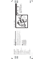
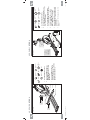
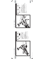
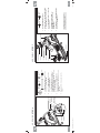
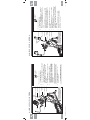
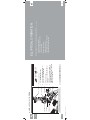
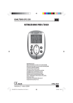
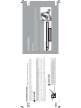
$(B$(B20B5HYBLQGG
6
3-POLE
GROUNDED
OUTLET
GROUNDING PIN
Never operate product with a damaged cord or plug even if it is working
properly. Never operate any product if it appears damaged, or has been
immersed in water. Contact Customer Tech Support for replacement or repair.
Connect this exercise product to a properly grounded outlet only.
WARNING
This product must be used on a dedicated circuit. To determine if you are on a dedicated circuit, shut off the power to that circuit
and observe if any other devices lose power. If so, move devices to a different circuit. Note: There are usually multiple outlets on one
circuit. This elliptical should be used with a minimum 15-amp circuit.
This product is for use on a nominal 110-120 Volt circuit and has a grounding plug that looks like the plug in the illustration. Make
sure that the product is connected to an outlet having the same configuration as the plug. No adapter should be used with this
product.
Improper connection of the equipment-grounding conductor can result in a risk of electric shock. Check with a qualified
electrician or serviceman if you are in doubt as to whether the product is properly grounded. Do not modify the plug provided
with the product. If it will not fit the outlet, have a proper outlet installed by a qualified electrician.
DANGER
This product must be grounded. If a elliptical should malfunction or breakdown, grounding provides a path of least resistance
for electrical current to reduce the risk of electrical shock. This product is equipped with a cord having an equipment-grounding
conductor and a grounding plug. The plug must be plugged into an appropriate outlet that is properly installed and grounded in
accordance with local codes and ordinances.
If your elliptical has power incline with a 3-prong plug, you must follow these grounding instructions.
GROUNDING INSTRUCTIONS
AFG
ELLIPTICAL
» Refer to the SERIAL NUMBER and MODEL NAME when calling for service.
MODEL NAME:
EP
SERIAL NUMBER:
ENTER YOUR SERIAL NUMBER AND MODEL NAME IN THE BOXES BELOW:
Before proceeding, find your elliptical’s serial number located on a white barcode sticker
on the front stabilizer tube and enter it in the space provided below.
SERIAL NUMBER LOCATION
There are several areas during the assembly process that special attention must be paid. It is very important to follow the assembly
instructions correctly and to make sure all parts are firmly tightened. If the assembly instructions are not followed correctly, the
elliptical could have frame parts that are not tightened and will seem loose and may cause irritating noises. To prevent damage to
the elliptical, the assembly instructions must be reviewed and corrective actions should be taken.
WARNING
ASSEMBLY
$0
7
TOP CAP
WATER BOTTLE HOLDER
PULSE GRIPS
REAR COVER
GUIDE RAIL SET
PIVOTING FOOT PADS
CRANK
CONSULTE A UN MÉDICO ANTES DE USAR CUALQUIER
EQUIPO DE ACONDICIONAMIENTO FÍSICO. EXISTE LA
POSIBILIDAD DE SUFRIR LESIONES GRAVES SI EL
EQUIPO SE USA INCORRECTAMENTE. LEER EL
MANUAL DEL PROPIETARIO ANTES DE USAR EL
EQUIPO. NO DEJE QUE LOS NIÑOS SE ACERQUEN A
ESTE EQUIPO. ESTE EQUIPO ES SÓLO PARA EL USO
DEL CONSUMIDOR.
ADVERTENCIA
CONSULTER UN MÉDECIN AVANT D’UTILISER
TOUT ÉQUIPEMENT D’EXERCICE. TOUTE
UTILISATION INCORRECTE PEUT OCCASIONNER
DE GRAVES BLESSURES. LIRE LE MANUEL DU
PROPRIÉTAIRE AVANT DE SE SERVIR DE
L’APPAREIL. TENIR LES ENFANTS À DISTANCE DE
L’APPAREIL. À L’USAGE DU CLIENT SEULEMENT.
AVERTISSEMENT
CONSULT A PHYSICIAN PRIOR TO USING ANY
EXERCISE EQUIPMENT. POSSIBILITY OF
SERIOUS INJURY IF EQUIPMENT IS USED
IMPROPERLY. READ INSTRUCTION MANUAL
BEFORE USING. KEEP CHILDREN OFF AND
AWAY FROM THIS EQUIPMENT. FOR
CONSUMER USE ONLY.
WARNING
UPPER HANDLEBAR
$(B$(B20B5HYBLQGG
8
3.1AE
CONSOLE
SPEAKERS
ATTENTION
GARDER LES MAINS ET LES
PIEDS LOIN DE CETTE REGION.
CAUTION
KEEP HANDS AND FEET
AWAY FROM THIS AREA.
MANTENGA LAS MANOS Y LOS
PIES LEJOS DE ESTA ÁREA.
PRECAUCIÓN
PEDAL ARM
LOWER LINK ARM
MAIN FRAME
STABILIZER TUBE
POWER SWITCH AND
POWER CORD SOCKET
LOWER HANDLEBAR
CONSOLE MAST
CONSOLE CONTROLS AND
DISPLAY WINDOWS
IPOD/MP3 PLAYER POCKET
USB PORT
TOP CAP
WATER BOTTLE HOLDER
PULSE GRIPS
REAR COVER
GUIDE RAIL SET
PIVOTING FOOT PADS
CRANK
CONSULTE A UN MÉDICO ANTES DE USAR CUALQUIER
EQUIPO DE ACONDICIONAMIENTO FÍSICO. EXISTE LA
POSIBILIDAD DE SUFRIR LESIONES GRAVES SI EL
EQUIPO SE USA INCORRECTAMENTE. LEER EL
MANUAL DEL PROPIETARIO ANTES DE USAR EL
EQUIPO. NO DEJE QUE LOS NIÑOS SE ACERQUEN A
ESTE EQUIPO. ESTE EQUIPO ES SÓLO PARA EL USO
DEL CONSUMIDOR.
ADVERTENCIA
CONSULTER UN MÉDECIN AVANT D’UTILISER
TOUT ÉQUIPEMENT D’EXERCICE. TOUTE
UTILISATION INCORRECTE PEUT OCCASIONNER
DE GRAVES BLESSURES. LIRE LE MANUEL DU
PROPRIÉTAIRE AVANT DE SE SERVIR DE
L’APPAREIL. TENIR LES ENFANTS À DISTANCE DE
L’APPAREIL. À L’USAGE DU CLIENT SEULEMENT.
AVERTISSEMENT
CONSULT A PHYSICIAN PRIOR TO USING ANY
EXERCISE EQUIPMENT. POSSIBILITY OF
SERIOUS INJURY IF EQUIPMENT IS USED
IMPROPERLY. READ INSTRUCTION MANUAL
BEFORE USING. KEEP CHILDREN OFF AND
AWAY FROM THIS EQUIPMENT. FOR
CONSUMER USE ONLY.
WARNING
UPPER HANDLEBAR
CONSOLE
SPEAKERS
AERO HAND GRIPS
INCLINE LEVEL TOGGLES
ATTENTION
GARDER LES MAINS ET LES
PIEDS LOIN DE CETTE REGION.
CAUTION
KEEP HANDS AND FEET
AWAY FROM THIS AREA.
MANTENGA LAS MANOS Y LOS
PIES LEJOS DE ESTA ÁREA.
PRECAUCIÓN
LOWER LINK ARM
PEDAL ARM
MAIN FRAME
STABILIZER TUBE
POWER SWITCH AND
POWER CORD SOCKET
LOWER HANDLEBAR
CONSOLE MAST
CONSOLE CONTROLS AND
DISPLAY WINDOWS
IPOD/MP3 PLAYER POCKET
USB PORT
RESISTANCE LEVEL TOGGLES
$0
9
4.1AE
F
F
F
F
F
F
F
F
F
F
F
F
F
F
F
F
F
F
F
F
F
1 Stabilizer Tube
1 Guide Rail Set
2 Pedal Arms
2 Lower Handlebars
2 Upper Handlebars
2 Lower Link Arms With Footpads
1 Top Cap (2 pieces)
1 Console Mast
1 Console Mast Boot
1 Console
2 Handlebar Caps
1 Water Bottle Holder
1 Rear Cover
1 Audio Adapter Cable
1 Power Cord
1 Hardware Kit
3.1AE only:
2 Handlebar Boots
4.1AE only:
2 Handlebar Covers
2 Aero Hand Grips
1 iPod® Dock Rubber Plug
1 Polar® Chest Strap
PARTS INCLUDED:
8 mm L-Wrench
5 mm L-Wrench
13/15 mm Flat Wrench
Screwdriver
5 mm L-wrench/Screwdriver
$(B$(B20B5HYBLQGG
10
ALL
MODELS
F
F
F
F
F
TOOLS INCLUDED:
If you have questions or if
there are any missing parts,
contact Customer Tech
Support. Contact information
is located on the back panel
of this manual.
NEED HELP?
NOTE: A light application of grease may aid in the installation of hardware. Any
grease, such as lithium bike grease is recommended.
NOTE: During each assembly step, ensure that ALL nuts and bolts are in place
and partially threaded in before completely tightening any ONE bolt.
Unpack the product where you will be using it. Place the elliptical carton on a level
flat surface. It is recommended that you place a protective covering on your floor.
Never open box when it is on its side.
UNPACKING
PRE ASSEMBLY
ASSEMBLY STEP 1
MAIN FRAME
BOLTS (A)
SPRING WASHERS (B)
ARC WASHERS (C)
STABILIZER TUBE
A
B
SPRING WASHER (B)
15 mm
Qty: 4
ARC WASHER (C)
17 mm
Qty: 4
Attach the STABILIZER TUBE to the MAIN
FRAME using 2 BOLTS (A), 2 SPRING
WASHERS (B) and 2 ARC WASHERS (C) on
each side.
Open HARDWARE FOR STEP 1.
BOLT (A)
30 mm
Qty: 4
HARDWARE FOR STEP 1 :
$0
11
ALL
MODELS
FLAT WASHERS (H)
$(B$(B20B5HYBLQGG
12
INCLINE BRACKET
FLAT WASHERS (D)
SPRING WASHERS (E)
BOLTS (F)
SPRING WASHERS (I)
NUTS (J)
4.1AE SHOWN
ASSEMBLY STEP 2
GUIDE RAIL SET
BOLTS (G)
MAIN FRAME
Open HARDWARE FOR STEP 2.
Attach the GUIDE RAIL SET to the
MAIN FRAME using 4 BOLTS (F), 4
SPRING WASHERS (E) and 4 FLAT
WASHERS (D).
Attach the GUIDE RAIL SET to the
INCLINE BRACKET using 4 BOLTS
(G), 4 FLAT WASHERS (H), 4 SPRING
WASHERS (I) and 4 NUTS (J).
C
NUT (J)
Qty: 4
FLAT
WASHER (H)
20 mm
Qty: 4
B
SPRING WASHER (I)
18 mm
Qty: 4
BOLT (G)
35 mm
Qty: 4
SPRING WASHER (E)
15 mm
Qty: 4
A
BOLT (F)
20 mm
Qty: 4
FLAT WASHER (D)
16 mm
Qty: 4
HARDWARE FOR STEP 2 :
NOTE: Be
careful not
to pinch any
wires while
attaching the
console mast.
4.1AE SHOWN
PEDAL ARM WHEEL
GUIDE RAIL
MAIN FRAME
CONSOLE CABLE
CONSOLE MAST
FLAT WASHERS (M)
BOLTS (L)
ASSEMBLY STEP 3
PEDAL ARM
CRANK
BOLT (O)
SPRING WASHER (B)
FLAT WASHER (K)
WAVY WASHER (N)
F
E
Repeat steps D–E on the opposite side of the
elliptical.
Attach the PEDAL ARM to the CRANK using 1
FLAT WASHER (K), 1 SPRING WASHER (B)
and 1 BOLT (O).
Slide WAVY WASHER (N) over CRANK
followed by PEDAL ARM as shown. Rest
PEDAL ARM WHEEL on GUIDE RAIL.
13
$0
Attach CONSOLE MAST to MAIN FRAME
using 4 FLAT WASHERS (M) and 4 BOLTS (L).
C
D
Open HARDWARE FOR STEP 3.
Carefully pull the CONSOLE CABLE through
the CONSOLE MAST using the twist tie located
inside the CONSOLE MAST.
FLAT WASHER (K)
20 mm
Qty: 2
WAVY WASHER (N)
22.5 mm
Qty: 2
A
SPRING WASHER (B)
15 mm
Qty: 2
FLAT WASHER (M)
23 mm
Qty: 4
HARDWARE FOR STEP 3 :
B
BOLT (O)
20 mm
Qty: 2
BOLT (L)
15 mm
Qty: 4
$(B$(B20B5HYBLQGG
14
PEDAL ARM BRACKET
FLAT WASHER (R)
SPRING WASHER (S)
BOLT (T)
4.1AE SHOWN
ASSEMBLY STEP 4
LOWER LINK ARM
FLAT WASHER (P)
WAVY WASHER (Q)
FLAT WASHER (P)
WAVY
WASHER (Q)
29 mm
Qty: 2
Attach the LOWER LINK ARM to the
PEDAL ARM BRACKET using 1 FLAT
WASHER (R), 1 SPRING WASHER (S)
and 1 BOLT (T).
Repeat steps B–D on the opposite side of
the elliptical.
D
E
Slide the LOWER LINK ARM into the
PEDAL ARM BRACKET.
Slide 1 FLAT WASHER (P), 1 WAVY
WASHER (Q) and another FLAT
WASHER (P) onto the LOWER LINK
ARM.
B
C
Open HARDWARE FOR STEP 4.
BOLT (T)
20 mm
Qty: 2
FLAT
WASHER (R)
20 mm
Qty: 2
A
SPRING WASHER (S)
15.4 mm
Qty: 2
FLAT
WASHER (P)
27 mm
Qty: 4
HARDWARE FOR STEP 4 :
4.1AE SHOWN
LOWER HANDLEBAR
RUBBER WASHER (U)
CONSOLE MAST
ASSEMBLY STEP 5
FLAT WASHERS (V)
SPRING
WASHER (B)
HANDLEBAR
CAP
BOLT (W)
FLAT WASHERS (H)
D
C
B
A
FLAT
WASHER (V)
25 mm
Qty: 4
BOLT (W)
20 mm
Qty: 2
FLAT
WASHER (H)
20 mm
Qty: 4
Repeat steps B–C on the opposite side of the
elliptical.
15
$0
Slide LOWER HANDLEBAR onto CONSOLE
MAST and attach using 1 FLAT WASHER (V), 1
FLAT WASHER (H), 1 HANDLEBAR CAP, 1 FLAT
WASHER (H), 1 SPRING WASHER (B) and 1 BOLT
(W).
Slide 1 RUBBER WASHER (U) and 1 FLAT
WASHER (V) onto the CONSOLE MAST.
Open HARDWARE FOR STEP 5.
SPRING WASHER (B)
15 mm
Qty: 2
RUBBER
WASHER (U)
26 mm
Qty: 2
HARDWARE FOR STEP 5 :
$(B$(B20B5HYBLQGG
16
TEFLON WASHERS (X)
LOWER LINK ARM
ASSEMBLY STEP 6
BOLT (Z)
SPRING WASHER (B)
FLAT WASHER (Y)
LOWER HANDLEBAR
NUT (AA)
4.1AE SHOWN
Align end of LOWER LINK ARM with bracket on
bottom of LOWER HANDLEBAR.
Place TEFLON WASHERS (X) on both sides of
the LOWER LINK ARM. While holding TEFLON
WASHERS (X) slide LOWER LINK ARM into bottom
end of LOWER HANDLEBAR.
Secure the joint with 1 FLAT WASHER (Y), 1
SPRING WASHER (B),1 BOLT (Z) and secure with
1 NUT (AA).
Repeat steps B–D on the opposite side of the
elliptical.
B
C
D
E
NUT (AA)
Qty: 2
Open HARDWARE FOR STEP 6. Remove zip tie
securing axle in LOWER LINK ARM.
BOLT (Z)
70 mm
Qty: 2
SPRING WASHER (B)
15 mm
Qty: 2
A
FLAT WASHER (Y)
17 mm
Qty: 2
HARDWARE FOR STEP 6 :
TEFLON
WASHER (X)
28.4 mm
Qty: 4
SCREWS (CC)
TOP CAP
REAR CAP
CONSOLE MAST BOOT
SCREWS (BB)
CONSOLE MAST
WATER BOTTLE HOLDER
REAR STABILIZER
ASSEMBLY STEP 7
TOP CAP REAR COVER
4.1AE SHOWN
E
NOTE: Be careful not to pinch any
wires while tightening screws.
Slide REAR CAP over REAR STABILIZER and
attach using 2 SCREWS (CC).
Slide WATER BOTTLE HOLDER over
CONSOLE MAST and attach using 2
SCREWS (BB).
Insert CONSOLE MAST BOOT over TOP CAP
and snap into place.
C
D
Open HARDWARE FOR STEP 7.
Slide TOP CAP and TOP CAP REAR COVER
over CONSOLE MAST and snap into place.
A
SCREW (CC)
15 mm
Qty: 2
B
SCREW (BB)
20 mm
Qty: 2
HARDWARE FOR STEP 7 :
$0
17
CONSOLE MAST
CONSOLE
$(B$(B20B5HYBLQGG
18
3.1AE
3.1AE SHOWN
NOTE: Be careful not to pinch
any wires while attaching the
console or handlebars.
LOWER HANDLEBAR
HANDLEBAR BOOT
PRE-INSTALLED
SET SCREWS
BOLTS (DD)
UPPER HANDLEBAR
CONSOLE CABLES
3.1AE ASSEMBLY STEP 8
Slide HANDLEBAR BOOTS over upper handlebars.
Slide UPPER HANDLEBARS onto LOWER
HANDLEBARS making sure handlebars are joined
together completely. Secure UPPER HANDLEBARS
to LOWER HANDLEBARS using PRE-ATTACHED
SET SCREWS.
D
E
F
Carefully tuck the CONSOLE CABLES into the
CONSOLE MAST before attaching the CONSOLE.
Attach CONSOLE to CONSOLE MAST using 4
BOLTS (DD).
3.1AE ASSEMBLY COMPLETE!
Slide HANDLEBAR BOOTS down to cover
handlebar attachments.
Make sure upper handlebars are as far down as possible.
Handlebars can be damaged If not secured correctly.
Attach the 3 CONSOLE CABLES to the CONSOLE.
C
Open HARDWARE FOR STEP 8.
B
A
* This step is for 3.1AE models only.
BOLT (DD)
12 mm
Qty: 4
HARDWARE FOR STEP 8 :
4.1AE SHOWN
LOWER HANDLEBAR
HANDLEBAR WIRES
PRE-INSTALLED
SET SCREWS
UPPER HANDLEBAR
BOLTS (DD)
AERO HAND GRIPS
NOTE: Be careful not to pinch
any wires while attaching the
aero hand grips or handlebars.
HANDLEBAR
WIRE
4.1AE ASSEMBLY STEP 8
Open HARDWARE FOR STEP 8.
H Repeat steps B – G on other side.
19
4.1AE
$0
Slide UPPER HANDLEBAR onto LOWER HANDLEBAR making
sure handlebars are joined together completely. Secure UPPER
HANDLEBAR to LOWER HANDLEBAR using PRE-INSTALLED
SET SCREWS.
F
G Connect the HANDLEBAR WIRE from the UPPER
HANDLEBAR to the wire from the CONSOLE MAST.
Guide the HANDLEBAR WIRE through the top of the LOWER
HANDLEBAR and through the slot.
E
D Attach AERO HAND GRIP to UPPER HANDLEBAR using 2
BOLTS (DD).
C Pull the HANDLEBAR WIRE from the bottom of the UPPER
HANDLEBAR while sliding the AERO HAND GRIP onto the
UPPER HANDLEBAR to prevent the HANDLEBAR WIRE from
becoming pinched and create slack to connect the wire.
B Carefully pull the HANDLEBAR WIRE from the AERO HAND
GRIP through the UPPER HANDLEBAR using the twist tie
located inside the UPPER HANDLEBAR and then discard the
twist tie.
A
* This step is for 4.1AE models only.
BOLT (DD)
15 mm
Qty: 4
HARDWARE FOR STEP 8 :
CONSOLE
WIRES
SCREWS (EE)
UPPER HANDLEBAR
CONSOLE CABLES
CONSOLE
NOTE: Be careful not to pinch any wires while attaching the
console or handlebar covers.
HANDLEBAR COVERS
CONSOLE MAST
BOLTS (FF)
$(B$(B20B5HYBLQGG
20
4.1AE
4.1AE ONLY
4.1AE ASSEMBLY STEP 9
E
D
4.1AE ASSEMBLY COMPLETE!
Carefully tuck the CONSOLE CABLES into
the CONSOLE MAST before attaching the
CONSOLE. Attach CONSOLE to CONSOLE
MAST using 4 BOLTS (FF).
Connect the 5 CONSOLE CABLES to the
CONSOLE.
Repeat on other side.
Attach right HANDLEBAR COVERS over
handlebars using 4 SCREWS (EE).
B
C
Open HARDWARE FOR STEP 9.
BOLT (FF)
12 mm
Qty: 4
A
* This step is for 4.1AE only.
SCREW (EE)
15 mm
Qty: 8
HARDWARE FOR STEP 9 :
• USING THE HEART RATE FUNCTION
• POWER/MANUAL INCLINE OPERATION
• LEVELING THE ELLIPTICAL
• MOVING THE ELLIPTICAL
• FOOT POSITIONING
• POWER/GROUNDING INSTRUCTIONS
• LOCATION OF THE ELLIPTICAL
This section explains how to use your elliptical’s console and programming.
The BASIC OPERATION section in the ELLIPTICAL GUIDE has instructions for the following:
ELLIPTICAL OPERATION
$0
21