1
MZ·IE02
SHARP
SERVICE MANUAL
CODE: 00 ZMZl EO 2 / /-E
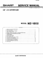
GP I/O INTERFASE
MODEL
~----------------------------
MZ-1 E02
CONTENTS ----------------------------~
1. WHAT IS A GP I/O INTER FACE? . . . . . . . . . . . . . . . . . . . . . . . . . . . . . . . . . . . . . . 1
2.
3.
4.
5.
6.
7.
8.
9.
10.
11.
12.
13.
14.
15.
SPECIFICATIONS . . . . . . . . . . . . . . . . . . . . . . . . . . . . . . . . . . . . . . . . . . . . . . . . . 1
DATA INPUT/OUTPUT FORMAT . . . . . . . . . . . . . . . . . . . . . . . . . . . . . . . . . . . . . . 1
INPUT/OUTPUT PINS . . . . . . . . . . . . . . . . . . . . . . . . . . . . . . . . . . . . . . . . . . . . . . 2
SIGNAL TIMING IN AUTOMATIC HANDSHAKING MODE ..... " . . . . . . . . . . . . . . 2
CONNECTION OF PERIPHERAL DEVICES . . . . . . . . . . . . . . , . . . . . . . . . . . . . . . . 3
PROGRAMMING . . . . . . . . . . . . . . . . . . . . . . . . . . . . . . . . . . . . . . . . . . . . . . . . . . 3
ERROR CODE TABLE . . . . . . . . . . . . . . . . . . . . . . . . . . . . . . . . . . . . . . . . . . . . . . 9
INPUT CODE TABLE . . . . . . . . . . . . . . . . . . . . . . . . . . . . . . . . . . . . . . . . . . . . . . . 9
MZ-1E02 CONTACT SIGNAL TABLE _ . . . . . . . . . . . . . . . . . . . . . . . . . . . . . . . . . . . 9
SETUP OF THE DIP SWITCH _ . . . . . . . . . . . . . . . . . . . . . . . . . . . . . . . . . . . . . . . . 10
MZ-1E02IGPI0) TEST PROCEDURE . . . . . . . . . . . . . . . . . . . . . . . . . . . . . . . . . . . . 10
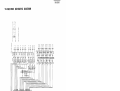
MZ-l E02 SCHEMATIC DIAGRAM . . . . . . . . . . . . . . . . . . . . . . . . . . . . . . . . . . . . . . 11
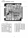
MZ-1E02 COMPONENT LOCATION . . . . . . . . . . . . . . . . . . . . . . . . . . . . . . . . . . . . . 12
PARTS LIST . . . . . . . . . . . . . . . . . . . . . . . . . . . . . . . . . . . . . . . . . . . . . . . . . . . . . 13
SHARP CORPORATION
MZ·IE02
1. WHAT IS A GP 110 INTERFACE?
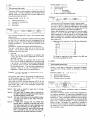
3. DATA INPUT/OUTPUT FORMAT
The General Purpose Input/Output Interface (GP liD) is designed for connecting general low-speed peripheral units (e.g.
The input/output format for data and control signals including
positive/negative logic, code length (8-bit/7-bit code), and
parity mode (even parity/odd parity/no parity) shOUld be set up
in accordance with the input/output format of the peripheral
unit to be connected. The method of setting the format will be
described in Part VII, Programming, p. 1 6.
measuring instruments, printers, X-V plotters, etc.) and providing information exchange between the main computer unit and
peripheral devices in a parallel 1/0 mode.
However, there are many different standards and features in
parallel interfaces, and they do not always provide satisfactory
information exchange for units having parallel interfaces.
It is reauested that the user fully understand this instruction
manual 'and sp8cifications of the peripheral units before using
this I/O interface.
Sharp cannot provide either hardware or software support for
special customer applications. Moreover, Sharp cannot in any
way be responsible for damages that arise as a result of customer misuse.
However, this instruction manual describes information necessary for exchanging information between the main computer
unit and peripheral units in so far as is possible.
1. B-BIT CODE AND 7·BIT CODE
8-bit code uses eight bits (eight pins) to express data and the
7-bit code uses seven bits (seven pins) to express data.
Either 8-bit or 7-bit code can be set for this I/O interface.
This interface unit has eight pins for each data input and
output, and setup of the 7-bit code permits the use of the
remaining bit (one pin) as a parity bit, as will be described
below.
2. PARITY CHECK
A parity bit can be added to 7-bit data so as to provide
a parity check of the data. An even parity check verifies
that the total number of 1 (logical "1") bits of data and the
parity bit is an even number, and an odd parity check
verifies that the total number of 1 bits is an odd number.
This I/O interface can be set to either an even parity check,
odd parity check or no parity check when the 7-bit code
is used.
2. SPECIFICATIONS
Model:
Input/output mode:
MZ-1E02
Parallel input/output mode (byte
serial)
1 channel
Number of channels:
12 pins (8 data input pins and 4 conInput ports:
trol signal input pins)
12 pins (8 data output pins and 4 conOutput ports:
trol signal output pins)
B-bit ASC II or 7-bit ASC II code
Data code:
Approximately 5 K bytes/sec. max.
Data rate:
Automatic handshaking or manual
Transmission mode:
mode
Even parity, odd parity, or no parity
Parity format:
bit
GMOOE, GSET, GIN, GOUT, and
Command words:
GBIT
Electronic components: Integrated circuits and discrete components
Operating temperature: 10 to 35'C
140 (W) x 142 (0) x 15 (H) mm
Outer dimensions:
160g
Weight:
Instruction manual (this manual),
Accessories:
F DOS Master
Note: One main computer unit can accomodate up to two
interface units (i.e. two channels).
The interface unit is mounted in slot 1, 2, 3 or 4 of MZlU02 Option Expansion Unit taht mounted in the
Model-3500 Series Business Computer Main Unit
(for two units combinations of slots 1 and 3 or slots 2
and 4 are not allowed). The channel number is determined by the slot number of the interface unit:
Slot 1 or 3 ................ Channel number: 0
Slot 2 or 4 ................ Channel number: 1
Two interface units may be mounted in any of four
combinations:
Combination
Slot 1
1
Channel 0
2
Channel 0
X
3
X
Channel 1
4
X
X
Slot 2
Slot 3
SIot4
Channel 1
X
X
... _--
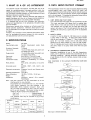
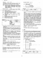
3. AUTOMATIC HANDSHAKING MODE
Automatic handshaking is one of the data transmission
modes, and it generally transfers data automatically in the
following procedures. Although automatic handshaking is
a basic feature of this I/O interface, manual mode can also
be selected.
Data transmission in the automatic handshaking mode (data
output).
Input control signals
,ACKNOWLEDGE, READY, etc.)0..!N",O,---!
reset?
YES
Data output
Set output control
signal {STROBE).
Input control signals
,--"N",O«ACKNDWLEDGE, READY, etc.)
set?
YES
Reset input control signals
(ACKNOWLEDGE,
More output ">2Y-"E"S_ __
data?
i
i
Channel 0
X
----1----- - - J
X
Channel 1
Channel 0
Channel 1
Data input is handled similarly.'
1
MZ-1E02
4. POSITIVE LOGIC AND NEGATIVE LOmC
This I/O interlace "can be set for positive logic or negative
"logic, independently f~r input data, output data, input can... ~r<?' ~ig!lal~, and output c9ntro] signals. The logical mode
,ot;QJltput,R()ntrol sigrais js set by,the DIP swjt~h on the
int~rfac~ PC bo~rd and the logical mode of other signais is
,~et l!sing a command_word (GSET commanc;lJ. For further
. details,' see Pllrt VU,. Prograrnmin~I'rp., 1-5 and Appendix 4~
Setup of the DIP switch; p. A-5.
4;' iNP "
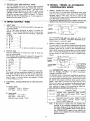
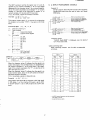
5. SIGNAL TIMING IN AUTOMATIC
HANDSHAKING MODE
1. SIGNAL TIMING FOR DATA INPUT
For data input in the automatic handshaking mode, signal
lines 11 to 18 are used 'for input data, 1.10 is used: f'or th~
~.TRO_~E signal in data input and 01_0. is -u~ed for the.
ACKNOWLEDGE signal which indiCates thatt'he interlace
unit (MZ-1 E02) has received data.
J~~.!~!!oyvin !1,I_u~t'~~~es t~~_t! J, 9 s.iQ.Qal.s _9_S~"rIJing that
PUTPrNS
signals' on liries 110 and 010 are in
Data signa!s
11 to 18
1. ' INpurPiNS'"
Th.is','jjo' j'nteriace ;has\(] 2 inpu"t pins, eight for data and four
for control .signals.
'th'e 12 iripu"t pins correspond to signals 11 through 112.
Signals 11 to 18 are data signals and 19 to 112 are control
signals.
These signals have the follQvying magnitudes
, (weighrs),:
.
1i l1i',' I!~ , ... :. . . .. 2°
,J,I~J10
2'
.3.13,111 ....... 2'
4: 14,112," ...... 2'
5., 15 ........... 24
~-+I\+,,---_:;_'-T"-4J\.,--~
at
T must be feast
78-.0.uS in dUration.
signal 110
ACKNOWLEDGE
signal 01 0
--~=-=:::f~-
95.0 ,uS to 170.0j,lS
The ACKNOWLEDGE signal on signal line 010 can be
replaced with the READY, REQUEST TO SEND (trans,
mission request) or the BUSY signal.
2. SIGNAL TIMING FOR DATA OUTPUT
For data output in the automatic handshaking mode, signal
lines 01 to 08 are used for output data, 09 is used for the
8. 18 ........... 27 or used as a parity bit or not used.
STROBE signal and 19 is used for the ACKNOWLEDGE
signal which indicates that the peripheral unit has received
data. The following Hlustrates the timing of signals, assuming that signals on lines 09 and 19 are in a negative logrc
system.
2. OUTPUT PI NS
This)/O iriterface has 12 output pins, eight for data and
fbL\r f~r'i:::0l1trol signals.
'The- 12_ ou'tput pins correspond to signals 01 through 012.
These signals have the following magnitudes (weights):
1. 01,09 ....... 2'
2. 02,010 ...... 2'
3. 03,011 ...... 2'
4. 04,012 ...... 2'
5. 05 .......... 24
Data signals
01 to 08
___~=t=+~~17~,O~"~S~'~5~%~,,______
STROBE
signal 09
If T1 is less than 3.5
Tl + T2 must be
at least 3.5 .uS; if T1
is equal to or more
than 3.5 .uS, T2 must
be at least 78.0 p.S.
tLS,
ACKNOWLEDGE
signal 19
6. 06 .......... 2'
7. 07 .......... 2'
8. 08 .......... 27 or used as a parity bit or not used.
After power has been switched on, signals 01 to 08 are ON
The ACKNOWLEDGE signal on line 19 can be replaced
with the READY, REQUEST TO SEND (transmission
request) or the BUSY signal.
As described above in aautomatic handshaking, signal lines
11 to 18 are used for data input and 110 and 010 are used
for control signals during data input. Signal lines 01 'to 08
are used for data output and 09 and 19 are used for control
signals. Input lines 111 and 112 and output lines 011 and
012 are not used in the automatic handshaking mode and
these lines can be used arbitrarily. The following shows
some examples of signals to be transmitted on these four
lines. Also refer to the GBIT command, p.30.
(high level) and signals 09 to 012 may be ON (high level)
or OFF (Iow level) as set by the DIP switch on the interface PC board. For further details, see Appendix 4, Setup
of the DIP switch, p. A-5.
ELECTRICAL CHARACTERISTICS OF INPUT/OUTPUT
PINS
1) Output signals
ON (high) : > 2.4 V
OFF (Iow) : <0.5 V
---y-------,r---
STROBE
6. 16 ........... 2'
7. i7 ........... 2'
3.
a positive logic s'istem~
0.25 mA
48 mA
Signal line
2) Input signals
ON (high) : 2.0 - 5.25 V
OFF (Iow) : -0.5 - 0.5 V
Maximum input voltage: 5.25 V
11T,''i'l2'
ERROR Signal, WARNING si'grial, PAPER
END signal, ALARM signal, FAU LT signal,
WAIT signal, etc.
011, 012
MACHINE SELECT Signal, REMOTE POW,
ER-ON signal, INITIAL. RESET signal,
FAULT RESET signal, etc.
Note:
2
ExamplE!,of signal
If data input or output does not operate satisfactorily in the automatic handshaking mode and
the system hangs up in the wait stat~ (e.g., the system waits for the STROBE signal in data input or
the ACKNOWLEDGE signal in data output), the
system can be released from this state by pressing
the HALT button.
MZ-IE02
6. CONNECTION OF PERIPHERAL
DEVICES
1. PERIPHERAL DEVICES THAT CAN BE CONNECTED.
General low-speed peripheral devices (e.g., measuring instruments, printers, X-V plotters, etc.) having parallel interfaces can be connected. The Model-3500 Series Business
Computer Main Unit can also be connected to another
computer having a parallel interface.
Processing of control signals and operation (timing) of the
automatic handshaking modes differ for each device and the
specifications of each device must be satisfied. For further
details, see the following paragraph.
2. PRECAUTIONS FOR CONNECTION
The user should first carefully check the specifiecations of
each peripheral device before connection is made.
This paragraph describes general precautions.
1) Electrical characteristics of the input/output pins
Confirm that the peripheral device to be connected
satisfies the characteristics shown in Part IV, 3, Electrical characteristics of input/output pins, p. O.
In particular, make sure to check that the output voltage of the peripheral device does not exceed the maximum input voltage of the MZ-1 E02 interface. Excessive
signal voltage can cause damage to the interface unit.
2) Automatic handshaking mode
Confirm that data is transmitted to the peripheral device
in accordance with the flow chart for data transmission,
as described in Part Ill, 3, Automatic handshaking
mode, p. 8. The timing of the signal on line 010 at
data input and the signal on line 09 at data output must
satisfy the specifications of the peripheral device.
The setup time for the signal on line 110 at data input
and the signal on line 19 at data output must be long
enough, as specified, to ach ieve satisfactory data transmission.
3) Manual mode
If data transmission does not operate satisfactorily in
the automatic handshaking mode, carry out data transmission in the manual mode where control signals are
input and output by the program (GB IT command).
Data transmission in the manual mode takes 10 seconds
or more, and the timing of each control signal must be
considered carefully.
4) Other
When a printer is connected as a peripheral device, set
the eR code of the printer to the carriage return (without line feed) function, i.e., turn off the automatic
line feed. A CR code and an LF code are output automatically following data output.
Slot number
1
2
3
4
Channel
0
1
0
1
number
2) Wiring
Solder the each loose wire of optional GP I/O interface
cable [MZ-1C19] with a proper connector of peripheral
device according to Appendix 3. MZ-1 E02 Contact
signal table. Connect all GND lines (24 wires) of the
cable to the GNO pins of the peripheral device.
Extension of the cable must be within 2 meters and
sufficient precautions must be taken for noise protection to ensure reliability.
3) Attaching the connector
Connect the interface MZ-' E02 and the peripheral
device with the cable [MZ·l C19].
And then fasten it with two screws on the both end
sides of the connector.
4) Power·ON
Set the GP I/O interface controlling FOOS Master disk
(accessories) in the Mini-Floppy Disk Drive unit
(channel-drive number AO) that located on the right
hand side of the Model-3500 Series Business Computer
Main Unit.
Turn power on the peripheral device (CRT display,
etc.), then the Model-3500 Series Business Computer
Main Unit.
(The FDOS Master attached with Model-3500 Series
Business Computer Main Unit and that of version No.
V2.0 are not applicable.)
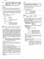
7. PROGRAMMING
For ease of understanding of the syntax and rules of command
words, the syntax notation is defined as follows. This notation is effective only in describing the syntax and rules, and
should not be used in actual programs.
Symbol
Meaning
I
[
J
I
I
(
)
"
S, T
A
AS
3. CONNECTING PROCEDURE
N
Note) Switch off the power supplies to the Model-3500
Series Business Computer Main Unit and peripheral
devices before making connection.
X, Y, Z
C, D, E
---
1) I nstalling the MZ·1 E02
Install the MZ-1 E02 in one of slots 1, 2, 3 or 4 of MZ1 U02 Expansion Unit that mounted in the Model-3500
Series Business Computer Main Unit. After installation,
secure the MZ-1 E02 with screws that closed the slot
cover.
The interface unit is assigned channel 0 when it is
mounted in slot 1 or 3, or the unit is assigned channel
2 when it is mounted in slot 2 or 4. (See the following
table.)
3
Indicates the separation for selection.
The part enclosed in brackets [ ] can be
omitted. When this is omitted, the funcI tion is merely invalidated or a different
function is validated.
. The part enclosed in braches { ) can be
written repeatedly using a comma ( , ).
The aprt enclosed in angles ( ) can be
written repeatedly using a semicolon ( ;).
Indicates an iteger,
(Example: 10)
Indicates a character constant.
(Example: "NAME")
Indicates a numeric variable (including a
numeric array variable),
(Example: NO)
Indicates a S- or @-type character variable
(including character array variable).
(Example: DAS)
Indicates a variable (numeric or character
variable) (including an array variable).
Indicates a numeric expression.
Indicates a character string.
Indicates a flow of syntax.
~
Indicates selection.
...c'l.
Indicates repetition.
~
Indicates omission.
MZ-lE02
In actual operatio'n, -I ENTER I key must be pressed
at the enci.---or-~ach- _pro-gram step. (For' m~ltiple
statement :.en_try, statements must' be separated
Note 1)
2. GSET
This command specifies the logical polarity of Input/
_ output ~ata signals and input control signals.
using a colon ( : ).}
Note 2)
th~
,Enter the program with
MZ-1E02 installed.
This command is effective only-for channels and ports in
the automatic handsha"king mode.
1. GMODE'
Fqrmat) GS~T
Thi~! com~and ,~ets
up the inp~t/output channel modes. .
.
',:,
, ' ,
'
Channel number (0, 1)
X
-------'-~----'---"'-'~~~~=~~---"-~~-~~------'e
'i'ypi;-"fsig,",ls"'-~----'~=--~~----'~--
Th~ set'~p' ~~de~ include the automatic :nandshaking mo'de
or manual mode for input/output ports, S-bit or 7-bit cOde
for the automatic handshaking, ~ode, and 'tne- parity check
mo'de.
ID ........ Input data signals
OD .. . . . .. Output data signals
le ........ Input contr'ol'signaj~
Positive logic/Negative logic
0:
F?rmat) GMODE
C,
(X,)
0 (,El
[x.) C, D
I (SYNTAX)
X: Channel number (0, 1)
C : Port
L-_rr<ID-r-0-rl________
1'1' ,L ... ;; .... Inp~t port
.. 0 ........... Output port
D ; !Mode'
E
A ..... ',._ .. AutOinatic handshaking mode
B ........ Manual mode
Data format
This command specifies the logical polarity of signals on
a channel, as indicated respectively by the character strings
D and C, ahd the expression X.
The logical polar~ty of signals can be specified in two ways:
S ......... S-bit code
i)
7E ....... 7-bit code with even parity bit
70 ....... 7·bit code with odd parity bit
7 ......... 7-bit code without parity bit
Specifi,cation for a group of signals (8 data bits or 4
bits) as designate~ by string C:
Character string D: Positive logic ........... "1"
Negative logic ........... "0"
ii) Specification of individual signals as designated by
character string C:
Character string D:
Example for input control signals:
"0101"
1]1'.
Numeric expressjon X selects the channel with character
~tring C selecting which port and character string D .selecting
the mode (automatic handshakin9.' mode/manual mode).
When the automatic handshaking mode is specified by D,
data format can be specified by the character string E.
If (X,] is omitted, channel 0 is set automatically. If E is
omitted in the specification of the automatic handshaking
mode, 8-bit data code is set automatically. After power has
been switched on, the input and output ports of each channel are set to the automatic handshaking mode with 8-bit
data code.
If
Addendum)
10 GMOOE "O","A",'"7E"
This program specifies the automatic handshaking mode for
7-bit code with even paritY' check for the output port of
channel O.
,," .".",--"
., ..
:..
._ ... __ ~ __ ;
The 7·bit ASCII cdde system has the SIISO state for handling as much data as .an
8~bit
The logical polarity of the output control
signals is set by the DIP switch on the
interface PC board. (This command cannot be used for that purpose.) For details, see Appendix 4, Setup of the DIP
switch, p. A-5.
,
Addendum) SIISO (shift-in/shift·out)
•• '
10 GSET "00", "0"
This program specifies negative logic for all output data
signals (8 bits) on channel O.
/ SO (shift-in/shift-out) state is automatically set
to SI by execution of this command.
;_,J~
is omitted, the logical polarity for channel 0
Example)
~l
--"~;
Negative logic for signal 110
Positive logic for signal 111
Negative logic for signal 112
is set.
After power has been switched on, positive logic is set
for all input/output data signals and input control
signals for each channel.
Note) For data 1/0 in the 7-bit ASCII code system, the
Example)
ex,)
Positive logic for signal 19
code system does.
The SO code (CH R$ &OE) switches the SI state to the SO
state, and the SI cdde (CH R$ &OF) switches the SO state
to the SI state. Accordingly, data iri the 7-bit ASCII code
system includes SI codes and SO codes. These codes must
be taken into considerati'on in programming when the
amount of data is significant. The SI and SO states are
independent for the input and output ports and for each
channel.
After power has been switches on, the SI state is automatically set.
4
MZ-lE02
Format 2) GIN
3. GIN
This command enters data.
manual mode input command.
I
I
X, N, CC, DJ
-
D
-
.
-
GIN-.-~ch".r.c'.r
~
l...cD-J-=-~~
(SYNTAX)
f,\
_
I
Channel number (0, 1)
Variable for inputting data
End code 1
End code 2
X
N
C
11
E : Type of signals
D ........ Data signals
C ........ Control signals
A: Numeric variable for inputting data
The syntax differs in the automatic handshaking mode and
manual mode. Format 1 applies to the automatic handshaking mode input command, and Format 2 applies to the
Format1)GIN
X, E, A
Channel number (0,
X
1
_
_
_
-,
I
.~
Format2 of the GIN command is used in manual mode.
The GIN command inputs the logical level (ON or high,
and OFF or low) of a signal as designated by the character
string E to the numeric variable A as binary data for the
channel as designated by the numeric expression X.
Binary data produced by this command will have the magnitude of 1,2,4,8, 16, 32, 64 or 128, or any sum of these
values depending on the bit position in the ON state (high
level), irrespective of the logical polarity specified by the
GSET command. Bit positions in the OFF state (Iow level)
give a value of O.
This command (Format 1) is used in the automatic handshaking mode.
The GIN command inputs data to variable N unitl end codes
are read (will be described shortly) as designated by the
character strings C and D for a channel as designated by the
o
Magnitude of bit positions in the ON state (high level):
11,19..................
1
12,110 ................. 2
13,111 .................
4
14,112 .................. 8
15 ...................... 16
16 '" ................... 32
17 ...................... 64
18 ...................... 128
numeric expression X. The end codes are not input to the
variable N.
If the area for variable N overflows, ERR 0 R 205 occurs.
The NULL code has no effect and is not input to the
variable. For character strings C and D, only the first
character is valid as an end code.
o
End code
When one end code is specified (,D is omitted), data
is input until the end code as designated by the character string C is met.
Whe two end codes are specified, data is input until
one of the end codes as designated by character strings
Cor D is met. In this case, if the end code as designated
by character string C is met, the succeeding statement
will be executed next. If the end code as designated by
character string D is met, the statement in the
subsequent program step will be executed next.
Example)
10 GIN O,A$,CHR$ &7F ,CHR$ 8.00:GO TO
The range of magnitude of data signals is 0 to 255, and
that of control signals is 0 to 15.
4. GOUT
This command output data.
Syntax 1 and 2 apply"to operation in automatic handshaking mode, and Format 3 applies to operation in manual
mode.
10
Format 1) GOUT
20 DISP "A$=";A$
This program inputs data to the character variable A$ until
the DEL (delete) code (Le. CHR$ & 7F) or CR (carriage
return) code (Le. CHR$ & OD) is met.
Upon input of the DEL code the statement 'GO TO 10' will
be executed next, or upon input of the CR code, the statement 'DISP "A$=" ;A$' in the subseqQent program step
will be executed next.
Note 2)
Note 3)
Note 4)
Null code is invalid to input even in @-type
character variables.
For input data in negative logic as specified by
the GSET command, complementary data (having
an inverted polarity) will be input.
The data of 253 bytes or less is available to input
at a tirm, more bytes of data input invite error
(y
C
X
Channel number (0, 1)
Y
C
Numeric data to be output
Character data to be output
>
C; )
1 (SYNTAX)
,
GOUT ,-dD-.,c,-~
' - . 1_
Note 1 J
X,
_
_
_
Format 1 of the GOUT command is used in automatic
handshaking mode.
The GOUT command outputs numeric data designated by
the numeric expression, or literal data designated by the
character string C to a channel designated by the numeric
expression X. With a semicolon attached at the end of the
last numeric expression or literal string, no CR code (CHR$
(ERROR 125).
If CHR$ &01 through &1F and CHR$ &81
&OD) nor LF code (CHR$ &OA) is output following the
output of data. Conversely, if a semicolon is omitted at
the end of the last numeric expression or literal string, a
CR code and an LF code are output automatically follow·
ing the output of data.
through &9F is specified as the end code in the
7-bit code system, the end code is detected using
7·bit data irrespective of the SI/SO state. If
CHR$ &20 through &7F and CHR$ &AO through
&F F is specified as the end code, the end code
is detected using the SI/SO state and 7-bit data.
5
MZ·IE02
Example)
10 GOUT 0, "ABC" :\
Format3) GOUT
This program outputs literal s1:i-iri~j' (lifer'aT constanW" ASC"
data followed by a CR code and LF code forchanriel O.
Note)
For output data in .rieQCitive logic as specified by the
GSET comman~.~:· ·'~oinpl~~entarY. :d~tCl.: (having
inverted poia'rity) will be outP~l"t.· (This r'ule also
applies to Format 2.)
Format2)·G.OUT "
x·.,
USING
ri'l· S I'(Y) I A$ I IMAGE
X.,h"Gha~reL"~mb~\(q,J).
':'-'f;i.; .,;, L,if)~ mJwb~rva~ye_.of IMAGE st~~ern,en~ ;-~
~-,;~.;.~ '," :') Lj~e !a.bel.-~~ITI~ eJ ,lMA~.E 5~,a~e.m~t1t .
,);'";( J.: ,L,in e , ,~1:ll}lb~;r ,(numer,ic expressio~) of IMAGE
_~at,eITIIi!n1; ; "ji _.
..,'
.
: .~A$,,: , Character ,- 'variable_ - for. -specified. format (!~~_ge
Cl;
r'_: ,~Y_!l1b'pl); ',", ;:. , -~- - -', -~ -: -~ :- - ---, ~ --- ----T· .:". Character cQnstan~ indicating im.age symbol
J
~J" ~~meri'c.~at~;,~~ ~~ 9utPU.~' , -
~
!:i':'~i: ::;;Gh~.~~~tf1r dat~:.~,?.b.elp.lJ~'pyt
-j -
.
Channel number (0, 1)
Type of signals
o ...' .. ~ .. Data signals
C". '.':...:'... Control signals
NUmeric. data ·to be OUtput
:, A}:
I(SYNTAX)
C{Z I CLC-:.-J-JJ-____~--I
.- - - T
Z :
X
E
X, E, Y
I
. .
.-
I
-
GOUT~
.Ch.n~ • . . '."m.o,.;." . . . . .
~-'----r'
_
I
_
•
',---.'~.
---l.
- , ,.. ,,'
.J
Format 3 of the GOUT command is used in :tpe m~nua!
mode.
The GOUT comm~nd Qutputs numeric data designated by
the numeric expression Y in binary format with' the logical
-polaritY-oaf "the signafs-'designated_b-v the--charactei' string ~
to a channel designated by the numeric expression ~.
this command outputs an ON state. (high level) for. a-O
bit; irrespective of the' iogiccH "Polaiity' ~pecified by the
GSET command. The logical polarity of output 'cbntrol
sig'nals' is determined by the DI P switch o.n the inierf~de PC
, board {See·p. A-5 0 } 'Wh'en'the character string E iS'set to
data . signals, tile' niagn'itude of the riu"n1eric expreSsion Y
must b~ within' the' ra~ge from 0 to 1.5 If this range is
exceeded, ERROR 127 occurs.
NoCR cdde (CHR$&OD) ;,or LF code (CHR$ &OA) is
output a't th~ 'end bf the 'output data.
'--.c'
_
_
Note} Use this command for data. in. the a-bit code system.
Format 2 'of the GOUT command is used in the automatic
hJ~"d~ha.king.. .
,
'. Th"Et GOUT command outputs,;numeric data designated by
the numeric expression Z 'or literal data designated by the
character string C in a format designated by the IMAGE
statement.
This syntax conforms to Function 2 of the PR INT state·
ment.described in the MZ-3500 BASIC LANGUAGE
.. MA,NY/',!I,'.rc<"lso !~'er. t? the IMAGE .statement.
It a s.~micolon is attached .to the end of the last numeric
~xpr~ssiori'or 'Iiter~I' string, no CR code (CHR$ &00) nor
LF code (CHR$ &OA) is output following the,output of
data.
Conversely, if a semicolon is omitted, an LF code is output
automatically at end of the. dat;;! (,No CR code is output).
If {Z I C f e;) is omitted, neither CR code nor LF
code is output.
The eR code and LF code C(in be set using the IMAGE
statement.
Example 1) 10 GOUT 1,USING 500,X$,Y$
ThJs pr.Qgr~1l] outputs character"strings X$.. and Y$ in the
format
specified by the IMI:\G.E :..sta,t~!11~nt
.for channel
1.
. : :. ;. i: : , . ::, :;, ~ : .. ; j': .• , i :,: , . ,'; . )
.
,; j ;
.
,
Example 2)
10 H$="TRANSISTORS":K=1320
':,.' i:.~~g,.:~~~T;i-O~·~~~NP) lPR!.~.~~~~!
. °ioo: IMA·GE.,,~'llA 5X":·,"PRI.CE'"
"') ,...
,:,1
.
;:
',')
,.
;;;.
.
.
"TR''';;'N<sr STOR s'Sp
'.1
'.
""
.,
',,'
.'"
I
SpSpSpSp$ 1 , 3 2 0 CRLF
SpSp Sp Sp
PR
IC E
The NULL code can be output.
10 GOUT 0, "0",0%
This program outputs a NULL code for channel. O.
5. GBIT
This command verifies and sets the logical level· of signals.
This command is effective for ports in both automatic
handshaking and manual ·modes. .The. commahd has no
relation to the logical polarity specified by the GSET
command. The logical polarity of the· output control
signals is determined by the DIP switch on the interface PC
~oard. See. Appendix 4, Setup of the DIP switch, .p. A-;.
Formatr) GBIT . eX,
) c, Y, A
X
Channel number (0, 1)
C : Txpe ofsi9n81s
.
ID ........ Input dClta s.ignals
le ........ Input contro'l signals
Y
Pin number
0 ......... 1),19
1 ......... 12, 110
2 ; .. : ';i . " . .13, III
3.. ....... '1(112
4 ......... 15
4X $#.,### C·
j,: .
•
Example)
,'1!" I.'; ,).i,
. 'Th!~' p~9~r~~ 9':u1r,~:s., c,la~~ .i:n. the .follo~ing .format, ~lJY~ere
Sp,CR, and LF signify a space code, CR code and LF code,
respectively..
. . . . . . .. .-.
.
! '.'
Addendum)
5 ......... : 16
6 ......... 17
7 ......... 18
,f!\:
.~umeril? variabl~.~9r
inputting data
MZ·lE02
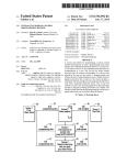
6. A SIMPLE PROGRAMMING EXAMPLE
The GBIT command verifies the logical level of a pin designated by the numeric expression Y for an input signal
designated by the character string C for a channel designated by the numeric expression X, and assigns "1" to numeric
variable A if the state is ON (high level) or assigns "0" to
numeric variable A if the state is OFF (Iow level).
If (X, J is omitted, a signal on channel 0 is verified.
Example)
Sample program describing data transfer with automatic
handshaking mode using two sets of main unit Model
3500 series.
10 GBIT "IC",2.A
20 IF A=l THEN "ERR"
10 GMOOE u, "0", "Pt", "8 ' ................ Sets the mode (Output port).
20 A$:='· SHARP
J 30
L
level).
X
[X, 1 C, Y, Z
Channel number (0,
GOUT O,A$I ............
·······Output character date "SHARP".
GOUT 0, CHR$ &FF; .
···············Output ending code "CHR$ &FF".
GMOOE 0," 1··, "A", "8"·
. ······Sets the mode (Input port).
"'() r, 1NO. B$. CHR$ &FF ............•.•.•. 'Input character data.
\40
50
This program checks signal 111 on channel 0, and branches
the program to line iabel "ERR" if the signal is ON (high
Forma(2) GBIT
11
Example
11
C : Type of signals
OD ....... Output data signals
OC ....... Output control signals
Y
Pin number
0 ......... 01,09
1 ......... 02,010
2 ......... 03, 011
3 ......... 04,012
4 ......... 05
5 ......... 06
6 ......... 07
7 ......... 08
Z
Set of signals
~g ~~6P
A$;8$
10 (i,IOOE 0,"1··,",,"","8"···
. ···Setsthe mode (Jnputport).
2u GIN U,A$,(.Hf($ 8.FF····
········lnput character data.
38 GMOOE 0, "0", "A··, "8 '·················Sets the mode (Output portl.
40 i3$",··tlode 1-350L)··
j50 GOUT 0,13$1 .....•...•
160 GOUT 0, (;Hf($
&FF 1"
··············Output character data "Modal-3500".
···················Output ending code "CHR$ &FF".
70 01SI-' A$;8$
80 END
Execution results
"SHARP Model-3500" is displayed onto the both of
CRT A side and B side.
Cable connecting table
When executing program, use the cable corresponded
as follows.
0 ......... OFF (Iow level)
1 ......... ON (high level)
Side A
Signal
name
When the character string C indicates that the signal is an
output data signal, this command sets a pin designated by
the numeric expression Y to ON (high level) if the magnitude of the numeric expression Z is "1", or sets the pin to
When the character string C indicates that the signal is an
output control signal, setup of the DIP switch on the interface board functions inversely.
If (X,) is omitted, a signal on channel 0 is set.
Example)
No.
No.
1
25
11
3
5
27
12
29
13
04
05
06
7
31
9
33
OlD
I
J.
:
:
..
level).
35
37
17
_~
39
18
19 __
41
43
1
110
01
_-'-'-- ><
11
2~ __
?~_
---
31
15
~3
16
35
17
37
_.~8
39
19
41
110
43
--.~
__
~--
-
-
_.9
05
06
11
...
~
...><--.
19
02
03
04
17
07
08
09
19
010
13
-
16
3
5
7
15
o All GND (ground) contacts must be connected
with those of partner.
o Unused contacts are open.
7
14
15
11
12
__ 14
,
13
~-----,--?9_ _
This program sets signal 09 on channel 0 to ON (high level)
if DIP switch 1 on the interface PC board is set to OFF.
If the DIP switch 1 is set to ON, the pin is set to OFF (Iow
Signal
name
02
03
_08
09
10 GBIT "OC",O,l
Contact
01
07
OFF (Iow level) if Z is "0".
Side 8
Contact
~xample
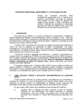
Example 2 ) "
3)
SampJI:! pr.ogram de~c;ribing. cfClt~_ transfer, with .00Cinual
mode· l,Isjng.·a_. mail"") ljnit _MpQe_I-3500 seri.es and' printer
[MZ'1 P02]"
Sample program describing data transfer with manual
mode using two sets of main unit Model~350n ~eries.
10 G81T-'o:;;aC",,3-.-0-:;.;, ... ;. _____ ..-_~._ Output controf_~ig;'-al"~12 OFF.
~g '~~~~i),:;~~i:-;:~
,-
GMOOE 0, "0". "8" ....... -----.---.----- Sets the .mQge ,(OjjtP~t portJ.
GOUT O. "O".A .-.~---- ••.•• -._------ ____ Output numeric data A.
G8IT 0, "OC", 3.1 .---.---- ..••• -------- Output control signal 012 ON.
la Gt:loDE' 9:,"~:> "8' ',",''''''''''- ---,---",Sets themdde- (Ou-tpuipon).
G8lT 0." le" .2. x ........ ---- ..... ----- Verify input control signal 111.
?O ~I3IT O. "Ot;" ,I, 1. __ .. __ .... __ . _____ ...... Output control signal 010 ON.
IF x-a THEN 70
3,° B""ATO 0A' DC ,O,t. _____ .. ____ ~
" ONPU r;PR1ME s.."nal·, "
; j' 'i6 :G06"t'-:·6;·;··b;";iV-:--·~-~;---.-- .. -----.----- Outilut numeric da'i:~ B.
500 IF .'1=0 THEN END
·----·---··.Output control srgnal 09 ON.
100 G8IT. O. "DC" ,~,O j-.; •••••. ---n--n----Output control signal 012 OFF.
60 GOUT 0, "IJ" ,A " __ n.n_.n._.,
{DATA SI RO~e signal at printer}.
1-10 GBH 0, '.'IC." ,2, X ., .. -------.•. --.----- Verify inp~t control signal 111.
70 GBIT 0 "~C" 0
···--------··Output numenc data.
IZ,j If7.·X=I·THEN 110
' _ _ _ _ _ _--"~-'
,.,.
n'"
,""I'Q"
1-3e.:-G-1'18eE-:-e'..,.....r! '8 1
Se~the-mod.e-{·I:np,!:.it'-portr.
80--Gs:J:.~Q-,-!!0'Gll-rs-i+ nnn.-----.. --- •. -'.'crrtput.coh.t~o -sigRa":' 9-QFF;-e~
140 GIN' 0" ;"0"'; t '.. ,.. ~'-': -----.. -----...... Input numerrc data.
90 GBIT _0, "I.Co";O, 8 '--·--·-··--···----:--~:-·Verif.y ,input contrpl'signal' 19;
150 OlSP A:"+":8:"=":C
i~g ~6 ~DI4~HEN 90
IBUSYsignal at printer):._
40
50
60
70
80
"i";"".
01
o·
160 END
.
.2QO OATA:·i":,83.72,Q5.82,8Ij.10
210 [lATA :31:,83, 72, 05.82.80,10
220 DATA :30:,83, 72 .65,82~80, 10
~~g g~~~ i~I'~h:;::;~~;~~~~:::'1.0
,: "i
fa GBH' '0 ,':'QC" .2;0 .-.- ..•. ---------------- Output control singal 011 OFF.
20" GEtl TO., "le:' • .3, x •••_--------•• ---------- Verify inpUt contml signal 112•
.. J'--30_ IF ')::1' -THEN' 20 1' '
, 4d ~MODE '-d', "1", '~B" -.. -------------------- Sets the mode (Input port).
so GBI T 0," LC" ,3, X ----- __ ••••• ___________ Verify input control signal 112
60 IF X=O THEN 50
70 GIN 0, "0" ,A ---------- ______________ .•.. Input numeric data,
80 G81T 0, "OC" ,2 ,1 ---------------- ...... Output control signal 011 ON.
90 G81T O,"IC",3,X ----·····-------------Verify input control signal 112.
.
100 IF )(=1 THEN 90
1,10
'120
130
14';"
ISO
160
170
LF ,code
Function code designating character
pitch and double width.
GIN 0, :'.0" .8_.--------~,_--------- •••.•• _._ Inp!JJ numeric-data.
'01'31" '''A=''':A:OISf'_ "B=":S
,--,
C=A+8
('-MO[lE
C)!
Execution results
Executing this program gets the following kinds of
character on printer.
"0", "S" ------ ---------- •• ---- Sets the mode '{Output portl.
GOUT 0, "0". C -------('-S11 0,"OC",2,(1
---------··Output numeric data C.
----·--------Outputcontrolsignal 011 OFF.
ENO
SHARP ·----------------··---Character pitch to 16.5CPI.
SHARP --------··-----Character pitch to l6.5CPI, double width mode.
SHARP ----------···----Character pitch to 10CP!.
S H A R P -'---Character pitch to 10CPI, double width mode.
Execution results
Result is displayed at A side after calculating at B side
the total of two numeric datas which is input through
Aside.
Cable connecting table
When executing program, use the cable corresponded
as follows.
Side A
Signal
name
Contact
01
02
03
1
3
5
7
0'
05
06
07
08
012
11
No.
Cable connecting table
When executing program, use the cable corresponded
as follows.
Side B
Contact
Signal
No.
Name
~ain
Signal
name
11
25
unit side
Contact
N,.
Printer side
Contact
No.
,
Signal
name
27
12
01
1
29
13
02
3
,
31
33
14
5
15
03
04
.3
4
7
5
DATA B.IT4
11
35
16
05
13
9
6
DATA BIT5
37
17
15
39
'8
112
01
02
03
0'
05
06
07
0' .
011
23
47
25
1
"
27
13
29
14
15
31
33
3
5
7
,
16
35
17
37
11
13
IS
39
15
111
45
21
.
11
7
DATA BIT6
07
13
B
DATA Bin
b'B
15
9,
DATA B1TB
0"
010
17
1
DATA STROBE
19
41
31
INPUT_PRIME
11
BUSY
43
10
~
LEDGE
45
47
12
PAPER END
13
SELECT
111
112
o All GND (ground) contacts must be connected
with those of partner,
o Unused contacts are open,
8
DATA EHT3
06
'9
110
o All GND (ground) contacts must be connected
with those of partner.
o Unused contacts are open.
DA1'.A BIT1.
DATA BIT2
MZ-lE02
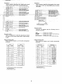
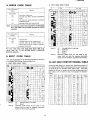
2. 7·BIT ASCII CODE TABLE
8. ERROR CODE TABLE
Error code number
Meaning
lE R NI
(odd number)
PariW error in data entry.
121
123
Improper input data in automatic handshaking
mode.
125
The data entry variable overflows in automatic
127
handshaking mode.
Improper output data in manual mode.
Note) An erroneous program step indicated by an odd number
error code (ERN) can be skipped using the ON ER ROR
statement.
Error code number
Meaning
lE R NI
(even number)
Hardware error.
120
122
124
Improper operand in the command word.
Improper setting of the logical polarity, improper setting of the pin number, or improper
setting of the end code,
Note 2)
For error codes other than those listed above, refer to VI.
"Error code list" of the MZ·3500 BASIC LANGUAGE
MANUAL Appendix.
Note 2)
9. INPUT CODE TABLE
Input data is processed as the following characters or functions
in the Model·3500 Business Computer Main Unit.
10. MZ-1E02 CONTACT SIGNAL TABLE
1. 8·BIT ASCII CODE TABLE
~
0
1
e-'c-'-
2
1
0
•
ISP
~
@
P
A
Q
•
2
B
R
•
3
C
S
,
, ,
•
D
T
d
,
5
E
U
,
&
6
F
V
f
-
7
G
W
9
+
-=-itI
D
-"-
Note 1)
Note 2)
7
6
0
(
B
5
1
1%
--;-
•
!
$
7
3
-
8
H
X
D
,
Cl _e
y
•
"
•
y
w
I
Y
i
y
,
J
Z
j
,I...
K
[
k
I
<
L
¥
I
:
M
)
>
N
11
0
-
/?
0
_
"
"
D
E
F
,
,
Following table shows the contact and input/output signal of
the interface [MZ~1 E02] coordinated with the each loose wire
of optional GP I/O interface cable [MZ·1C19]. (The cable
consists of 50 pes. of loose wire and they are distincted from
each other, with 5 kinds of calor and number of colored 2
kinds.)
I-
"
f11
h
["I11III
Con .. cl
+
",,
,
,•
,•
•
•
"
"
-
e
:::L
,
p
(""
a
"""1
\..
..J
I
m
C
•
,1+
,
~
B
1:
9
~
9
q
b
h
8
L
~
LF
Carriage Return Line Feed
SO
Shift Out
SI
Shift In
SP
Space
Character codes which are left blank in the
above table are used for Japanese characters,
except for the character code 00 on the SI side.
"
"
"
"
""
,
r
'"
'""
"
"
"
"
"
10
J
LF: Carnage Return Line Feed
SP: Space
Character codes which are left blank in the
above table are used for Japanese characters,
except for the character code 00.
9
Signal
".me
Wit!
calor
"
'"
"
'"
"
Oronge
OrB"ge
Gr.v
GraV
Wi11"
Mork
calar
."
."
BI.c~
Whl"
Yellow
Block
Yellaw
Block
"
'"
"
'"
"
'"
'"
'"
'"
'"
'"
'"
'"
'"
"
Pink
DO
DO
flnk
Black
O""IIe
O""Il e
Black
GroV
Gr.v
Whit.
Wi11"
Yellow
Yellow
Pink
Pink
Orange
Orango
G"v
G"y
Whi\.
Cont ...
,,-
Si91'111
,
,,
"'"
'"'"
'"
"
'"
,
,
.,'
,
,
.,'
,
." ,,
." I ,,
." ,,
•• ,,
•• I ,,
•• ,I ,,
." ,,
." ,,
,
"'"
Block
'"
'"
0"
Number
of mark.
Black
Black
Black
Black
BI.c~
BI.c'
"
"
"
"
,.""
"'"
'"
"
"
"
"
"
"
"
"'"
'"
'"
nOm'
"
'"
"
'"
"
'"
'"
'"
"
'"
'"
'"
'"
'"
'"
'"
Wire
eclor
color
White
Block
Yellow
Yollow
Pink
Pink
0,""11"
O,.nEPl'
Grav
Grav
White
."
Block
."
."
Block
Block
.,'
.,'
Block
White
Block
Yellow
y.llaw
Block
Pink
."
."
."
."
.'"
Number
ofmork.
,,
,
,
,
•
•
•
•
•
•
•
•
•
Blotk
•
Orange
BI.. k
M.ny
Groy
Groy
BI.ck
Many
M.ny
,,~
Orange
Wwito
'"
'"
'"
Yellow
Natul.d
Pink
'"
'"
Mark
White
Yellow
Pink
Block
'"
".
Block
Bl.ock
Many
M.ny
M.ny
M,ny
Many
Many
M.ny
'MZ-IE02
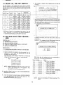
11_ SETUP OF THEiDIP'-SWITCHi' .,
5. The message as sti9YY~rf~~:~Frg. 7"a'~pJiih~~)wt)e'n3:tj'~ t~;i
normally.
__
_----------_. . _.,---The DIP switc~(t'h the interface PC boar'dls\ised to estaolish
th~si~t~ ,of thErQutput -co'nir-QI~5igr::!al.s Jmmej:fiately after powe~
- ...
·
!
Fig.
2,-----------,::-.-,-,--,-:-:-:--,
~1{S-~Efef~~'-S~itc~-e-d dn.;:thlltlg!c~1 pol~rj~y "2f ,t~e;9~tPjjt;'cohtr6~
~rgn~ls, ~tc.
- ---_. - -- -"~i -
,,
i
-,
L~.1tcf:t-:~ .
I ,
'
Switch
position
~ig!1al
"I
:-~;
· ii
I
OFF
.
-I
3
- -
I:'
•
-"
OF.F
Positive
,'/
OFF
(IoW lavel)
ON°,
dN
912_
(hiah i'evert
(high IEllieD-
off
011
I"~c
I, -
qN
j
Of-F
(high le~el!
OFF'-
ON
(high le~el)
(Iow le~el)
ON
-
DIP
'-'-
I
OFF
(high [aveil
ON
OFF
(low!evei)
(high Lev,ell
OFF
ON
logic
(Iow level)
Jhigh level)
Negative
logic'
Positive
logic
ON
OFF
Negative
logic
Positive
, logic
- (hign levell--
(low'l~vell
OFF
--"-Oi\J
(high leve;r)
how le~en
ON
_
(high le'!ell_
OFF
(Iow level)
Negathre
ON
":Iogi(;
, (high levell
OFF
(Iow level)
>11
(high I~vel)
--i'OFF
(Iow level)
,I
If there is any failure, the bit in failure will be shown on
the display.
Example: The m~ssage-,!as-sho~m 'i:Mlow-'app~ear's \..vhen bits
1 and 2 of the I/O port is in failure.
'i'_)'
-I'
.' ,"
P).M.~:"lE02JR.S2~2C_IIE ~WB) .', ' . C ' , . . . '
c(:!)" i:Jia~n6~Hc' iii6gr~mdisketie (UK9G-".oH3 CSZZ)
(4) C.ble(UKO-GG0078CSZZ)
• '.',
(;1-
MZ-3500 GPl!O CHECK OK 1\·'1
'.I
~99Js:r,~h'ir~vd, :f; -~:. 'n .); ,:,'
(1) MZ-3500 Personal Computer
')
..-
READY
- ON
12_ MZ-1E02 (GPIO}'TE$TPROCED-' ;~J~,!EJ'
'
")\.1
Space Key)'
'Tuin'.1! dip switch"" Off;:bUhe .~dal'd:ta;be:tested when
the above message is displayed, then push:We SPACEBAR.
The test is satisfactory when the following message appears
. -- after-depressronoftheSPACEBAR.
I
.. ";..;,
- (Push
ON
(Iow ievell
~ The: teve-I of each -bit 'in' accoraance with Syntax :3 o.f the
G'OUT -c~mrhand, Cir the value of.the numeric expression Z
in accordanc~; ~i~~_I,~XPH;tln,;4,-f?f.thJ!:~~,IT ?omman~,.
,.::));)';'1::':;;; '~ __ j
SWaN
,-
_:Qutput level
in manual mod.a
Positive
logic
Negatiye
logic _
[evel)
,(jowON,
010-
:
po~arjtv
ON.
6N
•• :
Logical
(loiN rev'el)
_ 09 __
(-
Initial
state
OFF
OFF
C'
1
.~
I
'! --
ends
'.
• ••
ii~
I.
,
READY.
>11
'11
1 MZ-35.oO GP I/O CHECK ERROR
I
Testproce"diire! .'
•!, !.J'
j
i
I .~
• i '-,
J,.Fi,~jt,h.~j9Btiqoal,slqtJ
2.
2 bit······ERROR
Insert the board to be tested in the slot number 3 or 1 of
,Cha,ll,{lel 0.,. And, inse.rt the, testing board in the slot
number 2 or 4 of Chan·nel 1.
Keep;~he-'board t~ be tested in Ch-ar:mel--O- at all times and
. change the_'testing boar_q in CJ;.annel' 1 after each test.
Fig .. 1
~
'.'.
,SlOt.··
,3
_
1·.
4
2.
~~--~-
Channel.o Channel 1
NOT~': : B~.tore -lfjsertir;i.g the ,bo~rd ,in the:,slot;-_make ,sur:e
that all dip s~itches are in OFF:'position. Any
dip-'switch turned ON must_be set OFF.
,3.'- Connect
. :~edicijted
4.
1 bit······ERROR
p.n.! pn,the.baqk of the,MZ-3500.
b~ards'
using' the cable' (UKOGGOO.78CSZZ)
fq'r this service.
,
Error may also be iniJicated when the SPACEB~R is
pushed after turning all'dip switches ON.
(Error message)
_tbit ....
2 bit .........
3 bit .........
4 b-i t .........
,5 bj t .. : ......
16 bit .......
-7,bit .........
8 bit. .........
9b It
lOb i t
n-br t
12b It·
Insert the diagnostic program diskette (UKOG-0143CSZZ)
in the MZ-3500 floppy disk drive and turn power on. The
test starts automatically after power on.
SIgnal
line 01 or 11 in failure
• 02 or -12 in failure
• 03 or 13 in failure
1- 04 or 14 in failure
• i
05 or 15 in failure
• 06 or ,16 in failure
• 07 or 17 in failure
1- 08 or 18 in failure
Dip switch
• 09 or 19 in failure rem~iils'ON.
• 010 or \lO in failure •
• , 011 or III in -f~ilure
';' 612'~r:112 i~fai1ur'~
•
ERROR
ERROR
ERROR
ERROR
ERRPR
ERROR
ERROR
ERROR
ERROR
ERROR
E,RROR
; I , . ,I;
ERROR
;)
,
..
"
~
'-,
. , , I.. ' I,
,- ,
:
,
,
NOTE: Be· sure to turn power off before accessing of the
board.
10
~
~
."v
IREQ 0
R' )~1I-4
'"
2BB
o ;oV
,co '"'''eo
-15
,
le
i17
J
:.tLsoo
LS27
B
,,'"
1
_
2'(12
lOOP
1R:
~ 3 LSIO
.e
~6
,-
'"
se
WR
,
a
~'"
m
~
e
~
LS3Z
~
LS3Z
~4B
V
'00
,
D1
30 U4
D3
~l 00
~21l'
l::::::J.
00
"--" '"
PI
I---l!'
'IJ [)7
•M
-i"
~:i
"wo
''''
100
cs
,\9
\10
B AO
'00
~IWE
100
~O
CS
20 OF.
.....:=:J:S
~A9
q,
R1~
BA6
P'AZ
~AI
~A3
P
A4
~AS
2\I1'E
100 20 DE
I"
16
,J1;= R
~
~ .~B
F;A~
\'«121
2,\
·5
8Z55
V"" "
~
110Vce
""~
9
, "
e Al
, '"
4A
58nS
G:>:~ rlr
Voo
Vc<,~
12
07i
DSp.t::
DS~
DIm:=D21W-1J3m-D4Hi--
D01~
f);~
D4~
g~lW--
~A U3Ht-D~m::=
Dll-lJ.--
9
"",~3821658725
1__,' ,"
""Ii¥==
4D
13 L500
"
cC
7 G:\D
,
1,
14
IS
PC2 17
'PCl'6
" "
~2~
reo
~~~
1'!\.5 38
37
n4~
m
T'A2
'"
,"
4
..~
,
,'eo ,
""'b I
IL
'""'~
f,~lt~
"". ::
~
':
'00" ;; """" ,c.
eo, :.
wo
' " 0 ; / ; ' . w"
,,''''
"
4
~
6
3
'" cooo
2
'1"\'
5
" ''''
,
11
r; '" ,
12
Vcc
~ ,rCC,
10
'lee
~
~ ""
"
"
" '';;'
2
T 58
~--'
3C
"
rfiC\
~
12
"m
,co'" •
AO
" ""
-+
01
~RO~rl-4
10
5
CKCL
""
41P
~: 'w
;J;'"W ""'"
~ ~ ~o
AI210
"R
,.c
2
All 9
2L~ ~
"","
mu ,,,'"
,0
,
I.S27
,.,
V"
10
DP~9
~:;[c:~3~12
I 5]26 4
,""
~_
j
,~6 1
.'15
A7
"0
,"0"'
"."
o '" ,
'0"'''''
V" 0
0"
.- ;;~
co m
'H ,; •• """"'''
>V"",,"
c
I.
IL
:=;l
f
~
5 I.SM
6
-
,
=-~
7L-2
:<
-"
.1t.1C
3
'"
~llm
"""' ~
<f.1!1
;/;
!o lA \>' ;;
"'
\~;;I;
~-(,]...9 ;;
IS
1.0><6'In
!.i..
~
~
~
~
lKX4
~p~
1 3 (291
0
1B
~!l
""
14 ClII
""
""
--.,
--{Q)
0
--@
~8
~51
~l
1 12 ~11
111
110
""
""
-@J
-@
-@
0
0
~h
o\2('l;l:
-@ I 9
-@c
~
~
,"
"
"
s::
>
~
:xJ
c
~
s::
:::r:
m
(J)
(')
(')
III 21'
(
~
N
'"
Thc C'-cn numbers nre GXD'"
G:>:D-'----"--_
0.1,,' 12\' <15
ycc--t----r----
.....
",
17,
"
"
"
o~nn~NOr
oc o '1~
-(9)C
-@~
{Q)C
-<0"
-<wo
C
0"
rC-
~
~
00
--{Q) 0
Vcc
'"..r::::
• ><0-' '"
:\ia.~
1Q,..,~11~
,~~
6
, :r.f'---- '"
,
10
LSHX2 41Px12
3
::tFc' " P!I 'S- ~
5
lKX
~U38 ~
~
e
10 le
.E~
I~a="'::
1::8~
~.u=:=
~~
, ~ a="'::
~
",,; ~
llt?~ ..
~1D
~e ~1S,~
v"
----1.J..1. 2C
lOKX4:
IKXB
Vo,
Cable side
" "c::"'::
7438X2
NI
s::
~
.....
0
N
trl
-
~
t:<
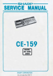
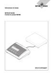
MZ·1E0;2
14. MZ-1E02 COMPONENT LOCATION
CPU Side
B
GNO
Vcc
RO
DO
02
04
06
AD
A2
A4
A6
No
Cable Side
A
1
2
3 GNO
4 Vcc
5
6 SYSRES
7 ijiffi
8I 01
03
9
05
10
07
11
A1
12
A3
13
A5
14
15
A7
A8
A10
A12
16
A9
17
An
18
19
20
TORQ 21
Ml
22 MREQ
23
24
2&
26
27.
RoM x 28
29
GNO
30 SLOT
GNO
(PARTS SIDE)
12
2
4
6
8
10
12
14
16
18
20
22
24
26
28
30
0
0
0
o.
1
2
3
4
5
6
7
8
9
10
0
0
0
0
0
0
0 11
0 12
i 1
i .2
i 3
1
3
5
7
9
11
13
15
17
19
21
23
25
27
29
32
34
36
38
40
42
44
46
48
GNO 50
i
i
i
i
i
i
i
i
i
4
5
.6
7
8
9
10
11
12
31
33
35
37
39
41
43
45
47
49
----
(PARTS SIDE)
MZ·IE02
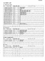
15. PARTS LIST
[I] Electronic parts
NO..
PARTS caDE
1
2
3
4
5
LANGTI013ACZZ
QSOCZ6424ACZZ
QSOCZ6440ACZZ
QSW Z9660KCZZ
XBPSM30P06KSO
6 RMPTC4 10 2QCKB
7 RMPTC~ lO3QCKB
8 RMPTC8102QCKB
9 VCCCPA1HH101J
10 VCCSPU1HL470J
11 VCEAAA lCW3 3 6M
12 VCKYPA1HB102K
13 VCTYPA lNX 1 04M
14 VHiM58725P
15
15 VHiM74LSOO/ 1
16 VHiM74LS04/ 1
17 VHiM74LSIO/ 1
18 VHiM74LS126
1
19 VHiM74LS14/ 1
20 VHiM74LS27/ 1
21 VHiM74LS32/ 1
22 VHiM74LS74/ 1
23 VHiM74LS86/ 1
24 VHiM7438/// 1
25 VHiUPD8255/ 1
26 VRD RV2EYIOOJ
27 VRD RV2EYIOIJ
IlJ
PRICE
RANK
NEW
MARK
AH
AE
AG
AR
AA
AC
AC
AD
AA
AA
AB
AA
AB
AZ
AE
AE
AE
AH
AM
A F
AF
AG
AF
AE
AV
AA
AA
PART
RANK
C
C
C
B
C
B
C
C
C
C
C
C
C
B
B
B
B
B
B
B
B
B
B
B
B
C
C
DESCRIPTlaN
Angle for connector
le socket 24pin)
le socket 40pin
Dip SW.
Screw
Block resistor l.OK,nX4 1/8W +10 0
Block resistor lOKOX4 1/8W +1O%) _
Block resistor (l,OKnXB 1/8W +10%)
Capacitor 50WV lOOpF
Capacitor 50V 47pF
Capacitor 16WV 33"F)
Capacitor 50WV 1000pF
Capacitor 12V O.l"F
IC
IC
IC
IC
IC
IC
IC
IC
IC
IC
IC
IC
Resistor lOOJ O.5W
Resistor 1/4W lOOn. +5%)
Accessary
NO.
1
2
3
4
5
6
7
PARTS CaDE
SPAKA1087ACZZ
SPAKA 114 OACZZ
SPAKA 1141 ACZZ
SPAKCl 0 8 6ACZZ
SPAKC12 4 2ACZZ
TiNSEI068ACZZ
RMEMRIOQ6AC19
PRICE
RANK
AC
AH
AA
AF
AP
BB
BF
NEW
MARK
PART
RANK
D
0
N
N
D
D
D
D
DESCRIPTlaN
Packing
Packing
Packing
Pack in
cushion for master
cushion for 1 E03
cushion for 1E03
case for master
Packinll case
Instruction book
Master media
W MZl C19(MZl E02)
NO..
PARTS CaDE
1 SPAKAll05ACZZ
2 SPAKC1206ACZZ
4 TSELF1002ACZZ
PRICE
RANK
AD
AU
AA
NEW
MARK
PRICE
RANK
BK
BN
NEW
MARK
N
N
N
PART
RANK
D
D
D
Packing- cushion
Packing case
Sealing label
PART
RANK
E
E
Diag media
Cable unit
DESCRIPTlaN
[I] Taals
NO..
PARTS CaDE
1 UKOG O143CSZZ
2 UKOGG0078CSZZ
DESCRIPTlaN
13
,I"~
,
SHARP
SHARP CORPORATION
Industrial Instruments Group
Reliability & Quality Control Department
Yamatokoriyama, Nara 639-11, Japan
Y.F
Jun. 1983 Printed in Japan