1
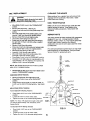
Owner's Manual
CRRFTSMRW
42-inch Universal
Tow Behind
POWER MOWER
Model no. 486.243291
CAUTION:
Before using this power mower,
read this manual and follow all
its Safety rules and Operating
instructions.
Sears, Roebuck
and Co, Hoffman
•
•
•
•
•
Estates,
Safety Instructior_:_
Assembly
Operation
Maintenance
Parts
IL 60179 USA
TABLE
OF CONTENTS
_/ARRANTY ................................................................ 2
b_,FET'( RULES ....................................................... 2-4
._ONTENTS OF CARTON ........................................... 5
_SSEMBLY .............................................................. 6-8
_IRING SCHEMATIC ................................................. 9
LIMITED
ONE YEAR WARRANTY
OPERATION ......................................................... 10-14"
MAINTENANCE .................................................... 15-17
SERVICE AND ADJUSTMENT .............................. 18,19
STORAGE ................................................................. 21
REPAIR PARTS .................................................... 22-33
ON POWER
MOWER
ATTACHMENT
For one (1) year from the date of purchase, If th(s Power Mower is maintained, lubricated and tuned up according
to the instructionsin the OwneCs Manual, Sears wil( repair or replace, free of charge, any parts that-,re
defective in material or workmanship.
This Warranty does not cover:
• Expendable items which become worn during normal use, such as belts or cutting blades.
• Repairs necessary because of operatorabuse, negligence,Improper storageor accidentor the.tailureto maintain
the equipment according to the instructionscontainedin the Owner'sManual.
• Power Mower Attachment used for commercial or rental purposes.
WARRANTY SERVICE IS AVAILABLE BY RETURNING THE POWER MOWER TO THE NEAREST SEARS
SERVICE CENTER IN THE UNITED STATES,
ThisWarranty gives you specificlegal rights,and you may also haveother rightswhich may varyfrom state to state.
SEARS,
ROEBUCK
AND
CO., D/817 WA, Hoffman
Estates,
IL 60179
SAFETY RULES
Safe Operation Practices for Tow Behind Mowers
A
L
•
•
•
,,
•
WARNING: This cutting machine is capable of amputating hands and feet and throwing objects. Failure to
observe the followingsafety instructionscould result in sedous injuryor death.
GENERAL OPERATION
Read, understand, and fotldwall instructionsin the
manual and on the machine before starting.
Read th!s operator'smanual carefully. Become
familiar with the controls and know how to operate
your mower properly.
Only altow responsibleadults, who are familiar with
the instructions,to operatethe machine.
Clear the area of objectssuch as rocks,toys, wire,
etc., which could be picked up and thrown by the
blade,
Be sure the area is clear of,other people before
mowing. Stop machine if anyone enters the area.
Never carry passengers.
Do not mow in reverse unlessabsolutely
necessary, Always look down and behind before
and while..,acking.
o
41
2
Be aware of the mower dischargedirectionand do
not point it at anyone. Do not operate the mower
withoutthe guard in place.
Slow down before turning.
Never leave a running machine unattended.
Always turn off blades, and stop engine.
Turn off blades when not mowing.
Mow only in daylight or good artificiallight.
Do not operate the machine while under the
influence of alcohol or drugs.
Watch for traffic when operatingnear or crossing
roadways.
Use extra care when loading or unloadingthe
machine into a trailer or truck.
Do not attempt to operate your tractor or mower
when not in drivers seat.
Disengage power to mower and stop engine when
transportingor not in use.
•
•
•
•
•
•
•
•
•
•
•
I1.
Exercise special care when mowing aroundfixed
objects in order to prevent the blades from stdking
them. Never deliberately run tractor or mower onto
or over any foreign object.
Use mower only as the manufacturer intended and
as described in this manual.
Do not operate mower if it has been dropped or
damaged in any manner. Always have damage
repaired before using your mower.
Always wear safety glasses or eye shields when
starting and while using your mower.
Dress properly. Do not.operate mower when
barefoot or wearing open sandals. Wear only solid
shoes with good traction when mowing.
Always make cutting height adjustments before
starting your mower. Never attempt to do this while
the engine is running.
Keep your eyes and mind on your mower and the
area being cut. Do not let other interests distract
you.
Do not put hands or feet near or under rotating
parts. Keep clear of the discharge opening at all
times.
Before cleaning, inspecting, or repairing your
mower, stop the engine and make absolutelysure
the blade and all moving parts have stopped. Then
disconnectthe spark plug wire and keep it away
from the spark plug to prevent accidental starting.
Do not operate your mower if it vibrates
abnormally. Excessive vibration is an indicationof
damage; stop the engine, safely check for the
cause of vibration and repair as required.
Never operate your mower without properguards,
plates, or other safety devices in place.
SLOPE
DO NOT:
•
Do not tum on slopes unlessnecessary, and then,
turn slowly and gradually downhill,if possible.
•
DOnot mow near drop-offs, ditohes, or
embankments. The mower could suddenlyturn
over if a wheel is over the edge of a cliff or ditch, or
if an edge caves in.
• Do not mow on wet grass. Reduced traction cot_ld
cause sliding.
IlL
Tragic accidents can occur if the operatoris not alert to
the presence of children. Children are often attracted
to the machine and the mowing activity. Never assume
that children will remain where you last saw them.
•
Keep children out of the mowingarea and under
the watchful care of another responsibleadult..
Be alert end turn machine off if children enter the
area.
Before and when backing, look behind and down
for small children.
Never carry children. They may fail off and be
seriouslyinjured or interfere with safe machine
operation.
Never allow childrento operate the machine.
Use extra care when approachingblind comers,
shrubs,trees, or other objectsthat may obscure
vision.
•
•
•
•
•
IV.
•
OPERATION
Slopes are a major factor related to loss-of-controland
Upover accidents, which can result in severe injuryor
death. All slopes require extra caution. If you feet
uneasy on it, do not mow it.
DO:
•
Mow up and down slopes, not across.
•
Remove obstacles such as rocks,tree limbs, etc.
•
Watch for holes, ruts, or bumps. Uneven terrain
could overturnthe machine. Tall grass can hide
obstacles.
•
Use slow speed. Choose a low gear so that you will
not have to stop or shift while on the slope.
,P Follow the manufacturer's recommendationsfor
wheel weights or counterweightsto improve
stability.
•
Keep all movement on the slopes slow and gradual.
Do not make sudden changes in speed or direction.
•
Avo_ starting or stopping on a stope. If tires Lose
traction, disengage the blades and proceed slowly
straight down the slope.
CHILDREN
•
•
•
•
•
•
SERVICE
Use extra care in handling gasolineand otherfuels.
They are flammable and vapors ere explosive.
• Use only an approved container.
,,* Never remove gas cap or add fuel with the engine
running.
• Allow engine to cool before refueling. Do not
smoke near or while operating mower.
• Never refuel the machine indoors.
• Never store the machine or fuel container inside a
room where there is an open flame, such as with a
gas water heater.
Never run a machine inside a c!osed area.
Keep nuts and bolts, especially blade attachme_
nuts, tight end keep equipment in good conditio;_.
Never tamper with safety devices. Check their
proper operation regularly.
Keep maciline free of grass, leaves, or other debris
build-up. Clean oil or fuel spillage. Allow machine
to cool before storing.
Stop and inspect the equipment if you stdke an
object. Repair, if necessary, before restarting.
Never make adjustments or repairs with the engine
running.
•
•
Mower blades are sharp and can cut. Wrap the
blade(s) or wear gloves, and use extra caution
when servicingthem.
Check brake operationfrequently, Adjust and
service as required.
Look for this symbol to point out
important safety precautions. It
means CAUTION!II BECOME
ALERTIII YOUR SAFETY IS
INVOLVED.
CAUTION: Always disconnect spark
plug wire and place wire where it
cannot contact spark plug in order
to prevent accidental starting when
setting up, transporting, adjusting
or making repairs.
4
Please read and keepthis manual. The instructionswill
enable you to assemble and maintain your Power
Mower property. Always observe the "Safety Rules."
Record serial number and date of purchase in space
provided below.
MODEL
NUMBER:
486.243291
SERIAL
NUMBER:
DATE OF
PURCHASE:
The model and serial numbers will be found on a
plate attached to the right side of the Drive Housing.
You should record both serial number and date of
of purchase and keep in a safe J_lacefor future
reference.
internal combustion engine and should
WARNING: This unit is equipped with an
not be used on or near any unimproved
forest-covered or grass-covered land
unless the engine's exhaust system is equipped
with a spark arrester meeting applicable local or
state laws (if any). If a spark an'ester is used, it
should be maintained in effective working order by
the operator.
In the state of California the above is required by
;law (Section 4442 of the CaliforniaLPublic Resources
Code). Other states may have similar laws. Federal
laws apply on federal lands. A spark arrester for the
muffler is available through your nearest Sears
IAuthorized Service Center.
PRODUCT
SPECIFICATIONS
HORSEPOWER:
8.0
DISPLACEMENT:
19.4 CU. IN.
GASOLINE CAPACITY:
GASOLINE TYPE:
3.QUARTS
UNLEADED REGULAR
OIL TYPE (API-SF/SG):
SAE 30 (ABOVE 32°F)
SAE 5W-30 (BELOW 32°F)
OIL CAPACITY:
3.0 PINTS
SPARK PLUG:
(GAP: .030")
CHAMPION RJ19-LM
STD361458
VALVE CLEARANCE:
INTAKE: .005 - .007 IN.
EXHAUST: .009 - .011 IN.
BLADE BOLT TORQUE
35-40 FT. LBS.
TIRE PRESSURE
10 PSI
WIDTH OF CUT
42 INCHES
T I
,,
i
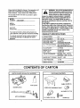
CONTENTS
PARTS PACKED SEPARATELY IN CRATE
PARTS
MOWER
DECK
OF CARTON
PARTS BAG CONTENTS
B_AG
CABLE GUIDE (2)
OPERATOR PRESENCE SEAT
318 CABLE CLIP (3)
HITCH ASSEMBLY _
1/2 CABLE CLIP (3)
_SCREW
(3)
ii
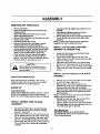
ASSEMBLY
REMOVING UNIT FROM CRATE
•
•
•
•
•
•
•
•
•
t
Remove top boards.
Remove two Boltsfrom front of crate which hold
shipping anchors.
Remove two Boltsfrom bottom at rear of crate
which hold shipping anchors.
Remove Hitch Assembly and Parts Bag from crate.
Remove front of crate.
Roll Mower ronsardout ofcrate.
Remove Roller Bolt from Front Roller, remove
shipping anchorsand reinstall Roller Bolt.
Remove Nuts from Height Adjustment Stropsand
remove shipping anchorsfrom each side of inower.
Reinstall Nuts to Height Adjustment Straps,then
loosen 1/4 tum to allow straps to pivotfrae!y.
Check all lOOseparts and bag contentsagainst
Crate Contents and Bag Contents illustrationon
page 4. If any part is missing or damaged contact
the store where you pumhased the unit.
•
Assemble a 3/8 Flat Washer onto a 3/8-16 x 2-1/2
Hex Bolt.
•
Insert Bolt and Wisher through slot of Rear
Quadrant and hole in Towbar Tube.
• Secure tightlywith 3/8-16 Lock Nut then loosen Nut
114turn to allow tube to pivot freely inside Rear
Quadrant.
NOTE: Tow'oarTube must pivot freely inside Rear
Quadrant when latch is pulledfrom notch_
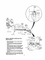
INSTALL CLUTCH CABLE AND WIRE
HARNESS TO TOWBAR TUBE.
.
•
•
•
Before starting to assemble mower,
remove spark
plug wire from plug of
CAUTION
mower engine.
OPERATOR
•
[
INSTALL CLUTCH CABLE TO THE HITCH
ASSEMBLY
ORIENTATION
When dght and left are mentioned in this manual, it
means your right and your left when you are seated
behindthe wheel in the operating position.
•
Remove one 1/4 inch Nut and Boltfrom the eyelet
of the Clutch Cable. (See Fig. 1)
• Remove one of the 5/16 inch Nuts from the
threaded end of the Clutch Cable Housing and turn
the second Nut all the way ontothe threads.
Insertthe Clutch Cable and the loose 5/16 inch Nut
through the slotted hole in the Cable Guide of the
Hitch Assembly.
NOTE: The loose 5/16 Nut must be cocked sideways
slightlyto get it throughthe Slot.
•
Reinstall the loose 5116inch Nut ontothe Clutch
Cable Housing to secure Cable'Housing.
•
Alignthe eyelet of the C_utchCable with the hole in
the Mower Blade Clutch Lever and secure with one
1/4 inch Bolt and one 114inch Nut.
ENGINE OIL
VERY IMPORTANT:
Engine must be filled with oil before operation. See OIL
& FUEL RECOMMENDATIONS in engine Owner's
Manual for correct filling instructionsand oil fill capacity.
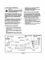
INSTALL TOWBAR
QUADRANT
TUBE
Unwrap the Wire Harness and the Clutch Cable
from Around The Engiee.
Lay the Clutch Cable alongthe left side of the
Towbar Tube and the Wire Harness along the right
side of the Towbar Tube.
Install three 3/8" Cable Clips on the Clutch Cable
and three 1/2" Cable Clips ontothe Wire Harness.
Align all six Cable Clips with the holesin the Towbar
Tube and secure them with three #10 Self-Tapping
Screws.
TO REAR
Cut and remove the Plastic Tie which holdsthe
Wire Harness and the Clutch Cable to the Rear
Quadrant (See Fig. 1)
Remove two 3/8 Bolts, two 3/8 Lock Nuts and one
3/8 Flat Washer from the rear of the Towbar Tube.
Place tube into Rear Quadrant, align holes, insert
3/8-16 x =.1/2 Hex Boltthrough rear hole of tube.
Secure tightlywith 3/8-16 Lock Nut then loosen Nut
1/4 turnto allow tube to pivot freely Inside Rear
Quadrant.
See DRIVE TENSION in the SERVICE AND
ADJUSTMENTS Section of this manual for proper
Clutch Cable adjustment.
R
ONIOFF
SWITCH
HG NUT
\
BOLT3/8 X 2-t/2
#10 SELF
TAPPING
SCREW_.
"1
T WASHER
3/8 CABLE CLIP (3)_i
1/2 CABLE CUP
REAR
Q UADFL_NT
MOUNTING
ERACKET
I
_
, CLUTCH CABLE
ANCHOR
TOW BAR TUBE
#
" SWITCH
_
WIRE HARNESS.
3/8
LOCK
HITCH ASSEMBL
NUT
MOUNTING
MOWER BLADE
CLUTCH LEVER
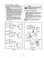
INSTALL THE WIRE HARNESS AND THE
ONIOFF SWITCH
Slide the Wire Hamess under the Cable Anchor of
the Hitch Assembly.
• Connect two 114 Female Spade Connectorsfrom
the Wire Harness to the prongsof the ON/OFF
Switch.
•
Insertthe Seat Switch Plug of the Wire Harness into
the Hitch Assembly, Rulnng it up and throughthe
righttop side of the Switch Mounting Bracket.
•
Remove one Ring Nut from the ON/OFF Switch and
adjustthe second Ring Nut 1/4 inch from the top of
the threads.
•
Insertthe ON/OFF Switch up.through the Switch
MountingBracket and secure it by reinstalling the
Ring Nut.
NOTE: The notch in the threads of the ON/OFF Switch
must face toward the "ON" of the ON/OFF Switch Decal
to insure proper ON/OFF control.
ANCHOR
BOLT 114 X 3/4
HITCH
ASSEMBLY
SWITCH
MOUNTING
•
RING NUT
NUT 5116(2)
CABLE
GUIDE
WIRE HARNESB
7
SEAT 8WrTCH
CONNECTOR
LOCK NUT
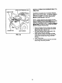
INSTALL OPERATOR
TRACTOR
OPERATOR PRESENCE SEAT
PRESENCE SEAT TO
CABLE GUIDE
\
Your Mower is equipped with and Operator Presence
Seat to provide for your safety. The Operator Presence
Seat must be installedon the seat of the tow vehicle
and must be plugged in to the Wire Harness of the
Mower for proper operation of this unit.
NOTE: In order to start the mower enoine you must
have the Operator Presence Seat.plugged into the Wire
Harness of the Mower and the Mower Blade Clutch
Lever in the disengaged position. LD_L_JPJ_II_J_t
Mower Blades You must be seated on the Tow Veblcle
and on the Operator Presence Seat,
•
CONNECTOR
SEAT STRAPS
•
•
FIG. IA
•
8
Place the Operator Presence Seat on the Tractor
Seat with the Wire towardthe bottom and secure
with the seat strap. (See Fig. 1A)
Lift Tractor Seat and install a cable guide in the
middle of the Tractor rear fendera.
Place Operator Presence Seat Wira into Cable
Guide with the connectortoward the rear so as to
connectwith the Seat Switch Plug of the Wire
Hamess.
Lower Tractor Seat
Connect Operator Presence Seat wire to the Seat
Switch Plug of the Wiring Harness.
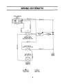
WIRING SCHEMATIC
iiii
START INTERLOCK
MODULE
RED 16"
BLACK 16"
P_BLUE
13".
IGNITION
UNIT
CLUTCH IDLER
INTERLOCKSWITCH
(DECLUTCHEDPOSITION)
RED 72"
I.L
ONIOPF SWITCH
(OPEN IN ON POSITION)
BLACK 72"
SEAT SWITCH _,
(NOT OCCUPIED) -
ENGINE
GROUND
L
__
_.I
GROUNDING
CONNECTOR
A
C)
v
NON-REMOVABLE
CONNECTIONS
REMOVABLE
CONNECTIONS
9
I
•
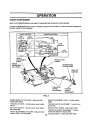
OPERATION
KNOW YOUR
MOWER
READ THIS OWNER'S MANUAL AND SAFETY RULES BEFORE OPERATING YOUR MOWER.
Compare the illustrationswith your mower to familiadze yourselfwith the locationof various controlsand adjustments.
Save the manual for future reference.
CHOKE CONTROL
OFF
POSITION
THROTTLE
CONTROL
FULL
POSITION
HEIGHT
ADJUSTMENT
STRAP
RECOIL START
HANDLE
MOWER BLADE
CLUTCH LEVER
TOW HIT_
OFFSET
ADJUSTMENT
R
TOW BAR
HEIGHT
ADJUSTMENT
FIG. 2
MOWER BLADE CLUTCH LEVER - Starts and stops
mower blade rotation.
HEIGHT ADJUSTMENT STRAP - Controlscutting
height.
THROTTLE CONTROL - Controls engine speed, engine
shut-off.
TOW BAR HEIGHT ADJUSTMENT - To level mower
front to rear.
SHUT OFF CONTROL - Used to shut off mower engine
from tractor seat.
RECOIL START HANDLE - Used to start engine.
HEIGHT ADJUSTMENT LIFT LEVER - Raise and lower
mower to diffe.._nt_,J*,tlngheights.
TOW HITCH OFFSET ADJUSTMENT - To adjust
mower deck offset from tractor center.
10 CHOKE CONTROL - Opens and closes choke.
The operation of any mower can result in foreign objects being thrown into the ayes,
which can result In severe eye damagel Always wear safety glasses or eye shields
before starting your mower and while mowing. We recommend wide vision safety mask
for over the spectacles or standard safety glasses,
CHILDREN
Tragic
accidents
can Occur if the operator
is not alert to the presence
Children are often attracted to the machine and the mowing
assume that children will remain where you last saw them.
HOW ToUSE
YOUR MOWER
ATTACHING
STOPPING
•
•
•
•
•
Move blade clutch lever to Off position.
Move engine shut off switch to Off position.
Move engine throttle to Stop position.
•
STARTING
•
•
•
•
•
•
•
MOWER TO TRACTOR
Place mower behind tractor and back tractor up to it
for attaching. (See Fig. 3)
Slide tow bar of mower over tractor drawbar so that
the hitch pin holes line up.
Insert hitch pin until it extends through the bottomof
the tow bar.
Insert hair cofter pin through hitch pin.
HITCH PIN"
Sit on tractor seat.
Raise blade clutch lever to Engage position.
Operate tractor at medium ground speed, 3-4 MPH.
Refer to Safety Rules on page 3 regardingoperation
of mower on slopes.
TRACTOR
DRAWBA.R
TRANSPORTING
FIG. 3
•
•
Never
Move engine shut off switch to On position.
Move engine throttle to Ful! position.
Move choke to full
Move blade clutch lever to Off position.
Pull start rope.
Move engine choke to Off position after engine
starts.
USING
•
•
•
•
activity.
of children.
Shut off engine.
Place mower deck in the highest positiondirectly
behindtractor.
CAUTION:
Never operate the mower without
discharge chute coyer in its proper
place.
I
11
CUTTING HEIGHT INFORMATION
•
CAUTION:
1
Shut
off mower
engineplug
andbefore
remove
spark|i1
plug wire
from spark
making
any adjustments to mower.
J
The cutting height ra_e is approximately 1-1/2 to 4-1/2
inches. The_heightsare measured from the ground to
the blade tip with the engine not running. These heights
are approximate and may vary depending upon soil
conditions,height of grass and types of grass being
mowed.
The average lawn shouldbe cut to approximately 2-1/2
inches dudngthe cool season andto over3 inches
duringhot months. For healthier and better looking
lawns, mow often andafter moderate growth.
For best cutting performance, grass over6 inches in
height should be mowed twice. Make the first cut
relatively high, the secondto desired height.
•
Reassemble clevis pin to the height adjustment
strap and secure with hair cotter pin.
Make sure that bothside height adjustmentstraps
are adjusted to the same height.
FRONT TO BACK RAKE ADJUSTMENT
To obtain the best cutting results,the mower housing
should be adjusted so that the front is approximately
1/4" to 3/4" lowerthan the rear. To check front to back
adjustment measure from the bottom edge of the deck
to the ground at both front and rear of the deck.
TO ADJUST MOWER FROM FRONT TO BACK
•
•
•
•
Remove two hair cotter pins from two clevis pins in
the tow bar adjustment.. (See Fig. 4)
Remove two clevis pins from tow bar adjustment.
Raise or lowerthe'tow bar to obtain the properfront
to back adjustment.
Reassemble two clevis pins to tow bar adjustment
and secure with two hair cotter pins.
CUTTING HEIGHT ADJUSTMENTS
•
•
•
•
To adjustthe mower cutting height remove hair
cotter pin from clevis pin in the Height Adjustment
Strap. (See Fig. 4)
Apply down pressureto height adjustment lift lever.
Remove the clevis pin from the height adjustment
strap.
Move height adjustment strap up or downto align it
with the desired holP in the height adjustment strap.
HEIGHT ADJUSTMENT
LIFT LEVER
CUTTING
HEIGHTS
1-1/2 in.
2 in.
in.
in.
/
L
CUTTING
HEIGHT
GROUND LEVEL
FIG. 4
BLADE
TOW
HITCH
OFFSET
ADJUSTMENT
This tow behind mower has been designed to run offset
from the center of the tow vehicle to give additional
cuttingwidth.
• The adjustabletow hitch of this mower can be set in
the straight positionor to either side in one of three
offset positions, 15", 29", and 39". (See Fig. 5)
•
When cuttingwith a tow vehicle already equipped
with a 42", 46", or 50" mower, we recommend using
the 3g" offset, When cuttingwith a tow vehicle
equipped with 36", 38", or 40" mower, use the 29"
offset position. When cutting heavier grass or
when conditionswarrant, adjustthe mower to the
15" offset position.
•
If tow vehicle is not equipped with a mid-mount
mower the hitch can be adjusted to a straight
position, but we recommend usingthe offset
positionto eliminate grass being crusheddown by
the tow vehicle.
CAUTION:
Shut off mower engine and remove spark
plug wire from spark plug before making
any adjustments to mower
TO ADJUST THE OFFSET HITCH
•
•
•
Pull back the pivot latch from the notch of the front
quadrant. Adjust the hitchtube to the desired offset
and release the pivot latch into the notch of the
quadrant. (See Fig. 6)
Pull back the pivot latch from the notch of the rear
quadrant. Adjust the hitchtube to the corresponding
notch of the front quadrant and release the pivot
latch into the notch.
IMPORTANT: The hitch tube must be assembled to
• the same offset notch in both the front and rear
quadrants.
15" OFFSET
;"OFFSET
LATCH
39" OFFSET
39" OFFSET
LATCH
FRONT QUADRANT
29"OFFSET
'i
L
REARQUADRANT
FIG: 5
FIG. 6
13
BEFORE
•
STARTING
MOWING PROCEDURES
ENGINE
CAUTION:
Tragic accidents can occur if the
operator is not alert to the presence of
children. Children are often attracted to
the machine and the mowing activity.
NEVER assume that children will remain
where you last saw them.
Fill engine with oil (See MaintenanceSection of
this manual for proper procedure and requirements)
Add Gasoline, Fill Fuel tank using fresh clean
unleaded gasoline.
•
I cAuT'°N;
II,
Fill to bottom of fuel tank filler neck. Do
not overfill. Wipe off any spilled oil or
fuel. Do not store, spill or use gasoline
near open flame.
TO START
L
•
•
•
•
•
•
•
•
CAUTION:
Never carry children. They may fall off
and be seriously injured or interfere with
safe operation,
ENGINE
CAUTION:
Keep the blade clutch lever in
"Disengaged" position when starting
engine.
I
Grasp starter handle with one hand. Pull rope out
.slowly until engine reaches start of compression
cycle (rope will pull slightly harder at this point).
Pull rope with a rapia, continuous,full arm stroke.
Keep a firm grip on starter handle and let rope
rewind slowly. Do not let starter handle snap back
against starter.
When engine starts move choke to open position.
Allow engine to warm up for a few minutes before
engaging blades.
NOTE: If at a high altitude (above 3000 feet) or in cold
temperatures (below 32°F), the carburetor fuel mixture
may need to be adjusted for best performance. See
Service and Adjustmentssection of the engine manual.
IN YOUR
Mowingshould be started with tractor in low gear
•
safely permit.
and speed
Mower
will increased
perform atonly
its best
as mowing
when engine
conditionswill
throttle is
set for full throttle.
You will obtain better mowing results in grassy areas
if they are mowed when the grass is approximately
4" to 5" maximum height. While your mower will cut
grass taller than 5", you will notice e substantial
increase in engine power required and some change
in the finished appearance of the area mowed.
Mowing conditions will vary from place to place,
including the types of grass which are being mowed,
such as fine stalk, coarse stalk, dense or sparse
grasses. When mowing tall grass you may find that
the pressure of wheel tracks may cause certain
grasses to be pushed downward so they will not be
mowed properly. If this condition exists you may
have to mow the area twice, the first mowing with
the mower raised and the second mowing at the
desired height that you have chosen. If it is
practical, you will achieve better results if the
second mowing is a right angle in travel to the
previous mowing.
Do not mow grass when it is wet. Wet grass will
plug mower and leave undesirable clumps. Allow
grass to dry before mowing.
Always operate mower engine at full throttle when
mowing to assure better mowing performance and
proper discharge of material. Regulate ground
speed by selecting a gear low enough to give the
best cutting performance and quality of cut.
When operating any attachment select a ground
speed that will suit the terrain and give the best
performance for the attachment bein_q_us_ed:_
When mowing slopes, always mow them up and
down at slow speed. Never mow across slopes.
See Slope Operation section of Safety Rules for
further instruction on slope mowing.
Make sure spark plug wire is properlyconnected.
Place choke controi in "CHOKE=positionif the
engine is cold. A warm engine may not require
chokingto start.
Move engine throttle to full position.
BREAKING
•
MOWER
Break in your belts, pulleys and engine before you
actually begin mowing.
•
Start engine, engage blade control to start blades
rotating and allow blades to rotate approximately
five minutes to break in mower and engine.
CAUTION:
Check area under and around mower for
ary objects that could be thrown from
under mower. Make sure'that mower
discharge area is clear.
1A
MAINTENANCE
GENERAL
RECOMMENDATIONS
The warranty on this attachment does not cover items
that have been subjectedto operator abuse or
negligence. To receive full value from the warranty,
operator must maintain unit as instructedin this manual.
Some adjustmentswill need to be made periodicallyto
properly maintain your unit. All adjustmentsin the
Service and Adjustmentssection of this manual should
be checked at least once each season.
Once a year you shouldreplace the spark plug, clean or
replace air filter, and check blades and belts for wear. A
new spark plug and clean air filter assure proper air*fuel
mixture and help your engine run better and last longer.
BEFORE
•
•
EACH
USE
Check engine oil level.
Check forloose fasteners
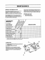
MAINTENANCE
SCHEDULE
FILL IN DATES
AS YOU COMPLETE
REGULARSERVICE
Check Engine Oil Level
SERVICE DATES
_
Change Engine Oil
_
,/
irlsPect Spark Arrester Muffler
Inspect Air Screen
Vf
Check and Clean AirCleaner
Replace Air Cleaner Cartridge
El
Clean Engine Cylinder Fins
t#/"
Replace Spark Plug
v"
Lubricate Spindles (2)
1 - Change more often when operiting unaer • heavy load or in'high climate temperatures,
2 - Service more often when operating In dirty or dusty conditions.
®
LUBRICATION
(_
REFER TO ENGINE MAINTENANCE SECTION OF
THIS MANUAL.
(_
GENERAL PURPOSE GREASE
IMPORTANT: Do not oil or grease pivot points.
Viscouslubricantswill attract dust and dirt that can
cause wear on pivot points. If you feel they must be
lubricated, use only a dry powderedgraphite type
lubricant.
®
15
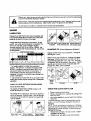
Disconnect spark plug wire before performing any maintenance (except carburetor adJuatmen'
to prevent accidental starting of engine.
Prevent f res v Keep the engine free of grass leaves sped oil or rue Remove fuel from tank
w
before tipping• unit _ for maintenance
Clean muffler area of all grass, dirt and debr e.
Do not touch hot muffler or cylinder fins as contacl may cause burns.
ENGINE
LUBRICATION
Change the oil after the first two hoursof operationand
every 25 hours there after or at least onco a year if the
mower Is not used for 25 hours in one year.
Change and add oil accordingto chart below. Do not
overfill. Use a high quality detergent oil classified"For
Service AF, SG, SH," such as Briggs& Stretton
'warranty certified" SAE 30 oil, Part No. 100005. Use
no special additives with recommended oils. Do not mix
oil with gasoline.
Grades
°F
_{)
I_C--OC,3O
,3O
0
_0
-2O
2_
.10
32
0
40
SO
10
2O
100
3_
ao
* Air cooled engines run hotter than automotive
engines. The use of mL ii-viscosityoil (such as 10W30, Etc.) in ambient temperatures above"40" F (4° C)
will result in higher than normal oil consumption. If
multi-viscosity bit is used, checkthe oil level more
frequentlyto prevent any possibleengine damage due
to lack of lubncetion.
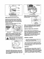
Fill to FULL mark If oil is required, add Tighten dipstick beon dipstick,
slowly. Recheck level, fore starting engine.
CHANGING
OIL (Follow Maintenance Schedule.)
Charv'jeoil after first 5 hours of operation. Change oil
while engine is warm.
Remove drain plug and drain oil. Replace and tighten
drain plug. Remove dipstick and refill with new oil of
recommended grade (see chart, page _.3A). Start ar_l
run engine at idle for 30 seconds. Stop engine. Walt 30
seconds and re-check bit level. If ,'_luired, add oil to
bring level to FULL mark on dipstick.
7/1
"_ Use of SAE 30 oil below 40" (4° C) will result in herd
starting and possibly engine damage due tO inadequate
lubdcetion.
Typical
drain
plugs
CHECK OIL LEVEL BEFORE STARTING ENGINE
OIL t3P, AIN
PLUG
TO
RE_4OVE
Oil drain
Oil fill
Add oil as shown below.
Oil capacity of Model Series 190000 is about 1-1/8
quarts(36 ounces or 1.1 liters).
After filing with or changingoil, start and run engine at
idle for 30 seconds, Shut off engine. Wait 30 seconds
and check oil level. Add oil if required,to bfiug to Full
mark on dipstick.
CHECK AND CLEAN AIR FILTER
•
•
Remove cover knob and cover.
Remove cartridge knob. Carefully lift cartridgefrom
base over stud..
•
clean base _
to prevent debrisfrom entering
carburetor.
To service cartridge, clean by tapping gently on aflat
surface. Do not oil cartridge. Replace if very dirty or
damaged.
NOTE: Do not use petroleum solvents, e.g., kerosene,
which will cause the cartridge to deteriorate. Do not use
pressudzed air.to clean cartridge. Pressurized air can
damage the cartridge.
•
Reassemble cartridge over stud on base. Tighten
certddge knob securely.
• Replace cover and tighten cover knob securely.
CLEAN
ALL DIRT
AREA OF
ANO DEBRtS
CARTRIDGE
Air cooJJng'system
BkSE
Replace spark plug. Do not blast clean. Clean by
scraping or wire brushingand washing with a
commercial solvent.
Dual element sir cleaner
KEEP
ENGINE
AND PARTS
CLEAN
030" (076 turn)
Do not clean with a forceful spray of water because
water could contaminate fuel system. With a brush or
cloth, remove grass, chaff or debris from finger guard
daily (more often if needed) to prevent engine damage
caused by overheating.
PART NO 491055
To assure smooth operation, keep governor linkage,
.springsand controlsfree of debris.
Spark plug
NOTE: In some areas, local law required using resistor
spark plug to suppress ignitionsignals. If this engine
was originally equipped with resistorspark plug, use
same type for replacement.
REMOVE
Finger guard
Linkage, springs & controls
GENERAL
_lk
DEPOSITS
Remove cylinder head every 100-300 hours of
operation. Scrape and wire brushcombustion deposits
from cylinder, cylinder head, top of piston and around
valves. Use a soft brush to remove depOsits.
Reassemble gasket and cylinder head• Turn screws
down finger tight. Torque cylinder head screws in a
staggered sequence to 165 in. Lb. (t9 Nm).
If engine muffler is equipped with a spark an'ester
screen, remove for cleaning and inapactJon.Replace if
damaged or plugged. See an suthodzed Bdggs &
Stratton Service Deater for correct replacement.
I'
COMBUSTIBLE
clean muffler area to remove all grass and
Daily °r m°re °fte'n' bef°re runningengine' I
combustibledebris
•
•
CLEANING
Clean engine, finished surfaces and wheels free of
gasoline, oil and all foreign matter.
Protect painted surfaces with automotive type wax.
We do not recommend usinga garden hose to clean
your unit unlessthe muffler, air filter and carburetor are
covered to keep water out. Water in engine can result
in a shortened engine life.
MUFFLER
CLEAN
Muffler and spark attester
Grass, chaff or debris may clog the air cooling system,
especially after a prolonged operation cutting tal!, dry
grass. Remove blower housingand cle_n area shownto
prevent overheating and engine damage. Clean more
often if necessary.
Do not operate mower without muffler. Do not tamper
with exhaust system. Damaged muffler or spark
an'ester could create a fire hazard, Inspect periodically.
and replace if necessary If your engine is equippedwith
a spark an_s_r screen assembly, remove every 50
hours for cleaning and inspection. Replace if damaged.
17
I
SERVICE
AND ADJUSTMENTS
I
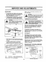
BLADE CARE
•
NOTE: Check nuts and blades occasionallyto make
sure nuts are tight.
For best resultsmower blades must be kept sharp.
the blades can be sharpenedwith a few strokes of a
file or on a grindingwheel. Do not attemptto
sharpen while blades are on mower.
•
I
To remove blade for sharpening, use wooden block
to hold blade while removing the blade mounting
nut. The nuts have right hand threads. (See Fig. 7)
Do not handle mower blades with bare
hands,
Careless or improper handling
CAUTION:
may result in serious injury,
4_11
Shut off mower engine and remove spark
plug
wire from spark plug before making
CAUTION:
any adjustments or repairs to mower.
CARBURETOR
ADJUSTMENTS
The manufacturer of the equipment on
which this engine is installedspecifiestop
speed at whichthe engine will be operated.
DO NOT EXCEED this speed.
I
Differences in fuel, temperature, altitude or load may
require
minor carburetor adjustment. Air Cleaner and
air cleaner cover must be assembledto carburetor
before starting engine.
The carburetor on this engine is low emission, it is
equipped with and idle mixture valve with a limiter (see
inset), which allows some adjustment, and an idle speed
edjustment screw.
ADJUSTMENTS
WOOD
BLOCK
BLADE
NUT---..-_
Start engine and warm up approximately 5 minutes
before adjusting. With engine running, place throttle
control in SLOW position. Rotate carburetor throttle
lever againstthe idle speed screw and hold it. Turn idle
speed screw to obtain 1750 rpm.
FIG. 7
•
•
When grinding,take care to maintain blade balance.
Check blade for properbalance before reinstalling
to mower.
To check and balance blade use a balancing
machine or fixture as shown in figure 8. File
material oft heavier end of blade until it is balanced.
,_,ON NAIL.
_REMA[N
-BENCH.
DO
NOT
LET BLADE
ALEVEL.
BALANCED
BLADE
TOUCH___
WILL
Rotate idle mixture valve full travel clockwiseand then
counter clockwise. Finally, positionidle mixture valve in
middle of travel. Check idle speed and re-adjust to
1750 rpm, if necessary.
Move throttle controlto FAST position, Engine should
accelerate smoothly. If it does not, adjustIdle mixture
valve countemlockwise1/8 turn.
-_"
I _._
CARBUR_OR
THF_O_LE
LEVER
IDLE MLXTURE
WITH
_
'\
WORKBENCH
NAiL
,WITH
LUBRICATED
DROP OF OIL
_DLE SPEEO
SCREW
FIG. 8
To a
sa[isfacto_¥ _=ration,we recommend that
you (_
,_dold ...ad .s _, d _eplace them with new ones
before the start of each mowing season.
18
Carburetor adjustments
VALVE
LiMITER
I
II
I
BELT REPLACEMENT
CLEANING
Disconnect'spark
plug wire from spark
CAUTION:
plug before replacing V-belt.
_lk
Water pressure from a garden hose will remove fresh
clippings from the underside of the mower. Clean
mower after each mowing.
DAILY
•
Move Blade Clutch Lever to the "DISENGAGED"
position.
Removetwo belt covers. (See Fig. 9)
Loosen three bolts and pivot belt guides away from
pulleys.
Move belt brake away from spindlepulleys, and
remove V-belt from aroundtwo spindle pulleys.
Remove V-belt from aroundengine pulley.
Disconnect small springfrom idler arm.
Grasp body of large idler spring and pull springto
the right side of mower until idler pulley is against
spindle pulley.
Remove V-belt from idler pulley.
Place new V-belt onto idler pulley and release large
springto allow idler to return to original position.
Reconnect small springto idler arm.
Assemble V-belt around engine pulley.
Move belt brake away from spindle pulley; then
assemble V-belt onto spindle pulleys.
P_ace Blade Clutch Lever into "ENGAGED" position.
Repositior_ three belt guides to odginal position with
approximately 1/16 inch clearance from pulleys and
retighten bolts to secure belt guides,
•
•
•
•
•
•
•
•
•
•
•
•
REPAIR PARTS
Your rotary mower has been produced with components
designed for your unit. Although standard V-Belts,
bearings, blades, pulleys, etc. may look like parts used
on your rotary mower, many are of a different
constructionand could in some cases cause the mower
to malfunction.
For continued satisfactory-performanceuse only repair
parts supplied by the manufacturer. See your Sears
Service Center for replacement parts.
I __
•
•
•
INNER
NUT
L_:<3SEN
OUTER
Reassemble two belt covers and return Blade Clutch
Lever to "DISENGAGED" position.
CHECKING
MAINTENANCE
Make sure all nuts and bolts are tight, cotter pins and
retainer spdngs are secure. Keep blades sharp.
Observe all safety precautions. Keep mower well
lubricated.
NOTE: Belt Guides should not touch V-belt or pulleys
when unit is in engaged position.
•
THE MOWER
_T{GHTEN
DRIVE TENSION
Remove V-belt cover from right side of unit.
Place Blade Control Lever in the"ENGAGED"
position.
Check tension springlength. It shouldbe 5-3/8" to
5-518"over the coils of the Spring Body. See Figure
9.
IDLER PULLEY
SPRING
EUDq.T
BOLT -
ADJUSTING DRIVE TENSION
To Increase Drive Spring Tension
•
•
Place blade clutch lever in the "DISENGAGED"
position.
Loosen the inner nut o_ the clutch cable.
•
Tighten the outer nut to increase spring tension.
NOTE: For every 1/8" adjustment made to the cable
yOU will get approximately
1/8" movement on the
tension spring.
To Decrease
•
NUT
Drive Spring
U',NDUE
Tension
•
Place blade clutch lever in the "DISENGAGED"
position.
Loosen the outer nut of the clutch cable.
•
Tighten the inner nut to decrease
spring tension.
FIG. 9
19
SERVICE
NOTES
I
i
DATE:
SERVICE:
DATE:
SERVICE:
DATE:
SERVICE:
DATE:
SERVICE:
DATE:
SERVICE:
DATE:
SERVICE:
DATE:
SERVICE:
bATE:
SERVICE:
bATE:
SERVICE:
bATE:
SERVICE:
DATE:
SERVICE:
DATE:
SERVICE:
2O
I
I
STORAGE
Immediately prepare your mower for storage at the end
of the season or ff the unitwill not he used for 30 days
or more.
CYLINDER
MOWER
•
•
•
When the mower is to be stored for a periodof time,
clean It thoroughly,remove all dirt, grease, leaves, etc.
Store in a clean dry area.
•
Clean entire mower. See "CLEANING" below.
•
Lubricate as shown in the maintenance section of
this manual.
•
Be sure that all nuts, bolts, screws, and p[ns are"
securely fastened. Inspect moving parts for
damage, breakage and wear. Replace if necessary.
• Touch up all rustedor chipped paint surfaces;sand
lightlybefore painting,
Remove spark plug.
Pour one ounce (29 ml) of oil through spark plug
hole into cylinder.
Pull starter handle slowly a few times to distribute
oil.
Install new spark plug.
•
OTHER
•
•
Do not store gasoline from one season to another.
Replace your gasoline can if your can startsto rust.
Rust and/or dirt in your gasoline will cause
problems.
If possible, store your unit indoorsand cover it to
give protectionfrom dust and dirt.
Cover your unit with a suitable protective cover that
does not retain moisture. Do not use plastic.
Plastic cannot breathe which causes condensation
to form that will rust your mower
•
•
CLEANING
mMPORTANT: =or best performance, keep Mower
Housing free of built-up grass and trash. Clean the
underside of your mower after each use.
•
•
•
CAUTION: Never cover mowerwhile
engine may
and ignite
exhaust
are stilla fire.
warm.
Cover
causing
CAUTION:
_L
Clean the underside of your mower by scrapingto
remove build-up of grass and trash.
Keep finished surfaces and wheels free of all
gasoline, oi!, etc.
Do not usea garden hose to clean mower.
ENGINE
•
_
from spark plug end place wire where it
cannot come in contact with the spark
CAUTION: Disconnect spark plug wire
plug.
I_IL
•
t
i
Never use engine or carburetor cleaner products in
the fuel tank or permanent damage may occur.
Use fresh fuel next season.
NOTE: Fuel stabilizer is an acceptable alternative in
minimizing the formation of fuel gum deposits during
storage, Add stabilizer to gasoline in fuel ta(_kor
storage container. Always follow the mix ratio found on
stabilizer container. Run engine at least 10 minutes
after adding stabilizer to allow the stabilizer to reach the
carburetor. Do not drain the gas tank and carburetor if
using fuel stabilizer.
ENGINE OIL
Drain oil when engine is shut off but stillwarm.
21
Never store the mower with
where fumes may reach an Open flame or
asoline ifi the tank inside a building
spark. Allow the engine to cool before
storing In any enclosure.
i
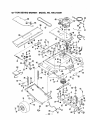
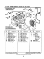
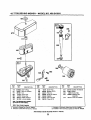
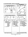
42" TOW BEHIND
MOWER
- MODEL
NO. 486.243291
0
58
89
91
47
57
39
21
67
,_
31
42" TOW
BEHIND
HA23834
HA23596
HA23343
HA446363"
43064*
HA23519
HA23516
HA23246
HA124634*
HA20129
HA23193
HA22951
HA2.3194
HA22987
HA120359
HA23518
43262*
HA2.2948
HA3430
44180
HA23196
HA23259
24.
25,
26.
27.
28.
29.
30,
31,
32.
33.
34.
35.
36.
37.
38.
39.
40.
41
42.
43,
44.
45.
46.
47,
48,
49.
50.
51.
52.
53,
54.
55,
56.
57.
58.
59.
60.
61.
62,
63.
64.
65.
88.
HA15015
1.
2.
3.
4.
5.
6.
7.
8.
9,
10.
11.
12.
13.
14.
15.
16.
17.
18.
19.
20.
21.
22.
l
Part No.
23,
Item
No.
HA8979
41676"
HA23197
43082*
HA17322
HA9411666*
43648"
HA4!19"
HA0293
24617
HA23253
HA23252
HA159920*
HA120217"
HA120361 *
HA23513
HA240t 0
HA23241
HA22994
HA115321 *
HA3073
HA17285
HA12315
HA22980
4300t *
HA19464
HA23836
HA23644
HA20986
HA3341
HA22759
HA23262
HA23647
HA23812
HA23597
HA23755
HA12t 38
HA126145"
HA120898*
43432*
HA12988
HA20710
HA23645
MOWER
- MODEL
Description
NO. 486.243291
_,/.
Req.
Item
No,
Mower Deck Pan ........................................
Part No.
Description
1
67.
HA23525
Hitch Tube ..................................................
Rod- Deflector Mounting ............................ 1
68.
HA15683
Self Tapping Screw ....................................
Pulley .......................................................... 2
69,
HA12314
Danger Decal ............................................
Washer, 3/8" x 7/8' x .08". ......................... 3
70.
HA22996
Left Hand Wheel Mounting Bracket ..........
Nut- 5/16-18 Hex Lock .............................. 4
71.
HA22997
Right Hand Wheel Mounting Bracket .......
Hitch Assembly ........................................... 1
72.
HA103407
Cotter Pin ...................................................
Mower Bade
......................................
2
73,
HA23638
Clevis Pin ...................................................
Salleville Washer ........................................ 2
74.
HA24350
Wheel .........................................................
Nut, 9/16-15 Hax ........................................ 4
75.
HA456151
FJat Washer, 13/ t S" x 1-1/2"x .134' .........
Flat Washer ................................................ 2
76,
HA2.3263
Flat Washer ...............................................
Screw, 3/8-16 x 1-1/4 Thread Forming ..,. 25
77.
HA23229
Hub Cap .....................................................
Belt Guide ................................................... 3
78.
HA23646
Height Adjustment Strap ...........................
Brake Spr ng Assembly ............................. 2
79,
44101*
Cotter Pin, 3/32" x 3/4". .............................
Brake Rod ...................................................
1
80.
HA24441
Strap, L_ch ...............................................
Washer, 1/2" x I-1/4" x .08'3 ..................... 2
81.
HA20186
Spring, Latch ...................................... ...,...
C_utchSeltcrank ......................................... I
82.
HA23760
Clip - Hose/Cable 1/2" ...............................
Nut, 1/2-13 Hex Lock ................................. 6
93.
HA23761
Clip - Hose/Cable 3/8". ..............................
Brake Release Rod .................................... 1
84.
HA23527
Lever. Clutch ............................................
Hair Cotter Pin ............................................ 5
85,
HA15200
Washer, 13/32" x 1-3/16" x 3/16 °, .............
Bolt, 5/16.18 x 2" Hex Head Grade 5 ........ 3
96.
43062*
Bolt, 3/8-°16 x 1-1J2" Hex Head .................
Idler Tension Spring ................................... 1
97.
HA19445
Spring ........................................................
Idler Bracket ............................................... 1
89.
HA120368"
Nut, 5/15-24 Hex .......................................
Idler Pu ey ...........................
1
90.
43012*
Bolt, 1/4-20 x 3/4' Hex Head ....................
Flat Washer ................................................ 5
91.
HA23532
Wire ............................................................
Bolt, 3/8-16 x 1-3/4 =Hex Head .................. 1
92,
HA23586
Operator's Presence Seat .........................
Interlock Bracket......................................... 1
93.
HAl1947
Cord Clip ....................................................
Nut, 3/8-16 Hex Lock ................................. 4
94.
43088
Washer, 1/4" Std .......................................
Interlock Swffch .......................................... 1
99,
47707
Grip - Handle .............................................
Screw, #10-16 x 1/2" Serf Tappin 9 ............. 8
96.
HA181666.
Bolt, 7/18-20 x 1-1/4' Hex Head ...............
Bolt, 1/4-20 x 1-1/2" Hex Head .................. 1
97.
HA4143
Washer, l"x 13/16" Thick .........................
Nut, 1/4-20 Hex Lock ................................. 4
98.
43601
Washer, 1.59" x 1,032" x .06" ...................
Extension Spring ........................................ I
99,
HA120389
Washer, 1/2 =x 1-1/4" x ,083". ...................
Clutch Cable ............................................... 1
NP
HA24059
Manual - Operator's
Module ConneCtor ...................................... 1
Modu e
.........................................
1
Screw, #10-24 x 1/2" Pan Head ................. 2
*Standard Hardware - Purchased Locally.
Washer, #10 Med. Lock ............................. 2
Nut, #10-24 Hex ......................................... 2
Engine Mountfng Plate ............................... I
8 HP Engine ............................................... 1
SpJtldle Assembly
................................. 2
Pulley ..........................................................
1
Set Screw, 5/16-18 x 5/16" Socket Hd....... 2
Square Key ................................................. 1
Danger Decal .............................................
2
Danger Decal .............................................
2
V-Belt .......................................................... 1
Bolt, 3/6-16 x 1" Hex Head ........................ I
Rubber Grommet ........................................ 1
Clays Pn
..............................
2
Towbar Assembly ....................................... 1
Hitch Pin .....................................................
1
Hair Cotter Pin ............................................ 1
On/Off Switch ............................................. 1
Decal- Engine Shu Off
...................... 1
Clutch Lever Decal ..................................... 1
Wire Harness .............................................. 1
Deflector ..................................................... 1
Decal - Operation ....................................... 1
Mower Roller .............................................. 1
Bolt, 1/2-13 x 7" Hex Head ....................... 1
Washer, 9/16" Lock .................................... 2
Bolt, 3/8-18 x 2-1/2" Hex Head .................. 4
Deflector Spring ......................................... I
Sears Logo Decal ....................................... 1
Salt Cover .....: ............................................. 2
23
Qty.
Req.
1
6
1
1
1
8
2
2
2
2
2
2
1
2
2
6
3
1
2
1
1
4
2
1
1
2
4
2
1
2
1
3
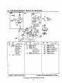
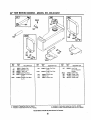
42" TOW BEHIND MOWER - MODEL NO. 486.243291
I
j5
•
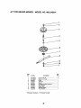
Item
No.
1.
2.
3.
4.
5.
6,
7.
8,
9,
10.
Part NO.
HA124634*
HA120898"
HA23343
HA23243
HA23244
HA23242
HA23245
HA23516
HA23246
HA20129
*Standard
Hardwar9
i
8
Description
Qty,
Req.
Nut, 9/16-18 Hex ....................................... 2
Washer, 9/16 Lock.................................... 1
Pulley ......................................................... 1
Jacksheft .................................................... 1
Spacer ....................................................... 1
Housing & Searing Assembly ................... 1
Blade Adapter ............................................ 1
Mower Blade .............................................. 1
Belleville
Washer .......................................
I
ThrustWasher ...........................................
I
- Purchased
24
Locally
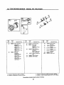
42" TOW BEHIND
MOWER
- MODEL
NO. 486.243291
l_r REQUIRES SPECIAL TOOLS
TO INSTALL. SEE REPAIR
INSTRUCTION MANUAL
230 _)
3
635_
mm
¸
10_
562
11019 LABEL KIT I
13J
11058
OWNER'S
"ANUALI
.REF.
NO,
PART
NO.
1
2
3
495623
495657
*391086
5
214015
7 _Z'-272163
8
495735
9 _,_27803
10
94621
11
280005
13
94565
13A
94926
14
94622
REF.
NO.
DESCRIPTION
Cylinder
Bushing
Seal-Oil
227
230
306
307
308
337
383
552
562
592
614
616
635
Assembly
Head--Cylinder
Gasket-Cylinder
Head
Breather Assembly
Gasket-Breather
Screw-Hex.
Tube-Breather
Screw-Hex.
Stud-Hex.
Ddve
Screw-Hex.
(3" Long)
PART
NO.
DESCRIPTION
493935
94927
496797
94930
224896
802592
89838
491986
94907
231978
93306
495157
66538
Lever-Governor
Washer-Lever
Shield-Cylinder
Screw-Hex.
Cover-.Cylinder
Plug--Spark
Wrench-Spark Plug
Bushing-Gov. Crank
Bolt-Governor Lever
Nut-Hex.
Pin-Cotter
Crank--Governor
Boot-Spark Plug
* Included in Gasket Set-Part No. 299577.
• Includedin Carburetor Kit-Part No. 497535.
Assemblies
13,
REF.
NO.
869
870
871
1019
1058
PART
NO.
DESCRIPTION
211661 Seat-Valve
(Intake)
262924 Seat-Valve
(Exhaust)
261961 Bushing--Guide
(Exhaust Valve)
Note
231218 BushingGuide
(Intake Valve)
491182 Label Kit
273861 Owner's Manual
4. Included in Carburetor Gasket Set-Part No. 494385.
O Included in Valve Overhaul Gasket Set-Part No, 498536.
include all parts shown
25
in frames,
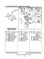
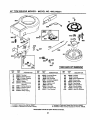
4_2"TOW
BEHIND
MOWER
- MODEL
NO. 486.243291_
741 _--_
REE
NO.
PART
NO.
4
12
392548
*271701
759
RE,=.
NO.
DESCRIPTION
Sump-Er':gine
Gasket-,Srankcase
(.015" Thick)
*27876 GasketCrankcase
(.005* Thick)
*27877 GasketCrankcase
15
*
•
94239
(,009" Thick)
Plug-Oil Drain
Included in Gasket Set-Part No. 299577.
Inctuded in Carburetor Kit-Part No. 497535.
PART
NO.
16
495629
19
20
22
295963
*391086
93585
24
43
222698
491397
DESCRIPTION
Crankshaft
Bushing
Seal-Oil
Screw-Hex,
Note -94690 Screw-Hex,
(Used in Pos. No. 1)
Key-Flywheel
Governor_il
Slinger
REE
NO.
PART
NO.
DESCRIPTION
46
211689
Gear-Cam
146
741
767
758
759
761
1020
1021
94388
263025
213996
390172
298909
94592
261190
94160
Key-Timing
Gear-Timing
Link-Counterweight
Counterweight
Pin-Counterweight
Screw-Hex
Eccentric
Pin-.Groove
_. Included in Carburetor
Gasket Set-Part No. 494385.
O Included in Valve Overhaul Gasket Set-Part No. 498536.
Assemblies include all parts shown in frames.
42" TOW
BEHIND
MOWER
- MODEL
NO. 486.243291
45
868
I
34
4O
_
_
35
!J
REF.
NO.
PART
NO.
25
499907
REF.
NO,
DESCRIPTION
Piston Assembly
(Standard)
499908 Piston Assy.
(.010" O.S.)
499909 Piston Assy.
27
28
(.020"O.S,)
29
PART
NO.
263161
499911
390462
499910 Piston Assy.
(.030"O.S.)
26
499921
Ring Set
(Standard)
391670 Ring Set
(.010" O.S.)
391671 Ring Set
(.020" O.S.)
391672 Ring Set
(.030" O.S.)
32
94670
33
390420
34
261055
DESCRiPTiON
Lock-Piston Pin
Pin-Piston
(Standard)
499920 Pin-Piston
(.005" O.S.)
Rod-:-Connecting
(Standard)
390773 Rod-Conn.
(.020" Undersize)
Screw-Connecting
Rod
Valve-Exhaust
Valve-Intake
* Included in Gasket Set-Part No. 299577.
Included in Carburetor Kit-Part No. 497535.
Assemblies
REF.
NO.
35
36
40
41
45
868
PART
NO.
DESCRIPTION
26828 Spr_ng-Valve
(Exhaust)
65906 Spring--Valve
(Intake)
221596 Retainer-Valve
(Intake)
292260 Retainer-Valve
(Exhaust)
260933 Tappet
497656 Seal-Valve
, Included in Carburetor Gasket Set-Part No. 494385.
O Included in Valve Overhaul Gasket Set-Part No. 498536.
include all parts shown in frames.
27
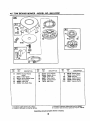
42" TOW BEHIND
MOWER
- MODEL
NO. 486.243291,
5O
950_
"k" REQUIRES SPECIAL TOOLS
TO INSTALL. SEE REPAIR
INSTRUCTION MANUAL.
REF.
NO.
PART
NO.
50
213819
51 h272465
51A _-_272554
*
•
53
93
95
94637
281346
e94098
98
104
105
106
108
495800
=231759
e231855
e231854
224559
REF.
NO,
DESCRIPTION
PART
NO.
DESCRIPTION
Manifold-Intake
Gasket-Intake
Gasket-Intake
111
123
262715
94913
Spring-Friction
Screw-Torx'_
125
692684
Carburetor
Stud-Carb. Mounting
Bushing-Throttle
Shaft
Screw-Round
Head
127
Screw-Idle Speed
Pin-Roar Hinge
Valve-Needle
Seat-Inlet
Valve-Choke
•
142
139
224668
131
494885
133
494381
137 e•281165
138 e,_281164
141
495097
Washer
Shaft-Choke
Assemblies
•
690121
DESCRIPTION
Nozzle-Carburetor
(Standard)
692688 Nozzle-Carb.
186
493496
634
950
965
975
987
e494453
94642
94010
495933
,281166
(High Altitude)
Connector-Hose
Seal-Spring Assembl
Screw-Bowl Mounting
Nut-Hex.
Bowl-Float
Seal-Throttle Shaft
Included in Carburetor Gasket Set-Part No. 494385.
Included in Valve Overhaul Gasket Set-Part No. 498536.
include all parts shown in frames.
28
PART
NO.
Hex.
Plug-Welch
(Sold in Kit Only)
Valve-Throttle
Shaft-Throttle
Float-Carburetor
Gasket-Float
Bowl
Included in L=asket Set-Part No. 299577.
Included in Carburetor Kit-Part No. 497535.
REF.
NO.
42" TOW
BEHIND
MOWER
- MODEL
NO. 486.243291
467
346
171
524_
j 683
REF.
NO.
PART
NO.
116
161
171
224
284
300
302
*270920
494827
281051
94730
94704
393010
261409
DESCRIPTION
REF.
NO.
346
422
445
467
523
524
525
Seal-O-Ring
Base-Air Cleaner
Nut.
Screw-Hex.
Screw-Hex.
Muffler-Exhaust
Locknut-Muffler
PART
NO.
94874
223394
493910
493903
391840
*281370
280133
DESCRIPTION
Screw-Hex.
Bracket--Oil Fill
Filter-Air
Knob-Air Cleaner
Dipstick
Seal-Fill Tube
Tube-Oil Fitl
REF,
NO.
537
646
663
847
872
PART
NO._
DESCRIPTION
,_281106
224614
94929
392066
Gasket-Air Cleaner
Brace
Screw-Hex.
DipsticWTube
Assembly
281105 Cover-Air Cleaner
w,=feco,,,,,,_
p=t _-,=quid.
byIo=dI_,, Inmine lecalem.
3_eS4t,S_*/re=or/_muy
Includedin GasketSet-Part No. 299577.
Includedin CarburetorKit-Part No.497535.
• Included in Carburetor Gasket Set-Part No, 494385,
O Included in Valve Overbaul Gasket Set-Part No. 498536.
Assemblies include all parts shown in frames.
29
42" TOW BEHIND
MOWER
- MODEL
NO. 486.243291
284A
725
188
185
169 184_
REF.
NO.
PART
NO.
6
169
180
181
182
22963
90832
390225
493988
225074
Washer-Flat
Washer-Lock
Tank-Fuel
Cap-Fuel Tank
Sracket.-Fuel Tank
224884
(R,H,)
Bracket-Fuel
182A
REF.
NO.
DESCRIPTION
Tank
PART
NO.
DESCRIPTION
183
496853
183A
390405
184
94296
Strap-Fuel Tank
(R.H.)
Strap-PuaITank
(L.H,)
Screw-Hex.
185
184
90970
94627
Nut
Screw-Hex,
REF.
NO.
187
PART
NO.
296004
284A
94602
527
601
725
221429
95162
222175
DESCRIPTION
Line-Fuel
(Cut to Required
Length)
Screw-Hex.
Clamp-Tube
Clamp-Hose
Shield-Heat
(L.H.)
* Included in Casket Set-Part No. 299577.
e Included in Carburetor Kit-Part No. 497535.
Assemblies
_. Included in Carburetor
Gasket Set-Pad No. 494385.
_ Included in Valve Overhaul Gasket Set-Part No, 498536.
include
all parts
3O
shown
in frames.
42" TOW
BEHIND
MOWER
- MODEL
NO. 486.243291
3O4
305 _
334
265
232
222
354
[ 1036 LABEL KIT-EMISSION
RER
NO.
PART
NO.
23
37
73
74
75
202
298260
222475
224874
94680
225136
262769
209
222
232
265
260971
495611,
262787
221535
REF.
NO,
DESCRIPTION
Flywheel
Guard-Rywheel
Screen-Rotating
Screw-Hex,
Washer
Link-Mechanical
Governor
Spring-Governor
Bracket-Control
Spring-Link
Clamp-Casing
304
305
332
333
334
353
354
356
363
455
PART
NO.
496832
94786
92284
398811
94731
92791
90576
399223
19165
222561
DEscRIPTION
Housing-Blower
Screw-Hex.
Nut-Flywheel
Armature-Magneto
Screw-Hax.
Washer-Lock
Nut-Hex.
Wire-Stop
Flywheel Puller
Cup-Flywheel
* Included in Gasket Set-Pad No. 299577
• Included in Carburetor Kit-Part No. 49753_.
Assemblies
REF.
NO.
507
520
657
663
687
688
689
690
851
1036
PART
NO,
398525
93722
94906
94929
390701
221766
260847
90746
493880
499355
[
DESCRIPTION
Insulator
Terminal
Screw-Slotted Hex.
Screw-Hex.
Slide-Control
Cap-Spring
Spring-Friction
Screw-Slotted
Terminal-Cable
Label Kit-Emission
• Included in Carburetor Gasket Set-Part No. 494385.
Included in Valve Overhaul Gasket Set-Pad No. 498536.
Include all parts shown in frames.
31
42" TOW
BEHIND
608
655
REE
NO.
55
56
57
58
59
60
*
•
MOWER
- MODEL
NO. 486.243291
_
1016
PART
NO.
_
_
REE
NO.
DESCRIPTION
393576 Housing-Rewind
Starter
295871 Pulley,-Starter
490179 Spring-Rewind Starter
66094 Rope--Starter
490653 Insert-,Grip
490652 Grip-Starter Rope
"
"
PART
NO.
DESCRIPTION
REE
NO.
PART
NO.
DESCRIPTION
63
64
65
66
260414
230543
94904
399671
Spring-Ratchet
Adapter-Spring
Screw-Hex
Clutch-Starter
70
71
373
608
298799
394506
94908
390391
Ratchet-Clutch
Cover-Ratchet
Nut-Hex.
Starter-Rewind
67
68
394807
63770
Housing-Clutch
Bait--Clutch
655
1016
222598
490817
Anchor-Spring
Spacer-Rewind
Included in Gasket Set-Part No. 299577.
included in Carburetor Kit-Part No. 497535.
*, Included in Carburetor Gasket Set-part No. 494385.
_ Included in Valve Overhaul Gasket Set-Part No. 498536.
Assemblies include all parts shown in frames.
32
42" TOW
BEHIND
MOWER
- MODEL
NO. 486.243291
iii
358 GASKET SET
121 CARBURETOR
OVERHAUL
KIT
3_
127_
138 _
106(_
987_
20_
116_'
95_
537_
137_
_
634_.._
524_)
104_
51A_
51_
1os
1095 VALVE OVERHAUL
GASKET SET
137 0
I
REF.
NO,
PART
NO.
3 *391086
70*272163
9 O.27803
12 *271701
20
*391086
REF.
NO.
DESCRIPTION
Seal-Oil
Gasket--Cylinder Head
Gasket-Breather
Gasket-Crankcase
(.015" Thick)
*27676 GaaketCrankcase
(.005"
Thick)
*27877 GasketCrankcase
(.009" Thick)
Seal-Oil
PART
NO.
977 CARBURETOR
51
DESCRIPTION
51 e,_272465
51A _.272554
95
e94098
104 e231789
105 1231855
106 o231854
116 *270920
121
497535
127 •
Gasket-Intake
Gasket-Intake
Screw-Round Head
Pin-Roat Hinge
Valve--Needle
Seat-Inlet
Seal-Valve
Carburetor Kit
Plug--Welch
(Sold in Kit Only)
137 e_,281165 Gasket-Float Bowl
* Included in Gasket Set-Part No. 299577.
• Included in CarburetorKit-Part No. 497535.
Assemblies
REF.
NO.
GASKET SET
PART
NO,
135
DESCRIPTION
138 e.261164
142 e494877
358
299577
524 .281370
537 .261106
634 e494453
977
494365
987
1095
washer
Nozzl_uretor
Gasket Set
SeaJ-FillTube
Gasket-Air Cleaner
Seal-Spring Assembl,
Gasket SetCarburetor
*261166 Seal-Threttle Shaft
"498536 GasketSet-Valve
Overhaul
Included in Carburetor Gasket Set-Part No. 494385.
Included in Valve Overhaul Gasket Sat-Part No. 498536.
Include all parts shown in frames,
33
34
35
For the repair or replacement parts you need
delivered directly to your home
Call 7 am - 7 pro, 7 days a week
1-800-366-PART
(1-800-366-7278)
For in-homemajor brand repair service
Call 24 hours a day, 7 days a week
1-800-4-REPAIR
(1-800-473-7247)
F_)rthe locationof a
SearsPartsandRepairCenterin yourarea
Ca',',24 hours a day, 7 days a week
1-800-488-1222
|iN|BI
mmmmmmj
For informationon purchasinga Sears
Maintenance Agreementor to inquire
about an existingAgreement
call 9 am - 5 pm, Monday-Saturday
1-800-827-6655
SEARS
America'sRepair Specla#sts
FORM NO. HA24059 (REV. 2/00)