1
OCT04A-1.qxp
04.9.29 9:14 AM
Page 1
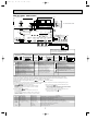
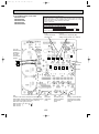
SPLIT-TYPE, HEAT PUMP AIR CONDITIONERS
SERVICE TECHNICAL GUIDE R410A
<Indoor unit>
[Model names]
PLA-RP·AA
PKA-RP·GAL
PKA-RP·FAL
PCA-RP·GA
PEA-RP·EA
PEAD-RP·EA
PEAD-RP·GA
<Outdoor unit>
[Model names]
PUHZ-RP·VHA
No. OCT04
REVISED EDITION-A
[Service Ref.]
PLA-RP·AA
PLA-RP·AA1
PLA-RP·AA.UK
PLA-RP·AA1.UK
PKA-RP·GAL
PKA-RP·FAL
PCA-RP·GA
PEA-RP·EA.TH-A
PEAD-RP·EA.UK
PEAD-RP·EA1.UK
PEAD-RP·GA.UK
Revision:
• PKA-RP•GAL, PKA-RP•FAL,
PCA-RP•GA, PEAD-RP•GA,
PUHZ-RP•VHA1 and
PUHZ-RP•VHA1-A are added in
REVISED EDITION-A.
• Please void OCT04.
[Service Ref.]
PUHZ-RP·VHA
PUHZ-RP·VHA1
PUHZ-RP·VHA-A
PUHZ-RP·VHA1-A
CONTENTS
1. PAIRING TABLE OF THE INDOOR AND OUTDOOR UNIT ·····2
2. SPECIFICATIONS FOR ELECTRICAL WORK ·························3
3. WIRING DIAGRAM·····································································6
4. REFRIGERANT SYSTEM DIAGRAM ······································15
5. HOW TO CHECK THE PARTS ················································24
6. MICROPROCESSOR CONTROL·············································33
7. INDOOR UNIT CONTROL························································39
8. OUTDOOR UNIT CONTROL····················································47
9. DIP SWITCH FUNCTION ·························································63
10. FUNCTION SETTING ·······························································76
11. TEST RUN • REPLACEMENT OPERATION
& EMERGENCY OPERATION···················································86
12. SELF-DIAGNOSIS ····································································92
13. TEST POINT DIAGRAM ·························································118
14. TROUBLESHOOTING ····························································127
15. SYSTEM CONTROL ·······························································131
OCT04A-1.qxp
1
04.9.29 9:14 AM
Page 2
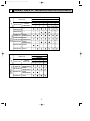
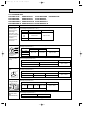
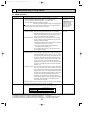
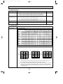
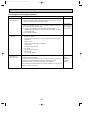
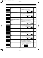
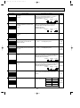
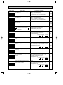
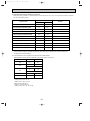
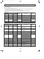
PAIRING TABLE OF THE INDOOR AND OUTDOOR UNITS
Outdoor unit
Heat pump type
Indoor unit
Heat pump
without
electric heater
Service Ref.
Service
Manual No.
PEAD-RP·EA.UK
PEAD-RP·EA1.UK
—
PEAD-RP·GA.UK
—
PLA-RP·AA
PLA-RP·AA1
1.6
2.5
VHA
VHA
VHA
VHA
VHA
5
6
VHA
VHA
VHA1 VHA1 VHA1
—
—
—
—
—
—
—
—
—
—
OC293
REVISED EDITION-B
PLA-RP·AA.UK OC297
PLA-RP·AA1.UK REVISED EDITION-C
PKA-RP·FAL
OC301
REVISED EDITION-A
PKA-RP·GAL OC305
PCA-RP·GA
OC311
—
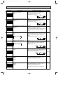
Service Ref.
PLA-RP·AA
PLA-RP·AA1
Service
Manual No.
—
—
Outdoor unit
Heat pump type
Indoor unit
Heat pump
without
electric heater
PUHZ-RP
4
3
2
3
VHA-A
PUHZ-RP
4
5
6
VHA-A VHA-A VHA-A
VHA1-A VHA1-A VHA1-A
OC293
REVISED EDITION-B
OC299
PEA-RP·EA.TH-A REVISED EDITION-A
PKA-RP·FAL
OC301
REVISED EDITION-A
PCA-RP·GA
OC311
—
2
—
—
OCT04A-1.qxp
04.9.29 9:14 AM
2
Page 3
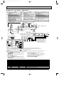
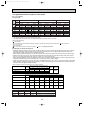
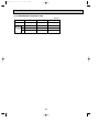
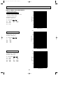
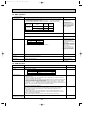
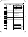
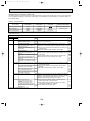
SPECIFICATIONS FOR ELECTRICAL WORK
2-1. Field electrical wiring(power wiring specifications)
PUHZ-RP•VHA
PUHZ-RP•VHA-A
Indoor unit model
RP1.6, 2V
RP2.5, 3V
RP4, 5V
~ / N (Single) 50Hz,
220-230-240V
Outdoor unit power supply
Wiring
Wire No. o size (mm2)
Outdoor unit input capacity
Main switch (Breaker)
*1
16A
25A
32A
40A
Outdoor unit power supply
2 o Min. 1.5
2 o Min. 2.5
2 o Min. 4
2 o Min. 6
Outdoor unit power supply earth
1 o Min. 1.5
1 o Min. 2.5
1 o Min. 4
1 o Min. 6
1 o Min. 2.5
1 o Min. 2.5
Indoor unit - Outdoor unit
*2
Indoor unit - Outdoor unit earth
3 o 2.5 (polar)
1 o Min. 2.5
1 o Min. 2.5
*3
Remote controller - Indoor unit
2 o 0.69 (Non-polar)
*4
Outdoor unit L-N
Circuit
rating
RP6V
AC 220-230-240V
*4
Indoor unit-Outdoor unit S1-S2
AC220-230-240V
*4
Indoor unit-Outdoor unit S2-S3
DC24V
*4
Remote controller - Indoor unit
DC14V
*1 A breaker with at least 3mm contact separation in each poles shall be provided.
Use non-fuse breaker (NF) or earth leakage breaker (NV).
*2 Max. 50m Total Max, including all indoor/ indoor connection is 80m.
*3 10m wire is attached in the remote controller accessory.
*4 The figures are NOT always against the ground.
S3 terminal has DC24V against S2 terminal. However, between S3 and S1, these terminals are NOT electrically insulated
by the transformer or other device.
Notes: 1. Wiring size must comply with the applicable local and national code.
2. Power supply cords and indoor/ Outdoor unit connecting cords shall not be lighter than polychloroprene
sheathed flexible cord. (design 254 IEC 57)
3. Install an earth longer and thicker than other cables.
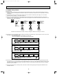
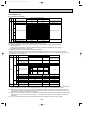
1:1 system
Synchronized twin and triple system Electrical wiring
• Synchronized twin
Outdoor
unit
Unit
power
supply
L
N
Grounding
S1
S2
S3
Indoor/outdoor
unit connection
cable
Outdoor
unit
Indoor
unit
1
2
Remote
controller
L
N
Unit
power
supply
S1
S2
S3
S1
S2
S3
Grounding
Indoor/outdoor
unit connection
cable
Indoor
unit
1
2
Indoor
unit
1
2
Remote
controller
S1
S2
S3
S1
S2
S3
• Synchronized triple
Outdoor
unit
Unit
power
supply
1
2
L
N
Grounding
3
Indoor
unit
S1
S2
S3
Indoor/outdoor
connection cable
S1
S2
S3
Remote
controller
Indoor
unit
Indoor
unit
1
2
1
2
S1
S2
S3
S1
S2
S3
OCT04A-1.qxp
04.9.29 9:14 AM
Page 4
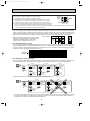
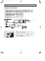
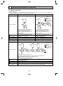
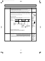
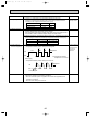
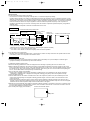
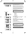
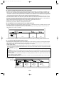
2-2. M-NET wiring method
(Points to notice)
(1) Outside the unit, transmission wires should stay away from electric wires in order to prevent electromagnetic noise from
making an influence on the signal communication. Place them at intervals of more than 5cm. Do not put them in the same
conduit tube.
(2) Terminal block (TB7) for transmission wires should never be connected to 220~240V power supply. If it is connected,
electronic parts on M-NET p.c. board may be burn out.
2
(3) Use 2-core x 1.25mm shield wire (CVVS, CPEVS) for the transmission wire. Transmission signals may not be sent or
received normally if different types of transmission wires are put together in the same multi-conductor cable. Never do this
because this may cause a malfunction.
Refrigerant
address 00
M-NET
address 01
Group
remote
controller
Power
supply
unit for
transmission
wire
Refrigerant
address 00
M-NET
address 02
A-control
remote
controller
A-control
remote
controller
Refrigerant
address 00
M-NET
address 03
A-control
remote
controller
It would be ok if M-NET wire (non-polar, 2-cores) is arranged in addition to the wiring for A-control.
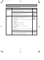
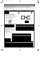
(4) Ground only one of any appliances through M-NET transmission wire (shield wire). Communication error may occur due to
the influence of electromagnetic noise.
“Ed” error will appear on the LED display of outdoor unit.
“0403” error will appear on the central-control remote controller.
✕ Bad example (Multi spot grounding of shield wire)
Central
remote
controller
Power
supply
appliance
M-NET type
outdoor unit
M-NET type
outdoor unit
M-NET type
outdoor unit
M-NET transmission wire
Good example 1 (Single spot grounding of shield wire)
Central
remote
controller
Power
supply
appliance
M-NET type
outdoor unit
M-NET type
outdoor unit
M-NET type
outdoor unit
M-NET transmission wire
Good example 2 (Single spot grounding of shield wire)
Central
remote
controller
Power
supply
appliance
M-NET type
outdoor unit
M-NET type
outdoor unit
M-NET type
outdoor unit
M-NET transmission wire
If there are more than two grounding spots on the shield wire, noise may enter into the shield wire because the ground wire
and shield wire form one circuit and the electric potential difference occurs due to the impedance difference among grounding spots. In case of single spot grounding, noise does not enter into the shield wire because the ground wire and shield
wire do not form one circuit.
To avoid communication errors caused by noise, make sure to observe the single spot grounding method described in the
installation manual.
4
OCT04A-1.qxp
04.9.29 9:14 AM
Page 5
● M-NET wiring
2
M-NET
(1) Use 2-core x 1.25mm shield wire for electric wires.
terminal
Ground
(Excluding the case connecting to system controller.)
block
wire
(2) Connect the wire to the M-NET terminal block.Connect one core of the
transmission wire (non-polar) to A terminal and the other to B. Peel the
A B S
shield wire, twist the shield part to a string and connect it to S terminal.
Transmission Shield
(3) In the system which several outdoor units are being connected, the terminal
wire part
(A, B, S) on M-NET terminal block should be individually wired to the other
outdoor unit’s terminal, i.e. A to A, B to B and S to S.In this case, choose one of those outdoor units and drive a screw
to fix an ground wire on the plate as shown on the right figure.
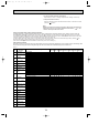
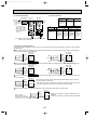
2-2-1. M-NET address setting
In A-control models, M-NET address and refrigerant address should be set only for the outdoor unit. Similar to Free Combo
system, there is no need to set the address of outdoor unit and remote controller. To construct a central control system, the
setting of M-NET address should be conducted only upon the outdoor unit. The setting range should be 1 to 50 (the same as
that of the indoor unit in Free Combo system), and the address number should be consecutively set in a same group.
23
901
23
901
901
901
78
901
~
45 6
45 6
23
45 6
23
tens
digit
78
78
setting SW12
78
901
50
23
45 6
2
23
45 6
1
45 6
SW11
ones
Switng digit
78
<Setting example> M-NET Address No.
Address number can be set by using rotary switches
(SW11 for ones digit and SW12 for tens digit), which
is located on the M-NET board of outdoor unit.
(Factory setting: all addresses are set to “0”.)
78
2-2-2. Refrigerant address setting
In case of multiple grouping system (multiple refrigerant circuits in one group), indoor units should be connected by remote
controller wiring (TB5) and the refrigerant address needs to be set. Leave the refrigerant addresses to “00” if the group setting is not conducted. Set the refrigerant address by using DIP SW1-3 to -6 on the outdoor controller board. [Factory setting:
all switches are OFF. (All refrigerant addresses are “00”.)]
ON
ON
OFF
Refuigrant
address
ON
OFF
1 2 3 4 5 6
0
ON
1 2 3 4 5 6
ON
9
10
ON
11
7
ON
OFF
1 2 3 4 5 6
12
13
1 2 3 4 5 6
6
ON
OFF
1 2 3 4 5 6
OFF
1 2 3 4 5 6
5
OFF
1 2 3 4 5 6
ON
OFF
1 2 3 4 5 6
4
ON
OFF
1 2 3 4 5 6
ON
OFF
1 2 3 4 5 6
3
OFF
1 2 3 4 5 6
8
ON
OFF
1 2 3 4 5 6
2
ON
OFF
OFF
ON
OFF
1 2 3 4 5 6
1
ON
ON
OFF
1 2 3 4 5 6
OFF
1 2 3 4 5 6
1 2 3 4 5 6
14
15
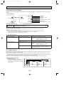
2-2-3. Regulations in address settings
In case of multiple grouping system, M-NET and refrigerant address settings should be done as explained in the above section. Set the lowest number in the group for the outdoor unit whose refrigerant address is “00” as its M-NET address.
Group A
System
controller
Power
supply
unit for
transmission
wire
Group B
Refrigerant
address 00
M-NET
address 01
Group C
Refrigerant
address 00
M-NET
address 02
Refrigerant
address 01
M-NET
address 03
Refrigerant
address 00
M-NET
address 04
TB5
A-control
remote
controller
A-control
remote
controller
A-control
remote
controller
w Refrigerant addresses can be overlapped if they are in the different group.
Group A
System
controller
Power
supply
unit for
transmission
wire
Refrigerant
address 00
M-NET
address 01
Group B
Refrigerant
address 01
M-NET
address 02
Refrigerant
address 00
M-NET
address 04
Refrigerant
address 01
M-NET
address 03
Refrigerant
address 02
M-NET
address 05
TB5
A-control
remote
controller
A-control
remote
controller
w In group B, M-NET address of the outdoor unit whose refrigerant address is “00” is not set to the minimum in the group. As
“3” is right for this situation, the setting is wrong. Taking group A as a good sample, set the minimum M-NET address in
the group for the outdoor unit whose refrigerant address is “00”.
5
OCT04A-1.qxp
04.9.29 9:14 AM
3
Page 6
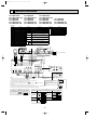
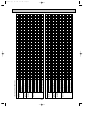
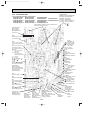
WIRING DIAGRAM
PLA-RP1.6AA
PLA-RP1.6AA.UK
PLA-RP3AA
PLA-RP3AA1
PLA-RP3AA.UK
PLA-RP3AA1.UK
PLA-RP2AA
PLA-RP2AA.UK
PLA-RP4AA
PLA-RP4AA1
PLA-RP4AA.UK
PLA-RP4AA1.UK
PLA-RP2.5AA
PLA-RP2.5AA.UK
PLA-RP5AA
PLA-RP5AA1
PLA-RP5AA.UK
PLA-RP5AA1.UK
PLA-RP6AA
PLA-RP6AA1
PLA-RP6AA.UK
PLA-RP6AA1.UK
[LEGEND]
SYMBOL
P.B
F1
ZNR
I.B
CN2L
CN32
CN41
SW1
SW2
SWE
X1
X4
FC
LED1
LED2
LED3
C
MF
NAME
INDOOR POWER BOARD
FUSE (4A)
VARISTOR
INDOOR CONTROLLER BOARD
CONNECTOR (LOSSNAY)
CONNECTOR (REMOTE SWITCH)
CONNECTOR (HA TERMINAL-A)
JUMPER WIRE (MODEL SELECTION)
JUMPER WIRE (CAPACITY CORD)
SWITCH (EMERGENCY OPERATION)
RELAY (DRAIN PUMP)
RELAY (FAN MOTOR)
FAN PHASE CONTROL
POWER SUPPLY (I.B)
POWER SUPPLY (I.B)
TRANSMISSION (INDOOR-OUTDOOR)
CAPACITOR (FAN MOTOR)
FAN MOTOR
SYMBOL
MV
DP
DS
H2
TB4
TB5
TH1
TH2
TH5
R.B
CN2
TB6
SYMBOL
NAME
NAME
WIRELESS REMOTE CONTROLLER BOARD
W.B
VANE MOTOR
RECEIVING UNIT
DRAIN PUMP
RU
BUZZER
DRAIN SENSOR
BZ
DEW PREVENTION HEATER
LED1 LED (RUN INDICATOR)
TERMINAL BLOCK (INDOOR/OUTDOOR CONNECTING LINE)
LED2 LED (HOT ADJUST)
SW1 SWITCH (HEATING ON/OFF)
TERMINAL BLOCK (REMOTE CONTROLLER
TRANSMISSION LINE)
SW2 SWITCH (COOLING ON/OFF)
ROOM TEMPERATURE THERMISTOR
(0:/15kΩ, 25:/5.4kΩ DETECT)
PIPE TEMPERATURE THERMISTOR/LIQUID
(0:/15kΩ, 25:/5.4kΩ DETECT)
COND./EVA. TEMPERATURE THERMISTOR
(0:/15kΩ, 25:/5.4kΩ DETECT)
REMOTE CONTROLLER BOARD
CONNECTOR (PROGRAM TIMER)
TERMINAL BLOCK (REMOTE CONTROLLER
TRANSMISSION LINE)
GRILLE
5
YLW
ORN
BRN
S1
S2
S3
TO OUTDOOR UNIT
VANE
1 3 5 1 2 POWER
CN2D CN6V
POWER (WHT) (WHT)
CN03
(RED)
X1
CN41 CN2L
LED3 LED2 LED1
D.SENSOR INTAKE LIQUID
CN20 CN21
CN31
(RED) (WHT)
(WHT)
1 2 3 1 2 1 2
BZ
9
PIPE REMOCON
CN29 CN22
(BLK) (BLU) WIRELESS
1 2 1 2 CN90
(WHT)
LED2 LED1
RU
CNB
SW1
SW2
BLU
BLU
BLK
BLK
BLK
DS
W.B
CN32
BLK
BLK
SW1
BLK
WHT
YLW
ORN
BRN
YLW
YLW
YLW
YLW
X1
D.HEATER 1 3
CNC (RED)
J15
J14
J13
J12
J11
J24
J23
J22
J21
ON
OFF
TB4
1
2
3
5
D.U.M
CNP 1 3
(BLU)
X4
X4
SW2
ZNR
3
2
1
DP
BLK
SWE
F1
CONTROLLER BOARD OUTDOOR UNIT
CN02 (WHT)
CN01 (BLU)
RED
WHT
BLK
FC
H2
1 2 3 6 7 4 8 9 5 10
1 2 3
C
FAN 1 3 5
(WHT)
5
5
1 2 3
I.B
5
5
MF
P.B
CN2S(WHT)
2
DC14V
1
MV MV MV MV
TH1
TH2
NOTES:
1.Since the outdoor side electric wiring may change be sure to
check the outdoor unit electric wiring for servicing.
2.Indoor and outdoor connecting wires are made with polarities, make
wiring matching terminal numbers (S1,S2,S3).
3.Symbols used in wiring diagram above are,
:Connector,
:Terminal (block).
R.B
CN2
TB5
2
1
TRANSMISSION
WIRES DC12V
TH5
1 2
TB6
Please set the voltage using
the remote controller.
For the setting method, please
refer to the indoor unit Installation
Manual.
[Servicing]
Fasten terminal of the terminal board "TB4" equips lock system.
To remove the fastened terminal, pull it while pressing the protruding portion (locking lever) of
the terminal. The fastened terminal protruding portion should face upward.
SW1
MODELS
PLA-RP1.6,2,2.5AA
PLA-RP3,4,5,6AA
PLA-RP3,4,5,6AA1
Manufacture
TB4
SW2
Service board
1 2 3 4 5
J11J12J13J14 J15
C
ON
OFF
MODELS
Manufacture
Service board
MODELS
Manufacture
ON
OFF
PLA-RP4AA
PLA-RP4AA1
J21J22J23 J24
ON
OFF
PLA-RP5AA
1 2 3 4
PLA-RP1.6AA
J21J22J23 J24
1 2 3 4
1 2 3 4
PLA-RP2AA
J21J22J23 J24
ON
OFF
J21J22J23 J24
PLA-RP3AA
PLA-RP3AA1
1 2 3 4
J21J22J23 J24
ON
OFF
1 2 3 4
1 2 3 4
PLA-RP2.5AA
Service board
ON
OFF
6
ON
OFF
J21J22J23 J24
PLA-RP5AA1
PLA-RP6AA
PLA-RP6AA1
1 2 3 4
J21J22J23 J24
ON
OFF
OCT04A-1.qxp
04.9.29 9:14 AM
Page 7
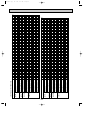
PKA-RP1.6GAL PKA-RP2GAL
INDOOR UNIT
MF
DC14V
ZNR
POWER
1 3 5
CN03
(RED)
1 3 5
FC
TB4
YLW
S1
ORN
S2
BRN
S3
1
2
3
CONT.BOARD
CN02(WHT)
BLK
WHT
YLW
ORN
BRN
RED
WHT
BLK
C
FAN
(WHT)
F1
3
2
1
3 2 1
I.B
P.B
CN2S(WHT)
2
1
]
OUTDOOR
CN01(BLU)
VANE
CN6V
(WHT)
1 2
POWER
CN2D(WHT)
X4
CN41
CN2L
X4
CN25
CN32
TO OUTDOOR UNIT
6
MV
WIRELESS
CN90
(WHT)
9
9
W.B
LED3 LED2 LED1
SW1
J15
J14
J13
J12
J11
J24
J23
J22
J21
SWE SW2
ON
OFF
D.SENSOR
CN31
(WHT)
1 2 3
REMOCON
CN22
(BLU)
HEATER INTAKE LIQUID PIPE
CN20
CN21
CN29
CN24
(RED) (WHT) (BLK)
(YLW)
1 2
1 2
1 2
1 2
RU
RECEIVER LED1 LED2 SW2 SW1
1 2
2
1
TRANSMISSION WIRES DC12V
R.B
TB5
TH1
TH2
CNB
BZ
TH5
CN2
1 2
TB6
Please set the voltage using the
remote controller.
For the setting method,please refer to
the indoor unit Installation Manual.
SW2
SW1
Manufacture
Service board
MODELS
Manufacture
Service board MODELS
ON
OFF
J11 J12 J13 J14 J15
SYMBOL
P.B
F1
ZNR
I.B
CN2L
CN32
CN41
SW1
SW2
SWE
X4
FC
LED1
LED2
LED3
Manufacture
Service board
1234
12345
NAME
1.6GAL
J21 J22 J23 J24
SYMBOL
INDOOR POWER BOARD
FUSE(4A)
VARISTOR
INDOOR CONTROLLER BOARD
CONNECTOR(LOSSNAY)
CONNECTOR(REMOTE SWITCH)
CONNECTOR(HA TERMINAL-A)
JUMPER WIRE(MODEL SELECTION)
JUMPER WIRE(CAPACITY CORD)
SWITCH(EMERGENCY OPERATION)
RELAY(FAN MOTOR)
FAN PHASE CONTROL
POWER SUPPLY(I.B)
POWER SUPPLY(R.B)
TRANSMISSION(INDOOR-OUTDOOR)
C
MF
MV
TB4
TB5
TH1
TH2
TH5
NAME
1234
ON
OFF
2GAL
J21 J22 J23 J24
SYMBOL
W.B
CAPACITOR(FAN MOTOR)
RU
FAN MOTOR
BZ
VANE MOTOR
TERMINAL BLOCK(INDOOR/OUTDOOR
LED1
LED2
CONNECTING LINE)
SW1
TERMINAL BLOCK(REMOTE CONTROLLER
SW2
TRANSMISSION LINE)(OPTION)
R.B
ROOM TEMP.THERMISTOR
CN2
(0°C/15k",25°C/5.4k" DETECT)
TB6
PIPE TEMP.THERMISTOR/LIQUID
(0°C/15k",25°C/5.4k" DETECT)
COND./EVA.TEMP.THERMISTOR
(0°C/15k",25°C/5.4k" DETECT)
NAME
WIRELESS REMOTE CONTROLLER BOARD
RECEIVING UNIT
BUZZER
LED(RUN INDICATOR)
LED(HOT ADJUST)
SWITCH(HEATING ON/OFF)
SWITCH(COOLING ON/OFF)
REMOTE CONTROLLER BOARD(OPTION)
CONNECTOR(PROGRAM TIMER)
TERMINAL BLOCK(REMOTE CONTROLLER
TRANSMISSION LINE)
NOTES:
1.Since the outdoor side electric wiring may change be sure to check the outdoor unit electric wiring for servicing.
2.Indoor and outdoor connecting wires are made with polarities,make wiring matching terminal numbers(S1,S2,S3).
3.Make sure that the main power supply of the booster heater is independent.
4.Symbols used in wiring diagram above are,
:Connector, :Terminal (block).
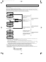
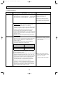
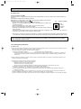
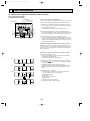
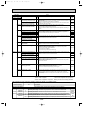
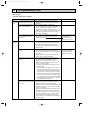
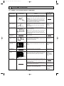
[Self-diagnosis]
An explanation of the wireless remote controller self checking operations,check codes,buzzer sounds and LED signals are given
below. For check codes and symptom see the table below please.
1.Press the CHECK button twice continuously.
3.While pointing the remote controller toward the unit's
· CHECK begins to light and refrigerant address display
receiver, press the h button.
"00" begins to blink.
· The check code will be indicated by the number of times
· Start this operation from the status of remote controller
that the buzzer sounds from the receiver section and the
display turned off.
number of blinks of the operation lamp.
2.Press the TEMP ▼ , ▲ buttons.
4.While pointing the remote controller toward the unit's
receiver, press the ON/OFF
button.
· Set the refrigerant address of the indoor unit that is to
· Self-check mode is canceled.
be self-diagnosed.
· Set the refrigerant address of outdoor unit by outdoor unit
dip switch "SW1".
(Refer to installation manual of outdoor unit for the detail.)
Check code
P1
P2
P6
P8
P9
U0~UL
F1~F9
E6~EF
---FFFF
Operation lamp
1SEC.FLASHo1
1SEC.FLASHo2
1SEC.FLASHo6
1SEC.FLASHo8
1SEC.FLASHo2
(0.4+0.4)SEC.FLASHo1
Buzzer sound
Single beepo1
Single beepo2
Single beepo6
Single beepo8
Single beepo2
Double beepo1
DIFFERENT FROM ABOVE Sounds other than
above
OFF
No sound
Triple beep
OFF
Symptom
Abnormality of room temperature thermistor(TH1).
Abnormality of pipe temperature thermistor/Liquid(TH2).
Freezing /overheating protection is working.
Abnormality of pipe temperature.
Abnormality of pipe temperature thermistor/ Cond./Eva.(TH5).
Abnormality in outdoor unit. Refer to outdoor unit wiring diagram.
Abnormality of signal transmission between indoor unit and outdoor unit
("EE" indicates abnormality of combination).
No trouble generated in the past.
No corresponding unit.
7
ON
OFF
OCT04A-1.qxp
04.9.29 9:14 AM
Page 8
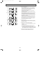
PKA-RP2.5FAL PKA-RP3FAL PKA-RP4FAL
SYMBOL
NAME
INDOOR POWER BOARD
P.B
F1
FUSE(4A)
ZNR VARISTOR
I.B
INDOOR CONTROLLER BOARD
CN2L CONNECTOR(LOSSNAY)
CN32 CONNECTOR(REMOTE SWITCH)
CN41 CONNECTOR(HA TERMINAL-A)
SW1 JUMPER WIRE(MODEL SELECTION)
SW2 JUMPER WIRE(CAPACITY CODE)
SWE SWITCH(EMERGENCY OPERATION)
X4
RELAY(FAN MOTOR)
FC
FAN PHASE CONTROL
LED1 POWER SUPPLY(I.B)
LED2 POWER SUPPLY(R.B)
LED3 TRANSMISSION(INDOOR-OUTDOOR)
SYMBOL
C
MF
MV
TB4
NAME
SYMBOL
NAME
CAPACITOR(FAN MOTOR)
W.B
WIRELESS REMOTE CONTROLLER BOARD
FAN MOTOR
RU RECEIVING UNIT
VANE MOTOR
BZ
BUZZER
LED1 LED(RUN INDICATOR)
TERMINAL BLOCK(INDOOR/OUTDOOR
LED2 LED(HOT ADJUST)
CONNECTING LINE)
SW1 SWITCH(HEATING ON/OFF)
TERMINAL BLOCK(REMOTE CONTROLLER
SW2 SWITCH(COOLING ON/OFF)
TRANSMISSION LINE)(OPTION)
ROOM TEMPERATURE THERMISTOR R.B
REMOTE CONTROLLER BOARD(OPTION)
(0°C/15kΩ, 25°C/5.4kΩ DETECT)
CN2 CONNECTOR(SCHEDULE TIMER)
PIPE TEMPERATURE THERMISTOR/LIQUID
TB6 TERMINAL BLOCK(REMOTE CONTROLLER
(0°C/15kΩ, 25°C/5.4kΩ DETECT)
TRANSMISSION LINE)
CONDENSER / EVAPORATOR TEMPERATURE
THERMISTOR (0°C/15kΩ, 25°C/5.4kΩ DETECT)
TB5
TH1
TH2
TH5
INDOOR UNIT
2
1
MF
3
2
1
1 2 3
YLW
ORN
BRN
1 3 5
FAN
(WHT)
POWER
CN03 1 3 5
(RED)
BLK
WHT
RED
WHT
BLK
C
I.B
DC14V
CONT.BOARD
CN02 (WHT)
Manufacture
HEATER
CN24
(YLW)
1 2
J11
J12
J13
J14
J15
J21
J22
J23
J24
SW1
MODELS
1234
3FAL
J21J22J23J24
ON
OFF
1234
4FAL
J21J22J23J24
MV
9
CN25
RECEI
-VER
PIPE
CN29
(BLK)
1 2
Manufacture Service board
J21J22J23J24
ON
OFF
TH1
TO OUTDOOR UNIT
WIRELESS
CN32 CN90
(WHT)
LIQUID
CN21
(WHT)
1 2
INTAKE
CN20
(RED)
1 2
TB4
S1
S2
S3
6
REMOCON
CN22
(BLU)
1 2
2
2.5FAL
12345
YLW
ORN
BRN
CN2L
SW2
1234
J11J12J13J14J15
Service board
OUTDOOR
CN01 (BLU)
1
2
3
CN41
LED3 LED2 LED1
SW1
ZNR
VANE
CN6V
(WHT)
X4
SWE SW2
ON
OFF
F1
1 2
POWER
CN2D (WHT)
X4
FC
P.B
CN2S(WHT)
TH2
TH5
1
TB5
W.B
BZ
CNB
R.B
TB6
2 1
RU LED1 LED2 SW2 SW1
TRANSMISSION WIRES DC12V
Please set the voltage
using the remote controller.
For the setting method,
please refer to the indoor
unit Installation Manual.
ON
OFF
ON
OFF
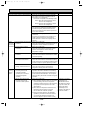
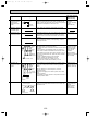
NOTES:
1.Since the outdoor side electric wiring may change be sure to check the outdoor unit electric wiring for servicing.
2.Indoor and outdoor connecting wires are made with polarities, make wiring matching terminal numbers(S1, S2, S3).
3.Symbols used in wiring diagram above are,
:Connector, :Terminal (block).
[Self-diagnosis]
An explanation of the wireless remote controller self checking operations, check codes, buzzer sounds and LED signals are given
below. For check codes and symptom see the table below please.
3.While pointing the remote controller toward the unit's
1.Press the CHECK button twice continuously.
receiver, press the h button.
• CHECK begins to light and refrigerant address display
• The check code will be indicated by the number of times
"00" begins to blink.
that the buzzer sounds from the receiver section and the
• Start this operation from the status of remote controller
number of blinks of the operation lamp.
display turned off.
4.While pointing the remote controller toward the unit's
2.Press the TEMP ▼ , ▲ buttons.
receiver, press the ON/OFF
button.
• Set the refrigerant address of the indoor unit that is to
• Self-check mode is canceled.
be self-diagnosed.
• Set the refrigerant address of outdoor unit by outdoor unit
dip switch "SW1".
(Refer to installation manual of outdoor unit for the detail.)
Check code
P1
P2
P4
P5
P6
P8
P9
U0~UL
F1~F9
E6~EF
---FFFF
Operation lamp
1SEC.FLASH ✕ 1
1SEC.FLASH ✕ 2
1SEC.FLASH ✕ 4
1SEC.FLASH ✕ 5
1SEC.FLASH ✕ 6
1SEC.FLASH ✕ 8
1SEC.FLASH ✕ 2
(0.4+0.4)SEC.FLASH ✕ 1
Buzzer sound
Single beep ✕ 1
Single beep ✕ 2
Single beep ✕ 4
Single beep ✕ 5
Single beep ✕ 6
Single beep ✕ 8
Single beep ✕ 2
Double beep ✕ 1
DIFFERENT FROM ABOVE Sounds other than
above
No sound
OFF
Triple beep
OFF
Symptom
Abnormality of room temperature thermistor(TH1).
Abnormality of pipe temperature thermistor/Liquid(TH2).
Abnormality of drain sensor(DS).
Malfunction of drain-up machine.
Freezing /overheating protection is working.
Abnormality of pipe temperature.
Abnormality of pipe temperature thermistor/ Condenser/Evaporator(TH5).
Abnormality in outdoor unit. Refer to outdoor unit wiring diagram.
Abnormality of signal transmission between indoor unit and outdoor unit
("EE" indicates abnormality of combination).
No trouble generated in the past.
No corresponding unit.
8
CN2
OCT04A-1.qxp
04.9.29 9:14 AM
Page 9
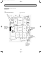
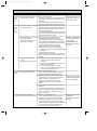
PCA-RP2GA PCA-RP2.5GA PCA-RP3GA
PCA-RP4GA PCA-RP5GA
PCA-RP6GA
SYMBOL
P.B
F1
ZNR
I.B
CN2L
CN32
CN41
SW1
SW2
SWE
X1
X4
FC
LED1
LED2
LED3
C
MF
NAME
INDOOR POWER BOARD
FUSE(4A)
VARISTOR
INDOOR CONTROLLER BOARD
CONNECTOR(LOSSNAY)
CONNECTOR(REMOTE SWITCH)
CONNECTOR(HA TERMINAL-A)
JUMPER WIRE(MODEL SELECTION)
JUMPER WIRE(CAPACITY CORD)
SWITCH(EMERGENCY OPERATION)
RELAY(DRAIN PUMP)
RELAY(FAN MOTOR)
FAN PHASE CONTROL
POWER SUPPLY(I.B)
POWER SUPPLY(R.B)
TRANSMISSION(INDOOR-OUTDOOR)
CAPACITOR(FAN MOTOR)
FAN MOTOR
SYMBOL
MV
DP
DS
TB4
TB5
NAME
VANE MOTOR
DRAIN-UP MACHINE(OPTION)
DRAIN SENSOR(OPTION)
SYMBOL
W.B
RU
BZ
LED1
LED2
SW1
SW2
TERMINAL BLOCK(INDOOR/OUTDOOR CONNECTING LINE)
TERMINAL BLOCK(REMOTE CONTROLLER
TRANSMISSION LINE)
ROOM TEMP.THERMISTOR
(0:/15k",25:/5.4k" DETECT)
TH2
PIPE TEMP.THERMISTOR/LIQUID
(0:/15k",25:/5.4k" DETECT)
TH5
COND./EVA.TEMP.THERMISTOR
(0:/15k",25:/5.4k" DETECT)
R.B
REMOTE CONTROLLER BOARD
CN2 CONNECTOR(SCHEDULE TIMER)
TB6 TERMINAL BLOCK(REMOTE CONTROLLER
TRANSMISSION LINE)
TB2
TERMINAL BLOCK(HEATER)
TH1
INDOOR UNIT
DC14V
MF
DP
D.U.M
CNP 1 3
(BLU)
SW1
J15
J14
J13
J12
J11
J24
J23
J22
J21
SWE SW2
ON
OFF
D.SENSOR
CN31
(WHT)
1 2 3
INTAKE LIQUID
CN20 CN21
(RED) (WHT)
1 2
1 2
When installing drain-up
machine(Optional part).
CN31 DRAIN SENSOR
(WHT) 1 2 3
DS
MODELS
1 2
1 2
TB4
S1
S2
S3
OUTDOOR
CN01(BLU)
}
TO
OUTDOOR
UNIT
P2,P3 TYPE
6
6
6
MV
MV
P4~P6 TYPE
5
5
MV
9
BZ
2
1
YLW
ORN
BRN
CNB
RU
RECEIVER LED1 LED2 SW2 SW1
W.B
TRANSMISSION WIRES DC12V
R.B
CN2
WWhen installing optional
1 2
drain-up machine,disconnect
TB6
TH1 TH2 TH5
the CN31 jumper connector
[Servicing]
and replace it with the
drain sensor(DS).
Fasten terminal of the terminal board "TB4" equips lock system.
To remove the fastened terminal,pull it while pressing the protruding
portion(locking lever)of the terminal.The fastened terminal protruding
portion should face upward.
TB5
SW1
SW2
Manufacture
2GA
<For manufacture>
J21 J22J23 J24
1234
2.5GA
J11 J12 J13 J14 J15
J21 J22 J23 J24
1234
3GA
J21 J22 J23 J24
1234
4GA
<For service board>
12345
ON
OFF
J21 J22 J23 J24
1234
J21 J22 J23 J24
1234
6GA
J21 J22 J23 J24
Please set the voltage using
the remote controller.
For the setting method,
please refer to the indoor
unit Installation Manual.
[Self-diagnosis]
Service board
1234
5GA
PIPE REMOCON
CN29 CN22
(BLK) (BLU)
1 2
1 2
BLU
BLU
X4
BLK
BLK
X4
POWER
VANE
1 3 5
1 2
CN03
6
CN6V
POWER (WHT)
(RED)
CN2D(WHT)
CN41 CN2L
X1
WIRELESS
CN90
CN25
CN32
(WHT)
X1
LED3 LED2 LED1
BLK
BLK
FAN 1 3 5
(WHT)
ZNR
1
2
3
CONT.BOARD
CN02(WHT)
BLK
WHT
RED
WHT
BLK
YLW
ORN
BRN
C
F1
3
2
1
(OPTION)
1 2 3
FC
P.B
CN2S(WHT)
2
1
I.B
NAME
WIRELESS REMOTE CONTROLLER BOARD(OPTION)
RECEIVING UNIT
BUZZER
LED(RUN INDICATOR)
LED(HOT ADJUST)
SWITCH(HEATING ON/OFF)
SWITCH(COOLING ON/OFF)
ON
OFF
ON
OFF
ON
OFF
ON
OFF
ON
OFF
1.For details on how to operate self-diagnosis with the wireless
remote control,refer to the technical manuals etc.
NOTES:
1.Since the outdoor side electric wiring may change be sure to
check the outdoor unit electric wiring for servicing.
2.Indoor and outdoor connecting wires are made with polarities,make
wiring matching terminal numbers(S1,S2,S3).
3.Make sure that the main power supply of the booster heater is
independent.
4.Symbols used in wiring diagram above are,
:Connector,
: Terminal (block).
[Emergency operation procedure]
1.When the wired remote control or the indoor unit microcomputer has failed,but all other
components work properly, if you set the switch(SWE) on the indoor control panel ON,the indoor
unit will begin Emergency Operation.
When Emergency Operation is activated, the indoor unit operates as follows:
(1)Indoor fan is running at high speed.
(2)Drain-up machine(optional) is working.
ON
OFF
9
OCT04A-1.qxp
04.9.29 9:14 AM
Page 10
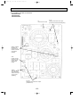
PEA-RP3EA.TH-A PEA-RP5EA.TH-A
PEA-RP4EA.TH-A PEA-RP6EA.TH-A
SYMBOL
I.B
CN2L
CN32
CN41
LED1
LED2
LED3
SW1
SW2
SWE
X4
X5
X6
NAME
INDOOR CONTROLLER BOARD
CONNECTOR(LOSSNAY)
CONNECTOR(REMOTE SWITCH))
CONNECTOR(HA TERMINAL-A)
POWER SUPPLY(I.B)
POWER SUPPLY(R.B)
TRANSMISSOION(INDOOR • OUTDOOR)
JUMPER WIRE(MODEL SELECTION)
JUMPER WIRE(CAPACITY CORD)
SWITCH(EMERGENCY OPERATION)
RELAY(FAN MOTOR)
RELAY(FAN MOTOR)
RELAY(FAN MOTOR)
SYMBOL
P.B
F1
ZNR
R.B
CN2
TB6
NAME
INDOOR POWER BOARD
FUSE(4A)
VARISTOR
REMOTE CONTROLLER BOARD
CONNECTOR(PROGRAM TIMER)
TH1
ROOM TEMPERATURE THERMISTOR
(0˚C/15kΩ, 25˚C/5.4kΩ DETECT)
TH2
PIPE TEMPERATURE THERMISTOR/LIQUID
(0˚C/15kΩ, 25˚C/5.4kΩ DETECT)
TH5
COND./EVA. TEMPERATURE THERMISTOR
(0˚C/15kΩ, 25˚C/5.4kΩ DETECT)
SYMBOL
NAME
C
CAPACITOR(FAN MOTOR)
MF
FAN MOTOR
TB4
TERMINAL BLOCK
(INDOOR/OUTDOOR CONNECTING LINE)
TERMINAL BLOCK(REMOTE
CONTROLLER TRANSMISSON LINE)
INDOOR UNIT
CN2S(WHT)
MF
2
1
WHT
BLK
1 POWER
2 CN2D
(WHT)
POWER 1 3 5
CN03
(RED)
3 CN31
2
WIRELESS
CN90
1
(WHT)
2 LIQUID
CN21
REMOCON
1 (WHT)
LED3 LED2 LED1
CN22
(BLU) 2
2 INTAKE
SWE PIPE
CN20
1
1 (RED)
ON
CN29 2 1
(BLK)
OFF
CN41
CN2L
CN24
CN32
FAN 1 3 5 7
(WHT)
X6 X5 X4
X6 X5 X4
SW2
YLW
ORN
BRN
C
ORN
I.B
BLK
BLU
BRN
WHT
RED
2 3 4 1 5 6
SW1
3
2
1
DC14V
J15
J14
J13
J12
J11
J24
J23
J22
J21
3EA
4EA
5EA
Manufacture Service board
<For manufacture>
1 2 3 4
J21J22J23J24
1 2 3 4
J11J12J13J14 J15 J21J22J23J24
1 2 3 4
<For service board> J21J22J23J24
1 2 3 4 5
6EA
SW2
ON
OFF
1 2 3 4
J21 J22 J23 J24
ON
OFF
ON
OFF
ON
OFF
ON
OFF
YLW
ORN
BRN
S1
S2
S3
TO OUTDOOR UNIT
CONT.BOARD OUTDOOR
CN02(WHT)
CN01(BLU)
P.B
TB5
BLU
BLU
2
1 TRANSMISSION WIRE
DC12V
R.B
1 2
TB6
TH5 TH2 TH1
SW1
1
2
3
ZNR
CN2
MODELS
TB4
F1
[NOTES]
1.Since the outdoor side electric wiring may change be sure to check the
outdoor unit electric wiring for servicing.
2.Indoor and outdoor connecting wires are made with polarities,make wiring
matching terminal numbers(S1,S2,S3).
3.Symbols used in wiring diagram above are,
:Connector, :Terminal (block).
[Self diagnosis]
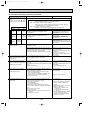
1.When pressing the CHECK switch twice on the remote controller,the unit
changes to the self-diagnosis mode and will display the check code by
LED(light Emitting Diode)
Refer to the right table for the check codes and abnormarities.
10
OCT04A-1.qxp
04.9.29 9:14 AM
Page 11
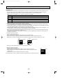
PEAD-RP1.6EA.UK PEAD-RP2EA.UK
PEAD-RP3EA.UK
PEAD-RP4EA.UK
PEAD-RP3EA1.UK PEAD-RP4EA1.UK
PEAD-RP2.5EA.UK
PEAD-RP5EA.UK
PEAD-RP6EA.UK
PEAD-RP5EA1.UK PEAD-RP6EA1.UK
11
OCT04A-1.qxp
04.9.29 9:14 AM
Page 12
PEAD-RP2.5GA
PEAD-RP3GA
PEAD-RP4GA
12
OCT04A-1.qxp
04.9.29 9:14 AM
Page 13
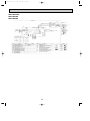
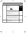
PUHZ-RP1.6VHA
PUHZ-RP2VHA
PUHZ-RP2.5VHA
PUHZ-RP3VHA
PUHZ-RP3VHA-A
W1
W2
W1 MODEL SELECT
MODELS
SW6
ON
MODELS
SW6
ON
1.6V OFF
2.5V OFF
1 2 3 4 5 6
2V
ON
OFF
1 2 3 4 5 6
3V
1 2 3 4 5 6
ON
OFF
1 2 3 4 5 6
W2 Only PUHZ-RP2.5, 3VHA.
13
OCT04A-1.qxp
04.9.29 9:14 AM
Page 14
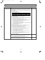
PUHZ-RP4VHA
PUHZ-RP5VHA
PUHZ-RP6VHA
PUHZ-RP4VHA1
PUHZ-RP5VHA1
PUHZ-RP6VHA1
PUHZ-RP4VHA-A
PUHZ-RP5VHA-A
PUHZ-RP6VHA-A
PUHZ-RP4VHA1-A
PUHZ-RP5VHA1-A
PUHZ-RP6VHA1-A
W1
Only PUHZ-RP4VHA1
PUHZ-RP5VHA1
PUHZ-RP6VHA1
W1 MODEL SELECT
MODELS
SW6
4V
ON
OFF
1 2 3 4 5 6
5V
ON
OFF
1 2 3 4 5 6
6V
ON
OFF
1 2 3 4 5 6
14
OCT04A-1.qxp
04.9.29 9:14 AM
4
Page 15
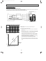
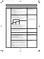
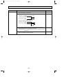
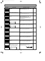
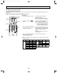
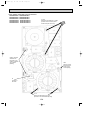
REFRIGERANT SYSTEM DIAGRAM
4-1. Checking operation statuses PUHZ-RP • HA
4-1-1. Measurement points and items
•The table and diagrams below show the measurement item for each measurement point, and the pressure and temperature
near the ISO T1 standard operating conditions.
•Measure the temperature and pressure of each part by following the descriptions in the table.
•Measurement time: Be sure to wait until the refrigerant circuit has stabilized (30 minutes to 1 hour) before taking
measurements.
Pressure/temperature near JIS
standard operating conditions
Measurement item
Measurement method, remarks
A
High pressure (MPa)
B
Low pressure (MPa)
0.55 ~ 1.0
Connect the pressure gauge to the low-pressure check valve.
C
Discharge pipe temperature (:)
50 ~ 100
Measured with piping surface thermometer.
D
Suction pipe temperature (:)
-2 ~ +18
Measured with piping surface thermometer.
E
Indoor intake temperature (:)
F
Indoor outlet temperature (:)
COOL: 2.3 ~ 3.0
Connect the pressure gauge to the high-pressure check valve.
HEAT: 2.0 ~ 3.2
COOL: 27:
Can be displayed on remote controller.
HEAT: 20:
COOL: 8 ~ 20
HEAT: 30 ~ 50
G
Outdoor intake temperature (:)
COOL: 35
H
Outdoor outlet temperature (:)
COOL: 40 ~ 50
HEAT: 7
Measured with piping surface thermometer.
HEAT: 0 ~ 5
Measured with piping surface thermometer.
Notes : The operation statuses vary depending on the compressor's operating frequency because units are inverter-type.
Outdoor
heat exchanger
Ball valve
4-way valve
A
B
D
C
Indoor heat
exchanger
Linear
expansion
valve B
Stop valve
(with service port)
Power
receiver
Compressor
Linear
expansion
valve A
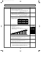
4-1-2. Operation pressure ranges
Permissible operation range
Normal operation range
4.5
Discharge pressure (MPa)
4
Overload operation
3.5
3
Standard operation
2.5
2
1.5
1
0.5
0
0
0.2
0.4
0.6
0.8
Suction pressure (MPa)
15
1
1.2
OCT04A-1.qxp
04.9.29 9:14 AM
Page 16
4-2. Refrigerant System Diagram
PLA-RP1.6AA
PLA-RP1.6AA.UK
PLA-RP3AA
PLA-RP3AA.UK
PLA-RP3AA1
PLA-RP3AA1.UK
PKA-RP1.6GAL
PKA-RP2.5FAL
PCA-RP2GA
PCA-RP3GA
PEA-RP3EA.TH-A
PEAD-RP1.6EA.UK
PEAD-RP3EA.UK
PEAD-RP3EA1.UK
PEAD-RP2.5GA.UK
PLA-RP2AA
PLA-RP2AA.UK
PLA-RP4AA
PLA-RP4AA.UK
PLA-RP4AA1
PLA-RP4AA1.UK
PKA-RP2GAL
PKA-RP3FAL
PCA-RP2.5GA
PCA-RP4GA
PEA-RP4EA.TH-A
PEAD-RP2EA.UK
PEAD-RP4EA.UK
PEAD-RP4EA1.UK
PEAD-RP3GA.UK
PLA-RP2.5AA
PLA-RP2.5AA.UK
PLA-RP5AA
PLA-RP5AA.UK
PLA-RP5AA1
PLA-RP5AA1.UK
PLA-RP6AA
PLA-RP6AA.UK
PLA-RP6AA1
PLA-RP6AA1.UK
PKA-RP4FAL
PCA-RP5GA
PEA-RP5EA.TH-A
PEAD-RP2.5EA.UK
PEAD-RP5EA.UK
PEAD-RP5EA1.UK
PEAD-RP4GA.UK
PCA-RP6GA
PEA-RP6EA.TH-A
PEAD-RP6EA.UK
PEAD-RP6EA1.UK
Strainer
#50
Heat exchanger
Refrigerant GAS pipe connection
(Flare)
Condenser/evaporator
temperature thermistor
(TH5)
Refrigerant flow in cooling
Refrigerant flow in heating
Refrigerant LIQUID pipe connection
(Flare)
Pipe temperature
thermistor/liquid
(TH2)
Room temperature
thermistor (TH1)
Distributor
with strainer
#50
Strainer
#50
16
OCT04A-1.qxp
04.9.29 9:14 AM
Page 17
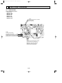
PUHZ-RP1.6VHA
PUHZ-RP2VHA
Heat exchanger
Stop valve
(with service port)
Refrigerant GAS pipe
connection(1/2F)
Thermistor TH6
(Outdoor 2-phase pipe)
Service port
Solenoid valve
(Four-way valve)
Thermistor TH7
(Outdoor)
Strainer
#50
Thermistor TH3
(Outdoor pipe)
Muffler
Distributor
High pressure
switch 63H
Thermistor TH4
(Discharge)
Muffler
Linear
expansion valve B
Compressor
Power
receiver
Linear expansion valve A
Stop valve
Refrigerant LIQUID pipe
connection(1/4F)
Strainer
#100
Strainer
#100
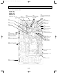
PUHZ-RP2.5VHA
PUHZ-RP3VHA
PUHZ-RP3VHA-A
Ball valve
Refrigerant GAS pipe
connection(5/8F)
Heat exchanger
Strainer
#50
Thermistor TH6
(Outdoor 2-phase pipe)
4-way valve
Oil separator
Bypass valve
Service port
(Low pressure)
Service port
(High pressure)
Capillary tube
O.D.4.0OI.D.2.4OL500
Strainer
#100
Thermistor TH4
(Discharge)
Strainer
#100
Stop valve
(with service port)
Strainer
#100
Power
receiver
Linear
expansion
valve B
Thermistor TH3
(Outdoor pipe)
Distributor
High pressure
switch 63H
Capillary tube
O.D.2.5OI.D.0.6OL1000
Refrigerant LIQUID pipe
connection(3/8F)
Thermistor TH7
(Outdoor)
Muffler Compressor
Linear expansion valve A
Strainer
#100
17
OCT04A-1.qxp
04.9.29 9:14 AM
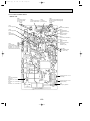
PUHZ-RP4VHA
PUHZ-RP5VHA
PUHZ-RP6VHA
Refrigerant GAS pipe
connection(5/8F)
Page 18
PUHZ-RP4VHA-A
PUHZ-RP5VHA-A
PUHZ-RP6VHA-A
Ball valve Strainer
#50
Heat exchanger
Thermistor TH6
(Outdoor 2-phase pipe)
Solenoid valve
(Four-way valve)
Thermistor TH3
(Outdoor pipe)
Service port
(High pressure)
Muffler
Service port
(Low pressure)
Distributor
Low pressure
switch 63L
Strainer
#100
High pressure
switch 63H
Stop valve
(with service port)
Refrigerant LIQUID pipe
connection(3/8F)
Strainer
#100
Power
receiver
Compressor
Linear expansion valve A
Restrictor
valve
Strainer
#100
Strainer
#100
Strainer
#100
Solenoid valve
(Bypass valve)
Replace filter
PUHZ-RP4VHA1
PUHZ-RP5VHA1
PUHZ-RP6VHA1
Refrigerant GAS pipe
connection(5/8F)
Capillary tube
(O.D.4.0OI.D.3.0OL200)O2pcs
Thermistor TH4
(Discharge)
Strainer
#100
Linear
expansion valve B
PUHZ-RP4VHA1-A
PUHZ-RP5VHA1-A
PUHZ-RP6VHA1-A
Ball valve Strainer
#50
Heat exchanger
Low pressure
switch 63L
Strainer
#100
Distributor
High pressure
switch 63H
Thermistor TH4
(Discharge)
Strainer
#100
Stop valve
(with service port)
Strainer
#100
Thermistor TH3
(Outdoor pipe)
Muffler
Service port
(Low pressure)
Linear
expansion valve B
Thermistor TH7
(Outdoor)
Thermistor TH6
(Outdoor 2-phase pipe)
Solenoid valve
(Four-way valve)
Service port
(High pressure)
Refrigerant LIQUID pipe
connection(3/8F)
Thermistor TH7
(Outdoor)
Power
receiver
Strainer
#100
Compressor
Linear expansion valve A
Restrictor
valve
Strainer
#100
Strainer
#100
Replace filter
Solenoid valve
(Bypass valve)
18
OCT04A-1.qxp
04.9.29 9:14 AM
Page 19
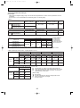
4-3. Applicable extension pipe for each model
4-3-1. 1:1 system
(a) Pipe length
<Table 1> Pipe length for 1:1 system
Liquid OD
[6.35
pipe
t0.8
(mm) Thickness
Gas OD
[12.7
[9.52
pipe
t0.8
t0.8
(mm) Thickness
30m
10m
RP1.6
RP2
RP2.5
RP3
RP4
RP5
RP6
[9.52
[12.7
t0.8
[15.88
[12.7
t1.0
t0.8
50m
50m
10m
10m
30m
30m
10m
10m
30m
30m
30m
30m
t0.8
[15.88
[19.05
[15.88
[19.05
t1.0
t1.0
t1.0
t1.0
30m (*1)
30m (*1)
50m
50m
75m (*2)
75m (*2)
75m (*2)
50m (*1)
50m (*1)
50m (*1)
30m
30m
50m
50m
50m
50m (*1)
50m (*1)
50m (*1)
*1: Set DIP SW8-1 on outdoor unit controller board to ON.
*2: The maximum length is 50 m in case of using existing pipes.
*3: The height difference between indoor and outdoor unit should be kept within 30 m for all models.
[Marks in the table above]
: Normal piping
: It can be used, however, additional refrigerant charge is required when the pipe length exceeds 20m.
: It cannot be used.
: It can be used.
: It can be used, however, the capacity is lowered.
Refer to (c) Capacity correction.
Refer to <table 4>.
(b) Adjusting the amount of refrigerant
• Additional refrigerant charge is not necessary for the pipe length up to 30 m. When the pipe length exceeds 30 m or service
(refrigerant replacement) is performed, charge proper amount of refrigerant for each pipe length referring to table below.
Use refrigerant R410A. Use charge hose exclusive for R410A.
• When charging additional refrigerant, charge the refrigerant from low-pressure side of the port valve using a safety charger.
• Make sure that air purge for this unit at refrigerant replacement is performed from both high-pressure check valve and service port. (If air purge is performed only from one of them, air in not purged enough.)
• When replacing refrigerant, charge the refrigerant from service port. When charged refrigerant is less than specified amount,
charge the refrigerant again from low pressure side of the port valve using a safety charger.
• Tighten the service port cap (nut) of stop valve firmly. The tightening torque is 12 to 16 N·m. (For the prevention of slow-leak)
• Check additional refrigerant charging amount referring to table 4 when liquid pipe is one size larger than standard diameter,
and table 2 when the pipe is standard diameter.
<Table 2> Additional refrigerant charging amount for pipe of standard diameter
Additional refrigerant charging amount for pipe
Permitted
Height
Number of
length exceeding 30 m (kg)
Outdoor unit
pipe length
difference
bends
—
—
—
—
75m
50m 51
60m 61
31
40m 41
PUHZ-RP1.6, 2V
50m or less
0.2kg
0.4kg
—
—
PUHZ-RP2.5, 3V
PUHZ-RP4-6V, RP4-6V1
50m or less
0.6Kg
1.2Kg
—
—
75m or less
0.6kg
1.2kg
1.8kg
2.4kg
15
30m or
above
<Table 3>
Outdoor unit
PUHZ-RP1.6, 2V
PUHZ-RP2.5, 3V
PUHZ-RP4-6V
PUHZ-RP4-6V1
Permitted Additional refrigerant charging amount for recharging (above) and pipe length exceeding 30m (below) (kg)
pipe length 10m or below 11 — 20m 21 — 30m 31 — 40m 41 — 50m 51 — 60m 61 — 75m
50m or less
50m or less
75m or less
75m or less
2.1
3.1
5.1
4.6
2.3
3.3
5.3
4.8
2.5
3.5
5.5
5.0
2.7
2.9
—
—
0.2
0.4
—
—
4.1
4.7
—
—
0.6
1.2
—
—
6.1
6.7
7.3
7.9
0.6
1.2
1.8
2.4
5.6
6.2
6.8
7.4
0.6
1.2
1.8
2.4
<Table 4> Additional refrigerant charging amount for liquid pipe which is one size larger than standard diameter
Liquid pipe dia Chargeless Max. pipe length Additional refrigerant charging amount
RP1.6, 2
[9.52
20m
30m
60 g addition per 1 m when pipe length exceeds 20 m
RP2.5, 3
[12.7
20m
30m
100 g addition per 1 m when pipe length exceeds 20 m
RP4-6
[12.7
20m
50m
100 g addition per 1 m when pipe length exceeds 20 m
19
OCT04A-1.qxp
04.9.29 9:14 AM
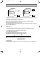
Page 20
(c) Capacity correction
Cooling and heating capacity is lowered according to pipe length. Capacity can be obtained by referring to the capacity
curves below. When the diameter of gas pipe is one size smaller than standard diameter, cooling capacity is lowered comparing to the standard diameter. The lowered capacity can be obtained by referring to capacity curves for gas pipe which is
one size smaller than standard size.
Corrected pipe length (m) = actual pipe length (m) + number of bends x 0.3 (m)
1 Capacity curves for PUHZ-RP • HA model <Standard size>
100
Heating
Heating RP1.6, 2, 2.5,
3, 4, 5 and 6 models
Cooling RP1.6, 2.5 models (Up to 55m for RP1.6,
2, 2.5, 3 model)
Cooling RP3 model
95
Capacity ratio [%]
Cooling
90
85
Cooling RP2, 4 models
(Up to 55m for RP2
model)
Cooling RP5 model
80
75
Cooling RP6 model
Note: The permitted pipe length is up to 55m for RP1.6, 2, 2.5, 3 model.
70
5
10 15 20 25 30 35 40 45 50 55 60 65 70 75 80
Corrected pipe length
2 Capacity curve for PUHZ-RP1.6, 2 models
<When gas pipe is one size smaller than standard size>
100
Heating RP1.6, RP2
Capacity ratio [%]
95
90
Cooling RP2
85
Cooling RP1.6
80
5
10
15
20
25
30
35
Corrected pipe length
20
40
45
50
55
OCT04A-1.qxp
04.9.29 9:14 AM
Page 21
3 Capacity curve for PUHZ-RP2.5, 3 models
<When gas pipe is one size smaller than standard size>
100
Heating RP2.5, RP3
Capacity ratio [%]
95
90
Cooling RP2.5
85
80
Cooling RP3
5
10
15
20
25
30
35
Corrected pipe length
40
45
50
4 When gas pipe is one size larger than standard size for PUHZ-RP4, 5 and 6.
1 Capacity can be obtained by referring to capacity curves of standard size.
21
55
OCT04A-1.qxp
04.9.29 9:14 AM
Page 22
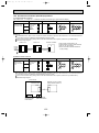
4-3-2. Synchronized twin and triple
(a) Pipe length
Please note that refrigerant piping length, bend number and height difference of indoor units are specified for each unit
combination.
Note: Be sure to use our Multi-distributor for distributing pipe to use existing piping.
<Table 5>
Permitted total piping
length A + B + C
Synchronized twin
Outdoor
unit
PUHZ-RP3VHA
PUHZ-RP3VHA-A
PUHZ-RP4-6VHA
PUHZ-RP4-6VHA-A
Chargeless piping
length A + B + C
Indoor unit’s height
difference [B and C]
Bend number
w2
8 m or less
15 at most
50 m or less
30 m or less
75 m or less
<Table 6>
Permitted total piping
length A + B + C + D
Synchronized twin
Charge-less piping
Indoor unit’s height difference Bend number
length A + B + C + D [B and C] [C and D] [B and D]
w2
Outdoor
unit
PUHZ-RP6VHA
70 m or less
30 m or less
8 m or less
15 at most
PUHZ-RP6VHA-A
Note 1: If total piping length exceeds charge-less piping length of 30 m, charge additional refrigerant according to the table 7.
<Table 7>
A + B + C (+D)
Additional refrigerant to be charged (kg)
30 m or less 31 - 40 m 41 - 50 m 51 - 60 m 61 - 75 m
Outdoor unit
PUHZ-RP3VHA
PUHZ-RP3VHA-A
PUHZ-RP4-6VHA
PUHZ-RP4-6VHA-A
Not required
0.6
w Charge additional
refrigerant from
the check valve
connected to the
pipe of low-pressure
side in indoor unit.
1.2
1.8
2.4
Note 2: Bends number (w 2) should be within 8 for each combination, A + B, A +C and A + D, and 15 in all.
Note 3: Height difference between indoor and outdoor unit is referred to no matter which unit is located higher or lower.
<Table 8> Pipe length for twin of RP 3 - 6 (Piping length: A + B + C)
RP3 Twin (RP1.6✕2)
RP4 Twin (RP2✕2)
RP5 Twin (RP2.5✕2)
RP6 Twin (RP3✕2)
Main pipe diameter [A]
Liquid [6.35 Liquid [9.52 Liquid [9.52 Liquid [12.7 Liquid [9.52 Liquid [12.7 Liquid [9.52 Liquid [12.7
Gas [12.7 Gas [15.88 Gas [15.88 Gas [19.05 Gas [15.88 Gas [19.05 Gas [15.88 Gas [19.05
Branch pipe Liquid [6.35
Gas [12.7
diameter
Liquid [9.52
[B and C]
Gas [15.88
Liquid [12.7
Gas [19.05
✕
50 m
✕
50 m
50 m
✕
✕
✕
75 m(✽2)
50 m(✽1)
50 m(✽1)
✕
✕
75 m(✽2)
✕
✕
50 m(✽1)
✕
✕
75 m(✽2)
✕
✕
50 m(✽1)
✕
<Table 9> Pipe length for triple of RP6 (Piping length: A + B + C + D)
Main pipe diameter [A]
✽1 ··· Set DIP SW8-1 on outdoor unit control circuit board to ON.
Liquid [9.52 Liquid [12.7
✽2 ··· When using existing piping, pipe length should be 50 m at most.
Gas [15.88 Gas [19.05
✽3 ··· Height difference between indoor and outdoor unit should be
kept within 30 m in every case.
Branch pipe Liquid [6.35
75 m(✽2)
50 m(✽1)
Gas [12.7
diameter
[Marks in table]
Liquid [9.52
··· Normal piping
50 m
50 m(✽1)
[B,C and D] Gas [15.88
··· It can be used with some changes of piping length and the
Liquid [12.7
Gas [19.05
✕
✕
amount of refrigerant to be charged.
✕ ··· It cannot be used.
22
OCT04A-1.qxp
04.9.29 9:14 AM
Page 23
Synchronized twin
Branch
pipe B
Indoor
unit
Branch
pipe C
Indoor
unit
30 m or less
1 m or less
30 m or less
1 m or less
Indoor
unit
Synchronized triple
Optional
distributing pipe
Multi-distributor
Main
pipe A
Branch
pipe B
Branch
pipe C
Branch
pipe D
Indoor
unit
Indoor
unit
Optional
distributing pipe
Multi-distributor
Outdoor
unit
Main
pipe A
Outdoor
unit
1. Keep Stop valve in outdoor unit fully closed (as it is shipped), and after completing refrigerant piping connection, conduct air
purge from service port of stop valve at outdoor unit.
2. After air purging, make the valve rod of stop valve at outdoor unit fully open.
Now refrigerating cycle is complete between indoor and outdoor unit.
Handle stop valve following the indication on outdoor unit.
Caution:
• Be sure to apply refrigerating oil to flare sheet face. Never apply it to screws. (As it causes flare nut loosening.)
• Use double spanner for piping connection.
• Be sure to check gas leak by using leak detector or soapy water.
• Use attached parts for refrigerant piping to provide correct insulation to the connection of indoor unit side in accordance with
attached explanation sheet.
• Be sure to provide anoxidized brazing.
(b) Adjusting the amount of refrigerant
(i) In case of RP 3 twin
Check the additional refrigerant to be charged referring to table 2 when using pipe of size referred in table 8.
(ii) In case of RP4 - 6 twin or RP6 triple
When using liquid pipe one size larger than standard diameter for main pipe A, calculate the amount of additional
refrigerant referring to 2 below.
1 When using piping of standard diameter or gas pipe one size larger than standard diameter for main pipe A.
Check the additional refrigerant to be charged referring to table 2 like 1:1 system.
2 When using liquid pipe one size larger than standard diameter for main pipe A.
[In case of RP4-6 using liquid pipe of [12.7]
• When total length of extension pipe (main pipe and branch pipe) is less than 20 m.
No adjustment is required for refrigerant. (Chargeless)
• When total length of extension pipe (main pipe and branch pipe) is more than 20 m.
Calculate the amount of additional refrigerant, referred to as W (g) in the following, using the equation below and add
proper amount of refrigerant. If W is less than or equal to 0, no additional charge is required. (Chargeless)
[Additional refrigerant]
W (g) = {100(g) ✕ L1} + {60(g) ✕ L2} + {30(g) ✕ L3} - 2000(g)
Note: Put “0” in L1-3 if it is not used.
L1: Liquid pipe length of [12.7 (m)
L2: Liquid pipe length of [9.52 (m)
L3: Liquid pipe length of [6.35 (m)
(c) Capacity correction
Apply pipe length between indoor and outdoor unit which is the longest of all for the calculation of capacity lowering according
to each pipe length.
23
OCT04A-1.qxp
5
04.9.29 9:14 AM
Page 24
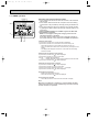
HOW TO CHECK THE PARTS
5-1. INDOOR UNIT
• Common parts
Parts name
Check points
Room temperature
thermistor
(TH1)
Disconnect the connector then measure the resistance using a tester.
(Surrounding temperature 10:~30:)
Pipe temperature
thermistor/ liguid (TH2)
Condenser/evaporator
temperature thermistor
(TH5)
Drain sensor
Normal
Abnormal
4.3k"~9.6k"
Open or short
(Refer to below for a detail.)
Measure the resistance between the terminals using a tester.
Measure the resistance after 3 minutes have passed since the power supply was intercepted.
(Surrounding temperature 0:~60:)
1
2
3
Normal
Abnormal
0.6k"~6.0k"
Open or short
(Refer to below for a detail.)
<Thermistor Characteristic graph>
< Thermistor for lower temperature >
Thermistor R0=15kΩ ± 3%
Fixed number of B=3480K ± 2%
Rt=15exp { 3480(
0:
10:
20:
25:
30:
40:
50
Room temperature thermistor(TH1)
Pipe temperature thermistor(TH2)
Condenser/evaporator temperature
thermistor(TH5)
1
273+t
40
Resistance (k")
Thermistor for
lower temperature
1 )}
273
15kΩ
9.6kΩ
6.3kΩ
5.2kΩ
4.3kΩ
3.0kΩ
30
20
10
0
10
Drain sensor
-20 -10 0 10 20 30 40 50
Temperature (:)
< Thermistor for drain sensor >
9
8
Thermistor R0=6.0kΩ ±5%
Fixed number of B=3390K ±2%
0:
10:
20:
25:
30:
40:
60:
Resistance (k")
Rt=6exp { 3390( 1
273+t
7
1 )}
273
6.0kΩ
3.9kΩ
2.6kΩ
2.2kΩ
1.8kΩ
1.3kΩ
0.6kΩ
6
5
4
3
2
1
0
-20
24
0
20 40 60
Temperature (:)
80
OCT04A-1.qxp
04.9.29 9:14 AM
Page 25
PLA-RP1.6AA
PLA-RP1.6AA.UK
PLA-RP3AA
PLA-RP3AA1
PLA-RP3AA.UK
PLA-RP3AA1.UK
PLA-RP2AA
PLA-RP2AA.UK
PLA-RP4AA
PLA-RP4AA1
PLA-RP4AA.UK
PLA-RP4AA1.UK
PLA-RP2.5AA
PLA-RP2.5AA.UK
PLA-RP5AA
PLA-RP5AA1
PLA-RP5AA.UK
PLA-RP5AA1.UK
Parts name
Check points
Vane motor
Measure the resistance between the terminals using a tester.
(Surrounding temperature20:)
Fan motor
Relay connector
1
Red
2 White
Abnormal
15k"
Open or short
Normal
Motor terminal PLA-RP1.6, 2, 2.5, 3AA
PLA-RP4, 5, 6AA
or
PLA-RP1.6, 2, 2.5, 3AA.UK PLA-RP4, 5, 6AA.UK
PLA-RP4, 5, 6AA1
Relay connector PLA-RP3AA1
2
PLA-RP3AA1.UK
3
Protector
OPEN :130:
CLOSE:80i20:
Drain pump
Normal
Measure the resistance between the terminals using a tester.
(Winding temperature 20:)
1
3 Black
Red-Black
87.2"
28.7"
White-Black
104.1"
41.6"
1
Normal
Abnormal
2
290"
Open or short
Red
PKA-RP1.6GAL
Parts name
Fan motor (MF)
Relay connector
Red
2
White
3
Black
1
2
3
Vane motor (MV)
Red
2
Pink
Red – Black
120.5"
White – Black
111.3"
Red – Orange
3 6 1
Parts name
Fan motor (MF)
Relay connector
1
2
Red
1
White
3 Black
2
3
Protector
OPEN : 130i 5:
CLOSE : 80i 20:
Vane motor (MV)
Open or short
PKA-RP3FAL
M
PKA-RP4FAL
Check points
Measure the resistance between the terminals using a tester.
(Winding temperature 20:)
Normal
Motor terminal
or
Abnormal
RP2.5
RP4
Relay connector
RP3
Red – Black
99.5"
62.6"
White – Black
103.9"
74.0"
Open or short
Measure the resistance between the terminals using a tester.
(Surrounding temperature 20:~30:)
4 Orange
Pink
186~214"
Red – Pink
PKA-RP2.5FAL
2
Abnormal
Brown – Yellow
Brown – Blue
Red
Normal
Connector
M
Yellow Brown Blue
5
Open or short
Measure the resistance between the terminals using a tester.
(Surrounding temperature 20:~30:)
4 Orange
5
PKA-RP2GAL
Check points
Measure the resistance between the terminals using a tester.
(Winding temperature 20:)
Normal
Motor terminal
or
Abnormal
RP1.6 , RP2
Relay connector
Protector
OPEN : 125i 5:
CLOSE : 79i 15:
Connector
Normal
Abnormal
RP2.5, RP3, RP4
Brown –Y ellow
Yellow Brown Blue
Brown – Blue
3 6 1
Red – Orange
Abnormal
PLA-RP4, 5, 6AA1.UK
Measure the resistance between the terminals using a tester.
(Winding temperature 20:)
Red
1
PLA-RP6AA
PLA-RP6AA1
PLA-RP6AA.UK
PLA-RP6AA1.UK
Open or short
186~214"
Red – Pink
25
Open or short
OCT04A-1.qxp
04.9.29 9:14 AM
PCA-RP2GA
PCA-RP4GA
Page 26
PCA-RP2.5GA
PCA-RP5GA
PCA-RP3GA
PCA-RP6GA
Parts name
Check points
Measure the resistance between the terminals using a tester.
(Winding temperature 20:)
Fan motor
Relay connector
1
Red
2 White
3 Black
1
Motor terminal
or
Relay connector
2
Normal
RP2
RP2.5, RP3
RP4
RP5, RP6
Red – Black
70.6"
45.0"
43.7"
20.4"
White – Black
69.6"
44.8"
55.3"
20.7"
3
Protector
OFF : 130i 5:
ON : 80i 20:
Vane motor
Red
2
Pink
M
Brown – Blue
3 6 1
Pink
Red – Orange
186~214"
140~160"
Normal
Connector
M
Abnormal
Open or short
Abnormal
RP4, RP5, RP6
Brown – Yellow
Brown – Blue
Red
Yellow
Blue
3
1
Open or short
140~160"
Red – Orange
Red – Pink
Drain-up
mechanism (Option)
Gray
RP2.5, RP3
Red – Pink
2 Orange
5
RP2
Brown – Yellow
Yellow Brown Blue
4
Normal
Connector
4 Orange
5
Measure the resistance between the terminals using a tester.
(Winding temperature 20:)
1
Normal
Abnormal
2
195"
Open or short
Gray
PEA-RP3EA.TH-A PEA-RP4EA.TH-A PEA-RP5EA.TH-A PEA-RP6EA.TH-A
Parts name
Fan motor (MF)
Protector
(PEA-RP3,4,5EA)
OPEN :135:
CLOSE:86i15:
(PEA-RP6EA)
OPEN :150:
CLOSE:96i15:
White
Orange
Red
Brown
Blue
Black
Abnormal
Check points
Measure the resistance between the terminals using a tester.
(Winding temperature 20:)
Motor terminal
or
Relay connector
Normal
Abnormal
PEARP3EA.TH-A RP4EA.TH-A RP5EA.TH-A RP6EA.TH-A
White – Black
28.6"
20.6"
15.3"
10.2"
Black – Blue
12.5"
8.1"
5.1"
5.2"
Blue – Brown
4.3"
3.2"
2.7"
3.1"
Brown – Red
23.6"
16.0"
14.5"
12.1"
26
Open or short
Open or short
OCT04A-1.qxp
04.9.29 9:14 AM
Page 27
PEAD-RP1.6EA.UK PEAD-RP2EA.UK
PEAD-RP3EA.UK
PEAD-RP4EA.UK
PEAD-RP3EA1.UK PEAD-RP4EA1.UK
Parts name
Check points
Fan motor (MF)
Measure the resistance between the terminals using a tester.
(Winding temperature 20:)
PEAD-RP3EA(1).UK
Motor terminal
or
Relay connector
Black
Blue
Gray – Black
Gray
Red
PEAD-RP2.5EA.UK
PEAD-RP5EA.UK
PEAD-RP6EA.UK
PEAD-RP5EA1.UK PEAD-RP6EA1.UK
White
Protector
OPEN :150:
CLOSE:96i15:
(White or Red open)
Black – Blue
(White or Red open)
Blue – Red
(White or Red open)
PEAD-RP4,5,6EA(1).UK
Blue
Motor terminal
or
Relay connector
Red
(White or Red open)
Black
Gray-Black
Normal
Abnormal
PEAD-RP1.6, 2, 2.5EA.UK
PEAD-RP3EA(1).UK
43.5"
Open or short
14.74"
57.5"
Normal
Abnormal
PEADRP4EA(1).UK
RP5EA(1).UK RP6EA(1).UK
24.76"
10.27"
4.78"
2.11"
18.99"
20.75"
36.63"
25.44"
White
Blue – Black
Gray
Protector
OPEN :135:
CLOSE:86i15:
Black – Red
(White or Red open)
Gray – Red
(White or Red open)
Open or short
PEAD-RP2.5GA
PEAD-RP3GA
PEAD-RP4GA
27
OCT04A-1.qxp
04.9.29 9:14 AM
Page 28
5-2. OUTDOOR UNIT
PUHZ-RP1.6HA
PUHZ-RP2VHA
PUHZ-RP4VHA
PUHZ-RP5VHA
PUHZ-RP4VHA1
PUHZ-RP5VHA1
PUHZ-RP4VHA-A PUHZ-RP5VHA-A
PUHZ-RP4VHA1-A PUHZ-RP5VHA1-A
PUHZ-RP2.5VHA PUHZ-RP3VHA
PUHZ-RP6VHA
PUHZ-RP6VHA1
PUHZ-RP6VHA-A
PUHZ-RP6VHA1-A
Check points
Parts name
Disconnect the connector then measure the resistance using a tester.
(Surrounding temperature 10:~30:)
Thermistor (TH3)
<Outdoor pipe>
Abnormal
Normal
Thermistor (TH4)
<Discharge>
TH4
Thermistor (TH6)
<Outdoor 2-phase pipe>
TH3
Thermistor (TH7)
<Outdoor>
TH7
160k"~410k"
TH6
Open or short
4.3k"~9.6k"
TH8
39k"~105k"
Thermistor (TH8)
<Heat sink>
Fan motor(MF1,MF2) Measure the resistance between the terminals using a tester.
(Winding temperature 20:)
Red
W
White
Black
V
U
Pin number of relay
connector is different
from that motor
connector
Solenoid valve coil
<Four-way valve>
(21S4)
Relay connector
Normal
RP1.6V, 2V
RP2.5-6V
Abnormal
Red — Black
Black — White
66.5±3.3"
Open or short
15.1±0.5"
White — Red
Measure the resistance between the terminals using a tester.
(Surrounding temperature 20:)
Normal
Abnormal
RP1.6-3V
RP4-6V
2350±170"
1370±100"
Open or short
Motor for compressor Measure the resistance between the terminals using a tester.
(Winding temperature 20:)
(MC)
U
Normal
V
Abnormal
RP1.6V, 2V
RP2.5V, 3V
RP4-6V
0.300"~0.340"
0.865"~0.895"
0.266"
W
Linear expansion valve Disconnect the connector then measure the resistance using a tester.
(Winding temperature 20:)
( LEV(A),LEV(B) )
Normal
Abnormal
(1) - (6)
(1) - (4)
(2) - (5)
(2) - (3)
Red - White Red - Orange Brown - Yellow Brown - Blue
Open or short
3
Red
M 2
6
1
5
4
1
Brown 2
Blue 3
Orange 4
Yellow 5
White 6
Solenoid valve coil
<Bypass valve>
(SV)
RP2.5-6VHA only
46±4"
Measure the resistance between the terminals using a tester.
(Surrounding temperature 20:)
Normal
1197±10"
Abnormal
Open or short
28
Open or short
OCT04A-1.qxp
04.9.29 9:14 AM
Page 29
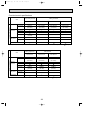
5-3. COMPRESSOR TECHNICAL DATA
(at 20°C)
Unit
PUHZ-RP1.6,2VHA PUHZ-RP2.5,3VHA PUHZ-RP4,5,6VHA
Compressor model
SNB130FLBH
TNB220FMBH
ANV33FDAMT
U-V
Winding
Resistance U-W
(")
W-V
0.300 ~ 0.340
0.865 ~ 0.895
0.266
0.300 ~ 0.340
0.865 ~ 0.895
0.266
0.300 ~ 0.340
0.865 ~ 0.895
0.266
29
OCT04A-1.qxp
04.9.29 9:14 AM
Page 30
HOW TO CHECK THE COMPONENTS
<Thermistor feature chart>
50
Low temperature thermistors
• Thermistor <Outdoor pipe> (TH3)
• Thermistor <Outdoor 2-phase pipe> (TH6)
• Thermistor <Outdoor> (TH7)
Resistance (k")
40
Thermistor R0 = 15k' ± 3%
B constant = 3480K ± 2%
1
1
Rt =15exp{3480( 273+t – 273 )}
0:
15k'
30:
4.3k'
10: 9.6k'
40:
3.0k'
20: 6.3k'
25: 5.2k'
30
20
10
0
-20 -10 0 10 20 30 40 50
Temperature (:)
200
Medium temperature thermistor
• Thermistor <Heat sink> (TH8)
Thermistor R50 = 17k' ± 2%
B constant = 4150K ± 3%
Resistance (k")
150
1
1
Rt =17exp{4150( 273+t – 323)}
0:
25:
50:
70:
90:
180k'
50k'
17k'
8k'
4k'
100
50
0
High temperature thermistor
25
50
75
100
Temperature (:)
125
500
• Thermistor <Discharge> (TH4)
Thermistor R120 = 7.465k' ± 2%
B constant = 4057K ± 2%
400
20: 250k'
30: 160k'
40: 104k'
50: 70k'
60: 48k'
Resistance (k")
1
1
Rt =7.465exp{4057( 273+t – 393)}
70:
34k'
80:
24k'
90: 17.5k'
100: 13.0k'
110: 9.8k'
300
200
100
0
30
25
50
75
Temperature (:)
100
120
OCT04A-2.qxp
04.9.29 9:15 AM
Page 31
Linear expansion valve
(1) Operation summary of the linear expansion valve.
• Linear expansion valve open/close through stepping motor after receiving the pulse signal from the outdoor controller board.
• Valve position can be changed in proportion to the number of pulse signal.
<Connection between the outdoor controller board and the linear expansion valve>
Outdoor controller board
DC12V
Red
1
Brown
2
[4
Blue
3
[3
Orange
4
[2
Yellow
5
[2
[1
White
6
[1
LEV
Drive circuit
3
M
2
1
5
4
6
[4
[3
Connector LEV-A
LEV-B
<Output pulse signal and the valve operation>
Output
(Phase)
Output
2
1
3
4
5
6
7
Opening a valve : 8 → 7 → 6 → 5 → 4 → 3 → 2 → 1 → 8
Closing a valve : 1 → 2 → 3 → 4 → 5 → 6 → 7 → 8 → 1
8
[1
ON ON OFF OFF OFF OFF OFF ON
[2
OFF ON
[3
OFF OFF OFF ON
[4
OFF OFF OFF OFF OFF ON ON ON
ON ON OFF OFF OFF OFF
ON ON OFF OFF
The output pulse shifts in above order.
❈ 1. When linear expansion valve operation stops, all output phase
become OFF.
❈ When the switch is turned on, 700 pulse closing valve signal will
be sent till it goes to point A in order to define the valve position.
(The pulse signal is being sent for about 20 seconds.)
(2) Linear expansion valve operation
Open
Valve position (capacity)
C
Close
When the valve moves smoothly, there is no noise or vibration
occurring from the linear expansion valve : however, when the
pulse number moves from B to A or when the valve is locked,
more noise can be heard than normal situation.
No noise is heard when the pulse number moves from B to A in
case coil is burn out or motor is locked by open-phase.
❈ Noise can be detected by placing the ear against the screw driver handle while putting the screw driver to the linear expansion
valve.
Open
500 pulse
Opening a valv
all the way
A
Close
B
Pulse number
Extra tightning (about 200 pulse)
31
OCT04A-2.qxp
04.9.29 9:15 AM
Page 32
(3) How to attach and detach the coil of linear expansion valve
<Composition>
Linear expansion valve is separable into the main body and the coil as shown in the diagram below.
Main body
Coil
Lead wire
Stopper
<How to detach the coil>
Hold the lower part of the main body (shown as A) firmly so that
the main body does not move and detach the coil by pulling it
upward.
Be sure to detach the coil holding main body firmly. Otherwise
pipes can bend due to pressure.
A
<How to attach the coil>
Hold the lower part of the main body (shown as A) firmly so that
the main body does not move and attach the coil by inserting it
downward into the main body. Then securely attach the coil stopper to pipe B. (At this time, be careful that stress is not added to
lead wire and main body is not wound by lead wire.) If the stopper is not firmly attached to pipe B, coil may be detached from
the main body and that can cause defective operation of linear
expansion valve.
To prevent piping stress, be sure to attach the coil holding the
main body of linear expansion valve firmly. Otherwise pipe may
break.
B
A
Be sure to attach the
stopper to pipe B.
32
OCT04A-2.qxp
04.9.29 9:15 AM
6
Page 33
MICROPROCESSOR CONTROL
6-1. System construction
(1) System construction
A-control model which just wires the connecting line between the indoor and outdoor unit and supply the power is applicable to
any models of standard (1:1), twin and triple. (Refer to 2 Start-up system.)
Standard 1:1
Synchronized twin. Triple
Outdoor unit; (00)...Refrigerant address
(SW1; 3~6)
Indoor unit; (00)–w
Indoor unit number
(00)
(auto setting)
Refrigerant address
(receiving from the
outdoor unit)
2
2
2
1
1
2
4
4
System construction
(00)-2 4
(00)-3
3
3
Main Sub
Main Sub
Various setting
(00)-1 4
1Unit (indoor/outdoor) power supply L/N
2Connecting line between the indoor and
outdoor; S1/S2/S3, Polarized 3-wire
3Remote controller transmission line; Non
polarized 2-wire
4Auxiliary heater exclusive power supply; L/N
1Unit (indoor/outdoor) power supply L/N
2Connecting line between the indoor and
outdoor; S1/S2/S3, Polarized 3-wire
3Remote controller transmission line; Non
polarized 2-wire
4Auxiliary heater exclusive power supply; L/N
Remote control main/sub setting necessity
(In case of 2 remote controllers)
Remote control main/sub setting necessity
(In case of 2 remote controllers)
Indoor unit
No setting
No setting (initial setting)
Outdoor unit
No setting
No setting (initial setting)
Remote controller
Remarks
(1) Indoor unit number is set automatically
Group control
(00)
1
2
System construction
4
(01)
1
2
(00)-1 4
3
(00)-2 4
(02)
1
2
2
(01)-1 4
(02)-1 4
3
3
Outdoor unit; (00)...Refrigerant address
(SW1; 3~6)
Indoor unit; (00)–w
Indoor unit number
(auto setting)
Refrigerant address
(receiving from the
2
outdoor unit)
(02)-2
3
Main
Various setting
1Unit (indoor/outdoor) power supply L/N
2Connecting line between the indoor and outdoor; S1/S2/S3, Polarized 3-wire
3Remote controller transmission line; Non polarized 2-wire
4Auxiliary heater exclusive power supply; L/N
Remote controller
Indoor unit
Remote control main/sub setting necessity
(In case of 2 remote controllers)
No setting (initial setting)
Outdoor unit
Refrigerant address setting; SW1; 3~6
Remarks
(1) Indoor unit number is set automatically
(2) When the refrigerant address of the unit is "00", Remote controller is supplied.
33
OCT04A-2.qxp
04.9.29 9:15 AM
Page 34
(2) The transmitting specification for “A” control
1Wiring regulations
Section
The maximum length of
total wiring
Communications from remote controllers
500m
Communications between indoor and outdoor units
80m (Including the wiring among indoor units
in addition to the wiring between indoor and
outdoor units)
The maximum numbers
for connection
One outdoor unit can connect up to three
One remote controller can connect and operate
indoor units.
up to 16 indoor units by grouping them.❋1
One group can connect up to two remote controllers.
❋1 Remote controller considers multiplex units as
a single group.
The cables applicable
0.3mm2 to 1.25mm2
Others
The wirings as follows are not allowed:
• The wiring that the indoor units of the same
refrigerant system are connected through TB5.
• The wiring which directly connects the terminals
for remote controllers.
Use either flat-type cable (3 cores: {1.6mm or
more) or wires in the table below.
❋2 The diameter of the cables depends on
each unit.
The core wire connected to terminal S2 shall be
placed at the center of flat-type cable.
2Transmitting specification
Section
Transmitting speed
Communications from remote controllers
83.3 bit/sec. (1 bit = 12ms)
Communications between indoor and outdoor units
83.3 bit/sec. (1 bit = 12ms)
Normal transmission
The terminal for remote controller transmits signals every 7.5 seconds; the indoor unit whose
refrigerant address is “0” responds them.
Outdoor unit transmits signals every 3 seconds;
all the connected indoor units respond them.
Modulation
The waveform modulates at 50kHz.
There is no modulation.
Detection of abnormal
communication
When transmitting error is detected for three consecutive minutes.
When transmitting error is detected for three
consecutive minute.
For 220-240V 50Hz
The cable shall not be lighter than design 245 IEC or 227 IEC.
The cable length may vary depending on the condition of installation, humidity or materials, etc.
Cross section
of cable
Wire size
(mm2)
Number
of wires
2.5
3
Clockwise : S1-S2-S3
2.5
3
Not applicable
(Because center wire has no cover finish)
1.5
4
From left to right : S1-Open-S2-S3
(45)
✽3
2.5
4
Clockwise : S1-S2-S3-Open
Connect S1 and S3 to the opposite angle
60
✽4
Polarity
Round
Flat
Flat
Round
✽1 : In case that cable with stripe of yellow and green is available.
✽2 : In the flat cables are connected as this picture, they can be used up to 80m.
(3C Flat cable ✕ 2)
S1
S2 S3
2
✽3 : In case of regular polarity connection (S1-S2-S3), wire size is 1.5mm .
✽4 : In case of regular polarity connection (S1-S2-S3).
34
L(m)
(50)
✽1
Not
applicable
✽2
OCT04A-2.qxp
04.9.29 9:15 AM
Page 35
(3) The waveforms of from remote controller communications
The following graphs are the examples for measuring waveforms on the wirings of remote controlled transmission at the
terminal block for remote controller.
a) A measuring example in the sequence of startup
b) A measuring example during normal stop
7.5
seconds
Transmission
from
remote
controller
7.5
seconds
Transmission
from
remote
controller
Transmission
from
indoor unit
5V/div, 1sec/div:
Transmission
from
indoor unit
5V/div, 1sec/div:
c) Expanded waveform 1 (signal 111000....)
d) Expanded waveform 2 (50Hz carrier)
5V/div, 10msec/div:
5V/div, 2µsec/div:
• During normal operation, the remote controller interactively exchanges signals with the indoor unit of refrigerant address “0”.
When the remote controller cannot receive signals from the indoor unit of refrigerant address “0” for 3 minutes, it is considered
as abnormal. E0 is displayed on the remote controller as an error.
35
OCT04A-2.qxp
04.9.29 9:15 AM
Page 36
(4) The waveforms of communications between indoor and outdoor units
The following graphs are the examples for measuring waveforms on the wirings of connecting indoor and outdoor units at
between S2 and S3 of the outdoor terminal block TB1.
a) A measuring example the sequence of startup: 1
Transmission
from
indoor unit
b) A measuring example in the sequence of startup: 2
Transmission
from
outdoor unit
Transmission
from
indoor unit
10V/div, 500msec/div:
c) A measuring example during normal stop
(When one outdoor unit connects one indoor unit)
Transmission
from
indoor unit
Transmission
from
outdoor unit
10V/div, 500msec/div:
d) A measuring example during normal stop
(When one outdoor unit connects two indoor units)
Transmission
from
outdoor unit
Transmission
from
indoor unit
10V/div, 500msec/div:
Transmission
from
one indoor unit
Transmission
from
another
indoor unit
10V/div, 500msec/div:
c) Expanded waveform
10V/div, 50msec/div:
• During normal operation, outdoor unit interactively exchanges signals with all the connected indoor units.
• When outdoor unit cannot receive signals for three minutes from an indoor unit due to any trouble like cable disconnection, it
is considered as abnormal and the outdoor unit stops. E8 is displayed on the remote controller. This is to avoid independent
operation of indoor units.
36
OCT04A-2.qxp
04.9.29 9:15 AM
Page 37
(5) Start-up system
A control unit is applicable to any models of standard (1:1), twin and triple without switch setting according to carrying out the
below process automatically when the power is supplied.
When the power is supplied, following processes of 1 Refrigerant address transmitting, 2 Power supply control to remote
controller, 3 Set number of the connected unit, 4 Set number of the indoor unit, 5 Duplication detection, 6 Collecting the unit
information and 7 Collecting the operation data are carried out as shown on the figure.
Also when detecting the duplicated setting in the step 5, back to the first step and reset it.
Power ON
1 Refrigerant address
transmitting
2 Refrigerant
address "0"?
; Transmitting the switch setting
contents on the outdoor unit
remote controller
(SW1-3~6)
YES
; Feeding control to remote
controller
Feeding the indoor unit of the
refrigerant address “0”
Power supply control
to remote controller
NO
EA error if 4 minutes have
passed since the power is
supplied.
3 Set number of the
connected unit
4 Set number of the
indoor unit
5 Duplication
detection
; If there are 2 or more specified indoor unit, back to the
first step.
YES
EB error if 4 minutes have
passed since the power is
supplied.
NO
; Collecting the vane, louver
information and transmittance
to the remote controller.
6 Collecting the unit
information
; Collecting the preceding operation setting information and
transmittance to the remote
controller.
7 Collecting the
operation data
EC error if 4 minutes have
passed since the power is
supplied.
Set up finish
<<Feature>>
A. Start-up time from the second time will be shorter since setting of the number of connected units is memorized once set.
Start-up time can be estimated as following;
•When installing ... 1~2 minutes (Depending the number of connecting units)
•Since the second time .... 20 seconds ~ 1 minute (Depending the number of connecting units)
w When the above processing does not finish, even if 4 minutes have passed, consider the processing an error and
Ea, Eb or Ec will be displayed.
However if power is not supplied to the indoor unit due to miss-wiring or looseness of the connecting lines
between the indoor and outdoor unit, there will be no display on the remote controller. Also when the data can not
be received from the outdoor unit, E6 is displayed on the remote controller after 6 minutes.
B. When replacing the p.c.board, only the unit number which has had it`s p.c.board replaced is reset.
Even if the power supply is reset, the unit number which has not had it`s replaced does not change.
C. Automatic set unit is possible to confirm by blinking the frequency of LED3 in the indoor controller board.
At intervals of approx. 3 seconds, the number of the unit-number blinks.(Example:The unit(unit number:2) blinks twice at
3-second intervals.
Example
2 blinking Not lighted
3 seconds
2 blinking
37
OCT04A-2.qxp
04.9.29 9:15 AM
Page 38
Function/control specifications
4-way ceiling cassette
Ceiling concealed
Item
PLA-RP•AA
Function / specification
Fan
PEA-RP•EA
PEAD-RP•EA
PEAD-RP•GA
Number of fan speed
4
2
2
2
Drive method
Pulsation
Tap-changing
Tap-changing
Tap-changing
(AC motor)
(AC motor)
(AC motor)
(AC motor)
Up/down
Provided
—
—
—
auto vane
Swing function
—
—
—
Shutter mechanism
—
—
—
—
—
—
—
—
—
—
—
—
—
—
Motor type
Stepping
(12V DC)
Left/right
Provided
swing louver
Motor type
Drain pump
—
Note: The parts marked
Ceiling suspended
Wall mounted
Item
Function / specification
Fan
PCA-RP•GA
PKA-RP•GAL
PKA-RP•FAL
Number of fan speed
4
4
2
Drive method
Phase control
Phase control
Phase control
(AC motor)
(AC motor)
(AC motor)
Up/down
Provided
auto vane
Swing function
Shutter mechanism
Motor type
Left/right
Provided
swing louver
Motor type
Drain pump
Stepping
Stepping
Stepping
(12V DC)
(12V DC)
(12V DC)
—
—
—
—
—
—
—
Note: The parts marked
38
are optional.
are optional.
OCT04A-2.qxp
04.9.29 9:15 AM
7
Page 39
INDOOR UNIT CONTROL
7-1. COOL operation
Control modes
1. Compressor
Control details
1-1. Thermoregulating function (Function to prevent restarting for 3 minutes)
• Room temperature ] desired temperature +1:···Compressor ON
Remarks
w1 The thermoregulating
function is provided in the
outdoor unit.
• Room temperature [ desired temperature ···Compressor OFF
The indoor unit transmits
the indoor room
temperature and set
ON when compressor stopped (including when thermostat is OFF) temperature data to
outdoor unit, then the
Crankcase heater switches ON when 220-240V AC current is applied between
outdoor unit controls
thermoregulation.
connectors CH 1 and 2 on the outdoor control board.
Crankcase heater: OFF when compressor operates
1-2. Anti-freezing control
Detected condition : When the liquid pipe temperature (TH2 ) or Condenser/
Refer to w2.
Refer to w3.
Evaporator temperature (TH5 ) (w3) is 2: or less (w4) in 16
minutes from compressors start up, anti-freezing control
starts and the compressor will be suspended.
Released condition : The timer which prevents reactivating is set for 3 minutes,
and anti- freezing control is cancelled when any one of the
following conditions is satisfied.
1 Liquid pipe temperature (TH2) and Condenser / Evaporator
temperature (TH5) turn 10: or above.
2 The condition of the compressor stop has become
complete by thermoregulating, etc.
3 The operation modes became mode other than COOL.
4 The operation stopped.
1-3. Frozen protection
Detected condition : 1 When the indoor pipe temperature (TH2 ) or Condenser/
Evaporator temperature (TH5 ) continues -15: for 3 minutes
since 3 minutes has passed after the compressor start, the
compressor stops and then the mode changes to prevent
restarting for 6 minutes. After restarting of 6 minutes, when
the indoor pipe temp. (TH2) or Condenser / Evaporator
temperature (TH5) continues -15 or less for three minutes again
by the time 16 minutes have passed, the frozen protection
operates. (P6)
Detected condition : 2 In case the indoor unit continues to be under the anti-freezing
control for 9 minutes or more, the unit will be in a state of the
suspensive abnormality. Restart the compressor after releasing
the anti-freezing control. The suspensive abnormality will be
cancelled if the compressor keeps operating for 20 minutes.
However, the suspensive abnormality will turn into the
abnormality if the anti-freezing control works again for 9
minutes during that period. On the other hand, the suspensive
abnormality will be cancelled if the anti-freezing control
works for less than 9 minutes
Released condition : When the operation stops by the remote controller operation.
2. Fan
By the remote controller setting (switch of 4 speeds or 2 speeds)
When determining the abnormality of the pipe temp. low speed fan is fixed.
Type
Fan speed notch
4 speeds type
[Low] [Medium2] [Medium1] [High]
2 speeds type
[Low]
[High]
w2 Compare liquid pipe temperature to Condenser/ Evaporator temperature, and the lower one is applied to anti-freezing control.
• Liquid pipe temperature [ Condenser/ Evaporator temperature····· Liquid pipe
• Liquid pipe temperature > Condenser/ Evaporator temperature····· Condenser/ Evaporator pipe
w3 The function of remote controller can change the temperature to start anti-freezing control.
39
OCT04A-2.qxp
04.9.29 9:15 AM
Page 40
Control modes
3. Drain pump
Remarks
Control details
3-1. Drain pump control
•Always drain pump ON during the COOL and DRY mode operation.
(Regardless of the compressor ON/ OFF)
•When the operation mode has changed from the COOL or DRY to the others
(including Stop), OFF the control after the drain pump ON for 3 minutes.
Drain sensor function
• Energize drain sensor at a fixed voltage for a fixed duration. After energizing,
compare the drain sensor’s temperature to the one before energizing, and judge
→
whether the sensor is in the air or in the water.
Basic control system
• While drain pump is turned on, repeat the following control system and judge
whether the sensor is in the air or in the water.
ON
·······Repeat
OFF
Stand by for
a minute
30 sec.
Stand by for
a minute
30 sec.
Detect the
temperature
before
energizing
(T0)
Detect the
temperature
after
energizing
(T1)
Judge whether
the sensor is in
the air or in the
water.
2
3
✻2 If the unit is
without the
drain sensor,
install the
jumper
connector.
Indoor controller
board
1
CN31
→
Timing of
energizing
drain sensor
✻1 Drain sensor
Indoor controller
board
CN31 1
2
3
When installing
the jumper
connector,
determine to
detect
compulsorily in
the air.
•Drain sensor temperature rise (∆t)
•Temperature of drain sensor before current is applied (T0)
•Temperature of drain sensor after current is applied (T1)
[ ∆t = T1 – T0 ]
(1) Initial setting : Start at COOL mode and horizontal vane.
(up/ down vane change) (2) Vane position : Horizontal →Downward A →Downward B →Downward C→Swing
→
4. Vane
(3) Restriction of the downward vane setting
When setting the downward vane A, B and C in [Medium2] or [Low] of the fan
speed notch, the vane changes to horizontal position after 1 hour have passed.
40
✻1 Whether the
unit has a swing
function is listed
in the function/
control specifications.
✻2 See the
function/control
specifications
for the vane
motor type.
✻3 "1Hr"
appears on the
wired remote
controller.
OCT04A-2.qxp
04.9.29 9:15 AM
Page 41
7-2. DRY operation
Control modes
1. Compressor
Remarks
Control details
1-1. Thermoregulating function (Function to prevent restarting for 3 minutes)
Setting the compressor operation time by the thermoregulating signal
and the room temperature (TH1).
Thermoregulating signal ON Room temperature ] desired temperature +1:
Thermoregulating signal OFF Room temperature [ desired temperature
Room temp.
Thermoregulating
signal
Operating
time (min)
OFF time
(min)
ON
9
3
OFF
3
10
Over 18:
Less than 18:
✻1
The thermoregulating
function is provided in
the outdoor unit.
The indoor unit
transmits the indoor
room temperature and
set temperature data to
outdoor unit, then the
outdoor unit controls
thermoregulation.
Compressor operation stop
1-2. Frozen prevention control
No control function
1-3. Frozen protection
Same control as COOL operation
2. Fan
Indoor fan operation controlled depends on the compressor conditions.
Compressor
Fan speed
ON
[Low]
OFF
Stop (✻1)
Note: Remote controller setting is not acceptable.
3. Drain pump
✻1 Note that even when
the compressor is OFF, the
unit starts operating in
[LOW] if the start condition
below is met.
Start condition: The piping
temperature (fluid piping or
2-phase piping) has fallen
to 1: or less.
Release condition: The
piping temperature (fluid
piping or 2-phase piping)
has returned to at least
10:.
Same control as COOL operation
4. Vane
Same control as COOL operation
(up/ down vane change)
5. Louver
(Left/ right change)
✻1 Model which is
installed louver
function.
Remote controller setting
7-3. FAN operation
Control modes
None (always stopped)
2. Fan
Set by remote controller.
3. Drain pump
Remarks
Control details
1. Compressor
Number of fan speeds
Fan speed notches
4
[Low], [Medium2], [Medium1], [High]
2
[Low]
[High]
3.1 Drain pump control
The drain pump turns ON for the specified amount of time when any of the following
conditions is met:
1 ON for 3 minutes after the operation mode is switched from COOL or DRY to
another operation mode (FAN).
2 ON for 6 minutes after the drain sensor is determined to be submerged using the
liquid level detection method given below.
3 ON for 6 minutes after indoor piping (liquid piping) temperature - indoor intake
temperature [ -10:, AND the drain sensor input is at the short or open level.
(If condition 2 or 3 is still being met after the drain pump has been turned ON for 6
minutes, the drain pump is kept ON for a further 6 minutes.)
3.2 Liquid level detection method
The liquid level is detected by determining whether or not the drain sensor is
submerged, based on the amount the temperature rises after self-heating the
sensor. This process is performed if any of the following conditions is met:
1 Drain pump is ON.
2 Indoor piping (liquid piping) temperature - indoor intake temperature [ -10:
3 Indoor piping (liquid piping) temperature or indoor intake temperature is at the
short or open level temperature.
4 Every hour after the drain pump has been switched from ON to OFF.
Same as the control performed during the COOL operation, but with no restriction
4. Vane
(up/ down vane change) on the vane's downward blow setting.
41
OCT04A-2.qxp
04.9.29 9:15 AM
Page 42
7-4. HEAT operation
Control modes
1. Compressor
Remarks
Control details
1-1. Thermoregulating function (Function to prevent restarting for
3 minutes)
✻1
The thermoregulating function is
• Room temperature [ desired temperature-1: ···Compressor ON
provided in the outdoor unit.
• Room temperature ] desired temperature ···Compressor OFF
The indoor unit transmits the indoor
room temperature and set temperature
data to outdoor unit, then the outdoor
unit controls thermoregulation.
1-2. Over- rise protection control
Detected control : When Condenser/ Evaporator temp.
turns 74: or more, less than 90: after starting
compressor, stop the compressor, then the mode changes to
restarting compressor, stop the compressor, then the mode
changes to restarting protection mode after 6 minutes.
After restarting after 6 minutes when the Condenser/
Evaporator temperature became 74: or more, less than 90:
by the time 10 minutes pass, the mode changes to over-rise
protection control.
Release control : When the operation stops by the remote
controller.
2. Auxiliary heater 2-1. Thermoregulating function
When the mode is not Hot adjust or Defrosting mode during
HEAT compressor operation, the controller changes to
auxiliary heater ON.
✻1 Models without auxiliary heater also
control the units in the same way as
shown in the left.
Thermoregulating function follows the below table with
according to desired temp. and room temp.
Temperature difference
Auxiliary heater
z<0
OFF
0[ z<3
Keeping condition
3[z
ON
temperature difference Z=Desired temperature - Room temperature
2-2. Over-rise prevention control
During the HEAT compressor operation, when the Condenser/
Evaporator temperature becames 63: or more, over-rise
prevention control operates and the auxiliary heater prohibits
for ON operation. When the indoor Condenser/Evaporator
temperature is being 58: or less for 3minutes during
over-rise prevention, over-rise prevention control will be
released and auxiliary heater ON will be allowed.
(However, in case the Condenser/Evaporator temperature
becomes 66: or more during over-rise prevention, 40: or
less will be the requirement to release over-rise prevention
control and allow auxiliary heater to be ON.)
42
✻2 During the over-rise prevention
control, "Airflow increasing" in the
indoor fan is controlled.
( Only the model of fan 4-speed)
OCT04A-2.qxp
04.9.29 9:15 AM
Page 43
Control details
Control modes
3. Fan
Controlled by the remote controller (4-speed or 2-speed)
Give priority to under-mentioned controlled mode
3-1. Hot adjuster mode
3-2. Preheating exclusion mode
3-3. Thermostat OFF mode (When the compressor off by the
thermoregulating)
3-4. Cool air prevention mode (Defrosting mode)
3-5. Capacity increasing mode
Remarks
✻1
Fan speed change notch
Refer to the model function table
3-1. Hot adjuster mode
The fan controller becomes the stand by (hot adjuster) mode
for the following conditions.
1 When starting the HEAT operation
2 When starting the compressor by the thermoregulating
3 When release the HEAT defrosting operation
Hot adjuster mode ✻1
Set fan speed by the remote controller
✻1 "STAND BY" will be displayed
during the stand by (hot adjuster)
mode.
[Low]
[Extra Low]
A
B
C
A: Stand by (hot adjuster) mode start
B: 5 min have passed since the condition A or the indoor
Condenser/ Evaporator temperature turned 35: or more
C: 2 min have passed since the condition A
(Terminating the stand by (hot adjuster) mode)
3-2. Preheating exclusion mode
When the condition changes the auxiliary heater ON to OFF
(thermoregulating or operation stop, etc), the indoor fan
operates in [Low] mode for 1 minute.
✻1 This control is same for the model
without auxiliary heater.
3-3. Thermostat OFF mode
✻1 Fan's airflow volume, when thermostat
When the compressor stops by the thermoregulating, etc., the
is OFF, can be changed by selecting the
indoor fan operates in [Extra low].
function of remote controller.
3-4. Cool air prevention mode (Heat defrosting mode)
After "not adjustment" mode is finished, the indoor fan will
stop if 1 or 2 mentioned below is detected.
When receiving "DEFROST" from the outdoor unit, the mode
changes to defrosting mode.
Pipe temp. (Condenser/ Evaporator) - Room temp. [ -5deg
··· 1
-5deg < pipe temp. (Condenser/ Evaporator) - Room temp. [ 5deg ··· 2
5deg < pipe temp. (Condenser/ Evaporator) - Room temp.
··· 3
✻1 "DEFROST "will be displayed on the
remote controller during the defrost
operation.
3-5. Fan speed up mode
•When the control changes to over-rise prevention.
The condition of over-rise prevention (Prohibit for auxiliary
heater ON) continues for 10 seconds or more and the set fan
speed is [Low] or [Medium2], the fan speed changes to
[Medium1].
•When the control changes to over-rise prevention during the
heater OFF, the mode changes to capacity increasing mode
immediately.
The capacity increasing mode is canceled by canceling the
over-rise prevention mode.
✻1 This control is applied for only
4-speed model.
43
OCT04A-2.qxp
04.9.29 9:15 AM
Page 44
Control details
Control modes
4. Drain pump
Remarks
4-1. Drain pump control
The drain pump turns ON for the specified amount of time when
any of the following conditions is met (regardless of whether
the compressor is ON or OFF).
Ö1 ON for 3 minutes after the operation mode is switched from
COOL or DRY to another operation mode (HEAT mode).
Ö2 ON for 6 minutes after the drain sensor is determined to be
submerged using the liquid level detection method given
below.
Ö3 ON for 6 minutes after indoor liquid pipe temperature indoor intake temperature becomes -10deg or less AND the
drain sensor input is at the short or open level.
(If condition 2 or 3 is still being met after the drain pump has
been turned ON for 6 minutes, the drain pump is kept ON for
a further 6 minutes.)
w Refer to “7-1. COOL opration” for
liquid level detection method.
4-2. Liquid level detection method
The liquid level is detected by determining whether or not the
drain sensor is submerged, based on the amount of the
temperature rise after the sensor is self-heated. This process
is performed if any of the following conditions is met.
Ö1 Drain pump is ON.
Ö2 Indoor liquid pipe temperature - indoor intake temperature
[ -10deg (except during defrosting)
Ö3 Indoor liquid pipe temperature or indoor intake temperature is
at the short or open level temperature.
Ö4 Every hour after the drain pump has been switched from ON
to OFF.
5. Vane control
(Up/ down vane
change)
✻1 Whether the unit has a swing
(1) Initial setting : OFF → HEAT···[last setting]
function is listed in the
When changing the mode from exception of HEAT
function/control specifications.
to HEAT operation. ···[Downward C]
(2) Air flow direction
[Horizontal]→[Downward A]→Downward B]→Downward C]→[Swing]
(3) Determining position (When the timing motor of AC 200-240V) ✻ See the function/control
Control each air outlet angle considering the starting OFF →
specifications for the vane motor
ON of limit switch to be a standard position (Horizontal or
type.
shutter).
When the standard position can not be determined for 10
minutes, the vane stops at the arbitrary position.
(Vane swing motion for 10 minutes)
(4) Restriction of vane position
The vane is horizontally fixed for the following modes.
(The control by the remote controller is temporally invalidated
and control by the unit.)
•Compressor OFF mode (Thermoregulating, etc.)
•Stand by (hot adjuster) [Extra low] mode
•Cool prevention mode (Determining except for Heat area)
•Heat defrost mode
•Piping (Condenser/ Evaporator) temperature is 37: or less.
44
OCT04A-2.qxp
04.9.29 9:15 AM
Page 45
7-5. AUTO operation
Control modes
Control details
1. Initial value of HEAT mode for room temperature < Desired temperature
operation mode COOL mode for room temperature ] Desired temperature
2. Mode change (1) HEAT mode → COOL mode
Room temperature ] Desired temperature + 2deg. or 15 min. has passed
(2) COOL mode → HEAT mode
Room temperature [ Desired temperature - 2deg. or 15 min. has passed
3. COOL mode
Same control as cool operation
4. HEAT mode
Same control as heat operation
Remarks
✻This mode is provide in the outdoor unit.
The indoor unit follows the instruction
from the outdoor unit.
✻This mode is provide in the outdoor unit.
The indoor unit follows the instruction
from the outdoor unit.
7-6. When unit is stopped Control mode
Control modes
Control details
1. Drain pump
1.1 Drain pump control
The drain pump turns ON for the specified amount of time when
any of the following conditions is met (regardless of whether the
compressor is ON or OFF)
1 ON for 3 minutes after the operation mode is switched from COOL
or DRY to another operation mode (HEAT mode).
2 ON for 6 minutes after the drain sensor is determined to be
submerged using the liquid level detection method given below.
3 ON for 6 minutes after indoor piping (liquid piping) temperature
- indoor intake temperature [ -10deg, AND the drain sensor input is
at the short or open level.
(If condition 2 or 3 is still being met after the drain pump has
been turned ON for 6 minutes, the drain pump is kept ON for a
further 6 minutes.)
1.2 Liquid level detection method
The liquid level is detected by determining whether or not the drain
sensor is submerged, based on the amount the temperature rises
after self-heating the sensor. This process is performed if any of the
following conditions is met:
1 Drain pump is ON.
2 Indoor piping (liquid piping) temperature - indoor intake temperature [ -10deg
(except during defrosting)
3 Indoor piping (liquid piping) temperature or indoor intake temperature
is at the short or open level temperature.
4 Every hour after the drain pump has been switched from ON to OFF.
45
Remarks
OCT04A-2.qxp
04.9.29 9:15 AM
Page 46
7-7. TIMER operation
CABc
D
CENTRALLY CONTROLLED
ON
1Hr.
OFF
˚C
CLOCK
CHECK
˚C
STAND BY
DEFROST
ERROR CODE
TEMP.
NOT AVAILABLE
FILTER
CHECK MODE
TEST RUN
FUNCTION
ON/OFF
FILTER
3
CHECK TEST
PAR-20MAA
TIMER SET
2
1
Available Timer-Interlocked Operation Modes
1. AUTO START/STOP:Allows both start and shutdown to be interlocked
with the timer.
2. AUTO START: Allows automatic start in response to the timer setting
and shutdown to be proceeded by manually pressing the ON/OFF button.
3. AUTO STOP: Allows the start of the operation to be manually invoked
by pressing the ON/OFF button and automatic shutdown based on the
timer setting.
Timer-interlocked operation is available only once for both start
and shutdown in 24 hours.
While D w is displayed, setting and changing of time for timerinterlocked operation is disabled.
In this case, press 3 button once to turn off the D w display on
the remote controller. This is referred to as TIMER OFF operation.
1) Set the current time
1-1) Press the 1 button and “CLOCK” A will be displayed.
1-2) Press the 2 button once to advance the current time by one.
Press the 2 button once to set back the current time by one.
• Press and hold down either button to fast-forward (-reverse) the time
setting.
• The display will disappear from about 10 seconds after the setting
has been entered.
2) Set the time to start the unit as follows
2-1) Press the 1 button and B will be displayed.
2-2) Press the 2 button to set the current time.
2-3) The --:-- field C will be displayed.
The --:-- field C will display a range of time between 23:50 and 00:00.
2-4) Press the 3 button and D will be displayed.
ON
3) Set time to stop the unit as follows
3-1) Press the 1 button and C will be displayed.
3-2) Press the 2 button to set the current time.
3-3) Set the automatic shutdown timer in the --:-- B display.
3-4) Press the 3 button and D will be displayed.
OFF
4) Changing the set times
• Enter a start time/shutdown time.
• Press the 3 button and D will be displayed.
5) Cancelling the set times
• Press the 3 button to clear the remote controller`s display.
Note:
When the air conditioner is operated or is turned off after the timer
setting has finished, the unit will automatically run without interruption the next time it is operated.
46
OCT04A-2.qxp
04.9.29 9:15 AM
8
Page 47
OUTDOOR UNIT CONTROL
8-1. COOL operation
Control modes
1. Compressor
Control details
Remarks
1-1. Thermoregulating function
The outdoor unit receives information of set temperature and intake
temperature from the indoor unit through transmission and judges the
necessity of thermoregulating from their temperature difference.
(Refer to “INDOOR UNIT CONTROL” for detailed detecting method.)
Refer to “8-7.
1-2. Normal control
Compressor operating frequency is controlled according to the difference
Inverter control”
between intake temperature and set temperature in order to let the intake
for “Inverter
temperature be the same as the set temperature
control basic
• Control timing: Once per minute after 3 minutes have passed since the
control
frequency
compressor started.
setting”.
• Frequency changing range: -12Hz to +20Hz
w: However, in the following cases, the frequency changing amount, which is
different from the normal one, will be applied to control the operating frequency.
(1) Frequency is fixed to the minimum just before the compressor is stopped
by the thermoregulating function.
Intake temperature [ Set temperature +0.5: ··· Fixed to the minimum frequency.
Intake temperature [ Set temperature +1.0: ··· Fixation is released. (Returned to normal control.)
(2) Correction of the frequency changing amount according to the estimated
discharge temperature If the estimated discharge temperature is more than
113:, the frequency changing amount will be corrected.
• Correction amount: 0Hz to -6Hz
1-3. Start-up control
Controls, which are conducted in 3 minutes after the compressor gets started,
are categorized as below.
(1) In case of start-up (first time)
a. 0 min. to 1 min. after start-up: Fixed to 48Hz.
b. 1 min. to 3 min. after start-up: Fixed to the Hz which has been regulated
according to the temp. difference between intake temp. and set temperature
• Fixed frequency: minimum Hz to 48Hz.
(2) In case of restart
a. 0 min. to 1 min. after start-up: Fixed to minimum Hz.
b. 1 min. to 3 min. after start-up: Fixed to the Hz which has been regulated according
to the temperature difference between intake temp. and set temperature
• Fixed frequency: minimum Hz or 42Hz.
Maximum Hz will be controlled to 70Hz for 10 minutes after the start-up of compressor.
1-4. Indoor anti-freezing control
When the outdoor unit receives the signal of anti-freezing control mode, the
compressor stops. The compressor will restart when the indoor anti-freezing
control is released.
Refer to
“INDOOR UNIT
CONTROL” for
the indoor
anti-freezing
control.
1-5. Indoor frozen prevention control
Frequency controls such as Hz-down and no more Hz-up will be conducted
according to the indoor liquid pipe temp. (TH2) or indoor cond./eva. temp. (TH5).
Temp. restriction: No more Hz-up ··· When TH2 or TH5 detects 4.5: or less
··· When TH2 or TH5 detects 3.5: or less W
Hz-down
W Hz-down amount: -5Hz per minute
Continued to the next page.
47
OCT04A-2.qxp
04.9.29 9:15 AM
Page 48
From the previous page.
Control modes
1. Compressor
Control details
Remarks
1-6. Discharge temperature over-rise prevention control
Frequency controls such as Hz-down and no more Hz-up will be conducted
according to the discharge temperature (TH4).
Temperature restriction: No more Hz-up ··· When TH4 detects 105: or more
Hz-down
··· -6Hz per min. when TH4 detects 110: or more
··· -10Hz per min. when TH4 detects 118: or more
1-7. Condensing temperature over-rise prevention control
Frequency controls such as Hz-down and no more Hz-up will be conducted
according to the outdoor condenser/evaporator temperature (TH6).
Temperature restriction: No more Hz-up ··· When TH6 detects 58: or more
Hz-down
··· -5Hz per min. when TH6 detects 60: or more
··· -10Hz per min. when TH6 detects 63: or more
1-8. Heat sink temperature over-rise prevention control
Frequency controls such as Hz-down and no more Hz-up will be conducted
according to the heat sink temperature (TH8).
Temperature restriction:
No more Hz-up Hz-down
Models
PUHZ-RP1.6VHA
81:
78:
PUHZ-RP2VHA
78:
81:
PUHZ-RP2.5VHA
71:
74:
PUHZ-RP3VHA
71:
74:
78:
81:
PUHZ-RP4VHA
PUHZ-RP5VHA
78:
81:
PUHZ-RP6VHA
78:
81:
W Hz-down amount: -5Hz per minute
2. Fan
2-1. Normal control
Fan rotation times (rpm) will be controlled according to the outdoor outside
temperature (TH7).
• Control method: Inverter control
• Rotation times: Fan step (N) = 0 and 2 to 10
• Compressor start-up: Fan step is fixed to 9 for 30 seconds after the
N=10
start-up of compressor.
N=9
N=8
N=7
N=6
N=5
N=4
N=3
N=2
-3
0
2
5
7
10 12
15 17
20 22
25 27
30 37
40
[:]
Outside temperature (TH7)
2-2. Correction of fan step according to the outdoor cond./eva. temperature
Fan step will be corrected according to the outdoor cond./eva. temp.(TH6).
• Correction range of condensing temperature : 19: to 62:
• Correction range of fan step: -1 to +3
2-3. Correction of fan step according to the heat sink temperature
Fan step will be corrected according to the heat sink temperature (TH8).
• Correction range of heat sink temperature: 68: to 78:
• Correction range of fan step: 0 to +2
2-4. Other
(1) Fan also stops when the compressor is being stopped. (Fan step = 0)
However, fan step will be set to 10 while the compressor is being stopped
due to the abnormal heat sink temperature (Error code = U5).
At this time, the compressor is just waiting for 3 minutes to restart.
48
Step (N)—Rotation
times(rpm)
Step Rotation times(rpm)
(N) RP1.6, 2 RP2.5, 3 RP4-6
0
0
0
0
1 105 95 125
2 135 115 155
3 165 135 175
4 205 165 200
5 265 200 240
6 340 245 285
7 430 305 360
8 530 450 465
9 680 700 700
10 700 720 720
OCT04A-2.qxp
04.9.29 9:15 AM
Page 49
Control modes
3. LEV(A)
Control details
3-1. Normal control
Opening pulse will vary among steps (1 to 3) according to air conditioner’s
operating status.
• Control timing: Once every 5 minutes after 3 or 7 minutes have passed since
the compressor started.
• LEV opening pulse for each step:
Step RP1.6VHA RP2VHA RP2.5VHA RP3VHA RP4VHA RP5VHA RP6VHA RP4VHA1 RP5VHA1 RP6VHA1
1
195
200
150
200
220
220
220
220
220
220
2
300
300
300
300
300
300
300
260
260
260
3
480
480
480
480
480
480
480
480
480
480
• Requirement for step-up
LEV opening pulse will step up when any of following conditions is satisfied.
(1) The discharge temperature (TH4) is 100: or more
(2) The outdoor condenser/evaporetor temperature (TH6) is 57: or more
(3) The discharge super heat temperature is 50: or more Super heat
temperature = Discharge temperature (TH4) - Outdoor condenser/evaporetor
temperature (TH6)
(4) The sub cool temperature is 12: or more
Sub cool temperature = Outdoor condenser/evaporetor temperature (TH6)
- Outdoor liquid pipe temperature (TH3)
• Requirement for step-down
LEV opening pulse will step down when any of following conditions is satisfied
and any of step-up conditions are NOT satisfied.
(1) The discharge temperature (TH4) is 90: or less.
(2) The outdoor condenser/evaporetor temperature (TH6) is 52: or less.
(3) The discharge super heat temp. is 40: or less.
Super heat temperature = Discharge temperature (TH4) - Outdoor
condenser/evaporetor temperature(TH6)
(4) The sub cool temperature is 3: or less.
Super heat temperature = Outdoor condenser/evaporetor temperature
(TH6) - Outdoor liquid pipe temperature (TH3)
• The step does not change if neither step-up conditions nor step-down
conditions are satisfied.
3-2. Compulsory step-up
When any of the following conditions is satisfied, the step will be forced to 3.
(1) The discharge temperature (TH4) is 110: or more.
(2) The condenser/evaporetor temperature (TH6) is 62: or more.
3-3. Stop control
When the LEV is being stopped, the step will be set to 3.
49
Remarks
OCT04A-2.qxp
04.9.29 9:15 AM
Page 50
Control modes
4. LEV(B)
Control details
Remarks
4-1. Normal control
LEV opening pulse will be controlled according to the change of compressor
operating frequency and regulated every minute to adjust the discharge
temperature to let the intake super heat temperature be 0: to 5:.
• Control timing: Once per minute after 3 or 7 minutes have passed since the
compressor started.
• Opening pulse range: The following range is specified according to the
compressor operating frequency.
Compressor
frequency
49Hz or less
50Hz to 75Hz
76Hz to 90Hz
91Hz to more
Opening pulse range (Lower limit to upper limit)
PUHZ-RP1.6, 2VHA
PUHZ-RP2.5, 3VHA PUHZ-RP4,5,6VHA
65 ~ 250
70 ~ 250
80 ~ 300
95 ~ 350
105 ~ 350
90 ~ 350
120 ~ 400
160 ~ 400
100 ~ 400
140 ~ 480
160 ~ 480
120 ~ 480
• Opening pulse range corresponding to the change of compressor operating
frequency
Opening pulse range = Present opening pulse O (Target frequency / Operating
frequency -1) O 0.8
• Compressor start-up
Opening pulse will be adjusted according to only the change of frequency
during 3 or 7 minute start-up. The start-up control time will be changed
according to the discharge temperature (TH4).
Discharge temperature (TH4) ] 30:: 3 minute start-up
Discharge temperature (TH4) < 30:: 7 minute start-up
4-2. Evaporation protection control
The targeted opening pulse should be made large in the condition written below.
Indoor cond./eva. temperature (TH5) - Indoor liquid pipe temperature (TH2) ] 6:
Set the targeted value of the discharge temperature about 5 to 15: lower.
W This control does not work for 3 or 7 minutes after the compressor gets started.
4-3. Low discharge super heat temperature protection control
Discharge super
heat temp. is
calculated from
discharge temp.
super heat temperature.
(TH4) and
• Correction range of the discharge super heat temp. : 10: or less
outdoor
W This control does not work for 3 or 7 minutes after the compressor gets started. cond./eva. temp.
(TH6).
Set a small value for the targeted opening pulse according to the discharge
4-4. Others
1 LEV opening pulse is set to 400 while the compressor is being stopped.
2 After LEV opening pulse is initialized to 0 by making 700 pulse down from
the present pulse, set the pulse to 400.
3 20 pulses are added to the present pulse if the following conditions are
satisfied within 14 minutes after the compressor gets started.
COOL: Indoor cond./eva. temperature (TH5) - Indoor liquid pipe temperature (TH2) ] 25:
HEAT: Outdoor cond./eva. temperature (TH6) - Outdoor liquid pipe temperature (TH3) ] 25:
5. Four way valve
5-1. Normal control
Always OFF during normal operation.
5-2. Change of Operation mode
When the mode changes from HEAT to COOL:
Operation mode COOL
HEAT
Four way valve ON
OFF
50
OCT04A-2.qxp
04.9.29 9:15 AM
Page 51
8-2. HEAT operation
Control modes
1. Compressor
Control details
Remarks
1-1. Thermoregulating function
The outdoor unit receives information of set temperature and intake temperature
from the indoor unit through transmission and judges the compressor ON/OFF
controlled by thermoregulating from their temperature difference. However, the
compressor does not stop when the indoor unit is in the hot adjuster mode even
though the information tells the need to turn off the compressor.
Refer to
“INDOOR UNIT
CONTROL” for
the detailed
detection
method.
1-2. Normal control
• Control timing: Once per minute after 3 minutes have passed since the
compressor started.
• Frequency changing range: -12Hz to +20Hz W1
W1. However, in the following cases, the frequency changing amount, which is different
from the normal one, will be applied to control the operating frequency.
(1) Frequency is fixed to the minimum just before the compressor is stopped
by the thermoregulating function.
Intake temperature ] Set temperature - 0.5:··· Fixed to the minimum frequency.
Intake temperature [ Set temperature - 1.0:··· Fixation is released. (Returned to normal control.)
(2) Correction of the frequency changing amount according to the estimated discharge temp.
If the estimated discharge temperature is more than 113:, the frequency
changing amount will be corrected.
• Correction amount: 0Hz to -6Hz
(3) Frequency control after the defrosting operation
After the defrosting operation is finished, the compressor will be stopped
for 1 minute and then get restarted.
1-3. Start-up control
Controls, which are conducted in 3 minutes after the compressor gets started,
are categorized according to the outside temperature(TH7) as shown below.
Outside temp.
TH7 < 0:
0: [ TH7 < 12:
TH7 ] 12:
Start-up pattern
Initial start-up
Restart
(A), (D)
(B), (D)
(A)
(B)
(C)
(C)
Defrosting restore
start-up
(A), (D)
(A)
(A)
(1) In case of pattern (A)
a. 0 min. to 1 min. after start-up: Fixed to 48Hz.
b. 1 min. to 3 min. after start-up: Fixed to the Hz which has been regulated
according to the temp. difference between intake temp. and set temp.
• Fixed frequency: minimum Hz to 48Hz.
(2) In case of pattern (B)
a. 0 min. to 1 min. after start-up: Fixed to the minimum Hz.
b. 1 min. to 3 min. after start-up: Fixed to the Hz which has been regulated
according to the temp. difference between intake temp. and set temp.
• Fixed frequency: minimum Hz or 42Hz.
(3) In case of pattern (C)
a. 0 min. to 3 min. after start-up: Fixed to the minimum Hz.
(4) In case of pattern (D)
a. 0 min. to 1 min. after start-up: Fixed to 70Hz.
b. 1 min. to 3 min. after start-up: Fixed to the 63 or 70 Hz which has been
regulated according to the temp. difference between intake temp. and set temp.
Maximum Hz will be limited to 70Hz for 10 minutes after the start-up of compressor.
1-4. Discharge temperature over-rise prevention control
The same control as that of COOL operation.
1-5. Condensing temperature over-rise prevention control
Frequency controls such as Hz-down and no more Hz-up will be conducted
according to the indoor cond./eva. temperature (TH5).
• Temperature restriction: No more Hz-up ··· When TH5 detects 53: or more
Hz-down ··· -5Hz per min. when TH5 detects 58: or more
-10Hz per min. when TH5 detects 63: or more
51
Start-up pattern
when TH7 < 0:
RP1.6, 2····(A)
RP4-6········(A)
RP2.5, 3····(D)
OCT04A-2.qxp
04.9.29 9:15 AM
Page 52
Control modes
2. Fan
Control details
2-1. Normal control
Fan rotation times (rpm) will be controlled according to the outdoor outside
temperature (TH7).
• Control method: Inverter control
• Rotation times: Fan step (N) = 0, 9 and 10
N=10
N: Current fan step
N=9
4
6
[:]
Outside temperature (TH7)
2-2. Start-up control in HEAT operation at low outside temperature (RP3 only)
[Requirement] All of following conditions should be satisfied.
a. The first start-up after the power has been reset, or the start-up in HEAT
mode after 30 minutes have passed since the compressor stopped.
b. Outside temperature (TH7) [ 0:
[Control details]
Fan step will be set to 0 (N = 0) for 2 minutes after the start-up of compressor.
Start-up control will turn into the normal control after the 2-minute operation of compressor.
2-3. Others
(1) Fan also stops when the compressor is being stopped. (Fan step = 0)
However, fan step will be set to 10 while the compressor is being
stopped due to the abnormal heat sink temperature (Error code = U5).
At that time, the compressor is just waiting for 3 minutes to restart.
(2) In case of RP3, fan is being stopped for 2 minutes after the start-up of
compressor in HEAT mode at low outside tempereture (Fan step = 0)
3. Bypass valve control 3-1. Normal control
Start-up control in HEAT operation
(RP3 only)
[Bypass valve ON/OFF]
ON for 3 minutes after the compressor gets started operating.
52
Remarks
Step (N)—Rotation
times(rpm)
Step Rotation times(rpm)
(N) RP1.6, 2 RP2.5, 3 RP4-6
0
0
0
0
1 105 95 125
2 135 115 155
3 165 135 175
4 205 165 200
5 265 200 240
6 340 245 285
7 430 305 360
8 530 450 465
9 680 700 700
10 700 720 720
OCT04A-2.qxp
04.9.29 9:15 AM
Page 53
Control modes
4. LEV(A)
Control details
Remarks
4-1. Normal control
LEV opening pulse will be controlled every minute to adjust the discharge
temperature in order to let the intake super heat temperature be 0: to 5:.
• Control timing: Once per minute after 3 or 7 minutes have passed since
the compressor started.
• Opening pulse range: The following range is specified according to the
compressor operating frequency.
Compressor
frequency
49Hz or less
50Hz to 75Hz
76Hz to 90Hz
91Hz to more
Opening pulse range (Lower limit to upper limit)
PUHZ-RP1.6, 2VHA PUHZ-RP2.5, 3VHA PUHZ-RP4,5,6VHA
55 ~ 250
80 ~ 250
70 ~ 300
85 ~ 350
95 ~ 350
90 ~ 350
100 ~ 400
130 ~ 400
100 ~ 400
125 ~ 480
130 ~ 480
120 ~ 480
• Opening pulse range corresponding to the change of compressor
operating frequency
Opening pulse range = Present opening pulse o (Target frequency /
Operating frequency -1) o 0.8
• Compressor start-up
Opening pulse will be adjusted according to only the change of frequency
during 3 or 7 minute start-up.
The start-up control time will be changed according to the discharge
temperature (TH4).
Discharge temperature (TH4) ] 30:: 3 minute start-up
Discharge temperature (TH4) < 30:: 7 minute start-up
4-2. Low discharge super heat temperature protection control
Set a small value for the targeted opening pulse according to the discharge
super heat temperature.
• Correction range of the discharge super heat temperature : 10: or less
• This control does not work for 3 or 7 minutes after the compressor gets started.
4-3. Evaporation protection control
20 pulse will be added to the present opening pulse in the condition written below.
Outdoor condenser/evaporator temperature (TH6) - Outdoor liquid pipe
temperature (TH3) ] 6:
W This control does not work for 3 or 7 minutes after the compressor gets started.
4-4. Others
1 LEV opening pulse is set to 400 while the compressor is being stopped.
2 After LEV opening pulse is initialized to 400 by making 700 pulse down from
the present pulse, set the pulse to 400.
53
Discharge super heat
temp. is calculated from
discharge temp. (TH4)
and outdoor cond./eva.
temp. (TH6).
OCT04A-2.qxp
04.9.29 9:15 AM
Control modes
5. LEV(B)
Page 54
Control details
5-1. Normal control
Opening pulse will vary among steps (1 to 3) according to air conditioner’s
operating status.
• Control timing: Once every 5 minutes after 3 or 7 minutes have passed since
the compressor started.
• LEV opening pulse for each step:
Step RP1.6VHA RP2VHA RP2.5VHA RP3VHA RP4VHA RP5VHA RP6VHA RP4VHA1 RP5VHA1 RP6VHA1
1
150
170
150
200
180
180
185
180
180
185
2
300
300
300
300
300
300
300
240
240
240
3
480
480
480
480
480
480
480
480
480
480
• Start-up step
The step is set to 2 when the compressor starts up.
• Requirement for step-up
LEV opening pulse will step up when any of following conditions is satisfied.
(1) The discharge temp. (TH4) is 100: or more
(2) The outdoor condenser/evaporator temperature (TH6) is 57: or more
(3) The discharge super heat temperature is 50: or more
Super heat temperature = Discharge temperature (TH4) - Outdoor
condenser/evaporator temperature (TH6)
(4) The sub cool temperature is 12: or more
Sub cool temperature = Outdoor condenser/evaporator temperature (TH6)
- Outdoor liquid pipe temperature (TH3)
• Requirement for step-down
LEV opening pulse will step down when any of following conditions are
satisfied and above step-up conditions are not satisfied.
(1) The discharge temperature (TH4) is 90: or less
(2) The outdoor condenser/evaporator temperature (TH6) is 52: or less
(3) The discharge super heat temperature is 40: or less
Super heat temperature = Discharge temperature (TH4) - Outdoor
condenser/evaporator temperature (TH6)
(4) the sub cool temperature is 3: or less
Sub cool temperature = Outdoor condenser/evaporator temperature
(TH6) - Outdoor liquid pipe temperature (TH3)
• The step does not change if neither step-up conditions nor step-down
conditions are satisfied.
5-2. Compulsory step-up
When any of the following conditions are satisfied, the step will be forced to 3.
(1) The discharge temperature (TH4) is 110: or more.
(2) The condenser/evaporator temperature (TH6) is 62: or more.
5-3. Stop control
When the LEV is being stopped, the step will be set to 3.
54
Remarks
OCT04A-2.qxp
04.9.29 9:15 AM
Control modes
6. Four way valve
Page 55
Control details
6-1. Normal control
Always OFF during normal operation.
6-2. Change of Operation mode
• When the mode changes from HEAT to COOL:
Operation mode COOL
HEAT
Four way valve ON
OFF
• When the operation stops in HEAT mode:
Operation mode HEAT
Stop
Four way valve ON
OFF
10 minute
6-3. Start-up control in HEAT operation at low outside temperature (RP3 only)
[Requirement] Same as the explanation in fan control.
[Control details] OFF for 2 minutes after the start-up of compressor, but ON if 2
minutes pass.
6-4. In the defrosting operation
Always OFF during the defrosting operation
55
Remarks
OCT04A-2.qxp
04.9.29 9:15 AM
Page 56
8-3. DRY operation
Control modes
1. Compressor
Control details
1-1. Thermoregulating function
The outdoor unit receives information of set temp. and intake temp. from the
indoor unit through transmission and judges the compressor ON/OFF with
thermoregulating function from their temperature difference.
1-2. Normal control
Same control as that of COOL operation.
1-3. Start-up control
Same control as that of COOL operation.
1-4. Indoor anti-freezing control
Not available
1-5. Outdoor frozen prevention control
Same control as that of COOL operation
1-6. Discharge temperature over-rise prevention control
Same control as that of COOL operation
1-7. Condensing temperature over-rise prevention control
Same control as that of COOL operation
1-8. Heat sink temperature over-rise prevention control
Same control as that of COOL operation.
1-9. Others
Same control as that of COOL operation.
2. Fan
2-1. Normal control
Fan rotation times (rpm) will be controlled according to the outdoor outside temp. (TH7).
• Control method: Inverter control
• Rotation times: Fan step (N) = 0 and 2 to 10
• Comp. Start-up: Fan step is fixed to 9 for 30 seconds after the start-up of compressor.
2-2. Correction of fan step according to the outdoor cond./eva. temperature
Fan step will be corrected according to the outdoor cond./eva. temperature (TH6).
• Correction range of condensing temperature : 19: to 62:
• Correction range of fan step: -1 to +3
2-3. Correction of fan step according to the heat sink temperature
Fan step will be corrected according to the heat sink temperature (TH8)
• Correction range of heat sink temperature: 68: to 78:
• Correction range of fan step: 0 to +2
2-4. Others
Fan also stops when the compressor is being stopped. (Fan step = 0.)
However, fan step will be set to 10 while the compressor is being stopped due
to the abnormal heat sink temperature (Error code = U5). At this time, the
compressor is just waiting 3 minutes to restart.
3. LEV
Same control as that of COOL operation.
4. Four way valve
4-1. During normal operation
Always OFF during normal operation.
4-2. Operation mode change
When the mode changes from HEAT to COOL;
Operation mode COOL
HEAT
Four way valve ON
OFF
56
Remarks
Refer to “INDOOR
UNIT CONTROL”
for ON/OFF
judgment method
OCT04A-2.qxp
04.9.29 9:15 AM
Page 57
8-4. FAN operation
Control modes
1. Compressor
Always OFF
2. Fan
Always OFF
3. Four way valve
Always OFF
Control details
Remarks
Control details
Remarks
8-5. Defrosting operation
Control modes
1. Start
1-1. Requirements for starting
Defrosting starts when either of below conditions is satisfied.
(Conditions)
a. In HEAT operation and when the outdoor liquid pipe temp.(TH3) continues to
be -2: or less for 7 minutes after the compressor integrating operation time
fulfils defrosting prohibition time (T1 w).
b. In HEAT operation and when the outdoor liquid pipe temp.(TH3) continues to
be -5: or less for 7 minutes after the compressor integrating operation time
fulfils defrosting prohibition time (T3 w).
c. In HEAT operation and when the outdoor liquid pipe temp.(TH3) continues to
be -2: or less for 3 minutes after the compressor integrating operation time
fulfils the defrosting prohibition time (T1 w) and the compressor stops twice
within 10 minutes from its start-up.
d. In HEAT operation and when the outdoor liquid pipe temp.(TH3) continues to
be -5: or less for 3 minutes after the compressor integrating operation time
fulfils the defrosting prohibition time (T3 w) and the compressor stops twice
within 10 minutes from its start-up.
(Complementary explanation)
The (a) indicates the defrosting operation with the frost amount light.
The (b) indicates the defrosting operation with the frost amount heavy
The (c) indicates the defrosting operation in case the thermostat is turned on/off
frequently because the frost amount is small and the air-conditioning load is heavy.
The (d) indicates the defrosting operation in case the thermostat is turned on/off
frequently because the frost amount is large and the air-conditioning load is light.
w Refer to the
table of “Defrosting
prohibition time”
on this page.
Defrosting operation
frequency
Model Frequency
name
PUHZ-RP1.6VHA 80Hz
PUHZ-RP2VHA 80Hz
PUHZ-RP2.5VHA 80Hz
PUHZ-RP3VHA 80Hz
PUHZ-RP4VHA 80Hz
PUHZ-RP5VHA 80Hz
PUHZ-RP6VHA 80Hz
1-2. Actuator at the beginning of defrosting operation
Actuator will be activated by the following procedure if any of the above
conditions is detected.
1 Compressor operating frequency will get down to 30Hz.
2 When the compressor operating frequency becomes 30Hz;
• Four way valve will be turned off.
• Outdoor fan will be stopped.
• Both LEV A and B opening pulse are set to 480.
After 1 and 2 are completed, the compressor will be set to the defrosting
operation frequency.
2. Stop
2-1. Requirements for ending
Defrosting stops when any of the following conditions is satisfied.
(Conditions)
a. 15 minutes have passed since the defrosting operation started.
b. The outdoor liquid pipe temperature (TH3) has become 20: or more within 2
minutes from the start of defrosting operation.
c. The outdoor liquid pipe temperature (TH3) has become 8: or more after the
defrosting operation is conducted for 2 minutes.
d. During defrosting operation, the compressor has been stopped due to errors
or something.
e. During defrosting operation, the operation mode except HEAT has been
selected by remote controller.
Continued to the next page.
57
OCT04A-2.qxp
04.9.29 9:15 AM
Page 58
From the previous page.
Control modes
2. Stop
Control details
Remarks
2-2. Actuator at the end of defrosting operation
Actuator will be activated by the following procedure if any of the above
conditions except d & e is detected.
1 Start the outdoor fan.
2 Let the compressor operation frequency down to 30Hz from the defrosting
operation frequency.
3 Stop the compressor for 1 minute when the compressor operation frequency
becomes 30Hz.
After 1 to 3 are completed, set the compressor operation frequency to the
normal (start-up pattern A).
3. Defrosting prohibition
time
Defrosting prohibition time (T1 and T3) are decided by the previous defrosting
operation time (t2).
• Prohibition time table for ordinary region
Previous operation time
t2 [ 3 minutes
3 < t2 [ 7 minutes
7 < t2 [ 10 minutes
10 < t2 [ 15 minutes
t2 = 15 minutes
Prohibition time
T1
T3
100 minutes
30 minutes
60 minutes
20 minutes
50 minutes
20 minutes
30 minutes
20 minutes
20 minutes
20 minutes
• Prohibition time table for high humidity region
Previous operation time
t2 [ 7 minutes
7 < t2 [ 15 minutes
Prohibition time
T1
T3
50 minutes
20 minutes
20 minutes
20 minutes
• Others
Previous operation time
Prohibition time
T1
T3
Operation mode has been changed to the other mode 40 minutes 40 minutes
except HEAT during defrosting operation.
Protection devices have worked during defrosting operation. 10 minutes 10 minutes
40 minutes 40 minutes
Initial prohibition time when power is reset.
4. Defrosting prohibition 4-1. Requirements for starting
time
Compulsory defrosting operation will be conducted if all items below are
satisfied when SW1-1 (OFF ➜ ON) is detected during HEAT operation.
(Conditions)
a. The compressor is operating.
b. 10 minutes have passed since the compressor started or the last defrosting
operation was conducted.
c. The outdoor liquid pipe temperature is less than 8:.
4-2. Requirements for ending
Same conditions as the above ending conditions of normal defrosting
58
OCT04A-2.qxp
04.9.29 9:15 AM
Page 59
8-6. AUTO operation
Control modes
Control details
Remarks
1. Initial operation mode When a operation mode turns into AUTO operation;
1 HEAT mode will be operated if intake temperature < set temperature
2 COOL mode will be operated if intake temperature ] set temperature
1 HEAT mode will turn into COOL mode when intake temperature ] set temperature + 2deg
2. Change of
operation mode
and 15 minutes have passed since the HEAT operation started.
2 COOL mode will turn into HEAT mode when intake temperature [ set temperature – 2deg
and 15 minutes have passed since the COOL operation started.
3. COOL mode
Same controls as those of COOL operation.
4. HEAT mode
Same controls as those of HEAT and defrosting operation.
8-7. Inverter control
Control modes
1-1. Frequency setting
PUHZRP1.6VHA
PUHZRP2VHA
PUHZRP2.5VHA
PUHZRP3VHA
PUHZRP4VHA
PUHZRP5VHA
PUHZRP6VHA
COOL
HEAT
COOL
HEAT
COOL
HEAT
COOL
HEAT
COOL
HEAT
COOL
HEAT
COOL
HEAT
PLA-RP•AA
min Rated max
22 49 66
22 52 77
30 66 82
30 74 106
32 47 54
32 51 67
32 55 70
32 61 87
30 49 62
30 55 81
30 68 86
30 68 87
30 85 96
30 80 97
PCA-RP•GA
Rated max
74 85
77 106
47 55
51 67
59 69
58 85
53 69
55 78
70 85
68 87
82 96
77 94
PKA-RP•GAL
Rated max
49 76
57 80
74 85
61 106
-
PKA-RP•FAL
Rated max
46 54
51 67
55 67
58 84
54 67
55 79
-
PEA-RP•EA
Rated max
59 72
57 84
53 65
53 74
72 88
63 82
76 96
70 85
PEAD-RP•EA
Rated max
53 70
62 80
67 85
82 106
51 58
57 67
55 72
65 92
54 66
54 74
59 78
71 87
79 96
79 92
PEAD-RP•GA
Rated max
51 58
57 67
55 72
65 92
54 66
54 74
-
1-2. 1.2 V/F pattern
PUHZ-RP1.6, 2VHA W 1
250
50
150
100
50
100
150
Operating frequency (Hz)
0
150
100
50
50
0
W2
200
Voltage (V)
Voltage (V)
100
PUHZ-RP4-6VHA
250
200
150
0
PUHZ-RP2.5, 3VHA W 1
250
200
Voltage (V)
1. Basic control
Control details
0
100
150
50
Operating frequency (Hz)
0
0
50
100
150
Operating frequency (Hz)
W1. Actual performance does not exactly match the V/F line on both graphic charts due to
the air-conditioning load because the inverter control is based on vector.
W2. Actual values of V/F will be almost the same as the V/F line on the graphic chart because
the inverter control is based on voltage and frequency. However, they may not exactly
match the V/F line on the graphic chart because voltage correction control makes an effect
on the performance.
59
OCT04A-2.qxp
04.9.29 9:15 AM
Page 60
Control modes
2. Frequency
Control details
No more Hz-up
Hz-down
PUHZ-RP1.6, 2, 2.5, 3VHA
12.5 A
13 A
PUHZ-RP4~6VHA
24.5A
26A
Models
3. Voltage correction
Remarks
2-1. Frequency is restricted by the compressor electrical current (CT1).
Frequency control such as Hz-down and no more Hz-up will be conducted
according to the compressor electrical current (CT1).
W Hz-down amount:
-5Hz per minute
3-1. Voltage is corrected by bus voltage.
Inverter voltage will be corrected by dc bus voltage.
Even though the power supply voltage varies within i10%, the voltage should
be corrected in order to make the output voltage of inverter stable.
3-2. Voltage correction by compressor’s electric current (CT1). (PUHZ-RP4 to 6V only)
Output voltage of inverter is corrected by compressor’s electric current (CT1).
Correction of
starting current [A]
PUHZ-RP4~6VHA
16
Models
4. Power supply to
locked compressor
Correction of
max current [A]
24
4-1. Compressor energizing method
• Compressor ON/OFF pattern when power is supplied;
1
4hrs
ON
OFF
1
1hr
15 min.
1
W Repeated
1hr
15 min.
1 Energized the outside
temperature is 15 or less
15 min.
Power supply
• Compressor ON/OFF pattern when power is cut off;
ON
1
1hr
1
1hr
1
1hr
OFF
30 min. 15 min. 15 min.
OFF
Comp. stopped
5. 52C
1
W Repeated
15 min.
ON/OFF method
52C will turn ON/OFF in the following conditions.
• 52C turns ON when power is supplied, and remains ON regardless of the
compressor’s ON/OFF.
• 52C turns OFF when power is cut off.
60
“08” will be displayed
on the LED1 of “AControl Service Tool”
while power is
supplied to the
compressor.
OCT04A-3.qxp
04.9.29 9:16 AM
Page 61
8-8. Replacement operation (RP4 to 6V Only)
Control modes
1. Start and end of
Control details
Remarks
1-1. Requirements for starting
replacement
Replacement operation will start when SW8-2 on the outdoor controller board
operation
is turned on while units are being stopped.
w Normal air
conditioning can
Replacement operation will end if any of the following conditions is satisfied.
be operated even
if SW8-2 remains
a. 2 hours have passed since replacement operation started.
ON after the
b. SW8-2 has been turned off.
replacement
operation is
c. Operation (COOL / DRY / HEAT) has been started and controlled by remote controller. finished.
1-2. Requirements for ending
w Cold air comes
out of indoor unit
because the
replacement filter circuit in order to circulate refrigerant.
replacement
operation is
• Compressor control
conducted in
The same continuous operation as COOL operation regardless of intake temperature. COOL operation.
• LEV(A)control
2. During replacement 2-1. Normal control
operation
In COOL operation replacement operation will be conducted by opening the
Always closed.
• LEV(B)control
The same control as that of COOL operation.
• Fan control
The same control as that of COOL operation.
• Four way valve control
The same control as that of COOL operation. (Always OFF.)
• Solenoid valve
Always opened.
• Others
LED on the outdoor controller circuit board comes ON/OFF per second during
replacement operation.
w Frozen protection
control may be
The compressor will be stopped for 3 minutes if the indoor liquid pipe temperature activated when the
(TH2) or indoor condenser/evaporator temperature (TH5) is 3: or less after 10 indoor intake temp.
is 15: or less.
minutes have passed since the compressor started.
2-2. Indoor frozen prevention control
61
OCT04A-3.qxp
04.9.29 9:16 AM
Page 62
8-9. Refrigerant collecting (pump down)
Control modes
Control details
Remarks
1. Start and end of pump 1-1. Requirements for starting
Pump down operation will be conducted when SWP on the outdoor controller
down operation
board is turned on while the unit is being stopped.
1-2. Requirements for ending
Pump down operation will end if any of the following conditions is satisfied.
a. Low pressure switch has been used.
b. 3 minutes have passed since the pump down operation started.
c. Operation has been stopped by remote controller or changed to the other
mode except COOL.
d. Error has been detected.
2. During pump down
operation
w Low pressure
switch mentioned
in (a) is equipped
in RP4 to 6 only.
2-1. Following controls are activated during pump down operation.
• Compressor control
The same continuous operation as COOL operation regardless of intake
temperature.
• LEV(A) control
Opening pulse is fixed to step 3 (480 pulse).
• LEV(B) control
Completely closed (0 pulse).
• Fan control
Fan step is fixed to step 10.
• Four way valve
OFF in COOL operation.
<Complementary
explanation for
above 2 controls>
1 Pump down operation is considered to be finished normally when the ending
To prevent the
condition (a) or (b) is satisfied.
unit from
At this time, the outdoor controller board’s LED1 (green) turns OFF and LED2
operating with
(red) turns ON. The units cannot be operated until the power is reset.
pump down
(To prevent the units from operating with pump down operation.)
operation.
2 If the pump down operation ends due to the ending conditions (c) or (d), the unit
will be in a state of normal stop.
62
OCT04A-3.qxp
04.9.29 9:16 AM
9
Page 63
DIP SWITCH FUNCTION
9-1. Indoor unit
DIP switch and jumper connector functions.
Each function is controlled by the jumper connector in the control p.c.board. Below table shows that the function setting by the
jumper connector is available or not in the control p.c.board of applicable units. Also J11~15 (SW1) and J21~24 (SW2) has Dip
switch with their jumper connector.
INDOOR CONTROLLER BOARD
type A
type B
PLA-RP • AA
PLA-RP •AA.UK
PEA-RP • EA.TH-A
PKA -RP •GAL PKA-RP •FAL
PEAD-RP • EA.UK
PCA-RP •GA
PEAD-RP •GA.UK
Applicable units
J11~J15 (SW1) ; Model setting
J21~J24 (SW2) ; Capacity setting
: Changeable function
: Not changeable function
Functions and signification of the jumper connector (Dip switch)
Function
J11~J15
(SW1)
Model
settings
type A
J11~J15 (SW1)
J11 J12 J13 J14 J15
type B
Model
PLA-RP • AA
PCA-RP • GA
PKA-RP • GAL
PKA-RP • FAL
J21~J24 (SW2)
J21 J22 J23 J24
J21~J24
(SW2)
Capacity
settings
Pair number
setting with
wireless remote
controller
In above table
PEA-RP • EA
PEAD-RP • EA
PEAD-RP • GA
PKA-RP1.6GAL
PEAD-RP1.6EA
PCA-RP2GA PKA-RP2GAL
PEAD-RP2EA
PCA-RP2.5GA
PKA-RP2.5FAL
PEAD-RP2.5EA PEAD-RP2.5GA
PCA-RP3GA
PKA-RP3FAL PEA-RP3EA PEAD-RP3EA,EA1 PEAD-RP3GA
PCA-RP4GA
PKA-RP4FAL PEA-RP4EA PEAD-RP4EA,EA1 PEAD-RP4GA
PCA-RP5GA
PEA-RP5EA PEAD-RP5EA,EA1
PCA-RP6GA
PEAD-RP6EA,EA1
Models
PLA-RP1.6AA
PLA-RP2AA
PLA-RP2.5AA
PLA-RP3AA, AA1
PLA-RP4AA, AA1
PLA-RP5AA
PLA-RP5AA1
PLA-RP6AA, AA1
Control PCB setting
J41
J42
Jumper connector :
Models
Models
PLA-RP1.6AA
PLA-RP2AA
PLA-RP2.5AA
PLA-RP3AA, AA1
PLA-RP4AA, AA1
PLA-RP5AA
PLA-RP5AA1
PLA-RP6AA, AA1
Service PCB
SW2
3
1 2
4
ON ON OFF OFF
ON OFF ON OFF
ON ON ON OFF
ON OFF OFF ON
OFF OFF ON ON
OFF ON ON ON
ON ON ON ON
J41
J42
J11~J15 (SW1)
J11 J12 J13 J14 J15
PKA-RP1.6GAL
PEAD-RP1.6EA
PCA-RP2GA PKA-RP2GAL
PEAD-RP2EA
PCA-RP2.5GA
PKA-RP2.5FAL
PEAD-RP2.5EA PEAD-RP2.5GA
PCA-RP3GA
PKA-RP3FAL PEA-RP3EA PEAD-RP3EA,EA1 PEAD-RP3GA
PCA-RP4GA
PKA-RP4FAL PEA-RP4EA PEAD-RP4EA,EA1 PEAD-RP4GA
PCA-RP5GA
PEA-RP5EA PEAD-RP5EA,EA1
PCA-RP6GA
PEAD-RP6EA,EA1
Wireless remote
controller setting
0
1
2
3~9
Short,
<Settings at time of factory shipment>
Wireless remote controller: 0
Control PCB:
(for both J41 and J42)
Four pair number settings are supported.
The pair number settings of the wireless remote controller
and indoor control PCB (J41/J42) are given in the table on
the left. (' ' in the table indicates the jumper line is disconnected.)
Open
Note 1: If the settings of SW1 (model settings) or SW2 (capacity settings) on the service PCB are made incorrectly:
•If the SW1 settings are made incorrectly, the unit will not operate, or won't be able to operate normally.
•The SW1 (model) and SW2 (capacity) settings are used to send the indoor unit's model and capacity
information to the outdoor unit. The outdoor unit uses this information to perform control, so the expected
performance may not be achieved if the information is incorrect.
•In models with indoor fan phase control, pulsation control or DC fan control, the SW2 (capacity) settings are
used to control the fan air volume. If the settings are made incorrectly, the air volume may be higher or lower
than expected, performance may drop, or the noise level may increase.
63
OCT04A-3.qxp
04.9.29 9:16 AM
Page 64
9-2. Outdoor unit
9-2-1. Function of switches
Type
of Switch No.
switch
1
Compulsory defrosting
2
Abnormal history clear
3
Dip
switch
SW1
Action by the switch operation
Function
OFF
Start
Normal
When compressor is working
in heating operation. w
Normal
off or operating
Clear
ON
ON
ON
ON
1 2 3 4 5 6
0
ON
1 2 3 4 5 6
1
ON
1 2 3 4 5 6
2
ON
1 2 3 4 5 6
3
ON
1 2 3 4 5 6
4
1 2 3 4 5 6
5
1 2 3 4 5 6
6
1 2 3 4 5 6
7
4
Refrigerant address setting
ON
5
ON
1 2 3 4 5 6
8
ON
6
SW4
Effective timing
ON
ON
1 2 3 4 5 6
9
ON
1 2 3 4 5 6
12
ON
1 2 3 4 5 6
10
1 2 3 4 5 6
11
ON
1 2 3 4 5 6
13
When power supply ON
ON
1 2 3 4 5 6
14
1 2 3 4 5 6
15
1
Test run
Operating
OFF
2
Test run mode setting
Heating
Cooling
Under suspension
Compulsory defrosting should be done as follows.
1Change the DIP SW1-1 on the outdoor controller board from OFF to ON.
2Compulsory defrosting will start by the above operation 1 if these conditions written below are satisfied.
• Heat mode setting
• 10 minutes have passed since compressor started operating or previous compulsory defrosting finished.
• Pipe temperature is less than or equal to 8:.
3Compulsory defrosting will finish if certain conditions are satisfied.
wCompulsory defrosting can be done if above conditions are satisfied when DIP SW1-1 is changed from OFF to ON.
After DIP SW1-1 is changed from OFF to ON, there is no problem if DIP SW1-1 is left ON or changed to OFF again. This
depends on the service conditions.
Type of
Switch No.
Switch
SW5
Action by the switch operation
ON
OFF
Function
Frequency setting w1
Fixed
2
Power failure
automatic recovery w2
Auto recovery
3
No function
—
—
—
4
No function
—
—
—
1
Switch to “Low-level
Dip
switch
Sound Priority Mode”
w3
SW8
Push
switch
SWP
During operation
1
1
SW7
w4
Effective timing
2
OFF
ON
2
OFF
Low-level Sound
Priority Mode
Normal
No auto recovery When power supply ON
Cooling
Heating
Mode 1
Regulate max Hz Regulate max Hz
to spec.
to spec.
OFF
Mode 2
Regulate max Hz No regulation
to spec.
ON
Mode 3
Only TH7 } 30°C Regulate max Hz
regulate max Hz
to spec.
to spec.
ON
(Except 3 minutes after starting.)
Always
3
Change of the Hz upper limit in cooling Limited to 85% of the max Hz in cooling
Normal
Always
4
Change of the Hz lower limit in heating Limited to 85% of the max Hz in heating
Normal
Always
5
Change of the Hz in defrosting Limited to 85% of the max Hz in defrosting
Normal
Always
6
Change of the percentage to limit the Hz Change of the percentage in case of SW7-3,4 (85% ➔ 70%)
Normal
Always
1
Use of existing pipe
Used
Not used
2
Replacement operation
Start
Normal
Always
Under suspension
3
No function
—
—
—
Pump down
Start
Normal
Under suspension
w 1. Do not use only SW5-1 to fix the frequency setting. The compressor operating frequency can be fixed to the desired Hz
by the combination of the SW5-1 setting and optional parts “A Control Service Tool (PAC-SK52ST)” setting.
w 2. “Power failure automatic recovery” can be set by either remote controller or this DIP SW. If one of them is set to ON,
“Auto recovery” activates. Please set “Auto recovery” basically by remote controller because all units don’t have DIP
SW. Please refer to mode 01 in the table on page 69.
w 3. SW7-1,2 are used to switch the setting of “Low-level Sound Priority Mode”. However, local electrical construction will be
required to make use of this mode. Therefore SW7-1, 2 are effective only when the mode is available for the model.
Refer to 57.
w 4. Do not use SW7 normally, or troubles may be caused by the units’ installed condition and used condition.
64
OCT04A-3.qxp
04.9.29 9:16 AM
Page 65
Fixing method of the compressor operating frequency
The compressor operating frequency can be fixed by setting the SW2 (a switch of “A Control Service Tool PAC-SK52ST)
and turning on/off the SW5-1 on the controller board. However, the setting may not be fixed to the desired value in case of
a couple of minutes right after the start-up, in case the operating frequency is limited to some extents by various restrictive
controls such as the SW7-3 to 6 settings and in case the operating frequency is set to be out of the operating frequency
range designated for each model. Check the operating frequency on the LED display of the outdoor unit every time the
setting is changed.
0 : OFF
1 : ON
SW2
Setting
1
2
3
4
5
6
Hz
20
0
0
0
0
0
0
30
0
0
1
0
0
0
43
0
1
0
1
0
0
53
0
0
0
0
1
0
63
1
0
0
1
1
0
73
1
1
0
0
0
1
83
0
0
1
1
0
1
94
0
0
1
0
1
1
108
0
1
0
1
1
1
118
1
1
1
1
1
1
w Frequency can be set by the combination of the 6-bit binary digit as shown above. (SW2-1 stands for the lowest bit, and
SW2-6 stands for the upper bit.)
9-2-2. Function of connectors and jumpers
Types
Connector
Function
Connector
CN31
Open
Emergency operation
(ON side) Start
(OFF side) Normal
When power supply ON
SW6-1
(J1)
Power supply setting
3 phase
Single phase
Always
SW6-2
(J2)
Switch of cooling
only/cooling and
heat pump
Cooling only
Cooling and
heat pump
When power supply ON
Always
Capacity settings
:ON(Short)
Model
SW6
Jumper
Effective timing
Short
SW6-3
(J3)
or
Action by open/ short operation
SW6(JP) 1
PUHZ-RP1.6VHA
SW-6-4
(J4)
PUHZ-RP2VHA
PUHZ-RP2.5VHA
PUHZ-RP3VHA
SW6-4
(J5)
PUHZ-RP4VHA
PUHZ-RP5VHA
PUHZ-RP6VHA
SW6-5
(J6)
SW6-6
(CN31)
65
2
:OFF(Open)
3
4
5
6
OCT04A-3.qxp
04.9.29 9:16 AM
Page 66
Special function
(a) Low-level sound priority mode (Local wiring)
Unit enters into Low-level sound priority mode by SW7-1, 2 and external signal input setting.
Inputting external signals to the outdoor unit decreases the outdoor unit operation sound 3 to 4 dB lower than that of usual.
Adding a commercial timer or on-off switch contactor setting to the CNDM connector which is optional contactor for Demand
input located on the outdoor controller board enables to control compressor operation frequency. In Low-level sound priority
mode, the maximum outdoor fan steps is regulated to 8 and the maximum operation frequency of the compressor is
regulated to specified range in cool mode. In heating mode, the maximum compressor operation frequency is regulated to
specified range.
W The performance is depends on the load of conditioned air of the room.
How to wiring
<Low-level sound priority mode circuit>
Insulate this point securely as
this is not used.
Purchased at local
Adaptor for external
signal input
(PAC-SC36NA)
Red 3
Brown 2
Orange
1
Relay
supply
~ SW1
X
3
2
1
<Outdoor unit controller board>
CNDM
CNDM
X
SW1 : Switch
X : Relay (Contact spec. : DC1mA)
Outdoor unit
controller board
Max. 10 m including local wiring
1) Make the circuit as shown above with Adaptor for external signal input(PAC-SC36NA).
2) Turn SW1 to on for Low-level sound priority mode.
Turn SW1 to off to release Low-level sound priority mode and normal operation.
(b) On demand control (Local wiring)
Demand control is available by external input. In this mode, the outdoor unit stops and indoor unit operates with fan mode.
W The setting of SW-7 is not required for the demand control.
How to wiring
Basically, the wiring is the same.
Connect an SW 1 which is procured at field to the between Orange and Red(1 and 3) of the Adaptor for external signal
input(PAC-SC36NA), and insulate the tip of the brown lead wire.
(c) Refrigerant collecting (pump down)
Perform the following procedures to collect the refrigerant when relocating or replacing the indoor or outdoor units.
1Before collecting the refrigerant, first make sure that the all of the SW5 DIP switches for function changes on the control
board of the outdoor unit are set to OFF. If all of the SW5 switches are not set to OFF, record the settings and then set all of
the switches to OFF. Now, start refrigerant collecting operation. After moving the unit to a new location and completing the
test run, set the SW5 switches to the previously recorded settings.
2Turn on the power supply (circuit breaker).
wWhen power is supplied, make sure that “CENTRALLY CONTROLLED” is not displayed on the remote controller. If
“CENTRALLY CONTROLLED” is displayed, the refrigerant collecting (pump down) cannot be completed normally.
3 Close the liquid stop valve.
4 Set the SWP switch on the outdoor controller board to ON. The compressor (outdoor unit) and ventilators (indoor and
outdoor units) start operating and refrigerant collecting operation begins. LED1 and LED2 on the control board of the
outdoor unit are lit.
wSet the SWP switch (push-button type) to ON in order to perform refrigerant collecting operation only when the unit is
stopped. However, refrigerant collecting operation cannot be performed until compressor stops even if the unit is stopped.
Wait three minutes until compressor stops and set the SWP switch to ON again.
5Because the unit automatically stops after the refrigerant collecting operation is conducted for around 2 to 3 minutes, make
sure to close the gas stop valve immediately. LED1 is not lit and LED2 is lit at this time. If LED1 is lit and LED2 is not lit at
this time, please repeat the procedure from 2.
<Outdoor unit controller board>
6Turn off the power supply (circuit breaker.)
Pump down
66
OCT04A-3.qxp
04.9.29 9:16 AM
Page 67
9-2-3. Optional parts
A-control Service Tool [ PAC-SK52ST ]
● Function of switches
(1) Function of switches
Type of
Switch
switches
No.
SW2
1
2
3
4
5
6
SW3
1
DIP SW
Action by the switch operation
OFF
ON
Function
Changing of LED
display
<Self-diagnosis>
Effective timing
Operation monitor
Operation monitor
Under operation or
suspension
—
—
—
Fixing the selected mode
<Not applicable>
w Use SW3 set to OFF.
(2) Function of jumpers
Types
Connector
Function
Connector
CN33
Not applicable
Action by open/short
Short
—
w Use CN33 open.
67
Open
—
Effective timing
OFF
OCT04A-3.qxp
04.9.29 9:16 AM
Page 68
<Outdoor unit operation monitor function>
[When option part ‘A-Control Service Tool(PAC-SK52ST)’ is connected to outdoor controller board(CNM)]
Digital indicator LED1 displays 2 digit number or code to inform operation condition and the meaning of error code by controlling DIP SW2 on ‘A-Control Service Tool’.
Operation indicator
SW2 : Indicator change of self diagnosis
Explanation for display
Display detail
SW2 setting
Unit
ON
1 2 3 4 5 6
<Digital indicator LED1 working details>
(Be sure the 1 to 6 in the SW2 are set to OFF.)
(1) Display when the power supply ON.
When the power supply ON, blinking displays by turns.
Wait for 4 minutes at the longest.
1 second
interval
(2) When the display lights. (Normal operation)
1Operation mode display.
SW2
(Lighting)
ON
LED1
(Initial setting)
1 2 3 4 5 6
The ones digit : Relay output
Warming-up
Display
Compressor Compressor
The tens digit : Operation mode
Display
Operation Model
O
OFF / FAN
C
COOLING / DRY w
H
HEATING
d
DEFROSTING
wC5 is displayed during replacement operation. <RP4~6VHA only>
2Display during error postponement
Postponement code is displayed when compressor stops due to the work of protection device.
Postponement code is displayed while error
is being postponed.
4-way valve
Solenoid valve
0
—
—
—
—
1
—
—
—
ON
2
—
—
ON
—
3
—
—
ON
ON
4
—
ON
—
—
5
—
ON
—
ON
6
—
ON
ON
—
7
—
ON
ON
ON
8
ON
—
—
—
A
ON
—
ON
—
(3) When the display blinks
Inspection code is displayed when compressor stops due to the work of protection devices.
Display Contents to be inspected (During operation)
Display Inspection unit
U1
Abnormal high pressure (63H worked)
U2
Abnormal high discharging temperature, shortage of refrigerant
U3
Open/short circuit of discharging thermistor(TH4)
U4
Open/short of outdoor unit thermistors(TH3, TH6, TH7 and TH8)
U5
Abnormal temperature of heat sink
U6
Abnormality of power module
U7
Abnormality of super heat due to low discharge temperature
UF
Compressor overcurrent interruption (When Comp. locked)
UH
Current sensor error
0
Outdoor unit
UL
Abnormal low pressure (63L worked)
1
Indoor unit 1
UP
Compressor overcurrent interruption
2
Indoor unit 2
P1~P8 Abnormality of indoor units
3
Indoor unit 3
A0~A7 Communication error of high-prior signal (M-NET)
Display Contents to be inspected (When power is turned on)
F3
63L connector(red) is open.
F5
63H connector(yellow) is open.
F9
2 connectors (63H/63L) are open.
E8
Indoor/outdoor communication error (Signal receiving error) (Outdoor unit)
E9
Indoor/outdoor communication error (Transmitting error) (Outdoor unit)
EA
Mis-wiring of indoor/outdoor unit connecting wire, excessive number of indoor units (4 units or more)
Eb
Mis-wiring of indoor/outdoor unit connecting wire(converse wiring or disconnection)
Ec
Startup time over
E0~E7 Communication error except for outdoor unit
68
OCT04A-3.qxp
04.9.29 9:16 AM
SW2 setting
ON
Page 69
Pipe temperature / Liquid(TH3)
– 40~90
1 2 3 4 5 6
Discharge temperature (TH4)
3~217
ON
1 2 3 4 5 6
ON
Explanation for display
Unit
– 40~90
(When the coil thermistor detects 0: or below, “–”
and temperature are displayed by turns.)
(Example) When -10:;
0.5 secs. 0.5secs. 2 secs.
10
:
3~217
(When the discharge thermistor detects 100: or
more, hundreds digit, tens digit and ones digit are
displayed by turns.)
(Example) When 105:;
0.5 secs. 0.5secs. 2 secs.
1
05
:
Display detail
Output step of outdoor FAN
0~10
0~10
The number of ON / OFF times of
compressor
0~9999
0~9999
(When the number of times is 100 or more,
hundreds digit, tens digit and ones digit are
displayed by turns.)
(Example) When 42500 times (425 ✕100 times);
0.5 secs. 0.5secs. 2 secs.
4
25
100 times
0~9999
(When it is 100 hours or more, hundreds digit, tens
digit and ones digit are displayed by turns.)
(Example) When 2450 hours (245 ✕10 hours);
0.5 secs. 0.5secs. 2 secs.
2
45
10 hours
Step
1 2 3 4 5 6
ON
1 2 3 4 5 6
ON
Compressor integrating operation times
0~9999
1 2 3 4 5 6
ON
Compressor operating current.
0~50
0~50
wOmit the figures after the decimal fractions.
Compressor operating frequency
0~225
0~255
(When it is 100Hz or more, hundreds digit, tens
digit and ones digit are displayed by turns.
(Example) When 125Hz;
0.5 secs. 0.5secs. 2 secs.
1
25
Hz
0~480
(When it is 100 pulse or more, hundreds digit, tens
digit and ones digit are displayed by turns.
(Example) When 150 pulse;
0.5 secs. 0.5secs. 2 secs.
1
50
Pulse
A
1 2 3 4 5 6
ON
1 2 3 4 5 6
ON
LEV-A opening pulse
0~480
1 2 3 4 5 6
ON
Error postponement code history (1)
of outdoor unit
Postponement code display
Blinking: During postponement
Lighting: Cancellation of postponement
“00” is displayed in case of no postponement.
Operation mode on error occurring
Operation mode of when operation stops due to
error is displayed by setting SW2 like below.
1 2 3 4 5 6
ON
(SW2)
ON
1 2 3 4 5 6
1 2 3 4 5 6
69
Code
display
Code
display
OCT04A-3.qxp
04.9.29 9:16 AM
SW2 setting
ON
Page 70
Display detail
Explanation for display
Unit
Pipe temperature / Liquid(TH3) on error
occurring
– 40~90
– 40~90
(When the coil thermistor detects 0: or below, “–”
and temperature are displayed by turns.)
(Example) When –15:;
0.5 secs. 0.5secs. 2 secs.
15
:
Compressor temperature (TH4) or
discharge temperature (TH4) on error
occurring
3~217
3~217
(When the temperature is 100: or more, the
hundreds digit, tens digit and ones digit are
displayed by turns.)
(Example) When 130:;
0.5 secs. 0.5secs. 2 secs.
1
30
:
Compressor operating current on error
occurring
0~20
0~20
Error code history (1) (latest)
Alternate display of abnormal unit
number and code
When no error history,
“ 0 ” and “– –” are displayed by turns.
Error code history (2)
Alternate display of error unit number
and code
When no error history,
“ 0 ” and “– –” are displayed by turns.
Thermostat ON time
0~999
0~999
(When it is 100 minutes or more, the hundreds digit,
tens digit and ones digit are displayed by turns.)
(Example) When 245 minutes;
0.5 secs. 0.5secs. 2 secs.
2
45
1 2 3 4 5 6
ON
1 2 3 4 5 6
ON
A
1 2 3 4 5 6
ON
Code
display
1 2 3 4 5 6
ON
Code
display
1 2 3 4 5 6
ON
1 2 3 4 5 6
Test run elapsed time
0~120
The number of connected indoor units
ON
0~120
(When it is 100 minutes or more, the hundreds digit,
tens digit and ones digit are displayed by turns.)
(Example) When 105 minutes;
0.5 secs. 0.5secs. 2 secs.
1
05
0~3
(The number of connected indoor units are displayed.)
Minute
Minute
Unit
1 2 3 4 5 6
Capacity setting display
Displayed as an
outdoor capacity code.
ON
1 2 3 4 5 6
70
Capacity
RP3V
RP4V
RP5V
RP6V
Code
14
20
25
28
Code
display
OCT04A-3.qxp
04.9.29 9:16 AM
SW2 setting
Page 71
Explanation for display
Display detail
Outdoor unit setting information
Unit
• The tens digit (Total display for applied setting)
Setting details
Display details
ON
H·P / Cooling only
0 : H·P
Single phase / Three phase
0 : Single phase 2 : Three phase
• The ones digit
Setting details
1 2 3 4 5 6
1 : Cooling only
Code
display
Display details
Defrosting switch 0 : Normal
1 : For high humidity
(Example) When heat pump,three phase and
defrosting (normal) are set up, “20” is
displayed.
ON
1 2 3 4 5 6
ON
1 2 3 4 5 6
ON
1 2 3 4 5 6
ON
1 2 3 4 5 6
ON
Indoor pipe temperature / Liquid
(TH2(1))
Indoor 1
– 39~88
– 39~88
(When the temperature is 0: or less, “–” and
temperature are displayed by turns.)
:
Indoor pipe temperature / Cond. / Eva.
(TH5(1))
Indoor 1
– 39~88
– 39~88
(When the temperature is 0: or less, “–” and
temperature are displayed by turns.)
:
Indoor pipe temperature / Liquid
(TH2(2))
Indoor 2
– 39~88
– 39~88
(When the temperature is 0: or less, “–” and
temperature are displayed by turns.)
Indoor pipe temperature / Cond. / Eva.
(TH5(2))
Indoor 2
– 39~88
– 39~88
(When the temperature is 0: or less, “–” and
temperature are displayed by turns.)
Indoor room temperature (TH1)
8~39
8~39
:
:
:
1 2 3 4 5 6
ON
Indoor setting temperature
17~30
17~30
Indoor control status
This code is referred to check the unit’s operating status.
:
1 2 3 4 5 6
ON
Code
0
1
2
3
4
5
6
7
1 2 3 4 5 6
Outdoor control status
ON
1 2 3 4 5 6
71
Status of control
Indoor unit
Outdoor unit
Normal
Normal
Hot adjustment
Hot adjustment
Defrosting
Defrosting
—
—
Heater ON
Heater ON
Anti-freezing
Anti-freezing
Over-rise prevention Over-rise prevention
Compressor OFF Compressor OFF
Code
display
OCT04A-3.qxp
04.9.29 9:16 AM
SW2 setting
ON
Page 72
Explanation for display
Display detail
Outdoor pipe temperature / Cond./
Eva. (TH6)
-39~88
-39~88
(When the temperature is 0: or less, “–” and
temperature are displayed by turns.)
Outdoor outside temperature (TH7)
-39~88
-39~88
(When the temperature is 0: or less, “–” and
temperature are displayed by turns.)
Unit
:
1 2 3 4 5 6
ON
:
1 2 3 4 5 6
ON
Outdoor heat sink temperature (TH8)
-40~200
1 2 3 4 5 6
ON
1 2 3 4 5 6
ON
1 2 3 4 5 6
Discharge super heat. SHd
0~255
Cooling = TH4-TH6
Heating = TH4-TH5
Sub cool. SC
0~130
-40~200
(When the temperature is 0: or less, “–” and
temperature are displayed by turns.)
(When the thermistor detects 100: or more,
hundreds digit, tens digit and ones digit are
displayed by turns.)
0~255
(When the temperature is 100°C or more, hundreds
digit, tens digit and ones digit are displayed by
turns.)
0~130
(When the temperature is 100°C or more, hundreds
digit, tens digit and ones digit are displayed by turns.)
Cooling = TH6-TH3
Heating = TH5-TH4
Input current of outdoor unit
ON
:
°C
°C
0~500
(When it is 100 or more, hundreds digit, tens digit
and ones digit are displayed by turns.)
0.1 A
0~480
(When it is 100 pulse or more, hundreds digit, tens
digit and ones digit are displayed by turns.)
Pulse
1 2 3 4 5 6
LEV-B opening pulse
ON
1 2 3 4 5 6
ON
Targeted operation frequency
0~255
0~255
(When it is 100Hz or more, hundreds digit, tens
digit and ones digit are displayed by turns.)
Hz
180~370
(When it is 100V or more, hundreds digit, tens
digit and ones digit are displayed by turns.)
V
1 2 3 4 5 6
ON
DC bus voltage
180~370
1 2 3 4 5 6
ON
Capacity save
0~255
When air conditioner is connected to
M-NET and capacity save mode is
demanded, “0”~”100” is displayed.
1 2 3 4 5 6
0~100
(When the capacity is 100% hundreds digit, tens digit
and ones digit are displayed by turns.)
(Example) When 100%;
0.5 secs. 0.5secs. 2 secs.
1
00
When there is no setting
of capacity save “100” is
displayed.
72
%
OCT04A-3.qxp
04.9.29 9:16 AM
SW2 setting
ON
Page 73
Explanation for display
Display detail
Error postponement code history (2)
of outdoor unit
Postponement code display
Blinking: During postponement
Lighting: Cancellation of postponement
“00” is displayed in case of no postponement.
Error postponement code history (3)
of outdoor unit
Postponement code display
Blinking: During postponement
Lighting: Cancellation of postponement
“00” is displayed in case of no postponement.
Error code history (3) (Oldest)
Alternate display of abnormal unit number and code.
When no error history, “0” and “– –“ are displayed by
turns.
Error thermistor display
3:
6:
7:
8:
1 2 3 4 5 6
ON
1 2 3 4 5 6
ON
Unit
Code
display
Code
display
Code
display
1 2 3 4 5 6
ON
1 2 3 4 5 6
When there is no error thermistor,
“–“ is displayed.
Operation frequency on error occurring
0~255
ON
1 2 3 4 5 6
ON
Outdoor
Outdoor
Outdoor
Outdoor
pipe temperature /Liquid (TH3)
pipe temperature /Cond./Eva. (TH6)
outside temperature (TH7)
radiator panel (TH8)
0~255
(When it is 100Hz or more, hundreds digit, tens digit
and ones digit are displayed by turns.)
(Example) When 125Hz;
0.5 secs. 0.5secs. 2 secs.
1
25
Code
display
Hz
0~10
Fan step on error occurring
0~10
Step
1 2 3 4 5 6
LEV-A opening pulse on error occurring
0~480
ON
1 2 3 4 5 6
ON
0~480
(When it is 100 pulse or more, hundreds digit, tens
digit and ones digit are displayed by turns.)
(Example) When 130 pulse;
0.5 secs. 0.5secs. 2 secs.
1
30
Indoor room temperature (TH1) on error
occurring
8~39
8~39
Indoor pipe temperature / Liquid (TH2)
on error occurring
-39~88
-39~88
(When the temperature is 0°C or less, “–” and
temperature are displayed by turns.)
(Example) When –15°C;
0.5 secs. 0.5secs. 2 secs.
15
Pulse
:
1 2 3 4 5 6
ON
1 2 3 4 5 6
ON
Indoor pipe temperature / Cond./ Eva.
(TH5) on error occurring
-39~88
1 2 3 4 5 6
73
-39~88
(When the temperature is 0°C or less, “–” and
temperature are displayed by turns.)
(Example) When –15°C;
0.5 secs. 0.5secs. 2 secs.
15
:
:
OCT04A-3.qxp
04.9.29 9:16 AM
SW2 setting
ON
Page 74
1 2 3 4 5 6
ON
Outdoor outside temperature (TH7) on
error occurring
-39~88
1 2 3 4 5 6
ON
1 2 3 4 5 6
ON
1 2 3 4 5 6
Discharge super heat on error occurring
SHd
0~255
Cooling = TH4-TH6
Heating = TH4-Th5
ON
Cooling = TH6-TH3
Heating = TH5-TH2
Thermostat ON time until error stops
0~999
ON
1 2 3 4 5 6
ON
-39~88
(When the temperature is 0°C or less, “–” and
temperature are displayed by turns.)
(Example) When –15°C;
0.5 secs. 0.5secs. 2 secs.
15
-39~88
(When the temperature is 0°C or less, “–” and
temperature are displayed by turns.)
(Example) When –15°C;
0.5 secs. 0.5secs. 2 secs.
15
Outdoor heat sink temperature (TH8) on -40~200
(When the temperature is 0°C or less, “–” and
error occurring
temperature are displayed by turns.)
-40~200
(When the temperature is 100°C or more, hundreds
digit, tens digit and ones digit are displayed by
turns.)
Sub cool on error occurring. SC
0~130
1 2 3 4 5 6
Explanation for display
Display detail
Outdoor pipe temperature / Cond./ Eva.
(TH6) on error occurring
-39~88
0~255
(When the temperature is 100°C or more, hundreds
digit, tens digit and ones digit are displayed by
turns.)
(Example) When 150°C;
0.5 secs. 0.5secs. 2 secs.
1
50
0~130
(When the temperature is 100°C or more, hundreds
digit, tens digit and ones digit are displayed by
turns.)
(Example) When 115°C;
0.5 secs. 0.5secs. 2 secs.
1
15
0~999
(When it is 100 minutes or more, hundreds digit, tens
digit and ones digit are displayed by turns.)
(Example) When 415 minutes;
0.5 secs. 0.5secs. 2 secs.
4
15
Indoor pipe temperature / Liquid
(TH2 (3))
Indoor 3
-39~88
-39~88
(When the temperature is 0°C or less, “–” and
temperature are displayed by turns.)
Indoor pipe temperature / Cond./ Eva.
(TH5 (3))
Indoor 3
-39~88
-39~88
(When the temperature is 0°C or less, “–” and
temperature are displayed by turns.)
Unit
:
:
:
:
:
Minute
:
1 2 3 4 5 6
ON
1 2 3 4 5 6
:
When there is no indoor unit, “00” is displayed.
74
OCT04A-3.qxp
04.9.29 9:16 AM
Page 75
Explanation for display
Display detail
SW2 setting
Unit
This code is referred to check the unit’s operating status.
Compressor frequency control
• Tens digit
Compressor frequency control
Code
Primary current restriction control
1
Secondary current restriction control
2
• Ones digit
Compressor frequency control
Code
1 Discharging temperature over-rise prevention control
2 Condensing temperature over-rise prevention control
4 Frozen prevention control
8 Heat sink temperature over-rise prevention control
ON
1 2 3 4 5 6
Code
display
(Example)
In the following cases(1 to 3), the code will
be displayed as shown in the figure.
1 Primary current restriction control
2 Condensing temperature over-rise prevention control
3 Heat sink temperature over-rise prevention control
This code is referred to check the unit’s operating status.
FAN Control
• Tens digit
Code Condensing temperature over-rise
- or Correction value (-1 to +2 ) of FAN
0 to 2 step for this control will be displayed.
“-“ will be displayed in case the
correction value is -1.
• Ones digit
Code
Heat sink temperature over-rise
0 to 2 Correction value (0 to +2 ) of FAN
step for this control will be displayed.
ON
1 2 3 4 5 6
ON
1 2 3 4 5 6
Code
display
(Example)
In case of 1 and 2, correction values of fan
step are displayed as shown in the figure.
1 The correction value of fan step for the
condensing temperature over-rise
prevention control is +1.
2 The correction value of fan step for the
heat sink temperature over-rise prevention
control is +2.
Replacement operation
WIf replacement operation is conducted
even once, “1” is displayed.
If replacement operation time is less
than 2 hrs. “0” is displayed.
U9 Error status during the Error
postponement period
1: Conducted.
0: Not yet.
–
Description
Normal
Overvoltage error
Undervoltage error
T phase interruption error
Abnormal power synchronous signal
PFC error
(Overvoltage / Undervoltage / Overcurrent)
ON
Detection point
—
Power circuit board
Controller circuit board
Controller circuit board
Power circuit board
Power circuit board
W Display examples for multiple errors:
Overvoltage (01) + Undervoltage (02) = 03
Undervoltage (02) + Power-sync signal error (08) = 0A
T phase interruption (04) + PFC error (10) = 14
1 2 3 4 5 6
75
Display
00
01
02
04
08
10
Code
display
OCT04A-3.qxp
10
04.9.29 9:16 AM
Page 76
FUNCTION SETTING
Wired type
1 Mode number
2 Setting number
3 Refrigerant address
4 Unit number
12 3 4
CENTRALLY CONTROLLED
ON
1Hr.
OFF
˚C
STAND BY
DEFROST
ERROR CODE
TEMP.
F
E
G
Changing the power voltage setting
• Be sure to change the power voltage setting depending on the voltage
used.
˚C
CLOCK
CHECK
NOT AVAILABLE
FILTER
CHECK MODE
TEST RUN
FUNCTION
ON/OFF
FILTER
A
B
CHECK TEST
PAR-20MAA
TIMER SET
Selecting functions using the wired remote controller
1 Check the function selection setting.
2 Switch to function setting mode. w
(Press A and B at the same time
with the remote controller stopped.)
C D
w For modes 15 and higher,
press J and B at the same
time.
3 Specify refrigerant address 00 (outdoor unit)
4 Specify unit No. 00. (indoor unit)
(Use C and D.)
5 Enter the setting. (Specified indoor unit:
(Press E.)
BLOW operation)
NO
6 Select mode No 02
(room temperature detection position).
7 Select setting No. 03 (remote controller fixed).
(Use F and G.)
8 Enter the setting.
(Press E.)
Finished
10
YES
Change refrigerant
address unit No.
Example:
Selecting room temperature
detection position
9
NO
YES
Function selection end screen
(Press A and B at the same time.)
[Operating instructions] (entering settings with a wired remote controller)
1 Go to the function setting mode.
Switch OFF the remote controller.
Press the A FILTER and B TEST RUN buttons simultaneously and hold
them for at least 2 seconds. FUNCTION will start to flash. The refrigerant
address display will start to flash momentarily (see diagram 1).
1
3
FUNCTION
2
2 Setting the refrigerant address
Use the C
(TIMER SET) button to set the refrigerant address
(3) to 00 (see diagram 2). Press
to increase the value or
to
decrease it.
* 00 is the typical setting. When operating in a group configuration, use
the correlating refrigerant address (see the technical manual for details
on setting the refrigerant address for a group). The refrigerant addresses must be set in order when performing the following operation.
FUNCTION
If the unit stops two seconds after the FUNCTION display starts to flash
or [88] starts to flash in the room temperature display, a transmission
problem may have occurred. Check to see if there is some source of
transmission interference (noise) nearby.
3
If you make a mistake during any point of this procedure, you can quit
the function setting mode by pressing 8 once and then return to step
1.
4
FUNCTION
3 Setting the unit number
Press D (CLOCK ON OFF) and [--] will start to flash in the unit number
(4) display (see diagram 3).
Use the C
(TIMER SET) button to set the unit number to 00
(see diagram 3). Press
to increase the value or
to decrease it.
FUNCTION
Unit number 00 = the function setting selection for the entire refrigerant
system.
76
OCT04A-3.qxp
04.9.29 9:16 AM
Page 77
4 Setting the refrigerant address/unit number
Press the E MODE button to designate the refrigerant address/unit number. [--] will flash in the mode number (1) display momentarily (see diagram 4).
4
1
FUNCTION
*
If [88] appears in the room temperature section, the selected refrigerant
address does not exist in the system. Also, if [F] appears in the unit
number display section, the selected unit number does not exist. Enter
the correct refrigerant address and unit number at steps 2 and 3.
Fan draft operation will start when settings are confirmed using the E
MODE button. You can also use this operation to find out what functions are assigned to which unit numbers and the locations of those
indoor units. Note that the fan draft operation will start for all of the
indoor units that have been assigned refrigerant addresses when 00 or
AL is the assigned unit number.
*
3 00 refrigerant address
Example) When the refrigerant address is set to 00 and the unit number is
02.
(a)
(b)
If an indoor unit other than those designated with refrigerant addresses
emits a fan draft when a different refrigerant grouping is being used,
the set refrigerant address have probably overlapped. Reassign the
refrigerant addresses at the DIP switch of the outdoor unit.
(c)
(d)
(g) (h)
(f)
(a) Outdoor unit
(b) Indoor unit
(c) Unit number 01
(d) Unit number 02
(e) Unit number 03
(f) Fan draft
(g) Designate operation
(h) Remote controller
(e)
5 Selecting the mode number
Press the F
(TEMP) buttons to set the mode number (1) to
04 (see diagram 5). Press
to increase the value or
to decrease
it.
5
1
FUNCTION
6
FUNCTION
2
FUNCTION
2
Mode number 04
6 Selecting the setting number
1 will start to flash as the currently specified setting number (2) when the
button G is pressed (see diagram 6). Use the
(TEMP) buttons to specify 2 as the setting number (see diagram 6). Press
to
increase the value or
to decrease it.
(2) Setting number 1 = 240V
(2) Setting number 2 = 220V/230V
7 Designating the mode and setting numbers
The mode and setting numbers (1) (2) will start to flash when the MODE
button E is pressed and the designation operation will begin (see diagram
7). The numbers are set when the flashing settings stay lit (see diagram
7).
*
7
=power voltage switching mode
If [---] appears in the room temperature display as the mode/setting
number, or if a flashing [88] display appears, a transmission problem
may have occurred. Check to see if there is some source of transmission interference (noise) nearby.
FUNCTION
1 2
FUNCTION
8 Complete function selection
Press the FILTER A and TEST RUN B buttons simultaneously for at least
two seconds. The function selection screen will disappear momentarily and
air conditioner OFF display will appear. (See diagram 8)
* Do not use the remote controller for 30 seconds after completing the
function selection.
8
FUNCTION
77
OCT04A-3.qxp
04.9.29 9:16 AM
Page 78
Wireless remote controller type
Flow of function selection procedure
The flow of the function selection procedure is shown below. This example shows how to turn
off the function that raises the set temperature by 4 degrees during HEAT operation .
The procedure is given after the flow chart.
CHECK
1 Check the function selection setting.
2 Switch to function selection mode.
(Enter address "50" in troubleshooting
mode, then press the HOUR button.)
TEMP
ON/OFF
E
C,D
MODE
FAN
AUTO STOP
VANE
AUTO START
Finished
A
F
min
TEST RUN
B
SET
RESET
CLOCK
3 Specify unit No. "01" (since the function applies to unit 01).
(Set address "01" while still in troubleshooting mode, then press the MINUTE button.)
Note: You can't specify the refrigerant address.
6
NO
4 Select mode No. "24" (function that raises set temperature by 4 degrees during HEAT operation).
(Set address "24" while still in troubleshooting mode, then press the HOUR button.)
7
YES
Change
unit No.
5 Select setting No. "02" (OFF).
(Set address "02" while still in troubleshooting mode, then press the HOUR button.)
h
CHECK LOUVER
Troubleshooting mode is the mode entered when
you press the INSPECT button twice to display
"INSPECT".
NO
YES
8 End function selection mode. Note: When you switch to function selection mode
on the wireless remote controller's operation
(End troubleshooting mode.)
area, the unit ends function selection mode
automatically if nothing is input for 10 minutes
or longer.
[Operating instructions] (entering settings with a wireless remote controller)
Changing the power voltage setting
Be sure change the power voltage setting depending on the voltage used.
1
CHECK
00
2
CHECK
00
1 Go to the function select mode
CHECK
Press the
button F twice continuously.
(Start this operation from the status of remote controller display turned off.)
CHECK
is lighted and “00” blinks.
Press The temp
button C once to set “50”. Direct the wireless remote
h
controller toward the receiver of the indoor unit and press the
button A.
2 Setting the unit number
Press the temp
button C and D to set the unit number “00”. Direct the
wireless remote controller toward the receiver of the indoor unit and press the
min
button B. (The display changes at each press: 01 to 50)
•When controlling each unit (unit 01 to 04) individually ➜
Select "01" to "04."
•When controlling all the units (unit 01 to 04) at once ➜
Select "07."
3
CHECK
04
CHECK
01
4
3 Selecting a mode
Enter 04 to change the power voltage setting using the
C and
D
buttons.
Direct the wireless remote controller toward the receiver of the indoor unit and
h
press the
button A.
Current setting number:
1 = 1 beep (one second)
2 = 2 beeps (one second each)
3 = 3 beeps (one second each)
4 Selecting the setting number
Use the
C and
D buttons to change the power voltage setting to 01
(240V).
Direct the wireless remote controller toward the sensor of the indoor unit and
h
press the
button A.
78
OCT04A-3.qxp
04.9.29 9:16 AM
Page 79
5 To select multiple functions continuously
Repeat steps 3 and 4 to change multiple function settings continuously.
6 Complete function selection
Direct the wireless remote controller toward the sensor of the indoor unit and
press the
button E.
Note:
Whenever changes are made to the function settings after construction or
maintenance, be sure to record the added functions with an “ ”, in the
“Check” column provided on the chart.
Things to remember when entering function selections:
The basic procedure for entering function selections is the same as described for switching between power voltages. However, there are
some differences at step 3 for selecting the unit number, step 5 for selecting the mode number and step 6 for selecting the unit number.
The following Tables 2 and 3 list the various function settings, mode numbers and setting numbers. Table 2 details the functions of the entire
refrigerant system while Table 3 shows the functions that can be set for the indoor unit.
In case of setting the mode number from 15 to 28 with the wired remote controller, shift to the function selecting mode by pressing J (Air
direction) button and B (TEST RUN) button at the same time for 2 seconds or more.
(The function selecting mode will be released in the same way as the one of setting it.)
Other function selections
Now that you know how to change the power voltage setting, there are several other settings that can be changed as well. The following Table
lists the various settings that can be changed through the remote controller and the default settings of the various units.
Table 1
Mode
No.
Function
Power failure
automatic recovery
Indoor temperature
02 detecting
01
LOSSNAY
03 connectivity
04
Power voltage
Auto operating
mode
Frost prevention
15 temperature
Change of
17 defrosting control
Thermo differential
19 setting
05
Filter sign
07
Fan speed
08
No. of air outlets
09
10
11
Installed options (highperformance filter)
Up/down vane
setting
12 Energy saving air flow
(Heating mode)
13 Humidifier
(Direct Add-on type)
23 Swing
Set temperature in heating
mode 4deg-up
Fan speed when the
25 heating thermostat is
OFF.
Fan speed when the
27
cooling thermostat is OFF.
Detection of abnormality
28
(P8) of the pipe temperature
24
Settings
PLA-RP • AA PLA-RP • AA.UK PCA-RP • GA PKA-RP • GAL PKA-RP • FAL PEA-RP • EA
Not available
Available
Indoor unit operating average
Set by indoor unit's remote controller
Remote controller's internal sensor
Not supported
Supported (indoor unit in not equipped with outdoor-air intake)
Supported (indoor unit in equipped with outdoor-air intake)
240V
220V, 230V
Auto energy-saving operation ON
Auto energy-saving operation OFF
2:
3:
Standard
High humidity region
Normal
5:
10:
100Hr
2500Hr
No filter sign indicator
Quiet
standard
Standard
High ceiling 1 PLA-RP·AA type
High ceiling High ceiling 2
4 directions
3 directions
2 directions
Not supported
Supported
No vanes
Equipped with vanes (No.1 set)
Equipped with vanes (No.2 set)
Disabled
Enabled
Not supported
supported
Not available
Available
Available
Not available
Extra low
Low
Setting fan speed
Setting fan speed
Stop
Available
Not available
79
PEAD-RP • EA.UK
PEAD-RP • GA.UK
OCT04A-3.qxp
04.9.29 9:16 AM
Page 80
Table 2. Itemised functions of the entire refrigerant system (select unit number 00)
Function
Power failure
automatic recovery
Mode No. Setting No. Check
Remarks
1
01
Approx. 4-minute wait-period
Available
2
after power is restored.
Indoor temperature Indoor unit operating average
1
detecting
Set by indoor unit's remote controller
02
2
Remote controller's internal sensor
3
LOSSNAY
Not supported
1
connectivity
Supported (indoor unit in not equipped with outdoor-air intake)
03
2
Supported (indoor unit in equipped with outdoor-air intake)
3
Power voltage
240V
1
04
220V, 230V
2
Auto operating
Auto energy-saving operation ON
1
05
mode
Auto energy-saving operation OFF
2
Frost prevention
2:
1
15
temperature
3:
2
Humidifier control
When the compressor operates, the humidifier also operates.
1
16
When the fan operates, the humidifier also operates.
2
Change of
Standard
1
17
defrosting control
High humidity region
2
Settings
Not available
Table 3. Itemised functions of the indoor unit (select unit numbers 01 to 03 or AL [Wired remote controller] / 07 Wireless remote controller])
Function
Filter sign
Settings
100Hr
2500Hr
No filter sign indicator
standard
Fan speed
Quiet
High ceiling 1
Standard
High ceiling 2
High ceiling
No. of air outlets
4 directions
3 directions
2 directions
Installed options (high- Not supported
performance filter)
Supported
Horizontal vane
No vanes
setting
Equipped with vane (No.1 set)
Equipped with vane (No.2 set)
Energy saving air
Disabled
flow (Heating mode) Enabled
Swing
Not available
Available
Set temperature in
Available
heating mode 4deg-up Not available
Fan speed when the
Extra low
heating thermostat is OFF Low
Setting fan speed
Fan speed when the
Setting fan speed
cooling thermostat is OFF Stop
Detection of abnormality
Available
(P8) of the pipe temperature Not available
PLA-RP·AA type
Mode No. Setting No. Check
Remarks
1
2
07
3
1
2
08
3
1
2
09
3
1
10
2
1
Refer to w1.
2
11
3
Refer to w2.
1
12
2
1
23
2
1
24
2
1
2
25
3
1
27
2
1
28
2
3 Setting the unit numbers
Set “00” as the unit number when setting functions from Table 2.
When setting functions from Table 3:
- When setting functions for an indoor unit in an independent system, set the unit number to 01.
- When setting functions for a simultaneous-Twin Triple indoor unit system, assign unit numbers from 01 to 03 each indoor unit.
- When setting the same functions for an entire simultaneous Twin Triple-indoor unit system, assign “AL” as the unit number.
5 Selecting the mode number
Selecting from Table 2 and Table 3.
6 Selecting the setting number
Selecting from Table 2 and Table 3.
w1 Horizontal vane First setting: The angle of the vane is set to standard.
w2 Horizontal vane Second setting: The angle of the vane is finely changed as a measure against smudging.
80
OCT04A-3.qxp
04.9.29 9:16 AM
Page 81
Supplementary information
1) Energy-saving warm airflow control
Start timing: Starts when thermostat is switched from ON to OFF after HEAT mode and the hot adjust process
have finished.
End timing: Ends when any of the following conditions is met:
(1) The unit is switched to any mode other than HEAT.
(2) The unit enters DEFROST operation.
(3) Intake temperature ! Set temperature
(4) More than 5 minutes after the start of energy-saving warm airflow fan control
(5) The unit is switched to hot adjust.
•Energy-saving warm airflow control keeps the vane in the downward position and maintains the fan speed
when thermostat is turned OFF.
Setting model No.
•By setting the wireless remote controller model No., you can change the functions that the remote controller
provides. Change the model No. as needed.
Procedure
1. Press the SET button using a pointed implement.
"MODEL SELECT" flashes and the currently set
model No. appears (steadily-lit).
Model No.
2. Press the temperature
model No. to set.
Temperature
button
3. Press the SET button using a pointed implement.
"MODEL SELECT" and the set model No. appear
(steadily-lit) for 3 seconds, then disappear.
MODEL SELECT
TEMP
ON/OFF
MODE
FAN
AUTO STOP
VANE
AUTO START
CHECK LOUVER
SET
•When setting a model No., make sure it is the correct
model No. for the unit's functions. If an incorrect model
No. is set, the unit's operation will not correspond with
the remote controller's display.
h
min
TEST RUN
RESET
CLOCK
SET button
Type
Heat pump
buttons to select the
Model No.
Model
001
PLA–RP·AA
001
PCA–RP·GA
001
PKA–RP·GAL
003
PKA–RP·FAL
81
82
4.Operati
on mode
2.Vertical
vane
3.Horizon
tal vane
1 Speed 4
2 Speed 3
3 Speed 2
4 Speed 1
1 Louver [None]
2 Louver [Equipped]
1 Vane [Equipped]/ Swing function [Equipped]
2 Vane [Equipped]/ Swing function [None]
3 Vane [None]
4 No definition (Vane [None])
1 Cool/ Dry/ Automatic/ Fan/ Heat
2 Cool/ Dry/ Fan
3 Cool/ Dry/ Automatic/ Heat
4 Cool/ Dry/ Automatic/ Fan/ Burner-used heat/ Heat
5 Cool/ Fan
6 Cool/ Automatic/ Fan/ Heat
7 Cool/ Fan/ Heat
8 Cool/ Dry/ Fan/ Heat
044 045 046 047 048 049 050 051 052 053 054 055 056 057 058 059 060 061 062 063 064 065 066 067 068 069 070 071 072 073 074 075 076 077 078 079 080 081 082 083 084 085 086
04.9.29 9:16 AM
1.Fan
speed
List of function for all the models [Wireless remote controller]
Model No. 001 002 003 004 005 006 007 008 009 010 011 012 013 014 015 016 017 018 019 020 021 022 023 024 025 026 027 028 029 030 031 032 033 034 035 036 037 038 039 040 041 042 043
1.Fan
1 Speed 4
speed
2 Speed 3
3 Speed 2
4 Speed 1
2.Vertical 1 Louver [None]
vane
2 Louver [Equipped]
3.Horizon 1 Vane [Equipped]/ Swing function [Equipped]
tal vane 2 Vane [Equipped]/ Swing function [None]
3 Vane [None]
4 No definition (Vane [None])
4.Operati 1 Cool/ Dry/ Automatic/ Fan/ Heat
on mode 2 Cool/ Dry/ Fan
3 Cool/ Dry/ Automatic/ Heat
4 Cool/ Dry/ Automatic/ Fan/ Burner-used heat/ Heat
5 Cool/ Fan
6 Cool/ Automatic/ Fan/ Heat
7 Cool/ Fan/ Heat
8 Cool/ Dry/ Fan/ Heat
OCT04A-3.qxp
Page 82
83
4.Operati
on mode
2.Vertical
vane
3.Horizon
tal vane
1 Speed 4
2 Speed 3
3 Speed 2
4 Speed 1
1 Louver [None]
2 Louver [Equipped]
1 Vane [Equipped]/ Swing function [Equipped]
2 Vane [Equipped]/ Swing function [None]
3 Vane [None]
4 No definition (Vane [None])
1 Cool/ Dry/ Automatic/ Fan/ Heat
2 Cool/ Dry/ Fan
3 Cool/ Dry/ Automatic/ Heat
4 Cool/ Dry/ Automatic/ Fan/ Burner-used heat/ Heat
5 Cool/ Fan
6 Cool/ Automatic/ Fan/ Heat
7 Cool/ Fan/ Heat
8 Cool/ Dry/ Fan/ Heat
130 131 132 133 134 135 136 137 138 139 140 141 142 143 144 145 146 147 148 149 150 151 152 153 154 155 156 157 158 159 160 161 162 163 164 165 166 167 168 169 170 171 172
04.9.29 9:16 AM
1.Fan
speed
List of function for all the models
Model No. 087 088 089 090 091 092 093 094 095 096 097 098 099 100 101 102 103 104 105 106 107 108 109 110 111 112 113 114 115 116 117 118 119 120 121 122 123 124 125 126 127 128 129
1.Fan
1 Speed 4
speed
2 Speed 3
3 Speed 2
4 Speed 1
2.Vertical 1 Louver [None]
vane
2 Louver [Equipped]
3.Horizon 1 Vane [Equipped]/ Swing function [Equipped]
tal vane 2 Vane [Equipped]/ Swing function [None]
3 Vane [None]
4 No definition (Vane [None])
4.Operati 1 Cool/ Dry/ Automatic/ Fan/ Heat
on mode 2 Cool/ Dry/ Fan
3 Cool/ Dry/ Automatic/ Heat
4 Cool/ Dry/ Automatic/ Fan/ Burner-used heat/ Heat
5 Cool/ Fan
6 Cool/ Automatic/ Fan/ Heat
7 Cool/ Fan/ Heat
8 Cool/ Dry/ Fan/ Heat
OCT04A-3.qxp
Page 83
84
4.Operati
on mode
2.Vertical
vane
3.Horizon
tal vane
1 Speed 4
2 Speed 3
3 Speed 2
4 Speed 1
1 Louver [None]
2 Louver [Equipped]
1 Vane [Equipped]/ Swing function [Equipped]
2 Vane [Equipped]/ Swing function [None]
3 Vane [None]
4 No definition (Vane [None])
1 Cool/ Dry/ Automatic/ Fan/ Heat
2 Cool/ Dry/ Fan
3 Cool/ Dry/ Automatic/ Heat
4 Cool/ Dry/ Automatic/ Fan/ Burner-used heat/ Heat
5 Cool/ Fan
6 Cool/ Automatic/ Fan/ Heat
7 Cool/ Fan/ Heat
8 Cool/ Dry/ Fan/ Heat
216 217 218 219 220 221 222 223 224 225 226 227 228 229 230 231 232 233 234 235 236 237 238 239 240 241 242 243 244 245 246 247 248 249 250 251 252 253 254 255 256
04.9.29 9:16 AM
1.Fan
speed
List of function for all the models
Model No. 173 174 175 176 177 178 179 180 181 182 183 184 185 186 187 188 189 190 191 192 193 194 195 196 197 198 199 200 201 202 203 204 205 206 207 208 209 210 211 212 213 214 215
1.Fan
1 Speed 4
speed
2 Speed 3
3 Speed 2
4 Speed 1
2.Vertical 1 Louver [None]
vane
2 Louver [Equipped]
3.Horizon 1 Vane [Equipped]/ Swing function [Equipped]
tal vane 2 Vane [Equipped]/ Swing function [None]
3 Vane [None]
4 No definition (Vane [None])
4.Operati 1 Cool/ Dry/ Automatic/ Fan/ Heat
on mode 2 Cool/ Dry/ Fan
3 Cool/ Dry/ Automatic/ Heat
4 Cool/ Dry/ Automatic/ Fan/ Burner-used heat/ Heat
5 Cool/ Fan
6 Cool/ Automatic/ Fan/ Heat
7 Cool/ Fan/ Heat
8 Cool/ Dry/ Fan/ Heat
OCT04A-3.qxp
Page 84
OCT04A-3.qxp
04.9.29 9:16 AM
Page 85
Wireless remote controller pair number:
Setting operation
1. Press the SET button (using a pointed implement).
Check that the remote controller's display has stopped
before continuing.
MODEL SELECT flashes, and the model No. (3 digits)
appears (steadily-lit).
Pair No.
MODEL SELECT
Model No.
2. Press the MINUTE button twice.
The pair number appears flashing.
3. Press the temperature
number to set.
Temperature
button
TEMP
ON/OFF
buttons to select the pair
4. Press the SET button (using a pointed implement).
The set pair number is displayed (steadily-lit) for 3
seconds, then disappears.
MODE
FAN
AUTO STOP
VANE
AUTO START
CHECK LOUVER
min
TEST RUN
SET
SET button
85
h
RESET
CLOCK
Minute
button
OCT04A-3.qxp
11
04.9.29 9:16 AM
Page 86
TEST RUN • REPLACEMENT OPERATION & EMERGENCY OPERATION
11-1. Test run • replacement operation
11-1-1. Check points
• After installation of indoor and outdoor units, piping work and electric wiring work, re-check that there is no refrigerant
leakage, loosened connections and wrong polarity.
• Check if there is no phase interruption to the power supply.
• Measure impedance between the ground and the terminal block(L, N) of the outdoor power board by 500V Merger and
check that it is 1.0MΩ or more. If the indoor unit is equipped with a heater, also check the terminal block(L, N) of the heater
power board.
w Don’t use 500V Merger to the indoor/outdoor connecting wire terminal block(S1, S2, S3) and the remote controller terminal
block(1, 2). This may cause a malfunction.
Insulation Resistance
• The insulation resistance may get down to around 1.0MΩ as the liquid refrigerant collects in the compressor right after the
installation of units or if the units are left for a long time with the main power OFF. In that case, there is no abnormality on
units. Follow the procedure below.
1 Measure the insulation resistance of the compressor itself by disconnecting any wires from it.
2 It is considered that the insulation resistance will get down due to the collected refrigerant in the compressor or the
defective compressor when the insulation resistance is below 1.0MΩ.
3 Start warming up the compressor by turning on the main power supply after connecting all the wires to the compressor
again. Measure the insulation resistance again after supplying electricity to the compressor during the time indicated below.
a) Warming-up time needed to get the insulation resistance back to 1.0MΩ or more from the insulation resistance decline:
2 to 3 hours (More time may be needed due to the outside temperature conditions or the refrigerant collected conditions.)
b) Warming-up time needed to prevent the compressor from failure when the compressor is started with some refrigerant
collected in compressor: 12 hours or more
4 If the insulation resistance is back to 1.0MΩ or more, the compressor is not defective.
• Make sure that the test run switch (SW4) on the outdoor controller board is set to OFF before turning on the power supply.
• Turn on the power supply 12 hours before operation in order to protect the compressor.
• For specific models which require higher ceiling settings or auto-recovery feature from power failure, make proper changes
on settings by referring to the description of “Selection of Function through Remote Controller”.
• Check if there is something wrong with the outdoor unit. LED1 & LED2 on the outdoor controller board flashes if the outdoor
unit is in a trouble.
• Open both the stop valve of liquid/gas pipes completely.
• The surface of DIP switch is covered with the protection sheet. Uncover the protection sheet to make the switch controlled
more easily.
After checking the above points, conduct the test run by following the procedure written in the below section. Make sure to
read the operation manual before the test run. (Especially items to secure safety.)
11-1-2. Replacement operation
• When reusing the existing pipes that carried R22 refrigerant for the RP4, RP5 and RP6 models, replacement
operation must be performed before performing a test run.
1 If new pipes are used, these procedures are not necessary.
2 If existing pipes that carried R22 refrigerant are used for the RP3 model, these procedures are not necessary.
(The replacement operation cannot be performed.)
3 During replacement operation, “C5” is displayed on “A-Control Service Tool(PAC-SK52ST)”. (This is applied to only RP4,
RP5 and RP6 models.)
• Replacement operation procedures
1 Turn on the power supply.
2 Set DIP switch SW8-2 on the outdoor controller board to ON to start replacement operation.
• The replacement operation is performed using the cooling system. Cool air will flow from the indoor unit during the replacement operation.
• During the replacement operation, TEST RUN is displayed on the remote controller and LED1 (green) and LED2 (red) on the
control board of the outdoor unit flash together.
3 Replacement operation requires at least two hours to complete.
• After setting switch SW8-2 to ON, the unit automatically stops after two hours.
• Replacement operation can be performed repeatedly by setting switch SW8-2 from OFF to ON. Make sure to perform the
operation more than 2 hours. (If the operation is performed less than 2 hours, the existing pipes cannot be cleaned
enough and the unit may be damaged.)
• If replacement operation is performed over 2 hours, this action is recorded into nonvolatile memory of controller board.
4 Set switch SW8-2 to OFF. (Replacement operation is completed.)
wThe unit can be operated normally by remote controller even if SW8-2 remains ON.
wIf the indoor temperature is less than 15:, the compressor will operate intermittently but the unit is not faulty.
86
OCT04A-3.qxp
04.9.29 9:16 AM
Page 87
11-2. Before test run
11-3. Test run procedures
(1) Indoor unit
After installation of indoor and outdoor units, and piping
and electric wiring work, re-check that the unit is free
Wired type
from leaks of refrigerant, loosened connections, and
Operating procedures
incorrect polarity.
1 Turn on the main power supply.
While the room temperature display on the remote controller
Measure and impedance between the power supply terreads “H0”, the remote controller is disabled. Turn off the
minal block on the outdoor unit and the ground with a
“Ho” display before using the remote controller.
500V Merger and check that it is equal to or greater than
1.0MΩ.
2 Press “TEST RUN” button twice.
For the heater integrated units, make the similar meaA the ‘TEST RUN’ indicator should light up.
surement on the heater power supply terminal block (L,
N, ).
3 Press
button.
(*) Never apply any voltage to the both terminal blocks
Cool in/drying mode: Cool air should start to blow.
for the indoor and outdoor unit connection (S1, S2,
Heating mode: Warm air should start to blow (after a while).
S3) and the remote controller (1,2).
4 Press
button.
For specific models requiring changing of settings for
Check for correct motion of auto-vanes.
higher ceilings or selection of power supply ON/OFF
capability, make proper changes referring to the descrip5 Check the outdoor unit fan for correct running.
tion for Selection of Functions through Remote
The outdoor unit features automatic capacity control to
Controller.
provide optimum fan speeds. The fan keeps running at a
low speed to meet the current outside air condition unless
it exceeds its available maximum power. Then, in actuality,
the fan may stop or run in the reverse direction depending
on the outside air, which does not mean malfunction.
CENTRALLY CONTROLLED
ON
1Hr.
OFF
˚C
STAND BY
DEFROST
ERROR CODE
TEMP.
NOT AVAILABLE
FILTER
CHECK MODE
TEST RUN
FUNCTION
ON/OFF
FILTER
3
CHECK TEST
PAR-20MAA
6 Press the “ON/OFF” button to reset the test run in
progress.
• The test run will be automatically shut down after two
hours in response to the AUTO STOP setting of two hours
on the timer.
• During the test run, the room temperature display shows
the indoor unit tubing temperatures.
˚C
CLOCK
CHECK
TIMER SET
A
6
2
4
• In the case of the test run, the OFF timer will activate, and the test run will automatically stop after two hours.
• The room temperature display section shows the pipe temperature for indoor units during the test run.
• Check that all the indoor units are running properly for simultaneous twin and triple operation.
Malfunctions may not be displayed even if the wiring is incorrect.
(*1)
After turning ON the power supply, the system will go into start up mode and “ H0” will be blinked on the operation lamp of the
remote controller (green) and the display section of the room temperature .
As to INDOOR BOARD LED , LED1 and LED2 will be lit up (In case the address is 0.) or turned off (In case the address is not
0.) and LED3 will be blinked.
As to OUTDOOR BOARD LED , LED1(green) and LED2(red) will be lit up.(After the startup mode of the system will be
finished ,LED2(red) will be turned off.)
In case OUTDOOR BOARD LED is the digital display, —
and
— will be displayed alternately every second.
• If one of the above operations does not function correctly, the following causes should be considered, and if applicable, dealt
with. (The following symptoms have been determined under test run mode. Note that “start up” in the chart means the *1 display above.)
87
OCT04A-3.qxp
04.9.29 9:16 AM
Page 88
Symptoms
OUTDOOR BOARD LED Display
Remote Controller Display
In case of digital display, < > is displayed.
After
"startup"
is displayed,
Remote controller is displaying "H0", and
only green is lit up. < 00 >
operation is not possible.
After power is turned ON, "H0" is displayed After "startup" is displayed, the
green(once) and red(once) are
for 3 mins., then error code is displayed.
blinked alternately. <F1>
After "startup" is displayed, the
green(once) and red(twice) are
blinked alternately. <F3,F5,F9>
After "startup" is displayed, the
Display messages do not appear even
when remote controller operation switch is green(twice) and red(once) are
turned ON (operation lamp does not light blinked alternately. <EA,Eb>
After "startup" is displayed,
up).
only green is lit up. < 00 >
Operation display appears but soon
disappears even when remote controller
operations are executed.
After "startup" is displayed,
only green is lit up. < 00 >
Cause
• After power is turned ON, system startup lasts for about 2
mins., and "H0" is displayed (correct operation).
• Outdoor unit`s safeguard installation connector is open.
• Negative phase and open phase of outdoor unit`s power
terminal board (Single phase: L,N )
• Incorrect connection of outdoor terminal board (Single phase:
L,N grounding and S1,S2,S3)
• Wiring for the indoor and outdoor unit is not connected
correctly. (Polarity is wrong for S1,S2,S3)
• Remote controller transmission wire short
•There is no outdoor unit for address 0 (address is something
other than 0).
• Remote controller transmission wire burnout
• After cancellation of function selection, operation is not
possible for about 30 secs. (correct operation).
* Press the remote controller`s “CHECK” button twice consecutively to be able to run a self diagnosis. See the chart below for content of
error code displays.
LCD
P1
P2
P4
P5
P6
P8
P9
Nonconformity Content
Abnormality of room temperature thermistor (TH1).
Abnormality of pipe temperature thermistor/Liquid (TH2)
Abnormality of drain sensor (DS)
Malfunction of drain-up machine
Freezing/overheating protection is working
Abnormality of pipe temperature
Abnormality of pipe temperature thermistor/Cond./Eva. (TH5)
LCD
Nonconformity Content
E0~E5 Abnormality of the signal transmission between remote
controller and indoor unit.
E6~EF Abnormality of the signal transmission between indoor unit and
outdoor unit.
U0~UL Abnormality in outdoor unit.
F1~F9 Abnormality in outdoor unit.
---- No trouble generated in the past.
FFFF No corresponding unit.
See the chart below for details of the LED displays (LED 1,2,3) on the indoor substrate.
LED 1 (microcomputer power supply)
LED 2 (remote controller feed)
Displays the ON/OFF of power for control. Check that this is lit during normal use.
Displays the ON/OFF of feed to wired remote controller. Is only lit for indoor unit linked to outdoor
unit with address "00".
Displays signal between indoor and outdoor units. Check that this is flashing during normal use.
LED 3 (indoor and outdoor signals)
Test run [for wireless remote controller]
TEST RUN
TEMP
ON/OFF
7
FAN
AUTO STOP
VANE
AUTO START
5
MODE
3,4
6
CHECK LOUVER
min
TEST RUN
2
SET
h
RESET
Measure an impedance between the power supply terminal block on
the outdoor unit and ground with a 500V Megger and check that it is
equal to or greater than 1.0M".
1 Turn on the main power to the unit.
TEST RUN
2 Press the
button twice continuously.
(Start this operation from the status of remote controller display
turned off.)
TEST RUN
A
and current operation mode are displayed.
MODE
3 Press the
(
) button to activate COOL mode, then
check whether cool air is blown out from the unit.
MODE
4 Press the
(
) button to activate HEAT mode, then
check whether warm air is blown out from the unit.
FAN
5 Press the
button and check whether strong air is blown out
from the unit.
VANE
6 Press the
button and check whether the auto vane operates
properly.
7 Press the ON/OFF button to stop the test run.
CLOCK
Note:
• Point the remote controller towards the indoor unit receiver
while following steps 2 to 7.
• It is not possible to run the in FAN, DRY or AUTO mode.
88
OCT04A-3.qxp
04.9.29 9:16 AM
Page 89
(2) Outdoor Unit
Test run by outdoor unit SW4
The setting of test run (ON/OFF) and its operation mode (cooling/heating) can be set by SW4 on the controller board of outdoor unit.
1Set operation mode(cooling or heating) by SW4-2.
2Start test run by setting SW4-1 to ON (
) with the indicated operation mode of SW4-2.
3Finish test run by setting SW4-1 to OFF (
).
SW4 (Factory setting)
• Operation mode cannot be changed by SW4-2 during test run.
C D
Stop test run to change operation mode by SW4-1, and restart test run by SW4-1 after
A Stop
ON
the mode is changed.
B Cooling
• Test run automatically stops 2 hours later by 2-hour OFF timer function.
C Operation
• Test run can be performed by the remote controller.
D Heating
1 2
• The remote controller display of test run by outdoor unit is the same as that of test run by
A B
remote controller.
• There may be a small clicking sound near the compressor after power is supplied, but this is not a malfunction. The linear
expansion valve is working in order to adjust its opening pulse.
• There may be a clanging sound near the compressor for a couple of seconds after the compressor gets started, but this is
not a malfunction. The valving element of the check valve emits this sound because the pressure difference in pipes is small.
w Operation mode cannot be changed by SW4-2 during test run.
(If it’s necessary to change the operation mode, stop the test run by SW4-1. Then restart the test run by SW4-1
after changing the operation mode.)
11-4. Emergency Operation
(1) Indoor unit
1. When the wired remote controller or indoor unit micro computer troubles if there is not any other wrong, emergency operation starts as the indoor control board switch (SWE) is set to ON.
During the emergency operation the indoor unit is as follows;
(1) Indoor fan high speed operation
(2) Drain pump. (only provided model)
w When the remote controller cannot be used for the wireless remote controller, emergency operation is available by
operating the emergency operation switch (SW1/SW2 in the wireless remote controller receiving p.c/board) in the
indoor unit.
2. When emergency operating for COOL or HEAT, setting of the switch (SWE) in the indoor control board and outdoor unit
emergency operation are necessary.
3. Check items and notices as the emergency operation
(1) Emergency operation cannot be used as follows;
• When the outdoor unit is something wrong.
• When the indoor fan is something wrong.
• When drain over flow protected operation is detected during self-diagnosis. (optional drain up mach.)
(2) Emergency operation will be serial operation by the power supply ON/OFF.
ON/OFF or temperature, etc. adjustment is not operated by the remote controller.
(3) Do not operate for a long time as cold air is blown when the outdoor unit starts defrosting operation during heat
emergency operation.
(4) Cool emergency operation must be within 10 hours at most. It may cause heat exchanger frosting in the indoor unit.
(5) After completing the emergency operation, return the switch setting, etc. in former state.
(6) As for PLA-RP·AA Type series, since vane does not work at emergency operation position the vane manually and slowly.
89
OCT04A-3.qxp
04.9.29 9:16 AM
Page 90
(2) Outdoor unit
1. When the error codes shown below are displayed on outdoor unit or microcomputer for wired remote controller or indoor
unit has a failure, but no other problems are found, emergency operation will be available by setting the emergency
operation switch (SWE) to ON and short-circuiting the connector (CN31) on outdoor controller board.
●When following abnormalities occur, emergency operation will be available.
Error code Inspected content
U4
Open/short of pipe thermistor (TH3/TH6)
E8
Indoor/outdoor unit communication error •Signal receiving error (Outdoor unit)
E9
Indoor/outdoor unit communication error •Transmitting error (Indoor unit)
E0 ~ E7
Ed
Communication error other than outdoor unit
Communication error between outdoor controller board and M-NET board (Serial communication error)
2. Check the following items and cautions for emergency operation
1Make sure that there is no abnormality in outdoor unit other than the above abnormalities. (Emergency operation will
not be available when error code other than the above are indicated.)
2For emergency operation, it is necessary to set the emergency operation switch (SWE) on indoor controller board. Refer
to the electrical wiring diagram of indoor unit for how to set the indoor unit.)
3During emergency operation, the air-conditioner will continuously be operated by supplying power and stopping it: It can
not be turned on or off by remote control, and temperature control is not possible.
4Do not perform emergency heating operation for an extended period of time: If the outdoor unit starts defrosting during
this period, cold air will blow out from the indoor unit.
5Do not perform emergency cooling operation for more than 10 hours: Neglecting this could result in freezing the heat
exchanger in indoor unit.
3. Emergency operation procedure
1Turn the main power supply off.
2Turn on the emergency operation switch (SWE) on indoor controller board.
3Set the shorting pins of emergency operation connector (CN31) on outdoor controller board to ON.
4Use SW4-2 on outdoor controller board to set the operation mode (cooling or heating). (SW4-1 is not used.)
CN31
SW4
ON
1
2
Heating
ON
Cooling
OFF
Shorting pins
5Turning the main power supply on will start the emergency operation.
4. Releasing emergency operation
1Turn the main power supply off.
2Set the emergency operation switch (SWE) on indoor controller board to OFF.
3Set the shorting pins of emergency operation connector (CN31) on outdoor controller
board to OFF.
4Set SW4-2 on outdoor controller board as shown in the right.
wIf shorting pins are not set on emergency operation connector (CN31), the setting remains OFF.
90
SW4
Heating
ON
1
2
Cooling
OCT04A-4.qxp
04.9.29 9:17 AM
Page 91
(3) Operation data during emergency operation
During emergency operation, no communication is performed with the indoor unit, so the data items needed for operation
are set to the following values:
Operation mode
Operation data
Remarks
COOL
HEAT
Intake temperature (TH1)
27:
20.5:
Indoor fluid pipe temperature (TH2)
5:
45:
Indoor 2-phase pipe temperature (TH5)
5:
50:
Set temperature
25:
22:
Outdoor fluid pipe temperature (TH3)
45:
5:
(w1)
Outdoor discharge pipe temperature (TH4)
80:
80:
(w1)
Outdoor 2-phase pipe temperature (TH6)
50:
5:
(w1)
Outdoor air temperature (TH7)
35:
7:
(w1)
5
5
Discharge super heat (SHd)
30deg
30deg
(w2)
Sub-cool (SC)
5deg
5deg
(w2)
Temperature difference code (intake temperature - set temperature) (∆Tj)
w1: If the thermistor temperature data is normal (not open/short), that data is loaded into the control as valid data.
If the unit enters emergency operation because TH values have become mismatched, setting the thermistors
to open/short corrects the settings.
w2: If one thermistor is set to open/short, the values for each will be different.
[Example] When liquid temperature thermistor (TH3) has an open or short circuit.
Thermistor
COOL
HEAT
TH3
45:
5:
Ta
Tb
TH6
Regard normal firure as effective data.
Tc
Td
TH4
Regard normal firure as effective data.
TH5
5:
50:
TH2
5:
45:
Discharge superheat (SHd)
Cooling = TH4 - TH6 = Tc - Ta
Heating = TH4 - TH5 = Td - 50
Degree of subcooling (SC)
Cooling = TH6- TH3 = Ta -45
Heating = TH5- TH2 = 50 - 45 = 5 deg.
91
OCT04A-4.qxp
12
04.9.29 9:17 AM
Page 92
SELF-DIAGNOSIS
12-1. Malfunction-diagnosis method by remote controller
12-1-1. Error history of unit
(1) Wired remote controller
Setting number
Refrigerant address
Unit number
Mode number
1Hr.
CENTRALLY CONTROLLED
ON
OFF
˚C
CLOCK
CHECK
˚C
STAND BY
DEFROST
ERROR CODE
NOT AVAILABLE
TEMP.
F
E
G
FILTER
CHECK MODE
TEST RUN
FUNCTION
ON/OFF
FILTER
CHECK TEST
TIMER SET
PAR-20MAA
C D
H
I
A
J
B
<In case of trouble during operation>
If there is a trouble on air conditioner, both indoor unit and outdoor unit will stop and digital display shows what was wrong.
1 “CHECK” and refrigerant address are displayed at set temperature display. Error code and unit number are displayed
at clock display alternately.
(If outdoor unit is malfunctioning, unit number is 00.)
2 The refrigerant address and error code initially sent from
the unit are displayed in case of group control system which
one remote controller controls plural refrigerant systems.
3 Press the “ON/OFF” button to cancel error code.
In case of central control by the controller of MELANS, cancel
the error code by the controller of the MELANS, and in case
of distant-handy combined operation, cancel the error code by
cancelling distant operation.
<Malfunction-diagnosis method at maintenance service>
Digital control has memory function that memorizes latest
error code even if it is cancelled by remote controller or power
is shut off, so error histories can be searched by following the
procedure below.
Search error histories of each unit by remote controller.
1 Turn to self-diagnosis mode.
Press the H “CHECK” button twice within three seconds,
and following display appears.
a) Refrigerant address for self-diagnosis
1
2 Set refrigerant address number that you want to diagnose.
Press the F
(temp.) button to set refrigerant address
to be diagnosed.
Refrigerant address has number from 00 to 15.
Three seconds after setting, lighted self-diagnosed refrigerant address begins blinking and self-diagnosis process
begins.
a)
2
3(1)
ERROR CODE
c)
b)
d)
3 Self-diagnosis result display
(1) When there is an error history. (Refer to page 102 to
105 for details of error code contents.)
b) Alternating display
c) Error code
d) Attribute of error search
e) Unit number
(2) When there is no error history.
(3) When the address does not exist.
e)
92
OCT04A-4.qxp
04.9.29 9:17 AM
Page 93
4 To cancel self-diagnosis
There are following two methods to cancel self-diagnosis:
Press the H “CHECK” button twice within three seconds.
➜Self-diagnosis is cancelled and the display screen will
return to the status before self-diagnosis.
Press the I “ON/OFF” button.
➜Self-diagnosis is cancelled and indoor unit will stop.
This operation is ineffectual when the operation of remote
controller is prohibited.
During self-diagnosis at maintenance service, all the indoor
units start performing fan operation except for the indoor
unit indicating the latest error. Then outdoor units of the
same refrigerant system also start performing fan operation
intermittently for 3 minutes. (The fan is on for 3 seconds
and then off for 5 seconds.)
The unit with error can be inspected by using this. In case
unit other than indoor unit, such as outdoor unit and controller of MELANS, has an error, all the indoor units of the
same refrigerant system stop fan operation and outdoor
units operate intermittently for 3 minutes.
(2)
ERROR CODE
(3)
ERROR CODE
5 (1)
ERROR CODE
b)
(2)
5 To delete error code
When something is wrong with air conditioner, error code
(P1 etc.) is memorized, but error code can be deleted after
termination of service.
(3)
<To delete error cord with remote controller>
(1) Display the error cord at the self-diagnosis result display
screen.
b) Alternating display
(2) The address for self-diagnosis will blink when the D
w button is pressed twice within three seconds.
(3) The display (3) shown on the left will be appeared when
the error cord has been reset. Note that the error content
will be redisplayed if error cord resetting is unsuccessful.
ERROR CODE
<To delete error cord with switch of outdoor unit>
Refer to 9-2-1. Function of switches on page 64.
93
OCT04A-4.qxp
04.9.29 9:17 AM
Page 94
(2) Digital wireless remote controller
<In case of trouble during operation>
When a malfunction occurs to air conditioner, both indoor unit and outdoor unit will stop and operation lamp blinks to inform
unusual stop.
<Malfunction-diagnosis method at maintenance service>
[Procedure]
CHECK
1. Press the CHECK button twice.
• "CHECK" lights, and refrigerant
address "00" flashes.
• Check that the remote controller's
display has stopped before continuing.
2. Press the temperature
buttons.
• Select the refrigerant address of the
indoor unit for the self-diagnosis.
Note: Set refrigerant address using the
outdoor unit’s DIP switch (SW1).
(For more information, see the
outdoor unit installation manual.)
CHECK
display
Temperature
button
TEMP
ON/OFF
ON/OFF
button
AUTO STOP
VANE
AUTO START
CHECK LOUVER
CHECK
button
min
TEST RUN
SET
h
RESET
CLOCK
HOUR
button
3. Point the remote controller at the • If an air conditioner error occurs, the
sensor on the indoor unit and
indoor unit's sensor emits an intermitpress the HOUR button.
tent buzzer sound, the operation light
flashes, and the error code is
output.
(It takes 3 seconds at most for error
code to appear.)
4. Point the remote controller at the • The check mode is canceled.
sensor on the indoor unit and
press the ON/OFF button.
✽ Malfunction diagnosis can be performed only for refrigerant system controlling wireless units.
Inspected unit Error code Beep output Operation LED Inspected unit Check code Beep output Operation LED
Indoor unit
MODE
FAN
P1
beep O 1 time 1 sec. O 1 time
P2
beep O 2 times 1 sec.O 2 times
P4
beep O 4 times 1 sec.O 4 times
P5
beep O 5 times 1 sec.O 5 times
P6
beep O 6 times 1 sec.O 6 times
P8
beep O 8 times 1 sec.O 8 times
P9
beep O 2 times 1 sec.O 2 times
E4, E5
Other than above Other than above
94
Outdoor
unit
Refrigerant
address
display
F1–F9
U0–UP
E6–EE
beep beep O 1 time
(0.4sec+0.4sec)
O 1 time
Other than above Other than above
No check code
No output
(normal)
No check code
(mistake of matching with refrigerant beep beep beep
address)
Lights off
Lights off
OCT04A-4.qxp
04.9.29 9:17 AM
Page 95
12-1-2. Wired Remote controller Diagnosis
If operation can not be carried out from remote controller, try
remote controller diagnosis with following process.
1 First, check the electricity current marker.
When correct voltage (DC12V) is not supplied to remote
controller, the electricity current marker is put out.
If the electricity current marker is not lighted, check the
remote controller wiring and the indoor units.
a) Electric current marker
1
a)
2 Transfer to remote controller diagnosis mode
Hold down the H “CHECK” button for five seconds or more,
and following display appears.
Press the A “FILTER” button, and remote controller diagnosis will begin.
2
3 Remote controller diagnosis result
(1) When the remote controller is functioning correctly
Check other possible causes, as there is no problem
with remote controller.
Consider the unit is normal when remote controller transmits the result of diagnosis to indoor or outdoor unit and
receives the same data back.
(2) When remote controller has malfunction
The remote controller must be replaced.
If the transmitting-receiving circuit is defective, [‘NG’]
blinks.
"NG" will be displayed when remote controller transmits
the result of diagnosis to indoor or outdoor unit, and
receives no response.
3(1)
(2)
When there might be other problems than diagnosed remote
controller,
(3) There might be noise on transmission path or damage of
other remote controllers or indoor units. Check the transmission path and other controllers.
If the transmission is not possible, [E3] blinks.
"E3" will be displayed when remote controller transmits
the result of diagnosis to indoor or outdoor unit and
receives different data back.
(4) The number of data errors means the difference
between the number of bits sent from remote controller
and the actual number of bits sent to transmission path.
If the data error is displayed, noise and etc. are interfering with the transmission data. Check the transmission
path.
If the data error has occurred, [ERC] and number of data
errors are displayed.
b) Number of generated data errors (maximum 66 errors)
(3)
(4)
b)
When the number of data errors is 02.
Transmission data from remote controller
Transmission data on transmission path
4 Cancel the remote controller diagnosis
Hold down the H “CHECK” button for five seconds or more
to cancel remote controller diagnosis, then [H0] operation
lamp will blink and the display screen will return to the status before remote controller diagnosis in about 30 seconds.
95
OCT04A-4.qxp
04.9.29 9:17 AM
Page 96
12-2. Trouble shooting by inferior phenomena
Phenomena
Factor
(1)Remote controller display does not
work.
(Electric current marker “
” is not
displayed on the remote controller.)
Indoor control p.c.board LED
1
LED1
LED2
LED3
off
off
off
2
Lighting
3
Blinking
Lighting
(or lighting)
off
Countermeasure
Reference (Meaning of the indoor control board LED)
LED1 : Micro computer power supply
....Display of DC14V is supply or not from indoor power.
LED2 : Power output supplied to remote controller
....Display the power condition supplied to wired remote controller. When the
refrigerant address is “0” supplied power output ON.
LED3 : Indoor outdoor communication monitor
....Blinking, when receiving the signal normally from the outdoor unit.
1Main power is not turned on. (Power supply inferior)
2Mis-wiring, breaking or contact failure of the
connecting line.
1Refrigerant address excepts “0”.
2Mis-wiring, breaking or contact failure of the
off
(or blinking) connecting line.
1Short circuit, mis-wiring and breaking
1Check for shorts, incorrect wiring and wiring breaks in the
remote controller wires.
2Replace the remote controller if the voltage to the remote
controller terminal block (TB6) is between 10 and 16V DC.
(Refer to page 101.)
1At longest 2 minutes after the power supply “H0” is
displayed to start up.
Normal operation
–
(2)Remaining “H0” display on the
remote controller.
1Check the power wiring to the outdoor unit and the breaker.
2Check for incorrect wiring, wiring breaks and poor
connections between the indoor and outdoor units.
(Refer to page 99.)
1Set the refrigerant address to "0" (only 1 refrigerant can be
"0" for group control).
2Check for incorrect wiring, wiring breaks and poor
connections between the indoor and outdoor units.
(Refer to page 100.)
Turn the power supply OFF/ON, and check the following:
1Communication fault between the remote controller
1If an error is displayed on the remote controller or outdoor
and indoor.
unit's LED within 6 minutes:
2Communication fault between the indoor and outdoor.
Refer to the self-diagnosis table on page 106 to take
3Outdoor unit protection device is opened.
appropriate action.
(Abnormal code will be displayed after 2~6 minutes.)
2If "H0" display remains for 6 minutes:
Failure in indoor controller board or remote controller
(Refer to page 98.)
Normal
operation
(3)When pressing the remote controller 1After cancelling to select function from the remote
operation switch the OPERATION
controller, the remote controller operation switch will
display is appeared but it will be
be not accepted for approx. 30 seconds.
turned off soon.
(4)Even controlling by the wireless
1The pair number settings of the wireless remote
1Check the pair number settings.
controller and indoor controller board are misremote controller no beep and not
2Check the indoor controller board connecmatched.
tor (CN90).
working. (Display is available on the
2Disconnecting of wireless receiving board and contact
Check the wireless receiving board conwireless remote controller)
failure.
nector (CNB)
3Factor of the above (1).
3Check the details of above (1).
(5)When operating by the wireless
remote controller, beep sound is
heard without working.
(6)Upward/downward vane performance fault.
1No operation for max. 2 minutes after the power supply ON.
2Remote operation is prohibited.
•Remote controlling adaptor is connected to the
indoor control board (CN32).
•Remote operation is prohibited by centralised controller etc. since it is connected to MELANS.
3Factor of the above (2).
1Normal operation
2Normal operation
3Check the details of above (2).
1When the unit is as follows in the HEAT mode, the
1Normal operation
vane is not downward.
2Normal operation
(Working of COOL protection function)
•During HEAT preparation.
3 A) Vane motor resistance value check.
•During defrosting.
Refer to “5, HOW TO CHECK THE
•During compressor stop.
PARTS”.
2When setting the downward vane in the cool/dry
B) Disconnecting, breaking, and contact
mode, the vane changes to Horizontal position after 1
fault of the connector.
hour.
Stepping motor adopting model
3Vane motor does mot rotate.
.... CN6V check
A) Vane motor fault.
AC timing motor adopting model
B) Disconnecting, breaking and contact fault of the
.... CNV check
connector.
C) Check the setting details by selecting
C) Setting to no vane unit.
the remote controller function.
Setting check of the indoor control
board J11~J15 (SW1).
96
OCT04A-4.qxp
04.9.29 9:17 AM
Page 97
Phenomena
(7)Though the remote controller display is normal in cool mode, the
capacity is not enough.
Factor
1Filter clogging (dirt)
2Heat exchanger clogging (dirt)
3Air duct short cycle.
4Refrigerant shortage.
5Operation failure in linear expansion valve
6Thermistor connection failure
7Incorrect piping size
8Piping is too long.
(8)Though the remote controller display is normal in Heat mode, the
capacity is not enough.
1Filter clogging (dirt)
2Heat exchanger clogging (dirt)
3Air duct short cycle.
4Refrigerant shortage.
5Outdoor unit bypass circuit failure
6Indoor reverse check valve failure
Reverse check valve failure may cause refrigerant
leakage and restrictor failure.
7Heat insulator of refrigerant pipes is defective.
8Malfunction of LEV.
9Loose connection in thermistor.
(9)Operation failure of the outdoor fan
(Fan does not rotate.)
1 Defective outdoor fan motor
(Short or open of the winding)
2 Defective outdoor fan motor
(Rotating-position detecting circuit built in the motor
does not output any signals.)
3 Defective outdoor controller board
Countermeasure
1Open the grille to check the filter.
Clean the filter and remove dust or dirt
away.
2Clean the heat exchanger.
Lowering the indoor piping temperature
and intake pressure means clogging in the
heat exchanger.
3Remove screen in the air duct (air outlet/
intake).
4Check if gas leaks or not in the piping
joint.
5,6Check the refrigerant circuit operation
status.
7Check the piping size.
8Check the capacity loss characteristic for
the piping length.
1Open the grille to check the filter.
Clean the filter and remove dust or dirt
away.
2Clean the heat exchanger.
Rising the indoor piping temperature and
outlet pressure means clogging in the heat
exchanger.
3Remove screen in the air duct (air outlet/
intake).
4Check if gas leaks or not in the piping
joint.
5Operating condition check in the refrigerant cycle.
6Since outlet temperature and indoor heat
exchanger temperature does not rise,
measure the outlet pressure and determine the countermeasure.
7Check the heat insulator.
8,9Check the function of refrigerant circuit.
1 Check the resistance of winding.
Refer to “5, HOW TO CHECK THE PARTS”.
2 First of all, check the voltage of FAN12
and FAN22 on the outdoor controller
board. Check the voltage between pin
1 and 5, between pin 2 and 5, between
pin 3 and 5. If any of them does not
repeat the pattern “0V ➔ 5V ➔ 0V”, the
rotating-position detecting circuit is defective.
Replace the outdoor fan motor.
Second of all, make sure the voltage
between pin 4 and 5 is always 5VI 0.2V.
If not, replace the outdoor controller board
and recheck the voltage.
3 Replace the outdoor controller board.
97
OCT04A-4.qxp
04.9.29 9:17 AM
Page 98
Symptoms: “HO” is kept being displayed on the remote controller.
Diagnosis flow
Cause
Inspection method and
troubleshooting
Check the display time of “H0”
after turning on the main power.
6 minutes
or more
How long is “H0”
kept being displayed on the
remote controller?
2 minutes
or less
2 to 6
minutes
Are any error codes
displayed on the
remote controller?
Check the LED display of the
outdoor controller circuit board.
Are any error codes
displayed on the LED?
• “H0” will be displayed • Normal.
during the start-up
The start-up diagnosis will
diagnosis after turning be over in around 2 minutes.
on the main power.
NO
YES
YES
• Mis-wiring of indoor/
outdoor connecting
wire
• Breaking of indoor/
outdoor connecting
wire (S3)
• Defective indoor
controller board
• Defective outdoor
controller circuit
board
NO
• Defective indoor
controller board
• Defective remote
controller
98
• Refer to “Self-diagnosis
action table” in order to
solve the trouble.
• In case of communication
errors, the display of
remote controller may not
match the LED display of
the outdoor unit.
OCT04A-4.qxp
04.9.29 9:17 AM
Page 99
Symptoms: Nothing is displayed on the remote controller 1
Diagnosis flow
Cause
LED display of the indoor
controller board
LED1 :
LED2 :
LED3 :
Inspection method and
troubleshooting
Check the voltage between S1
and S2 on the terminal block
(TB4) of the indoor unit which
is used to connect the indoor
unit and the outdoor unit.
AC 198V to AC 264V?
YES
NO
Check the voltage among R, S and
T on the terminal block (TB1) of the
outdoor power circuit board.
AC 198V to AC 264V?
NO
• Troubles concerning
power supply.
• Check the power wiring
to the outdoor unit.
• Check the breaker.
YES
Check the voltage between S1
and S2 on the terminal block
(TB1) of the outdoor unit which
is used to connect the indoor
unit and the outdoor unit.
AC 198V to AC 264V?
YES
Check the voltage of indoor
controller board (CN2D).
Refer to page 119 and 120.
DC 12V to DC 16V?
• Bad wiring of the
• Check the wiring of the
outdoor controller board. outdoor unit.
• The fuses on the outdoor • Check if the wiring is bad.
controller circuit board are Check if the fuses are blown.
blown.
The fuses on the outdoor
controller circuit board will
(FUSE1, FUSE2)
be blown when the indoor
/outdoor connecting wire
short-circuits.
(FUSE1, FUSE2)
• Bad wiring of the
• Check if mis-wiring, breaking
outdoor controller board. or poor contact is causing this
• The fuses on the outdoor problem. Indoor/outdoor
controller circuit board are connecting wire is polarized
blown.
3-core type. Connect the
(FUSE1, FUSE2)
indoor unit and the outdoor
YES
NO
unit by wiring each pair of
S1, S2 and S3 on the both
side of indoor/outdoor
terminal blocks.
Check the voltage of the unit after
removing the indoor power board
(CN2S).
Refer to page 118.
DC 12V to DC 16V?
NO
• Defective indoor
controller board
YES
• Replace the indoor
controller board.
• Mis-wiring, breaking • Check if there is mis-wiring
or poor connection of or breaking of wire.
in door/outdoor
connecting wire.
NO
• Defective indoor
power board
99
• Replace the indoor
power board.
OCT04A-4.qxp
04.9.29 9:17 AM
Page 100
Symptoms: Nothing is displayed on the remote controller 2
Diagnosis flow
Cause
LED display of the indoor
controller board
LED1 :
LED2 :
LED3 :
or
Inspection method and
troubleshooting
Check the voltage between S1 and S2 on the terminal block (TB4)
of the indoor unit which is used to connect the indoor unit and the
outdoor unit.
NO
AC 198V to AC 264V?
YES
Not lighting.
Check the status
of the indoor controller
board LED3 display.
Check the looseness or disconnection
of the indoor/outdoor connecting wire.
Blinking.
Are there looseness or
disconnection of the indoor/
outdoor connecting wire?
YES
• Breaking or poor contact • Fix the breaking or poor
of the indoor/outdoor contact of the indoor/outdoor
connecting wire.
connecting wire.
NO
Check the refrigerant address of
the outdoor unit. (SW1-3 to 1-6)
NO
Is the refrigerant
address “0”?
YES
Check the LED display of the
outdoor unit after turning on the
main power again.
Not displayed.
Is anything displayed?
Displayed.
Is “EA” or “Eb”
displayed?
• Normal.
Only the unit which
has the refrigerant
address “0” supplies
power to the remote
controller.
• Set the refrigerant
address to “0”. In case of
the multiple grouping
system, recheck the
refrigerant address again.
• Defective outdoor
controller circuit
board.
• Replace the outdoor
controller circuit board.
• Defective outdoor
controller circuit
board.
• Replace the outdoor
controller circuit board.
• Defective indoor
controller board
• Replace the indoor controller
board of the indoor unit which
doesn’t operate.
NO
YES
Is “E8” displayed?
YES
NO
Can the unit be restarted?
Can all the indoor
unit be operated?
Check the voltage between S2
and S3 on the terminal block of
the outdoor unit.
DC 17V to DC 28V?
NO
YES
• Influence of
• Not abnormal.
electromagnetic noise. There may be the influence
of electromagnetic noise.
Check the transmission wire
and get rid of the causes.
NO
YES
100
• Defective outdoor
power circuit board.
• Replace the outdoor
power circuit board.
• Defective indoor
power board.
• Replace the indoor
power board.
OCT04A-4.qxp
04.9.29 9:17 AM
Page 101
Symptoms: Nothing is displayed on the remote controller 3
Diagnosis flow
Cause
LED display of the indoor
controller board
LED1 :
LED2 :
or
LED3 : —
Inspection method and
troubleshooting
Check the voltage of the
terminal block (TB6) of
the remote controller.
DC 10V to DC 16V?
YES
• Defective
remote controller.
• Replace the
remote controller.
NO
Check the status
of the LED2.
Lighting
• Breaking or poor
• Check if there is breaking
contact of the remote or poor contact of the
controller wire.
remote controller wire.
Check the voltage of the
terminal block (TB5)
connecting the remote
controller wire.
If it is not between DC 10V
and DC16V, the indoor
controller board must be
defective.
Blinking
Check the status of the LED2
after disconnecting the remote
controller wire from the terminal
block (TB5) of the indoor unit.
Check the status
of the LED2.
Lighting
• The remote controller • Check if the remote
wire short-circuits.
controller wire is
short-circuited.
Blinking
• Defective indoor
controller board.
101
• Replace the indoor
controller board.
OCT04A-4.qxp
04.9.29 9:17 AM
Page 102
12-3. Error code list.
Error codes are explained on the below tables.
w1. When a communication error is occurring, the display of remote controller may not match that of the optional parts
“A control service kit (PAC-SK52ST)”, or may not come on at all.
w2. Beeping sounds come out of the signal receiving section of the wireless remote controller only when the
malfunction-diagnosis is conducted by using the wireless remote controller.
1 Indoor unit error
Error code
Unit which
detects error
Error details
Inspection
method and
troubleshooting
Display of remote
controller or A
control service tool
Beep output
High prior
remote controller
P1
Beep(one sec.) x 1
5101
Indoor
Abnormality of room temperature thermistor (TH1)
P106
P2
Beep(one sec.) x 2
5102
Indoor
Abnormality of pipe temperature thermistor/Liquid (TH2)
P106
P4
Beep(one sec.) x 4
2503
Indoor
Abnormality of drain sensor (DS)
P106
P5
Beep(one sec.) x 5
2500, 2502
Indoor
Drain overflow protection
P106
P6
Beep(one sec.) x 6
1503
Indoor
Freezing protection in cooling operation
P107
Overheating protection in heating operation
1504
P8
Beep(one sec.) x 8
1110
Indoor
Abnormality of pipe temperature
P107
P9
Beep(one sec.) x 2
5103
Indoor
Abnormality of pipe temperature thermistor/Cond./Eva
P108
Unit which
detects error
Error details
2 Outdoor unit error
Error code
Display of remote
controller or A
control service tool
Beep output
High prior
remote controller
F3
Short 2 beeps (0.4 sec.) x 1
5202
Outdoor
Connector(63L) is open.
Inspection
method and
troubleshooting
P109
<RP4~RP6 only>
F5
Short 2 beeps (0.4 sec.) x 1
5201
Outdoor
Connector(63H) is open.
F9
Short 2 beeps (0.4 sec.) x 1
4119
Outdoor
2 or more connectors are open.
P109
P109
<RP4~RP6 only>
U1
Short 2 beeps (0.4 sec.) x 1
1302
Outdoor
Abnormal high pressure (63H worked)
P111
U2
Short 2 beeps (0.4 sec.) x 1
1102
Outdoor
Abnormal discharging temperature
P111
U3
Short 2 beeps (0.4 sec.) x 1
5104
Outdoor
Open/short circuit of discharging thermistor (TH4)
P112
Short 2 beeps (0.4 sec.) x 1
5105
5107
U4
Open/short circuit of outdoor pipe temperature thermistor/Liquid (TH3)
Outdoor
Open/short circuit of outdoor pipe temperature thermistor/Cond./Eva. (TH6)
5106
Open/short circuit of outside temperature thermistor (TH7)
5110
Open/short circuit of heat sink thermistor (TH8)
P112
P112
Outdoor
Abnormal temperature of heat sink
Abnormality of super heat due to low discharge temperature
(RP3 only)
4220
Outdoor
Abnormality such as overvoltage or voltage shortage
P113
Short 2 beeps (0.4 sec.) x 1
4250
Outdoor
P112
UF
Short 2 beeps (0.4 sec.) x 1
4100
Outdoor
UH
Short 2 beeps (0.4 sec.) x 1
5300
Outdoor
Abnormality of power module
Compressor overcurrent interruption
(When compressor locked)
Current sensor error
UL
Short 2 beeps (0.4 sec.) x 1
1300
Outdoor
Abnormal low pressure (63L worked)
U5
Short 2 beeps (0.4 sec.) x 1
4230
Outdoor
U7
Short 2 beeps (0.4 sec.) x 1
1502
U9
Short 2 beeps (0.4 sec.) x 1
U6
P112
P113
P113
P113
<RP4~RP6 only>
UP
Short 2 beeps (0.4 sec.) x 1
4210
Outdoor
102
Compressor overcurrent interruption
P113
OCT04A-4.qxp
04.9.29 9:17 AM
Page 103
3 Remote controller, indoor/outdoor unit transmission error
Error code
Display of remote
controller or A
control service tool
Beep output
High prior
remote controller
Unit which
detects error
Error details
Inspection
method and
troubleshooting
E0
No beep
No display
Remote Controller Remote controller transmission error (Signal receiving error)
P114
E3
No beep
No display
Remote Controller Remote controller transmission error (Transmitting error)
P114
E4
Beep(one sec.) x 9
6831
Indoor
Remote controller transmission error (Signal receiving error)
P108
E5
Beep(one sec.) x 9
3832
Indoor
Remote controller transmission error (Transmitting error)
P108
E6
Beep(one sec.) x 3
6840
Indoor
Indoor/outdoor unit transmission error (Signal receiving error)
P108
E7
Beep(one sec.) x 3
6841
Indoor
Indoor/outdoor unit transmission error (Transmitting error)
P108
E8
Short 2 beeps (0.4 sec.) x 3
6840
Outdoor
Indoor/outdoor unit transmission error (Signal receiving error)
P114
E9
Short 2 beeps (0.4 sec.) x 3
6841
Outdoor
P114
EA
Short 2 beeps (0.4 sec.) x 2
6844
Outdoor
Eb
Short 2 beeps (0.4 sec.) x 2
6845
Outdoor
Indoor/outdoor unit transmission error (Transmitting error)
Mis-wiring of indoor/outdoor unit connector
The number of indoor unit is over the limit. (Limit: 4 units)
Mis-wiring of indoor/outdoor unit connector
(Converse wiring / Disconnection)
EC
Short 2 beeps (0.4 sec.) x 2
6846
Outdoor
Start-up time over
P110
Ed
Short 2 beeps (0.4 sec.) x 4
0403
Outdoor
Serial Transmission error
P114
Not defined.
P114
EF
Beep(one sec.) x 10
6607 or 6608
Short 2 beeps (0.4 sec.) x 10
Indoor
P110
P110
Outdoor
4 M-NET transmission error (High Prior)
Error code
Unit which
detects error
Error details
Inspection
method and
troubleshooting
Display of remote
controller or A
control service tool
Beep output
High prior
remote controller
A0
Short 2 beeps (0.4 sec.) x 4
6600
Outdoor
M-NET: Address-duplicated definition
P115
A2
Short 2 beeps (0.4 sec.) x 4
6602
Outdoor
M-NET: Hardware error of transmission P line
P115
A3
Short 2 beeps (0.4 sec.) x 4
6603
Outdoor
M-NET: BUS BUSY
P115
A6
Short 2 beeps (0.4 sec.) x 4
6606
Outdoor
M-NET: Transmission error with transmission P line
P115
A7
Short 2 beeps (0.4 sec.) x 4
6607
Outdoor
M-NET: No ACK
A8
Short 2 beeps (0.4 sec.) x 4
6608
Outdoor
M-NET: No RESPONSE
103
P116, P117
P118
OCT04A-4.qxp
04.9.29 9:17 AM
Page 104
<Display function of inspection for outdoor unit>
The blinking patterns of both LED1(green) and LED2(red) indicate the types of abnormality when it occurs. Types of abnormality can be indicated in details by connecting an optional part ‘A-Control Service Tool (PAC-SK52ST)’ to connector CNM on outdoor controller board.
[Display] (1)Normal condition
Unit condition
When the power is turned on
When unit stops
When compressor is warming up
When unit operates
Outdoor controller board
A-Control Service Tool
LED1 (Green)
LED2 (Red)
Error code
Lighted
Lighted
Lighted
Lighted
Lighted
Not lighted
Not lighted
Lighted
00, etc.
08, etc.
C5, H7 etc.
Indication of the display
Alternately blinking display
Operation mode
(2)Abnormal condition
Indication
Outdoor controller board
LED1 (Green) LED2 (Red)
Error
Contents
1 blinking 2 blinking Connector(63L) is open.
Connector(63H) is open.
2 connectors are open.
2 blinking 1 blinking Mis-wiring of indoor/outdoor unit conne-
cting wire, excessive number of indoor
units (4 units or more)
Mis-wiring of indoor/outdoor unit connecting wire (converse wiring or disconnection)
Startup time over
2 blinking Indoor/outdoor unit communication error
(signal receiving error) is detected by indoor unit.
Indoor/outdoor unit communication error
(transmitting error) is detected by indoor
unit.
Indoor/outdoor unit communication error
(signal receiving error) is detected by
outdoor unit.
Indoor/outdoor unit communication error
(transmitting error) is detected by outdoor
unit.
3 blinking Remote controller signal receiving
error is detected by remote controller.
Remote controller transmitting error
is detected by remote controller.
Remote controller signal receiving
error is detected by indoor unit.
Remote controller transmitting error
is detected by indoor unit.
4 blinking Error code is not defined.
Error
code
w1
Inspection method
Detailed
reference
page
F3 1Check if connector (63L or 63H) on the outdoor controller
P109
board is not disconnected.
F5
P109
F9 2Check continuity of pressure switch (63L or 63H) by tester.
P109
— 1Check if indoor/outdoor connecting wire is connected correctly.
2Check if 4 or more indoor units are connected to outdoor unit. P110
— 3Check if noise entered into indoor/outdoor connecting wire
P110
or power supply.
— 4Re-check error by turning off power, and on again.
P110
E6 1Check if indoor/outdoor connecting wire is connected correctly.
2Check if noise entered into indoor/outdoor connecting wire or P108
E7 power supply.
P108
3Check if noise entered into indoor/outdoor controller board.
— 4Re-check error by turning off power, and on again.
P114
—
P114
E0 1Check if connecting wire of indoor unit or remote controller
is connected correctly.
2Check
if noise entered into transmission wire of remote
E3
controller.
E4 3Re-check error by turning off power, and on again.
E5
P114
P114
P108
P108
EF 1Check if remote controller is MA remote controller(PAR-20MAA).
2Check if noise entered into transmission wire of remote controller.
P114
3Check if noise entered into indoor/outdoor connecting wire.
4Re-check error by turning off power, and on again.
5 blinking Serial communication error
<Communication between outdoor
controller board and outdoor power
board>
<Communication between outdoor
controller board and M-NET p.c. board>
Communication error of high prior
signal(M-NET)
Ed 1Check if connector (CN4) on outdoor controller board and
outdoor power board is not disconnected.
2Check if there is poor connection of connector on outdoor
controller board(CNMNT and CNVMNT).
3Check
M-NET communication signal.
A0~A8
W1.Remote controller displays error code.
104
P114
P115~
P117
OCT04A-4.qxp
04.9.29 9:17 AM
Indication
Outdoor controller board
LED1 (Green) LED2 (Red)
Page 105
Error
Contents
Error
code
w1
3 blinking 1 blinking Abnormality of shell thermostat
U2
and discharging temperature (TH4)
Abnormality of super heat due U7
to low discharge temperature
2 blinking Abnormal high pressure (High U1
pressure switch 63H worked.)
4 blinking Compressor over current breaking (Start-up locked)
Compressor over current breaking
Abnormality of current sensor (P.B.)
Abnormality of power module
5 blinking Open/short of discharge thermistor (TH4)
Open/short of outdoor thermistors
(TH3, TH6, TH7 and TH8)
Open/short of outdoor thermistor (TH8)
UF
UP
UH
U6
U3
U4
1Check if stop valves are open.
2Check if connectors (TH4, LEV-A, and LEV-B) on outdoor controller board are not
disconnected.
3Check if unit fills with specified amount of refrigerant.
4Measure resistance values among terminals on indoor valve and outdoor linear
expansion valve using a tester.
1Check if indoor/outdoor units have a short cycle on their air ducts.
2Check if connector (63H) on outdoor controller board is not disconnected.
3Check if heat exchanger and filter is not dirty.
4Measure resistance values among terminals on linear expansion valve using a
tester.
1Check if stop valves are open.
2Check looseness, disconnection, and converse connection of compressor wiring.
3Measure resistance values among terminals on compressor using a tester.
4Check if outdoor unit has a short cycle on its air duct.
1Check if connectors (TH3, TH4, TH6 and TH7) on outdoor controller board and connector (CN3) on outdoor power board are not disconnected.
2Measure resistance value of outdoor thermistors.
Detailed
reference
page
P111
P112
P111
P113
P113
P113
P112
P112
P112
6 blinking Abnormality of radiator panel U5
temperature
7 blinking Abnormality of voltage
U9
4 blinking 1 blinking Abnormality of room temperature thermistor (TH1)
Abnormality of pipe temperature thermistor /Liquid (TH2)
Abnormality of pipe temperature
thermistor/Condenser-Evaporator
2 blinking Abnormality of drain sensor (DS)
Indoor drain overflow protection
Inspection method
1Check if indoor/outdoor units have a short cycle on their air ducts.
2Measure resistance value of outdoor thermistor(TH8).
1Check looseness, disconnection, and converse connection of compressor wiring.
2Measure resistance value among terminals on compressor using a tester.
3Check the continuity of contactor (52C).
4Check if power supply voltage decreases.
5Check the wiring of CN52C.
6Check the wiring of CNAF. (RP4~6VHA only)
P1
P2
P9
1Check if connectors (CN20, CN21 and CN29) on indoor controller board are not
disconnected.
2Measure resistance value of indoor thermistors.
P4
P5
1Check if connector (CN31) on indoor controller board is not disconnected.
2Measure resistance value of indoor thermistors.
3Measure resistance value among terminals on drain-up machine using a tester.
4Check if drain-up machine works.
5Check drain function.
P113
P106
P106
P108
3 blinking Freezing (cooling)/overheating P6
(heating) protection
1Check if indoor unit has a short cycle on its air duct.
2Check if heat exchanger and filter is not dirty.
3Measure resistance value on indoor and outdoor fan motors.
4Check if the inside of refrigerant piping is not clogged.
4 blinking Abnormality of pipe
temperature
1Check if indoor thermistors (TH2 and TH5) are not disconnected from holder.
2Check if stop valve is open.
3Check converse connection of extension pipe. (on plural units connection)
4Check if indoor/outdoor connecting wire is connected correctly. (on plural units
connection)
P8
P112
P106
P107
P107
W1 Error code displayed on remote controller W2 LED1 on power board for RP4, RP5 and RP6
1 blink: Power is supplied.
3 blinks: Power is supplied to warm up compressor.
2 blinks: Power is supplied to compressor. Blinking: Limited control is being performed.
LED indications of fan operating condition (LED5 and LED6 on controller board)
Operation
LED5/LED6 (Red)
Contents
Fan stops.
Normal (Stop)
Lit
Normal (Operating)
Controller board is outputting waveform for fan driving.
Operation LED5/LED6 (Red) Importance
2 blinks
1
6 blinks
2
Abnormal
3
is detected 7 blinks
4
8 blinks
5
Meaning of error code and detection method
Abnormality of bus voltage: Abnormal if bus voltage inspected for 1.5msec. is less than 60V or more than 390V.
Abnormality of overcurrent: Abnormal if current value of DC bus in fan controller board is over the cut-off point.
Abnormality of startup failure: Abnormal if the operating speed does not reach 100rpm even 12 sec passed after startup.
Abnormality of position detection: Abnormal if the position of U-phase cannot be detected after starting up fan.
Abnormality of disconnection: Abnormal if the first pattern of U/V/W-phase position detected after startup is H/H/H or L/L/L.
105
Remark
These
LEDs
are not
used
for
service.
OCT04A-4.qxp
04.9.29 9:17 AM
Page 106
12-4. SELF-DIAGNOSIS ACTION TABLE
Error Code Meaning of error code and detection method
Abnormality of room temperature
thermistor (TH1)
1 The unit is in three-minute resume
prevention mode if short/open of
thermistor is detected. Abnormal if the
unit does not reset normally after three
minutes. (The unit returns to normal
operation, if it has normally reset.)
2 Constantly detected during cooling,
drying, and heating operation.
Short: 90: or more
P1
Open: -40: or less
P2
P4
P5
Case
1 Defective thermistor
characteristics.
2 Contact failure of connector
(CN20) on the indoor controller
board. (Insert failure)
3 Breaking of wire or contact
failure of thermistor wiring.
4 Defective indoor controller
board.
Judgment and action
1–3 Check resistance value of thermistor.
0: ······15.0k"
10: ····9.6k"
20: ····6.3k"
30: ····4.3k"
40: ····3.0k"
If you put force on (draw or bend) the lead wire
with measuring resistance value of thermistor
breaking of wire or contact failure can be
detected.
2 Check contact failure of connector (CN20) on
the indoor controller board. Refer to page
119 and 120. Put the power on again and
check restart after inserting connector again.
4 Check room temperature display on remote
controller.
Replace indoor controller board if there is
abnormal difference with actual room temperature.
There is no abnormality if none of above
comes within the unit.
Put the power off, and on again to operate.
Abnormality of pipe temperature
thermistor/Liquid (TH2)
1 The unit is in three-minute resume
prevention mode if short/open of
thermistor is detected. Abnormal if the
unit does not reset normally after three
minutes. (The unit returns to normal
operation, if it has normally reset.)
2 Constantly detected during cooling,
drying, and heating (except defrosting)
operation.
Short: 90: or more
Open: -40: or less
1 Defective thermistor
characteristics.
2 Contact failure of connector
(CN21) on the indoor controller
board. (Insert failure)
3 Breaking of wire or contact
failure of thermistor wiring.
4 Defective refrigerant circuit is
causing thermistor temperature
of 90: or more or -40: or
less.
5 Defective indoor controller board.
1–3 Check resistance value of thermistor.
For characteristics, refer to (P1) above.
2 Check contact failure of connector (CN21) on
the indoor controller board. Refer to page
119 and 120. Put the power on and check
restart after inserting connector again.
4 Check pipe <liquid> temperature with remote
controller in test run mode. If pipe <liquid>
temperature is exclusively low (in cooling
mode) or high (in heating mode), refrigerant
circuit may have defective.
5 Check pipe <liquid> temperature with remote
controller in test run mode. If there is exclusive difference with actual pipe <liquid> temperature, replace indoor controller board.
There is no abnormality if none of above
comes within the unit.
Put the power off, and on again to operate.
Abnormality of drain sensor (DS)
1 Suspensive abnormality, if short/open of
thermistor is detected for 30 seconds
continuously.
Put off compressor and indoor fan.
2 Short/open is detected for 30 seconds
continuously during suspensive
abnormality.
(The unit returns to normal operation,
if it has normally reset.)
3 Detect the following condition.
• During cooling and drying operation.
• In case that pipe <liquid> temperature
- room temperature <-10deg
(Except defrosting)
• When pipe <liquid> temperature or
room temperature is short/open
temperature.
• During drain pomp operation.
1 Defective thermistor
characteristics
2 Contact failure of connector
(CN31) on the indoor controller
board. (Insert failure).
3 Breaking of wire or contact
failure of drain sensor wiring.
4 Defective indoor controller board.
1–3 Check resistance value of thermistor.
0: ······6.0k"
10: ····3.9k"
20: ····2.6k"
30: ····1.8k"
40: ····1.3k"
60: ····0.6k"
2 Check contact failure of connector (CN31) on
the indoor controller board. Refer to page
119 and 120. Put the power on again and
check restart after inserting connector again.
4 Replace indoor controller board if drain
pump operates with the line of drain sensor
connector CN31-1 and 2 is short-circuited,
and abnormality reappears.
There is no abnormality if none of above
comes within the unit. Put the power off, and
on again to operate.
Malfunction of drain pump (DP)
1 Suspensive abnormality, if thermistor of
drain sensor is let heat itself and temperature rises slightly. Put off compressor and indoor fan.
2 Drain pomp is abnormal if the condition
above is detected during suspensive
abnormality.
3 Constantly detected during drain pomp
operation.
1 Malfunction of drain pump
2 Defective drain
Clogged drain pump
Clogged drain pipe
3 Attached drop of water at the
drain sensor
• Drops of drain trickles from
lead wire.
• Clogged filter is causing
wave of drain.
4 Defective indoor controller board.
1 Check if drain-up machine works.
2 Check drain function.
3 Check the setting of lead wire of drain sensor
and check clogs of the filter.
4 Replace indoor controller board if drain
pump operates with the line of drain sensor
connector CN31-1 and 2 is short-circuited
and abnormality reappears.
Refer to page 119 and 120.
There is no abnormality if none of above
comes within the unit. Put the power off, and
on again to operate.
106
OCT04A-4.qxp
04.9.29 9:17 AM
Page 107
Error Code Meaning of error code and detection method
Freezing/overheating protection is
working
1 Freezing protection (Cooling mode)
The unit is in six-minute resume prevention
mode if pipe <liquid or condenser/evaporator> temperature stays under
-15: for three minutes, three minutes
after the compressor started. Abnormal
if it stays under -15: for three minutes
again within 16 minutes after six-minute
resume prevention mode.
2 Frost abnormality (Only for the combination
with inverter-type outdoor unit)
Suspensive abnormal if unit operates in
frost prevention mode (below) for 9
minutes or more. After that, when frost
prevention mode is released and
compressor restarts its operation, unit is
not detected as abnormal if compressor
keeps operating for 20 minutes
continuously and abnormal if compressor
stops operating within 20 minutes and
unit operates in frost prevention mode
for more than 9 minutes again. (Not
P6
abnormal if unit stops operating in frost
prevention mode within 9 minutes)
<Frost prevention mode>
If pipe <liquid or condenser-evaporator>
temperature is 2: or below when 16
minutes has passed after compressor
starts operating, unit will start operating
in frost prevention mode which stops
compressor operation. After that, when
pipe <liquid or condenser/evaporator>
temperature stays 10: or more for 3
minutes, frost prevention mode will be
released and compressor will restart its
operation.
3 Overheating protection (Heating mode)
The units is in six-minute resume
prevention mode if pipe <condenser /
evaporator> temperature is detected as
over 74: after the compressor started.
Abnormal if the temperature of over
74: is detected again within 10 minutes
after six-minute resume prevention
mode.
P8
Judgment and action
Case
(Cooling or drying mode)
1 Clogged filter (reduced airflow)
2 Short cycle of air path
3 Low-load (low temperature)
operation beyond the tolerance
range
4 Defective indoor fan motor
• Fan motor is defective.
• Indoor controller board is
defective.
5 Overcharge of refrigerant
6 Defective refrigerant circuit
(clogs)
(Heating mode)
1 Clogged filter (reduced airflow)
2 Short cycle of air path
3 Over-load (high temperature)
operation beyond the tolerance
range
4 Defective indoor fan motor
• Fan motor is defective.
• Indoor controller board is
defective.
5 Overcharge of refrigerant
6 Defective refrigerant circuit
(clogs)
7 Bypass circuit of outdoor unit
is defective.
Abnormality of pipe temperature
1 Slight temperature difference
<Cooling mode>
between indoor room
Detected as abnormal when the pipe temtemperature and pipe <liquid
perature is not in the cooling range 3 minor condenser / evaporator>
utes later of compressor start and 6 mintemperature thermistor
utes later of the liquid or condenser/evapo• Shortage of refrigerant
rator pipe is out of cooling range.
• Disconnected holder of pipe
Note 1) It takes at least 9 min. to detect.
<liquid or condenser /
Note 2) Abnormality P8 is not detected in
evaporator> thermistor
drying mode.
• Defective refrigerant circuit
Cooling range : Indoor pipe temperature
2 Converse connection of
(TH2 or TH5) – intake temperature
extension pipe (on plural units
(TH1) [ -3 deg
connection)
TH: Lower temperature between: liquid
3 Converse wiring of indoor/
pipe temperature and condenser/
outdoor unit connecting wire
evaporator temperature
(on plural units connection)
4 Defective detection of indoor
<Heating mode>
room temperature and pipe
When 10 seconds have passed after the
<condenser / evaporator>
compressor starts operation and the hot
temperature thermistor
adjustment mode has finished, the unit is
5 Stop valve is not opened
detected as abnormal when
completely.
condenser/evaporator pipe temperature is
not in heating range within 20 minutes.
Note 3) It takes at least 27 minutes to
detect abnormality.
Note 4) It excludes the period of defrosting
(Detection restarts when defrosting
mode is over)
Heating range : 3 deg [ (Condenser/
Evaporator temperature(TH5) –
intake temperature(TH1))
107
(Cooling or drying mode)
1 Check clogs of the filter.
2 Remove shields.
4 Measure the resistance of fan motor's winding.
Measure the output voltage of fan's connector
(FAN) on the indoor controller board.
WThe indoor controller board should be
normal when voltage of AC220V to 240V is
detected while fan motor is connected.
Refer to page 119 and 120.
56 Check operating condition of refrigerant
circuit.
(Heating mode)
1 Check clogs of the filter.
2 Remove shields.
4 Measure the resistance of fan motor's
winding.
Measure the output voltage of fan's connector
(FAN) on the indoor controller board.
WThe indoor controller board should be
normal when voltage of AC220V to 240V
is detected while fan motor is connected.
Refer to page 119 and 120.
5~7Check operating condition of refrigerant
circuit.
1~4
(
Check pipe <liquid or condenser /
evaporator> temperature with room
temperature display on remote
controller and outdoor controller circuit
board.
Pipe <liquid or condenser / evaporator>
temperature display is indicated by
setting SW2 of outdoor controller circuit
board as follows.
Conduct temperature check with outdoor
controller circuit board after connecting
‘A-Control Service Tool(PAC-SK52ST)’.
)
Temperature display of indoor liquid pipe
Indoor 1
1
2
3
4
5
6
Temperature display of indoor condenser/
evaporator pipe Indoor 1
1
2
3
4
5
6
ON
ON
OFF
OFF
Temperature display of indoor liquid pipe
Indoor 2
1
2
3
4
5
6
Temperature display of indoor condenser/
evaporator pipe Indoor 2
1
2
3
5
6
OFF
OFF
A-Control Service Tool
4
ON
ON
SW2 setting
23Check converse connection of extension
pipe or converse wiring of indoor/outdoor
unit connecting wire.
OCT04A-4.qxp
04.9.29 9:17 AM
Page 108
Error Code Meaning of error code and detection method
Abnormality of pipe temperature thermistor / Condenser-Evaporator (TH5)
1 The unit is in three-minute resume protection mode if short/open of thermistor
is detected. Abnormal if the unit does
not get back to normal within three minutes. (The unit returns to normal operation, if it has normally reset.)
2 Constantly detected during cooling, drying, and heating operation (except
defrosting)
Short: 90: or more
Open: -40: or less
P9
Judgment and action
Case
1 Defective thermistor
1–3 Check resistance value of thermistor.
For characteristics, refer to (P1) above.
characteristics
2 Check contact failure of connector (CN29)
2 Contact failure of connector
on the indoor controller board.
(CN29) on the indoor controller
Refer to page 119 and 120.
board. (Insert failure)
Put the power on and check restart after
3 Breaking of wire or contact
inserting connector again.
failure of thermistor wiring.
4 Operate in test run mode and check pipe
4 Temperature of thermistor is
<condenser / evaporator> temperature with
90: or more or -40: or less
outdoor controller circuit board. If pipe
caused by defective refrigerant
<condenser / evaporator> temperature is
circuit.
exclusively low (in cooling mode) or high (in
heating mode), refrigerant circuit may have
5 Defective indoor controller
defective.
board.
5 Operate in test run mode and check pipe
<condenser / evaporator> temperature with
outdoor control circuit board. If there is
exclusive difference with actual pipe
<condenser / evaporator> temperature
replace indoor controller board.
There is no abnormality if none of above
comes within the unit.
Put the power off and on again to operate.
In case of checking pipe temperature
with outdoor controller circuit board,
be sure to connect A-control service
tool (PAC-SK52ST).
)
(
Temperature display of indoor condenser/
evaporator pipe Indoor 1
1
2
3
4
5
Temperature display of indoor condenser/
evaporator pipe Indoor 2
6
1
2
3
E4
E5
E6
E7
5
6
OFF
OFF
A-Control Service Tool
4
ON
ON
SW2 setting
Remote controller signal receiving error 1 Contact failure at transmission 1 Check disconnection or looseness of indoor
unit or transmission wire of remote controller.
wire of remote controller
1 Abnormal if indoor controller board can
2 Set one of the remote controllers “main”.
not receive normally any data from
2 All remote controllers are set
If there is no problem with the action above.
remote controller or from other indoor
as “sub” remote controller. In
3 Diagnose remote controllers.
controller board for three minutes.
this case, E0 is displayed on
a) When “RC OK” is displayed,
remote controller, and E4 is
2 Indoor control board cannot receive any
Remote controllers have no problem.
displayed at LED (LED1, LED2)
signal from remote controller for two
Put the power off, and on again to check.
on the outdoor controller circuit
minutes.
If abnormality generates again, replace
board.
indoor controller board.
b) When “RC NG” is displayed,
3 Defective transmitting receiving
Replace remote controller.
circuit of remote controller
c) When “RC E3” is displayed,
4 Defective transmitting receiving
d) When “ERC 00-06” is displayed,
circuit of indoor controller
[ c),d)➜Noise may be causing abnormality. ]
board
✽ If the unit is not normal after replacing
5 Noise has entered into the
indoor controller board in group control,
transmission wire of remote
indoor controller board of address “0”
may be abnormal.
controller.
Remote controller transmitting error
1 Abnormal if indoor controller board cannot
check the blank of transmission path for
three minutes.
2 Abnormal if indoor controller board cannot
finish transmitting 30 times consecutively.
Indoor/outdoor unit communication
error (Signal receiving error)
1 Abnormal if indoor controller board
cannot receive any signal normally for
six minutes after putting the power on.
2 Abnormal if indoor controller board
cannot receive any signal normally for
three minutes.
3 Consider the unit abnormal under the
following condition: When two or more
indoor units are connected to one
outdoor unit, indoor controller board
cannot receive a signal for three minutes
from outdoor controller circuit board, a
signal which allows outdoor controller
circuit board to transmit signals.
1 Defective transmitting receiving 12 Put the power off, and on again to check.
circuit of indoor controller board
If abnormality generates again, replace
indoor controller board.
2 Noise has entered into the
transmission wire of remote
controller.
1 Contact failure, short circuit or, ✽ Check LED display on the outdoor control
circuit board. (Connect A-control service tool,
mis-wiring (converse wiring) of
PAC-SK52ST.)
indoor/outdoor unit connecting
Refer to EA-EC item if LED displays EA-EC.
wire
1 Check disconnection or looseness of indoor/
2 Defective transmitting receiving
outdoor unit connecting wire of indoor unit or
circuit of indoor controller board
outdoor unit.
3 Defective transmitting receiving
Check all the units in case of twin triple
circuit of indoor controller board
indoor unit system.
4 Noise has entered into indoor/ 2-4 Put the power off, and on again to check.
If abnormality generates again, replace
outdoor unit connecting wire.
indoor controller board or outdoor
controller circuit board.
✽ Other indoor controller board may have
defective in case of twin triple indoor unit
system.
Indoor/outdoor unit communication
1 Defective transmitting receiving 1-3 Put the power off, and on again to check.
error (Transmitting error)
circuit of indoor controller board
If abnormality generates again, replace
Abnormal if “1” receiving is detected 30
indoor controller board.
2 Noise has entered into power
times continuously though indoor controller
supply.
board has transmitted “0”.
3 Noise has entered into outdoor
control wire.
108
OCT04A-4.qxp
04.9.29 9:17 AM
Page 109
<Abnormalities detected when the power is put on>
Error Code Meaning of error code and detection method
None
—
Case
Judgment and action
1 No voltage is supplied to terminal 1 Check following items.
block(TB1) of outdoor unit.
a) Power supply breaker
a) Power supply breaker is put
b) Connection of power supply terminal block.
off.
(TB1)
b) Contact failure or disconc) Connection of power supply terminal block.
nection of power supply
(TB1)
terminal
c) Open phase (L or N phase)
2 Electric power is not charged
2 Check following items.
to power supply terminal of
a) Connection of power supply terminal block.
outdoor power circuit board.
(TB1)
a) Contact failure of power
b) Connection of terminal on outdoor power
supply terminal
circuit board.
b) Open phase on the outdoor
RP1.6-3VHA :Disconnection of connector R
power circuit board
or S. Refer to page 124.
RP1.6-3VHA
RP4-6VHA :Disconnection of connector SC-R
:Disconnection of connector
or SC-S. Refer to page 125.
R or S
RP4-6VHA :Disconnection
of connector SC-R or SC-S 3 Check connection of the connector (CNDC)
on the outdoor controller circuit board.
3 Electric power is not supplied to
Check connection of the connector, LD1 and
outdoor controller circuit board.
a) Disconnection of connector
LD2 for RP3V and CNDC for RP4-RP6V, on
(CNDC)
the outdoor power circuit board.
4 Disconnection of reactor (DCL
or ACL)
4 Check connection of reactor. (DCL or ACL)
RP1.6-3VHA: Check connection of “LO” and “NO”
on the outdoor noise filter
circuit board.
Check connection of “R” and “S” on
the outdoor power circuit board.
Refer to page 122, 123 and 125.
RP4-6VHA: Check connection of “L1”and “L2”
on the active filter module.(ACTM)
5 Disconnection of outdoor noise
filter circuit board or parts failure 5 a) Check connection of outdoor noise filter
in outdoor noise filter circuit
circuit board.
board
b) Replace outdoor noise filter circuit board.
Refer to page 122, 123 and 124.
6 Defective outdoor power circuit
board
6 Replace outdoor power circuit board.
7 Defective outdoor controller
7 Replace controller board (When items above
circuit board.
are checked but the units can not be repaired.)
F3
(5202)
63L connector open
Abnormal if 63L connector circuit is open
for three minutes continuously after power
supply.
63L: Low-pressure switch
<PUHZ-RP4-6VHA only>
F5
(5201)
F9
(4119)
63H connector open
Abnormal if 63H connector circuit is open
for three minutes continuously after power
supply.
63H: High-pressure switch
1 Disconnection or contact failure 1 Check connection of 63L connector on
of 63L connector on outdoor
outdoor controller circuit board.
controller circuit board
Refer to page 121.
2 Disconnection or contact failure 2 Check the 63L side of connecting wire.
of 63L
3 63L is working due to refriger- 3 Check refrigerant pressure.
ant leakage or defective parts.
Charge additional refrigerant.
Check continuity by tester.
4 Defective outdoor controller
circuit board
Replace the parts if the parts are defective.
4 Replace outdoor controller circuit board.
1 Disconnection or contact failure
of 63H connector on outdoor
controller circuit board
2 Disconnection or contact failure
of 63H
3 63H is working due to defective
parts.
4 Defective outdoor controller
circuit board
2 connector open
1 Disconnection or contact failure
Abnormal if both 63H and 63L connector
of connector (63H,63L) on
circuits are open for three minutes continuoutdoor controller circuit board.
ously after power supply.
2 Disconnection or contact failure
of 63H, 63L
63H: High-pressure switch
3 63H and 63L are working due
63L: Low-pressure switch
to defective parts.
4 Defective outdoor controller
<PUHZ-RP4~6VHA only>
board.
109
1 Check connection of 63H connector on
outdoor controller circuit board.
Refer to page 121.
2 Check the 63H side of connecting wire.
3 Check continuity by tester.
Replace the parts if the parts are defective.
4 Replace outdoor controller circuit board.
1 Check connection of connector(63H,63L) on
outdoor controller circuit board.
Refer to page 121.
2 Check the 63H and 63L side of connecting
wire.
3 Check continuity by tester.
Replace the parts if the parts are defective.
4 Replace outdoor controller circuit board.
OCT04A-4.qxp
04.9.29 9:17 AM
Page 110
Error Code Meaning of error code and detection method
Indoor/outdoor unit connector
mis-wiring, excessive number of units
(4 units or more)
1. Outdoor controller circuit board can
automatically check the number of
connected indoor units. Abnormal if the
number cannot be checked automatically
due to mis-wiring of indoor/outdoor unit
connecting wire and etc. after power is
turned on for 4 minutes.
EA
2. Abnormal if outdoor controller circuit
(6844)
board recognizes the number of
connected indoor units as “4 units or
more”.
Eb
(6845)
EC
(6846)
Case
1 Contact failure or mis-wiring of
indoor/outdoor unit connecting
wire
2 Diameter or length of
indoor/outdoor unit connecting
wire is out of specified capacity.
3 4 or more indoor units are
connected to one outdoor unit.
4 Defective transmitting receiving
circuit of outdoor controller
circuit board
5 Defective transmitting receiving
circuit of indoor controller
board
6 Defective indoor power board
7 Two or more outdoor units
have refrigerant address “0” .
(In case of group control)
8 Noise has entered into power
supply or indoor / outdoor unit
connecting wire.
Judgment and action
1 Check disconnection or looseness or polarity
of indoor/outdoor unit connecting wire of
indoor and outdoor units.
2 Check diameter and length of indoor/outdoor
unit connecting wire.
Total wiring length: 80m
(including wiring connecting each indoor unit
and between indoor and outdoor unit)
Also check if the connection order of flat
cable is S1, S2, S3.
3 Check the number of indoor units that are
connected to one outdoor unit. (If EA is
detected)
4~6 Put the power off once, and on again to
check.
Replace outdoor controller circuit board,
indoor controller board or indoor power
board if abnormality occurs again.
Mis-wiring of indoor/outdoor unit
connecting wire (converse wiring or
disconnection)
Outdoor controller circuit board can
automatically set the unit number of indoor
units.
Abnormal if the indoor unit number can
not be set within four minutes after power
on because of mis-wiring (converse wiring
or disconnection) of indoor/outdoor unit
connecting wire.
1 Contact failure or mis-wiring of
7 Check if refrigerant addresses (SW1-3 to
indoor/outdoor unit connecting
SW1-6 on outdoor controller circuit board)
wire
are overlapping in case of group control
2 Diameter or length of
system.
indoor/outdoor unit connecting
wire is out of specified capacity.
8 Check transmission path, and remove the
4 Defective transmitting receiving
cause.
circuit of outdoor controller circuit
board.
w The descriptions above, 1-8, are for EA, Eb
5 Defective transmitting receiving
and EC.
circuit of indoor controller board
6 Defective indoor power board.
7 Two or more outdoor units
have refrigerant address “0” .
(In case of group control)
8 Noise has entered into power
supply or indoor/outdoor unit
connecting wire.
Start-up time over
The unit can not finish start-up process
within four minutes after power on.
1 Contact failure of indoor/
outdoor unit connecting wire
2 Diameter or length of indoor/
outdoor unit connecting wire is
out of specified capacity.
7 Two or more outdoor units
have refrigerant address “0” .
(In case of group control)
8 Noise has entered into power
supply or indoor/outdoor unit
connecting wire.
110
OCT04A-4.qxp
04.9.29 9:17 AM
Page 111
<Abnormalities detected while unit is operating>
Error Code Meaning of error code and detection method
Abnormal high pressure (High-pressure
switch 63H worked)
Abnormal if high-pressure switch 63H
worked (more than 4.41 MPa) during compressor operation.
63H: High-pressure switch
U1
(1302)
Abnormal high discharging temperature
(1) Abnormal if discharge temperature
thermistor (TH4) exceeds 125: or
110: continuously for 5 minutes.
Abnormal if condenser/evaporator
temperature thermistor (TH5) exceeds
40: during defrosting and discharge
temperature thermistor (TH4) exceeds
110:.
U2
(1102)
Case
1 Short cycle of indoor unit
2 Clogged filter of indoor unit
3 Decreased airflow caused by
dirt of indoor fan
4 Dirt of indoor heat exchanger
5 Locked indoor fan motor
6 Malfunction of indoor fan motor
7 Defective operation of stop
valve (Not full open)
8 Clogged or broken pipe
9 Locked outdoor fan motor
0 Malfunction of outdoor fan
motor
1 Short cycle of outdoor unit
2 Dirt of outdoor heat exchanger
3 Decreased airflow caused by
defective inspection of outside
temperature thermistor
(It detects lower temperature
than actual temperature.)
4 Disconnection or contact failure
of connector (63H) on outdoor
controller board
5 Disconnection or contact failure
of 63H connection
6 Defective outdoor controller
board
7 Defective action of linear
expansion valve
8 Malfunction of fan driving
circuit
1 Over-heated compressor operation caused by shortage of
refrigerant
2 Defective operation of stop
valve
3 Defective thermistor
4 Defective outdoor controller
board
5 Defective action of linear
expansion valve
(2) Abnormal if discharge super heat
(Cooling: TH4 – TH5 / Heating: TH4 –
TH6) increases.
All the conditions in A or B are detected
simultaneously for 10 minutes
continuously after 6 minutes past from
compressor start-up (including the
thermo indication or recovery from
defrosting).
<Condition A>
• Heating mode
• When discharge super heat is less
than 70 deg.
• When the TH6 temp is more than the
value obtained by TH7 – 5 deg.
• When the condensing temp of TH5 is
less than 35:.
<Condition B>
• During comp operation (Cooling and
Heating)
• When discharge super heat is less
than 80 deg in Cooling.
• When discharge super heat is less
than 90 deg in Heating.
• When condensing temp of TH6 is
more than –40:. (In Cooling only.)
111
Judgment and action
1~6Check indoor unit and repair defectives.
7 Check if stop valve is full open.
8 Check piping and repair defectives.
9~2 Check outdoor unit and repair defectives.
3 Check the inspected temperature of outside
temperature thermistor on LED display.
(SW2 on A-Control Service Tool : Refer to
page 68.)
4~6Put the power off and check F5 is
displayed when the power is put again.
When F5 is displayed, refer to “Judgment
and action” for F5.
7 Check linear expansion valve.
Refer to page 28.
8 Replace outdoor controller board.
1 Check intake super heat.
Check leakage of refrigerant.
Charge additional refrigerant.
2 Check if stop valve is full open.
34 Put the power off and check if U3 is
displayed when the power is put again.
When U3 is displayed, refer to “Judgement
and action” for U3.
5 Check linear expansion valve.
Refer to page 28.
OCT04A-4.qxp
04.9.29 9:17 AM
Page 112
Case
Error Code Meaning of error code and detection method
Open/short circuit of discharge
1 Disconnection or contact
temperature thermistor (TH4)
failure of connector (TH4) on
the outdoor controller circuit
Abnormal if open (3: or less) or short
board.
(217: or more) is detected during
U3
compressor operation.
2 Defective thermistor
(5104)
(Detection is inoperative for 10 minutes of 3 Defective outdoor controller
compressor starting process and for 10
circuit board
minutes after and during defrosting.)
Open/short of outdoor unit thermistors
(TH3, TH6, TH7, and TH8)
Abnormal if open or short is detected
during compressor operation.
Open detection of thermistors TH3 and
TH6 is inoperative for 10 seconds to 10
minutes after compressor starting and 10
minutes after and during defrosting.
WCheck which unit has abnormality in its
thermistor by switching the mode of
U4
SW2.
(TH3:5105)
(Refer to page 64.)
(TH6:5107)
(TH7:5106)
(TH8:5110)
U6
(4250)
U7
(1520)
1 Check connection of connector (TH4) on the
outdoor controller circuit board.
Check breaking of the lead wire for
thermistor (TH4). Refer to page 121.
2 Check resistance value of thermistor (TH4) or
temperature by microcomputer.
(Thermistor/TH4: Refer to page 28.)
(SW2 on A-Control Service Tool : Refer to
page 68.)
3 Replace outdoor controller board.
1 Disconnection or contact failure 1 Check connection of connector (TH3,TH6/TH7)
on the outdoor controller circuit board.
of connectors
Check connection of connector (CN3) on the
Outdoor controller circuit
outdoor power circuit board.
board: TH3,TH6/TH7
Check breaking of the lead wire for thermistor
Outdoor power circuit board:
(TH3,TH6,TH7,TH8). Refer to page 121,125 and 126.
CN3
2 Check resistance value of thermistor
2 Defective thermistor
(TH3,TH6,TH7,TH8) or check temperature by
3 Defective outdoor controller
microcomputer.
circuit board
(Thermistor/TH3,TH6,TH7,TH8: Refer to page 28.)
(SW2 on A-Control Service Tool : Refer to
page 68.)
3 Replace outdoor controller circuit board.
WEmergency operation is available in case of
abnormalities of TH3, TH6 and TH7.
Refer to page 90.
)
(
Thermistors
Symbol
Name
Pipe temperature thermistor / Liquid
TH3
TH6 Condenser/evaporator temperature thermistor
Outside temperature thermistor
TH7
Heat sink temperature thermistor
TH8
U5
(4230)
Judgment and action
Open detection
Short detection
– 40: or below
– 40: or below
– 40: or below
– 27: or below
90: or above
90: or above
90: or above
102: or above
Abnormal temperature of heat sink
Abnormal if heat sink thermistor(TH8)
detects temperature indicated below.
RP1.6, 2VHA·······85:
RP2.5, 3VHA·······77:
RP4-6VHA·····85:
1 The outdoor fan motor is
locked.
2 Failure of outdoor fan motor
3 Air flow path is clogged.
4 Rise of ambient temperature
5 Defective thermistor
6 Defective input circuit of
outdoor power circuit board
7 Failure of outdoor fan drive
circuit
Abnormality of super heat due to low
discharge temperature (RP1.6-3VHA)
Abnormal if discharge super heat is
continuously detected less than or equal
to 0: for 3 minutes even though linear
expansion valve has minimum open pulse
after compressor starts operating for 10
minutes.
(RP1.6-3VHA only)
1 Disconnection or loose
connection of discharge
temperature thermistor. (TH4)
2 Defective holder of discharge
temperature thermistor.
3 Disconnection or loose connection
of linear expansion valve’s coil.
4 Disconnection or loose
connection of linear expansion
valve’s connector.
5 Defective linear expansion
valve.
12 Check outdoor fan.
Refer to “(9) Operation failure of the
outdoor fan ” on page 97.
3 Check air flow path for cooling.
4 Check if there is something which causes
temperature rise around outdoor unit.
(Upper limit of ambient temperature is 46:.)
Turn off power, and on again to check if U5
is displayed within 30 minutes.
If U4 is displayed instead of U5, follow the
action to be taken for U4.
5 Check resistance value of thermistor (TH8)
or temperature by microcomputer.
(Thermistor/TH8: Refer to page 28.)
(SW2 on A-Control Service Tool : Refer to
page 68.)
6 Replace outdoor power circuit board.
7 Replace outdoor controller circuit board.
Abnormality of power module
1 Outdoor stop valve is closed.
1 Open stop valve.
Check abnormality by driving power module 2 Decrease of power supply voltage 2 Check facility of power supply.
in case overcurrent is detected.
3 Looseness, disconnection or
3 Correct the wiring (U•V•W phase) to
(UF or UP error condition)
converse of compressor wiring
compressor. Refer to page 125 and 126.
connection
4 Defective compressor
4 Check compressor referring to page 28.
5 Defective outdoor power circuit 5 Replace outdoor power circuit board.
board
112
12 Check the installation conditions of
discharge temperature thermistor (TH4).
3 Check the coil of linear expansion valve.
Refer to page 32.
4 Check the connection or contact of LEV-A
and LEV-B on outdoor controller circuit
board.
5 Check linear expansion valve.
Refer to page 28.
OCT04A-4.qxp
04.9.29 9:17 AM
Page 113
Error Code Meaning of error code and detection method
Case
1 Decrease of power supply voltage
2 Disconnection of compressor
wiring
3 Defective 52C
Abnormal if any of followings are detected 4 Disconnection or loose connecduring compressor operation;
tion of CN52C
• Decrease of DC bus voltage to 310V
5 Defective PFC module of outdoor
• Instantaneous decrease of DC bus voltage
power board (RP1.6-3VHA only)
to 200V
6 Defective ACT module (RP4• Increase of DC bus voltage to
6VHA only)
RP1.6-3VHA : 420V RP4-6VHA : 400V 7 Defective ACT module drive
• Decrease of input current of outdoor unit
circuit of outdoor power circuit
to 0.5A only if operation frequency is more
board (RP4-6VHA only)
than or equal to 40Hz or compressor
8 Disconnection or loose conneccurrent is more than or equal to 5A.
tion of CNAF (RP4-6VHA only)
9 Defective 52C drive circuit of
outdoor controller circuit board
0 Disconnection or loose
connection of CN5 on the
outdoor power circuit board.
Refer to page 124 and 125.
1 Disconnection or loose
connection of CN2 on the
outdoor power circuit board.
Refer to page 124 and 125.
1 Check the facility of power supply.
2 Correct the wiring (U•V•W phase) to compressor.
3 Replace 52C.
4 Check CN52C wiring.
Compressor overcurrent interruption
(When compressor locked)
Abnormal if overcurrent of DC bus or
compressor is detected within 30 seconds
after compressor starts operating.
1 Open stop valve.
2 Check facility of power supply.
Abnormality such as overvoltage or
voltage shortage and abnormal
synchronous signal to main circuit
U9
(4220)
UF
(4100)
UH
(5300)
UP
(4210)
1 Stop valve is closed.
2 Decrease of power supply
voltage
3 Looseness, disconnection or
converse of compressor wiring
connection
4 Defective compressor
5 Defective outdoor power board
Current sensor error
1 Disconnection of compressor
Abnormal if current sensor detects –1.5A to
wiring
1.5A during compressor operation. (This
2 Defective circuit of current
error is ignored in case of test run mode.)
sensor on outdoor power
circuit board
Abnormal low pressure (63L worked)
Abnormal if 63L is worked (under0.03MPa) during compressor operation.
63L: Low-pressure switch
UL
(1300)
Judgment and action
(RP4-6VHA only)
1 Stop valve of outdoor unit is
closed during operation.
2 Disconnection or loose connection
of connector (63L) on outdoor
controller board
3 Disconnection or loose
connection of 63L
4 Defective outdoor controller board
5 Leakage or shortage of refrigerant
6 Malfunction of linear expansion
valve
Compressor overcurrent interruption
1 Stop valve of outdoor unit is
Abnormal if overcurrent DC dc bus or comclosed.
pressor is detected after compressor starts 2 Decrease of power supply voltoperating for 30 seconds.
age
3 Looseness, disconnection or
converse of compressor wiring
connection
4 Defective fan of indoor/outdoor
units
5 Short cycle of indoor/outdoor
units
6 Defective input circuit of outdoor controller board
7 Defective compressor
113
5 Replace outdoor power circuit board. (RP1.63VHA only)
6 Replace ACT module. (RP4-6VHA only)
7 Replace outdoor power circuit board. (RP46VHA only)
8 Check CNAF wiring. (RP4-6VHA only)
9 Replace outdoor controller circuit board.
0 Check CN5 wiring on the outdoor power
circuit board.
Refer to page 125 and 126.
1 Check CN2 wiring on the outdoor power
circuit board.
Refer to page 125 and 126.
3 Correct the wiring (U•V•W phase) to
compressor.
Refer to page 125 and 126.
4 Check compressor.
Refer to page 28.
5 Replace outdoor power circuit board.
1 Correct the wiring (U•V•W phase) to
compressor. Refer to page 125 and 126.
2 Replace outdoor power circuit board.
1 Check stop valve.
2~4 Put the power off and on again to check
if F3 is displayed on restarting.
If F3 is displayed, follow the F3 processing
direction.
5 Correct to proper amount of refrigerant.
6 Check linear expansion valve.
Refer to page 28.
1 Open stop valve.
2 Check facility of power supply.
3 Correct the wiring (U•V•W phase) to
compressor. Refer to page 125 and 126.
4 Check indoor/outdoor fan.
5 Solve short cycle.
6 Replace outdoor controller circuit board.
7 Check compressor.
Refer to page 28.
W Before the replacement of the outdoor
controller circuit board, disconnect the wiring
to compressor from the outdoor power circuit
board and check the output voltage among
phases, U, V, W, during test run. No defect
on board if voltage among phases (U-V, V-W
and W-U) is same. Make sure to perform the
voltage check with same performing frequency.
OCT04A-4.qxp
04.9.29 9:17 AM
Page 114
Case
Error Code Meaning of error code and detection method
Remote controller communication error 1 Defective communication cir(Signal receiving error)
cuit of remote controller
(1) Abnormal if any signal from IC of refrig- 2 Defective communication cirerant address “0” could not be normally
cuit of indoor controller board
received for three minutes.
of refrigerant address “0”
(2) Abnormal if sub remote controller could 3 Noise has entered into transE0
not receive any signal for two minutes.
mission line of remote con(No display)
troller.
4 All remote controllers are set
as “sub” remote controller. In
this case, E4 is displayed at
outdoor LED, and E0 is displayed at remote controller.
Remote controller communication error 1 Defective communication cir(Transmitting error)
cuit of remote controller
(1) Abnormal if sub remote controller could 2 Noise has entered into transnot find blank of transmission path for
mission line of remote conE3
six seconds.
troller.
(No display)
(2) Abnormal if remote controller could not 3 Two remote controllers are set
finish transmitting 30 times continuously.
as "main."
(In case of 2 remote controllers)
E8
(6840)
E9
(6841)
EF
(6607
or
6608)
Judgment and action
1~3 Diagnose remote controller.
Take actions as follows according to
diagnosis result.
a) When “RC OK” is displayed,
remote controllers have no problem.
Put the power off, and on again to
check. If, “H0” is displayed for four
minutes or more, replace indoor controller board.
b) When “RC NG” is displayed,
replace remote controller.
c) When “RC E3” or “ERC 00-66” is displayed, noise may be causing abnormality.
4 Set a remote controller to main, and the
other to sub.
w The descriptions above, 1-3, are for E0 and
E3.
Indoor/outdoor unit communication
error (Signal receiving error)
(Outdoor unit)
(1) Abnormal if outdoor controller circuit
board could not receive anything
normally for three minutes.
1 Contact failure of indoor/outdoor 1 Check disconnection or looseness of indoor/
unit connecting wire.
outdoor unit connecting wire of indoor or outdoor units.
2 Defective communication circuit
of outdoor controller circuit board. 2~4 Put the power off, and on again to check.
Replace indoor controller board or outdoor
3 Defective communication circuit
of indoor controller board.
controller circuit board if abnormality is
displayed again.
4 Noise has entered into indoor/
outdoor unit connecting wire.
Indoor/outdoor unit communication
error (Transmitting error) (Outdoor unit)
(1) Abnormal if “0” receiving is detected 30
times continuously though outdoor controller circuit board has transmitted “1”.
(2) Abnormal if outdoor controller circuit
board could not find blank of transmission
path for three minutes.
1 Indoor/ outdoor unit connecting 1 Check disconnection or looseness of
wire has contact failure.
indoor/outdoor unit connecting wire.
2 Defective communication circuit 2~4 Put the power off, and on again to check.
of outdoor controller circuit
Replace outdoor controller circuit board if
board.
abnormality is displayed again.
3 Noise has entered power supply.
4 Noise has entered indoor/ outdoor unit connecting wire.
Non defined error code
This code is displayed when non defined
error code is received.
1 Noise has entered transmission wire of remote controller.
2 Noise has entered indoor/ outdoor unit connecting wire.
3 Outdoor unit is not a series of
power-inverter.
4 Model name of remote controller is PAR-S25A.
Serial communication error
1.Abnormal if serial communication
between outdoor controller circuit
board and outdoor power circuit board
is defective.
1 Breaking of wire or contact
12 Check connection of each connector CN2
failure of connector CN2
and CN4 between the outdoor controller
between the outdoor controller
circuit board and the outdoor power circuit
circuit board and the outdoor
board.
power circuit board.
2 Breaking of wire or contact
failure of connector CN4
3 Replace outdoor power circuit board.
between the outdoor controller
circuit board and the outdoor
4 Replace outdoor controller circuit board.
power circuit board.
3 Defective communication circuit
of outdoor power circuit board
4 Defective communication circuit
of outdoor controller circuit board
for outdoor power circuit board
2. Abnormal if communication between
outdoor controller circuit board and
M-NET board is not available.
1 Check disconnection, looseness, or breaking
1 Breaking of wire or contact
of connection wire between outdoor controller
failure of connector between
circuit board(CNMNT) and M-NET board
outdoor controller circuit board
(CN5).
and M-NET board
2 Contact failure of M-NET board 2 Check disconnection, looseness, or breaking
of connection wire between outdoor controller
power supply line
circuit board(CNMNT) and M-NET board
3 Noise has entered into M-NET
(CND).
transmission wire.
3 Refer to (4) in “ 2-2. M-NET Wiring method ”
on page 4.
Ed
(0403)
114
12 Put the power off, and on again to check.
Replace indoor controller board or outdoor
controller circuit board if abnormality is
displayed again.
3 Replace outdoor unit with power-inverter type
outdoor unit.
4 Replace remote controller with MA remote
controller.
OCT04A-4.qxp
04.9.29 9:17 AM
Page 115
<M-NET communication error>
(Note) “Indoor unit” in the text indicates M-NET p.c. board in outdoor unit.
Error Code Meaning of error code and detection method
Case
Address duplicate definition
1 There are two or more same
This error is displayed when transmission
address of controller of outfrom the units of same address is detectdoor unit, indoor unit, FRESH
ed.
MASTER, or LOSSNAY.
A0
Note)
The
address
and
attribute
displayed
2
Noise has entered into trans(6600)
at remote controller indicate the conmission signal and signal was
troller that detected abnormality.
transformed.
A2
(6602)
A3
(6603)
A6
(6606)
Hard ware error of transmission
processor
Transmission processor intended to transmit “0”, but “1” appeared on transmission
wire.
Note) The address and attribute display at
remote controller indicate the controller that detected abnormality.
Judgment and action
Search the unit with same address as abnormality occurred. If the same address is found,
shut of the power supply of outdoor unit and
indoor unit and FRESH MASTER or LOSSNAY
at the same time for two minutes or more after
the address is corrected, and put the power on
again.
Check transmission waveform or noise on
transmission wire.
1 Error is detected if waveform is 1 If the works of transmission wire is done with
the power on, shut off the power supply of
transformed when wiring works
of transmission wire of outdoor
outdoor unit and indoor unit and FRESH
unit, indoor unit, FRESH MASMASTER or LOSSNAY at the same time for
TER or LOSSNAY are done,
two minutes or more, and put the power on
or polarity is changed with the
again.
power on and transmission
2 Check transmission waveform or noise on
data collide each other.
transmission wire.
2 Defective transmitting receiving circuit of transmission
processor
3 Transmission data is changed
by the noise on transmission.
BUS BUSY
1 Transmission processor could
1. Over error by collision damage
not transmit because short
Abnormal if transmitting is not possible
cycle voltage of noise and the
for 8-10 minutes continuously because
like have entered into transof collision of transmission.
mission wire continuously.
2. Data could not reach transmission wire 2 Transmission quantity has
for 8-10 minutes continuously because
increased and transmission is
of noise or etc.
not possible because there
Note) The address and attribute displayed
was wiring mistake of terminal
at remote controller indicate the conblock for transmission wire
troller that detected abnormality.
(TB3) and terminal block for
central control (TB7) in outdoor unit.
3 Transmission are mixed with
others and occupation rate on
transmission wire rose
because of defective repeater
(a function to connector or disconnect transmission of control and central control system)
of outdoor unit, then abnormality is detected.
Communication error with communica- 1 Data of transmission procestion processor
sor or unit processor is not
Defective communication between unit
transmitted normally because
processor and transmission processor
of accidental trouble such as
Note) The address and attribute display at
noise or thunder surge.
remote controller indicate the con2 Address forwarding from unit
troller that detected abnormality.
processor is not transmitted
normally because of defective
transmission processor hardware.
115
1 Check if transmission wire of indoor unit,
FRESH MASTER, LOSSNAY, or remote controller is not connected to terminal block for
central control (TB7) of outdoor unit.
2 Check if transmission wore of indoor unit,
FRESH MASTER or LOSSNAY is not connected to terminal block for transmission
wire of outdoor unit.
3 Check if terminal block for transmission wire
(TB3) and terminal block for central control
(TB7) is not connected.
4 Check transmission waveform or noise on
transmission wire.
Shut of the power supply of outdoor unit and
indoor unit and FRESH MASTER or LOSSNAY
at the same time for two minutes or more, and
put the power on again. System returns normally if abnormality was accidental malfunction.
If the same abnormality generates again,
abnormality-generated controller may be defective.
OCT04A-4.qxp
04.9.29 9:17 AM
Page 116
Error Code Meaning of error code and detection method
NO ACK signal
1. Transmitting side controller detects
abnormal if a massage was transmitted
but there is no reply (ACK) that a massage was received. Transmitting side
detects abnormality every 30 seconds,
six times continuously.
Note) The address and attribute displayed
at remote controller is indicate the
controller that did not reply (ACK).
Case
Common factor that has no relation with abnormality source.
1 The unit of former address
does not exist as address
switch has changed while the
unit was energized.
2 Extinction of transmission wire
voltage and signal is caused
by over-range transmission
wire.
• Maximum distance ······200m
• Remote controller line ··(12m)
3 Extinction of transmission wire
voltage and signal is caused
by type-unmatched transmission wire.
Type ······
With shield wireCVVS, CPEVS
With normal wire (no shield)VCTF, VCTFK, CVV
CVS, VVR, VVF, VCT
Diameter····1.25mm2 or more
4 Extinction of transmission wire
voltage and signal is caused
by over-numbered units.
5 Accidental malfunction of
abnormality-detected controller
(noise, thunder surge)
6 Defective of abnormality-generated controller
2. If displayed address or attribute is outdoor unit,
Indoor unit detects abnormality when
indoor unit transmitted to outdoor unit
and there was no reply (ACK).
1 Contact failure of transmission
wire of outdoor unit or indoor
unit
2 Disconnection of transmission
connector (CN2M) of outdoor
unit
3 Defective transmitting receiving circuit of outdoor unit or
indoor unit
3. If displayed address or attribute is
indoor unit,
Remote controller detects abnormality
when remote controller transmitted to
indoor unit and there was no reply
(ACK).
1 During group operation with
indoor unit of multi- refrigerant
system, if remote controller
transmit to indoor unit while
outdoor unit power supply of
one refrigerant system is put
off or within two minutes of
restart, abnormality is detected.
2 Contact failure of transmission
wire of remote controller or
indoor unit
3 Disconnection of transmission
connector (CN2M) of indoor
unit
4 Defective transmitting receiving circuit of indoor unit or
remote controller
A7
(6607)
4. If displayed address or attribute is
remote controller,
Indoor unit detects abnormality when
indoor unit transmitted to remote controller and there was no reply (ACK).
Judgment and action
Always try the followings when the error
“A7” occurs.
1 Shut off the power supply of outdoor unit and
indoor unit and FRESH MASTER or LOSSNAY at the same time for two minutes or
more, and put the power on again. If malfunction was accidental, the unit returns to
normal.
2 Check address switch of abnormality-generated address.
3 Check disconnection or looseness of abnormality-generated or abnormality-detected
transmission wire (terminal block and connector)
4 Check if tolerance range of transmission wire
is not exceeded.
5 Check if type of transmission wire is correct
or not.
If there were some trouble of 1-5 above,
repair the defective, then shut off the power
supply of outdoor unit and indoor unit and
FRESH MASTER or LOSSNAY at the same
time for two minutes or more, and put the
power on again.
• If there was no trouble with 1-5 above in single refrigerant system (one outdoor unit), controller of displayed address or attribute is
defective.
• If there was no trouble with 1-5 above in different refrigerant system (two or more outdoor
units), judge with 6.
6 If address of abnormality source is the
address that should not exist, there is the
unit that memorizes nonexistent address
information. Delete useless address information with manual setting function of remote
controller.
Only the system FRESH MASTER or LOSSNAY are connected to, or the system that is
equipped with group setting of different
refrigerant system.
If there was no trouble with 1-6 above,
replace the controller board of displayed
address or attribute.
If the unit does not return normally, multi-controller board of outdoor unit may be defective
(repeater circuit).
Replace multi-controller board one by one to
check if the unit returns normally.
1 During group operation with
indoor unit of multi- refrigerant
system, if indoor unit transmit
to remote controller while outdoor unit power supply of one
refrigerant system is put off or
within two minutes of restart,
abnormality is detected.
2 Contact failure of transmission
wire of remote controller or
indoor unit
3 Disconnection of transmission
connector (CN2M) of indoor
unit
4 Defective transmitting receiving circuit of indoor unit or
remote controller
Continued to the next page.
116
OCT04A-4.qxp
04.9.29 9:17 AM
Page 117
From the previous page.
Error Code Meaning of error code and detection method
Case
5. If displayed address or attribute is
1 During sequential operation of
indoor unit and FRESH MASFRESH MASTER,
TER of other refrigerant sysIndoor unit detects abnormality when
tem, if indoor unit transmits to
indoor unit transmitted to FRESH MASFRESH MASTER while outTER and there was no reply (ACK).
door unit power supply of
same refrigerant system with
FRESH MASTER is put off or
within two minutes of restart,
abnormality is detected.
2 Contact failure of transmission
wire of indoor unit or FRESH
MASTER
3 Disconnection of transmission
connector (CN2M) of indoor
unit or FRESH MASTER
4 Defective transmitting receiving circuit of indoor unit or
FRESH MASTER
A7
(6607)
A8
(6608)
Judgment and action
Same as mentioned in “A7” of the previous
page.
6. If displayed address or attribute is
1 If the power supply of LOSSNAY is off, indoor unit detects
LOSSNAY,
abnormality when it transmits
Indoor unit detects abnormality when
to LOSSNAY.
indoor unit transmitted to LOSSNAY and
2 During sequential operation of
there was no reply (ACK).
indoor unit and LOSSNAY of
other refrigerant system, if
indoor unit transmits to LOSSNAY while outdoor unit power
supply of same refrigerant system with LOSSNAY is put off
or within two minutes of
restart, abnormality is detected.
3 Contact failure of transmission
wire of indoor unit of LOSSNAY
4 Disconnection of transmission
connector (CN2M) of indoor
unit
5 Defective transmitting receiving circuit of indoor unit or
LOSSNAY
7. If displayed address or attribute is
nonexistent,
1 The unit of former address
does not exist as address
switch has changed while the
unit was energized.
2 Abnormality is detected when
indoor unit transmitted
because the address of
FRESH MASTER and LOSSNAY are changed after
sequential operation of
FRESH MASTER and LOSSNAY by remote controller.
M-NET•NO RESPONSE
Abnormal if a massage was transmitted
and there were reply (ACK) that massage
was received, but response command
does not return. Transmitting side detects
abnormality every 30 seconds, six times
continuously.
Note) The address and attribute displayed
at remote controller is indicate the
controller that did not reply (ACK).
1 Transmitting condition is
1 Check transmission waveform or noise on
repeated fault because of
transmission wire.
noise and the like.
2 Shut off the power supply of outdoor unit and
2 Extension of transmission wire
indoor unit and FRESH MASTER or LOSSvoltage and signal is caused
NAY at the same time for two minutes or
by over-range transmission
more, and put the power on again. If malwire.
function was accidental, the unit returns to
• Maximum distance ······200m
normal. If the same abnormality generates
• Remote controller line ··(12m)
again, controller of displayed address and
3 Extension of transmission wire
attribute may be defective.
voltage and signal is caused
by type-unmatched transmission wire.
Type ······
With shield wireCVVS, CPEVS
With normal wire (no shield)VCTF, VCTFK, CVV
CVS, VVR, VVF, VCT
Diameter····1.25mm2 or more
4 Accidental malfunction of
abnormality-generated controller
117
OCT04A-4.qxp
13
04.9.29 9:17 AM
Page 118
TEST POINT DIAGRAM
13-1. INDOOR UNIT
13-1-1. Indoor power board
PLA-RP • AA
PKA-RP • GAL
PKA-RP • FAL
PCA-RP • GA
PEA-RP • EA
PEAD-RP • EA
PEAD-RP • GA
–
+
}
CN2S
Connect to the indoor controller
board (CN2D)
(12~16V DC)
CN02
Connect to the indoor
controller board (CN03)
+
Between 1 and 2 0~24V DC
–
(Indoor/Outdoor transmission)
Between 2 and 3 220~240V AC
}
+ –
}
Fuse 4A/250V
CN01
Connect to the Terminal Block (TB4)
(Indoor/outdoor connecting line)
Between 1 and 2 220~240V AC
Between 2 and 3 0~24V DC
(Indoor/outdoor transmission)
118
Page 119
13-1-2. Indoor controller board
PLA-RP • AA
PKA-RP • GAL
PKA-RP • FAL
PCA-RP • GA
PEAD-RP • EA
PEAD-RP • GA
CN32
Connector
CN6V
Vane motor output (Remote switch)
(MV)
CN90
Connect to the wireless
remote controller board
(CNB)
CN2D
Connect to the indoor
power board (CN2S)
(12~16V DC)
+ –
LED1
Power supply (I.B)
CN22
Connect to the terminal block(TB5)
(Remote controller connecting wire)
(10~16V DC)
}
04.9.29 9:17 AM
}
OCT04A-4.qxp
– +
CN21
Pipe temperature
thermistor/Liquid (TH2)
CN20
Room temperature
thermistor (TH1)
LED2
Power supply (R.B)
LED3
Transmission
(Indoor/outdoor)
CN2L
Connector (LOSSNAY)
CN41
Connector (HA terminal-A)
CN31
Drain sensor (DS)
CN29
Condenser/evaporator
temperature thermistor (TH5)
+
CN03
Connect to the indoor
–
power board (CN02)
Between 1 to 3 220~240V AC
Between 3 to 5 0~24V DC
(Indoor/outdoor transmission)
}
+
–
CNC
Dew prevention heater (H2)
Between 1 to 3 220~240V AC
+
–
}
CN25
Humidifier output
(12~16V DC)
}
CN27
Drain pump
output (DP)
(12~16V DC)
CNP
Drain-up machine output (DP)
Between 1 to 3 220~240V AC
Jumper connector J11~J15
Unit setting
Jumper connector J21~J24
Capacity setting
SWE
Emergency operation
FAN
Fan motor output (MF)
Between 1 to 5 220~240V AC
119
OCT04A-4.qxp
04.9.29 9:17 AM
Page 120
13-1-3. Indoor controller board
PEA-RP • EA
CN32
Connector
(Remote switch)
CN22
Connect to the terminal block (TB5)
(Remote controller connecting wire)
(10~16V DC)
}
CN90
Connect to the wireless
remote controller board
}
CN2D
Connect to the indoor
power board (CN2S)
(12~16V DC)
+ –
– +
LED1
Power supply (I.B)
CN2L
Connector (LOSSNAY)
LED2
Power supply (R.B)
CN21
Pipe temperature
thermistor/Liquid (TH2)
LED3
Transmission
(Indoor/outdoor)
CN20
Room temperature
thermistor (TH1)
CN41
Connector (HA terminal-A)
CN31
Drain sensor (DS)
CN29
Condenser/evaporator
temperature
thermistor (TH5)
+
}
CN03
–
Connect to the
indoor power board (CN02)
Between 1 to 3 220~240V AC
Between 3 to 5 0~24V DC
(Indoor/outdoor transmission)
+
–}
CN25
Humidifier output
(12~16V DC)
Jumper connector J11~J15
Unit setting
FAN
Fan motor output (MF)
Extra Low:
Between 5 to 7 220~240V AC
Low:
Between 3 to 7 220~240V AC
High:
Between 1 to 7 220~240V AC
Jumper connector J21~J24
Capacity setting
SWE
Emergency operation
120
OCT04A-5.qxp
04.9.29 9:18 AM
Page 121
13-2. OUTDOOR UNIT
13-2-1. Outdoor controller circuit board
PUHZ-RP1.6VHA
PUHZ-RP2VHA
PUHZ-RP3VHA
PUHZ-RP4VHA
PUHZ-RP3VHA-A PUHZ-RP4VHA-A
PUHZ-RP4VHA1
PUHZ-RP5VHA1
PUHZ-RP4VHA1-A PUHZ-RP5VHA1-A
PUHZ-RP2.5VHA
PUHZ-RP5VHA
PUHZ-RP5VHA-A
PUHZ-RP6VHA1
PUHZ-RP6VHA1-A
FAN12•FAN22
(FAN22 is only for RP4-6VHA.)
Connect to fan motor (MF)
(Detection of position)
PUHZ-RP6VHA
1 to 5 5V DC pulse
PUHZ-RP6VHA-A 2 to 5 (Detected while the
3 to 5 motor is rotating.)
FAN11•FAN21 (FAN21 is only for RP4-6VHA.)
Connect to fan motor (MF).
}
[
1 to 4 : +
5:–
]
Communication
power supply
ZD71 Voltage
developed across:
16-30V DC
+
CNS
–
(Indoor/outdoor unit
connecting wire)
CN2
+
Connect to the outdoor
power circuit board (CN2)
1-5:
Power circuit board ➔
Transmitting signal to
the controller circuit board
(0-5V DC)
2-5: Zero cross signal
(0-5V DC)
3-4: Not used
(RP1.6-3VHA)
18V DC (RP4-6VHA)
6-5: 15V DC
7-5: 15V DC
–
LEV-A, LEV-B
Linear expansion
valve
TH6
Thermistor
<Outdoor 2-phase pipe>
TH7
Thermistor<Outdoor>
TH3
Thermistor
<Outdoor pipe>
[5: – 1,2,6,7: + ]
[4: – 3: + ]
TH4
Thermistor
<Discharge>
CNDM
1 to 2: Input of silent mode
1 to 3: Input of external
contact point
CNVMNT
Connected to outdoor
M-NET board
CNAC
1 to 3: Power supply
for outdoor controller
circuit board
(220V-240V AC)
5 to 7: Power supply
for indoor/outdoor unit
connection wire
(220V-240V AC)
CNM
A-control service
inspection kit
CNMNT
Connected to outdoor
M-NET board
21S4
Four-way valve
63H
High pressure switch
63L
Low pressure switch
Only for RP4-6VHA
52C
52C relay
Only for RP4-6VHA
+
–
}
Control power
supply voltage
5V DC:
4.75-5.25V DC
J1~J6 Model setup
SW1
Forced defrost,
detect history
record reset,
refrigerant address
SV2
RP3:Bypass valve
RP4-6:Replace valve
Test point for
voltage check
(Between 1 to 3
220-240V AC)
}
CNDC
300-380V DC
Connect from
outdoor power
circuit board
(LD1-LD2)
CN4
Transmission
to outdoor
power circuit
board (CN4)
LED1, LED2
Operating inspection
CN52C
indicators
52C relay
LED3: Short-circuited
(Connect to the
(with jumper wire mounted)
outdoor noise
filter circuit board LED4: Not used
(nothing mounted)
(CN52C))
Only for RP3VHA
121
SWP
Pump down
CN31
Emergency
operation
SW4
Test operation
SW5
Function
switch
OCT04A-5.qxp
04.9.29 9:18 AM
Page 122
13-2.2. Outdoor noise filter circuit board
PUHZ-RP1.6VHA
PUHZ-RP2VHA
LI, NI
Voltage of 220-240V AC is input.
(Connect to the terminal block(TB1))
EI
Connect to the earth
CNAC1, CNAC2
220-240V AC
(Connect to the
outdoor controller
circuit board
(CNAC))
CN5
Primary current
(Connect to the
outdoor power
circuit board
(CN5))
LO, NO
Voltage of
220-240V AC is
output.
(Connect to the ACL)
CN52C
52C relay signal
(Connect to the
outdoor controller
circuit board
(CN52C))
122
OCT04A-5.qxp
04.9.29 9:18 AM
Page 123
13-2-3. Outdoor noise filter circuit board
PUHZ-RP2.5VHA
PUHZ-RP3VHA
PUHZ-RP3VHA-A
EI
Connect to the earth
CNAC1, CNAC2
220-240V AC
(Connect to the
outdoor controller
circuit board
(CNAC))
CN5
Primary current
(Connect to the
outdoor power
circuit board
(CN5))
CN52C
52C relay signal
(Connect to the
outdoor controller
circuit board
(CN52C))
LO, NO
Voltage of 220-240V AC is output.
(Connect ACL)
123
LI, NI
Voltage of 220-240V AC is input.
(Connect to the terminal block(TB1))
OCT04A-5.qxp
04.9.29 9:18 AM
Page 124
13-2-4. Outdoor noise filter circuit circuit board
PUHZ-RP4VHA PUHZ-RP4VHA-A
PUHZ-RP5VHA PUHZ-RP5VHA-A
PUHZ-RP6VHA PUHZ-RP6VHA-A
PUHZ-RP4VHA1 PUHZ-RP4VHA1-A
PUHZ-RP5VHA1 PUHZ-RP5VHA1-A
PUHZ-RP6VHA1 PUHZ-RP6VHA1-A
LO, NO
Voltage of 220-240V AC is output
(Connect to the outdoor power
circuit board (SC-R, SC-S))
CNAC1, CNAC2
220-240V AC
(Connect to the
outdoor controller
circuit board
(CNAC))
CN5
Primary current
(Connect to the
power circuit
board (CN5))
EI
Connect to
the earth
LI, NI
Voltage of 220-240V AC is input
(Connect to the terminal block(TB1))
124
OCT04A-5.qxp
04.9.29 9:18 AM
Page 125
13-2-5. Outdoor Power circuit board
PUHZ-RP1.6VHA
PUHZ-RP2VHA
PUHZ-RP2.5VHA
PUHZ-RP3VHA
PUHZ-RP3VHA-A
Brief Check of DIP-IPM and DIP-PFC
W Usually, they are in a state of being short-circuited if they are broken.
Measure the resistance in the following points (connectors, etc.). If they
are short-circuited, it means that they are broken.
1. Check of DIP-IPM
P2 - U , P2 - V , P2 - W , N2 - U , N2 - V , N2 - W
2. Check of DIP-PFC
P1 - L , P1 - N , L - N1 , N - N1
Note:The marks, L , N , N1 , N2 , P1 , P2 , U , V and W
shown in the diagram above are not actually printed on the board.
U, V, W
Connect to the compressor (MC)
Voltage among phases: 5V to 180V AC
R, S
Connect to the ACL
220-240V AC
LD1-LD2
300-380V DC
Connect to
the outdoor
controller
circuit board
(CNDC)
(Red)
+ 1
DIP-PFC
N1
P1
N
L
N1
LD9
Connect to
the earth
– 3
(White)
N2
W
V
U
P2
DIP-IPM
7
CN2
Connect to the outdoor controller circuit board (CN2)
1-5:Outdoor power circuit board ➔ Transmitting signal
to the outdoor controller circuit board (0-5V DC)
2-5: Zero cross signal (0-5V DC)
3-4: Not used
1, 2, 6, 7 : +
6-5: 15V DC
5:–
7-5: 15V DC
[
1
CN3
Thermistor
<Heat sink>
(TH8)
]
125
CN4
Connect from the
outdoor controller
circuit board
(CN4)
CN5
Primary current detection
(Connect to the outdoor
noise filter circuit board
(CN5))
OCT04A-5.qxp
04.9.29 9:18 AM
Page 126
Brief Check of POWER MODULE
W Usually, they are in a state of being short-circuited if they are broken.
Measure the resistance in the following points (connectors, etc.).
If they are short-circuited, it means that they are broken.
1. Check of POWER MODULE
1.Check of DIODE circuit
L - P1 , N - P1 , L - N1 , N - N1
2.Check of IGBT circuit
P2 - U , P2 - V , P2 - W , N2 - U , N2 - V , N2 - W
13-2-6. Outdoor Power circuit board
PUHZ-RP4VHA PUHZ-RP4VHA-A
PUHZ-RP5VHA PUHZ-RP5VHA-A
PUHZ-RP6VHA PUHZ-RP6VHA-A
PUHZ-RP4VHA1 PUHZ-RP4VHA1-A
PUHZ-RP5VHA1 PUHZ-RP5VHA1-A
PUHZ-RP6VHA1 PUHZ-RP6VHA1-A
CN5
Detection of
primary current
(Connect to the
outdoor noise filter
circuit board (CN5))
CN3
Temperature
<Heat sink>
(TH8)
Note:The marks, L , N , N1 , N2 , P1 , P2 , U , V and W
shown in the diagram above are not actually printed on the board.
CN4
Connect to the outdoor
controller circuit board
(CN4)
CNAF
Connect to
ACTM
CN2
Connect to the outdoor controller circuit
board (CN2)
1-5: Power circuit board ➔ Transmitting
signal to the controller board (0-5V DC)
2-5: Zero cross signal (0-5V DC)
3-4: 18V DC [ 5 : – 1, 2, 6, 7 : + ]
6-5: 15V DC
7-5: 15V DC [ 4 : – 3 : + ]
TAB-U, TAB-V, TAB-W
Connect to the compressor (MC)
Voltage among phases:
5V-180V AC
W
V
U
SC-R, SC-S
Connect to the outdoor
noise filter circuit board
(LO, NO)
220V-240V AC
N2
N1
N
P2
L
SC-P2, SC-N2
Connect to ACTM and
the soothing capacitor
P1
SC-P1
Connect to 52C
SC-N1
Connect to ACTM
–
POWER
MODULE
+
Connect to the outdoor controller circuit board
(CNDC)
LED3
LED4
LED3
Outdoor unit
Receiving Transmitting connecting display
13-2-6. Outdoor M-NET board (optional)
CN2M
Connect to M-NET
LED5
Energizing
display of
M-NET board
(12V power
supply)
} CNDC
300V-370V DC
CN5
Serial
communication
with outdoor board
SW1
Switch for
communication
display between
M-NET and board
LED1
Energizing
display of
M-NET board
(5V power
supply)
CND
Power supply (5V/12V) input
2 to 3 5V DC Input
1, 2 : +
1 to 3 12V DC Input
3:–
)[
]
126
SW12
M-NET address
(Tens digit)
SW11
M-NET address (Ones digit)
)
OCT04A-5.qxp
04.9.29 9:18 AM
14
Page 127
TROUBLESHOOTING
• Before repair
Frequent calling from customers.
Phone Calls From Customers
How to Respond
Unit does 1 The operating display of remote 1 Check if power is supplied to air conditioner.
Nothing appears on the display unless power is
not operate
controller does not come on.
supplied.
at all.
2 Unit cannot be restarted for a
while after it’s stopped.
2 Wait around 3 minutes. to restart unit.
The air conditioner is in a state of being protected
by the microcomputer’s directive. Once the
compressor is stopped, the unit cannot be
restarted for 3 minutes. This control is also applied
when the unit is turned on and off by remote
controller or thermostat.
3 Error code appears and blinks 3 Error code will be displayed if any protection
on the display of remote
devices of the air conditioner are actuated.
controller.
What is error code?
Remote
controller.
Note
Refer to “SELF-DIAGNOSIS
ACTION TABLE”.
Check if servicing is
required for the error.
1 “H0” is displayed on the screen. 1 Wait around 2 minutes.
An automatic startup test will be conducted for
2 minutes when power is supplied to the air
conditioner. “H0” will be kept being displayed
while that time.
2 “FILTER” is displayed on the
screen.
2 This indicates that it is time to clean the air filters.
Clean the air filters. Press the FILTER button on
the remote controller twice to clear “FILTER” from
the display.
See the operation manual that came with the
product for how to clean the filters.
3 “STANDBY” is displayed on the
screen.
3 This is displayed when the unit starts HEAT
operation, when the thermostat puts the
compressor in operation mode, or when the
outdoor unit ends DEFROST operation and
returns to HEAT operation.
The display will automatically disappear around
10 minutes later.
While “STANDBY” is displayed on the remote
controller, the airflow amount will be restricted
because the indoor unit’s heat exchanger is not
fully heated up. In addition to that, the up/down
vane will be automatically set to horizontal blow
in order to prevent cold air from directly blowing
out to human body. The up/down vane will return
to the setting specified by the remote controller
when “STANDBY” is released.
4 “DEFROSTING” is displayed on 4 The outdoor unit gets frosted when the outside
the screen. (No air comes out of
temperature is low and the humidity is high.
the unit.)
“DEFROSTING” indicates the DEFROST
operation is being performed to melt this frost. The
DEFROST operation ends in around 10 minutes
(at most 15 minutes).
During the DEFROST operation, the indoor unit’s
heat exchanger becomes cold, so the blower is
stopped. The up/down vane will be automatically
set to horizontal blow in order to prevent cold air
from directly blowing out to human body. The
display will turn into “STANDBY” when DEFROST
operation ends.
127
Display time of “FILTER”
depends on the model.
Long life filter: 2500 hrs.
Regular filter: 100 hrs.
OCT04A-5.qxp
04.9.29 9:18 AM
Page 128
Phone Calls From Customers
How to Respondm
The room cannot be cooled or heated sufficiently. 1 Check the set temperature of remote controller.
The outdoor unit cannot be operated if the set
temperature is not appropriate.
The outdoor unit operates in the following modes.
COOL: When the set temperature is lower
than the room temperature.
HEAT: When the set temperature is higher
than the room temperature.
Note
2 Check if filters are not dirty and clogged. If filters
are clogged, the airflow amount will be reduced
and the unit capacity will be lowered. See the
instruction manual that came with the product for
how to clean the filters.
3 Check there is enough space around the air
conditioner.
If there are any obstacles in the air intake or air
outlet of indoor/outdoor units, they block the
airflow direction so that the unit capacity will be
lowered.
Sound
1 An gas escaping sound is heard 1 This is not a malfunction.
comes out
sometimes.
This is the sound which is heard when the flow of
from the air
refrigerant in the air conditioner is switched.
conditioner.
2 This is not a malfunction.
2 A cracking sound is heard
sometimes.
This is the sound which is heard when internal
parts of units expand or contract when the
temperature changes.
3 A buzzing sound is heard
sometimes.
3 This is not a malfunction.
This is the sound which is heard when the outdoor
unit starts operating.
4 A ticking sound is heard from
the outdoor unit sometimes.
4 This is not a malfunction.
This is the sound which is heard when the blower
of the outdoor unit is controlling the airflow amount
in order to keep the optimum operating condition.
5 A sound, similar to water
flowing, is heard from the unit.
5 This is not a malfunction.
This is the sound which is heard when the
refrigerant is flowing inside the indoor unit.
Something 1 The fan speed doesn’t match
is wrong
the setting of the remote
with the
controller during DRY
blower…..
operation.(No air comes out
sometimes during DRY
operation.)
1 This is not a malfunction. During the DRY
operation, the blower’s ON/OFF is controlled by
the microcomputer to prevent overcooling and to
ensure efficient dehumidification. The fan speed
cannot be set by the remote controller during DRY
operation.
2 The fan speed doesn’t match
the setting of the remote
controller in HEAT operation.
2 This is not a malfunction.
1) When the HEAT operation starts, to prevent the
unit from blowing cold air, the fan speed is
gradually increased from zero to the set speed,
in proportion to the temperature rise of the
discharged air.
2) When the room temperature reaches the set
temperature and the outdoor unit stops,
the unit starts the LOW AIR operation.
3) During the HEAT operation, the DEFROST
operation is performed to defrost the outdoor
unit. During the DEFROST operation, the
blower is stopped to prevent cold air coming
128
The up/down vane will be
automatically set to
horizontal blow in these
cases listed up on the left
(1~3). After a while, the
up/down vane will be
automatically moved
according to the setting of
the remote controller.
OCT04A-5.qxp
04.9.29 9:18 AM
Page 129
Phone Calls From Customers
Something 3 Air blows out for a while after
is wrong
HEAT operation is stopped.
with the
blower…..
How to Respond
Note
However, this control is also
3 This is not a malfunction.
The blower is operating just for cooling down the applied to the models which
heated-up air conditioner. This will be done within has no electric heater.
one minute.
This control is conducted only when the HEAT
operation is stopped with the electric heater ON.
Something 1 The airflow direction is changed 1 If the up/down vane is set to downward in COOL
is wrong
operation, it will be automatically set to horizontal
during COOL operation.
with the
blow by the microcomputer in order to prevent
airflow
water from dropping down.
direction….
“1 Hr.” will be displayed on the remote controller if
the up/down vane is set to downward with the fan
speed set to be less than “LOW”.
2 The airflow direction is changed 2 In HEAT operation, the up/down vane is
automatically controlled according to the
during HEAT operation.
temperature of the indoor unit’s heat exchanger.
(The airflow direction cannot be
In the following cases written below, the up/down
set by remote controller.)
vane will be set to horizontal blow, and the setting
cannot be changed by remote controller.
1) At the beginning of the HEAT operation
2) While the outdoor unit is being stopped by
thermostat or when the outdoor unit gets started
to operate.
3) During DEFROST operation
The airflow direction will be back to the setting of
remote controller when the above situations are
released.
“STANDBY” will be displayed
on the remote controller in
case of 1 and 2.
“DEFROSTING” will be
displayed on the screen in
case of 3.
3 The airflow direction doesn’t
3 1) Check if the vane is set to a fixed position.
(Check if the vane motor connector is
change.
removed.)
(Up/down vane, left/right louver)
2) Check if the air conditioner has a function for
switching the air direction.
3) If the air conditioner doesn’t have that
function, “NOT AVAILABLE” will be displayed
on the remote controller when “AIR
The air conditioner starts operating even though 1 Check if you set ON/OFF timer.
any buttons on the remote controller are not
The air conditioner starts operating at the time
pressed.
designated if ON timer has been set before.
2 Check if any operations are ordered by distant
control system or the central remote controller.
While “CENTRALLY CONTROLLED” is
displayed on the remote controller, the air
conditioner is under the control of external
directive.
There might be a case that
“CENTRALLYCONTROLLE
D” will not be displayed.
3 Check if power is recovered from power failure
(black out).
The units will automatically start operating when
power is recovered after power failure (black out)
occurs. This function is called “auto recovery
feature from power ”.
The air conditioner stops even though any
1 Check if you set ON/OFF timer.
buttons on the remote controller are not pressed.
The air conditioner stops operating at the time
designated if OFF timer has been set before.
2 Check if any operations are ordered by distant
control system or the central remote controller.
While “CENTRALLY CONTROLLED” is displayed
on the remote controller, the air conditioner is
under the control of external directive.
129
There might be a case that
“CENTRALLY
CONTROLLED” will not be
displayed.
OCT04A-5.qxp
04.9.29 9:18 AM
Page 130
Phone Calls From Customers
A white mist is expelled from the indoor unit.
Water or moisture is expelled from the outdoor
unit.
How to Respond
This is not a malfunction.
This may occur when the operation gets started in
the room of high humidity.
Cooling; when pipes or piping joints are cooled, they
get sweated and water drips down.
Heating; water drips down from the heat exchanger.
* Make use of optional parts “Drain Socket” and
“Drain pan” if these water needs to be collected and
drained out for once.
The display of wireless remote controller gets dim Batteries are being exhausted. Replace them and
or doesn’t come on.
press the reset button of remote controller.
The indoor unit doesn’t receive a signal from
remote controller at a long distance.
130
Note
OCT04A-5.qxp
04.9.29 9:18 AM
15
Page 131
SYSTEM CONTROL
15-1. VARIETY OF SYSTEM CONTROL FUNCTIONS
System Name
A. Remote controller
operation
(Standard type)
System Diagram
Indoor
unit
Outdoor
unit
B. Two remote controller operation
Remote
controller
Indoor
unit
Remote
controller
C. 1 remote controller
group operation
Features
Parts To Be Procured
(Sold separately or
obtained locally.)
• There are two types of remote controllers: wired type and
wireless type.
• Simultaneous twin, triple and quad units are counted as one
unit and the indoor units can be operated or stopped simultaneously.
• An individual twin is counted as two units and the indoor
units can be operated independently. Each can perform a
different operation. For example, one unit can be used for
cooling while another is used for heating.
• Up to two remote controller can be connected to one group.
• Simultaneously twin, triple and quad units are counted as
one group.
• The operating control is the most recent command (last
entered priority).
• Wired remote controller
• Wireless remote
controller
• The remote controller is connected and the address for
• Wired remote controller
each outdoor unit is set so that a group of up to 16 units can
be started sequentially.
• Simultaneous twin, triple and quad units are counted as one
Outdoor unit.
• One group can operate in the same mode but the on/off
unit
operation of the thermostat is performed independently by
each outdoor unit.
Indoor
unit
Remote
controller
D. Power failure automatic recovery
operation
• This can be set by using the function selection from the
remote controller.
E. Individual operation from separate
room
• The remote controller cord for the wired remote controller
can be extended to up to 500 meters.
w The optical receiving section cord for the wireless remote
controller cannot be extended.
Indoor unit
• Remote controller
extension cord (0.3
to 1.25 mm2)
Remot
controller
F. Control operation of
joint remote/ handheld units.
Relay box
Indoor
unit
• Group on/off of all air conditioners can be done from remote • Remote ON/OFF
unit.
(PAC-SE55RA-E)
• Switching of remote control/hand-held control can be perRelay box (Installed
formed.
locally)
Remote
controller
Distant operating
panel
G. Operation by
external signal
• Compatible with either level or pulse signals.
H. Erasing of remote
display
Remote
display kit
Indoor
unit
Remote
controller
• Remote ON/OFF
(PAC-SE55RA-E)
• Connect the "Remote Operation Adapter" (sold separately)
• Remote operation
adapter
and "Remote Display Panel" (Installed locally) to permit novoltage contact output of each signal for operation and error (PAC-SF40RM-E)
and remote input functions (pulse input) to be added.
• Remote Display
Panel (Installed
locally)
Remote display panel
(Operation : Error)
I. Timer operation
1 On/Off time can be set in increments of 10 minutes. The
standard model allows for up to one control cycle in a 24
hour period. There are three kinds of timers: on timer, off,
timer and on/off timer.
2 Connecting the "Program Timer" (sold separately) to the
remote controller will provide setting control for On/Off in 30
minute increments in day increments.
• Program timer
(PAC-SC32PTA)
3 Connection the "Remote Operation Adapter" to the circuit
board of the indoor unit will allow operating control to be
performed by a commercially available timer
• Remote Operation
Adapter
(PAC-SE55RA-E)
• Timer (Commercially
available)
131
OCT04A-5.qxp
04.9.29 9:18 AM
System Name
J. Air conditioners
operating control
together with
peripheral equipment
Page 132
System Diagram
Indoor
unit
Lossnay
ventilator
Remote
controller
Features
• Connect the indoor unit with a Mitsubishi Lossnay ventilator
and the function selection of the remote controller can be
used to change the fan speed of the Lossnay and operate it
linked with or independent of the indoor unit.
Parts To Be Procured
(Sold separately or
obtained locally.)
• Wired remote
controller
• Lossnay operating
cable
(PAC-SB81VS)
K. Method for obtaining
humidifier signal
• It can obtain the humidifying signal linked to the heater
operation of the air conditioners.
L. Temperature sensor external
mounting method
• Temperature sensors for the air conditioners are provided as • Wired remote
controller
standard equipment at the intake port of the indoor unit and
two locations of the wired remote controller. The function
selection from the wired remote controller can be used for
switching.
M. Central control
• If the sensor in the intake port of the indoor unit is replaced
with a "Temperature Sensor" (sold separately), it can be
externally mounted.
• Temperature sensor
(PAR-SE40TS-E)
• If a dedicated outdoor unit is used, it can be connected to a
• Outdoor unit for con-
Dedicated
necting to M-NET
MELANS system controller (for M-NET).
outdoor
• The hand held remote controller is the Slim A control remote • Central controller
unit
Power
supply
unit
controller .
• In the restriction of the MELANS system, the number of
indoor units controlled is calculated as the number of dedicated outdoor units in the case of the A controller. (Any of
from among simultaneous twin, triple and quad is counted
Remote
as one unit.)
controller
• Number of dedicated outdoor units controlled:
Central controller (MJ-102MTR-B): 50 units
Multi-panel controller (MJ-111AN-B): 50 units
Central controller, others
Group remote controller (PAC-SC30GR): 16 units
Indoor
unit
N. Operation with
external display
device and control
Power
panel
O. Demand control
• It is possible to form blocks (collections of multiple groups)
• Outdoor unit for
to obtain contact points for operation settings (starting, stopconnecting to M-NET
ping) and contact points for status monitoring (operation,
• Parallel interface kit
error).
(MB-101, MB-102)
MB-101: Maximum of 48 contact points. 12 blocks.
Indoor
unit
MB-102: Maximum of 96 contact points, 24 blocks.
• Operation setting
Starting and stopping can be done by block units or all at
Remote
once.
controller
• Status monitoring
It is possible to monitor operation or stop status and error or
normal operation status.
Dedicated
outdoor
unit
supply
unit
MB-101
or
MB-102
(MJ-102MTR-B)
• Group remote
controller
(PAC-SC30GR)
• Multi-panel controller
(MJ-111AN-B)
Display
device
Adapter to input external
demand signals
Relay circuit
Remote
controller board
Outdoor unit
• When outdoor controller board receives demand signals,
outdoor unit is suspended and indoor units run under “fan”
operation mode.
Indoor unit
132
• Adapter to input
external demand
signals
(PAC-SC36NA)
• Relay circuit
(PAC-SA86SK)
OCT04A-5.qxp
04.9.29 9:18 AM
Page 133
15-2. One Remote Controller (Standard) Operation
(1) One Wired Remote Controller
(OC: Outdoor unit IC: Indoor unit
Slim Air Conditioners System
Remote controller Outdoor unit
connection circuit OC
(Controller cable)
Indoor unit
IC
Wired
remote
controller R
R: Remote controller (for wireless type: optical receiver adapter)
Standard 1:1
Indoor/Outdoor
connection
cable
Remote
controller
cable
Simultaneous Twin
OC
OC
3
3
IC-1
OC
3
3
IC-1 IC-2
2
2
R
Simultaneous Triple
OC
3
3
IC-1 IC-2 IC-3
2
R
Simultaneous Quadro
3
3
3
3
IC-1 IC-2 IC-3 IC-4
2
R
R
(Reference)
1 If simultaneous twin, triple or four, connect the remote controller to anyone of the indoor units. Can control all functions
of the indoor unit even if different models (different types) are mixed.
2 Do not use crossover wiring among indoor units with simultaneous twin, triple or quadro units. (Prohibited item.)
3 Electrical wiring diagram
Outdoor unit
Indoor unit
OC
Power
source
wiring
L
N
Remote controller
IC
S1
S2
S3
(Polarity)
R
S1
S2
S3
1
2
1
2
(No polarity)
• Power supply terminal block L, N
• Indoor/outdoor connection cable terminal
block S1, S2, S3 (Polarity)
• Remote controller cable terminal block
1,2 (No polarity)
(2) Wireless remote controller
Slim Air Conditioners System
Standard 1:1
Simultaneous Twin
Remote controller Outdoor unit
OC
OC
optical receiver
Indoor/Outdoor
3
connection
section connection
cable
Indoor
unit
circuit
IC-1
IC
OC
3
OC
3
IC-1 IC-2
9
Wireless
remote controller
optical receiver
section R'
9
R'
Simultaneous Triple
R'
3
Simultaneous Quadro
OC
3
3
IC-1 IC-2 IC-3
9
R'
3
3
3
3
IC-1 IC-2 IC-3 IC-4
9
R'
(Reference)
1 If simultaneous twin, triple or four, connect the remote controller to anyone of the indoor units. Can control all functions
of the indoor unit even if different models (different types) are mixed.
2 Do not use crossover wiring among indoor units with simultaneous twin, triple or quadro units. (Prohibited item.)
3 Electrical wiring diagram
Indoor unit IC
Wireless remote controller
optical receiver section R’
Controller board
CN90
CNB
9
S1 S2 S3
Indoor/outdoor
connection cable
terminal block
1 2
Remote controller
cable terminal block
133
OCT04A-5.qxp
04.9.29 9:18 AM
Page 134
15-3. Two remote controller control operation
(1) Two Wired Remote Controllers
(OC: Outdoor unit IC: Indoor unit R-1 Master remote controller
Slim Air Conditioners System
Remote controller Outdoor unit
connection circuit OC
(Controller cable)
Indoor unit
IC
Standard 1:1
OC
3
3
2
Wired
remote
controller R
Simultaneous Twin
OC
IC-1
IC-1
2
R-1
2
R-2
OC
OC
3
3
Indoor unit
IC
IC-1
Wired
remote
controller R
R-1
2
R-2
Simultaneous Triple
OC
3
3
IC-2
2
R-1
Outdoor unit
OC
2
R-2 Slave remote controller)
IC-1
2
R-2
R-1
OC
3
3
3
IC-2
IC-3
2
3
IC-1
2
R-2
3
IC-2
3
3
IC-3
IC-4
3
3
2
R-1
OC
3
Simultaneous Quadro
R-2
OC
3
3
IC-2
3
3
IC-1
IC-2
IC-1
IC-3
IC-1
2
2
2
2
2
2
R-1
R-2
R-1
R-2
R-1
R-2
IC-2
IC-3
IC-4
(Reference)
1 If simultaneous twin, triple or four, connect the remote controller to anyone of the indoor units. Can control all functions
of the indoor unit even if different models (different types) are mixed.
2 Do not use crossover wiring among indoor units with simultaneous twin, triple or quadro units. (Prohibited item.)
3 On the main body of each remote controller, set the "Main/Sub selection switch" on one unit to "Main" (factory setting)
and the other to "Sub". If MA remote controller, set switch No.1 to ON [(Main) Factory setting] and remaining switches
to OFF (Sub).
MA remote controller
(2) Two wireless remote controllers
(OC: Outdoor unit IC: Indoor unit R: Master remote controller R’: Wireless remote controller optical receiver section)
Slim Air Conditioners System
Standard 1:1
Simultaneous Twin
Simultaneous Triple
Simultaneous Quadro
Remote controller Outdoor unit
OC
optical receiver
section connection
Indoor unit
circuit
IC
Wireless
remote controller
optical receiver
section R'
OC
3
Cannot use two remote
controllers.
OC
3
3
OC
3
3
3
3
IC-1
IC-2
IC-1
IC-2
IC-1
IC-2
9
9
9
9
9
9
R-1
R-2
R-1
R-2
R-1
R-2
IC-3
3
3
IC-3
IC-4
(Reference)
1 If simultaneous twin, triple or four, connect the remote controller to anyone of the indoor units. Can control all functions
of the indoor unit even if different models (different types) are mixed.
2 Do not use crossover wiring among indoor units with simultaneous twin, triple or quadro units. (Prohibited item.)
3 Standard 1:1 While it is not possible to connect two remote controller optical sections to an indoor unit, it is possible to
connect one each of the remote controller optical sections to each indoor unit. When this is done, all pair numbers are
set to "0" (No setting required. Factory setting) and they can be stopped and started simultaneously.
134
OCT04A-5.qxp
04.9.29 9:18 AM
Page 135
(3) One each of wired and wireless remote controllers
(OC: Outdoor unit IC: Indoor unit R: Master remote controller R’: Wireless remote controller optical receiver section)
Slim Air Conditioners System
Standard 1:1
Simultaneous Twin
Simultaneous Triple
Simultaneous Quadro
Remote
controller
optical
receiver
section
connection
circuit
Outdoor unit OC
Indoor unit IC
OC
OC
3
3
IC-1
Remote controller
optical receiver
section R-R’
IC-1
9
2
R
2
R'
OC
IC-1
IC-2
9
R
OC
3
3
2
R'
3
3
3
IC-2
IC-3
IC-1
9
R
3
IC-2
3
IC-3
IC-4
9
2
R'
3
R
R'
(Reference)
1 If simultaneous twin, triple or four, connect the remote controller to anyone of the indoor units. Can control all functions of the
indoor unit even if different models (different types) are mixed.
2 Do not use crossover wiring among indoor units with simultaneous twin, triple or quadro units. (Prohibited item.)
3 On simultaneous twin, triple or four, it is possible to connect one each of the remote controller optical receiving section
to each indoor unit.
15-4. Group control operation (Operating control of multiple refrigerant systems (2 to 16)
as one group)
• Multiple Slim air conditioners operate at the same setting (operating mode, set temperature, etc.). However, each outdoor
unit is turned on and off individually by the intake sensor.
• Can be used when there are restrictions when combining Free Combo Multi units (such as floor mount type and ceiling cassette,
ceiling suspended, ceiling recessed, etc.) Up to 16 refrigerant systems can be controlled as a group by one remote controller.
• The outdoor unit addresses must be set. An address can be between 0 and 15 with no duplicates. Also, always set one unit
as zero (0).
w Simultaneous twin, triple and quad are one refrigerant systems. They are not multiple refrigerant systems. Individual twin is
a two refrigerant system and addresses must be set for two refrigerant systems.
Slim Air Conditioners System
Remote controller Outdoor unit
connection circuit OC
(Controller cable)
Indoor unit
IC
Wired
remote
controller R
Outdoor unit
OC
Indoor unit
IC
Standard 1:1 x 2
OC-A
OC-A
3
3
IC-A
IC-B
IC-A
2
2
3
IC-B1
2
R
(Reference)
1 When there is two remote controller
control, refer to two remote controller
control operation.
2 When there are different indoor unit
models mixed within the same
group, always set the outdoor unit
that is connected to the indoor unit
with the most functions (fan speed,
vanes, louvers, etc.) as the host
(refrigerant address = 00).
3 Do not use crossover wiring among
indoor units with simultaneous twin,
triple or quadro units.
OC-B
3
3
IC-B2
2
R
OC-A
OC-B
OC-A
3
3
IC-A
IC-B
IC-A
2
OC-B
3
3
9
Remote controller
optical receiver
section R’
OC-B
Standard 1:1 + simultaneous twin
IC-B1
9
R'
3
IC-B2
2
R'
■ Outdoor unit address setting
• The address of each outdoor unit must be set when there is to be group control.
• The setting of the address of the outdoor unit is done by using DIP switch SW1 (3 to 6) on the circuit board of each outdoor
unit. (Factory setting: all are set to off).
• The address setting by SW1 is as follows.
Function
Refrigerant address No.
Operation by switch operation
ON
OFF
1. Forced defrosting
Normal
2. –
Normal
SW1
function 3. Refrigerant address setting
selection 4.
Set outdoor unit address
between 0 and 15
5.
ON OFF
<SW1>
ON OFF
0
1
2
3
4
5
6
ON OFF
1
2
13
4
5
6
ON OFF
8
6.
1
2
3
4
5
6
1
2
3
4
5
6
ON OFF
1
2
23
4
5
6
ON OFF
9
1
2
3
4
5
6
ON OFF
1
2
33
4
5
6
ON OFF
1
2
10 3
4
5
6
ON OFF
4
1
2
3
4
5
6
ON OFF
1
2
11 3
4
5
6
ON OFF
5
1
2
3
4
5
6
ON OFF
1
2
12 3
4
5
6
ON OFF
1
2
63
4
5
6
ON OFF
1
2
13 3
4
5
6
ON OFF
7
1
2
3
4
5
6
ON OFF
1
2
14 3
4
5
6
ON OFF
1
2
15 3
4
5
6
Factory setting: All off refrigerant addresses are No. 0.
135
OCT04A-5.qxp
04.9.29 9:18 AM
Page 136
15-5. Power Outage Automatic Recovery Operation
• Whenever a power outage or switching of the power supply causes the power supply of an operating air conditioner to go
from OFF to ON, this function will automatically restore the operation of the air conditioner to its previous operating mode.
w If the power is turned from OFF to ON when the air conditioner is not in operation, the air conditioner will not automatically
be turned on. However, the timer operation will be cancelled if the air conditioner is in timer operation (including when the
unit is waiting for its start time). Setting for timer operation must be performed once again.
• If there is a momentary power outage of less than one second while the air conditioner is in operation, there may not be a
clear determination of whether or not there was a power failure. When it has been determined that there has been a power
failure, recovery will take approximately four minutes after the power is restored. Please wait. (Once "H0" has appeared on
the display, a protection system will operate to prevent the unit from restarting for three minutes.)
When it has been determined that there has been no power failure, operation will continue as is.
• Settings can be made by function selections from the remote controller.
• When there is group control, selection of all refrigerants is required.
15-6. Individual control operation from a separate room
• By simply centralizing the remote controllers installed in each room in a separate control room, individual control or centralized monitoring of the air conditioners in each room can be attained.
• Air conditioner control can be performed up to a total of 500 meters away by connecting the indoor units and remote controllers with 0.3 to 1.25 mm2 2-core cable.
Indoor unit
Indoor unit
Indoor unit
Remote controller
Control room
room 1
room 2
room 3
• If a remote controller is installed in a room and control room, refer to the section on operating with two remote controllers.
15-7. Combined Remote/Hand-held Control
• Operation/remote controller prohibit/ stop can be controlled from a remote location by routing the remote stop/start adapter
(PAC-SE55RA-E sold separately) through the relay box installed on site. When this remote control is cancelled, the handheld remote controller can be used for operating and stopping the air conditioner.
1. Basic system wiring
• Use the remote start/stop adapter (PAC-SE55RA-E) and connect the "Start/Stop Circuit From Remote Location" that comes
from the relay box and remote/hand-held selection switch and connect it to the CN32 connector on the printed circuit board
for the indoor unit
<Points of precaution>
1 Match the rated power supply voltage of the remote/hand-held selection switch and relay (X2) with the power supply for the
controller.
2 When performing group control of multiple outdoor unit using a timer, be sure to arrange the timer so that all units do not start
at the same time. If this is not performed, all of the units will start at one time creating an over current that will cause the circuit
breaker to operate.
3 An on-delay system is one that includes specifications for operating a limited time when an on signal is received and has a temporary off timer for recovery operations.
4 Use a connecting relay when the wiring length exceeds 10 meters, such as when performing remote wiring. If this is not provided, abnormal operation will occur.
(1). System diagram
Relay box
Control circuit
power supply
Indoor unit
Remote
controller
Remote/Hand-held
selection switch
Control room W
Relay box
Relay box
Indoor unit
Indoor unit
Indoor unit
Remote
controller
Remote
controller
Remote
controller
room 1
room 2
room 3
W The AC for the control room is usually disconnected from the remote/hand-held control system.
136
OCT04A-5.qxp
04.9.29 9:18 AM
Page 137
(3). Part specifications
(2). Basic wiring diagram
Remote/Hand-held
selection switch
Control circuit
power supply
No.1 unit
relay box
No.2 unit
relay box
1 Remote/Hand-held 2 Adapter for
selection switch
remote start/stop
SW2
Dedicated short
circuit prevention
device
(Example)
Model
T Timer
Single polarity
PAC-SE55RA-E
(On delay system)
single-throw switch (Sold separately) X Relay
(125V rating)
To
next
unit
SW1
One method of easily
distinguishing the on/off
status of SW1 and SW2
is to use together with a
"illuminated switch R" or
pilot lamp.
T
T
X2
X2
T
T
X2
X2
Remote
SW1 ON
OFF
control
Remote/Hand-held
SW2
ON
OFF
ON
OFF
selection switch
Description of
• Starting/stopping • Starting/stopping • Starting/stopping • Starting/stopping
functions
with remote
with remote
with remote
with remote
Brown
Brown
Orange
Orange
controller disabled. controller disabled. controller disabled. controller disabled.
• AC is in operation.
• AC is in operation.
• Starting/stopping by • Starting/stopping by • Starting/stopping by • Starting/stopping by
remote operation
remote operation
remote operation
remote operation
enabled.
enabled.
enabled.
enabled.
Red
Red
3 Relay box
Note: When using group address, connect to refrigerant
address "0" on the inside.
2. Examples of system applications
In any of the following examples, there is a five to six second delay from the time the operating command is issued until the
operation begins.
1 This is when starting and stopping is performed by remote operation or external timer and when starting and stopping by
the remote controller is to be prohibited.
Orange
SW1
Indoor unit
circuit board
Orange
Red
Red
Timer
CN32
On site wiring
Indoor unit
circuit board
Brown
CN32
On site wiring
Brown
For remote operation
For timer operation
2 This is when starting and stopping is performed by remote operation or external timer and when starting and stopping by
the remote controller is to be separated.
Orange
SW1
Indoor unit
circuit board
Red
Indoor unit
circuit board
Red
Timer
CN32
SW2
On site wiring
Orange
CN32
SW2
Brown
On site wiring
For remote operation
Brown
3 This is when starting and stopping is performed by remote operation and then allowing starting or stopping by remote control at any time.
Orange
Indoor unit
circuit board
Use momentary switch for SW2. (Manual operation/automatic recover switch on
time is more than one second.)
Press SW2 (on time is more than one second) and operation starts. After this has
been done, stopping or restarting can be down by remote controller.
Red
CN32
SW2
On site wiring
Brown
4 This is when permitting or prohibiting operation by remote controller is performed by external circuit.
Orange
Indoor unit
circuit board
Red
This is not used.
Protect exposed wire by
wrapping with insulating tape
CN32
SW2
On site wiring
Brown
137
If SW2 is on, operation by remote controller cannot be
performed.
If SW2 is off, operation by remote controller is permitted.
OCT04A-5.qxp
04.9.29 9:18 AM
Page 138
15-8. Obtaining remote display
Use the A control operating display kit (PAC-SF40RM-E) to provide operation/error non-voltage contact output and on/off input
function.
(1). Wiring method
TB3
External input
3
Wireless CN90
5
(No voltage momentary "a" contact)
Operating output
TB1
Operation
A control indoor control circuit board
.Caution
TB2
Error
CN1
2
HA CN41
External input
No voltage
(Momentary "a" contact)
Error output
(No voltage momentary "a" contact)
A control operating display kit
TB3 is a dedicated terminal for contact point input. Never input voltage. It will damage
the indoor control circuit board.
<Connections on the indoor unit side>
1 When using external output function
Insert the 9-prong connector (3-core) of the attached cable to CN90 on the indoor control circuit board.
2 When using the external input function
Insert the 4-prong connector (2-core) of the attached cable to CN41 on the indoor control circuit board.
W The connector is direction-sensitive. Use care not to make an error when inserting.
Never force the connectors. This will result in damage.
(2). Locally procured parts
Item
External output function
External input function
Name
External output signal wire
Model and specifications
Use sheathed vinyl coated cord or cable.
Wire type: CV, CVS or equivalent.
Wire size:
Stranded wire 0.5mm2 to 1.25mm2
One-wire: {0.65mm to 1.25mm
Display lamp, etc.
No voltage “a” contact AC200V (DC30V), 1A or less
External input signal wire
Use sheathed vinyl coated cord or cable.
Wire type: CV, CVS or equivalent.
Wire size:
Stranded wire 0.5mm2 to 1.25mm2
One-wire: {0.65mm to 1.2mm
Switch
No voltage “a” contact
(Start and stop operation is switched by inputting a
pulse of 200ms or more)
15-9. Timer operation
● Timer operation can be performed by setting the wired or wireless remote controller timer. Start and stop times can be set in
10-minute increments within a 24-hour period.
● When used in combination with the central control remote controller of the M-NET control system for the outdoor unit, one
program timer can be used for individual timer settings for each group of the central control system. (Each timer setting can
be stored in data memory so timer settings for up to 50 groups can be set individually.)
W Please refer to the MELANS catalog or technical information for details about the central control remote controller.
(1). Summary of system
If the “Remote ON/OFF adaptor” (PACSE55RA-E) (sold separately) is used, the
on-site timer can be operated to turn each
unit on and off.
Power supply for controller
1.Operating with on-site timer
Indoor unit
Timer control
panel (on-site)
Remote controller
138
Indoor unit
Remote controller
Indoor unit
Remote controller
OCT04A-5.qxp
04.9.29 9:18 AM
Page 139
(2). Basic pattern for timer control
Use a no-voltage contact point output timer (one that has separate circuits for the load side and timer power supply).
a) Timer-independent control
b) Combined control by timer and remote controller
SW ON Timer control
SW OFF Remote controller control
Orange
From indoor unit
T
Red
As selected by remote controller operation switch.
Orange
From indoor unit
T
Red
Brown
Brown
SW
(3). Basic system
12-6 Refer to the section on combined control by remote control and hand-held remote controller.
15-10. Linked operation with peripheral air conditioners equipment
■ Lossnay operation
● Linked operation with a Lossnay unit can be obtained by connecting Lossnay linkage cable (Model PAC-SB81VS - sold
separately) to the CN2L (Remote kit) on the circuit board of the indoor unit. This function must be selected from the
remote controller.
Refer to “7. Function Setting.”
1 Summary of wiring
Wiring diagram
● Connect the Lossnay linkage cable (Model PACLossnay
SB81VS) connector to CN2L on the indoor unit on the
Control circuit board
circuit board of the indoor unit.
External control
1 input terminal
● Connect the lead wire of the Lossnay linkage cable to
block
2
the Lossnay external control input terminal blocks (1)
Connector
(CN2L)
and (2).
3
Lossnay linkage
(At this time, the input terminal blocks (1) and (2)
Slim indoor unit
(PAC-SB81VS)
have no polarity.)
2 Precautions when wiring
● The Lossnay linkage cable can be extended up to a maximum of 500 meters.
When extending the Lossnay linkage cable, be sure to connect securely and take proper steps to ensure insulation.
(Extension cable specifications: Sheathed vinyl cord or cable 0.5 to 0.75mm2)
● Lossnay linked cable
● Arrange wiring so that there can be no contact between the Lossnay linkage cable and the power supply cord. Contact
may cause malfunctioning. (Separate by 5cm or more.)
15-11. External mounting of temperature sensor
● Temperature control from an alternative external location can be performed by connecting the temperature sensor (Model
PAC-SE41TS-E - sold separately) to the CN20 connector on the circuit board for the indoor unit.
● The wired remote controller also has an internal temperature sensor. Function selection from the remote controller is
required.
Refer to “10. FUNCTION SETTING” for information about selecting functions with the remote controller.
139
OCT04A-5.qxp
04.9.29 9:18 AM
Page 140
HEAD OFFICE: MITSUBISHI DENKI BLDG., 2-2-3, MARUNOUCHI CHIYODA-KU TOKYO100-8310, JAPAN
cCopyright 2003 MITSUBISHI ELECTRIC ENGINEERING CO., LTD.
Distributed in Sep. 2004. No. OCT04 REVISED EDITION-A PDF 9
Distributed in Dec. 2003. No. OCT04 PDF 9
Made in Japan
New publication, effective Sep. 2004
Specifications subject to change without notice