1
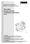
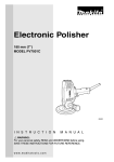
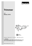
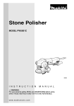
Tile Cutter
125 mm (5”)
MODEL 4101RH
003504
I N S T R U C T I O N
M A N U A L
WARNING:
For your personal safety, READ and UNDERSTAND before using.
SAVE THESE INSTRUCTIONS FOR FUTURE REFERENCE.
w w w. m a k i t a t o o l s . c o m
SPECIFICATIONS
Model
4101RH
Wheel diameter
Max. cutting capacities
125 mm (5”)
90°
41.5 mm (1-5/8”)
45°
26 mm (1”)
No load speed (RPM)
12,000/min.
Overall length
236 mm (9-1/4”)
Net weight
3.0 kg (6.6 lbs)
• Manufacturer reserves the right to change specifications without notice.
• Specifications may differ from country to country.
GENERAL SAFETY RULES
USA001-2
(For All Tools)
WARNING:
Read and understand all instructions. Failure to follow all
instructions listed below, may result in electric shock, fire and/or
serious personal injury.
SAVE THESE INSTRUCTIONS
Work Area
1. Keep your work area clean and well lit.
Cluttered benches and dark areas invite accidents.
2. Do not operate power tools in explosive
atmospheres, such as in the presence of
flammable liquids, gases, or dust. Power
tools create sparks which may ignite the dust
or fumes.
2
3. Keep bystanders, children, and visitors
away while operating a power tool. Distractions can cause you to lose control.
Electrical Safety
4. Grounded tools must be plugged into an
outlet properly installed and grounded in
accordance with all codes and ordinances. Never remove the grounding
prong or modify the plug in any way. Do
not use any adaptor plugs. Check with a
qualified electrician if you are in doubt as
to whether the outlet is properly
grounded. If the tools should electrically malfunction or break down, grounding provides a
low resistance path to carry electricity away
from the user.
5. Avoid body contact with grounded surfaces such as pipes, radiators, ranges and
refrigerators. There is an increased risk of
electric shock if your body is grounded.
6. Do not expose power tools to rain or wet
conditions. Water entering a power tool will
increase the risk of electric shock.
7. Do not abuse the cord. Never use the cord
to carry the tools or pull the plug from an
outlet. Keep cord away from heat, oil,
sharp edges or moving parts. Replace
damaged cords immediately. Damaged
cords increase the risk of electric shock.
8. When operating a power tool outside, use
an outdoor extension cord marked “W-A”
or “W”. These cords are rated for outdoor
use and reduce the risk of electric shock.
Personal Safety
9. Stay alert, watch what you are doing and
use common sense when operating a
power tool. Do not use tool while tired or
under the influence of drugs, alcohol, or
medication. A moment of inattention while
operating power tools may result in serious
personal injury.
10. Dress properly. Do not wear loose clothing or jewelry. Contain long hair. Keep
your hair, clothing, and gloves away from
moving parts. Loose clothes, jewelry, or long
hair can be caught in moving parts.
11. Avoid accidental starting. Be sure switch
is off before plugging in. Carrying tools with
your finger on the switch or plugging in tools
that have the switch on invites accidents.
12. Remove adjusting keys or wrenches
before turning the tool on. A wrench or a
key that is left attached to a rotating part of
the tool may result in personal injury.
13. Do not overreach. Keep proper footing
and balance at all times. Proper footing and
balance enables better control of the tool in
unexpected situations.
14. Use safety equipment. Always wear eye
protection. Dust mask, non-skid safety
shoes, hard hat, or hearing protection must
be used for appropriate conditions. Ordinary
eye or sun glasses are NOT eye protection.
Tool Use and Care
15. Use clamps or other practical way to
secure and support the workpiece to a
stable platform. Holding the work by hand or
against your body is unstable and may lead
to loss of control.
16. Do not force tool. Use the correct tool for
your application. The correct tool will do the
job better and safer at the rate for which it is
designed.
17. Do not use tool if switch does not turn it
on or off. Any tool that cannot be controlled
with the switch is dangerous and must be
repaired.
18. Disconnect the plug from the power
source before making any adjustments,
changing accessories, or storing the tool.
Such preventive safety measures reduce the
risk of starting the tool accidentally.
19. Store idle tools out of reach of children
and other untrained persons. Tools are
dangerous in the hands of untrained users.
20. Maintain tools with care. Keep cutting
tools sharp and clean. Properly maintained
tools with sharp cutting edges are less likely
to bind and are easier to control.
21. Check for misalignment or binding of
moving parts, breakage of parts, and any
other condition that may affect the tools
operation. If damaged, have the tool serviced before using. Many accidents are
caused by poorly maintained tools.
22. Use only accessories that are recommended by the manufacturer for your
3
model. Accessories that may be suitable for
one tool, may become hazardous when used
on another tool.
SERVICE
23. Tool service must be performed only by
qualified repair personnel. Service or main-
tenance performed by unqualified personnel
could result in a risk of injury.
24. When servicing a tool, use only identical
replacement parts. Follow instructions in
the Maintenance section of this manual.
Use of unauthorized parts or failure to follow
Maintenance instructions may create a risk of
electric shock or injury.
USE PROPER EXTENSION CORD: Use only three-wire extension cords that have threeprong grounding-type plugs and three-pole receptacles that accept the tool's plug. Make
sure your extension cord is in good condition. Replace or repair damaged or worn cord
immediately. When using an extension cord, be sure to use one heavy enough to carry the
current your product will draw. An undersized cord will cause a drop in line voltage resulting
in loss of power and overheating. Table 1 shows the correct size to use depending on cord
length and nameplate ampere rating. If in doubt, use the next heavier gage. The smaller the
gage number, the heavier the cord.
Table 1: Minimum gage for cord
Volts
120 V
Ampere Rating
More Than
Not More Than
0
6
10
12
6
10
12
16
25 ft.
Total length of cord in feet
50 ft.
100 ft.
150 ft.
AWG
18
18
16
14
16
16
16
12
16
14
14
12
14
12
Not Recommended
GROUNDING INSTRUCTIONS
This tool should be grounded while in use to protect the operator from electric shock. The
tool is equipped with a three-conductor cord and three-prong grounding type plug to fit the
proper grounding type receptacle. The green (or green and yellow) conductor in the cord is
the grounding wire. Never connect the green (or green and yellow) wire to a live terminal.
Your unit is for use on 120 volts and has a plug that looks like Fig. “A”.
4
An adapter Fig. “B” and “C” is available for connecting Fig. “A” type plugs to two-prong
receptacles. The green-colored rigid ear, lug, etc., extending from the adapter must be connected to a permanent ground, such as a properly grounded outlet box.
Adapter
Grounding Means
Cover of Grounded
Outlet Box
Grounding
Blade
Fig. A
Fig. B
SPECIFIC SAFETY RULES
Fig. C
USB071-1
DO NOT let comfort or familiarity with product (gained from
repeated use) replace strict adherence to cutter safety rules. If
you use this tool unsafely or incorrectly, you can suffer serious
personal injury.
1. DANGER! Keep hands away from cutting
area and wheel. Keep your second hand
on auxiliary handle or motor housing. If
both hands are holding the tool, they cannot
be cut by the wheel.
down on bench or floor. A coasting wheel
will cause the tool to walk backwards, cutting
whatever is in its path. Be aware of the time it
takes for the wheel to stop after switch is
released.
2. Keep your body positioned to either side
of the wheel, but not in line with the wheel.
KICKBACK could cause the tool to jump
backwards. (See “Causes and Operator Prevention of Kickback”)
5. NEVER hold piece being cut in your hands
or across your leg. It is important to support
the work properly to minimize body exposure,
wheel binding, or loss of control.
3. Do not reach underneath the work. Do not
attempt to remove cut material when wheel is
moving.
CAUTION: Wheels coast after turn off.
4. Always observe that the wheel has
stopped spinning before placing tool
6. Hold tool by insulated gripping surfaces
when performing an operation where the
cutting tool may contact hidden wiring or
its own cord. Contact with a “live” wire will
also make exposed metal parts of the tool
“live” and shock the operator.
5
7. When ripping always use a rip fence or
straight edge guide. This improves the
accuracy of cut and reduces the chance for
wheel binding.
8. Always use wheels with correct size and
shape (diamond vs. round) arbor holes.
Wheels that do not match the mounting hardware of the tool will run eccentrically, causing
loss of control.
9. Never use damaged or incorrect wheel
washers or bolts. The wheel washers and
bolt were specially designed for your tool, for
optimum performance and safety of operation.
10. Causes and Operator Prevention of Kickback:
Kickback is a sudden reaction to a pinched,
bound, or misaligned wheel, causing an
uncontrolled tool to lift up and out of the workpiece toward the operator.
When the wheel is pinched or bound tightly
by the kerf closing down, the wheel stalls and
the motor reaction drives the unit rapidly back
toward the operator.
If the wheel becomes twisted or misaligned in
the cut, the teeth at the back edge of the
wheel can dig into the top surface of the
material being cut causing the wheel to climb
out of the kerf and jump back toward the
operator.
Kickback is the result of tool misuse and/or
incorrect operating procedures or conditions
and can be avoided by taking proper precautions as given below:
Maintain a firm grip on the tool and position your body and arm to allow you to
resist KICKBACK forces. KICKBACK forces
can be controlled by the operator, if proper
precautions are taken.
When wheel is binding, or when interrupting a cut for any reason, release the trigger and hold the tool motionless in the
material until the wheel comes to a complete stop. Never attempt to remove the
tool from the work or pull the tool backward while the wheel is in motion or KICK-
6
BACK may occur. Investigate and take
corrective actions to eliminate the cause of
wheel binding.
When restarting a tool in the workpiece,
center the wheel in the kerf and check that
teeth are not engaged into the material. If
wheel is binding, it may walk up or KICKBACK from the workpiece as the tool is
restarted.
Support large panels to minimize the risk
of wheel pinching and KICKBACK. Large
panels tend to sag under their own weight.
Supports must be placed under the panel on
both sides, near the line of cut and near the
edge of the panel.
To minimize the risk of wheel pinching and
kickback. When cutting operation requires
the resting of the tool on the workpiece, the
tool shall be rested on the larger portion and
the smaller piece cut off.
Do not use dull or damaged wheel.
Unsharpened or improperly set wheels produce narrow kerf causing excessive friction,
wheel binding and KICKBACK.
Wheel depth and bevel adjusting locking
levers must be tight and secure before
making cut. If wheel adjustment shifts while
cutting, it may cause binding and KICKBACK.
Use extra caution when making a “Pocket
Cut” into existing walls or other blind
areas. The protruding wheel may cut objects
that can cause KICKBACK.
NEVER place your hand or fingers behind
the tool. If kickback occurs, the tool could
easily jump backwards over your hand, leading to serious personal injury.
11. When operating the tool, keep the cord
away from the cutting area and position it
so that it will not be caught on the workpiece during the cutting operation. Operate with proper hand support, proper
workpiece support, and supply cord routing away from the work area.
WARNING: It is important to support the
workpiece properly and to hold the tool
firmly to prevent loss of control which
could cause personal injury.
12. Use only diamond wheels. NEVER use
tool with wood cutting blades or other
sawblades. Such blades when used on
this tool frequently kick and cause loss of
control leading to personal injury.
13. Check the wheel carefully for cracks or
damage
before
operation.
Replace
cracked or damaged wheel immediately.
14. Use only flanges specified for this tool.
serious accidents, because it is extremely
dangerous.
19. Do not stop the wheel by lateral pressure
on the disc.
20. Some material contains chemicals which
may be toxic. Take caution to prevent dust
inhalation and skin contact. Follow material supplier safety data.
15. Be careful not to damage the spindle,
flanges (especially the installing surface)
or bolt. Damage to these parts could
result in wheel breakage.
21. If the plug or receptacle does get wet, DO
NOT unplug the cord. Disconnect the fuse
or circuit breaker that supplies power to
the tool. Then unplug and examine for
presence of water in the receptacle.
16. Make sure the wheel is not contacting the
workpiece before the switch is turned on.
Wait until the wheel attains full speed
before cutting.
22. WARNING: To reduce the risk of electrocution when using an extension cord,
keep ALL connections dry and off the
ground.
17. Stop operation immediately if you notice
anything abnormal.
23. Ground Fault Circuit Interrupter (GFCI)
protection should be provided on the circuit(s) or outlet(s) to be used for the tool.
Receptacles are available having built-in
GFCI protection and may be used for this
measure of safety.
18. Never attempt to cut with the tool held
upside down in a vise. This can lead to
SAVE THESE INSTRUCTIONS
WARNING:
MISUSE or failure to follow the safety rules stated in this
instruction manual may cause serious personal injury.
7
SYMBOLS
USD101-2
The followings show the symbols used for tool.
V ....................... volts
................alternating current
A ....................... amperes
n ....................no load speed
˚
Hz ..................... hertz
.../min................revolutions or reciprocation per
minute
8
FUNCTIONAL
DESCRIPTION
•
003508
1
R
T
3
CAUTION:
Always be sure that the tool is switched off and
unplugged before adjusting or checking function on the
tool.
Ground Fault Circuit Interrupter
Connect the tool to a power supply and test the Ground Fault
Circuit Interrupter (GFCI) before using the tool. Push the
RESET (R) button and confirm that the pilot lamp lights.
Push the TEST (T) button and confirm that the pilot lamp
goes out. Push the RESET (R) button again to use the tool.
2
1. RESET (R) Button
2. Pilot lamp
3. TEST (T) Button
•
003510
WARNING:
Do not use the tool if the pilot lamp does not go out when
the TEST (T) button is pushed.
Adjusting the depth of cut
Loosen the wing bolt on the depth guide and move the base
up or down. At the desired depth of cut, secure the base by
tightening the wing bolt.
1
2
1. Wing bolt
2. Base
003515
1
Bevel cutting
Loosen the wing nut on the bevel scale plate on the front of
the base. Set for the desired angle (0° - 45° ) by tilting
accordingly, then tighten the wing nut securely.
1. Wing nut
9
003516
1
Loosen the wing bolt on the depth guide and move the base
so that the end of the blade case is above the red line on the
depth guide. Then tighten the wing bolt to secure the base.
NOTE:
2
•
3
1. Wing bolt
2. End of blade case
3. Red line
003520
1
If the end of the blade case is under the red line on the
depth guide, the outer flange may hit the workpiece
when you perform the bevel cut.
Sighting
For straight cuts, align the A position on the front of the base
with your cutting line. For 45° bevel cuts, align the B position
with it.
A
2
B
1. Base
2. Top guide
003523
1
Switch action
2
•
1. Switch trigger
2. Lock-off button
10
CAUTION:
Before plugging in the tool, always check to see that the
switch trigger actuates properly and returns to the “OFF”
position when released.
To prevent the switch trigger from being accidentally pulled, a
lock-off button is provided.
To start the tool, depress the lock-off button and pull the
switch trigger. Release the switch trigger to stop.
ASSEMBLY
•
003528
CAUTION:
Always be sure that the tool is switched off and
unplugged before carrying out any work on the tool.
Installing or removing diamond wheel
Hold the outer flange with the wrench and loosen the hex
socket head bolt clockwise with the hex wrench. Then
remove the hex socket head bolt and outer flange.
2
1
1. Wrench 22
2. Hex wrench
003529
1
1.
2.
3.
4.
2
3
Inner flange
Diamond wheel
Outer flange
Hex socket head bolt
4
Install the diamond wheel, outer flange and hex socket head
bolt onto the spindle. Hold the outer flange with the wrench
and tighten the hex socket head bolt counterclockwise with
the hex wrench. BE SURE TO TIGHTEN THE HEX SOCKET
HEAD BOLT SECURELY.
•
CAUTION:
Use only the Makita wrench to install or remove the
wheel.
Pressure regulator assembly
Use the pressure regulator assembly to connect to water
source. It consists of the following parts.
Part name
Pressure regulator
Adaptor
Vinyl tube
Water pipe
Description
Preset at about 15 psi.
3/4” female hose thread (inlet) x 3/4” male hose thread (outlet)
Flow capacity: Maximum 390 GPH, minimum 10 GPH
Inlet pressures: Maximum 100 psi, minimum 25 psi.
For connecting 1/4” vinyl tube to a faucet
3/4” swivel x 1/4” adaptor
1/4” in outer diameter x 11/16” in inner diameter x 18” in length
For adjusting the amount of water flow
11
003535
1
3
4
2. Screw the pressure regulator tight on a the adaptor.
3. Connect the vinyl tube firmly to the water pipe.
5
1.
2.
3.
4.
5.
Assemble the above parts hand tight as follows.
1. Cut the vinyl tube at an angle for easier insertion. Push
the end of the vinyl tube into the end of the adaptor using
a combination pushing and twisting motion.
2
Pressure regulator assembly
Pressure regulator
Adaptor
Vinyl tube
Water pipe
003536
1
Installing water pipe
First, unplug the tool. Loosen the wing bolt on the depth
guide and move the base down. Install the water pipe on the
blade case using the screw.
2
3
1. Wing bolt
2. Blade case
3. Water pipe
003537
1
Screw the pressure regulator tight on a faucet.
Adjust the amount of water flow by simply adjusting the water
cock.
2
•
3
4
1.
2.
3.
4.
Faucet
Pressure regulator assembly
Water cock
Water pipe
12
CAUTION:
Do not connect the adaptor directly to a faucet. If you do
so, the vinyl tube may come off the water pipe during
operation.
003543
Installing cover (A)
Install the cover (A) on the tool so that its side with “Upside
” mark faces upward.
1
2
1. Clamp
2. Cover (A)
OPERATION
003545
Adjust the amount of water flow. Hold the tool firmly. Set the
base plate on the workpiece to be cut without the wheel making any contact. Then turn the tool on and wait until the
wheel attains full speed. Now simply move the tool forward
over the workpiece surface, keeping it flat and advancing
smoothly until the cutting is completed. Keep your cutting line
straight and your speed of advance uniform.
•
CAUTION:
THIS TOOL SHOULD ONLY
HORIZONTAL SURFACES.
BE
USED
ON
•
Be sure to move the tool forward in a straight line and
gently. Forcing and exerting excessive pressure or
allowing the wheel to bend, pinch or twist in the cut can
cause overheating of the motor and dangerous kickback
of the tool.
•
Since excessive cutting may cause overload of the
motor, the depth of cut should not be more than 20 mm
(13/16”) at a pass. When you wish to cut more than
20 mm (13/16”) deep, make a couple of passes with
progressively deeper settings.
MAINTENANCE
•
CAUTION:
Always be sure that the tool is switched off and
unplugged before attempting to perform inspection or
maintenance.
Dressing diamond wheel
If the cutting action of the diamond wheel begins to diminish,
use an old discarded coarse grit bench grinder wheel or con13
crete block to dress the diamond wheel. To do this, tightly
secure the bench grinder wheel or concrete block and cut in
it.
After use
Blow away dust from the inside of the tool by running the tool
at an idle for a while. Brush off accumulation of dust on the
base. Accumulation of dust in the motor or on the base may
cause a malfunction of the tool.
003543
Cleaning covers
When accumulation of dust on the cover (A) looks excessive,
loosen the clamp and remove the cover (A). Wash off accumulation of dust inside the cover (A) and wipe it. Then install
the cover (A) on the tool so that its side with “Upside
”
mark faces upward. Push the cover (A) toward the motor as
far as it will go and secure it by tightening the clamp.
1
2
1. Clamp
2. Cover (A)
003549
1
2
1. Cover (B)
2. Screw
When changing the wheel, clean the cover (B) at the same
time. Loosen the screw securing the cover (B) and remove
the cover (B). Wash off accumulation of dust inside the cover
(B) and wipe it. Then attach the cover (B) to the tool by tightening the screw. Accumulation of dust inside the covers may
cause a malfunction of the tool.
•
001145
1
CAUTION:
When using the tool, be sure to attach the covers (A)
and (B).
Replacing carbon brushes
Remove and check the carbon brushes regularly. Replace
when they wear down to the limit mark. Keep the carbon
brushes clean and free to slip in the holders. Both carbon
brushes should be replaced at the same time. Use only identical carbon brushes.
First, remove the cover (A).
1. Limit mark
14
003550
1
2
Use a screwdriver to remove the brush holder caps. Take out
the worn carbon brushes, insert the new ones and secure
the brush holder caps.
To maintain product SAFETY and RELIABILITY, repairs, any
other maintenance or adjustment should be performed by
Makita Authorized or Factory Service Centers, always using
Makita replacement parts.
1. Brush holder cap
2. Screwdriver
ACCESSORIES
•
CAUTION:
These accessories or attachments are recommended for
use with your Makita tool specified in this manual. The
use of any other accessories or attachments might
present a risk of injury to persons. Only use accessory
or attachment for its stated purpose.
If you need any assistance for more details regarding these
accessories, ask your local Makita service center.
•
Diamond wheels
•
Hex wrench 5
•
Wrench 22
•
Rip fence (guide rule)
•
Pressure regulator assembly
15
Memo
16
Cut
First-Class
Postage
Required
Post Office will
not deliver
without proper
postage.
Makita U.S.A., Inc.
14930 Northam Street
La Mirada, CA 90638-5753
Fold
17
MAIL THIS PORTION
Your answers to the following questions are appreciated.
1. This product was purchased from:
3. How did you learn about this product:
Other (
Magazine
Radio
Hardware/Lumber Store
From Dealer
Exhibition
Tool Distributor
Newspaper
From Friend
Industrial Supply
Store Display
Previous Usage
Construction Supply
Catalog
Other (
Home Center
)
2. Use of the product is intended for:
)
4. Most favored points are:
Construction Trade
Design
Repair Service
Industrial Maintenance
Features
Durability
Home Maintenance
Size
Power
Hobby
Price
Other (
Other (
)
)
Makita Brand
5. Any comments:
Paste
MODEL NO.
DAY
YEAR
SERIAL NO.
SEX
STATUS
INTL.
LAST NAME / COMPANY NAME
Married Single
M
F
STREET ADRESS
Paste
MONTH
Paste
Paste
Paste
Paste
DATE PURCHASED
Under 19
AREA
CODE
PHONE
20-29
30-39
Paste
AGE:
ZIP CODE
40-49
50-60
Over 60
Paste
Paste
STATE
Paste
CITY
Paste
Paste
BE SURE TO COMPLETE THE CUSTOMER’S PORTION OF THIS FORM AND RETAIN FOR YOUR RECORDS.
Please return this portion by facsimile or mail.
18
Facsimile No: (714) 522-8133
Paste
Paste
Paste
Paste
Paste
Paste
Paste
Paste
FACTORY SERVICE CENTERS
1-800-4-MAKITA
RETAIN THIS PORTION FOR YOUR RECORDS
ALABAMA
2365 Pelham Parkway
Pelham, AL 35124
(205) 620-1791
COLORADO
11839 E. 51st Ave.
Denver, CO 80239-2709
(303) 371-2850
KENTUCKY
1215 S. Hurstbourne Parkway
Louisville, KY 40222
(502) 326-3740
NEW MEXICO
5805 Menaul Blvd. NE
Albuquerque, NM 87110
(505) 881-4619
PUERTO RICO
200 Guayama St.
Hato Rey, PR 00917
(787) 250-8776
ARIZONA
3707 E. Broadway Rd., Ste. 6
Phoenix, AZ 85040
(602) 437-2850
CONNECTICUT
508 Spring St.
Windsor Locks, CT 06096
(860) 292-6405
LOUSIANA
5626 Jefferson Hwy.
Harahan, LA 70123
(504) 733-4138
NEW YORK
4917 Genessee Street
Cheektowaga, NY 14225
(716) 685-9503
TENNESSEE
4655 Nolensville Rd.
Nashville, TN 37211
(615) 331-9922
ARKANSAS
Shackleford Shopping Center
240 South Shackleford Rd.,
Ste. C
Little Rock, AR 72211
(501) 224-5733
FLORIDA
620 Douglas Ave. Suite 1302
Altamonte Springs, FL 32714
(407) 774-6000
MARYLAND
7541 - 45 Ritchie Highway
Glen Burnie, MD 21061
(410) 590-0160
CALIFORNIA
41850 Christy St.
Fremont, CA 94538-5107
(510) 657-9881
1421 N. Clovis Ave., Ste. 112
Fresno, CA 93727
(559) 252-5166
14930 Northam St.
La Mirada, CA 90638-5753
(714) 522-8088
1970 Fulton Avenue
Sacramento, CA 95825
(916) 482-5197
1440 South “E” Street
San Bernardino, CA 92408
(909) 885-1289
7674 Clairemont Mesa Blvd.
San Diego, CA 92111
(858) 278-4471
1714 E.McFadden Ave., Unit M
Santa Ana, CA 92705
(714) 667-5066
1565 Winchester B.
Campbell, CA 95008-0501
(408) 379-0377
16735 Saticoy St., Ste. 105
Van Nuys, CA 91406
(818) 782-2440
750 East Sample Road
Pompano Beach, FL 33064
(954) 781-6333
Thompson Center Waters
5501 W. Waters Ave., Ste. 406
Tampa, FL 33634
(813) 886-8292
GEORGIA
4680 River Green Parkway
Duluth, GA 30096-2566
(770) 476-8911
HAWAII
4510 Salt Lake Blvd., Suite A7
Honolulu, HI 96818
(808) 847-0038
ILLINOIS
1450 Feehanville Dr.
Mt. Prospect, IL 60056-6011
(847) 297-3100
INDIANA
8403 Michigan Road, Unit 1
Indianapolis, IN 46268
(317) 334-9980
KANSAS
8819 W. 95th St.
Overland Park, KS 66212
(913) 642-1111
MASSACHUSETTS
232 Providence Hwy.
Westwood, MA 02090
(617) 461-9754
MICHIGAN
37454 Ann Arbor Trail
Livonia, MI 48150
(313) 432-1012
131-35 31st Ave.
Flushing, NY 11354
(718) 886-0971
NORTH CAROLINA
3501-G S. Tryon St.
Charlotte, NC 28217
(704) 527-0611
OHIO
6253 E. Main St.
Columbus, OH 43213
(614) 860-0222
6379 Pearl Road
Parma Heights, OH 44130
(440) 843-7555
MINNESOTA
6427 Penn Ave. South
Richfield, MN 55423
(612) 869-5199
1617 E. Kemper Rd.
Sharonville, OH 45246
(513) 771-0788
MISSOURI
9876 Watson Road
St. Louis, MO 63126-2221
(314) 909-9889
OKLAHOMA
552 E. Memorial Road
Oklahoma City, OK 73114
(405) 752-2655
NEBRASKA
4129 S. 84th St.
Omaha, NE 68127
(402) 597-2925
OREGON
828 19th Avenue., N.W.
Portland, OR 97209
(503) 222-1823
NEVADA
3375 S. Decatur Blvd.
Suites. 22 - 24
Las Vegas, NV 89102
(702) 368-4277
PENNSYLVANIA
Springwater Plaza
364 Wilmington W. Chester
Pike
Glen Mills, PA 19342
(610) 459-4122
NEW JERSEY
251 Herrod Blvd.
Dayton, NJ 08810-1539
(609) 655-1212
6200 Babcock Blvd
Pittsburgh, PA 15237
(412) 366-6363
TEXAS
12801 Stemmons Fwy Ste. 809
Farmers Branch, TX 75234
(972) 243-1150
12701 Directors Dr.
Stafford, TX 77477-3701
(281) 565-8665
3453 IH-35 North, Ste. 101
San Antonio, TX 78219
(210) 228-0676
UTAH
145 E. 1300 S., Ste. 101
Salt Lake City, UT 84115
(801) 359-3410
VIRGINIA
5760 Northampton Blvd,. Ste.
102
Virginia Beach, VA 23455
(757) 460-0280
WASHINGTON
22220 84th Ave. So., Bldg. A
Kent, WA 98032
(253) 395-8055
WISCONSIN
Lincoln Plaza Shopping Ctr.
2245 S. 108th St. West Allis, WI
53227
(414) 541-4776
CUSTOMER’S RECORD
When you need service: Send
complete tool (prepaid) to one
of the Makita Factory Service
Centers listed, or to an Authorized
Makita Service Center. Be sure
to attach a letter to the outside of
the carton detailing the problem
with your tool.
Date Purchased
Dealer’s Name & Address
Model No.
Serial No.
19
WARNING
Some dust created by power sanding, sawing, grinding, drilling, and other
construction activities contains chemicals known to the State of California
to cause cancer, birth defects or other reproductive harm. Some examples
of these chemicals are:
• lead from lead-based paints,
• crystalline silica from bricks and cement and other masonry products, and
• arsenic and chromium from chemically-treated lumber.
Your risk from these exposures varies, depending on how often you do this
type of work. To reduce your exposure to these chemicals: work in a well
ventilated area, and work with approved safety equipment, such as those
dust masks that are specially designed to filter out microscopic particles.
MAKITA LIMITED ONE YEAR WARRANTY
Warranty Policy
Every Makita tool is thoroughly inspected and tested before leaving the factory. It is warranted to be free of
defects from workmanship and materials for the period of ONE YEAR from the date of original purchase.
Should any trouble develop during this one-year period, return the COMPLETE tool, freight prepaid, to one of
Makita's Factory or Authorized Service Centers. If inspection shows the trouble is caused by defective
workmanship or material, Makita will repair (or at our option, replace) without charge.
This Warranty does not apply where:
• repairs have been made or attempted by others:
• repairs are required because of normal wear and tear:
• the tool has been abused, misused or improperly maintained:
• alterations have been made to the tool.
IN NO EVENT SHALL MAKITA BE LIABLE FOR ANY INDIRECT, INCIDENTAL OR CONSEQUENTIAL
DAMAGES FROM THE SALE OR USE OF THE PRODUCT. THIS DISCLAIMER APPLIES BOTH DURING
AND AFTER THE TERM OF THIS WARRANTY.
MAKITA DISCLAIMS LIABILITY FOR ANY IMPLIED WARRANTIES, INCLUDING IMPLIED WARRANTIES OF
"MERCHANTABILITY" AND "FITNESS FOR A SPECIFIC PURPOSE," AFTER THE ONE-YEAR TERM OF
THIS WARRANTY.
This Warranty gives you specific legal rights, and you may also have other rights which vary form state to state.
Some states do not allow the exclusion or limitation of incidental or consequential damages, so the above
limitation or exclusion may not apply to you. Some states do not allow limitation on how long an implied
warranty lasts, so the above limitation may not apply to you.
Makita Corporation
3-11-8, Sumiyoshi-cho,
Anjo, Aichi 446-8502 Japan
884156D067