1
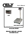
User’s Manual
VC-50
SVC-50 / MVC-50 / LVC-50
Ref.: 49-MCEVC50EN03 Rev.: 03
INDICATOR
VC-50
SVC-50 / MVC-50 / LVC-50
WEIGHING SCALES
Series VC-50 / SVC-50 / MVC-50 / LVC-50
CONTENTS
1.
INTRODUCTION .................................................................................................................................................... 1
2.
SPECIFICATIONS .................................................................................................................................................. 1
3.
INSTALATION ........................................................................................................................................................ 2
3.1.
3.2.
GENERAL INSTALATION .............................................................................................................................. 2
INSTALLATION OF SERIES SVC-50 / MVC-50 / LVC-50 ........................................................................... 2
4.
DESCRIPTION OF KEYPAD ................................................................................................................................ 3
5.
DISPLAY................................................................................................................................................................... 4
6.
OPERATION ............................................................................................................................................................ 4
6.1. MANUAL ZERO SETTING.............................................................................................................................. 4
6.2. SETTING THE TARE........................................................................................................................................ 4
6.3. SAMPLE WEIGHT............................................................................................................................................ 4
6.4. ITEM COUNTING............................................................................................................................................. 5
6.5. CHECKWEIGHER MODE................................................................................................................................ 5
6.5.1.
Operative .................................................................................................................................................... 5
6.5.2.
Setting the limits.......................................................................................................................................... 6
6.5.3.
Setting the alarm......................................................................................................................................... 6
6.6. ACCUMULATED TOTAL................................................................................................................................ 6
6.7. WEIGHING SCALES FOR ANIMALS ............................................................................................................ 6
7.
CONFIGURATION ................................................................................................................................................. 7
8.
BATTERY OPERATION........................................................................................................................................ 9
9.
INTERFACE RS-232 ............................................................................................................................................. 10
10.
CALIBRATION.................................................................................................................................................. 11
11.
ERROR CODES ................................................................................................................................................. 11
12.
TECHNICAL CONFIGURATION .................................................................................................................. 12
49-MCVC50EN03
I
USER´S MANUAL
Series VC-50 / SVC-50 / MVC-50 / LVC-50
1. INTRODUCTION
NOTE: These indicators are not allowed for the uses mentioned in paragraph 2a of the article 1st of the
Directive 90/384/CE, therefore they are not valid for commercial transactions.
Weighing scales series VC-50 / SVC-50 / MVC-50 / LVC-50 offers precise, rapid and versatile weighing for
all uses, and includes item counting and weight check.
There are 3 scales in the series in this range with a platform size that starts at 350mm x 450mm and goes up
to 600mm x 800mm, with a capacity that ranges from 30 to 600 kg.
All keypads are sealed, membrane switches are colour-marked and displays are easy-to-read, large-sized
liquid crystal displays (LCDs). The LCDs are equipped with a backlight.
All models have manual zero setting, an acoustic alarm signal for preset weights, automatic tare, preset tare,
and accumulation function that permits calculations to be stored and retrieved as a total accumulated sum.
2. SPECIFICATIONS
Model
SVC-50
MVC-50
Platform size
350mm x 450mm
420mm x 520mm
600mm x 800mm
--------------------
Range
30kg/60kg/150kg
60kg/150kg/300kg
300kg/600kg/1,000kg
--------------------
Resolution
1:15,000
Interface
RS-232 output (optional)
Stabilisation time
Normally 1 second
Operating
temperature
0°C - 40°C / 32°F - 104°F
Power supply
External CA adapter, 9V 800 mA
Calibration
External, automatic
Display
Manufacture
materials
Operating voltage
of load cell
Load cells
49-MCVC50EN03
LVC-50
VC-50
Digital 6 digit LCD display. Height of digits: 24 mm.
ABS Plastic Indicator
Max 5V/150mA
Up to four 350 ohm cells
1
USER´S MANUAL
Series VC-50 / SVC-50 / MVC-50 / LVC-50
3. INSTALATION
3.1. GENERAL INSTALATION
The platform should be placed on a firm, even surface.
Avoid extreme temperatures. Do not place the scales in direct sunlight or near air conditioning vents.
Avoid unstable tables. The tables and the ground should be firm and not vibrate. Do not place the platforms
near vibrating machinery.
Avoid unstable electricity sockets. Do not use the scales near equipment with high electrical power
consumption such as soldering equipment or large motors.
Avoid draughts such as those from fans or open doors. Do not place the scales near open windows.
Keep the indicators and the platforms clean and dry.
These indicators and platforms do not have a waterproof design (IP44) and therefore high levels of humidity
should be avoided since this can cause condensation. Avoid direct contact with water. Do not spray water on
the scales or submerge them in water. If the scales come into contact with water, measurements may
become unstable or the scales may not operate correctly. Please unplug the scales immediately from the
power supply.
Do not stack anything on the scales when they are not in use.
3.2.
INSTALLATION OF SERIES SVC-50 / MVC-50 / LVC-50
The column is attached to the base by means of a bracket that should first be secured to the body of the
base using the 4 screws supplied. The column is attached to the bracket with 2 pressure screws. The cable
that runs from the indicator module base travels inside the tube and comes out of the plastic support at the
top. Any surplus cable can be stored inside the tube.
Series SVC-50 / MVC-50 / LVC-50 comes with a stainless steel platform that is packed separately. Place the
platform on the base.
Ensure the scales are standing level, by adjusting the four feet. Adjust the scales so that the bubble in the
vial is in the centre and the scales are resting on all four feet. If the scales wobble, readjust the feet.
Place the indicator module on the column by sliding it over the bracket, and securing the edges in the base
slots. Position the cable that is in the socket base situated at the back of the indicator.
Plug in the power supply cable in the socket situated at the back of the indicator.
Make a weight calibration as shown in paragraph 9 (Calibration)
49-MCVC50EN03
2
USER´S MANUAL
Series VC-50 / SVC-50 / MVC-50 / LVC-50
Connect the load cell as indicated in the diagram below (7 pin air connector)
Pin 1
Pin 2
Pin 3
Pin 4
Pin 5
Pin 6
Pin 7
IN+
SENSE+
OUT+
OUTSENSEINNOT USED
4. DESCRIPTION OF KEYPAD
KEY
DESCRIPTION
PRIMARY FUNCTION
SECONDARY FUNCTION
Manual zero setting.
Displays shows zero.
Sets parameters and other functions.
Sets the tare of the scales, saving the
current weight in the memory as the tare
value, subtracting the value of the tare Increases the active digit when a value is
weight and displays the result. This result set for a parameter or other function.
represents the net weight. If a value is
entered using the keypad, the value will be
stored as the tare value.
Press this key in the weighing mode to
Moves the active digit to the right when
change to item counting mode. In item
setting a value for a parameter or other
counting mode, this key changes to unit
function
weight, total weight and number of items.
It changes the unit of weight.
Moves the active digit to the left when
setting a value for a parameter or other
function.
This is used to select the scale function. If Acts as a “clear” key when setting values
the scales are in weighing mode, it will for a parameter or other function.
select item count mode. If it is not in
weighing mode, it will return to this function.
This is to send data to a PC or printer using When the scales are in parameter set-up
the optional RS-232 interface. It also adds mode, press this key to return to normal
the accumulative memory value if the operation.
accumulative function is not automatic.
ON / OFF key.
49-MCVC50EN03
3
USER´S MANUAL
Series VC-50 / SVC-50 / MVC-50 / LVC-50
5. DISPLAY
The LED display will show a value and a unit to the right of the digits.
There are also three labels for TARE; GROSS weight and ZERO and for low battery,
Low battery symbol
Stability symbol
HI GROSS
OK TARE
LO ZERO
Item counting units
g/pcs
oz %
888888
tkglb
Weight control symbols
Units of weight
6. OPERATION
6.1.
MANUAL ZERO SETTING
Press
at any time in order to make a manual zero setting.. When zero is obtained, the display will show
the zero indicator.
The scales are provided with an automatic resetting function in order solve minor problems in weight
deviation or accumulation of materials on the platform. However, it may be necessary to press
reset the scales to zero if the display shows a small weight when the platform is empty.
6.2.
in order to
SETTING THE TARE
Set the scales to zero using
if necessary. The zero indicator will appear.
Place some packaging on the platform and a weight value will appear.
to set the tare of the scales. The weight that appeared on the display is saved as the tare value
Press
and that value is deducted from the display, which returns to zero. The “NET” indicator will be activated.
When a product is added, only the product weight will be shown. The scales may be tared for a second time
if another type of product is added to the first. Again, only the additional weight will be shown after the tare
has been set.
When the packaging is removed, a negative value will be shown. If the scales are tared before the packaging
is removed, this value will be the gross weight of the packaging plus all the product that was removed. the
zero indicator will also light up because the platform returns to the same situation as when
6.3.
was pressed.
SAMPLE WEIGHT
In order to determine the weight of a sample, first tare the packaging and then place the sample in the same
packaging. The display will show the weight and the unit of weight in current use.
49-MCVC50EN03
4
USER´S MANUAL
Series VC-50 / SVC-50 / MVC-50 / LVC-50
6.4.
ITEM COUNTING
When the scales show the weight, press
The scales will show "P
to initiate the item counting function.
10" , to request a sample size of 10 items. Change the sample size by pressing
. The display will move through the different options: 10, 20, 50, 100, 200 and back to 10.
-. When the number of items has been
Place the selected number of items on the platform and press
calculated, the number of items on the platform will be shown, and from then on the scales will show the
number of items that are placed on the platform.
If packaging is to be used when counting items, the empty packaging must first be tared. To do this, place
the empty packaging on the platform and press
Press
.
to return to normal weighing mode.
6.5. CHECKWEIGHER MODE
6.5.1. Operative
The checkweigher mode triggers an acoustic signal when the weight situated on the platform matches or
exceeds the values stored in the memory. The memory stores values for a upper and lower limit.
6.5.1.1.
Checkweigher modes
Weight check range:
The check of the weight is done in a range between the limits.
This sets different values for upper and lower limits where the upper value is higher than the lower value.
Weight Check Key Point:
The check of the weight is done in a exact point.
This sets the same value for the upper and lower limits.
6.5.1.2.
Options of the alarm
Mode 2 of the functioning of the alarm
For the weight check range, the display will show OK and the alarm will beep if the weight is within the two
limits.
For the weight check key point, the display will show OK and the alarm will beep if the weight matches the
limits.
Mode 3 of the functioning of the alarm
For the weight check range, the display will show OK and the alarm will beep if the weight fall outside the
limits.
For the weight check key point, the display will show OK and the alarm will beep if the weight does not match
the limits.
49-MCVC50EN03
5
USER´S MANUAL
Series VC-50 / SVC-50 / MVC-50 / LVC-50
6.5.2. Setting the limits
Press
and the display will show “F0 H-L”. Press
press
to enter. Use
or
to enter, use
to move the active digit and
value. After entering the value, press
to save and
to select “SET HI” or “SET LO”,
to change the value. Use
to delete the
to exit.
6.5.3. Setting the alarm
Press
to enter set-up mode, press
until the display shows “F4 OFF”, press
the display shows “BEEP”. Then press
to enter and
until
to select BP 2 (weight check mode 2), BP3
to save changes and
(weight check mode 3), BP1(no sound), press
to enter and
to exit.
NOTE:
The weight must be greater than 20 scale divisions for the weight control function to operate.
To deactivate the weight control function, set both limits to zero by pressing
shown. Then press
6.6.
when the current values are
to save the zero values.
ACCUMULATED TOTAL
The scales can be set to manual accumulation by pressing
. Refer to the CONFIGURATION section for
further details on selecting this method using "F5 PRT”. The accumulation function is only available when the
scales are in weighing mode. It is deactivated in item counting mode.
The weight that appears on the display will be saved in the memory if
stable.
is pressed when the weight is
The display will show “ACC 1” and the total saved in the memory will be displayed for two seconds before
returning to normal mode. If the optional RS-232 interface is installed, the weight will be sent to a printer or
PC (this type of machine does not have a print function).
Remove the weight so that the scales return to zero and put another weight on the platform. Press
the display will show “ACC 2” followed by the new total.
and
Continue until all the weights have been added.
In order to view the totals in the memory, go to the CONFIGURATION section and use the function “F1
TOL”.
6.7. WEIGHING SCALES FOR ANIMALS
The VC-50 / SVC-50 / MVC-50 / LVC-50 models can also be used as weighing scales for animals if the
external resolution is below 1/3000. To set the scales up in this mode, refer to the Technical Configuration for
VC-50 / SVC-50 / MVC-50 / LVC-50.
Place the animal on the platform. After a few seconds, if the data reading falls within the upper and lower
limits that have been set, a beep will sound to indicate that the data reading is being recorded. After the
animal has been taken off the scales, the data reading display will return to zero and the VC-50 / SVC-50 /
MVC-50 / LVC-50 will automatically perform the accumulation operation. If the mini-printer is connected, the
VC-50 / SVC-50 / MVC-50 / LVC-50 will print automatically.
To delete the accumulative memory, press
when the scales are at ZERO.
This function is only available in the animal weighing mode.
49-MCVC50EN03
6
USER´S MANUAL
Series VC-50 / SVC-50 / MVC-50 / LVC-50
7. CONFIGURATION
The scales have 6 Configuration parameters that can be set-up by the user, and there is also a method for
entering calibration mode.
To set parameters, press
.
The display will show the first function "F0 H-L". Press
Press
, to move through the other functions.
to set-up the function. It may be necessary to use
or to set a value using
to increase a digit, followed by
the active digit and then to use
leave a parameter without modifying it.
in order to enter a value. Use
to set the lower limit, or press
to go on to the next
After pressing
to set a limit, press
to change the flashing digit and then use
flashing digit. Continue with the next digit and set the amounts as required.
When all the digits have been set, press
to
to begin.
For example, when the display shows “F0 H-L”, press
The display will show “Set Lo”. Then press
parameter, "Set Hi" to set the upper limit.
in order to move
to increase the
to save the value. The display will return to the parameter that
has just been set, e.g. “Set Lo”. Continue until you reach the next parameter, where required, or press
return to normal weighing mode.
to
CONFIGURATION OF THE FUNCTIONS MENU
FUNCTION
SUB-FUNCTIONN
DESCRIPTION
F0 H-L
SEt Lo
SEt HI
to CLr
Sets the lower limit value
Sets the upper limit value
Clears the accumulated memory without printing
results
to P-C
Prints total accumulated memory and then
deletes the memory
Prints accumulated total but does not delete the
memory.
F1 toL
to Prt
F2 u nt
F3 tI
SEt dA
This determines the unit of weight that
appears on the display. Select kg, g, Lb,
etc.
Sets the date. The display will show the last
date set 00.01.01. Enter the new date in the
DEFAULT
VALUE
000.000
000.000
kilogram, kg
following format: yy.mm.dd
SEt tI
49-MCVC50EN03
Sets the time. The display will show the current
time. Enter a new time in the following format
hh.mm.ss
7
USER´S MANUAL
Series VC-50 / SVC-50 / MVC-50 / LVC-50
F4 off
Clock
Bl
Beep
F5 Prt
Determines whether the clock is on or off
Clock off
Clock on: The VC-50 / SVC-50 / MVC-50 /
LVC-50 will display the clock after 5
minutes on stand-by.
This is for setting up the backlight. It can be
set to on, automatic or off.
EL on:
EL automatic:
EL off:
This sets up the alarm mode:
1. No sound.
2. Beep within limits.
3. Beep when out of limits.
This activates the RS.232 print function
Clock
switched off
EL
automatic:
P Prt
, is pressed, P Prt.
when
O continuous printing, P Cont.
Series: RS-232 connection with the RS-232
remote display.
After setting up the printing mode
(communication), the display shows "b
xxx". The mean transfer rate must then be
to
select
set-up.
Use
600/1200/2400/4800/9600bps and after
Prog
Pin
to save.
selecting the rate, press
Access programming and calibration
menus by entering the correct password.
See section 12 Technical Configuration.
When the scales are set up to show the weight in other units of weight, the accumulation function is still
shown in kilograms
49-MCVC50EN03
8
USER´S MANUAL
Series VC-50 / SVC-50 / MVC-50 / LVC-50
8. BATTERY OPERATION
The weight indicator can operate with batteries if required. The battery will last approximately 100 hours.
When the battery needs recharging, a symbol will appear on the weight display. The battery must be
recharged when this symbol appears. The scales will continue to work for about 10 hours and then they will
shut down automatically to protect the battery.
To charge the battery, simply plug it into an electricity socket. It is not necessary to switch on the scales.
Recharge the battery for 12 hours in order to completely recharge it.
Immediately below the count display there is a LED to indicate the battery charge status. When the scales
are plugged into the mains, the internal battery will be charged. A green LED indicates that the battery is fully
charged. A red LED indicates that the battery is almost totally discharged and yellow means that the battery
is being recharged.
In the course of use, the battery may lose its capacity to be fully charged. If the battery does not last long
enough, please contact your distributor.
Note: new batteries are only partly charged. Before using the scales, insert and charge the battery following
the instructions provided below.
Some batteries will perform better after several full cycles of being charged/discharged.
Battery performance depends on many different factors, including the configuration of the backlight and
operation.
Never use a damaged battery charger or battery.
Never short-circuit the battery. An accidental short-circuit may occur if a
metallic object (coin, paper clip, ballpoint pen) makes a direct connection
between the battery’s + and – poles (the battery’s metal connectors), and
this may occur, for example, if the battery is carried in your pocket. Shortcircuiting the poles may damage the battery or the object that causes the
connection.
Do not throw batteries into fire.
Discard batteries in accordance with local policy (e.g., recycling bin).
Do not discard batteries in home rubbish bins.
Avoid charging the battery in a poorly ventilated room.
In order to maximise battery performance:
Always use original batteries and AC adaptors. The scales guarantee does
not cover damage occurring as a result of the use of any other batteries and/or chargers that are not the
originals.
The AC adapter voltage output is 9V, but normal voltage ranges from 11 to 15V.
New batteries and batteries that have been stored for a long period of time may take longer to charge.
Keep the battery at room temperature or similar temperature when charging.
Do not expose batteries to temperatures of less than -10°C or more than 45°C.
After a long time, batteries gradually lose their charge capacity and require longer charging times.
This is normal. If you charge the battery regularly and observe that the operating time is decreasing or the
charging time is increasing, it would probably be wise to purchase a new battery.
49-MCVC50EN03
9
USER´S MANUAL
Series VC-50 / SVC-50 / MVC-50 / LVC-50
9. INTERFACE RS-232
These indicators can include an optional RS-232 interface.
Specifications:
•
•
•
•
RS-232 interface for weighing data
ASCII code
8 data bits
Non-parity
Connector: 9 pin SUB-D type
•
Pin 2:
Tx
•
Pin 3:
Rx (not used)
•
Pin 5:
GND
Data format differs in normal weighing mode, item counting mode and memory total retrieval. Examples:
Normal output
GS 12.340kg
No.
1
Total 12.340kg
<lf>
<lf>
GW for gross weight, NT for net weight and unit of weight
This number increases each time a new value is stored in the memory.
Total value stored in the memory
Includes two line-feed characters
When items are counted, the unit weight and count will be printed.
GS 12,.40kg
U.W. 123.4g/pcs
PCS
100pcs
<lf>
<lf>
GW for gross weight, NT for net weight and unit of weight
The mean weight per item, calculated by the scales
Total number of items counted
Includes two line-feed characters
When the total weight stored in the accumulative memory is retrieved, the outgoing format is:
***************
<lf>
TOTAL
No.
5
Weight 21.455kg
***************
49-MCVC50EN03
Line of stars is shown
Includes line-feed character
.
10
USER´S MANUAL
Series VC-50 / SVC-50 / MVC-50 / LVC-50
10.
CALIBRATION
Switch off the indicator.
Switch them on again and during the countdown from 9 to 0, press
The display will show “CAL”. While the “CAL” is being shown, press
order to enter calibration. The display will show “noLoAd”.
Remove any weight from the platform. Press
.
,
and
in the foregoing order in
.
The display will show “LoAd”. Place the calibration weight on the scales. Press
.
. If it is
The display will show the last calibration weight used. If this weight is correct, continue by pressing
not correct, press the arrow keys to change the calibration weight value. When it is correct, press
.
If the calibration is correct the display will return to normal mode. If an error message appears, try to calibrate
the weight again since there may have been something that prevented the calibration from taking place
successfully.
If the problem continues, contact CELY or your supplier.
After calibration, the scales should be revised to check that calibration and linearity are correct. If necessary,
repeat calibration, and make sure that the scales are in a stable position before accepting any weight.
11.
ERROR CODES
ERROR
CODES
DESCRIPTION
SOLUTION
Above the range
Remove the weight from the scales.
If the problem continues, contact your distributor or CELY
for assistance.
Date set-up error
Enter the date using the correct format and logical values.
Format: yy.mm.dd
Time set-up error
Enter the time using the correct format and logical values.
Format: hh.mm.ss.
Zero set-up error
The scales were not correctly set-up in the zero range, or
-----
Err 1
Err 2
Err 4
they were switched on when was pressed .
Remove the weight from the scales and try again.
Err 6
A/D out of range
49-MCVC50EN03
to set the display to zero.
Use
If the problem continues, contact your distributor or CELY
for assistance.
The A/D converter values are out of the normal range.
Remove the weight from the scales if there is excessive
weight and check that the platform is in position.
This error may indicate that the platform or electronics may
not be working correctly.
11
USER´S MANUAL
Series VC-50 / SVC-50 / MVC-50 / LVC-50
12.
TECHNICAL CONFIGURATION
Press
when the scales are in normal weighing mode and the display will show “F0 H-L”. Press
to enter. The display will show “PIN”. Then press
the display shows “PROG” and press
to enter Technical Configuration mode and
FUNCTIÓN
P1 REF
SUB-FUNCTIÓN
AZN 0
0-AUTO
0- RANGE
Speed
to select the parameter. Press
to save and
until
and
to exit.
DESCRIPTION
This option is used to select zero tracking options.
Options: 0,5d, 1d, 2d, 4d
This option is used to select the initial zero setting range when
the indicator turns
Options: 0%, 2%, 5%, 10%, 20%
This option is used to select the manual zero range when the
ZERO key is pressed
Options: 2%, 4%, 10%, 20%, 50%, 100%
This determines the ADC speed. Press
to select the ADC
to save it.
speed and
7.5: 7.5 times per second
15: 15 times per second
30: 30 times per second
60: 60 times per second
Note: 15 or 30 times per second is recommended
P 2 CAL
DECI
INC
C AP
This option is used to select the decimal point.
Options: 0, 0.0, 0.00, 0.000, 0.0000
This option is used to select the step.
Options: 1, 2, 5, 10, 20, 50
This display shows xxxxx to set-up capacity. After selecting,
the VC-50 / SVC-50 / MVC-50 / LVC-50 will show the
parameter for animal weighing scales if the external resolution
that has been set is below 1/3000.
to select the desired
First, set the vibration range. Use
value: 0(deactivated)/5/10/15/20/25/30/35/40/45/50, vibrations
in reading data in the range that you determine. The reading
will be set.
Then set-up the reading-block option. A1 (block minimum
data), A2 (block mean data), A3 (block maximum data)
Then set-up the increase value. Press
P3 P RO
to enter data,
CAL
TRI
to save. After setting up this data, when the
and then
readings have been saved, if any items are added to the
platform or any products are removed, the reading will be
updated and saved again.
Then set-up the delay time: 50/60/70/80.
Then set-up the block conditions. 3 may be selected (the VC50 / SVC-50 / MVC-50 / LVC-50 will block reading data if it
detects reading data in a vibration range of 3 times) or 8 (it will
block if reading data is detected in a vibration range of 8
times).
Calibration, see details in section 10.
This display shows xxxxx to trimmer load cells.
COUNT
This display shows xxxxx to indicate internal counting.
RESET
This resets the original factory default set-up.
49-MCVC50EN03
12
USER´S MANUAL
Series VC-50 / SVC-50 / MVC-50 / LVC-50
DECLARATION OF CONFORMITY
Manufactures:
CELY
Type:
VC-50 / SVC-50 / MVC-50 / LVC-50 Series
The aforementioned manufacturer declares that the apparatus described herein complies with the
requirements contained in Directive 89/336/CEE and 73/23/CEE and, where applicable, to the following
harmonised regulations:
- EN55022 Class B
- EN61000-4-2
- EN61000-4-3
- EN61000-4-4
- EN60950
Ref.: 49-MCEVC50EN03
Rev.:03
02/09/05
49-MCVC50EN01
1
USER´S HANDBOOK