1
Save This Manual
For Future Reference
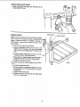
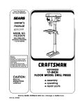
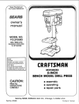
MODEL NO.
113.213213
DRILL PRESSWITH
MAXIMUM
DEVELOPED
2 HP MOTOR
Serial
Number
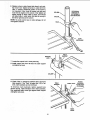
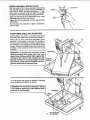
Model and serial number
may be found at the left
side of the head.
You should record both
model and serial number in
a safe place for future use.
MOTORIZED
YO
SAFETY:
READ ALL
INSTRUCTIONS
20-1NCH
iNDUSTRIAL RATED DRILL PRESS
o assembly
• operating
• repair parts
CAREFULLY
\
Sold by SEARS, ROEBUCK AND CO., Hoffman Estates, IL 60195 U.S.A.
Part No. SP5868
Printed
in China
FULL ONE YF.AR WARRANTY ON CRAFTSMAN
DRILL PRESS
if within one year from the date of purchase, this Craftsman Drill Press fails due to a defect in
material or workmanship, Sears wili repair it, free of charge.
WARRANTY SERVICE iS AVAILABLE BY SIMPLY CONTACTING THE NEAREST SEARS SERVICE CENTER/DEPARTMENT THROUGHOUT THE UNITED STATES.
This warranty applies only while this product is used in the United States.
This warranty gives you specific legal rights, and you may also have other rights which vary
from state to state.
SEARS, ROEBUCK AND CO., D/817 WA Hoffman Estates, iL 60195
GENERAL SAFETY iNSTRUCTiONS
1.
2.
3.
4.
5.
KNOW YOUR POWER TOOL
Read and understand the owner's manual and
labels affixed to the tool. Learn its application and
limitations as well as the specific potential hazards
peculiar to this tool.
GROUND ALL TOOLS
This tool is equipped with an approved 3-conductor
cord and a 3-prong grounding type plug to fit the
proper grounding type receptacle. The green conductor in the cord is the groundingwire. Never connect the green wire to a live terminal,
KEEP GUARDS IN PLACE
in working order, and in proper adjustment and
alignment.
FOR POWER TOOLS
Z87.1 ) at all times. Everyday eyeglasses are not
safety glasses. They only have impact resistant
lenses. Also, use face or dust mask ff cutting ope,_
ation is dusty, and ear protectors (pMugsor m_ffsl
during extended periods of operation.
13. SECURE WORK
Use clamps or a vise to hold work when pract_ca_ _t
frees both hands to operate tool.
14. DON'T OVERREACH
Keep proper footing and balance at all times.
15. MAINTAIN TOOLS WITH CARE
Keep tools sharp and clean for best and safest _er_
formance. Follow instructions for lubricating
anGi
changing accessories.
16. DISCONNECT TOOLS
Before servicing; when changing accessories such
as blades, bits, cutters, etc.
17. AVOID ACCIDENTAL STARTING
Make sure switch is in "OFF' position before P_Jgging in.
18. USE RECOMMENDED ACCESSORIES
Consult the owner's manual for recommended
accessories. Follow the instructionsthat accompany the accessories. The use of improper accessories may cause hazards.
19. NEVER STAND ON TOOL OR ITS STAND
Serious injurycould occur if the tool is tipped or if
the cutting tool is accidentally contacted, Do not
store materials above or near the tool such that it is
necessary to stand on the tool or its stan_ to reach
them.
20. CHECK DAMAGED PARTS
Before further use of the tool, a guard or other part
that is damaged should be carefully checked
to
ensure that it will operate properly and perform its
intended function. Check for alignment of moving
parts, binding or mowng parts, breakage of par_s,
mounting, and any other conditions that may affect
its operation. A guard or other part that is damaged
should be properly repaired or replaced.
REMOVE ADJUSTING KEYS AND WRENCHES
Form a habit of checking to see that keys and
adjusting wrenches are removed from tool before
turning it on.
KEEP WORK AREA CLEAN
Cluttered areas and benches invite accidents.
Floor must not be slippery due to wax or sawdust.
AVOID DANGEROUS ENVIRONMENT
Don't use power tools in damp or wet locations or
expose them to rain. Keep work area will lighted.
Provide adequate surrounding work space.
7. KEEP CHILDREN AWAY
All visitors should be kept a safe distance from
work area.
8. MAKE WORKSHOP CHILD-PROOF
With padlocks, master switches, by removing
starter keys, or storing tools where children can't
get them.
9. DON'T FORCE TOOL
It will do the job better and safer at the rate for
which it was designed.
10. USE RIGHTTOOL
Don't force tools or attachment to do a job it was
not designed for.
11. WEAR PROPER APPAREL
Do not wear loose clothing, gloves, neckties, or
jewelry (rings, wrist watches) to get caught in moving parts. NONSLIP footwear is recommended.
Wear protective hair covering to contain long hair.
Roll long sleeves above the elbow.
12. USE SAFETY GOGGLES (HEAD PROTECTION)
Wear safety goggles (must comply with ANSI
6.
21. DIRECTION OF FEED
Feed work into a blade or cutter against the direction of rotation of the blade or cutter only.
NEVER LEAVE TOOL RUNNING UNATTENDED
22.
Turn power off. Don't leave tool until it comes to a
complete stop.
2
additionaj
safety
SAFETY SIGNAL
WORDS
DANGER:
followed,
means
someone
if the s_fet,,
instructions
informatio_
i,:___ot
Wttl be serio(,;s_y iniured o_ ktled
&_ WARNING:
means if the safety _formatio_
s not
followed,
someone
Coutd
be ser o _s_y ir_iu_ed o_
kitted.
ir#ormat
or_ is _ot
WARNgNG: For your own safe_,, do r_ot attempt
to operate your drill press until it is completely
assembled
and installed
according
to the
instructtons.,.and
untiR you have read and understand the foNowlng:
1.
2.
3.
4.
5,
General Safety instructions
for Power Tools ....... 2
Getting to Know Your Drill Press ......................... 19
Basic Drill Press Operation ................................... 25
Adjustments ...........................................................
28
Maintenance
............................................................
30
6. Stability of Drila Press
If there is any tendency of the drill press to titt or
move during any use, boit it to the fio_:,_ror a flat pi_;<.e
of 1/2" exterior plywood _arge enough to stabiiize the
dritt press. Bolt the p{ywood to the under side of the
base, so its extends at least 2' beyond aft sides.
Make sure the plywood won't trip the operator. Do
not use pressed
wood panels ,they can break
unexpectedly.
7. Location
Use the drill press in a well Ht area and or_ a level
surface ctean and smooth enough to reduce the risk
of trips, slips, or fails. Use it where nerther the operator nor a casual observer is forced to stand in line
with a potential kickback.
8. Kickback
Kickback is the grabbing of the workpiece
by the
rotating tool. The workpiece
can be thrown at very
high speed in the direction of rotation. THiS CAN
CAUSE SERIOUS INJURY To redu_ the possibi_
of injury from kickback:
Clamp the workpiece
possible.
firmly to the table whenever
Buffing or sanding wheels
or drums should be
contacted on the side moving away from you, not
the side moving toward .you.
Use only recommended
the instructions supplied
9. Protection:
WARNING:
Eyes, Hands,
accessories
and fottow
w_th the accessory.
Face, Ears and Body.
To avoid being pulled into the
spinning tool:
1. Do NOT wear:
- gloves
- necktie
- loose c|othlng
- jewelry
2, Do tie back long hair
drill
presses
a, _f any pa_ of your driit press is missing, maifunc_
tic,,,_;_ir_q,,
_as
been
damaged or broken...such
as
the motor
s `w'itch'
or other operating control, a
safety device
or the power cord, turn the driti
press off acid
unplug
it until the particular part is
properly repaired
or replaced.
b,
CAUTION:
means if the safety
followed, someone May be iniured.
for
C,
Never place
your fingers in a position where they
c.ou_d oontz_ct
the drill or other cutting tool if the
wompiece
should
unexpectedly
shift or your hand
s;_oL._id5_ip.
i_:._avoid iniurY
from parts thrown by the spring,
foI_ow instructions
exactly as given and shown in
adjustir-_g spring
tension of quill.
_'b preve;r_t the workpiece
from being torn from
your ha_ds,
spinning
of the tool, shattering the
too_ o_ being
the'own, always properly support
you_ w_:_rk so it won't shift or bind on the tool:
Aiways
position
BACKUP
MATERIAL
(use
beneath
the workpiece)
to contact the left side
of the coturT_n.
.....Whenever
possible,
position the WORKPIECE
to contact
the left side of the column-if it is too
short or the table is tilted, clamp solidly to the
tab!e.
Use
table
slots or clamping
ledge
around the outside edge of the table.
.... When using
to the table.
a drill press VISE, always fasten it
.....Never do any work "FREEHAND" (hand-holding workpiece
rather than supporting it on the
tab_e), except
when polishing.
.. Securely lock Head to Column, table Support
to Column,
and Table to Table Support before
operating drill press.
......Nerv,
er move the Head or Table while the tool is
running.
.....Before starting
the operation, jog the motor
swit:cf_ to make sure the drill or other cutting
too! does not wobble or cause vibration.
.... if a workpiece
overhangs the table such that it
wilt fat! or tip if not held, clamp it to the table or
provide auxiliary
support.
.....Use fixtures
for unusual operations to adequatefy hold, guide and position workpiece.
..,-.Use the SPINDLE
SPEED recommended for
the specific
operation and workpiece materiaFcheck
the inside of the Belt Guard for
drifting ir_formation;
for accessories, refer to the
instructions
provided with the accessories.
e. Never climb
on the drill press Table, it could
break or pu_ the entire driUpress down on you.
f. Turn the motor
Switch Off and put away the
Sw_tch Key when leaving the drill press.
g. TO avoid }njury from thrown work or toot contact,
do NOT perform
layout, assembly, or setup work
or_the tab4e _ile
the cutting tool is rotating.
10; Use only accessories designed for this driBI
press to avoid serious injury from thrown broken parts or work pieces.
a. When cuttinglarge diameter holes:
Clamp the workpiece firmly to the table.
Otherwise the cutter may grab and spin it at high
speed.
Use only one piece, cup-type, hole cutters.
12. This Drill Press has 12 speeds as listed below:
150 RPM
1150 RPM
260 RPM
1550 RPM
300 RPM
1840 RPM
440 RPM
2220 RPM
490 RPM
2950 RPM
540 RPM
4200 RPM
See inside of belt guard for specific placement of
belt on pulleys.
DO NOT use fly cutters or mufti-part hole cutters
as they can come apart or become unbalanced in
use.
13. Think Safety. Safety is a combination of operator
common sense and alertness at all times when the
drill press is being used.
Keep speed below 1,500 RPM.
b. Drum sanders must NEVER be operated on this
drillpress at a speed greater than 1800 RPM.
c. Do not install or use any drillbit that exceeds 7" in
length or extends 6" below the check jaws. They
can suddenlybend outward or break.
d. Do not use wire wheels, router bits, shaper cutters, circle (fly) cutters or rotary planers on this
drillpress.
11. Note the Follow the Safety Warnings
and
instructions that Appear on the Panel on the
Right Side of the Head:
WARNING: Do not allow familiarity (gained from
frequent use of your drill press) to become commonplace, Always remember that a careQess
fraction of a second is sufficient to inflict severe
injury.
The operations of any power tool can result in foreign
objects being thrown into the eyes, which can result in
severe eye damage. Always wear safety goggles that
comply with ANSI Z87.1 (shown on Package) before
commencing power tool operation, Safety Goggles are
available at area stores.
WEAR YOUR
O
, WARNING
4
®
glossary of
1. Workpiece
terms
4. Revolution Per Minute {R.RM.)
The item on which the cutting operations is being
performed.
2. DriU Bit or Drill
The number of turns completed by a spinningobject
in one minute.
5, Spindle Speed
The cutting tool used in the drill press to make holes
in a workpiece.
The RPM of the spindle.
6. Backlash - The amount of handle movement or play
between adjacent moving parts.
3. Backup Material
A piece of wood placed between the workpiece and
table.,.it prevents wood in the workpiece from splintering when the drill passes through the backside of
the workpiece...also prevents drilling into the table
top.
table of contents
Page
Warranty.......................................................................... 2
General Safety Instructionsfor Power Tools.................. 2
AdditionalSafety Instructionsfor Drill Presses ..............3
Glossary of Terms........................................................... 5
Table of Contents............................................................ 5
Motor Specificationsand Electrical
Requirements............................................................. 6
Unpacking and Checking Contents ................................ 7
List of Loose Parts .......................................................... 8
Location and Function of Controls ................................. 9
Assembly ...................................................................... 10
Tools Needed ........................................................... 10
Assembly of Column and Base ............................... 10
Assembly of Elevation worm Gear and Table
Crank ...................................................................... 10
Installing the Table/Support Assembly ..................... 11
Installing the Head ................................................... 13
Mounting Motor ........................................................ 14
Installing Motor Pulley .............................................. 14
Installing and Tensioning Belt .................................. 14
Installing Belt Guard Knob ....................................... 15
Motor Connections ................................................... 16
Installing Feed Handles ........................................... 16
Installing the Chuck .................................................. 16
Installing Light Bulb .................................................. 18
Bevel Scale .............................................................. 18
Page
Getting to Know Your Drill Press .................................. 19
Spindle Speeds ........................................................ 20
Feature Description .................................................. 20
On-Off Switch ........................................................... 21
Drilling to a Specific Depth ....................................... 22
Locking Chuck Desired Depth ................................. 22
Removing the Chuck and Arbor .............................. 23
Re-Installing the Chuck and Arbor ........................... 24
Basic Drill Press Operation .......................................... 25
Installing Drill Bits in Chuck ...................................... 26
Positioning Table and Workpiece ............................ 26
Tilting Table .............................................................. 27
Hole Location ........................................................... 27
Feeding .................................................................... 27
Adjustments .................................................................. 28
Quill Return Spring ................................................... 28
Quill Bearing Adjustment ......................................... 29
Maintenance ................................................................. 30
Lubrication .................................................................... 30
Recommended Accessories ........................................ 30
Trouble Shooting .......................................................... 31
Repair Parts .................................................................. 32
5
motor specifications and electrical requirements
MOTOR SPECiFiCATiONS
This drill press is designed to use a 1725 RPM motor
only. Do not use any motor that runs faster than 1725
RPM. It is wired for operation on 110-120 volts, 60 Hz.
alternating current.
WARNING: To avoid injury from unexpected
startup, do not use blower or washing machine
motors or any motor with an automatic reset
overload protector.
CONNECTING TO POWER
SOURCE OUTLET
This machine must be grounded while in use to protect
the operator from electric shock.
Plug power cord into a 110-120V properly grounded
type outlet protected by a 15-amp, dual element time
delay fuse or circuit breaker.
NOT ALL OUTLETS ARE PROPERLY GROUNDED.
IF YOU ARE NOT SURE THAT YOUR OUTLET, AS
PICTURED BELOW, IS PROPERLY GROUNDED,
HAVE iT CHECKED BY A QUAUFIED ELECTRICIAN.
WARNING: To avoid electric shock, do not
touch the metal prongs on the plug, when
installing or removing the plug to or from the
outlet.
This power tool is equipped .with a 3-conductor cord
and grounding type plug, approved by Underwriters'
Laboratories and the Canadian Standards Association.
The ground conductor has a green jacket and is
attached to the tool housing at one end and to the
ground prong in the attachment plug at the other end.
This plug requires a mating 3-conductor grounded type
outlet as shown.
ff the outlet you are planning to use for this power tool
is of the two prong type, DO NOT REMOVE OR
ALTER THE GROUNDING PRONG IN ANY MANNER.
Use an adapter as shown and always connect the
grounding lug to known ground.
It is recommended that you have a qualified electrician
replace the TWO prong outlet with a properly grounded
THREE prong outlet.
An adapter as shown below is available for connecting
plugs to 2-prong receptacles
WARNING: The green grounding lug extending
from the adapter must be connected to a permanent ground such as to a properly grounded
outlet box.
GROUNDING LUG
SCREW
3-PRONG
WARNING: Failure to properly ground this
power tool can cause electrocution or serious
shock, particularly when used in damp locations, or near metal plumbing, if shocked, your
reaction could cause your hands to hit the cutting tool.
If power cord is worn or cut, or damaged in any
way, have it replaced immediately
to avoid
shock or fire hazard.
3-PRONG
PLUG
__\
_
MAKE SURE THIS IS
RECEPT.CLE
ADAPTER
NOTE: The adapter illustrated is for use only if you
already have a propedygrounded 2-prong receptacle.
NOTE: Make sure the proper extension cord is used
and is in good condition.
The use of any extension cord will cause some loss of
power. To keep this to a minimum and to prevent overheating and motor burn-out, use the table below to
determine the minimum wire size (A.W,G.) extension
cord. Use only 3 wire extension cords which have 3prong grounding type plugs and 3-pole receptacles
which accept the tools plug.
GROUNDING
PRONG
ALWAYSUSE A
PROPERLYGROUNDED
OUTLET
Your unit isfor use on 120 volts, it has a plug that looks
like the one above.
Extension Cord Length
0-25 Feet
26-50 Feet
Wire Size A.W.G.
16
14
WARNING: To avoid injury from unexpected
starting or electrical shock, do not plug the
power cord into a source of power. This cord
must remain unplugged
whenever you are
working on the drill press.
Model 113.213213 Drill Press is shipped complete in
one box.
1. Unpacking and Checking Contents
a. Separate all "loose parts" from packaging materials and check each item with "Table of Loose
Parts" to make sure all items are accounted for,
before discarding any packing material. Some
loose parts are contained inside the belt guard.
Open the belt guard cover to find them.
WARNING: if any parts are missing,
do not
attempt to assembDe drill press, plug in the
power cord, or turn the switch on until the
missing parts are obtained and are installed
correctly.
2. Remove the protective oil that is applied to the table
and column. Use any ordinary household type
grease and spot remover.
G
E
WARNING: To avoid fire or toxic reaction, never
use gasoline, naptha or simiSar highly volaUle
solvents to remove protective oil.
3. Apply a coat of paste wax to the table and column to
prevent rust. Wipe all parts thoroughly with a clean
dry cloth.
TABLE OF LOOSE
Rtem
A
B
C
D
E
F
G
H
Part Name
PARTS
Qty.
Table/Support Asrn ............................................ 1
Column Support Asm ........................................ 1
Owner's Manual ................................................. 1
Motor .................................................................. 1
Box of Loose Parts ............................................. *
Base ................................................................... 1
Head Asm .......................................................... 1
Bag of Loose Parts ............................................ 1
* Number varies; bags can contain other smaller bags.
Note: To make assembly easier keep contents of each
bag together and separate from contents of other bags.
List of loose parts in the box and bags
M8 x 1.25-20 Long
Clamp-column Lock (1)
Hex head bolt (4)
M12 x 1.75 - 40 Long
Hex head bolt (4)
nk (With Set Screw) (1)
M5
0.8 - screw
12 Long
Panxhead
(1)
Handle crank (1)
Flat washer ,(8)
M8x16x1.6
(_
e (3)
Q
M8 x 1.25 hex nut (4)
(_p
M3 Hex "L" wrench (1)
Key chuck (1)
M4 Hex "L" wrench (1)
M5 Hex "L" Wrench (1)
(_
__
Chuck (1)
_
Pulley-motor (With Set Screw) (1)
M6 Hex "1_"Wrench (1)
Elevation Worm
Gear Shaft (1)
Idler Pulley Assembly (1)
_
Key-Dritt (1)
Knob (1)
Belt '_" A29 (1)
Belt "V" A33 (1)
J
__=
Key-switch (1)
location
It
and function
BELT TENSION LOCK HANDLES...Tightening
handles locks motor bracket support and BELT
TENSION HANDLE to maintain correct belt distance and tension.
2.
BELT TENSION HANDLE...Turn handle counter
clockwise to apply tension to belt, turn handle
clockwise to release belt tension.
3.
HEAD LOCK SET SCREWS...Lock the head to
the column. ALWAYS have them locked in place
while operating the drill press.
4.
5.
FEED HANDLE...For
moving the chuck up or
down. One or two of the handles may be removed
if necessary whenever the workpiece is of such
unusual shape that it interferes with the handles.
TABLE CRANK...Tum clockwise to elevate table.
Support lock must be released before operating
crank.
6.
CHUCK KEY...Used to tighten drill in the chuck
and also to loosen the chuck for drill removal.
7.
CHUCK...Holds drill bit or other recommended
accessory to perform desired operations.
8.
DEPTH SCALE...AIIows operator to adjust drill
press to drill to a desired depth.
of controls
9. DRILL "ON-OFF" SWITCH...Tums drill press on
and off...also used to lock drill press in off position.
10. UGHT "ON=OFF" SWITCH...Turns
and off.
the light on
11. DEPTH SCALE LOCK...Locks the depth scale at
selected depth.
12. SPRING CAP...Provides
spring tension.
means to adjust quill
13. TABLE LOCK PIN...Acts as an indexing pin to
locate the table at a 90 ° angle to the drill and
chuck.
14. TABLE BEVEL LOCK...Locks the table in any
position from 0o-45°.
15. BEVEL SCALE...Shows degree table is tilted for
bevel operations. Scale is mounted on side of arm.
18. SUPPORT LOCK..,Tightening locks table support
to column. Always have it locked in place while
operating the Drill Press.
11
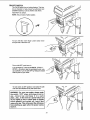
assembUy
COMBINATION SQUARE MUST BE TRUE.
WARNING: For your own safety, never connect
[ plug to power source outlet until all assembly
Check its accuracy as illustrated below.
STRAIGHT EDGE OF
BOARD 3/4" THICKTHIS EDGE MUST BE
PERFECTLY STRAIGHT
_ steps are completed.
-
DRAW LIGHT
LiNE OH BOARD
ALONG
TOOLS NEEDED
MEDIUM
SCREWDRIVER
F
COMBINATION
SQUARE
8-INCH ADJUSTABLE
WRENCH
SHOULD BE
OVERLAP WHEN
SQUARE IF FLAPPED OVER IN DOTTED POSITION
i
table, To
or drill
press
from
carton.
I base,
WARNING:
avoid
backhead
injury,
get the
help
to lift the
ASSEMBLY
!
OF BASE/COLUMN
12rnm DIA:X 40turn LONG BOLT
1. Positionbase on floor.
2_ Remove protective sleeve from column tube and discard. Place column assembly on base, and align
holes in column support with holes in base.
COLUMN
SUPPORT
3. Locate four (4) 12mm Dia. x 40mm long bolts among
loose parts bag.
4. Install a bolt in each hole through column support
and base and tighten with adjustable wrench.
ASSEMBLY
OF ELEVATION WORM GEAR AND TABLE CRANK
1. Find elevation worm gear shaft, the crank handle
and table crank in the loose parts bag. Insert the elevation shaft into the table support and extend the
shaft through the opening as far as possible. The
crank is to be installed on the elevation worm gear
shaft, the set screw is to be aligned with the fiat portion of the shaft. The crank is to be positioned as
close to the arm support as possible, then tighten set
screw with a 3mm HEX "L" wrench. See illustration.
._
GEAR SHAFT
ELEVATION WORM
TABLE
2. Screw the crank handle into the table crank as illustrated. Use an adjustable wrench to tighten the crank
handle securely.
10
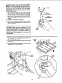
TABLE SUPPORT
ASSEMBLY
INSTALLATION OF TABLE/SUPPORT
ASSEMBLY AND HARDWARE
COLLAR
3. Loosen set screw in column collar with 3mm HEX "L"
wrench and remove collar and rack from column.
,,.°
w
0°, !
4. With long smooth end of rack pointing upward, slide
rack down through large round opening in table support. Engage rack in gear mechanism found inside
opening of table support.
SPECIAL NOTE: This step can be made easier to
complete if you remove the table from the table support. To do so, following the instructions listed under the
heading "bevel scale" in this section of the manual and
remove the table lock pin and table bevel lock.
,i
TABLE
5. While holding rack and table support in an engaged
position slide both down over column. Slide rack
down column until rack is positioned against lower
column support.
COLUMN
RACK
TABLE
SUPPORT
LOWER
sCOLUMN
TABLE
SUPPORT
ASSEMBLY
11
UPPORT
6. Replace column collar (bevel side down) and position it over rack. Tighten set screw in collar with 3mrn
HEX %" wrench. Rotational position of set screw is
not important. Collar must sit loosely over rack and
must not be angled on the column. Only tighten set
screw enough to keep collar in place; rack should
still slide freely in collar when the table is swung to
the left or right around the column.
ROTATIONAL
POSITION OF
SET SCREW IS
NOT IMPORTANT
COLLAR
NOTE: To avoid column tube or collar damage, do not
over tighten setscrew.
RACK
GEAR
MECHANISM
TABLE
SUPPORT
SUPPORT
LOCK
7. Locate the supportlock in loose parts bag.
8. Install support lock from left side into table support
and tighten by hand.
COLUMN
9. Check "Gap" or clearance between table crank and
table support. If the "Gap" is larger than 1/32 of an
inch, crank backlashcan be minimized.
TABLE
SUPPORT
To minimize crank backlash, tighten support lock
(shown above), rotate elevation worm shaft clockwise,
then assemble table crank tight against table support
and tighten set screw.
CHECK"GAP"
\
TABLE
CRANK
12
ROTATE
ELEVATION
WORM SHAFT
CLOCKWISE
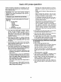
iNSTALLiNG
THE HF_AD
CAUTION: To avoid back injury, get help in lifting the head.
....
.L
1. Remove protective bag from head assembly and discard. Carefully lift head above column tube and slide
it onto column making sure head slides down over
column as far as possible. Align head with table and
base.
2. Using a 5mm HEX "L" wrench, tighten the two head
lock set screws on the right side of the head.
HEAD
LOCK
SET
SCREWS
13
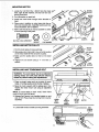
MOUNTING
MOTOR
MOTOR
BRACKET
1. Locate four (4) 8mm Dia. x 20mm long hex head y
bolts, eight (8) flat washers, and four (4) hex nuts
among loose parts.
2. Put a fiat washer on each bolt.
MOTOR
BASE
3. Install hex head bolts through motor bracket on
head.
4. Place motor in position so motor base slots line up
with motor bracket slots. Install fiat washers and hex
nuts as illustrated. (Do not tighten)
5. Motor shaft should be as close as possible to center
of round opening in belt guard.
8mm Dia.x 2_m LONGBOLT
INSTALLING
FLAT
WASHER
BOLT
HEXNUT
HEX
NUT
FLAT WASHER
MOTOR PULLEY
MOTOR
PULLEY
1. Find the motor pulley in loose parts bag.
2. Slide pulley onto motor shaft. Line up the flat surface
on the motor shaft with the set screw in pulley.
SET SCREW
3. Make sure the pulley does not rest on the lower
guard.
4. Tighten the set screw using a "4" mm Hex "L"
wrench.
FLAT
SURFACE
_
INSTALUNG
AND TENSIONING
STRAIGHT EDGE
BELT
WARNING: To avoid injury due to accidental
starting always turn drill press off and remove
switch key before making belt adjustments.
1. Place a straight edge such as a piece of wood,
metal, or framing square across the top of pulleys.
t,
2
0001
2. Move the motor upward until the pulleys are in line.
"13ghtenthe motor mount nuts using an adjustable
wrench.
NOTE: To avoid rattles or other noise, motor frame
must not touch lower belt guard.
3. Release Belt Tension Lock handles located on each
side of Drill Press head by turning them counterclockwise.
LOWER
BELT
BELT
TENSION
MOTOR
MOUNT
GUARD
LOCK
HANDLE
NUTS
•
4. Loosen Belt Tension handle by turning clockwise.
'_'
MQTQR
BELT
HANDLE
"__i
]
TENSION
5. Locate idler pulley assembly in loose parts bag and
place in proper hole.
j
_y
IDLER PULLEY ASSEMBLY
SPINDLE PULLEY
6.
Locate two (2) V-belts in the loose parts bag.
7.
Use speed chart inside belt guard to choose speed
for drilling operation. Install belts in correct position
for desired speed. The longer of the two belts is
always positioned between the spindle pulley and
idler pulley.
NOTE: Refer to chart inside
Recommended Drilling Speeds.
belt
guard
for
8.
Apply tension to belt by turning Belt Tension Handle
counter clockwise until belt deflects approximately
1/2 inch by thumb pressure at its center.
9.
Tighten Belt Tension Lock Handles.
IDLER PULLEY
NOTE: Over tensioning belt may cause motor not to
start or damage bearings.
BELT
TENSION
10. If belt slips while drilling, readjust belt ten sion.
(} LOCK HANDLE
BELT
TENSION
HANDLE
BELT GUARD KNOB _"_J
BELT GUARD KNOB
INSTALLING
SCREW
BELT GUARD KNOB
1. To attach belt guard knob, locate knob and 5mm Dia.
x 12mm long pan hd. screw in loose parts bag.
Install screw _n hole located in guard and attach
knob turning until tight.
WARNING: To avoid possible injury keep guard
in place and in proper working order while
operating.
15
I
I
MOTOR CONNECTIONS
plug to power source outlet until ag assembly
steps are completed.
-/U((((
1, Open motor connector box cover located on underside of motor using flat blade screwdriver.
- CE.TER
sT.*,.
-tt'_\\\
\'k._
J]_'l_
_
_"1
_ _
_
RELIEF GROOVE
F'_
\-""
TO TERMINAL #4
WARNING: To avoid electrocution, never connect anything but the ground wire (colored
green) to the green screw.
2. Remove GREEN SCREW and insert through round
metal terminal on the end of the GREEN wire of
power cord.
3. Reinsert GREEN SCREW in threaded hole that it
was removed from and tighten securely,
BLACK
4. Insert terminal end of WHITE wire on spade terminal
POWER
(next to silver _
marked #4 on the motor. Push
terminal firmly until seated.
5. Insert terminal end of BLACK wire on spade terminal
(next to copper gp__) marked #1 on the motor. Push
terminal firmly until seated.
MOTOR
}LACK
CORD
GREEN
GROUND
6. Close motor connector box being sure that power
cord is seated in the "center" strain relief groove and
tighten box cover screws.
7, Do not plug in power cable.
i
f
1. Locate three (3)feed handles arnong loose parts.
_
_,_,_,,_,
2 Screw the feed handles into the threaded holes in
/
_,,_
/_-'_
FEED
HANDLE
i
INSTALUNG
THE CHUCK
1. Clean out the TAPERED HOLE in the chuck, Clean
the tapered surface on the arbor with a clean cloth,
Make sure there are no foreign particles sticking to
these surfaces. The slightest piece of dirt on these
surfaces will prevent the chuck from seating properly. This will cause the drill to '_Nobble" or possibly fall
off when drilling.
QUILL
ARBOR
CLEAN THIS
SURFACE
16
2. Slide the chuck up over the arbor as illustrated.
LL
3, Unlock support lock and raise table so its about two
(2) inches below tip of chuck.
SUPPORT
LOCK
4. Turn chuck sleeve clockwise and open jaws in chuck
completely.
5. Turn feed handles counterclockwise and force chuck
against table until chuck is secure.
\ql
CHUCK
SLEEVE
_iP
OFCHUCK
17
iNSTALLiNG
UGHT BULB
1. install a light bulb (not larger than 60 watt) into the
socket insidethe head.
BEVEL SCALE
BEVEL SCALE
TABLE SUPPORT
NOTE: The bevel scale has been included to provide a
|
quick method for beveling the table to approximate ZE
angles. If precise accuracy is necessary, a square, or UNE_
other precision measuring tool should be used to position the table.
.ol
TABLE
BEVEL
LOCK
1. To use the bevel scale do the following.
a. Using an adjustable wrench, turn the nut (on the
table lock pin) clockwise. This will pull the table
lock pin out of its indexing hole in the table support.
b. Lcosen the table bevel lock by turning it counterclockwise using an adjustable wrench.
c. Move table so desired angle on bevel scale is
straight across from zero line on table support,
d. Retighten the table bevel lock,
2. To return the table to the 90° position do the following:
a. Loosen the table bevel lock,
b. Move the table and reinstall the table lock pin into
the indexing hole in the table support, Tap in gently into place.
c. Tighten the table bevel lock,
d. Tighten the nut (on the table lock pin) finger tight
so it won't vibrate loose.
18
LOCK
PIN
TABLE
geeing to know your dritmpress
27
FEED SPRING
ADJUSTMENT
26
FEED SPRING
20
SPRING
CAP
1
BELT GUARD
\
3
SWITCH
BELT TENSION
LOCK HANDLE
2
DRILL
SPEED CHART
25
18
TABLE BEVEL LOCK
3
BELT TENSION
LOCK HANDLE
4
23
BELT TENSION
HANDLE
BEVEL
22
17
5
DEPTH
SCALE LOCK
HEAD LOCKS
6
16
TABLE
LOCK PIN
FEED HANDLE
DEPTH SCALE
INDICATOR
7
COLUMN COLLAR
SPINDLE
SPLINES
(GROOVES)
WEDGE KEY
15
DEPTH SCALE
14
COLUMN
RACK
R
(TEETH)
ACK
13
19
CHUCK KEY
ARBOR
\
18
CHUCK
QUILL AND SPINDLE ASSEMBLY
INSIDE OF DRILL PRESS
19
COLUMN
I
/.4
9
ITABLECRANK
!
This Drill Press has 12
150 RPM
260 RPM
300 RPM
440 RPM
speeds as listed
49(] RPM
540 RPM
1150 RPM
1550 RPM
below:
1840
2220
2950
4200
See inside of belt guard for specific placement of belts
on pulleys
RPM
RPM
RPM
RPM
SPINDLE SPEEDS IN R,P.N.
150
260
3O(}
440
490
540
1150
1550
1840
2220
2950
4200
Feature Description
1. BELT GUARD ASSEMBLY...Covers pulleys and
belt during operation of drill press.
2. DRILLING SPEED CHART...Speeds
can be
changed by placing the belt in any of the STEPS
(grooves) in the pulleys. See Spindle Speed label
inside belt guard. To determine the approximate
drilling speed, for specific materials, refer to the
table insidethe belt guard.
13. TABLE...Provides
working surface to support
workpiece.
14. COLUMN...Connects head, table, and base on a
one-piece tube for easy alignmentand movement.
15. DEPTH
drilled.
depth of hole being
16. DEPTH SCALE INDICATOR...Indicates drilling
depth selected on depth scale,
17. DEPTH SCALE LOCK...Locks the depth scale to
selected depth.
18. CHUCK...Holds drill bit or other recommended
accessory to perform desired operations.
3. BELT TENSION LOCK HANDLES...Tightening
handles locks motor bracket support and BELT
TENSION HANDLE to maintain correct belt distance and tension.
4. BELT TENSION HANDLE...Turn handle counter
clockwise to apply tension to belt, turn handle
clockwise to release belt tension. Refer to section
"Assembly-Installing and Tensioning Belt",
5. HEAD LOCK...Lock the head to the column.
ALWAYS have them locked in place while operatingthe drillpress.
6. FEED HANDLE...For moving the chuck up or
down. One or two of the handles may be removed
if necessary whenever the workpiece is of such
unusual shape that it interferes with the handles.
7. COLUMN COLLAR...Holds the rack to the column. Rack remains movable in collar to permit
table support movements.
So
TABLE SUPPORT...Rides on column to support
arm and table.
19. CHUCK KEY...It isa self-ejectingchuck key which
will "pop" out of the chuck when you let go of it.
This action is designed to help prevent throwingof
the chuck key from the chuck when power is
turned "ON". Do not use any other key as a substitute, order a new one if damaged of lost.
20. SPRING CAP...Provides means to adjust quill
springtension.
21. DRILL "ON-OFF" SWITCH...Has locking feature.
THIS FEATURE IS INTENDED TO HELP PREVENT UNAUTHORIZED AND POSSIBLE HAZARDOUS USE BY CHILDREN AND OTHERS.
22. TABLE LOCK PIN...Acts as an indexing pin to
locate the table at a 90 ° angle to the drill and
chuck.
23. BEVEL SCALE...Shows degree table is tilted for
bevel operations,Scale is mounted on top of arm.
24. SUPPORT LOCK...Tightening locks table support
to column. Always have it locked in place while
operating the Drill Press.
25, TABLE BEVEL LOCK...Locks the table in any
position from 00-45 °.
26. FEED SPRING...Provides tension to feed handle
mechanism.
9. TABLE CRANK...Turn clockwise to elevate table.
Support lock must be released before operating
crank.
10. BASE...Supports Drill Press. For additional stability, holes are provided in base to bolt Drill Press to
floor. (See "Additional Safety instructions for Drill
Presses.")
11. COLUMN SUPPORT...Supports column, guides
rack, and provides mounting holes for column to
base.
12. RACK...Combines with gear mechanism to provide easy elevation of table by hand operated table
crank.
SCALE._Shows
27, FEED SPRING ADJUSTMENT...AIIows
adjustment of tension to feed handle mechanism.
2O
ON-OFF SWITCH
The On-Off switch has a locking feature. This feature is intended to help prevent unauthorized and
possible hazardous use by children and others.
Insert KEY into switch.
NOTE: Key is made of yellow plastic.
To turn drill ON, insert finger under switch lever
and pull end of the lever out.
To turn drill OFF, push lever in.
In an emergency: If the drill bit BINDS...STALLS...
STOPS...or tends to tear the workpiece Ioose...you
can QUICKLY turn the drill OFF by hitting the switch
with the palm of your hand.
To lock switch in OFF position, hold switch IN with
one hand and REMOVE key with other hand.
WARNING: For your own safety, always push
the switch "OFF" when drill press is not in
use...remove
key and keep it in a safe
place...aiso...in the event of a power failure (all
of your lights go out) or blown fuse or tripped
circuit breaker, turn switch off...Iock it and
remove the key. This will prevent the drill press
from starting up again when the power comes
back on.
21
DRiLLiNG TO A SPECiFiC
DEPTH
To drifta BLIND hole (not all the way through)to a given
depth,proceed as follows.
1. Mark the depth of the hole on the side of the workpiece.
2. Loosen the depth scale lock.
3. With the switch OFF, bring the drillbit down untilthe
tip or lips of the bit are even with the mark.
DEPTH
SCALE LOCK
4. -rum the depth scale counterclockwise until it stops
moving.
5. Tighten the depth scale lock.
DEPTH SCALE
INDICATOR
6. The bit will now be stopped at this depth until the
depth scale is readjusted.
DEPTH
SCALE
MARK
ANOTHER
WAY-
DEPTH SCALE
1. Wdh the switchOFF, loosen the depthscale lock.
\
2. Place workpiece on table. Adjust table until tip of drill
bit is just a littleabove the top ofthe workpiece. Turn
the depth scale clockwiseto zero.
3. rum the depth scale clockwise until the depth scale
indicator points to the desired drilling depth on the
depth scale.
DEPTH
SCALE LOCK
4. Tighten the depth scale lock.
SCALE
5. The chuck or drill will now be stopped after traveling
downward the distance selected on the depth scale.
DEPTH SCALE
INDICATOR
LOCKING CHUCK AT DESIRED DEPTH
ADJUST TO
1. With the switch off-loosen the depth scale lock.
2. Turn the feed handles until the chuck is at the
desired depth. Hold feed handles at this position,
DESIRED DEPTH/
3. Turn the depth scale clockwise until it stops.
4. Tighten the depth scale lock,
5. The chuck will now be held at this depth when the
feed handles are released,
22
/
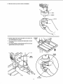
REMOVmNG CHUCK AND ARBOR
SPINDLE KEY
I. With the switch OFF, adjust depth scale to hold drill
at a depth of (3) three inches. (See instructionsfor
"Locking chuck at desired depth").
2. Align key holes in spindle and quill by rotating the
chuck by hand. (See illustration)
HOLE __
QUILL KL=Y_
-
3. Insert key drift into key holes.
HOLE
4. Tap key drift lightly until the chuck and arbor fall out
of spindle.
NOTE: Place one hand below chuck to catch it when it
falls out.
CHUCK
SLEEVE
SPECIAL
NOTE: With the chuck and arbor
removed, morse taper number 3 drills may be used
by installing one directly into the spindae in the
same position normalhj occupied by the arbor.
The same procedures and cautions used when
"reinstalling
the arbor and chuck" (see following
page) should be used when installing a morse taper
number 3 driBi. The only exception to this procedure is that you may place a piece of wood on the
table top to prevent damage to the table and dri,,
when they are forced against each other.
DRIFT
KEY
CHUCK
SLEEVE
J
CHUCK
BODY
23
RE-INSTALUNG
THE CHUCK AND ARBOR
NOTE: The chuck received with this drill press will not
permitthe use of smaller diameter drillbits. For an alternate accessory chuck and key with 1/32" - 5/8" capacity
the following part number shouldbe ordered. - Part No.
#8! 7340 (chuck & key).
1. Clean the tapered surfaces on the arbor and spindle
with a clean cloth. Make sure there are no foreign
particles sticking to these surfaces. The slightest
piece of dirt on these surfaces will prevent the arbor
from seating properly. This will cause the drill to
"wobble".
TAPERED SLIRFACE
TAPERED
ARBOR SURFACE
2. Slide arbor into spindle on drill press.
3. Push up on chuck/arbor assembly as you rotate
them. You willfeel rectangular end of arbor slip intoa
notch in the spindle.
CHUCK
SLEEVE
WARNING: Make sure the rectangular end of
the arbor has slipped into the notch in the
spindle before going on to step 4. Failure to
follow this direction may allow the chuck to
come loose during operation, fly' out, and hit
the operator.
CHUCK
BODY
4. Unlock support lock and raise table so its about two
(2) inches below tip of chuck.
5, Turn chuck sleeve clockwise and open jaws in chuck
completely.
6, "rum feed handles counterclockwise and force chuck
against table until arbor is secure.
SUPPORT
LOCK
_POF
CHUCK
FEED
HANDLE
CHUCK
SLEEVE
CHUCK
24
basic drill press operation
Follow the following instructions for operating your drill
press to get the best results and to minimize the likelihood of personal injury.
-
Securely lock Head and Support to Column,
and table to support before operating drill
press.
Never move the Head or Table while the tool is
running.
WARNING:
For your own safety, always
observe the safety precautions here and on
pages 2, 3, and 4.
I. Protection: Eyes, Hands Face, Ears & Body
WARNING: To avoid being pulled into the spinning tool1. Do NOT wear:
- gloves
- necktie
b.
c.
d.
If any part of your drill press is missing, malfunctioning, has been damaged or broken...such as
the motor switch, or other operating control, a
safety device or the power cord...cease operating
immediately until the particular part is properly
repaired or replaced.
Never place your fingers in a position where they
could contact the drill or other cutting tool if the
workpiece should unexpectedly shift or your hand
should slip.
To avoid injury from parts thrown by the spring,
follow instructions exactly as given and shown in
adjusting spring tension of quill.
To prevent the workpiece from being torn from
your hands, spinning of the tool, shattering the
tool or being thrown, always properly support your
work so it won't shift or bind on the tool:
-
-
If a workpiece overhangs the table such that it
will fall or tip if not held, clamp it to the table or
provide auxiliary support.
-
Use fixtures for unusual operations to adequately hold, guide and position workpiece.
Use the SPINDLE SPEED recommended for
the specific
operation
and workpiece
material-check
the panel inside the guard
cover for drilling information; for accessories,
refer to the instructions provided with the
accessories.
e. Never climb on the drill press Table, it could break
or pull the entire drill press down on you.
f. Turn the motor Switch Off and put away the
Switch Key when leaving the drill press.
g. To avoid injury from thrown work or tool contact,
do NOT perform layout, assembly, or setup work
on the table while the Cuttingtool is rotating.
2. Use only accessories designed for this drill press
to avoid serious injury from thrown broken parts
or work pieces.
a. When cutting large diameter holes:
Clamp the workpiece firmly to the table. Otherwise
the cutter may grab and spin it at high speed.
Use only one piece, cup-type, hole cutters.
DO NOT use fly cutters or multi-part hole cutters
as they can come apart or become unbalanced in
use.
Always position BACKUP MATERIAL (use
beneath the workpiece) to contact the left side
of the column.
Keep speed below 1,500 RPM.
b. Drum sanders must NEVER be operated on this
drill press at a speed greater than 1800 RPM.
c. Do not install or use any drill that exceeds 7" in
length or extends 6" below the chuck jaws. They
can suddenly bend outward or break.
d. Do not use wire wheels, router bits, shaper cutters, circle (fly) cutters or rotary planers on the drill
press.
-
Whenever possible, position the WORKPIECE
to contact the left side of the column-if it is too
short or the table is tilted, clamp solidly to the
table. Use table slots or clamping ledge around
the outside edge of the table.
- When using a drill press VICE, always fasten it
to a table.
-
Before starting the operation, jog the motor
switch to make sure the drill or other cutting
tool does not wobble or cause vibration.
-
- loose clothing
- jewelry
2. Do tie back gong hair
a.
-
Never do any work "FREE HAND" (hand-holding workpiece rather than supporting it on the
table), except when polishing.
25
iNSTALLiNG
DRILL BiTS iN CHUCK
CHUCK KEY
With the switch off and the key removed, insertdrill bit
into chuck far enough to obtain maximum GRIPPING of
the CHUCK JAWS...the jaws are approx. 1" long.
When using a small drill bit do not insert it so far that
the jaws touch the flutes (spiral grooves) ofthe drillbit.
Make sure that the drill bit is CENTERED In the chuck
before tighteningthe chuck with the key.
Tighten the drill bit sufficiently,so that it does not SLIP
while drilling.
Tum the chuck key clockwise to tighten-counterclockwise to loosen.
POSITiONiNG
CHUCK
JAWS /
TABLE AND WORKPIECE
Lock the table to the column in a positionso that the tip
of the drill is just a little above the top of the workplece.
Always place a piece of BACK-UP MATERIAL (wood,
plywood...) on the table underneath the workpiece.
This will prevent "splintering" or making a heavy burr on
the underside on the workpiece as the drill bit breaks
through. To keep the backup materialfrom spinningout
of control, it must contact the left side of the column,as
illustrated.
WORKPIECE
WARNING: To prevent the workpiece or the
backup material from being torn from your
hand while drilling, position them against the
left side of the column, if the workpiece and the
backup material are not long enough to reach
the column, clamp them to the table. Failure to
do this could result in personal injury.
BACK-UP
MATERIAL
For small pieces that cannot be clamped to the table,
use a drill press vise (Optional accessory).
to the table to avoid injury from spinning work
I WARNING:
must be clamped or bolted
and vise or The
tool vise
breakage.
WORKPIECE
DRILL PRESS
VISE
26
BOLT OR CLAMP
VISE SECURELY
T_LTING TABLE
1. To use the table in a bevel (tilted) position, do the fo_lowing:
a. Using an adjustable wrench, turn the nut (on the
table lock pin) clockwise. This will pull the table
lock pin out of its indexing hole in the table support.
b. Loosen the table bevel lock by turning it counterclockwise using an adjustable wrench.
c. Move the table so desired angle on the bevel
scale is straight across from the zero line on the
table support.
d. Retighten the table bevel lock.
BEVEL
SCALE
NUT
WARNING: To avoid injury from spinning work
or tool breakage, always ciarnp workpiece and
backup material securely to table before operating drill press with the table tilted.
TABLE
SUPPORT
2. To return the table to the 90 ° position do the following:
a. Loosen the table bevel lock.
b. Move the table and reinstall the table lock pin into
the indexing hole in the table support. Tap in gently into place.
c. lqghten the table bevel lock.
d. -lqghten the nut (on the table lock pin) finger tight
so it won't vibrate loose.
TABLE LOCK PIN
HOLE LOCATION
Make a DENT in the workpiece where you want the
hole...using a CENTER PUNCH or a SHARP NATL.
Feeding TOO SLOWLY might cause the drill to
burn...Feeding
TOO RAPIDLY might stop the
motor...cause the belt or drill to SLIP...tear the workpiece LOOSE or BREAK the drill bit.
Before turning the switch ON, bring the drill down to the
workpiece lining it up with the hole location.
When drilling metal, it may be necessary to lubricate the
tip of the drill with cutting oil or motor oil to prevent burning of the drill tip.
FEEDING
Pull down on the feed handles with only enough effort
to allow the drill to cut.
27
adjustments
WARNING: For your own safety turn switch
"OFF" and remove plug from power source ouUet
before making any adjustments. To avoid injury
from thrown parts due to spring release, follow
instructions carefully, and wear eye goggles.
QUILL RETURN SPRING
1.
With the chuck at its highest possible position, turn
the depth scale clockwise until it stops and tighten
the depth scale lock. This will prevent the quill dropping while tensioning the spring.
2. Lower table for additional clearance.
3.
Work from left side of Drill Press.
4.
Place screwdriver in lower front notch of spring
cap, and hold it in place while loosening and
removing [outer] nut only.
5.
With screwdriver remaining in notch, loosen [inner]
nut (approximately 1/8") until notch disengages
from boss on head. DO NOT REMOVE THIS NUT.
6.
Carefully turn screwdriver counter clockwise and
engage next notch in boss. DO NOT REMOVE
SCREWDRIVER.
NUT
(INNER)
SPRING CAP
PiN
7. Tighten standard nut with wrench only enough to
engage boss. Do not overtighten as this will restrict
quill movement.
8.
Move stop nuts and depth pointer to upper most
position and check tension while turning feed handles.
9.
If there is not enough tension on spring, repeat
steps 4-8 moving only ONE notch each time and
checking tension after EACH repetition.
NOTCH
10. Proper tension is achieved when quill returns gently
to full up position when released from 3/4" depth.
11. When there is enough tension after checking,
replace outer nut and tighten to inner nut. BUT do
not overtighten against inner nut.
12. Check quill while feeding to have smooth and unrestricted movement. If movement is too tight, loosen
outer nut and SLIGHTLY loosen inner nut until
unrestricted. Retighten outer nut.
NOTCH
NUT
(OUTER)
28
QUILL BEARING ADJUSTMENT
The front of the head is "Split" which permits an adjustment to be made as the quill and the quill bearing surfaces inside of the head become worn after an extended period of use. The front of the head can be
SQUEEZED together or SPREAD apart by adjusting
three screws.
.
LOOSEN all three screws "A", "B", and C" four
turns using a 6ram HEX "L" wrench.
NOTE: TIGHTENING BOTH SCREWS "A" AND
"B" SQUEEZES HEAD TOGETHER..,TIGHTENING SCREW "C" SPREADS IT APART.
a. IF QUILL IS TOO TIGHT
(1) TIGHTEN screw "C" until quill is free to move
up and down.
(2) Extend quill halfway down...TIGHTEN screw
"B" until quill is LOCKED.
(3) Carefully LOOSEN screw "B" until quill is free.
(4) TIGHTEN screw "A" only enough so that it
does not lock the quill...quill must move up
and down freely.
b. IF QUILL IS TOO LOOSE
(1) Extend quill halfway down,..TIGHTEN screw
"B" until quill is locked.
(2) Carefully LOOSEN screw "B" until quill is free.
(3) TIGHTEN screw "A" only enough so that it
does not lock the quill...quill must move up
and down freely.
(4) Screw in remaining
screw "C" all the
way.. ,tighten it lightly.
29
maintenance
lubrication
"OFF" and remove plug from power source outlet
i WARNING:
For your
own safety,
before maintaining
or lubricating
yourturn
drill switch
press.
All of the BALL BEARINGS are packed with grease at
the factory.They require no further lubrication.
Periodically lubricate the table elevation mechanism,
the SPUNES (grooves) in the spindle, and the RACK
(teeth of the quill), See "Getting to know your drill
press."
Frequently blow out any dust that may accumulate
insidethe motor.
A coat of automotive type paste wax applied to the
table and column will held to keep the surfaces clean.
WARNING: To avoid shock or fire hazard, if the
power cord is worn or cut, or damaged in any
way, have it replaced immediately.
wiring diagram
"-TGREEN /
BLACK
i
MOTOR CORD
i
WIRE
w.iT
_
i
!
cK.u=pE
R
LIGHT
WHITE
GREEN
POWER CORD
BLACK
±
Sears Recommends the Following Accessories
Drill Bits......................................................... See Catalog
Drill Press Mortising Kit ................................ See Catalog
Drill Press Vises ........................................... See Catalog
Hole Saw up to 2-!/2" dia. max .................... See Catalog
5 pc, Stop Collar Set .................................... See Catalog
Mortising Chisel and Bits .............................. See Catalog
1/32" - 5/8" Dia. Chuck and Key ................. See Page 36
Clamping Kit ................................................. See Catalog
15 Piece Drum Sanding Kit ..........................See Catalog
Sanding Drums .................................... 9-2497
9-2498
Buffing Wheels up to 8" dia. max................. See Catalog
Power Tool Know-How Handbook ...................... 9-29117
Sears may recommend other accessories not listed in the manual.
See your nearest Sears store or Power and Hand Tool Catalog for other accessories.
Do not use any accessory unless you have received and read complete instructions for its use.
/
WARNING: Use only accessories recommended |
for this drill press. Using other accessories may
be dangerous.
J
30
trouble
shooting
troubleForshooting.
i before
ARNING:
your own safebj, turn switch "OFF" and always remove paug from power source outlet
* CONSULT YOUR LOCAL EMERSON SERVgCE CENTER iF FOR ANY REASON MOTOR WiLL NOT RUN.
TROUBLE
Noisy operation
PROBABLE CAUSE
REMEDY
1. Incorrect belt tension.
1. Adjust tension, See section
"Installing and Tensioning Belt."
2. Lubricate spindSe. See "lubrication"
section.
3. Checking tightness of retaining nut on
pulley, and tighten if necessary.
4. Tighten setscrews in pulleys.
2. Dry Spindle.
3. Loose spindle pulley.
4. Loose motor pulley.
Drill bit burns
1. Incorrect speed.
1. Change speed. See section "Getting
to Know Your Drill Press"...
2. Chips not coming out
of hole,
3. Dull Drill bit.
4. Feeding too slow.
5. Not lubricated,
2.
3.
4.
5.
1. Hard grain in wood or
lengths of cutting
lips and/or angles
not equal.
2. Bent drill bit.
1, Resharpen drill bit correctly,
2. Replace drill bit.
Wood splinters on
underside.
1. No "back-up material"
under workpiece,
1. Use "back-up material"...See basic
drill press operation" section.
Workpiece torn
loose from hand.
1, Not supported or
clamped properly.
1. Support workpiece or clamp it...See
"Basic Drill Press Operation" section.
Drill bit binds in
workpiece.
1. Workpiece pinching drill bit
or excessive feed pressure.
2. Improper belt tension.
1. Support workpiece or clamp it...See
"Basic Drill Press Operation" section.
2. Adjust tension...See section
"Installing and Tensioning Belt."
Excessive drill bit
runout or wobble.
1. Bent drill bit.
2. Worn spindle bearings.
3. Drill bit not properly
installed in chuck.
4. Chuck not properly installed.
1. Use a straight drilt bit.
2. Replace bearings.
3. Install drill bit properly...See "Basic
Drill Press Operation" section.
4. Install chuck properly...refer to section on
"Installing the Chuck."
Quill returns
too slow or too
fast.
1. Spring has improper tension.
1. Adjust spring tension...See section
"Adjustments--Quill Return Spring."
Chuck will not stay
attached to spindle
it fails off when
trying to install it.
1. Dirt, grease, or oil on the
tapered inside surface of
chuck or on the spindles
tapered surface.
1. Using a household detergent-clean the
tapered surface of the chuck and spindle to
remove all dirt, grease and oil.
Drill bit leads off...
hogenot round.
31
spindle speed.
Retract drill bit frequently to clear chips.
Resharpen drill bit.
Feed fast enough to allow dril! bit to cut.
Lubricate drill bit. See "Basic Drill Press
Operation" section.
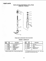
PARTS UST FOR CRAFTSMAN 20" DRILL PRESS
MODEL NO. 113.213213
52
=O
51
5O
49
4
8
\
%,
9
46
43
9
1
42
10
12
41
ro
34
23
25
28
32
18
22
29
31 30 29
27
/
19
21
24
26
FIGURE
1 PARTS
LIST
PARTS UST FOR CRAFTSMAN 20" DRILL PRESS
MODEL NO. 113.213213
Always order by Part Number -- Not by Key Number
fig
FIGURE 1 - PARTS UST
_oy!
I
1
No_
1STD835016
I 2 1817317
G)
03
13
1817688
14
J817336
I
I
I
I
I
I
I
!
I
I
I
I
I
I
I
I STD852012
ISTD84!2!71
I 817719
J STD840812
I STD851008
1822004
I STD835020
5
6
7
8
9
10
11
12
13
14
15
16
17
18
19
Key
No
Part
1817689
J 817320
J 817687
I 821750
1817343
I 817300
1817711
1817710
* Screw-Hex Hd M8 x ! ,25-16
Lever=Adjusting
Support-Motor Bracket
MountoMotor
*Lockwasher
12mm
*Nut-HexM12x1,75
• Motor
*Nut-HexM8x1.25
*WasherM8x16x1.6
Cord-Motor
* Screw-Hex Hd M8 x 1,25-20
Support-MotorBracket
Knob-Motor Adjusting
Handle-BeltTension
Screw-SocSetM10x
1,5-12
Lock-DepthScrew
Guide-Scale
Knob
Rod
Hub
I 21
I 22
I 817774-2
1817303
Ring-DepthStopw/Scate
Pin-Stop
I 23
I 820239-2
I
I
I
I
I
I
I
I
STD852005
820240-3
817697
817698
816!13
Description
Description
I 20 1822084
24
25
26
27
Pa_
No.
Screw-Soc
M8 x 1.25-30
Hd Cap
* Lockwasher-Ext. 5
Screw-Pan Cr M5 x 08-6
Box-Switch
Screw-Pan Cr M6 x 1.0-35
29
820248_2
30
31
32
33
34
35
9_22256
817699
817354
8!7698q
818511
820239
36
817308
37
38
39
4O
41
42
43
44
45
46
47
48
49
5O
5!
52
STD8410!5
817667
813249-152
817685
817686
821738-3
822003-1
813249-53
822216-5
STD375008
820244
817321
813317-6
813317-7
813317-8
813317-9
SP5868
Switch-Locking
Screw Self !ap Pan Hd
M4,2 x 1.4,-8
t Key-Switch
Cover-Switch Piate
Switch *Rocker
Screw.Pan Cr M6 x ! ,0,15
Lead-3"
Screw-Soc Hd Cap
M8 x 125-25
Screw-Special Set
Mt0 x 1.5-27
* Nut-Hex M!0 x t .5
Seat-Spring
Pin-Roll 6 x 16
Spring-Torsion
Cap-Spring
Nut-Hex M12 x 1.5-8
Cord-Power
Pin-Roll 2,5-10
Head w/Pointer & Trim
* Connector-Wire
ScrewoPan Cr M6 x t,0-t2
Socket-Bulb
Wrench-Hex "L'_M3
Wrench-Hex "L" M4
WrenchoHex "L" M5
Wrench-Hex "L" M6
Owners Manual
(Not I!lustrated)
•Any Attempt to Repair This Motor May Create a Hazard Unless Repair is Done by a Quaiified Service Technician,
Repair Service is Available at your nearest Sears Store.
* Standard Hardware
t Stock Item-,-May
Item..-May
Be Purchased
Be Secured Through
Locally,
The Hardware
Department
Of Most Sears Retait Stores,
repair parts
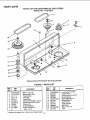
PARTS LiST FOR CRAFTSMAN 20" DRILL PRESS
MODEL NO. 113.213213
19
I
15
2
14
13
l
7
12
FIGURE 2 - PARTS LIST
34
repair pa s
PARTS LIST FOR CRAFTSMAN 20" DRILL PRESS
MODEL NO, 113,213213
Always order by Part Number-Not
by Key Number
FIGURE 2 - PARTS LIST
Key
No.
Part
No.
1
2
817663
817391-1
3
4
5
6
7
822334
817712
817713
817662
817391
8
9
817661
STD837040
Description
Collar-Rack
Screw-Hex Soc Set
M6 x 1.0-10
Support-Table w/Indicator
Crank
Handle-Crank
Rack
Screw-Hex Soc Set
M_0x 1.5-12
Support-Column
* Screw-Hex Hd
M12 x 1.75-40
* Standard Hardware item - May be purchased locally
35
Key
No.
Part
No.
10
11
12
13
14
15
16
17
18
19
817709
819042
817720
STD840812
822069
817789
817288
817294
817350
817349
Description
Base
Tube-Column
Pin-Table Lock
* Nut-Hex M8 x 1.25
Screw-Hex Hd M20 x 2.5-50
Table-Drill Press w/Scale
Pin-Gear
Clamp-Column
Gear-Hefical
Worm-Elevation
repair parts
PARTS LiST FOR CRAFTSMAN 20" DRILL PRESS
MODEL NO. 113.213213
11
12
12
..---3
6
7
Always order by Part Number-Not
FIGURE 3 -PARTS
I
Key i
No.
Part
No.
1
2
3
4
5
6
7
822057
817682
817681
STD315245
817684
817675
817326
Description
Lock-Nut M20 x 1.5
Ring-Locking
Washer
* Bearing-Ball20ram
Washer-Rubber
Tube-Quill
Key-Drift
by Key Number
LIST
:Key
No.
Pad
No.
8
9
10
11
12
13
823253
817340-5
824014
817676
STD315265
817679
Description
tt
Key-Chuck
Chuck (Includes Key No. 8)
Arbor
Spindle
* Bearing-Ball 30mm
Bearing-Thrust
tt - For alternate chuck and key with 1/32" - 5/8" capacity order part no. 817340 (chuck & key)
* Standard Hardware Item -May be purchased locally
36
repair parts
PARTS UST FOR CRAFTSMAN 20" DRILL PRESS
MODEL NO. 113.213213
20
7
\
9
Always order by Part Number-Not
by Key Number
FIGURE 4 - PARTS LIST
Key
1
2
3
4
5.
6
7
8
9
10
Part
No.
STD304290
STD315225
817715
817716
817717
817391-5
816755-3
63418
817451-1
817358-1
Key
No.
Description
Part
No.
L
11
12
13
14
15
16
17
18
19
2O
21
* Belt-"V" 1/2 x 29
* Bearing-Ball 15mm
Pulley-Center
Pivot Idler
Pulley-Motor
Screw-Soc Set M8 x 1o25-12
Screw-Pan Hd M5 x 0.8-12
Clamp-Cord
Bushing-Rubber
Screw-Rd Wash Hd
M6 x 1.0-16
Standard Hardware Item - May be purchased locally
37
Description
iii
STD852006
820294
822059
817668
STD315265
817670
817671
817705
822060
STD304330
817325
* Lockwasher Ext, M6
Washer Foam
Guard-Pulley w/Label
Ring-Retaining
* Bearing-Ball 30mrn
Spacer-Bearing
Insert-Pulley
Pulley-Spindle
Nut-Pulley
* Belt-"_r 1/2 x 33
Knob
Notes
38
39
MOTORIZED
1
MODEL NO.
113.213213
20° NC
USTRIAL ATE DRILL
For the repair or replacement paAs you need
Call 7 am - 7 pro, 7 days a week
1-800°3G6-PART
(1-880-366q278)
DRILLPRESS WITH
MAXUMUM
DEVELOPED
For in-home major brand repair service
Call 24 hours a day, 7 days a week
2 HP MOTOR
1-800-4-REPAIR
(1-880-473-7247)
The model number of your
drill press is found at the rear
of the head.
When requesting service or
ordering parts, always provide the following information:
For the location of a
Sears Repair Service Center in your area
Call 24 hours a day,7 days a week
t -800-488-1222
• Product Type
• Model Number
• Part Number
o Part Description
For information on purchasing a Sears
Maintenance Agreement or to inquire
about an existing Agreement
Call 9 am - 5 pm, Monday-Saturday
1-800-827-6655
SEARS
_.
•:"'_, .
*_
America's
Specialists
Repair
J
J
Sold by SEARS, ROEBUCK AND CO., Hoffman Estates, IL 60195 U.S.A.
Part No. SP5868
Form No, SP5868
Printed in China