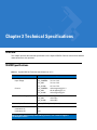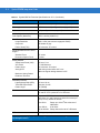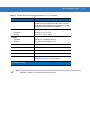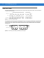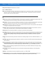
1
Symbol SE6700
Integration Guide
Symbol SE6700
Integration Guide
72E-93549-01
Revision A
July 2007
ii
Symbol SE6700 Integration Guide
© 2007 by Motorola, Inc. All rights reserved.
No part of this publication may be reproduced or used in any form, or by any electrical or mechanical means,
without permission in writing from Motorola. This includes electronic or mechanical means, such as
photocopying, recording, or information storage and retrieval systems. The material in this manual is subject to
change without notice.
The software is provided strictly on an “as is” basis. All software, including firmware, furnished to the user is on
a licensed basis. Motorola grants to the user a non-transferable and non-exclusive license to use each
software or firmware program delivered hereunder (licensed program). Except as noted below, such license
may not be assigned, sublicensed, or otherwise transferred by the user without prior written consent of
Motorola. No right to copy a licensed program in whole or in part is granted, except as permitted under
copyright law. The user shall not modify, merge, or incorporate any form or portion of a licensed program with
other program material, create a derivative work from a licensed program, or use a licensed program in a
network without written permission from Motorola. The user agrees to maintain Motorola’s copyright notice on
the licensed programs delivered hereunder, and to include the same on any authorized copies it makes, in
whole or in part. The user agrees not to decompile, disassemble, decode, or reverse engineer any licensed
program delivered to the user or any portion thereof.
Motorola reserves the right to make changes to any software or product to improve reliability, function, or
design.
Motorola does not assume any product liability arising out of, or in connection with, the application or use of
any product, circuit, or application described herein.
No license is granted, either expressly or by implication, estoppel, or otherwise under any Motorola, Inc.,
intellectual property rights. An implied license only exists for equipment, circuits, and subsystems contained in
Motorola products.
MOTOROLA and the Stylized M Logo and Symbol and the Symbol logo are registered in the US Patent &
Trademark Office. Bluetooth is a registered trademark of Bluetooth SIG. Microsoft, Windows and ActiveSync
are either registered trademarks or trademarks of Microsoft Corporation. All other product or service names
are the property of their respective owners.
Motorola, Inc.
One Motorola Plaza
Holtsville, New York 11742-1300
http://www.symbol.com
Patents
This product is covered by one or more of the patents listed on the website: www.symbol.com/patents
iii
Revision History
Changes to the original manual are listed below:
Change
-01 Rev A
Date
7/2007
Description
Initial Release.
iv
Symbol SE6700 Integration Guide
Table of Contents
About This Guide
Introduction ....................................................................................................................
Chapter Descriptions .....................................................................................................
Notational Conventions..................................................................................................
Referenced Documents .................................................................................................
Service Information........................................................................................................
vii
vii
vii
viii
viii
Chapter 1: Getting Started
Overview .......................................................................................................................
Symbol SE6700 ............................................................................................................
Image Sensor ..........................................................................................................
Aiming System ........................................................................................................
Aiming Error ............................................................................................................
Aiming Control ........................................................................................................
Illumination System .................................................................................................
Illumination Control .................................................................................................
1-1
1-1
1-2
1-3
1-3
1-3
1-3
1-3
Chapter 2: Installation
Overview .......................................................................................................................
General Information ......................................................................................................
Electrostatic Discharge (ESD) ................................................................................
Environment ............................................................................................................
Mounting .......................................................................................................................
Housing Design ............................................................................................................
Optical ...........................................................................................................................
Positioning the Exit Window ....................................................................................
Avoiding Scratched Windows .................................................................................
Window Material .....................................................................................................
Commercially Available Coatings ...........................................................................
A Word About Coatings ..........................................................................................
Optical Path and Exit Window ......................................................................................
2-1
2-1
2-1
2-1
2-2
2-3
2-3
2-3
2-3
2-4
2-4
2-5
2-6
vi
Symbol SE6700 Integration Guide
Chapter 3: Technical Specifications
Overview .......................................................................................................................
SE6700 Specifications ..................................................................................................
Image Sensor Specifications ........................................................................................
Skew, Pitch and Roll ...............................................................................................
Decode Zones ..............................................................................................................
Near Focus .............................................................................................................
Far Focus ................................................................................................................
Decode Distances in Darkness ...............................................................................
3-1
3-1
3-4
3-5
3-6
3-6
3-8
3-10
Chapter 4: Electrical Interface
Overview ....................................................................................................................... 4-1
Symbol SE6700 ............................................................................................................ 4-1
Connector Drawings ..................................................................................................... 4-3
Chapter 5: Application Notes
Overview ....................................................................................................................... 5-1
Output Data Format ...................................................................................................... 5-1
Output Data Timing ....................................................................................................... 5-2
Glossary
Index
Tell Us What You Think...
About This Guide
Introduction
The Symbol SE6700 Integration Guide discusses the theory of operation, installation, and specifications of the
engine, and how to integrate the engine into data capture devices.
NOTE
This guide provides general instructions for the installation of the engine into a customer's device. It is
recommended that an opto-mechanical engineer perform an opto-mechanical analysis prior to
integration.
Chapter Descriptions
The manual includes the following chapters.
• Chapter 1, Getting Started, provides an overview of the engine and the theory of operation.
• Chapter 2, Installation, explains how to install the engine, including information on mounting, housing design,
grounding, ESD, and environmental considerations.
• Chapter 3, Technical Specifications, provides technical specifications for the engine, including decode
ranges.
• Chapter 4, Electrical Interface, includes signal information.
• Chapter 5, Application Notes, provides output data information.
viii
Symbol SE6700 Integration Guide
Notational Conventions
The following conventions are used in this document:
• Bullets indicate:
• action items
• lists of alternatives
• lists of required steps that are not necessarily sequential
• Sequential lists (e.g., those that describe step-by-step procedures) appear as numbered lists.
Referenced Documents
• Symbol PL6707 Decoder Integration Guide, p/n 72E-94096-xx
• The I2C-Bus Specification, Version 2.1,
http://www.semiconductors.philips.com/acrobat/literature/9398/39340011.pdf
• MT9M001 Micron Megapixel CMOS Digital Image Sensor Specification, http://www.micron.com
• Molex connector specification, 52559-3072, http://www.molex.com
Service Information
If you have a problem with your equipment, contact Motorola Enterprise Mobility Support for your region. Contact
information is available at: http://www.symbol.com/customersupport. If you purchased your Enterprise Mobility
business product from a Motorola business partner, contact that business partner for support.
Before contacting, have the model number and serial number at hand. If your problem cannot be solved by
Motorola Enterprise Mobility Support, you may need to return your equipment for servicing and will be given
specific directions.
Motorola is not responsible for any damages incurred during shipment if the approved shipping container is not
used. Shipping the units improperly can possibly void the warranty.
Chapter 1 Getting Started
CAUTION
Per FDA and IEC standards, the engine described in this guide is not given a laser classification.
However, the following precautions should be observed:
This laser component emits CDRH Class II/IEC Class I laser light. Do not stare into beam.
Overview
The Symbol SE6700 provides digital images which can be transmitted to the PL6707 decoder to decode a bar
code of any format supported by the decoding software. The Symbol SE6700 uses laser aiming and LED
illumination.
Symbol SE6700
The Symbol SE6700 contains:
• a monochrome megapixel (1280 x 1024) CMOS imager
• a laser-based aiming system
• an illumination system.
1-2
Symbol SE6700 Integration Guide
Figure 1-1 provides a block diagram of the imager system.
Sensor
Clock
Oscillator
I2 C
Monochrome
Mega PIxel
CMOS
Image Sensor
Pixel Data &
Camera Control
Laser & Drive
Circuitry
(Aiming)
LED Drive
Circuitry
Aim Enable
Illumination
Enable
Figure 1-1 Symbol SE6700 Block Diagram
A 30-pin ZIF connector on the Symbol SE6700 connects the engine and the PL6707 decoder via a 40 mm flex
(available from Symbol, p/n 15-99087-01, via KT-SE6700-02/02R). For information about this connector and flex,
see Figure 4-1 on page 4-3 and Figure 4-3 on page 4-5.
The Visible Laser Diode (VLD) and a diffractive optical element (DOE) in the Symbol SE6700 generate an aiming
pattern. The illumination LED allows image capture in any lighting condition.
Image Sensor
The primary component of the imager system is an SXGA 1/2" format CMOS monochrome megapixel resolution
sensor which contains a 1280 x 1024 pixel array. It supports camera functions such as windowing, column and row
skip mode, and snapshot mode. Its low-noise CMOS imaging technology achieves CCD image quality based on
signal-to-noise ratio and low-light sensitivity.
The sensor is programmable via a two-wire serial interface for frame size, exposure, gain setting, and other
parameters. The default mode outputs an SXGA-size image at 30 frames per second (fps). An on-chip
analog-to-digital converter (ADC) provides 10 bits per pixel (the SE6700 outputs the upper 8 bits only).
FRAME_VALID and LINE_VALID signals are output on dedicated pins, with a pixel clock that is synchronous with
valid data.
Control Register
A ctive-Pixel
Sensor (AP S)
Array
SXGA
1,280H x 1,024V
Timing and Control
Two-wire serial
Input/Output
Clo ck
Sync
Signals
Analog Processin g
AD C
Figure 1-2 Image Sensor Block Diagram
10 -bit Data
Getting Started
1-3
Aiming System
A 650 nm laser and a DOE generate a laser-aiming pattern which represents the imager's field of view throughout
its entire depth of field. The aiming subsystem uses a visible laser diode, a lens, and a diffractive optical element to
generate the aiming pattern. The pattern's center cross hairs indicates the center of the field of view.
Figure 1-3 Aiming Pattern
Aiming Error
The aiming pattern is designed to eliminate divergence (parallax) between the aiming axis and the imaging axis.
See Table 3-1 on page 3-1 for Aiming Element specifications.
Aiming Control
The aiming subsystem is under dynamic software control and is independent of the illumination subsystem.
The Symbol SE6700 can capture images with both the aiming subsystem turned on (the image of the aiming
pattern is captured in the digital image) and the aiming subsystem turned off.
Illumination System
An illumination subsystem, consisting of four red 630 nm LEDs, is provided to meet the image capture and
decoding requirements throughout the full range of ambient lighting (total darkness to full sunlight).
Illumination Control
The Symbol SE6700 can capture images with the illumination subsystem turned on or off, accommodating images
that are close to the wavelength of the illumination. For example, since red LED illumination is used, it may be
desirable to shut off the illumination when capturing a printed image in red ink.
1-4
Symbol SE6700 Integration Guide
Chapter 2 Installation
Overview
This chapter provides information for mounting and installing the Symbol SE6700, including physical and electrical
considerations, and recommended window properties for the SE6700.
General Information
Electrostatic Discharge (ESD)
The Symbol SE6700 is protected from ESD events that may occur in an ESD-controlled environment. Use care
when handling this component and apply standard ESD handling procedures such as using grounding wrist straps
and handling in a properly grounded work area.
Environment
The engine and decoder must be sufficiently enclosed to prevent dust from gathering on the laser lens, optical
lens, illumination system LEDs, and especially the CMOS imager. Dust and other external contaminants eventually
degrade unit performance. Motorola does not guarantee performance of the Symbol SE6700 when used in an
exposed application.
2-2
Symbol SE6700 Integration Guide
Mounting
There are four mounting holes (#0 - 48) and two locator holes on the bottom of the chassis (see Figure 2-1). The
Symbol SE6700 can be mounted in any orientation without degradation in performance.
NOTE
Mounting the Symbol SE6700 in a non-upright position results in images rotated accordingly in snapshot
or video mode.
When installing the mounting screws, ensure they do not protrude past the mounting hole depth (6.0 mm) in the
chassis; use 5.5 mm maximum mounting screw thread engagement. Recommended mounting screw torque is 1.5
±0.2 in-lb.
Notes: Unless otherwise specified:
• Nominal aiming pattern envelope is 30o x 40o.
• Nominal imaging FOV envelope is 35o x 44o.
• Maximum envelopes do not include integration
tolerances.
• Mounting and location information:
see Hole Information.
• General tolerance: ±0.25 mm / ±0.01 in.
• This is a reference drawing and is not intended
to specify or guarantee all possible integration
requirements for this engine.
Hole Information
A. Mounting hole for #0 BT screw: 0.188 in. engagement.
B. Hole for Ø2 mm, 5.5 mm max. long locating pin if desired.
C. Fixture hole for manufacturing.
Hole location tolerance = ±0.15 mm / ±0.006 in.
Figure 2-1 Symbol SE6700 Mounting Diagram
Installation
2-3
Housing Design
NOTE
Opto-mechanical analysis is recommended for housing design to ensure optimal scanning or imaging
performance.
Design the housing so that internal reflections from the illumination system are not directed back toward the
engine. The reflections from the window can cause problems, and for particular window tilt angles, these
reflections can bounce off the top or bottom of the housing and reach the engine.
The Exit Window Information (Figure 2-2 on page 2-6) provides minimum exit window dimensions and tilt angles.
These dimensional requirements can vary. Consider using matte-finished dark internal housing colors.
Optical
The Symbol SE6700 uses a sophisticated optical system that provides imaging performance that matches or
exceeds the performance of much larger imagers. However, the performance of the SE6700 can be affected by an
improperly designed enclosure, or improper selection of window material.
Positioning the Exit Window
Position the window so that illumination system light reflected off the inside of the window is not reflected back into
the engine (see Figure 2-2 on page 2-6). The specified angle is the minimum; allow for manufacturing tolerances. If
the designed enclosure cannot accommodate the recommended window angle, contact Motorola to discuss
positioning requirements. An improperly positioned window can significantly decrease performance.
Avoiding Scratched Windows
Scratches on the window can greatly reduce the performance of the imaging system. We recommend recessing
the window into the housing or applying a scratch resistance coating.
2-4
Symbol SE6700 Integration Guide
Window Material
Many window materials that look clear can contain stresses and distortions that reduce performance. For this
reason, only cell-cast plastics or optical glass is recommended (with or without an anti reflection coating,
depending on the application). Following are descriptions of three popular window materials: PMMA, ADC
(CR-39TM), and chemically tempered float glass. Table 2-1 outlines the suggested window properties.
Table 2-1 Suggested Window Properties
Property
Description
Material
Clear cell-cast acrylic
Thickness
0.06 in. (1.5 mm)
Wavefront Distortion (transmission)
0.2 wavelengths peak-to-valley maximum and
0.04 λ maximum rms over any 0.08 in.
diameter within the clear aperture
Clear Aperture
To extend to within 0.04 in. of the edges all
around
Surface Quality
60-20 scratch/dig
Cell Cast Acrylic (ASTM: PMMA)
Cell Cast Acrylic, or Poly-methyl Methacrylic (PMMA) is fabricated by casting acrylic between two precision sheets
of glass. This material has very good optical quality, reasonably good impact resistance and low initial cost, but is
relatively soft and susceptible to attack by chemicals, mechanical stresses, and UV light. Therefore polysiloxane
coating is strongly recommended. Acrylic can be laser cut into odd shapes and ultrasonically welded.
Cell Cast ADC (ASTM: ADC)
Also known as CR-39TM, Allyl Diglycol Carbonate (ADC) is a thermal-setting plastic produced by cell-casting. Most
plastic eyeglasses sold today are uncoated, cell-cast
CR-39. This material has excellent chemical and environmental resistance, and reasonably good impact
resistance. It also has quite good surface hardness, and therefore does not have to be hard-coated, but may be
coated for severe environments. This material cannot be ultrasonically welded.
Chemically Tempered Float Glass
Glass is a hard material that provides excellent scratch and abrasion resistance. However, unannealed glass is
brittle. Increasing flexibility strength with minimal optical distortion requires chemical tempering. Glass cannot be
ultrasonically welded and is difficult to cut into odd shapes.
Commercially Available Coatings
Anti-Reflection Coatings
Anti-reflection coatings can be used for stray light control or to achieve maximum working range, and can be
applied to the inside and/or outside of the window to reduce the amount of light reflected off the window back into
the engine. However, they are expensive and have very poor abrasion and scratch resistance.
Installation
2-5
Polysiloxane Coating
Polysiloxane type coatings are applied to plastic surfaces to improve the surface resistance to both scratch and
abrasion.
To gauge a window's durability, use ASTM standard D1044, Standard Test Method for Resistance of Transparent
Plastics to Surface Abrasion (the Taber Test), which quantifies abrasion resistance as a percent increase in haze
after a specified number of cycles and load. Lower values of the increase in haze correspond to better abrasion
and scratch resistance. See Table 2-2.
Table 2-2 Taber Test Results on Common Exit Window Materials
Haze 100
cycles
Sample
Haze 500
cycles
Chemically Tempered
Float Glass
1.20%
1.50%
PMMA with
Polysiloxane
Hardcoat
3%
10%
ADC
5%
30%
PMMA
30%
Abrasion
Resistance
Best
Worst
* All measurements use a 100 gram load and CS-10F Abraser.
A Word About Coatings
In all cases, adhere to the minimum tilt angle specified in Figure 2-2 on page 2-6. When the Symbol SE6700 is set
to an exposure time less than 10 milliseconds and gain less than 127, anti-reflection coating is not necessary.
Otherwise, consider single-side or double-side AR coatings. If using an anti-reflective coating, polysiloxane coating
is not required. Recess the exit window to minimize scratches and digs.
If using an anti-reflective coating, the specifications in Table 2-3 apply.
Table 2-3 AR Coatings Specifications
Feature
Description
Material
Both tempered glass and plastic (e.g., CR-39 or hard coated
acrylic) exit windows can be AR coated. AR coated glass is
easier and more durable because of a better adhesion property
on the glass structure. In addition, it can be more cost effective
to put an AR coating on the glass substrate rather than on the
plastic.
AR Coating
Specification
1. One side tempered AR coating: 92% minimum within
spectrum range from 450nm to 700nm.
2. Double side AR coating: One side AR coating must be 97%
minimum within spectrum range from 450nm to 700nm.
2-6
Symbol SE6700 Integration Guide
Optical Path and Exit Window
Notes: Unless otherwise specified:
•
•
•
Recommended exit window information:
•
Exit window to be placed at a maximum distance of 6.0 mm
from lower chassis corner to inner window surface.
•
To avoid illumination light reflecting back into engine, the
minimum exit window tilt angle is 26.0o.
•
Minimum clear aperture: Vertical = 19.2 mm / 0.756 in.
Horizontal = 19.0 mm / 0.748 in
General tolerance: ±0.25 mm / ±0.01 in.
Integration tolerances are not included.
Aiming pattern rotational tolerance
Figure 2-2 Symbol SE6700 Optical Path and Exit Window
Chapter 3 Technical Specifications
Overview
This chapter provides the technical specifications of the Symbol SE6700. Decode zone and exit window
characteristics are also provided.
SE6700 Specifications
Table 3-1 Symbol SE6700 Technical Specifications at 23° C
Item
Power Requirements
Input Voltage
Description
VCC_CAMERA:
VCC_AIM:
VCC_ILLUM:
VCC_CAMERA:
VCC_AIM:
VCC_ILLUM:
3.0 V to 3.6 V
3.0 V to 3.6 V
4.5 V to 5.5 V
100 mA typical @ 3.3 V
40 mA typical @ 3.3 V
162 mA typical @ 5 V
Maximum Power Supply Noise
VCC_CAMERA:
VCC_AIM:
VCC_ILLUM:
15 mVp-p
100 mVp-p
100 mVp-p
Minimum Optical Resolutions
6.67 mil (PDF417), 5 mil (Code 39)
Specular Dead Zone
Illumination On
Illumination Off
15º
None
Current
Note: For best image quality when taking pictures, use a filter to suppress
incoming Vcc noise.
3-2
Symbol SE6700 Integration Guide
Table 3-1 Symbol SE6700 Technical Specifications at 23° C (Continued)
Item
Description
Skew Tolerance
± 60º from normal (see Figure 3-1 on page 3-5)
Pitch Angle
± 65º from normal (see Figure 3-1 on page 3-5)
Roll
360º (see Figure 3-1 on page 3-5)
Ambient Light Immunity for Bar
Code Capture (Maximum)
9000 ft. candles (96,900 lux)
Scan Element
Image Resolution
Gray Level
Field of View (FOV)
1280 x 1024 (monochrome megapixel CMOS)
256 shades of gray
44º horizontal, 35º vertical
Focusing Distance from Front of
Engine
Standard Focus
Document Capture Focus
4.5 inches
8 inches
Aiming Element
Visible Laser Diode (VLD)
VLD Power
Pattern Angle
Aiming Error
Maximum Aiming Pattern
Rotational Tolerance
Illumination Element
Light Emitting Diode (LED)
Total LED Output Power
Pattern Angle
650 nm ± 5 nm
0.7 mW Maximum
40º horizontal, 30º vertical
Total aiming vertical offset is 9.0 mm
Maximum angular aiming tolerance is 2.5º
2.0º
630 nm ± 20 nm
Less than 10 mW
50º (FWHM)
Shock
2000 ± 5% G applied via any mounting surface at -20º,
20º and 55º C for a period of 0.9 ± 10% msec
Vibration
Unpowered SE6700 withstands a random vibration along
each of the X, Y and Z axes for a period of one hour per
axis (6 G rms), defined as follows:
20 to 80 Hz
Ramp up to 0.04 G2/Hz at the rate of
3dB/octave
80 to 350 Hz
0.04 G2/Hz
350 to 2000 Hz Ramp down at the rate of 3 dB/octave
ESD
± 2 Kv (pin injection)
Note: For best image quality when taking pictures, use a filter to suppress
incoming Vcc noise.
Technical Specifications
Table 3-1 Symbol SE6700 Technical Specifications at 23° C (Continued)
Item
Laser Class
Description
The engine, by itself, is an unclassified component. It is
intended for use in CDRH Class II/IEC Class 1 devices
with proper housing, labeling, and instructions to comply
with federal and/or international standards.
Temperature
Operating
Storage
-20º to 55º C (-4º to 131º F)
-40º to 70º C (-40º to 158ºF)
Humidity
Operating
Storage
95% RH, non-condensing at 60º C
85% RH, non-condensing at 70º C
Height
1.02 in. (26.00 mm) maximum
Width
1.77 in. (44.96 mm) maximum
Depth
1.25 in. (31.75 mm) maximum
Weight
0.6 oz. (17.0 grams)
Electrical Interface
30 pin 0.5 mm pitch ZIF connector (refer to Chapter 4,
Electrical Interface for more information.)
Note: For best image quality when taking pictures, use a filter to suppress
incoming Vcc noise.
NOTE
Environmental and/or tolerance parameters are not cumulative. A thermal analysis is recommended if the
application is subject to an extreme temperature environment.
3-3
3-4
Symbol SE6700 Integration Guide
Image Sensor Specifications
Table 3-2 Symbol SE6700 Technical Specifications at 23° C
Item
Description
Optical Format
0.5” (5:4)
Active Imager Size
0.26 in. H x 0.21 in. V (6.66 mm H x 5.32 mm V)
Active Pixels
1,280 H x 1,024 V
Pixel Size
5.2 µm x 5.2 µm
Shutter Type
Electronic Rolling Shutter (ERS)
Data Rate/Master Clock
48 MPS / 48 MHz
Frame Rate
SXGA (1280 x 1024)
30 fps progressive scan; programmable
ADC Resolution
10-bit, on-chip
Responsivity
2.1 V / lux-sec
Dynamic Range
68.2 dB
SNRMAX
45 dB
Technical Specifications
3-5
Skew, Pitch and Roll
Measured on a 20 mil Code 39 symbol at a distance of 10 inches. Tolerance is reduced at extreme ends of the
working range.
Pitch
Skew
+ 65° from normal
+ 60° from normal
Roll
360°
Note: Tolerances are reduced at
extreme ends of the working
range.
Figure 3-1 Skew, Pitch and Roll
3-6
Symbol SE6700 Integration Guide
Decode Zones
Standard Range
The decode zone for the SE6700-SR Standard Range is shown in Figure 3-2. Typical values are shown. Table 3-3
lists the typical and guaranteed distances for selected bar code densities. The minimum element width (or “symbol
density”) is the width in mils of the narrowest element (bar or space) in the symbol.
Note: Typical performance at 73°F (23°C)
on high quality symbols in normal room light.
Vcc = 3.3V
SE6700
5 mil
2.5
6.67 mil PDF417
3.0
3.0
10 mil PDF417
4.7
0
0
9.5
7.8
10.0
15 mil PDF417
9.3
20 mil
2.5
In.
cm
9.0
13 mil (100% UPC)
2.5
3
7.6
6
15.2
2.0
5.1
0
0
2.0
5.1
4.0 10.2
6.8
10 mil I 2 of 5
2.3
cm
10.2
7.0
7.5 mil
2.5
in.
4.0
9
22.9
14.5
12
30.5
Depth of Field
* Minimum distance determined by symbol length and scan angle.
Figure 3-2 SE6700-SR Standard Range Decode Zone
15
38.1
W
i
d
t
h
o
f
F
i
e
l
d
Technical Specifications
Table 3-3
SE6700-SR Standard Range Decode Distances
Symbol
Density/
Bar Code Type
Bar Code
Content/
ContrastNote 2
Typical Working
Ranges
Near
Far
Guaranteed Working
Ranges
Near
Far
5.0 mil
Code 39
ABCDEFGH
80% MRD
2.5 in
6.35 cm
7.0 in
17.78 cm
3.0 in
7.62 cm
6.0 in
15.24 cm
6.67 mil
PDF417
4 Col, 20 Rows
80% MRD
3.0 in
7.62 cm
6.8 in
17.27 cm
3.5 in
8.89 cm
6.0 in
15.24 cm
7.5 mil
Code 39
ABCDEF
80% MRD
2.5 in
6.35 cm
9.0 in
22.86 cm
2.9 in
7.37 cm
7.2 in
18.29 cm
10 mil
I 2 of 5
ITF-14
2:5:1
2.3 in
5.84 cm
9.5 in
24.13 cm
2.7 in
6.86 cm
8.0 in
20.32 cm
10 mil
PDF417
3 Col, 17 Rows
80% MRD
3.0 in
7.62 cm
7.8 in
19.81 cm
3.5 in
8.89 cm
6.5 in
16.51 cm
13 mil
UPC-A
012345678905
80% MRD
2.5 in
6.35 cm
10.0 in
25.40 cm
2.6 inNote 1
6.60 cm
8.3 in
21.08 cm
15 mil
PDF417
80% MRD
4.7 in
11.94 cm
9.3 in
23.62 cm
Note 1
7.8 in
19.81 cm
20 mil
Code 39
123
80% MRD
2.5 in
6.35 cm
14.5 in
36.83 cm
Note 1
12.0 in
30.48 cm
Notes:
1. Near distances are field-of-view (FOV) limited.
2. Contrast is measured as Mean Reflective Difference (MRD) at 670 nm.
3. Working range specifications at temperature = 23°C, pitch=15°, roll=0°,
skew=0°, photographic quality, ambient light ~30 ft-c, humidity 45-70% RH.
3-7
3-8
Symbol SE6700 Integration Guide
Document Capture
The decode zone for the SE6700-DC Document Capture is shown in Figure 3-3. Typical values are shown. Table
3-4 lists the typical and guaranteed distances for selected bar code densities. The minimum element width (or
“symbol density”) is the width in mils of the narrowest element (bar or space) in the symbol.
Note: Typical performance at 73°F (23°C)
on high quality symbols in normal room light.
Vcc = 3.3V
SE6700
5 mil
4.2
10.0
6.67 mil PDF417
4.8
9.8
7.5 mil
2.5
14.3
10 mil I 2 of 5
3.3
10 mil PDF417
12.7
4.0
13 mil (100% UPC)
2.5
4.7
0
0
16.3
15 mil PDF417
15.3
20 mil
2.8
In.
cm
15.3
5
12.7
10
25.4
15
38.1
23.0
20
50.8
25
63.5
Depth of Field
* Minimum distance determined by symbol length and scan angle.
Figure 3-3 SE6700-DC Document Capture Decode Zone
in.
cm
8
20.3
4
10.2
0
0
4
10.2
8
20.3
W
i
d
t
h
o
f
F
i
e
l
d
Technical Specifications
Table 3-4
SE6700-DC Document Capture Decode Distances
Typical Working
Ranges
Guaranteed Working
Ranges
Symbol
Density/
Bar Code Type
Bar Code
Content/
ContrastNote 2
5.0 mil
Code 39
ABCDEFGH
80% MRD
4.2 in
10.67 cm
10.0 in
25.40 cm
5.0 in
12.70 cm
8.5 in
21.59 cm
6.67 mil
PDF417
4 Col, 20 Rows
80% MRD
4.8 in
12.19 cm
9.8 in
24.89 cm
6.0 in
15.24 cm
8.5 in
21.59 cm
7.5 mil
Code 39
ABCDEF
80% MRD
2.5 in
6.35 cm
14.3 in
36.32 cm
3.3 in
8.38 cm
12.3 in
31.24 cm
10 mil
I 2 of 5
ITF-14
2:5:1
3.3 in
8.38 cm
15.3 in
38.86 cm
3.9 in
9.91 cm
13.0 in
33.02 cm
10 mil
PDF417
3 Col, 17 Rows
80% MRD
4.0 in
10.16 cm
12.7 in
32.26 cm
5.0 in
12.70 cm
10.0 in
25.40 cm
13 mil
UPC-A
012345678905
80% MRD
2.5 in
6.35 cm
16.3 in
41.40 cm
2.6 inNote 1
6.60 cm
13.6 in
34.54 cm
15 mil
PDF417
80% MRD
4.7 in
11.94 cm
15.3 in
38.86 cm
Note 1
12.2 in
30.99 cm
20 mil
Code 39
123
80% MRD
2.8 in
7.11 cm
23.0 in
58.42 cm
Note 1
18.5 in
46.99 cm
Near
Far
Near
Far
Notes:
1. Near distances are FOV limited.
2. Contrast is measured as Mean Reflective Difference (MRD) at 670 nm.
3. Working range specifications at temperature = 23°C, pitch=15°, roll=0°,
skew=0°, photographic quality, ambient light ~30 ft-c, humidity 45-70% RH.
3-9
3 - 10 Symbol SE6700 Integration Guide
Decode Distances in Darkness
Table 3-5
Decode Distances in Darkness
Symbol
Density/
Bar Code Type
Bar Code
Content/
ContrastNote 2
5.0 mil
Code 39
ABCDEFGH
80% MRD
6.67 mil
PDF417
7.5 mil
Code 39
10 mil
I 2 of 5
10 mil
PDF417
13 mil
UPC-A
4 Col, 20 Rows
80% MRD
ABCDEF
80% MRD
ITF-14
2:5:1
3 Col, 17 Rows
80% MRD
012345678905
80% MRD
Typical Working Ranges
Focus Position
Near
Far
Standard Range
2.5 in
6.35 cm
7.0 in
17.78 cm
Document Capture
4.2 in
10.67 cm
9.8 in
24.89 cm
Standard Range
3.0 in
7.62 cm
6.8 in
17.27 cm
Document Capture
4.8 in
12.19 cm
9.8 in
24.89 cm
Standard Range
2.5 in
6.35 cm
8.8 in
22.35 cm
Document Capture
2.5 in
6.35 cm
14.0 in
35.56 cm
Standard Range
2.3 in
5.84 cm
9.4 in
23.88 cm
Document Capture
3.3 in
8.38 cm
15.0 in
38.10 cm
Standard Range
3.0 in
7.62 cm
7.8 in
19.81 cm
Document Capture
4.0 in
10.16 cm
12.5 in
31.75 cm
Standard Range
2.5 in
6.35 cm
9.8 in
24.89 cm
Document Capture
2.5 in
6.35 cm
16.0 in
40.64 cm
Notes:
1. Near distances are FOV limited.
2. Contrast is measured as Mean Reflective Difference (MRD) at 670 nm.
3. Working range specifications at temperature = 23°C, pitch=15°, roll=0°,
skew=0°, photographic quality, humidity 45-70%RH.
4. Range measurements are when VCC_ILLUM is powered off of 3.0 V (see Table
4-1 on page 4-1). Powering VCC_ILLUM off of 3.3 V yields slightly improved
working ranges in darkness.
Technical Specifications 3 - 11
Table 3-5
Decode Distances in Darkness (Continued)
Symbol
Density/
Bar Code Type
Bar Code
Content/
ContrastNote 2
15 mil
PDF417
80% MRD
20 mil
Code 39
123
80% MRD
Typical Working Ranges
Focus Position
Near
Far
Standard Range
4.7 in
11.94 cm
9.0 in
22.86 cm
Document Capture
4.7 in
11.94 cm
14.0 in
35.56 cm
Standard Range
2.5 in
6.35 cm
13.0 in
33.02 cm
Document Capture
2.8 in
7.11 cm
19.0 in
48.26 cm
Notes:
1. Near distances are FOV limited.
2. Contrast is measured as Mean Reflective Difference (MRD) at 670 nm.
3. Working range specifications at temperature = 23°C, pitch=15°, roll=0°,
skew=0°, photographic quality, humidity 45-70%RH.
4. Range measurements are when VCC_ILLUM is powered off of 3.0 V (see Table
4-1 on page 4-1). Powering VCC_ILLUM off of 3.3 V yields slightly improved
working ranges in darkness.
3 - 12 Symbol SE6700 Integration Guide
Chapter 4 Electrical Interface
Overview
The Symbol SE6700 has one 30-pin connector. See Figure 2-1 on page 2-2 for the pin one location, on the side
opposite the aiming/illumination system.
Symbol SE6700
Table 4-1 lists the pins and signals of the 30-pin connector on the Symbol SE6700.
Table 4-1 Symbol SE6700 Signal Information
Pin
Number
SE6700 Signal
Name
I/O
Notes
30
GND
Pwr
Ground
29
PCLK
O
Pixel Clock
28
GND
Pwr
Ground
27
LINE_VALID
O
Valid Line Pixel Data
26
VCC_ILLUM
Pwr
Illumination Power
25
VCC_AIM
Pwr
Aiming Power
24
RESET*
I
Reset Pin
23
VCC_CAMERA
Pwr
Camera Power
22
TRIGGER
I
Activates Snapshot Sequence
21
ILLUM_EN*
I
LED Illumination Control
(when LEFT_DSBL and RIGHT_DSBL are each low)
A low turns the illumination LEDs on.
A high turns the illumination LEDs off.
4-2
Symbol SE6700 Integration Guide
Table 4-1 Symbol SE6700 Signal Information (Continued)
Pin
Number
SE6700 Signal
Name
I/O
Notes
20
AIM_EN*
I
Laser Aiming Control
A low turns the AIM laser on.
A high turns the AIM laser off.
19
PIX_DATA0
O
Pixel Data Bit 0 (LSB)
18
PIX_DATA1
O
Pixel Data Bit 1
17
PIX_DATA2
O
Pixel Data Bit 2
16
PIX_DATA3
O
Pixel Data Bit 3
15
PIX_DATA4
O
Pixel Data Bit 4
14
PIX_DATA5
O
Pixel Data Bit 5
13
PIX_DATA6
O
Pixel Data Bit 6
12
PIX_DATA7
O
Pixel Data Bit 7
11
LEFT_DSBL
I
Left Illumination Control
A high disables the left illumination LED bank
when ILLUM_EN* is low.
A low enables the left illumination LED bank
when ILLUM_EN* is low.
10
FRAME_VALID
O
Valid Frame Pixel Data
9
OSC_EN
I
Oscillator Enable
8
STROBE
7
I2C_SDA
I/O
I2C-BUS Data Line
6
I2C_SCL
I
I2C-BUS Clock Line
5
OE
I
Output Enable
4
N/C
-
No Connect
3
STANDBY
I
Standby Mode
2
RIGHT_DSBL
I
Right Illumination Control
A high disables the right illumination LED bank
when ILLUM_EN* is low.
A low enables the right illumination LED bank
when ILLUM_EN* is low.
1
SCAN_STAND*
O
Scan Stand Mode
End of Sensor Reset
Electrical Interface
Connector Drawings
Notes:
1.
Material:
Housing: 46NYLON UL94V-0
Actuator: PPS UL94V-0
Terminal: phosphor bronze, tin-bismuth 1.0 micrometer minimum,
nickel under plating, 1.0 micrometer minimum
Fitting nail: phosphor bronze, tin 1.0 micrometer minimum,
nickel under plating, 1.0 micrometer minimum
2.
Dimensions are in mm.
3.
Misalignment of solder tails and fitting nails from
Upper direction: 0.05 max.,
Lower direction: 0.15 max.
4.
Apply for even circuit.
G
Figure 4-1 SE6700 Engine Interface Connector (30 position, 0.5 mm, ZIF),
p/n 50-12167-030 (Molex p/n 52559-3072)
4-3
4-4
Symbol SE6700 Integration Guide
Dimensions are in mm unless otherwise specified.
Figure 4-2 SE6700 Engine Interface Connector (30 position, 0.5 mm, ZIF),
p/n 50-12167-030 (Molex p/n 52559-3072) (continued)
Electrical Interface
Note: Dimensions are in inches.
Figure 4-3 SE6700 to PL6707-B300R Flex, p/n 15-99087-01 (Included in KT-SE6700-02R)
4-5
4-6
Symbol SE6700 Integration Guide
Chapter 5 Application Notes
Overview
This chapter includes output data information.
Output Data Format
The sensor image data is read out in a progressive scan. Horizontal blanking and vertical blanking surrounds valid
image data as shown in Figure 5-1. LINE_VALID is HIGH during the shaded region. See Output Data Timing for
FRAME_VALID timing information.
P0,0 P 0,1 P 0,2 .....................................P
P1,0 P 1,1 P 1,2 .....................................P
0,n-1
1,n-1
P0,n
P1,n
HORIZONTAL
BLANKING
VALID IMAGE
Pm-1,0 P m-1,1 .....................................P
Pm,0 P m,1 .....................................P
Pm-1,n
Pm,n
m-1,n-1
m,n-1
00 00 00 ..................................... 00 00 00
00 00 00 ..................................... 00 00 00
VERTICAL BLANKING
00 00 00 ..................................... 00 00 00
00 00 00 ..................................... 00 00 00
Figure 5-1 Image Readout
00 00 00 .................. 00 00 00
00 00 00 .................. 00 00 00
00 00 00 .................. 00 00 00
00 00 00 .................. 00 00 00
00 00 00 .................. 00 00 00
00 00 00 .................. 00 00 00
VERTICAL/HORIZONTAL
BLANKING
00 00 00 .................. 00 00 00
00 00 00 .................. 00 00 00
5-2
Symbol SE6700 Integration Guide
Output Data Timing
The sensor’s data output is synchronized with the PCLK output. When LINE_VALID is HIGH, one 8-bit pixel datum
is output every PCLK period.
....
LINE_VALID
....
PCLK
Blanking
PIX_DATA(7:0)
P0
P1
P2
Blanking
....
Valid Image Data
P3
P4
....
Pn-1
Pn
Figure 5-2 Pixel Data Timing Example
The rising edges of the PCLK signal are nominally timed to occur on the rising PIX_DATA edges. This allows PCLK
to be used as a clock to latch the data. PIX_DATA data is valid on the falling edge of PCLK. The PCLK is HIGH
when the master clock is HIGH, and LOW when the master clock is LOW. It is always enabled, even during the
blanking period.
...
FRAME_VALID
...
LINE_VALID
...
Figure 5-3 Row Timing and FRAME_VALID/LINE_VALID Signals
Glossary
A
Aperture. The opening in an optical system defined by a lens or baffle that establishes the field of view.
API. An interface by means of which one software component communicates with or controls another. Usually used to refer
to services provided by one software component to another, usually via software interrupts or function calls
Application Programming Interface. See API.
ASCII. American Standard Code for Information Interchange. A 7 bit-plus-parity code representing 128 letters, numerals,
punctuation marks and control characters. It is a standard data transmission code in the U.S.
Autodiscrimination. The ability of an interface controller to determine the code type of a scanned bar code. After this
determination is made, the information content is decoded.
B
Bar. The dark element in a printed bar code symbol.
Bar Code. A pattern of variable-width bars and spaces which represents numeric or alphanumeric data in machine-readable
form. The general format of a bar code symbol consists of a leading margin, start character, data or message character,
check character (if any), stop character, and trailing margin. Within this framework, each recognizable symbology uses
its own unique format. See Symbology.
Bar Code Density. The number of characters represented per unit of measurement (e.g., characters per inch).
Bar Height. The dimension of a bar measured perpendicular to the bar width.
Bar Width. Thickness of a bar measured from the edge closest to the symbol start character to the trailing edge of the same
bar.
Bit. Binary digit. One bit is the basic unit of binary information. Generally, eight consecutive bits compose one byte of data.
The pattern of 0 and 1 values within the byte determines its meaning.
Glossary - 2
Symbol SE6700 Integration Guide
Bits per Second (bps). Bits transmitted or received.
bps. See Bits Per Second.
Byte. On an addressable boundary, eight adjacent binary digits (0 and 1) combined in a pattern to represent a specific
character or numeric value. Bits are numbered from the right, 0 through 7, with bit 0 the low-order bit. One byte in
memory is used to store one ASCII character.
C
CDRH. Center for Devices and Radiological Health. A federal agency responsible for regulating laser product safety. This
agency specifies various laser operation classes based on power output during operation.
CDRH Class 1. This is the lowest power CDRH laser classification. This class is considered intrinsically safe, even if all laser
output were directed into the eye's pupil. There are no special operating procedures for this class.
CDRH Class 2. No additional software mechanisms are needed to conform to this limit. Laser operation in this class poses
no danger for unintentional direct human exposure.
Character. A pattern of bars and spaces which either directly represents data or indicates a control function, such as a
number, letter, punctuation mark, or communications control contained in a message.
Character Set. Those characters available for encoding in a particular bar code symbology.
Check Digit. A digit used to verify a correct symbol decode. The scanner inserts the decoded data into an arithmetic formula
and checks that the resulting number matches the encoded check digit. Check digits are required for UPC but are
optional for other symbologies. Using check digits decreases the chance of substitution errors when a symbol is
decoded.
Codabar. A discrete self-checking code with a character set consisting of digits 0 to 9 and six additional characters: ( - $ : /
, +).
Code 128. A high density symbology which allows the controller to encode all 128 ASCII characters without adding extra
symbol elements.
Code 3 of 9 (Code 39). A versatile and widely used alphanumeric bar code symbology with a set of 43 character types,
including all uppercase letters, numerals from 0 to 9 and 7 special characters (- . / + % $ and space). The code name is
derived from the fact that 3 of 9 elements representing a character are wide, while the remaining 6 are narrow.
Code 93. An industrial symbology compatible with Code 39 but offering a full character ASCII set and a higher coding
density than Code 39.
Code Length. Number of data characters in a bar code between the start and stop characters, not including those
characters.
COM Port. Communication port; ports are identified by number, e.g., COM1, COM2.
Continuous Code. A bar code or symbol in which all spaces within the symbol are parts of characters. There are no
intercharacter gaps in a continuous code. The absence of gaps allows for greater information density.
Glossary - 3
D
Dead Zone. An area within a scanner's field of view, in which specular reflection may prevent a successful decode.
Decode. To recognize a bar code symbology (e.g., UPC/EAN) and then analyze the content of the specific bar code
scanned.
Decode Algorithm. A decoding scheme that converts pulse widths into data representation of the letters or numbers
encoded within a bar code symbol.
Depth of Field. The range between minimum and maximum distances at which a scanner can read a symbol with a certain
minimum element width.
Discrete 2 of 5. A binary bar code symbology representing each character by a group of five bars, two of which are wide.
The location of wide bars in the group determines which character is encoded; spaces are insignificant. Only numeric
characters (0 to 9) and START/STOP characters may be encoded.
Discrete Code. A bar code or symbol in which the spaces between characters (intercharacter gaps) are not part of the code.
E
EAN. European Article Number. This European/International version of the UPC provides its own coding format and
symbology standards. Element dimensions are specified metrically. EAN is used primarily in retail.
Element. Generic term for a bar or space.
Encoded Area. Total linear dimension occupied by all characters of a code pattern, including start/stop characters and data.
ENQ (RS-232). ENQ software handshaking is also supported for the data sent to the host.
ESD. Electro-Static Discharge
H
Host Computer. A computer that serves other terminals in a network, providing such services as computation, database
access, supervisory programs and network control.
Hz. Hertz; A unit of frequency equal to one cycle per second.
I
IEC. International Electrotechnical Commission. This international agency regulates laser safety by specifying various laser
operation classes based on power output during operation.
Glossary - 4
Symbol SE6700 Integration Guide
IEC (825) Class 1. This is the lowest power IEC laser classification. Conformity is ensured through a software restriction of
120 seconds of laser operation within any 1000 second window and an automatic laser shutdown if the scanner's
oscillating mirror fails.
Input/Output Ports. I/O ports are primarily dedicated to passing information into or out of the terminal’s memory. Series
9000 mobile computers include Serial and USB ports.
Intercharacter Gap. The space between two adjacent bar code characters in a discrete code.
Interleaved 2 of 5. A binary bar code symbology representing character pairs in groups of five bars and five interleaved
spaces. Interleaving provides for greater information density. The location of wide elements (bar/spaces) within each
group determines which characters are encoded. This continuous code type uses no intercharacter spaces. Only
numeric (0 to 9) and START/STOP characters may be encoded.
Interleaved Bar Code. A bar code in which characters are paired together, using bars to represent the first character and
the intervening spaces to represent the second.
Internet Protocol Address. See IP.
IOCTL. Input/Output Control.
I/O Ports. interface The connection between two devices, defined by common physical characteristics, signal
characteristics, and signal meanings. Types of interfaces include RS-232 and PCMCIA.
L
LASER. Light Amplification by Stimulated Emission of Radiation.The laser is an intense light source. Light from a laser is
all the same frequency, unlike the output of an incandescent bulb. Laser light is typically coherent and has a high energy
density.
Laser Diode. A gallium-arsenide semiconductor type of laser connected to a power source to generate a laser beam. This
laser type is a compact source of coherent light.
Laser Scanner. A type of bar code reader that uses a beam of laser light.
LCD. See Liquid Crystal Display.
LED Indicator. A semiconductor diode (LED - Light Emitting Diode) used as an indicator, often in digital displays. The
semiconductor uses applied voltage to produce light of a certain frequency determined by the semiconductor's particular
chemical composition.
Light Emitting Diode. See LED.
Liquid Crystal Display (LCD). A display that uses liquid crystal sealed between two glass plates. The crystals are excited
by precise electrical charges, causing them to reflect light outside according to their bias. They use little electricity and
react relatively quickly. They require external light to reflect their information to the user.
Glossary - 5
M
MIL. 1 mil = 1 thousandth of an inch.
Misread (Misdecode). A condition which occurs when the data output of a reader or interface controller does not agree with
the data encoded within a bar code symbol.
Mobile Computer. In this text, mobile computer refers to the Symbol Series 9000 wireless portable computer. It can be set
up to run as a stand-alone device, or it can be set up to communicate with a network, using wireless radio technology.
N
Nominal. The exact (or ideal) intended value for a specified parameter. Tolerances are specified as positive and negative
deviations from this value.
Nominal Size. Standard size for a bar code symbol. Most UPC/EAN codes are used over a range of magnifications (e.g.,
from 0.80 to 2.00 of nominal).
NVM. Non-Volatile Memory.
P
Parameter. A variable that can have different values assigned to it.
PC Card. A plug-in expansion card for laptop computers and other devices, also called a PCMCIA card. PC Cards are
85.6mm long x 54 mm wide, and have a 68 pin connector. There are several different kinds:
•
Type I; 3.3 mm high; use - RAM or Flash RAM
•
Type II; 5 mm high; use - modems, LAN adaptors
•
Type III; 10.5 high; use - Hard Disks
PCMCIA. Personal Computer Memory Card Interface Association. See PC Card.
Percent Decode. The average probability that a single scan of a bar code would result in a successful decode. In a
well-designed bar code scanning system, that probability should approach near 100%.
Print Contrast Signal (PCS). Measurement of the contrast (brightness difference) between the bars and spaces of a
symbol. A minimum PCS value is needed for a bar code symbol to be scannable. PCS = (RL - RD) / RL, where RL is
the reflectance factor of the background and RD the reflectance factor of the dark bars.
Programming Mode. The state in which a scanner is configured for parameter values. See Scanning Mode.
Glossary - 6
Symbol SE6700 Integration Guide
Q
Quiet Zone. A clear space, containing no dark marks, which precedes the start character of a bar code symbol and follows
the stop character.
QWERTY. A standard keyboard commonly used on North American and some European PC keyboards. “QWERTY” refers
to the arrangement of keys on the left side of the third row of keys.
R
RAM. Random Access Memory. Data in RAM can be accessed in random order, and quickly written and read.
Reflectance. Amount of light returned from an illuminated surface.
Resolution. The narrowest element dimension which is distinguished by a particular reading device or printed with a
particular device or method.
RS-232. An Electronic Industries Association (EIA) standard that defines the connector, connector pins, and signals used to
transfer data serially from one device to another.
S
Scan Area. Area intended to contain a symbol.
Scanner. An electronic device used to scan bar code symbols and produce a digitized pattern that corresponds to the bars
and spaces of the symbol. Its three main components are: 1) Light source (laser or photoelectric cell) - illuminates a bar
code,; 2) Photodetector - registers the difference in reflected light (more light reflected from spaces); 3) Signal
conditioning circuit - transforms optical detector output into a digitized bar pattern.
Scanning Mode. The scanner is energized, programmed and ready to read a bar code.
Scanning Sequence. A method of programming or configuring parameters for a bar code reading system by scanning bar
code menus.
SDK. Software Development Kit
Self-Checking Code. A symbology that uses a checking algorithm to detect encoding errors within the characters of a bar
code symbol.
SMDK. Symbol Mobility Developer’s Kit.
Space. The lighter element of a bar code formed by the background between bars.
Specular Reflection. The mirror-like direct reflection of light from a surface, which can cause difficulty decoding a bar code.
Start/Stop Character. A pattern of bars and spaces that provides the scanner with start and stop reading instructions and
scanning direction. The start and stop characters are normally to the left and right margins of a horizontal code.
Glossary - 7
Substrate. A foundation material on which a substance or image is placed.
Symbol. A scannable unit that encodes data within the conventions of a certain symbology, usually including start/stop
characters, quiet zones, data characters and check characters.
Symbol Aspect Ratio. The ratio of symbol height to symbol width.
Symbol Height. The distance between the outside edges of the quiet zones of the first row and the last row.
Symbol Length. Length of symbol measured from the beginning of the quiet zone (margin) adjacent to the start character
to the end of the quiet zone (margin) adjacent to a stop character.
Symbology. The structural rules and conventions for representing data within a particular bar code type (e.g. UPC/EAN,
Code 39, PDF417, etc.).
T
Terminal Emulation. A “terminal emulation” emulates a character-based mainframe session on a remote non-mainframe
terminal, including all display features, commands and function keys. The VC5000 Series supports Terminal Emulations
in 3270, 5250 and VT220.
Tolerance. Allowable deviation from the nominal bar or space width.
U
UPC. Universal Product Code. A relatively complex numeric symbology. Each character consists of two bars and two
spaces, each of which is any of four widths. The standard symbology for retail food packages in the United States.
V
Visible Laser Diode (VLD). A solid state device which produces visible laser light.
Glossary - 8
Symbol SE6700 Integration Guide
Index
A
aiming . . . . . . . . . . . . . . . . . . . . . . . . . . . . . . . . . . . . 1-3
control . . . . . . . . . . . . . . . . . . . . . . . . . . . . . . . . . 1-3
delays . . . . . . . . . . . . . . . . . . . . . . . . . . . . . . . . . 3-1
element . . . . . . . . . . . . . . . . . . . . . . . . . . . . . . . . 3-2
ambient light immunity . . . . . . . . . . . . . . . . . . . . . . . . 3-2
anti-reflection coatings . . . . . . . . . . . . . . . . . . . . .2-4, 2-5
application notes . . . . . . . . . . . . . . . . . . . . . . . . . . . . 5-1
E
B
blanking . . . . . . . . . . . . . . . . . . . . . . . . . . . . . . . . . . . 5-1
block diagram . . . . . . . . . . . . . . . . . . . . . . . . . . . . . . 1-2
bullets . . . . . . . . . . . . . . . . . . . . . . . . . . . . . . . . . . . . . vii
C
chapter descriptions . . . . . . . . . . . . . . . . . . . . . . . . . . vii
CMOS . . . . . . . . . . . . . . . . . . . . . . . . . . . . . . . . . . . . 1-1
coatings . . . . . . . . . . . . . . . . . . . . . . . . . . . . . . . .2-4, 2-5
connector
drawings . . . . . . . . . . . . . . . . . . . . . . . . . . . . . . . 4-3
considerations
optical . . . . . . . . . . . . . . . . . . . . . . . . . . . . . . . . . 2-3
avoiding scratched windows . . . . . . . . . . . . . 2-3
positioning exit window . . . . . . . . . . . . . . . . . 2-3
conventions
notational . . . . . . . . . . . . . . . . . . . . . . . . . . . . . . . vii
D
data format
output . . . . . . . . . . . . . . . . . . . . . . . . . . . . . . . . .
data timing . . . . . . . . . . . . . . . . . . . . . . . . . . . . . . . . .
pixel data . . . . . . . . . . . . . . . . . . . . . . . . . . . . . . .
row . . . . . . . . . . . . . . . . . . . . . . . . . . . . . . . .
decode distances
far focus . . . . . . . . . . . . . . . . . . . . . . . . . . . . . . . 3-9
in darkness . . . . . . . . . . . . . . . . . . . . . . . . . . . . 3-10
near focus . . . . . . . . . . . . . . . . . . . . . . . . . . . . . . 3-7
decode zones . . . . . . . . . . . . . . . . . . . . . . . . . . . . . . 3-6
far focus . . . . . . . . . . . . . . . . . . . . . . . . . . . . . . . 3-8
near focus . . . . . . . . . . . . . . . . . . . . . . . . . . . . . . 3-6
dimensions . . . . . . . . . . . . . . . . . . . . . . . . . . . . . . . . 3-3
5-1
5-2
5-2
5-2
electrical interface . . . . . . . . . . . . . . . . . . . . . . . . . . . 3-3
signal information . . . . . . . . . . . . . . . . . . . . . . . . 4-1
ESD . . . . . . . . . . . . . . . . . . . . . . . . . . . . . . . . . . . 2-1, 3-3
exit window
avoiding scratches . . . . . . . . . . . . . . . . . . . . . . . 2-3
coatings . . . . . . . . . . . . . . . . . . . . . . . . . . . . . . . 2-4
diagram . . . . . . . . . . . . . . . . . . . . . . . . . . . . . . . . 2-6
material . . . . . . . . . . . . . . . . . . . . . . . . . . . . . . . . 2-4
positioning . . . . . . . . . . . . . . . . . . . . . . . . . . . . . 2-3
properties . . . . . . . . . . . . . . . . . . . . . . . . . . . . . . 2-4
F
flex connector . . . . . . . . . . . . . . . . . . . . . . . . . . . . . .
focus positions
distance from engine . . . . . . . . . . . . . . . . . . . . .
far focus decode distances . . . . . . . . . . . . . . . . .
far focus decode zone . . . . . . . . . . . . . . . . . . . .
near focus decode distances . . . . . . . . . . . . . . .
near focus decode zone . . . . . . . . . . . . . . . . . . .
1-2
3-2
3-9
3-8
3-7
3-6
H
housing design . . . . . . . . . . . . . . . . . . . . . . . . . . . . . 2-3
humidity specification . . . . . . . . . . . . . . . . . . . . . . . . 3-3
Index - 2
Symbol SE6700 Integration Guide
I
illumination system . . . . . . . . . . . . . . . . . . . . . . . . . .
image readout . . . . . . . . . . . . . . . . . . . . . . . . . . . . . .
installation
environment . . . . . . . . . . . . . . . . . . . . . . . . . . . .
housing . . . . . . . . . . . . . . . . . . . . . . . . . . . . . . . .
mounting . . . . . . . . . . . . . . . . . . . . . . . . . . . . . . .
optical considerations . . . . . . . . . . . . . . . . . . . . .
positioning exit window . . . . . . . . . . . . . . . . . . . .
1-3
5-1
2-1
2-3
2-2
2-3
2-3
L
laser . . . . . . . . . . . . . . . . . . . . . . . . . . . . . . . . . . . . . . 1-3
LED . . . . . . . . . . . . . . . . . . . . . . . . . . . . . . . . . . .1-3, 3-2
M
Motorola enterprise mobility support . . . . . . . . . . . . . . viii
mounting . . . . . . . . . . . . . . . . . . . . . . . . . . . . . . . . . . 2-2
diagram . . . . . . . . . . . . . . . . . . . . . . . . . . . . . . . . 2-2
skew, pitch and roll . . . . . . . . . . . . . . . . . . . . . . 3-2, 3-5
specular dead zone . . . . . . . . . . . . . . . . . . . . . . . . . . 3-2
support . . . . . . . . . . . . . . . . . . . . . . . . . . . . . . . . . . . . .viii
T
technical specifications
SE6700 . . . . . . . . . . . . . . . . . . . . . . . . . . . . . . . . 3-1
sensor . . . . . . . . . . . . . . . . . . . . . . . . . . . . . . . . . 3-4
temperature specification . . . . . . . . . . . . . . . . . . . . . . 3-3
timing . . . . . . . . . . . . . . . . . . . . . . . . . . . . . . . . . . . . . 5-2
pixel data . . . . . . . . . . . . . . . . . . . . . . . . . . . . . . . 5-2
row . . . . . . . . . . . . . . . . . . . . . . . . . . . . . . . . . . . . 5-2
V
vibration specification . . . . . . . . . . . . . . . . . . . . . . . . . 3-3
visible laser diode . . . . . . . . . . . . . . . . . . . . . . . 1-2, 3-2
W
weight . . . . . . . . . . . . . . . . . . . . . . . . . . . . . . . . . . . . 3-3
N
notational conventions . . . . . . . . . . . . . . . . . . . . . . . . . vii
Z
ZIF connector . . . . . . . . . . . . . . . . . . . . . . . . . . . . . . . 1-2
O
optical . . . . . . . . . . . . . . . . . . . . . . . . . . . . . . . . . . . .
avoiding scratched windows . . . . . . . . . . . . . . . .
exit window material . . . . . . . . . . . . . . . . . . . . . .
path and exit window diagram . . . . . . . . . . . . . .
positioning exit window . . . . . . . . . . . . . . . . . . . .
resolution . . . . . . . . . . . . . . . . . . . . . . . . . . . . . .
output data
timing . . . . . . . . . . . . . . . . . . . . . . . . . . . . . . . . .
output data format . . . . . . . . . . . . . . . . . . . . . . . . . . .
overview . . . . . . . . . . . . . . . . . . . . . . . . . . . . . . . . . .
2-3
2-3
2-4
2-6
2-3
3-1
5-2
5-1
1-1
P
pinouts . . . . . . . . . . . . . . . . . . . . . . . . . . . . . . . . . . . . 4-1
pitch . . . . . . . . . . . . . . . . . . . . . . . . . . . . . . . . . . . . . . 3-5
R
roll . . . . . . . . . . . . . . . . . . . . . . . . . . . . . . . . . . . . . . . 3-5
S
service information . . . . . . . . . . . . . . . . . . . . . . . . . . . viii
shock specification . . . . . . . . . . . . . . . . . . . . . . . . . . 3-2
signal information . . . . . . . . . . . . . . . . . . . . . . . . . . . 4-1
skew . . . . . . . . . . . . . . . . . . . . . . . . . . . . . . . . . . . . . 3-5
Tell Us What You Think...
We’d like to know what you think about this Manual. Please take a moment to fill out this questionnaire and fax this form
to: (631) 738-4618, or mail to:
Motorola, Inc.
One Motorola Plaza M/S B-10
Holtsville, NY 11742-1300
Attention: Technical Publications Manager
Advanced Data Capture Division
IMPORTANT: If you need product support, please call the appropriate customer support number provided. Unfortunately,
we cannot provide customer support at the fax number above.
Manual Title:___________________________________________
(please include revision level)
How familiar were you with this product before using this manual?
Very familiar
Slightly familiar
Not at all familiar
Did this manual meet your needs? If not, please explain.
______________________________________________________________________________________
______________________________________________________________________________________
______________________________________________________________________________________
______________________________________________________________________________________
What topics need to be added to the index, if applicable?
______________________________________________________________________________________
______________________________________________________________________________________
______________________________________________________________________________________
______________________________________________________________________________________
What topics do you feel need to be better discussed? Please be specific.
______________________________________________________________________________________
______________________________________________________________________________________
______________________________________________________________________________________
______________________________________________________________________________________
What can we do to further improve our manuals?
______________________________________________________________________________________
______________________________________________________________________________________
______________________________________________________________________________________
______________________________________________________________________________________
Thank you for your input—We value your comments.
Motorola, Inc.
One Motorola Plaza
Holtsville, New York 11742, USA
1-800-927-9626
http://www.symbol.com
MOTOROLA and the Stylized M Logo and Symbol and the Symbol logo are registered in the U.S. Patent and Trademark Office.
All other product or service names are the property of their registered owners.
© Motorola, Inc. 2007
72E-93549-01 Revision A - July 2007