1
Chain Vise Recipro Saw
MODEL JR3010
INSTRUCTION MANUAL
SPECIFICATIONS
Length of stroke
28 m m 11-118")
Strokes per minute
0
-
2,200
Vise capacity
:,?,--':-:;
Overall length
Net weight
,without
435 m m 117-1/8")
Manufacturer reserves the right t o change specifications without notice.
* Note: Specifications may differ from country t o country.
2.9 k g (6.4 Ibs)
IMPORTANT
SAFETY INSTRUCTIONS
(For All Tools)
WARNING: WHEN USING ELECTRIC TOOLS, BASIC SAFETY PRECAUTIONS SHOULD ALWAYS BE FOLLOWED TO
REDUCE THE RISK OF FIRE, ELECTRIC SHOCK, AND PERSONAL INJURY, INCLUDING THE FOLLOWING:
READ ALL INSTRUCTIONS.
1. KEEP WORK AREA CLEAN. Cluttered areas and benches invite injuries.
2. CONSIDER WORK AREA ENVIRONMENT. Don't use power tools in damp
or wet locations. Keep work area well lit. Don't expose power tools t o rain.
Don't use tool in presence of flammable liquids or gases.
3. KEEP CHILDREN AWAY. All visitors should be kept away from work area.
Don't let visitors contact tool or extension cord.
4. STORE IDLE TOOLS. When not in use, tools should be stored in dry, and high
or locked-up place - out of reach of children.
5 . DON'T FORCE TOOL. It will do the job better and safer at the rate for which
it was intended.
6. USE RIGHT TOOL. Don't force small tool or attachment t o do the job of a
heavy-duty tool. Don't use tool for purpose not intended.
7 . DRESS PROPERLY. Don't wear loose clothing or jewelry. They can be caught
in moving parts. Rubber gloves and non-skid footwear are recommended
when working outdoors. Wear protective hair covering to contain long hair.
8.USE SAFETY GLASSES. Also use face or dust mask if cutting operation is
dusty.
9. DON'T ABUSE CORD. Never carry tool by cord or yank it t o disconnect from
receptacle. Keep cord from heat, oil, and sharp edges.
IO. SECURE WORK. Use clamps or a vise to hold work. It's safer than using
your hand and it frees both hands to operate tool.
1 1 . DON'T OVERREACH. Keep proper footing and balance at all times.
12. MAINTAIN TOOLS WITH CARE. Keep tools sharp and clean for better and
safer performance. Follow instructions for lubricating and changing accessories. Inspect tool cords periodically and if damaged, have repaired by authorized service facility. Inspect extension cords periodically and replace if
damaged. Keep handles dry, clean, and free from oil and grease.
13.DISCONNECT TOOLS. When not in use, before servicing, and when changing accessories, such as blades, bits, cutters.
2
14. REMOVE ADJUSTING KEYS AND WRENCHES. Form habit of checking t o
see that keys and adjusting wrenches are removed from tool before turning
it on.
15. AVOID UNINTENTIONAL STARTING. Don't carry plugged-in tool with finger
on switch. Be sure switch is OFF when plugging in.
16. OUTDOOR USE EXTENSION CORDS. When tool is used outdoors, use only
extension cords intended for use outdoors and so marked.
17. STAY ALERT. Watch what you are doing, use common sense. Don't operate
tool when you are tired.
18. CHECK DAMAGED PARTS. Before further use of the tool, a guard or other
part that is damaged should be carefully checked t o determine that it will
operate properly and perform its intended function. Check for alignment of
moving parts, binding of moving parts, breakage of parts, mounting, and any
other conditions that may affect its operation. A guard or other part that
is damaged should be properly repaired or replaced by an authorized service center unless otherwise indicated elsewhere in this instruction manual.
Have defective switches replaced by authorized service center. Don't use
tool if switch does not turn it on and off.
19. GUARD AGAINST ELECTRIC SHOCK. Prevent body contact with grounded
surfaces. For example; pipes, radiators, ranges, refrigerator enclosures.
20. REPLACEMENT PARTS. When servicing, use only identical replacement parts.
VOLTAGE WARNING: Before connecting the tool t o a power source (receptacle,
outlet, etc.) be sure the voltage supplied is the same as that specified on the
nameplate of the tool. A power source with voltage greater than that specified
for the tool can result in SERIOUS INJURY t o the user - as well as damage to
the tool. If in doubt, DO NOT PLUG IN THE TOOL. Using a power source with
voltage less than the nameplate rating is harmful to the motor.
3
ADDITIONAL SAFETY RULES
1. Wear a hard hat (safety helmet), safety glasses and/or face shield.
It is also highly recommended that you wear a dust mask, ear protectors
and thickly padded gloves.
2. Check the blade carefully for cracks or damage before operation.
Replace cracked or damaged blade immediately.
3. Do not attempt to cut workpieces
larger than specified in this manual
(especially hollow pipe). The blade
might snap and cause an injury.
4.
5.
6.
7.
Hold the tool firmly.
Be sure no one is below when using the tool in high locations.
Do not point the tool at anyone in the immediate vicinity.
When making a "blind" cut (you can't see behind what is being cut), be
sure that hidden electrical wiring or water pipes are not in the path of the
cut. If wires are present, they must be disconnected at their power source
by a qualified person or avoided to prevent the possibility of lethal shock
or fire. Always hold the tool ONLY by the insulated gripping surfaces to
prevent any electric shock if you accidentally cut through a "live" wire. Water
pipes in "blind" areas must be drained and capped before cutting.
8. Be careful not to hit the end of the
blade against something during
operation. Damage to the tool or
dangerous blade breakage may
occur.
9. Watch out for cut-off portions of the workpiece being cut. They may fall and
injure you or someone near you.
IO. When cutting metals, be cautious of hot flying chips.
11. Do not touch the blade or the workpiece immediately after operation; they
may be extremely hot and could burn your skin.
12. If you withdraw the blade from the workpiece during operation, strong
reaction will be produced, causing the blade to snap or causing you to lose
your grip and control of the tool. Always switch off the tool and wait until
the blade has come to a complete stop before withdrawing the blade from
the workpiece.
SAVE THESE INSTRUCTIONS.
4
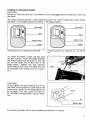
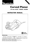
Installing or removing saw blade
CAUTION :
Always be sure that the tool is switched off and unplugged before installing or removing
the blade.
The blade installing position varies depending upon the type of blade being used. Install
the blade in the proper position as shown in the figures below.
Installing position for blades No. 25 and 26.
Installing position for blades No. 21, 22, 23 and
24.
To install the blade, loosen the bolt with
the hex wrench. Insert the blade between
the blade clamp and the slider so that the
pin on the slider f i t s in the hole in the
blade shank. Tighten the bolt securely
while making sure that the blade will not
be extracted even though you try t o pull it
out.
CAUTION :
If you tighten the bolt without the pin on
the slider fitting properly in the hole in the
blade shank, the pin or the blade shank will
be damaged. This may cause the blade t o
be extracted unexpectedly during operation.
Blade clamp
~
To remove the blade, follow the installation procedures in reverse.
5
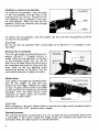
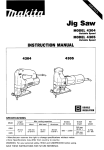
Installing or removing vise assembly
To install the vise assembly, insert the shaft
of the vise assembly into the hole in the
housing as far as it will go. The shaft of the
vise assembly will be grasped by the stopper automatically. Make sure that the vise
assembly cannot be removed even though
you try t o pull it out.
To remove the vise assembly, raise the stopper and then pull the vise assembly out while
turning the vise assembly.
CAUTION :
Do not use the vise assembly when cutting pipes up to 25 mm (1") in diameter or thin
wall pipes.
Securing tool t o workpiece
Turn the vise handle counterclockwise until
approx. 25 mm (1") threaded portion is
visible. Place the vise assembly on the part
of the workpiece which will not fall off
after the cut is made. Wrap the chain around
the workpiece and hook the chain onto the
chain hook on the vise assembly while
maintaining tension on the chain. Turn the
vise handle clockwise t o tighten the chain.
Switch action
Tool speed is increased by increasing pressure on the trigger. To start the tool,
simply pull the trigger. Release the trigger
t o stop. A speed control screw is provided
so that maximum tool speed can be limited
(variable). Turn the speed control screw
clockwise for higher speed, and counterclockwise for lower speed.
CAUTION :
Before plugging in the tool, always check t o see that the trigger switch actuates properly
and returns t o the "OFF" position when released.
Overload protector
The overload protector automatically cuts out t o break the circuit whenever heavy work
is prolonged. If this occurs, release the trigger switch and withdraw the blade from the
workpiece. Press the restart button to resume operation.
6
Operation
1. Cutting with the vise assembly :
Secure the tool to the workpiece as described in “Securing tool to workpiece”
section. Bring the blade into light contact with the workpiece. First, make a
pilot groove, using a slower speed until
the blade has cut t o a depth of 1 - 3 mm
(3/64”- 1/8’)). Then use a faster speed
to continue cutting.
CAUTION :
Do not l i f t the tool handle too hard during operation. This may cause a bevel cut,
damage to the blade or damage to the tool.
When cutting the workpiece which is
not secured with anything other than
the vise assembly, grasp the vise handle
with your left hand and the tool handle
with your right hand. Then cut the
workpiece by raising the tool handle
while pulling the vise handle toward
you. Be extremely careful in these situations to avoid losing control of the tool
and workpiece.
CAUTION :
When cutting the workpiece near an obstacle like floor or wall, use wood blocks to
prevent the blade from hitting against the obstacle.
2 Cutting without the vise assembly :
Press the shoe firmlv against the work-
7
MAINTENANCE
CAUTION :
Always be sure that the tool i s switched off and unplugged before attempting t o perform
inspection or maintenance.
To maintain product SAFETY and RELIABILITY, repairs, carbon brush inspection and
replacement, any other maintenance or adjustment should be performed by Makita
Authorized or Factory Service Centers, always using Makita replacement parts.
ACCESSORIES
CAUTION :
These accessories or attachments are recommended for use with your Makita tool specified in this
manual. The use of any other accessories or attachments might present a risk of injury to persons.
The accessories or attachments should be used only in the proper and intended manner.
assembly
Part No. 122403-9
0
Hex wrench 4
Part No. 783202-0
Vise handle 120
(length: 100 mm; S15/16“)
Part No. 272024-8
0
Steel carrying case
Part No. 182200-5
0 Vise
0
Use this vise handle instead of the
standard equipped vise handle
(length: 180 mm; 7-1/16”) when
cutting in tight places.
Saw Blades
Wood Cutting Blade
Part ##
1723018-0A
723018-A-5
7230 18-A-2
Oty.
Per Pkg.
Teeth
Per Inch
1 I 1
1
I
1
723018-0E
723018-E-5
723018-P-5
I
Metal Cutting Blade
For rapid cutting of
metal and fiberglass.
Made of high speed
steel.
10
1 1 /! 1
6
I
1723018-OD
723018-D5
723018-D-2
I
6'
6'
6"
High Carbon Steel
Fleam Ground
1.049" I
Cuts nail free wood
-rough In work.
12"
High Carbon Steel
Fleam Ground
1.049")
Cuts nail free wood
- rough in work.
6"
6'
6'
6"
6"
!
I
10
5
5
I
1
E
1
I
6
I
I
5
2
I
I
1
72301945
I
723019-OC
723019-C-5
723019-C-2
18
18
I
5
I
Cuts composition
and plywood - resists
nail damange.
18
I
18
Cuts circles and contours in nail free
wood, compositions.
6'
High Alloy Steel
M / V Alternate
(.041")
Cuts plaster, metal
lath, plasterboard.
4,
4"
High Speed Steel
M 11 led/faker Set
1.031")
For cutting metal
over 118" thick.
High Speed Steel
MilledlRaker Set
1.031")
For cutting metal
over 118" thick.
High Speed Steel
Milled/Raker Set
1.031")
For cutting metal
over 3/64" thick.
High Speed Steel
Milled/Wavy Set
1.049")
For scroll cuts in
metal 3/64" thick
and over.
High Speed Steel
Milled/Raker Set
(.031 " )
For cutting metal
over 3 / 6 4 ' thick.
High Speed Steel
Milled/Wavy Set
1.031")
For cutting metal
less than 3/64" thick.
~
4"
4'
I 1 i: I
10
High Alloy Steel
Milled (.031"1
High Carbon Steel
Fleam Ground
l.049")
723019-A-2
7230 19 0 B
723019-8-5
723019-6-2
Cuts composition
materials - resists
nail damage.
6'
6"
I
14
14
Application
High Alloy Steel
Milled 1.031")
I
1s
I
723019-G-5
1723019-G-2
Tooth
Specification
1s
723018-6-5
723018-6-1
723018-OC
7230 18-CS
Overall
Length
4"
6"
E''
723019-D5
723019-0-2
24
6'
6'
High Speed Steel
Milled/Wavy Set
(.031")
For cutting metal
less than 3/64" thick
7230 19-J 5
36
4'
High Speed Steel
Milled/Wavy Set
LO31 "1
For cutting metal
less than 1/32" thick
9
Saw Blades
Bi-metal Blade
Combination of high
speed steel teeth welded
to a shatter proof flexiblf
backed blade. Ultra long
l i f e blade.
Part
I
my.
I
Teeth
Per Pkg. Per Inch
Overall
Length
5
6
12"
1 1
10
10
10
E"
6*
1
I
1
5
4"
I
6"
723017-E5
723017-E-2
723017-F-5
723017.0A
723017-A5
723017-A-2
I I
10
6"
6'
723017-G5
I
I
14
723017-06
723017-85
723017-8-2
I I
14
14
14
I
18
18
723017-H5
723017-H-2
723017-OC
723017-C5
723017-C-2
I
10
1
5
2
4'
4'
I
6"
18
4"
4"
72301 7-J-5
24
6'
E::
72301 7-D-2
792618-8
No. 25
5-718''
1792620- 1
No. 26
1
I
1
7-7/8"
I
I
Application
Cuts nail embedded
M i ~ ~ i ~ e i ~ o , , wood
,
-roughing in
work.
Mi{$Tei:o,,)
Mi&Tei:l,,,
Bi-metal
Milled (.031")
I
Bi-metal
Milled (.031")
Cuts nail embedded
wood - roughing in
work.
Cuts nail embedded
wood - nonferrous
metals.
Cuts metal 1/8" thick
and over.
Cuts metal 1/8" thick
and over.
I
8i-metal
Milled (.031")
E::
3-112''
* A l l illustrations shown
are general representations for blades in that
category. Actual design
of blades may vary
slightly.
I
Bi- metal
Milled 1.031")
I ? I 1;
10
Tooth
Specification
Cuts metal 3 / 6 4 '
thick and over.
Cuts metal 3 / 6 4 '
thick and over.
Scroll cuts in metals
over 3 / 6 4 ' thick, fiberglass, compositions.
mil&^$^\ ,,)
Bi-metal
Milled (.031")
Cuts metal less than
3/64" thick.
Bi-metal
Milled (.031")
Cuts metal less than
3/64'thick.
-
High Speed Steel
I1
I
For iron pipe 2-3/8"
dia. or less.
For iron pipe 4-1 /2"
dia. or less.
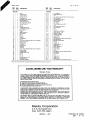
(Note)
1. Use blades N o . 25 or 26 for accurate square c u t t i n g .
2. Blades No. 25 a n d 26 are r e c o m m e n d e d t o use f o r c u t t i n g steel pipes 5/64" t h i c k o r m o r e .
e 3 Piece variety pack
includes 1 each: 723018-A
723018-D
723019-C
Part N o . 723016-3-A
10
e 3 Piece variety Pack
U l t r a long life b i m e t a l
Includes 1 each: 723017-E
723017-8
7230 17- C
Part N o , 723016-3-8
Aug.-17-'89
US
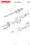
CHAIN VISE RECIPRO SAW
Model JR3010
Note: The switch, noise suppressor and other part configurations
may differ from country t o country.
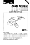
11
MODEL JR3010
,&
M
:i'
Aug - 1 7 ' 8 9
1
2
2
1
15
1
16
17
1
11
18
19
20
21
22
23
24
25
26
27
28
29
30
31
32
33
34
35
38
37
38
39
40
41
42
43
44
45
46
47
48
1
1
1
12
13
14
IO
~
1
2
2
2
2
2
1
US
DESCRIPTION
MACHINE
MACHINE
~
1
2
3
4
5
6
7
8
9
A&,
M
:i'
DESCRIPTION
1
1
1
3
3
3
1
I
I
49
50
51
52
53
54
55
56
1
1
57
58
59
82
83
64
65
66
67
68
69
70
71
72
73
76
77
78
19
80
81
82
83
1
1
1
1
1
1
I
1
1
1
1
1
1
2
1
1
1
1
1
1
1
1
- -
-
1
1
4
4
1
1
1
1
1
I
I
2
1
1
1
1
1
1
1
2
2
1
2
1
1
1
1
1
1
4
-
Thin Washer 6
Nsadla Bearing 510
P," 5
Her Socket Head Bolf M5x16 lWilh Washer1
Spring Washer 4
Pan Head Screw M4x10
Rsiammg Ring 5-10
Gear Housmg
Gam Holder
Thrust Nssdla Bearing 3041
GBW
Pan Head Screw M5x30
Spring Washer 5
Pin 6
Fan 75
ARMATURE ASSEMBLY
IWiIh Item 55 - 581
InsuIafion Washer
Ball Bearing BOBLB
Current Relay
Rubber Pin 4
Pan Haad Screw M5x55 IWifh Waiharl
Bearmg Ratamer
8811 Bearing 8OOlDDW
Rmg 12
0
1
1 Seal 18
R s f m m g Rmg S - 12
BIlIllS P1.f.
FIELD ASSEMBLY
Brush Holdar
Carbon Brush
Switch
Pan Head Screw M4x18 IWith Washer1
Stram Relief
Cord Guard
Cord
Rubber Pm 4
Rubber Pm 4
Handle Cavsr
Pan Head Screw M4r28 lWith Washer1
MAKKA LIMrrED ONE YEAR WARRANTY
Warranty Policy
Every Makita tool is thorau ly inapectcd and tested before leaving the factory. It is warranted to
be free of defects from work6ah1p and materials for the period of ONE YEAR from the date of
oripinnl ourchase. Should MY trouble devclov durinn this one-year period. m u m the COMPLETE
tod. freight prepaid, to one ifMkita's Fact& or Aithorized Semie Centers. If inspection shows
the trouble is c a u d by defective workmanship or materid. Makita will repair (or at our option,
replace) without charge.
This Warranty docs not apply where:
rcp.ita have bccn made or attempted by others:
repain are required because of normd wear and tear:
The toal hrr bscn abuscd. misused or imvroverl~maintained:
alterations have been made to the tool.
IN NO EVEKT SHALL MAKlTA BC LIABLF FOR ANY INDIRkCT. INCIDFNTAL OR CONSLQUENTIAL DAMAGES FROM THE SALE OR U S t O F T H E PRODUCT THIS DISCLAIMER
APPLIES BOTd DURING A N D AFTER THE TERM O F THIS WARRANTY
MAKITA DISCLAIMS LIABILITY FOR ANY IMPLIED WARRANTltS, INCLUDING IMPLItD
WARRANTIES O F "MLRCHANTABILITY" A N D 'FITNESS FOR A SPECIFIC PURPOSE,'
A F T t R THE O N E Y E A R TERM O F T H I S WARRANTY
This Wananty gives you specific legal rights, and you may also have other tights which vary from
state to state. Some s t a t e do not allow the exclusion or limitation of incidental or consequential
damages, so the above limitation or exclusion may not apply to you. Some slates do not allow
limitation on how long sn implied warranty lasts, so the above limitation may not apply to you.
Makita Corporation
3-11-8, Sumiyoshi-cho,
Anjo, Aichi 446 Japan
883700 - 067
PRINTED IN JAPAN
1991 - 6 - N