1
OC272A--1.qxp
03.9.4 11:06 AM
Page 1
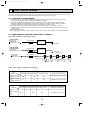
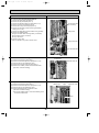
SPLIT-TYPE, HEAT PMUP AIR CONDITIONERS
2003
No.OC272
REVISED EDITION-A
TECHNICAL & SERVICE MANUAL
R407C
Outdoor unit
[Model name]
[Service Ref.]
PUMY-P125VMA
PUMY-P125YMA
PUMY-P125YMA1
PUMY-P125VMA
PUMY-P125YMA
Revision :
• PUMY-P125VMA and
PUMY-P125YMA1 are
added in REVISED
EDITION-A.
• Please void OC272.
CONTENTS
1. TECHNICAL CHANGE ·····································2
2. SAFETY PRECAUTION····································3
3. OVERVIEW OF UNITS······································5
4. SPECIFICATIONS ·············································8
5. DATA ·······························································10
6. OUTLINES AND DIMENSIONS ······················18
7. WIRING DIAGRAM ·········································19
8. NECESSARY CONDITIONS FOR SYSTEM CONSTRUCTION ···22
9. TROUBLESHOOTING ····································34
10. ELECTRICAL WIRING····································72
11. REFRIGERANT PIPING TASKS ·····················75
12. DISASSEMBLY ···············································80
13. PARTS LIST ····················································86
OUTDOOR UNIT
OC272A--1.qxp
1
03.9.4 11:06 AM
Page 2
TECHNICAL CHANGE
PUMY-P125YMA ➔ PUMY-P125YMA1
1. Addition of new function (Auto Change Over)
PUMY-P125YMA : Not equipped
PUMY-P125YMA1 : Equipped
2. Difference of operation switching logic for the outdoor output connector (CN3D)
PUMY-P125YMA : CN3D 1-2 ······ OPEN : Heating CLOSE : Cooling
PUMY-P125YMA1 : CN3D 1-2 ······ OPEN : Cooling CLOSE : Heating
3. Difference of the role of SW5-1 (function selection switch)
PUMY-P125YMA : Fix the operation frequency ······························ ON : Fix
OFF : Normal
PUMY-P125YMA1 : Auto Change Over from Remote Controller ······ ON : Enable OFF : Disable
2
OC272A--1.qxp
2
03.9.4 11:06 AM
Page 3
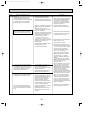
SAFETY PRECAUTION
Cautions for using with the outdoor unit which adopts R407C refrigerant.
· Do not use the existing refrigerant piping.
-The old refrigerant and refrigerant oil in the existing piping contains a large amount of chlorine which may cause the refrigerant oil of the new unit to deteriorate.
· Do not use copper pipes which are broken, deformed or discolour .
In addition, be sure that the inner surfaces of the pipes are clean, free of hazardous sulphur and oxides, or have no dust /
dirt, shaving particles, oils, moisture or any other contamination.
-If there is a large amount of residual oil (hydraulic oil, etc.) inside the piping and joints, deterioration of the refrigerant oil will
result.
· Store the piping to be used during installation indoors and keep both ends of the piping sealed until just before
brazing. (Store elbows and other joints in a plastic bag.)
-If dust, dirt, or water enters the refrigerant cycle, deterioration of the oil and compressor trouble may result.
· Use ester oil, ether oil or alkyl benzene (small amount) as the refrigerant oil to coat flares and flange connections.
-The refrigerant oil will degrade if it is mixed with a large amount of mineral oil.
Use liquid refrigerant to fill the system.
-If gas refrigerant is used to fill the system, the composition of the refrigerant in the cylinder will change and performance
may drop.
· Do not use a refrigerant other than R407C.
-If another refrigerant (R22, etc.) is used, the chlorine in the refrigerant may cause the refrigerant oil to deteriorate.
· Use a vacuum pump with a service port.
-The vacuum pump oil may flow back into the refrigerant cycle and cause the refrigerant oil to deteriorate.
· Do not use the following tools that are used with conventional refrigerant.
(Gauge manifold , charge hose, gas leak detector, reverse flow check valve, refrigerant charge base, vacuum gauge,
refrigerant recovery equipment)
-If the conventional refrigerant and refrigerant oil are mixed in the R407C, the refrigerant may deteriorated.
-If water is mixed in the R407C, the refrigerant oil may deteriorate.
-Since R407C does not contain any chlorine, gas leak detectors for conventional refrigerant will not react to it.
· Do not use a charging cylinder.
-Using a charging cylinder may cause the refrigerant to deteriorate.
· Be especially careful when managing the tools.
-if dust, dirt, or water gets in the refrigerant cycle, the refrigerant may deteriorate.
· Do not use the drier which is sold in the field.
-The drier for R407C refrigerant is pre-attached to outdoor unit refrigerant circuit.
-Some drier in the field are not in conformity with R407C refrigerant.
3
OC272A--1.qxp
03.9.4 11:06 AM
Page 4
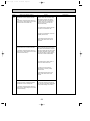
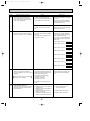
[1] Service tools
Use the below service tools as exclusive tools for R407C refrigerant.
No.
1
Tool name
Specifications
Gauge manifold
·Only for R407C.
·Use the existing fitting SPECIFICATIONS. (UNF 7/16)
·Use high-tension side pressure of 3.43MPa·G or over.
2
Charge hose
·Only for R407C.
·Use pressure performance of 5.10MPa·G or over.
3
Electronic scale
4
5
Gas leak detector
Adapter for reverse flow check.
6
7
·Use the detector for R407C.
·Attach on vacuum pump.
Refrigerant charge base.
Refrigerant cylinder.
·For R407C
·Top of cylinder (Brown)
·Cylinder with syphon
8
Refrigerant recovery equipment.
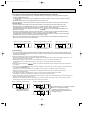
[2] Notice on repair service
·After recovering the all refrigerant in the unit, proceed to working.
·Do not release refrigerant in the air.
·After completing the repair service, recharge the cycle with the specified amount of
liquid refrigerant.
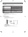
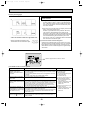
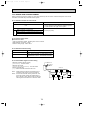
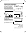
[3] Refrigerant recharging
(1) Refrigerant recharging process
1
Direct charging from the cylinder.
·R407C cylinder are available on the market has a syphon pipe.
·Leave the syphon pipe cylinder standing and recharge it.
(By liquid refrigerant)
Unit
Gravimeter
(2) Recharge in refrigerant leakage case
·After recovering the all refrigerant in the unit, proceed to working.
·Do not release the refrigerant in the air.
·After completing the repair service, recharge the cycle with the specified amount of
liquid refrigerant.
4
OC272A--1.qxp
03.9.4 11:06 AM
3
Page 5
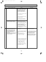
OVERVIEW OF UNITS
3-1. UNIT CONSTRUCTION
5HP
PUMY-P125VMA
PUMY-P125YMA
PUMY-P125YMA1
Outdoor unit
Capacity
Indoor unit
Number of units
that can be
connected Total system wide capacity
Branching pipe
components
Model
CMY-Y62-C-E
CMY-Y64-C
CMY-Y68
CMY-S65
Branch header
(4 branches)
Branch header
(8 branches)
Multi distribution
Piping on outdoor
unit
(5 branches)
2-way flow
1-way flow
PLFY-P
PLFY-P
PMFY-P
–
20VLMD-A
20VBM-A
25
–
25VLMD-A
32
32VKM-A
32VLMD-A
40
40VKM-A
50
Capacity
1~8 units
50~130% of outdoor unit capacity
Branch header
(2 branches)
Cassette Ceiling
4-way flow
Type 20~Type 125
Ceiling
Concealed
Wall Mounted
PDFY-P
PKFY-P
20VML-A / VMM-A
20VM-A
20VAM-A
25VBM-A
25VML-A / VMM-A
25VM-A
32VBM-A
32VML-A / VMM-A
32VM-A
40VLMD-A
40VBM-A
40VMH-A / VMM-A
40VM-A
50VKM-A
50VLMD-A
–
50VMH-A / VMM-A
63
63VKM-A
63VLMD-A
–
71
–
–
80
80VAM-A
80VLMD-A
20
PEFY-P
Ceiling mounted
built-in
Ceiling
Suspended
PCFY-P
Floor standing
Exposed
Concealed
PFFY-P
PFFY-P
–
20VLEM-A
20VLRM-A
25VAM-A
–
25VLEM-A
25VLRM-A
32VGM-A
–
32VLEM-A
32VLRM-A
40VGM-A
40VGM-A
40VLEM-A
40VLRM-A
50VM-A
50VGM-A
–
50VLEM-A
50VLRM-A
63VMH-A / VMM-A
63VM-A
63VFM-A
63VGM-A
63VLEM-A
63VLRM-A
–
71VMH-A / VMM-A
71VM-A
–
–
–
–
–
80VMH-A / VMM-A
80VM-A
–
–
–
–
100
100VAM-A 100VLMD-A
–
100VMH-A / VMM-A
100VM-A
100VFM-A
100VGM-A
–
–
125
125VAM-A 125VLMD-A
–
125VMH-A / VMM-A
125VM-A
–
125VGM-A
–
–
Decorative panel
Name
M-NET remote controller
MA remote controller
PAR-20MAA-E
PAR-F27MEA-E
Remote Model number
controller
• A handy remote controller for use in conjunction • Addresses setting is not necessary.
Functions
with the Melans centralized management system. • Only the indoor unit for MA remote controller
• Addresses must be set.
(the end of model name is -A) can be used.
5
OC272A--1.qxp
03.9.4 11:06 AM
Page 6
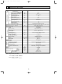
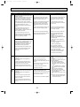
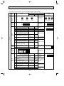
3-2. UNIT SPECIFICATIONS
(1) Outdoor Unit
PUMY-P125VMA
PUMY-P125YMA
PUMY-P125YMA1
Service Ref.
Capacity
Cooling (kW)
14.0
Heating (kW)
16.0
Motor for compressor (kW)
w
3.5
Cooling / Heating capacity indicates the maximum value at operation under the following condition.
w. Cooling Indoor : D.B. 27°C / W.B. 19.0°C
Outdoor : D.B. 35°C
Heating Indoor : D.B. 20°C
Outdoor : D.B. 7°C / W.B. 6°C
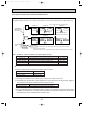
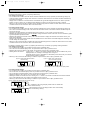
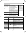
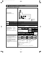
(2) Method for identifying MULTI-S model
■ Outdoor unit <When using model 125 >
■ Indoor unit < When using Model 80 >
P L F Y - P 80 V AM - A
PAC type
L : Ceiling cassette
K : Wall-mounted type
E : Hidden skylight type
C : Ceiling suspended type
M: Ceiling cassette type
F : Floor standing type
Refrigerant
R407C/R22
commonness
MA control
Indicates equivalent
to Cooling capacity
Outdoor unit
AM
KM
M
KM
LMD
}
M-NET
control
Indicates equivalent
to Cooling capacity
Power supply
V: Single phase
220-230-240V 50Hz
220V
60Hz
Cooling
Heating
Indoor-side intake air temperature
W.B. 15~24°C
D.B. 15~27°C
Outdoor-side intake air temperature
D.B. -5~46°C
W.B. -15~15.5°C
D.B. : Dry Bulb Temperature
W.B. : Wet Bulb Temperature
6
Sub-number
M-NET control
Frequency
conversion
controller
(3) Operating temperature range
Notes
Refrigerant
R407C
MULTI-S
Frequency
conversion
controller
NEW frequency converter
one-to-many air conditioners
(flexible design type)
PU M Y - P 125 V M A
Power supply
V: Single phase
220-230-240V 50Hz
Y: 3-phase
380-400-415V 50Hz
380V
60Hz
OC272A--1.qxp
03.9.4 11:06 AM
Page 7
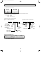
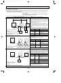
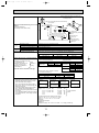
3-3. SYSTEM LAYOUT
3-3-1. System layout
One outdoor unit using branching connectors can be connected to a maximum of eight indoor units.
■Examples of a branching method
Outdoor unit
A
B
First branch
(branching connector)
C
a
indoor
1
D
e
b
c
d
indoor
2
indoor
3
indoor
4
indoor
5
3-3-2. Notes on the connection of indoor and outdoor units
Note: When the total capacity of indoor units exceeds the capacity of the outdoor unit (more than 100%), the rated power of
each indoor unit will be less when they are running simultaneously.
Outdoor unit
PUMY-P125VMA
PUMY-P125YMA
PUMY-P125YMA1
Indoor unit
Indoor unit that can connected
1~8 units
Available capacity of indoor unit
Type 20 ~ Type 125
Total capacity of units that can be included system
(50-130% of outdoor unit capacity)
63~163
3-3-3. Capacity for outdoor unit
(1) Branching pipe
Model
CMY-Y62C-E
Branching connector
NUMBER OF BRANCHING POINTS
2
CMY-Y64-C
4
CMY-Y68
8
CMY-S65
5
(2) Examples of System Construction
PIping method
(All models)
Total capacity of
indoor units.
160
125
Outdoor unit
Indoor units
80
40
40
7
OC272A--1.qxp
03.9.4 11:06 AM
4
Page 8
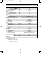
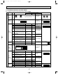
SPECIFICATIONS
Service Ref.
Cooling
Heating
Standard performance
Item
Rated Cooling capacity
Rated power consumption
Operating current
Operating power factor
Starting current
Rated Heating capacity
Rated power consumption
Operating current
Operating power factor
Starting current
Rated power supply
External finish (Munsell colour-coded markings)
Dimensions H o W o D (Note 1)
Heat exchanger type
Compressor
Model
Type o quantity
Starting method
Motor output
Capacity control
Daily cooling capacity
Heater <crankcase>
Refrigerating oil (Model)
Fan Type o quantity
Airflow
Motor output
Defrost method
Pressure gauge
PUMY-P125VMA
kW
kW
A
%
A
kW
kW
A
%
A
14.0
6.10
28.3-27.1-26.0
98
17
16.0
6.03
28.0-26.7-25.7
98
17
Single phase 220-230-240V 50Hz
Molten-galvanized steel plate (with polyester coating), ivory white <5Y 8/1>
1280 o 1020 o 350 (+30)
Crossover fin
EEV48FAM
Fully enclosed type o 1
Frequency converter start
3.5
Cooling 27-100% Heating 25-100%
1.9 (104Hz)
—
1.4 (MEL32)
Propeller (direct) o 2
90(3,177)
60 o 2
Reverse cycle
—
High pressure pressure sensor (3.0MPa)
Thermal switch
Thermal switch
Overheating, excessive current protection
54
127(280)
19.05
9.52
R407C o 8.5
Expansion valve
mm
kW
%
Legal tons
W
L
k/min(CFM)
W
Protection
devices
High pressure protection
Compressor protection
Blower protection
Frequency converter circuit
Noise level
Weight
Unit
Gas
Liquid
Type o charge amount
Control method
Refrigerant pipe size
Refrigerant
dB
kg(lbs)
[ mm
[ mm
kg
Note 1: External dimensions in parentheses indicate the dimensions of protruding parts.
Note 2: Rating conditions (JIS B 8616)
Cooling : Indoor : D.B. 27: W.B. 19:
: Outdoor : D.B. 35: W.B. 24:
Heating : Indoor : D.B. 20:
: Outdoor : D.B. 7: W.B. 6:
8
OC272A--1.qxp
03.9.4 11:06 AM
Page 9
Service Ref.
Cooling
Heating
Standard performance
Item
Rated Cooling capacity
Rated power consumption
Operating current
Operating power factor
Starting current
Rated Heating capacity
Rated power consumption
Operating current
Operating power factor
Starting current
Rated power supply
External finish (Munsell colour-coded markings)
Dimensions H o W o D (Note 1)
Heat exchanger type
Compressor
Model
Type o quantity
Starting method
Motor output
Capacity control
Daily cooling capacity
Heater <crankcase>
Refrigerating oil (Model)
Fan Type o quantity
Airflow
Motor output
Defrost method
Pressure gauge
14.0
5.95
9.6-9.1-8.8
94
8.0
16.0
5.58
9.2-8.8-8.5
92
8.0
3 phase 380-400-415V 50Hz
kW
kW
A
%
A
kW
kW
A
%
A
Molten-galvanized steel plate (with polyester coating), ivory white <5Y 8/1>
mm
kW
%
Legal tons
W
L
k/min(CFM)
W
Protection
devices
High pressure protection
Compressor protection
Blower protection
Frequency converter circuit
Noise level
Weight
PUMY-P125YMA
PUMY-P125YMA1
Unit
Gas
Liquid
Type o charge amount
Control method
Refrigerant pipe size
Refrigerant
dB
kg(lbs)
[ mm
[ mm
kg
1280 o 1020 o 350 (+30)
Crossover fin
EEV48FAK
Fully enclosed type o 1
Frequency converter start
3.5
Cooling 27-100% Heating 25-100%
1.9 (104Hz)
—
1.4 (MEL32)
Propeller (direct) o 2
90(3,177)
60 o 2
Reverse cycle
—
High pressure pressure sensor (3.0MPa)
Thermal switch
Thermal switch
Overheating, excessive current protection
54
127(280)
19.05
9.52
R407C o 8.5
Expansion valve
Note 1: External dimensions in parentheses indicate the dimensions of protruding parts.
Note 2: Rating conditions (JIS B 8616)
Cooling : Indoor : D.B. 27: W.B. 19:
: Outdoor : D.B. 35: W.B. 24:
Heating : Indoor : D.B. 20:
: Outdoor : D.B. 7: W.B. 6:
9
OC272A--1.qxp
5
03.9.4 11:06 AM
Page 10
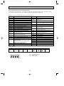
DATA
5-1. COOLING AND HEATING CAPACITY AND CHARACTERISTICS
5-1-1. Method for obtaining system cooling and heating capacity:
To obtain the system cooling and heating capacity and the electrical characteristics of the outdoor unit, first add up the ratings
of all the indoor units connected to the outdoor unit (see table below), and then use this total to find the standard capacity with
the help of the tables on page 11 to 14.
(1) Capacity of indoor unit
Model Number for indoor unit Model 20 Model 25 Model 32 Model 40 Model 50 Model 63 Model 71 Model 80 Model 100 Model 125
Model Capacity
kW
22
28
36
45
56
71
80
90
112
140
(2) Sample calculation
1
System assembled from indoor and outdoor unit (in this example the total capacity of the indoor units is greater than
that of the outdoor unit)
• Outdoor unit PUMY-P125YMA
• Indoor unit
PKFY-P25VAM-A o 2 , PLFY-P50VLMD-A o 2
2
According to the conditions in 1
, the total capacity of the indoor unit will be: 28 o 2 +
56 o 2 = 168
Capacity (kW)
Cooling
Heating
A
14.60
B
16.33
Outdoor unit power consumption (kW)
Cooling
Heating
6.04
5.14
Outdoor unit current (A)
Cooling
Heating
8.9
7.8
5-1-2. Method for obtaining the heating and cooling capacity of an indoor unit:
(1) The capacity of each indoor unit (kW) = the capacity A
(or B
model capacity
)o
total model capacity of all indoor units
(2) Sample calculation (using the system described above in 4-1-1. (2) ):
During cooling:
During heating:
• The total model capacity of the indoor unit is:
2.8 o 2 + 5.6 o 2=16.8kW
Therefore, the capacity of PKFY-P25VAM-A and
PLFY-P50VLMD-A will be calculated as follows by
using the formula in 4-1-2. (1):
• The total model capacity of indoor unit is:
3.2 o 2 + 6.3 o 2=19.0
Therefore, the capacity of PKFY-P25VAM-A and PLFYP50VLMD-A will be calculated as follows by using the
formula in 4-1-2. (1):
2.8
= 2.43kW
16.8
5.6
Model 50=14.6 o
= 4.87kW
16.8
3.2
= 2.75kW
19.0
6.3
Model 50=16.33 o
= 5.41kW
19.0
Model 25=14.6 o
Model 25=16.33 o
10
OC272A--1.qxp
03.9.4 11:06 AM
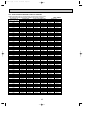
Page 11
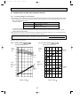
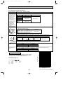
5-2. STANDARD CAPACITY DIAGRAM
5-2-1. PUMY-P125VMA STANDARD CAPACITY DIAGRAM
w Before calculating the sum of total capacity of indoor units, please convert
the valve into the kW model capacity following the formula on page 8.
Power consumption (kW)
Total capacity of
Capacity (kW)
w indoor units (kW)
Cooling
Cooling
Heating
Heating
2.58
2.86
70
7.00
7.88
2.61
2.89
71
7.10
8.00
2.65
2.93
72
7.20
8.11
2.69
2.97
73
7.30
8.22
2.73
3.01
74
7.40
8.33
2.76
3.04
75
7.50
8.44
2.80
3.08
76
7.60
8.56
2.84
3.12
77
7.70
8.67
2.88
3.16
78
7.80
8.78
2.92
3.20
79
7.90
8.89
2.96
3.23
80
8.00
9.00
3.00
3.27
81
8.10
9.10
3.04
3.31
82
8.20
9.20
3.08
3.35
83
8.30
9.30
3.12
3.39
84
8.40
9.40
3.16
3.43
85
8.50
9.50
3.20
3.47
86
8.60
9.60
3.25
3.51
87
8.70
9.70
3.29
3.55
88
8.80
9.80
3.33
3.59
89
8.90
9.90
3.38
3.64
90
9.00
10.00
3.42
3.68
91
9.10
10.10
3.47
3.72
92
9.20
10.22
3.51
3.76
93
9.30
10.33
3.56
3.80
94
9.40
10.45
3.60
3.85
95
9.50
10.56
3.65
3.89
96
9.60
10.67
3.69
3.93
97
9.70
10.79
3.74
3.98
98
9.80
10.90
3.79
4.02
99
9.90
11.02
3.84
4.06
100
10.00
11.13
3.89
4.11
101
10.10
11.24
3.93
4.15
102
10.20
11.36
3.98
4.20
103
10.30
11.47
4.03
4.24
104
10.40
11.59
4.08
4.29
105
10.50
11.70
4.13
4.33
106
10.60
11.81
4.19
4.38
107
10.70
11.93
4.24
4.42
108
10.80
12.04
4.29
4.47
109
10.90
12.16
4.34
4.52
110
11.00
12.27
4.39
4.56
111
11.10
12.38
4.45
4.61
112
11.20
12.50
4.50
4.66
113
11.30
12.63
4.55
4.70
114
11.40
12.75
4.61
4.75
115
11.50
12.88
4.66
4.80
116
11.60
13.00
4.72
4.85
117
11.70
13.13
4.77
4.90
118
11.80
13.25
4.83
4.94
119
11.90
13.38
4.89
4.99
120
12.00
13.50
4.94
5.04
121
12.10
13.63
5.00
5.09
122
12.20
13.75
5.06
5.14
123
12.30
13.88
5.12
5.19
124
12.40
14.00
5.17
5.24
125
12.50
14.13
11
240V, 50Hz
Current (A)
Cooling
Heating
12.2
11.0
12.3
11.1
12.5
11.3
12.6
11.5
12.8
11.6
13.0
11.8
13.1
11.9
13.3
12.1
13.5
12.3
13.6
12.4
13.8
12.6
13.9
12.8
14.1
12.9
14.3
13.1
14.5
13.3
14.6
13.5
14.8
13.6
15.0
13.8
15.1
14.0
15.3
14.2
15.5
14.4
15.7
14.6
15.8
14.8
16.0
15.0
16.2
15.1
16.4
15.3
16.6
15.5
16.8
15.7
16.9
15.9
17.1
16.1
17.3
16.3
17.5
16.6
17.7
16.8
17.9
17.0
18.1
17.2
18.3
17.4
18.5
17.6
18.6
17.8
18.8
18.0
19.0
18.3
19.2
18.5
19.4
18.7
19.6
18.9
19.8
19.2
20.0
19.4
20.2
19.6
20.4
19.9
20.7
20.1
20.9
20.3
21.1
20.6
21.3
20.8
21.5
21.1
21.7
21.3
21.9
21.5
22.1
21.8
22.3
22.0
OC272A--1.qxp
03.9.4 11:06 AM
Page 12
5-2-2. PUMY-P125VMA STANDARD CAPACITY DIAGRAM
w Before calculating the sum of total capacity of indoor units, please convert
the valve into the kW model capacity following the formula on page 8.
Power consumption (kW)
Capacity (kW)
Total capacity of
w indoor units (kW)
Cooling
Cooling
Heating
Heating
5.23
5.29
126
12.60
14.25
5.29
5.34
127
12.70
14.38
5.35
5.39
128
12.80
14.50
5.41
5.45
129
12.90
14.63
5.47
5.50
130
13.00
14.75
5.53
5.55
131
13.10
14.88
5.59
5.60
132
13.20
15.00
5.66
5.65
133
13.30
15.13
5.72
5.71
134
13.40
15.25
5.78
5.76
135
13.50
15.38
5.84
5.81
136
13.60
15.50
5.91
5.87
137
13.70
15.63
5.97
5.92
138
13.80
15.75
6.04
5.97
139
13.90
15.88
6.10
6.03
140
14.00
16.00
6.11
6.02
141
14.02
16.01
6.11
6.00
142
14.04
16.02
6.11
5.98
143
14.06
16.03
6.12
5.96
144
14.08
16.04
6.12
5.95
145
14.10
16.06
6.12
5.93
146
14.12
16.07
6.13
5.91
147
14.15
16.08
6.13
5.90
148
14.17
16.09
6.13
5.88
149
14.19
16.10
6.14
5.86
150
14.21
16.12
6.14
5.85
151
14.23
16.13
6.14
5.83
152
14.25
16.14
6.15
5.81
153
14.27
16.15
6.15
5.79
154
14.30
16.16
6.15
5.78
155
14.32
16.17
6.15
5.76
156
14.34
16.19
6.16
5.74
157
14.36
16.20
6.16
5.73
158
14.38
16.21
6.16
5.71
159
14.40
16.22
6.17
5.69
160
14.42
16.23
6.17
5.68
161
14.45
16.25
6.17
5.66
162
14.47
16.26
6.18
5.64
163
14.49
16.27
6.18
5.62
164
14.51
16.28
6.18
5.61
165
14.53
16.29
6.19
5.59
166
14.55
16.31
6.19
5.57
167
14.57
16.32
6.19
5.56
168
14.60
16.33
6.20
5.54
169
14.62
16.34
6.20
5.52
170
14.64
16.35
6.20
5.51
171
14.66
16.36
6.21
5.49
172
14.68
16.38
6.21
5.47
173
14.70
16.39
6.21
5.46
174
14.72
16.40
6.22
5.44
175
14.75
16.41
6.22
5.42
176
14.77
16.42
6.22
5.40
177
14.79
16.44
6.22
5.39
178
14.81
16.45
6.23
5.37
179
14.83
16.46
6.23
5.35
180
14.85
16.47
6.23
5.34
181
14.87
16.48
6.24
5.32
182
14.89
16.50
12
240V, 50Hzw
Current (A)
Cooling
Heating
22.6
22.3
22.8
22.5
23.0
22.8
23.2
23.1
23.4
23.3
23.6
23.6
23.9
23.8
24.1
24.1
24.3
24.4
24.5
24.6
24.8
24.9
25.0
25.2
25.2
25.4
25.4
25.7
25.7
26.0
25.6
26.0
25.6
26.0
25.5
26.0
25.4
26.1
25.3
26.1
25.3
26.1
25.2
26.1
25.1
26.1
25.0
26.1
25.0
26.1
24.9
26.2
24.8
26.2
24.8
26.2
24.7
26.2
24.6
26.2
24.5
26.2
24.5
26.2
24.4
26.2
24.3
26.3
24.3
26.3
24.2
26.3
24.1
26.3
24.0
26.3
24.0
26.3
23.9
26.3
23.8
26.4
23.7
26.4
23.7
26.4
23.6
26.4
23.5
26.4
23.5
26.4
23.4
26.4
23.3
26.5
23.2
26.5
23.2
26.5
23.1
26.5
23.0
26.5
23.0
26.5
22.9
26.5
22.8
26.5
22.7
26.6
22.7
26.6
OC272A--1.qxp
03.9.4 11:06 AM
Page 13
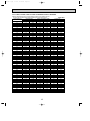
5-2-3. PUMY-P125YMA, PUMY-P125YMA1 STANDARD CAPACITY DIAGRAM
w Before calculating the sum of total capacity of indoor units, please convert
the valve into the kW model capacity following the formula on page 8.
Power consumption (kW)
Total capacity of
Capacity (kW)
w indoor units (kW)
Cooling
Cooling
Heating
Heating
2.47
2.63
70
7.00
7.88
2.50
2.66
71
7.10
8.00
2.54
2.70
72
7.20
8.11
2.57
2.73
73
7.30
8.22
2.61
2.77
74
7.40
8.33
2.64
2.80
75
7.50
8.44
2.68
2.84
76
7.60
8.56
2.72
2.87
77
7.70
8.67
2.76
2.91
78
7.80
8.78
2.80
2.94
79
7.90
8.89
2.83
2.98
80
8.00
9.00
2.87
3.02
81
8.10
9.10
2.91
3.05
82
8.20
9.20
2.95
3.09
83
8.30
9.30
2.99
3.13
84
8.40
9.40
3.03
3.16
85
8.50
9.50
3.07
3.20
86
8.60
9.60
3.12
3.24
87
8.70
9.70
3.16
3.27
88
8.80
9.80
3.20
3.31
89
8.90
9.90
3.24
3.35
90
9.00
10.00
3.29
3.39
91
9.10
10.10
3.33
3.43
92
9.20
10.22
3.37
3.47
93
9.30
10.33
3.42
3.51
94
9.40
10.45
3.46
3.55
95
9.50
10.56
3.51
3.59
96
9.60
10.67
3.55
3.62
97
9.70
10.79
3.60
3.67
98
9.80
10.90
3.65
3.71
99
9.90
11.02
3.69
3.75
100
10.00
11.13
3.74
3.79
101
10.10
11.24
3.79
3.83
102
10.20
11.36
3.84
3.87
103
10.30
11.47
3.88
3.91
104
10.40
11.59
3.93
3.95
105
10.50
11.70
3.98
3.99
106
10.60
11.81
4.03
4.04
107
10.70
11.93
4.08
4.08
108
10.80
12.04
4.13
4.12
109
10.90
12.16
4.18
4.16
110
11.00
12.27
4.24
4.21
111
11.10
12.38
4.29
4.25
112
11.20
12.50
4.34
4.30
113
11.30
12.63
4.39
4.34
114
11.40
12.75
4.44
4.38
115
11.50
12.88
4.50
4.43
116
11.60
13.00
4.55
4.47
117
11.70
13.13
4.61
4.52
118
11.80
13.25
4.66
4.56
119
11.90
13.38
4.72
4.61
120
12.00
13.50
4.77
4.65
121
12.10
13.63
4.83
4.70
122
12.20
13.75
4.88
4.74
123
12.30
13.88
4.94
4.79
124
12.40
14.00
5.00
4.84
125
12.50
14.13
13
415V, 50Hz
Current (A)
Cooling
Heating
4.2
3.8
4.2
3.9
4.3
3.9
4.3
4.0
4.4
4.0
4.4
4.1
4.5
4.1
4.5
4.2
4.5
4.2
4.6
4.3
4.7
4.3
4.7
4.4
4.8
4.4
4.8
4.5
4.9
4.6
4.9
4.6
5.0
4.7
5.1
4.8
5.1
4.8
5.2
4.9
5.2
5.0
5.3
5.0
5.4
5.1
5.4
5.2
5.5
5.2
5.5
5.2
5.5
5.3
5.6
5.4
5.7
5.4
5.7
5.5
5.8
5.6
5.9
5.7
5.9
5.7
6.0
5.8
6.0
5.9
6.1
5.9
6.2
6.0
6.2
6.1
6.3
6.2
6.4
6.2
6.4
6.3
6.4
6.3
6.5
6.4
6.6
6.5
6.6
6.6
6.7
6.6
6.8
6.7
6.8
6.8
6.9
6.9
7.0
7.0
7.0
7.1
7.1
7.1
7.2
7.2
7.2
7.3
7.3
7.4
7.4
7.5
OC272A--1.qxp
03.9.4 11:06 AM
Page 14
5-2-4. PUMY-P125YMA, PUMY-P125YMA1 STANDARD CAPACITY DIAGRAM
w Before calculating the sum of total capacity of indoor units, please convert
the valve into the kW model capacity following the formula on page 8.
Power consumption (kW)
Capacity (kW)
Total capacity of
w indoor units (kW)
Cooling
Cooling
Heating
Heating
5.05
4.88
126
12.60
14.25
5.11
4.93
127
12.70
14.38
5.17
4.98
128
12.80
14.50
5.23
5.03
129
12.90
14.63
5.29
5.07
130
13.00
14.75
5.35
5.12
131
13.10
14.88
5.41
5.17
132
13.20
15.00
5.47
5.22
133
13.30
15.13
5.53
5.27
134
13.40
15.25
5.59
5.32
135
13.50
15.38
5.65
5.36
136
13.60
15.50
5.71
5.41
137
13.70
15.63
5.77
5.46
138
13.80
15.75
5.84
5.51
139
13.90
15.88
5.95
5.58
140
14.00
16.00
5.96
5.57
141
14.02
16.01
5.96
5.55
142
14.04
16.02
5.96
5.53
143
14.06
16.03
5.97
5.52
144
14.08
16.04
5.97
5.50
145
14.10
16.06
5.97
5.49
146
14.12
16.07
5.98
5.47
147
14.15
16.08
5.98
5.46
148
14.17
16.09
5.98
5.44
149
14.19
16.10
5.99
5.43
150
14.21
16.12
5.99
5.41
151
14.23
16.13
5.99
5.39
152
14.25
16.14
5.99
5.38
153
14.27
16.15
6.00
5.36
154
14.30
16.16
6.00
5.35
155
14.32
16.17
6.00
5.33
156
14.34
16.19
6.01
5.32
157
14.36
16.20
6.01
5.30
158
14.38
16.21
6.01
5.28
159
14.40
16.22
6.02
5.27
160
14.42
16.23
6.02
5.25
161
14.45
16.25
6.02
5.24
162
14.47
16.26
6.03
5.22
163
14.49
16.27
6.03
5.21
164
14.51
16.28
6.03
5.19
165
14.53
16.29
6.03
5.17
166
14.55
16.31
6.04
5.16
167
14.57
16.32
6.04
5.14
168
14.60
16.33
6.04
5.13
169
14.62
16.34
6.05
5.11
170
14.64
16.35
6.05
5.10
171
14.66
16.36
6.05
5.08
172
14.68
16.38
6.06
5.06
173
14.70
16.39
6.06
5.05
174
14.72
16.40
6.06
5.03
175
14.75
16.41
6.07
5.02
176
14.77
16.42
6.07
5.00
177
14.79
16.44
6.07
4.99
178
14.81
16.45
6.07
4.97
179
14.83
16.46
6.08
4.95
180
14.85
16.47
6.08
4.94
181
14.87
16.48
6.08
4.92
182
14.89
16.50
14
415V, 50Hzw
Current (A)
Cooling
Heating
7.5
7.6
7.5
7.6
7.5
7.7
7.6
7.7
7.7
7.8
7.7
7.9
7.8
8.0
7.9
8.1
8.0
8.2
8.0
8.3
8.1
8.4
8.2
8.5
8.3
8.5
8.3
8.6
8.4
8.8
8.4
8.8
8.4
8.8
8.4
8.8
8.3
8.8
8.3
8.8
8.3
8.8
8.3
8.9
8.3
8.9
8.2
8.9
8.2
8.9
8.2
8.9
8.2
8.9
8.1
8.9
8.1
8.9
8.1
8.9
8.1
8.9
8.0
8.9
8.0
8.9
8.0
8.9
8.0
8.9
7.9
8.9
7.9
8.9
7.9
8.9
7.9
8.9
7.8
8.9
7.8
8.9
7.8
8.9
7.8
8.9
7.8
8.9
7.8
9.0
7.8
9.0
7.8
9.0
7.7
9.0
7.7
9.0
7.7
9.0
7.7
9.0
7.6
9.0
7.6
9.0
7.6
9.0
7.6
9.0
7.6
9.0
7.5
9.0
OC272A--1.qxp
03.9.4 11:06 AM
Page 15
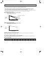
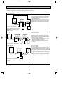
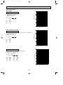
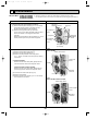
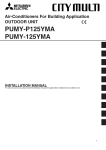
5-3. CORRECTING COOLING AND HEATING CAPACITY
5-3-1. Correcting Changes in Air Conditions
(1)The performance curve charts (Figure 1, 2) show the rated capacity (total capacity) under the stated conditions when standard
length for piping (5m) is used. The rated power is derived from the capacity ratio and power ratio obtained for the indoor and
outdoor intake temperatures at time 1.
• Standard conditions:
Service Ref.
PUMY-P125VMA PUMY-P125YMA PUMY-P125YMA1
Indoor D.B. 27°C / W.B. 19°C
Rated cooling capacity
Outdoor D.B. 35°C
Indoor D.B. 20°C
Rated heating capacity
Outdoor D.B. 7°C / W.B. 6°C
• Use the rated capacity and rated power values given in the characteristics table for each indoor unit.
• The capacity is the single value on the side of the outdoor unit; the capacity on the sides of each indoor unit must be
added to obtain the total capacity.
(2)The capacity of each indoor unit may be obtained by multiplying the total capacity obtained in (1) by the ratio between the
individual capacity at the rated time and the total capacity at the rated time.
Individual capacity under stated conditions = total capacity under the stated conditions o
individual capacity at the rated time
total capacity at the rated time
(3)Capacity correction factor curve
Figure 2. PUMY-P125VMA PUMY-P125YMA
PUMY-P125YMA1
Heating performance curve
Figure 1. PUMY-P125VMA PUMY-P125YMA
PUMY-P125YMA1
Cooling performance curve
1.4
1.4
Cooling
Heating
Capacity 1.2
(ratio)
Capacity 1.2
(ratio)
15
1.0
25
22
20
18
16
INDOOR
1.0
0.8
20
INDOOR
<D.B. :>
0.8
<W.B. :>
0.6
0.6
Heating
1.4
Power
22
20
18
16
INDOOR
1.2
consumption
(ratio)
1.4
Power
Cooling
1.0
consumption
<W.B. :>
0.8
1.2
(ratio)
20
15 INDOOR
1.0
25
0.8
0.6
0.6
0.4
-12 -10
0.4
-5
0
10
20
30
40 46
Outdoor <D.B. :>
-5
0
5
Outdoor <W.B. :>
15
10
15
<D.B. :>
OC272A--1.qxp
03.9.4 11:06 AM
Page 16
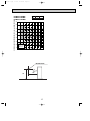
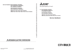
5-3-2. Correcting Capacity for Changes in the Length of Refrigerant Piping
(1) During cooling, to obtain the ratio (and the equivalent piping length) of the outdoor units rated capacity and the total
in-use indoor capacity, first find the capacity ratio corresponding to the standard piping length (5m) from Figures 3
at first, and then multiply by the cooling capacity from Figure 1 to obtain the actual capacity.
(2) During heating, to find the equivalent piping length, first find the capacity ratio corresponding to standard piping length (5m)
from Figure 4, and then multiply by the heating capacity from Figure 2 to obtain the actual capacity.
(1) Cooling capacity correction factor
Figure 3. PUMY-P125VMA PUMY-P125YMA PUMY-P125YMA1
Cooling capacity correction curve
1.0
Total capacity for indoor unit
0.95
63 (50%)
Cooling 0.9
Capacity
0.85
(ratio)
94 (75%)
125 (100%)
163 (130%)
0.8
5 10 15 20 25 30 35 40 45 50 55
piping length (m)
(2) Heating capacity correction factor
Figure 4. PUMY-P125VMA PUMY-P125YMA PUMY-P125YMA1
Heating capacity correction curve
1.0
Heating
Capacity
(ratio)
0.95
0.9
5 10 15 20 25 30 35 40 45 50 55
piping length (m)
(3) Method for Obtaining the Equivalent Piping Length
Equivalent length for type 125 = (length of piping to farthest indoor unit) + (0.35 o number of bends in the piping) (m)
Length of piping to farthest indoor unit: type 125.....70m
5-3-3. Correction of Heating Capacity for Frost and Defrosting
If heating capacity has been reduced due to frost formation or defrosting, multiply the capacity by the appropriate correction
factor from the following table to obtain the actual heating capacity.
Correction factor diagram
Outdoor Intake temperature (W.B.°C)
Correction factor
6
1.0
4
0.98
2
0.89
0
0.88
16
-2
0.89
-4
0.9
-6
0.95
-8
0.95
-10
0.95
03.9.4 11:06 AM
Page 17
PUMY-P125VMA
PUMY-P125YMA
PUMY-P125YMA1
OCTAVE BAND SOUND PRESSURE LEVEL, dB re 0.0002 MICRO BAR
OC272A--1.qxp
NOTCH SPL(dB)
Hi
54
LINE
90
80
70
NC-70
60
NC-60
50
NC-50
40
NC-40
30
NC-30
20
10
APPROXIMATE
THRESHOLD OF
HEARING FOR
CONTINUOUS
NOISE
63
NC-20
125 250 500 1000 2000 4000 8000
BAND CENTER FREQUENCIES, Hz
MICROPHONE
1m
1m
17
18
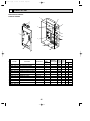
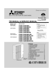
Drain hole
(3-{33 hole)
shaped notched holes
(standard bolt M10)
Knock out holes for power line 2-{29
Knock out hole for right piping
Liquid refrigerant pipe
connection {9.52 (3/8F)
Gas refrigerant-pipe
connection {19.05 (3/4F)
Knock out holes for
power line 2-{27
Bottom piping hole
Knock out hole for
front piping
Oval holes
(standard bolt M10)
Piping cover
Handle for
moving
Optional parts
installation hole
✻1...Indicates the dimensions of the cutoff valve connector.
✻2...Make sure that the panel can be easily removed for maintenance
when a piping cover is used for aesthetic reasons.
Rear piping hole
Rear air intake
Side air intake
Optional parts
(base branching
pipe) installation
hole
• OUTDOOR UNITS
PUMY-P125VMA
PUMY-P125YMA
PUMY-P125YMA1
Terminal block for power source
Terminal block for central control
Terminal block for transmission
03.9.4 11:06 AM
Handle for moving
Air outlet
6
Air intake
OC272A--1.qxp
Page 18
OUTLINES AND DIMENSIONS
unit : mm
OC272A--1.qxp
03.9.4 11:06 AM
7
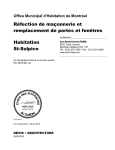
Page 19
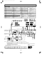
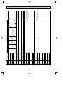
WIRING DIAGRAM
PUMY-P125VMA
SYMBOL
TB1
TB3
TB7
CE
C1,C2
NAME
SYMBOL
NAME
SYMBOL
NAME
SYMBOL
NAME
Magnetic Contactor
N.F.
Noise Filter Circuit Board
CNS1 Connector(Multi system)
Terminal Block(Power Supply) 52C
LI/LO Connection Lead(L-Phase)
CNS2 Connector(Centralized Control)
Terminal Block(Transmission) 21S4 4-Way Valve
Terminal Block(Centralized Control)
Solenoide Valve(Hot Gas Bypass) NI/NO Connection Lead(N-Phase)
SV
CN4 Connector
Connection Terminal(Ground)
LEV(A) Expansion Valve
CN40 Connector(Centralized Control Power Supply)
EI
Smoothing Capacitor
CNAC2 Connector
CN41 Connector(For String Jumper Connector)
Fan Motor Capacitor
MF1,MF2 Fan Motor(Inner Thermostat)
DCL1~4 Reactor
MC
Compressor(Inner Thermostat) CN5 Connector
CN51 Connector(Connected for Option)
Compressor drive signal,Error signal
Resistor(Rush Current Protection)
RS
ACTM Active Filter Module
P.B.
Power Circuit Board
M.B. Multi Circuit Board
CN3D Connector(Connected for Option)
Auto Change Over Signal
Thermistor(Discharge Temperature Detection) U/V/W Connection Terminal(U/V/W Phase) F1,F2 Fuse(6.3A)
TH1
CN2~6 Connector
TH2
SW1 Switch(Display Selection)
CN3S Connector(Connected for Option)
Thermistor
Demand Signal
(Low Pressure Saturated Temp.Detection) CNDC Connector
SW2 Switch(Function Selection)
CNAF Connector
SW3 Switch(Test Run)
TH5
X500 Relay(Magnetic Contactor)
Thermistor
(Pipe Temp.Detection / Judging Defrost) IGBT Converter,Inverter
SW4 Switch(Model Selection)
X501 Relay(4-Way Valve)
Thermistor(Outdoor Temp.Detection) LED1 Light Emitting Diode(Inverter Control Status) SW5 Switch(Function Selection)
TH6
X502 Relay(Solenoid Valve)
SW5-1 Auto Change Over
OFF;disabled ON;enabled
THHS A/B Thermistor(Radiator Panel) A;ACTM,B;IGBT SC-S,R Screw Type Terminal(L./N-Phase)
LED1,2 Digital Indication LED
Operation Inspection Indication
SC-P1,P2 Screw Type Terminal(DC Voltage) SW6 Switch(Function Selection)
63HS High Pressuer Sensor
(Discharge Pressure Detection)
SC-N1,N2 Screw Type Terminal(DC Voltage) SWU1 Switch(Unit Address Selection,1st digit)
SWU2 Switch(Unit Address Selection,2nd digit)
49C
Thermal Switch(Compressor)
M1
*1 The address automatically
becomes "100" if it is
LEV
set as "01~50".
BRN
M2
BRN
TB3
TB7
M1
ORN
M2
ORN
78
456
POWER SUPPLY
~/N
220-230-240V N
1 3 MF1
6 5 4 3 2 1
3 1
3 2 1
3 2 1
MF2 1 3
(WHT)
LEV-A (WHT) 49C(GRY) CN3S(WHT) CN3D(WHT) (WHT)
CN51
LED1
LED2
CNS1
1
2
(WHT) 2
F.C
1 (RED)
52C(ORG)
3 3.12V
4 4.COMP. ON
1 YLW
2 CNS2
5
(YLW)
5.Error
3 YLW 52C
1
X500
01
01
9
9
*1
21S4(GRN)
SW4
2 TH2
1 BLU
ON
1 (WHT)
3 BLU 21S4
SWU2
SWU1
OFF
1 2 3 4
1 2 3 4
X501
(2nd
digit)
(1st
digit)
TH5
1
2
3
4
CN41(WHT)
CN40(WHT)
2
SV(BLK)
1 (GRN)
SW1
SW5
1 BLK
ON
ON
3 BLK SV1
TH6
2
X502
OFF
OFF
1 (RED)
CH(BLU)
12345678
12345678
1
2 TH1
SW3
SW2
SW6
3
1 (WHT)
ON
ON
ON
F1
F2
OFF
OFF
OFF
(6.3A)
(6.3A)
3 63HS
12345678
12
1 2 3 4 5 6 7 8 910
2 (WHT)
1 3 CNAC
CN4
1
(RED)
(WHT) CNDC(PNK) CN2 (WHT)
3 1
1 2 3 4 5 6 7
2 1
TH2
TB1
23
NO FUSE BREAKER 32A
L
L
TH5
N
TH6
TH1
63HS
BLU
WHT
23
S
BLU
WHT
YLW
78
< M.B.>
1 3
1 3
YLW
S
FOR CENTRALIZED
CONTROL
DC 30V (Non-polar)
WHT
49C
6
456
TO INDOOR UNIT
CONNECTING WIRES
DC 30V (Non-polar)
RED
RED
C2
C2
MF1
ORN
ORN
BLU
BLU
WHT
MF2
7
CN5 2 1
(RED)
1
3
3 CNAC2
(RED)
LI
LO
NI
NO
2 CN4
1 (WHT)
THHS_A
EI
2 CN3
1 (WHT)
2 CN6
1 (WHT)
< N.F.>
THHS_B
1 CNDC 6 5 4 3 2 1 7 6 5 4 3 2 1
(PNK) CNAF (WHT)
CN2 (WHT)
< P.B.>
IGBT
+
-
W
BLK
V
WHT
U
RED
MC
DCL4
2 CN5
1 (RED)
DCL3
DCL2
DCL1
RS
1 2 3 4 5 6
SCR-S
SCR-R
52C
L1
+
L2
LED1
SCR-N1
P
+
N1
N2
I
-
SCR-P1
+
CE
SCR-P2
+
SCR-N2
ACTM
NOTES: 1. Refer to the wiring diagrams of the indoor units for details on wiring of each indoor unit.
2. Symbols used in wiring diagram above are. :Terminal block,
:Connector, :Insertion tab.
3. Self-diagnosis function
The indoor and outdoor units can be diagnosed automatically using the self-diagnosis switch(SW1) and LED1,2
(LED indication)found on the multi-controller of the outdoor unit.
LED indication : Set all contacts of SW1 to OFF.
4. For the system utilizing R-converter units(PAC-SF29LB),the following functions are not available.
SW3;TEST RUN SW5-1;AUTO CHANGE OVER CN3D;AUTO CHANGE OVER(external singnal)
5. The input for CN3D 1-2(AUTO CHANGE OVER EXTERNAL SIGNEL)is as follows.
Short;heating Open;Cooling(It differs from Service ref.PUMY-P125YMA)
(Example)
•During normal operation
When the compressor and SV1 are
The LED indicates the drive state of the controller in the outdoor unit.
turned during cooling operation.
Bit
Indication
1
Compressor
operated
2
52C
3
21S4
4
SV1
5
-
6
-
7
-
8
Always lit
1
23
•When fault requiring inspection has occurred
The LED alternately indicates the inspection code and the location of the unit in which the fault has occurred.
19
45
67
8
OC272A--1.qxp
03.9.4 11:06 AM
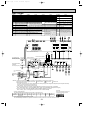
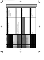
Page 20
PUMY-P125YMA
SYMBOL
ACCT
SYMBOL
NAME
CONNECTOR <CURRENT DETECTION> C1,C2
SYMBOL
NAME
FAN MOTOR CAPACITOR
SV1
SYMBOL
NAME
SOLENOID VALVE <HOT GAS BYPASS> TH2
CB1,CB2 SMOOTHING CAPACITOR
DM
DIODE MODULE
SW1
SWITCH <DISPLAY SELECTION>
CNA
DCL
REACTOR
SW2
SWITCH <FUNCTION SELECTION> TH5
FAN CONTROL
SW3
SWITCH <TEST RUN>
FUSE (6.3A)
SW4
SWITCH <MODEL SELECTION>
CONNECTOR <POWER SUPPLY>
NAME
THERMISTOR
<LOW PRESSURE SATURATED
TEMPERATURE DETECTION>
THERMISTOR
<PIPE TEMPERATURE DETECTION
• JUDGING DEFROST>
THERMISTOR
CNR
CONNECTOR <DISCHARGE CIRCUIT, POWER SUPPLY> F.C
CNS1
CONNECTOR <MULTI SYSTEM>
CNS2
CONNECTOR <CENTRALIZED CONTROL> FUSE2
FUSE (2A)
SW5
SWITCH <FUNCTION SELECTION>
<OUTDOOR TEMPERATURE DETECTION>
CN1
CONNECTOR <CONTROLLER DRIVE CONTROL> IPM
INTELLIGENT POWER MODULE
SWU1
SWITCH <UNIT ADDRESS SELECTION,1ST DIGIT> X
RELAY
CN2
CONNECTOR <POWER SYNC SIGNAL, PROTECTION> LD1
SWITCH <UNIT ADDRESS SELECTION,2ND DIGIT> X71
RELAY <MAGNETIC CONTACTOR>
CN3
CONNECTOR <POWER SUPPLY 30V,12V,5V>
SWU2
DIGITAL INDICATION LED
<OPERATION INSPECTION INDICATION>
SWU3
SWITCH <UNIT ADDRESS SELECTION,3RD DIGIT> X72
RELAY <4-WAY VALVE>
CN4
CONNECTOR <INVERTER SIGNAL 5V> MC
COMPRESSOR <INNER THERMOSTAT> TB1
TERMINAL BLOCK <POWER SUPPLY> X73
RELAY <SOLENOID VALVE>
CN40
CONNECTOR <CENTRALIZED CONTROL POWER SUPPLY> MF1,MF2 FAN MOTOR <INNER THERMOSTAT> TB3
TERMINAL BLOCK <TRANSMISSION> ZNR
VARISTOR
CN41
CONNECTOR <FOR STORING JUMPER CONNECTOR> NF
NOISE FILTER
TERMINAL BLOCK <CENTRALIZED CONTROL> 21S4
4-WAY VALVE
CN51
CONNECTOR <COMPRESSOR DRIVE SIGNAL OUTPUT> RS1
RESISTOR <RUSH CURRENT PROTECT> THHS
THERMISTOR
<IPM RADIATOR PANEL
TEMPERATURE DETECTION>
THERMISTOR
<DISCHARGE TEMPERATURE
DETECTION>
49C
THERMAL SWITCH <COMPRESSOR>
52C
MAGNETIC CONTACTOR
63HS
HIGH PRESSURE SENSOR
<DISCHARGE PRESSURE DETECTION>
FUSE1
TB7
CN3D
CONNECTOR <AUTO CHANGE OVER SIGNAL> RB1,RB2 RESISTOR <VOLTAGE BALANCE ADJUSTMENT>
CN3S
CONNECTOR <DEMAND SIGNAL> RD1,RD2 RESISTOR <DISCHARGE>
SLEV
C01,C02 SMOOTHING CAPACITOR
C03
TH1
EXPANSION VALVE
TH6
CAPACITOR <FILTER>
THHS TH6
TH5
TH2
TH1
63HS
SLEV
6
3
1 2 3 4
CN40
(WHT)
1 2 3 4
CN41
(WHT)
1 2 3 4 5
CN51
(WHT)
LD1
1 2 3
CN3D
(WHT)
1 2 3
CN3S
(RED)
1 2 1 3 1 2
THHS TH6 TH5
(BLK) (WHT)(GRN)
SW1
ON
1 CNS2
2 (YLW)
1 3 1 2 1 2 3 1 2 3 4 5 6
SLEV
TH2 TH1 63HS
(WHT)
(GRN)(WHT) (WHT)
SW2
ON
OFF
78
78
4 56
4 56
SWU3
90 1
SWU2
OFF
23
23
78
90 1
4 56
90 1
23
1 CNS1
2 (RED)
OFF
12345678
SW3
SW4
ON
ON
SWU1
(3rd digit)(2nd digit) (1st digit)
1 2 3 4 5 6 7 8 9 10
SW5
ON
OFF
OFF
1234
12345678
12
(RED)
(YLW)
(WHT)
CN2
CN3
CN1
6 3 2 1 6 5 4 3 2 1 7 6 3 2 1 7 6
ACCT 2
(YLW) 1
(YLW)
CN4
5 4 3 2 1
<MULTI CONTROLLER BOARD>
49C
MC
U
L2
WHT
L3
BLK
LI3 LO3
N
BLU
N
+
ZNR
~
BLK
~
–
E
GROUND
WHT
BLU
X72
X73
SV1
BLU
WHT
21S4
3 1
3 1
BLU
WHT
(WHT) (WHT)
(BLU)
(BLK)
(GRN)
MF1
MF2
52C
SV1
21S4
3 1
3 1
3 1
3 1
BLU
WHT
3 1
52C
BLK
~
MF1
+
CB1
–
+
CB2
–
MF2
C1
C2
52C
GRN
GRN/YLW
E
X71
BLU
WHT
3 1
NF
CNA
(RED)
RED
LI1 LO1
WHT
LI2 LO2
DCL
N
F.C
FUSE1
(6.3A)
RED
ORN
NO FUSE BREAKER TB1
25A
L1
L1
RED
BLK
P1
7 6 5 4 3 2 1
CN4
(YLW)
RED
ORN
DM
7
7 6 3 2 1
CN3
(WHT)
BLK
BLK
6
P
BLU
S
C02
6 5 4 3 2 1
CN2
(YLW)
BLU
BLU
N1
YLW
YLW
ORN
C01
GRN
(RED)
(WHT)
3 1 CNA 10 8 6 5 3 1 CNR
FUSE2
(2A)
WHT
RS1
ORN
+
-
RB2 RB1
BLU
X
3 1 6 3 2 1
49C
CN1
(YLW) (RED)
RED
(WHT)
CNR
1
3
5
6
8
10
X
N
IPM
C03
YLW
YLW
W
+
-
RD2
5
YLW
YLW
BLK
V
P
BLK
BRN
TB7
POWER SUPPLY L2
L3
3N~
380/220-415/240V N
50Hz
U
RD1
S
FOR CENTRALIZED M1
CONTROL
M2
DC 30V (Non-polar)
WHT
<POWER SUPPLY BOARD>
<RESISTOR BOARD>
6
V
RED
TB3
BRN
M1
TO INDOOR UNIT
CONNECTING WIRES M2
DC 30V (Non-polar)
4
W
NOTES : 1. Refer to the wiring diagrams of the indoor units for details on wiring of each indoor unit.
2. Symbols used in wiring diagram above are. : Terminal block,
: Connector, :Insertion tab.
3. Self-diagnosis function
The indoor and outdoor units can be diagnosed automatically using the self-diagnosis switch (SW1) and LD1(LED indication)
found on the multi-controller of the outdoor unit.
LED indication : Set all contacts of SW1 to OFF.
(Example)
When the compressor and SV1 are
turned during cooling operation.
•During normal operation
The LED indicates the drive state of the controller in the outdoor unit.
Bit
Indication
1
Compressor
operated
2
52C
3
21S4
4
SV1
5
-
6
-
1
7
-
23
8
Always lit
•When fault requiring inspection has occurred
The LED alternately indicates the inspection code and the location of the unit in which the fault has occurred.
20
45
67
8
OC272A--1.qxp
03.9.4 11:06 AM
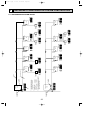
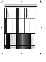
Page 21
PUMY-P125YMA1
SYMBOL
ACCT
CB1,CB2
CNA
CNR
CNS1
CNS2
CN1
CN2
CN3
CN4
CN40
CN41
CN51
CN3D
CN3S
C01,C02
C03
SYMBOL
NAME
CONNECTOR <CURRENT DETECTION> C1,C2
SMOOTHING CAPACITOR
DM
CONNECTOR <POWER SUPPLY> DCL
CONNECTOR <DISCHARGE CIRCUIT,POWER SUPPLY> F.C
CONNECTOR <MULTI SYSTEM> FUSE1
CONNECTOR <CENTRALIZED CONTROL> FUSE2
CONNECTOR <CONTROLLER DRIVE CONTROL> IPM
CONNECTOR <POWER SYNC SIGNAL,PROTECTION> LD1
CONNECTOR <POWER SUPPLY 30V,12V,5V>
CONNECTOR <INVERTER SIGNAL 5V> MC
CONNECTOR <CENTRALIZED CONTROL POWER SUPPLY> MF1,MF2
CONNECTOR <FOR STORING JUMPER CONNECTOR> NF
CONNECTOR <COMPRESSOR DRIVE SIGNAL OUTPUT> RS1
CONNECTOR <AUTO CHANGE OVER SIGNAL> RB1,RB2
CONNECTOR <DEMAND SIGNAL> RD1,RD2
SLEV
SMOOTHING CAPACITOR
CAPACITOR <FILTER>
SYMBOL
NAME
SOLENOID VALVE <HOT GAS BYPASS> TH2
SWITCH <DISPLAY SELECTION>
SWITCH <FUNCTION SELECTION> TH5
SWITCH <TEST RUN>
SWITCH <MODEL SELECTION> TH6
SWITCH <FUNCTION SELECTION>
SW5-1 AUTO CHANGE OVER X
OFF : disabled ON : enabled X71
DIGITAL INDICATION LED
<OPERATION INSPECTION INDICATION> SWU1 SWITCH <UNIT ADDRESS SELECTION,1ST DIGIT> X72
COMPRESSOR <INNER THERMOSTAT> SWU2 SWITCH <UNIT ADDRESS SELECTION,2ND DIGIT> X73
FAN MOTOR <INNER THERMOSTAT> SWU3 SWITCH <UNIT ADDRESS SELECTION,3RD DIGIT> ZNR
NOISE FILTER
TERMINAL BLOCK <POWER SUPPLY> 21S4
TB1
TERMINAL BLOCK <TRANSMISSION> 49C
RESISTOR <RUSH CURRENT PROTECT> TB3
TERMINAL BLOCK <CENTRALIZED CONTROL> 52C
RESISTOR <VOLTAGE BALANCE ADJUSTMENT> TB7
63HS
RESISTOR <DISCHARGE>
THHS THERMISTOR
<IPM RADIATOR PANEL TEMP. DETECTION>
EXPANSION VALVE
NAME
FAN MOTOR CAPACITOR
DIODE MODULE
REACTOR
FAN CONTROL
FUSE (6.3A)
FUSE (2A)
INTELLIGENT POWER MODULE
SYMBOL
SV1
SW1
SW2
SW3
SW4
SW5
NAME
THERMISTOR
<LOW PRESSURE SATURATED TEMP. DETECTION>
THERMISTOR
<PIPE TEMP. DETECTION • JUDGING DEFROST>
THERMISTOR
<OUTDOOR TEMP. DETECTION>
RELAY
RELAY <MAGNETIC CONTACTOR>
RELAY <4-WAY VALVE>
RELAY <SOLENOID VALVE>
VARISTOR
4-WAY VALVE
THERMAL SWITCH <COMPRESSOR>
MAGNETIC CONTACTOR
HIGH PRESSURE SENSOR
<DISCHARGE PRESSURE DETECTION>
THERMISTOR
<DISCHARGE TEMP. DETECTION>
TH1
THHS
TH6
TH5
TH2
TH1
63HS
SLEV
3
1 2 3 4
CN40
1 2 3 4
CN41
1 2 3 4 5
CN51
1 2 3
CN3D
1 2 3
CN3S
1 2
1 3
THHS TH6
(WHT)
(WHT)
(WHT)
(WHT)
(WHT)
(BLK)
1 2
TH5
1 3
TH2
(WHT) (GRN)
SW1
LD1
78
456
78
78
456
SWU2
23
23
23
456
SWU3
901
1 2 3 4 5 6 7 8 9 10
SW4
SW5
ON
ON
ON
OFF
OFF
OFF
12
1234
(RED)
ACCT 2
(YLW) 1
12345678
(YLW)
CN2
6 5 4 3 2 1
CN1
6 3 2 1
SWU1
(3rd digit)(2nd digit)(1st digit)
(WHT)
OFF
12345678
SW3
901
1 2 3 4 5 6
SLEV
(WHT)
ON
OFF
901
1 2 3
63HS
SW2
ON
1 CNS2
2 (YLW)
1 CNS1
2 (RED)
1 2
TH1
(GRN) (WHT)
6
(WHT)
CN3
7 6 3 2 1
(YLW)
CN4
7 6 5 4 3 2 1
<MULTI CONTROLLER BOARD>
49C
MC
U
4
W
6
5
7
U
V
W
RD1
P
(WHT)
(WHT)
N1
YLW
YLW
S
7 6 5 4 3 2 1
CN4
(WHT)
(YLW)
6
P
C02
P1
FUSE2
(2A)
N
E
F.C
FUSE1
(6.3A)
X71
X73
X72
(BLU)
(BLK)
(WHT)
(WHT)
(GRN)
3 1 52C 3 1 21S4 3 1 SV1 3 1 MF1 3 1 MF2
LI1 LO1
RED
L2
L2
WHT
LI2 LO2
WHT
L3
BLK
LI3 LO3
BLK
N
BLU
N
ZNR
~
+
CB2
-
~
–
E
BLU
MF2
C1
C2
WHT
52C
GRN
GRN/YLW
MF1
+
CB1
-
~
3 1
RED
ORN
RED
SV1
21S4
RED
ORN
+
L1
POWER SUPPLY
L3
3N~
380/220-415/240V N
50Hz
BLK
BLK
NF
(RED)
L1
52C
BLU
3 1
CNA
NO FUSE BREAKER TB1
25A
DCL
BLU
WHT
3 1
DM
BLU
WHT
(RED)
3 1 CNA 10 8 6 5 3 1 CNR
7 6 3 2 1
CN3
(YLW)
BLU
WHT
ORN
6 5 4 3 2 1
CN2
(RED)
BLU
WHT
ORN
M2
6 3 2 1
CN1
BLK
BLK
TB7
M1
C01
WHT
RS1
+
-
1
3
5
6
8
10
RB2 RB1
RED
X
+
-
S
IPM
3 1
49C
(YLW)
C03
CNR
BLU
RD2
N
BLU
BLU
BRN
YLW
YLW
M2
<RESISTOR BOARD>
GRN
BRN
X
FOR CENTRALIZED
CONTROL
DC 30V (Non-polar)
YLW
YLW
<POWER SUPPLY BOARD>
TB3
M1
BLK
TO INDOOR UNIT
CONNECTING WIRES
DC 30V (Non-polar)
BLK
RED
WHT
V
GROUND
NOTES: 1.Refer to the wiring diagrams of the indoor units for details on wiring of each indoor unit.
2.Symbols used in wiring diagram above are.
:Terminal block,
:Connector, :Insertion tab.
3.Self-diagnosis function
The indoor and outdoor units can be diagnosed automatically using the self-diagnosis switch(SW1) and LD1(LED indication)
found on the multi-controller of the outdoor unit.
LED indication : Set all contacts of SW1 to OFF.
4.For the system utilizing R-converter units(PAC-SF29LB), the following functions are not available.
SW3 : TEST RUN SW5-1 : AUTO CHANGE OVER CN3D : AUTO CHANGE OVER(external singnal)
5.The input for CN3D 1-2(AUTO CHANGE OVER EXTERNAL SIGNEL)is as follows.
Short : heating Open : Cooling(It differs from Service ref. PUMY-P125YMA)
(Example)
When the compressor and SV1 are
turned during cooling operation.
• During normal operation
The LED indicates the drive state of the controller in the outdoor unit.
Bit
Indication
1
Compressor
operated
2
52C
3
21S4
4
SV1
5
-
6
-
7
-
8
Always lit
1
23
• When fault requiring inspection has occurred
The LED alternately indicates the inspection code and the location of the unit in which the fault has occurred.
21
45
67
8
For centralized
management
2
901
901
78
78
78
For remote
controller
1
901
901
056
Outdoor unit
901
For remote
controller
The address automatically become
"100" if it is set as "01~50".
1
Remote
controller
901
901
901
1
901
901
901
901
901
901
901
Address SW
009
Indoor unit
901
Address SW
002
Indoor unit
Address SW
Remote
controller 102
Address SW
010
Indoor unit
901
Address SW
001
Indoor unit
Address SW
101
Transmission wire
3 PUMY-P125VMA has no SW 3(3rd digit).
Outdoor unit ..............051-100
Indoor unit .................001-050
Remote controller .....101-200
2 Set addresses:
connected to each refrigerant
system (outdoor and indoor).
1 A transmission wire must be
78
78
901
1
901
901
901
1
901
901
1
901
901
Address SW
007
901
901
1
901
901
Address SW
Remote
controller 157
901
Address SW
Remote
controller 154
Indoor unit
Address SW
Remote
controller 107
901
901
Address SW
004
Indoor unit
Address SW
Remote
controller 104
Address SW
008
Indoor unit
901
Address SW
003
Indoor unit
78
901
78
78
78
051
78
78
78
78
78
78
78
78
78
78
78
78
78
78
78
1
901
901
901
901
901
Address SW
006
Indoor unit
901
Address SW
005
Indoor unit
Address SW
Remote
controller 105
78
78
Outdoor unit
23
45 6
78
78
78
78
78
78
78
78
78
78
78
23
45 6
45 6
For centralized
management
23
45 6
Piping
23
45 6
45 6
23
23
45 6
45 6
23
23
45 6
45 6
22
23
23
45 6
45 6
23
23
45 6
23
45 6
45 6
23
23
45 6
45 6
23
23
45 6
45 6
23
23
45 6
45 6
23
23
45 6
23
45 6
45 6
23
23
45 6
45 6
23
23
45 6
23
45 6
23
45 6
23
23
45 6
45 6
23
23
45 6
45 6
23
23
45 6
23
45 6
45 6
23
45 6
45 6
23
23
45 6
45 6
23
23
78
8
78
03.9.4 11:06 AM
78
OC272A--1.qxp
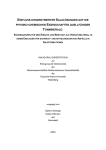
Page 22
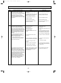
NECESSARY CONDITIONS FOR SYSTEM CONSTRUCTION
8-1. TRANSMISSION SYSTEM SETUP
OC272A--1.qxp
03.9.4 11:06 AM
Page 23
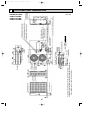
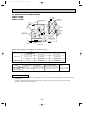
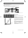
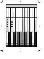
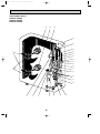
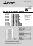
8-2. REFRIGERANT SYSTEM DIAGRAM
PUMY-P125VMA
PUMY-P125YMA
PUMY-P125YMA1
High-pressure sensor
Service port
#50
Strainer
(Refrigerant flow)
Cooling
Heating
discharge pressure sensor
(63HS)
4-way
valve
Oil
separator
Flare
Thermistor TH6
(outdoor air
temperature sensor)
Check valve
(High pressure)
Strainer
(#100)
Check valve
(low pressure)
Strainer
#100
Capillary
tube 1
Thermistor TH2
(Saturation temperature
of suction pressure)
Capillary
tube 2
Thermistor
TH1 (discharge
temperature
sensor)
Outdoor heat exchanger
Strainer
Compressor
(MC)
Accumulator
Expansion valve (LEV(A), SLEV)
Flare
Thermistor TH5
(piping temperature
monitoring and
determination)
Electromagnetic valve
(SV1)
Capillary
tube 4
Dryer
Strainer
#100
Service port
Capillary
tube 3
Thermistor THHS
(Radiator panel
temperature sensor)
W Only PUMY-P125VMA
Thermistor THHS-A
Thermistor THHS-B
Overcooling heat exchanger
Strainer
#100
Outdoor unit
Refrigerant Piping Specifications (dimensions of flared connector)
Item
Liquid piping
Gas piping
20 , 25 , 32 , 40
{6.35 <1/4”>
{12.7 <1/2”>
50 , 63 , 71, 80
{9.52 <3/8”>
{15.88 <5/8”>
100 , 125
{9.52 <3/8”>
{19.05 <3/4”>
125
{9.52 <3/8”>
{19.05 <3/4”>
Capacity
Indoor unit
Outdoor unit
Capillary tube 1
(for return of oil from
oil separator)
PUMY-P125VMA
PUMY-P125YMA
PUMY-P125YMA1
Capillary tube 3
Capillary tube 2
Capillary tube 4
(for maintaining equilibrium
(for Evaporating
(for SV1)
temperature detection) between upper and lower coils)
{2.5 O {0.6 O L500 {2.5 O {0.6 O L500
({4 O {3.0 O L200) O 2
{4 O {2.4 O L360
Concerning the Compressor
This system has a scroll compressor. This compressor uses a low pressure shell that typically has a temperature in the
range 30-80°C.
In addition, compressor wiring should be in the direction of rotation to the right. Wire colors are red (U), white(V),
black (W), yellow and yellow (thermal switch).
23
OC272A--1.qxp
03.9.4 11:06 AM
Page 24
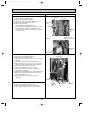
8-3. SYSTEM CONTROL
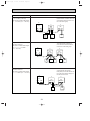
8-3-1. Operating a Single Refrigerant System
When operating either alone or as part of a group, a M-NET remote controller (NR) may be used to control a single
refrigerant system that does not overlap with any other system.
<Example of system arrangement>
Using a M-NET remote controller (NR)
✽ Address setting must be performed.
✽ The NR wire and indoor and outdoor transmission wires must be a non-polar two wire cable.
✽ One NR may be connected to a maximum of 16 indoor unit.
✽ Two NR units may be used to perform control tasks (the second one pressed will have priority if two are pressed
simultaneously).
✽ For the system utilizing R-Converter units (PAC-SF29LB), the following systems are not available. Group operation
system, centralized controller, group remote controller, etc. (See the installation manual of R-Converter units.)
indoor-outdoor trnasmission cable
Outdoor
unit
Indoor unit
Indoor unit
Remote
control wire
Indoor unit
For indoor-outdoor
transmission wire
NR
NR
NR
NR
2 remote controllers
Indoor unit
NR
Indoor unit
Remote controller
network
Group operation (maximum
16 indoor units)
✽ If the user plans to install multiple refrigerant
systems and a centralized controller in the
future, it is strongly suggested that a NR be
used.
24
OC272A--1.qxp
03.9.4 11:06 AM
Page 25
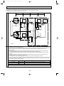
8-3-2. System Controller (SC) to Perform Centralized Control
<Example of System Arrangement>
The following diagram shows the use of system controller (SC) to control a system that includes the multiple outdoor unit.
Indoor • outdoor transmission wire (Shielded wire)
<Room A>
Outdoor
unit
Transmission
wire for centralized control
Indoor unit
<Room B>
Indoor unit
Indoor unit
A
A
<Room C>
Remote control
wire
Indoor unit
Indoor unit
A
Remote controller network
Indoor • outdoor transmission wire (Shielded wire)
<Room D>
Outdoor
unit
Indoor unit
<Room E>
Indoor unit
A
For transmission
wire
Power supply installation
Indoor unit
Indoor unit
A
Indoor unit
A
System controller SC: Centralized controller, linked system control board, group remote controller, etc.
PAC-SC33KUA
PAC-SC34KUA
A : M-NET or MA remote controller
(Coexistence of M-NET remote controller and MA remote controller is not admitted in the same system.)
Note 1) The NR, SC, indoor and outdoor unit all require address settings.
Indoor unit
Outdoor unit
M-NET R/C (Main)
M-NET R/C (Sub)
SC
MA Remote controller
Linked settings must be made within a group.
1 ~ 50
The lowest address of an indoor unit within a refrigerant system is +50.
51 ~ 100 w
The lowest address of an indoor unit within a group is +100.
101 ~ 150
The address of the main remote controller is +50.
151 ~ 200
0 or 201 ~ 250
Unnecessary address setting (Necessary main/sub setting)
—
w The address automatically becomes “100” if it is set as “01~50”. (PUMY-P125VMA)
2) Indoor unit that may be connected with an SC are shown as follows.
Centralized controller
Multi-unit controller board
Group controller
50 group /50 units
24 group /50 units
8 group /16 units
3) There may be a maximum of two controllers when a group has 16 indoor units or less.
4) The transmission wire must have a power supply when an SC is used. Please connect the power supply for
the transmission wire to the centralized controller transmission wire.
SC with 2 units or less
SC with 3 to 5 units
Power supply for transmission wire PAC-SC33KU
Power supply for transmission wire PAC-SC34KU
5) Use a shielded wire (at least 1.25mm2)for the indoor, outdoor, and centralized controller transmission wires.
In addition, all shielded wires in a system must be grounded at one point. If the length of the remote control
wire exceeds 10m, use an insulated wire for the extra portion.
25
OC272A--1.qxp
03.9.4 11:06 AM
Page 26
8-3-3. Example for the System
• Example for wiring control cables, wiring method and address setting, permissible lengths, and the prohibited items are listed
in the standard system with detailed explanation.
The explanation for the system in this section : Use one single outdoor unit and multiple outdoor units for M-NET remote
control system.
Use one single outdoor unit and multiple indoor units in the multiple outdoor
units for the M-NET remote control system.
A. Example of a M-NET remote controller system (address setting is necessary.)
Example of wiring control cables
1. Standard operation
L1
Wiring Method and Address Setting
L2
OC
IC
IC
(051)
TB7
M1 M2S
M1 M2S
(001)
(002)
TB5 TB15
TB5 TB15
M1 M2S
1 2
M1 M2 S
1 2
r1
r2
L3
TB3
Unit
TB6
(102)
TB6
(101)
Outdoor unit
(OC)
NR
NR
IC
IC
(051)
(001)
M1 M2S
M1 M2S
TB6
(101)
• Using two remote controllers
for each indoor unit.
1 2
M1 M2S
TB6
(151)
TB15
TB5
TB6
(102)
Outdoor unit
(OC)
TB6
(152)
NR
NR
NR
NR
Main
Sub
Main
Sub
3. Group operation
Main
OC
Sub
IC
IC
(051)
(001)
TB3
TB7
M1 M2S
M1 M2S
(002)
TB5
TB15
TB5
TB15
M1 M2 S
1 2
M1 M2 S
1 2
TB6
(101)
• Multiple indoor units operated
together by one remote
controller
Indoor Unit (IC)
1 2
M1 M2S
NR
Setting Method
—
Use the most recent
051 to 100 address of all the indoor
units plus 50.
Indoor unit address plus
101 to 150
100.
Indoor unit address plus
151 to 200
150.
Range
001 to 050
Unit
(002)
TB15
101 to 150
Setting Method
—
Use the most recent
address of all the indoor
unit plus 50.
Indoor unit address plus
100.
a. Same as above.
b. Same as above.
c. Set address switch as shown below.
OC
TB5
051 to 100
Remote
controller (NR)
2. Operation using two remote controllers
TB7
Range
001 to 050
Indoor unit (IC)
• One remote controller for each
indoor unit.
• Inside ( ) Address: There is no need
for setting the 100 position on the
remote controller.
TB3
a. Use feed wiring to connect terminals M1 and M2 on
transmission cable block (TB3) for the outdoor unit
(OC) to terminals M1 and M2 on the transmission
cable block (TB5) of each indoor unit (IC). Use
non-polarized two wire.
b. Connect terminals M1 and M2 on transmission
cable terminal block (TB5) for each indoor unit with
the terminal block (TB6) for the remote controller
(NR).
c. Set the address setting switch as shown below.
Main Remote
Controller (NR)
Sub Remote
Controller (NR)
a. Same as above.
b. Connect terminals M1 and M2 on transmission cable
terminal block (TB5) of the IC main unit with the most
most recent address within the same indoor unit (IC)
group to terminal block (TB6) on the remote controller.
c. Set the address setting switch as shown below.
Unit
IC (Main)
Range
001 to 050
IC (Sub)
001 to 050
Outdoor Unit
051 to 100
Main Remote
Controller
Sub Remote
Controller
101 to 150
151 to 200
Setting Method
Use the most recent address within
the same group of indoor units.
Use an address, other than that of
the IC (Main) from among the units
within the same group of indoor
units. This must be in sequence with
the IC (Main).
Use the most recent address of all
the indoor units plus 50.
Set at an IC (Main) address within
the same group plus 100.
Set at an IC (Main) address within
the same group plus 150.
d. Use the indoor unit (IC) within the group with the
most functions as the IC (Main) unit.
Combinations of 1through 3 above are possible.
26
OC272A--1.qxp
03.9.4 11:06 AM
Page 27
• Name, Symbol and the Maximum Remote controller Units for Connection
Name
Outdoor unit
Symbol
Indoor unit
IC
One OC unit can be connect to 1-8 IC units
M-NET remote
controller
NR
Maximum two NR for one indoor unit, Maximum 16 NR for one OC
Maximum units for connection
OC
Permissible Lengths
Longest transmission cable length
(1.25 mm2 )
L1 + L2, L2 + L3, L3 + L1 [ 200m
Remote controller cable length
1. If 0.5 to 0.75 mm2
R1, R2 [10m
2. If the length exceeds 10 meters,
the exceeding section should
be 1.25 mm2 and that section
should be a value within the
total extension length of the
transmission cable and
maximum transmission cable
length. (L3)
Prohibited items
• M-NET remote controller(NR) and MA remote controller(MA) cannot be used together.
• Do not connect anything with TB15 of indoor unit(IC).
OC
IC
IC
(051)
TB3
TB7
M1 M2S
M1 M2S
(001)
(002)
TB5 TB15
TB5 TB15
M1 M2 S
1 2
M1 M2 S
1 2
TB6
(101)
NR
Same as above
MA
OC
IC
IC
(001)
(002)
(051)
TB5 TB15
TB3
TB7
M1 M2S
M1 M2S
M1 M2 S
TB6
(101)
TB5
1 2
M1 M2 S
TB6
(151)
TB6
(102)
TB15
1 2
TB6
(103)
TB6
(104)
NR
NR
NR
NR
NR
Main
Sub
Main
Sub
• Use the indoor unit(IC)
address plus 150 as
the sub remote controller
address. In this case, it
should be 152.
• Three or more remote
controller (NR) cannot
be connected to one
indoor unit.
Same as above
OC
Main
Sub
IC
IC
(001)
TB5 TB15
TB5 TB15
(051)
TB3
TB7
M1 M2S
M1 M2S
M1 M2 S
TB6
(102)
NR
27
1 2
(002)
M1 M2 S
1 2
• The remote controller
address is the indoor
unit main address plus
100. In this case, it
should be 101.
OC272A--1.qxp
03.9.4 11:06 AM
Page 28
B. Example of a group operation system with two or more outdoor units and a M-NET remote controller.
(Shielding wires and address settings are necessary.)
L1
L2
L3
L4
Between
terminal blocks
Group 1
OC
IC
CN40
Group 5
Group 3
IC
IC
IC
Examples of Transmission Cable Wiring
(051)
(001)
TB3
M1 M2 S
(004)
TB5 TB15
M1 M2 S
M1 M2 S
(005)
TB5 TB15
1 2
M1 M2 S
(006)
TB5 TB15
1 2
M1 M2 S
1 2
TB5 TB15
M1 M2 S
1 2
R2
R1
TB7
R3
L9
Shielded wire
TB6
(101)
L5
NR
L6
L7
TB6
(105)
TB6
(155)
NR
NR
Sub remote
controller
OC
IC
IC
IC
(052)
(003)
(002)
TB5
TB3
M1 M2 S
M1 M2 S
M1 M2 S
TB5 TB15
TB15
M1 M2 S
1 2
1 2
(007)
TB5
M1 M2 S
TB15
1 2
R4
L8
TB7
()
TB6
(103)
Address
Wiring Method Address Settings
NR
a. Always use shielded wire when making connections between the outdoor unit (OC) and the indoor unit (IC), as well
for all OC-OC, and IC-IC wiring intervals.
b. Use feed wiring to connect terminals M1 and M2 and the ground terminal on the transmission cable terminal block
(TB3) of each outdoor unit (OC) to terminals M1 and M2 on the terminal S on the transmission cable block of the
indoor unit (IC).
c. Connect terminals M1 and M2 on the transmission cable terminal block of the indoor unit (IC) that has the most
recent address within the same group to the terminal block (TB6) on the remote controller (NR).
d. Connect together terminals M1, M2 and terminal S on the terminal block for central control (TB7) for the outdoor
unit (OC).
e. Use the grounded wire to connect the S-terminal on the transmission terminal of the outdoor unit (OC) and the
grounded terminal for the electrical components box.
f. On one outdoor unit only, change the jumper connector on the control panel from CN41 to CN40.
g. Connect the terminal S on the terminal block for central control (TB7) for the outdoor unit (OC) for the unit into which
the jumper connector was inserted into CN40 in Step above to the ground terminal ; in the electrical component
box.
h. Set the address setting switch as follows.
Setting Method
Unit
Range
Use the most recent address within the same group of indoor units.
IC (Main)
001 to 050
IC (Sub)
001 to 050
Outdoor Unit
Main Remote Controller
Sub Remote Controller
051 to 100
101 to 150
151 to 200
Use an address, other than that of the IC (Main) from among the units within
the same group of indoor units. This must be in sequence with the IC (Main).
Use the most recent address of all the indoor units plus 50.
Set at an IC (Main) address within the same group plus 100.
Set at an IC (Main) address within the same group plus 150.
i. The group setting operations among the multiple indoor units is done by the remote controller (NR) after the electrical
power has been turned on.
28
OC272A--1.qxp
03.9.4 11:06 AM
Page 29
Permissible Length
• Name, Symbol, and the Maximum Units for Connection
• Max length via outdoor units : L1+L2+L3+L4+L5+L6+L7+L9
L1+L2+L3+L4+L5+L6+L8+L9 [ 500 meters (1.25mm2)
• Max transmission cable length : L1+L2+L3+L4, L5+L6+L7, L5+L6+L8, L7+L8 [ 200 meters (1.25mm2)
• Remote controller cable length : R1,R2, R3, R4 [ 10 meters (0.5 to 0.75mm2)
If the length exceeds 10 meters, use a 1.25 mm2 shielded wire. The length of this section (L8) should be included in the calculation of the maximum length and overall length.
Group 1
Group 5
Group 3
OC
IC
IC
CN40
IC
IC
(051)
(001)
TB3
M1 M2 S
TB5 TB15
M1 M2 S
M1 M2 S
1 2
(004)
TB5 TB15
M1 M2 S
1 2
(005)
(006)
TB5 TB15
M1 M2 S
1 2
TB5 TB15
M1 M2 S
1 2
TB7
Prohibited items
Shielded wire
TB6
(101)
TB6
(105)
TB6
(155)
NR
NR
NR
Remote
controller
OC
IC
IC
IC
(052)
(003)
(002)
TB3
M1 M2 S
TB5 TB15
M1 M2 S
M1 M2 S
1 2
TB5 TB15
M1 M2 S
1 2
(007)
TB5 TB15
M1 M2 S
1 2
TB7
TB6
(103)
NR
• The terminal S on the terminal block (TB7) for the central control panel should be connected to the ground terminal ;
of the electric components box for one outdoor unit only.
• Never connect together the terminal blocks (TB5) for transmission wires for indoor units (IC) that have been connected to
different outdoor units (OC).
• Set all addresses to ensure that they are not overlapped.
• It cannot be connected M-NET remote controller and MA remote controller with indoor unit of the same group using
together.
29
OC272A--1.qxp
03.9.4 11:06 AM
Page 30
C. Example of a MA remote controller system (address setting is not necessary.)
NOTE : In the case of same group operation, need to set the address that is only main indoor unit.
Example of wiring control cables
1. Standard operation
L1
Wiring Method and Address Setting
L2
OC
IC
IC
(000)
M1 M2S
M1 M2S
(000)
(000)
TB5 TB15
TB5 TB15
M1 M2S 1 2
M1 M2 S 1 2
r2
TB7
r1
TB3
• One remote controller for each
indoor unit.
• Inside ( ) Address: There is no need
for setting the 100 position on the
remote controller.
MA
MA
2. Operation using two remote controllers
OC
IC
IC
(000)
(000)
TB3
TB7
M1 M2S
M1 M2S
(000)
TB5 TB15
TB5 TB15
M1 M2 S 1 2
M1 M2S 1 2
r3
r5
6
r
4
r
• Using two remote controllers
for each indoor unit.
MA
MA
MA
OC
IC
IC
(000)
(000)
(000)
TB5 TB15
M1 M2 S 1 2
TB5
TB15
M1 M2 S 1 2
r7
TB7
M1 M2S
• Multiple indoor units operated
together by one remote
controller
a. The same as above.
b. The same as above.
c. In the case of using tow remote controllers, connect
terminals 1 and 2 on transmission cable terminal
block (TB15) for each indoor unit with the terminal
block for tow remote controllers.
· Set the sub remote controller position for one of
MA remote controller’s main switch.
Refer to the installation manual of MA remote
controller
MA
3. Group operation
TB3
M1 M2S
a. Use feed wiring to connect terminals M1 and M2 on
transmission cable block (TB3) for the outdoor unit
(OC) to terminals M1 and M2 on the transmission
cable block (TB5) of each indoor unit (IC). Use
non-polarized two wire.
b. Connect terminals 1 and 2 on transmission cable
terminal block (TB15) for each indoor unit with the
terminal block for the MA remote controller (MA).
MA
r7
Combinations of 1through 3 above are possible.
30
a. The same as above.
b. The same as above.
c. Connect terminals 1 and 2 on transmission cable terminal block (TB15) of each indoor unit, which is doing
group operation with the terminal block the MA remote
controller. Use non-polarized tow wire.
d. In the case of same group operation, need to set the
address that is only main indoor unit. Please set the
address of the indoor unit with the most functions in
the same group in the number that 01-50 is young.
OC272A--2.qxp
03.9.4 11:08 AM
Page 31
Permissible Lengths
Prohibited items
The MA remote controller and the
M-NET remote controller cannot be
used together with the indoor unit
the of the same group.
Longest transmission cable length
L1 + L2 [ 200m (1.25 mm2)
MA remote controller cable length
R1, R2 [ 200m (0.3 ~ 1.25 mm2)
OC
IC
IC
(000)
TB3
TB7
M1 M2S
M1 M2S
(000)
(000)
TB5 TB15
TB5 TB15
M1 M2 S
1 2
NR
Longest transmission cable length
The same as above.
MA remote controller cable length
R3 +R4, R5 +R6 [ 200m
(0.3 ~ 1.25 mm2)
M1 M2 S
1 2
MA
MA
Three MA remote controller or
more cannot be connect with the
indoor unit of the same group.
OC
IC
IC
(000)
TB3
TB7
M1 M2S
M1 M2S
(000)
(000)
TB5 TB15
TB5 TB15
M1 M2 S
MA
1 2
M1 M2 S
MA
MA
Longest transmission cable length
The same as above.
MA remote controller cable length
R7 +R8 [ 200m (0.3 ~ 1.25 mm2)
1 2
MA
MA
The second MA remote control is
connected with the terminal
block(TB15) for the MA remote control of the same indoor unit(IC) as
the first remote control.
OC
IC
IC
(051)
TB3
TB7
M1 M2S
M1 M2S
(001)
(002)
TB5 TB15
TB5 TB15
M1 M2 S
1 2
MA
31
M1 M2 S
1 2
MA
OC272A--2.qxp
03.9.4 11:08 AM
Page 32
D. Example of a group operation with two or more outdoor units and a MA remote controller.
(Shielding wires and address settings are necessary.)
L1
L2
L3
L4
Between
terminal blocks
Group 1
OC
IC
CN40 CN41
Group 5
Group 3
IC
IC
IC
TB3
M1 M2 S
(001)
(004)
(005)
(006)
TB5 TB15
TB5 TB15
TB5 TB15
TB5 TB15
M1 M2 S 1 2
M1 M2 S
M1 M2 S 1 2
M1 M2 S 1 2
M1 M2 S 1 2
R2
R1
TB7
R3
Shielded wire
L9
Examples of Transmission Cable Wiring
(051)
MA
L5
MA
L6
L7
MA
Sub remote
controller
OC
IC
CN41
IC
IC
(052)
TB3
M1 M2 S
M1 M2 S
(002)
(003)
(007)
TB5 TB15
TB5 TB15
TB5 TB15
M1 M2 S 1 2
M1 M2 S 1 2
M1 M2 S 1 2
R4
L8
TB7
Wiring Method Address Settings
()
Address
MA
a. Always use shielded wire when making connections between the outdoor unit (OC) and the indoor unit (IC), as well
for all OC-OC, and IC-IC wiring intervals.
b. Use feed wiring to connect terminals M1, M2 and S and the ground terminal on the transmission cable terminal block
(TB3) of each outdoor unit (OC) to terminals M1, M2 and S on the transmission cable block (TB15) of the
indoor unit (IC).
c. Connect terminals M1 and M2 on the transmission cable terminal block of the indoor unit (IC) that has the most
recent address within the same group to the terminal block on the remote controller (MA).
d. Connect together terminals M1, M2 and terminal S on the terminal block for central control (TB7) for the outdoor
unit (OC).
e. Use the grounded wire to connect the S-terminal on the transmission terminal of the outdoor unit (OC) and the
grounded terminal for the electrical components box.
f. On one outdoor unit only, change the jumper connector on the control panel from CN41 to CN40.
g. Connect the terminal S on the terminal block for central control (TB7) for the outdoor unit (OC) for the unit into which
the jumper connector was inserted into CN40 in Step above to the ground terminal ; in the electrical component box.
h. Set the address setting switch as follows.
Unit
IC (Main)
Range
001 to 050
IC (Sub)
001 to 050
Outdoor Unit
051 to 100
Setting Method
Use the most recent address within the same group of indoor units.
Use an address, other than that of the IC (Main) from among the units within
the same group of indoor units. This must be in sequence with the IC (Main).
Use the most recent address of all the indoor units plus 50.
32
OC272A--2.qxp
03.9.4 11:08 AM
Page 33
Permissible Length
• Name, Symbol, and the Maximum Units for Connection
• Max length via outdoor units : L1+L2+L3+L4+L5+L6+L7+L9
L1+L2+L3+L4+L5+L6+L8+L9 [ 500 meters (1.25mm2)
• Max transmission cable length : L1+L2+L3+L4, L5+L6+L7, L5+L6+L8, L7+L8 [ 200 meters (1.25mm2)
• Remote controller cable length : R1,R2, R3, R4 [ 10 meters (0.5 to 0.75mm2)
If the length exceeds 10 meters, use a 1.25 mm2 shielded wire. The length of this section (L8) should be included in the calculation of the maximum length and overall length.
Group 1
Group 3
IC
IC
Group 5
OC
CN40
IC
IC
(051)
TB3
M1 M2 S
M1 M2 S
(001)
(004)
(005)
(006)
TB5 TB15
TB5 TB15
TB5 TB15
TB5 TB15
M1 M2 S 1 2
M1 M2 S 1 2
M1 M2 S 1 2
M1 M2 S 1 2
TB7
Shielded wire
MA
Prohibited items
MA
MA
OC
IC
IC
(002)
TB5 TB15
(003)
(007)
TB5 TB15
TB5 TB15
IC
(052)
TB3
M1 M2 S
M1 M2 S
M1 M2 S 1 2
M1 M2 S 1 2
M1 M2 S 1 2
TB7
MA
• The terminal S on the terminal block (TB7) for the central control panel should be connected to the ground terminal ;
of the electric components box for one outdoor unit only.
• Never connect together the terminal blocks (TB5) for transmission wires for indoor units (IC) that have been connected to
different outdoor units (OC).
• M-NET remote controller and MA remote controller cannot be connected with the indoor unit of the same group wring
together
33
OC272A--2.qxp
9
03.9.4 11:08 AM
Page 34
TROUBLESHOOTING
9-1. CHECK POINTS FOR TEST RUN
9-1-1. Procedures of test run
(1) Before test run, make sure that following work is completed.
• Installation related :
Make sure that the panel of cassette type and electrical wiring is done.
Otherwise electrical functions like auto vane will not operate normally.
• Piping related :
Perform leakage test of refrigerant and drain piping.
Make sure that all joints are perfectly insulated.
Check stop valves on both liquid and gas side for full open.
• Electrical wiring related :
Check ground wire, transmission cable, remote controller cable, and power supply cable for secure connection.
Make sure that all switch settings of address or adjustments for special specification systems are correctly settled.
(2) Safety check :
With the insulation tester of 500V, inspect the insulation resistance.
Do not touch the transmission cable and remote controller cable with the tester.
The resistance should be over 1.0 MΩ. Do not proceed inspection if the resistance in under 1.0 MΩ.
Inspect between the outdoor unit power supply terminal block and ground first, metallic parts like refrigerant pipes or the electrical box next,
then inspect all electrical wiring of outdoor unit, indoor unit, and all linked equipment .
(3) Before operation :
a) Turn the power supply switch of the outdoor unit to on for compressor protection. For a test run, wait at least 12 hours from this point.
b) Register control systems into remote controller(s). Never touch the on/ off switch of the remote controller(s). Refer to “ 8-1-2 M-NET
Remote Controller Settings” on page 29 as for settings . In MA remote controller(s), this registration is unnecessary.
(4) More than 12 hours later form power supply to the outdoor unit, turn all power switch to on for test run. Perform test run according to the
“Operation procedure” table of the bottom of this page. While test running, make test run reports .
(5) When you deliver the unit after test run, instruct the end user for proper usage of the system using owners’ manual and the test run report
you made to certificate normal operation. If abnormalities are detected during test run, refer to “ 8-1-3 Countermeasures for Error During
Test Run” on page 31. As for DIP switch setting of outdoor unit, refer to” 8-5. INTERNAL SWITCH FUNCTION TABLE” on page 54.
Check code indicator (see NOTE 1)
Test run remaining time indicator (see NOTE 3)
Indoor unit liquid pipe temperature indicator
(see NOTE 4)
TEST RUN indicator
1Hr.
˚C
Display panel
TEST RUN
TEMP.
(Cooling/Heating)
OPERATION
SWITCH button
3,4
ON/OFF LED (Lights up in operation)
ON/OFF button 9
ON/OFF
FILTER
AIR DIRECTION button 2
CHECK TEST
PAR-20MAA
TEST RUN button 2
TIMER SET
LOUVER button 6
Control panel
AIR SPEED button 5
Operation procedure
1 Turn on the main power supply the all units at least 12 hrs. before test run. ”HO” appears on display panel for 3 min.
2 12 hrs later, press TEST RUN button twice to perform test run. “TEST RUN “ appears on display panel.
3 Press OPERATION SWITCH button to make sure that air blows out.
4 Select Cooling (or Heating) by OPERATION SWITCH button to make sure that cool (or warm) air blow out.
5 Press Fan speed button to make sure that fan speed in changed by the button.
6 Press AIR DIRECTION button or LOUVER button to make sure that air direction is adjustable(horizontal, downward, upward, and each angle).
7 Check outdoor fans for normal operation.
8 Check interlocked devices (like ventilator) for normal operation, if any. This is the end of test run operation.
9 Press ON/OFF button to stop and cancel test run.
NOTE 1 : If error code appears on remote controller or remote controller malfunction , refer to “ 8-1-3 Countermeasures for Error During Run”
on page 31.
NOTE 2 : During test run operation 2-hours off timer activates automatically and remaining time is on remote controller and test run stops 2 later.
NOTE 3 : During test run, the indoor liquid pipe temperature is displayed on remote controller instead of room temperature.
NOTE 4 : Depend on a model, “This function is not available” is appears when air direction button is pressed, however, this is not malfunction.
34
OC272A--2.qxp
03.9.4 11:08 AM
Page 35
9-1-2. Special Function Operation and Settings (for M-NET Remote Controller)
• It is necessary to perform “group settings” and “paired settings” at making group settings of different refrigerant
systems (multiple outdoor unit).
(A) Group settings: Enter the indoor unit controlled by the remote controller, check the content of entries, and clear
entries, etc.
(B) Paired settings: Used to set the linked operation of a Lossnay unit.
(1) Entering address: Follow the steps below to enter the addresses of the indoor unit using the remote controller.
a) Group settings
• Turning off the remote controller: Press the ON/OFF button to stop operation (the indicator light will go off).
• Changing to indoor unit address display mode: If the FILTER and k buttons on the remote controller are
pressed simultaneously and held for two seconds, the display shown in Figure 1 will appear.
• Changing address: Press the temperature adjustment
buttons to change the displayed address to the
address to be entered.
• Entering the displayed address: Press the TEST RUN button to enter the indoor unit with the displayed address.
The type of the unit will be displayed as shown in Figure 2 if entry is completed normally.
If a selected indoor unit does not exist, an error signal will be displayed as shown in Figure 3. When this happens,
check whether the indoor unit actually exists and perform entry again.
• Returning to the normal mode after completing entry: Press the FILTER and k buttons simultaneously and
hold for two seconds to return to the normal mode.
Figure 1 (A) Group setting display
Figure 2 Normal completion of entry
Type of unit is displayed
Figure 3 Entry error signal
Flashing “88” indicates entry error
b) Paired Settings
• Turn off the remote controller: Press the remote controller’s ON/OFF button to turn it off (the indicator light will go off).
• Put in indoor unit address display mode: Press the FILTER and k buttons on the remote controller simultaneously
and hold for two seconds.
✻The above steps are the same as when making group settings (A).
• Changing to the linked operation unit address display state: The display shown in Figure 4 will appear when the a
button on the remote control is pressed.
• Displaying the address of the Lossnay unit and linked indoor unit: In this situation, the indoor unit
number will be the lowest address of the group. The Lossnay unit will not operate if this setting is
incorrect.
✻If the temperature adjustment
buttons are pressed, the address may be changed to the indoor unit that are
to be linked.
✻If the time setting
buttons are pressed, the address of the linked units may be changed to the address where
it is desired to enter the Lossnay .
• Linking the Lossnay and the indoor unit: The display shown in Figure 5 will appear when the TEST RUN
button is pressed. The indoor unit whose address is displayed and the Lossnay unit with a linked address
will operate in a linked manner.
✻If it is desired to display the address of the Lossnay in the indoor unit address, display the indoor
unit address in the linked unit address, and the above content will also be recorded.
✻ Apart from the indoor unit with the lowest address in the group, display and enter the addresses of the other indoor unit
that are to be linked with the Lossnay unit.
• Returning to the normal mode after completing entry: Press the FILTER and k buttons on the remote controller
simultaneously and hold for two seconds to return to the normal mode.
Figure 4 (B) Making paired settings
The addresses of indoor
unit and linked units are
displayed simultaneously.
Figure 5 Completing normal entry
(alternating
display)
35
These alternating IC or LC displays will appear
when entry is completed normally.
A flashing “88” will appear if there is a
problem with the entry (indicating that the
unit does not exist).
OC272A--2.qxp
03.9.4 11:08 AM
Page 36
(2) Address check: Refer to section (1) regarding address entry.
a) In making group settings:
• Turn off the remote controller: Press the remote controller's ON/OFF button to stop operation (the indicator light will go off).
• Locate the indoor unit address display mode: Press the FILTER and k buttons on the remote controller simultaneously
and hold for two seconds.
• Display indoor unit address: The entered indoor units address and type will be displayed each time the button is pressed.
✻ When one entry is made, only one address will be displayed no matter how many times the w button is pressed.
• Returning to the normal mode after completing check: Simultaneously press the FILTER and k buttons on the remote
controller and hold for two seconds to return to the normal mode.
b) In making paired settings:
• Turn off the remote controller: Press the remote controller's ON/OFF button to stop operation (the indicator light will go off).
• Put in indoor unit address display mode: Press the FILTER and k buttons on the remote controller simultaneously and
hold for two seconds.
• Changing to the linked operation unit address display state: Press the a button on the remote control.
• Displaying the address of the indoor unit to be checked: Change the address to that of the indoor unit to be checked by pressing the temperature adjustment buttons
.
• Displaying the address of the linked Lossnay unit: Press the w button to display the addresses of the linked Lossnay and
indoor unit in alternation.
• Displaying the addresses of other entered units: The addresses of the other entered units will be displayed in alternating fashion after resting the w button again.
• Returning to the normal mode after completing the check: Simultaneously press the FILTER and k buttons on the remote
controller and hold for two seconds to return to the normal mode.
(3) Clearing an address: Refer to section (1) regarding the address entry and section (2) regarding checking addresses.
a) In making group settings:
• Turn off the remote controller: The procedure is same as a) in (2) Address check.
• Put in the indoor unit address display mode: The procedure is same as a) in (2) Address check.
• Displaying the indoor unit address to be cleared: The procedure is same as a) in (2) Address check.
• Clearing indoor unit address : ......Pressing the q button on the remote controller twice will clear the address entry of the
displayed indoor unit, resulting in the display shown in Figure 6.
The display shown in Figure 7 will appear if an abnormality occurs and the entry is not cleared.
Please repeat the clearing procedure.
• Returning to the normal mode after clearing an address: The procedure is same as a) in (2) Address check.
Figure 7 Display when an abnormality
Figure 6 Display after address has been
has occurred during clearing
cleared normally
"--" will appear in the room temperature
display location.
"88" will appear in the room temperature display location.
b) In making paired settings:
• Turn off the remote controller: The procedure is same as b) in (2) Address check.
• Put into the indoor unit address display mode: The procedure is same as b) in (2) Address check.
• Put into the linked unit address display mode: The procedure is same as b) in (2) Address check.
• Display the address of the Lossnay unit or the indoor unit to be cleared.
• Deleting the address of a linked indoor unit: Pressing the q button on the remote controller twice will clear the address
entry of the displayed indoor unit, resulting in the display shown in Figure 8.
• Returning to the normal mode after clearing an address: The procedure is same as b) in (2) Address check.
Figure 8 Display after address has been cleared normally
(altenating
display)
"--" will appear in the unit type display location when an address has
been cleared normally.
"88" will appear in the unit type display location when an abnormality
has occurred during clearing.
36
OC272A--2.qxp
03.9.4 11:08 AM
Page 37
9-1-3. Countermeasures for Error During Test Run
• If a problems occurs during test run, a code number will appear in the temperature display area on the remote controller
(or LD1 on the outdoor unit), and the air conditioning system will automatically cease operating.
Determine the nature of the abnormality and apply corrective measures.
Check code
1102
1108
1302
1500
1501
1505
2502
2503
4115
4116
4220
4230
4250
Trouble
Discharge temperature trouble
Compressor's inner thermal sensor trouble
High pressure trouble
Excessive refrigerant replenishment
Insufficient refrigerant
Vacuum operation protection
Drain pump trouble
Drain sensor trouble (THd)
Power synchronization signal trouble
Indoor unit fan rotation trouble
Inverter main voltage drop
Overheat protection of radiator panel
Multiple IPM errors (Over current trouble)
Check code
Trouble
6600
Duplicated unit address setting
5101
Intake thermistor trouble (TH21) or discharge
thermistor trouble (TH1)
5102
Liquid pipe thermistor trouble (TH22) or low pressure
saturation thermistor trouble (TH2)
5103
5105
5106
5110
5201
5300
Gas pipe temperature sensor trouble (TH23)
Piping temperature sensor trouble (TH5)
Outdoor temperature sensor trouble (TH6)
ACTM/IGBT Radiator panel thermistor trouble (THHS-A/B)
(PUMY-P125VMA)
IPM Radiator panel thermistor trouble (THHS)
(PUMY-P125YMA, PUMY-P125YMA1)
Pressure sensor trouble (63HS)
Current sensor error (PUMY-P125VMA)
6602
Transmission error (Transmission processor
hardware error)
6603
Transmission error (Transmission route BUSY)
6606
Transmission and reception error
(Communication trouble with transmission processor)
6607
6608
Transmission and reception error (No ACK error)
No response
6831
MA communication receive signal error
(no receive signal)
6832
MA communication send signal error
(starting bit detection error)
6833
MA communication send error (H/W error)
6834
MA communication receive error
(Synchronous recovery error)
7100
7101
7102
7105
7111
0403
Total capacity error
Capacity code error
Connecting unit number error
Address set error
Remote controller sensor trouble
Communication trouble with Power Board (PUMY-P125VMA)
The operational status of the outdoor unit controller is displayed on the LD1 of the outdoor unit under normal conditions (when
all SW1’s are OFF)
1
Compressor
Display item
is operating
Field
2
3
4
52C
21S4
SV1
5
6
7
Example: When the air conditioner is in the heating mode and the SV1 and compressor turned on.
1 2
3 4
5 6
7 8
LD1
52C : Compressor Contactor
21S4 : Four-way valve
SV1 : Bypass valve
37
8
Lit steadily
OC272A--2.qxp
03.9.4 11:08 AM
Page 38
Display
Meaning and detecting method
1102
Discharge temperature abnormality
1 When the discharge temperature thermistor
(TH1) detects 125;or more (1st detection),
the compressor stops and restarts operation
in 3 minutes.
3) Indoor linear expansion valve
operation defective
again (2nd detection) within 30 minutes
since the compressor has stopped, the
compressor stops and restarts operation in 3
minutes.
3 When the thermistor detects 125;or more
again (3rd detection) within 30 minutes since
the compressor has stopped 2 times, the
compressor stops abnormally. <1102> is
displayed.
4) Ball valve operation defective
Check ball valve is fully opened.
5) Outdoor fan block and defective of
fan motor (heating mode)
Check the outdoor fan motor.
6) Gas leakage between high and low
pressure (Defective of 4-way valve or
compressor)
Check the operating condition.
4 When the thermistor detects 125; or
7) Solenoid valve (SV1) performance
defective (control failure to prevent the
discharge temp. from rising by SV1)
Check the solenoid valve performance.
8) Thermistor defective
Check the thermistor resistance.
9) Input circuit defective of multi
controller board
Check the intake temperature in
discharge temperature thermistor (TH1)
by LD1. (See 5101 Discharge
temperature thermistor error)
1) Low voltage supplied to power supply
terminal block
Measure the terminal voltage.
Check the voltage reduction.
2) Power supply L2 or L3 phase is
opened. (When L1 phase is opened,
power supply of the micro computer is
not supplied.)
Check the open phase.
3) Compressor failure (Over current by
motor rare short, etc.)
Check the coil resistance.
4) Overloaded operation
Check the indoor/outdoor unit operating
condition and status.
5) Gas leakage, Gas shortage
Check the refrigerant amount.
6) Inner thermo defective
Check the current flows in inner thermo.
7) Input circuit defective of multi
controller board or power supply board
When the inner thermo is normal and
input circuit is defective, even if the
inner thermo performs, the compressor
does not operate and becomes error in
30 minutes.
1) Indoor unit short cycle
Check the indoor unit.
2) Indoor unit filter clogging
Check the indoor unit filter.
3) Air flow capacity decrease due to
indoor fan dirt
Check the indoor fan.
4) Indoor heat exchanger dirt
Check the indoor unit heat exchanger.
more after 30 minutes since the
compressor has stopped (1st or 2nd time),
it becomes the 1st detection or the same
performance as above-mentioned 1.
5 It is being delay for abnormal stop during 30
minutes since the compressor has stopped.
In this time, check delay code <1202> will
be displayed.
2) Overloaded operation
Compressor inner thermo abnormality
1 When the inner thermo performs (1st
detection) during the compressor operation,
the compressor stops and restarts operation
in 3 minutes.
2 When the inner thermo performs again (2nd
detection) within 30 minutes since the
compressor has stopped, or does not
recover within 30 minutes, it stops
abnormally. In this time <1108> is displayed.
3 When the inner thermo performs after 30
minutes since the compressor has stopped
(1st stop), it is the 1st detection and
becomes the same performance as abovementioned 1.
4 It is being delay for abnormal stop during
30 minutes since the compressor has
stopped. In this time, check delay code
<1208> will be displayed.
1302
1) Gas leakage, Gas shortage
Check points
Check the refrigerant amount.
Check the indoor/outdoor unit operating
condition and status.
Perform cool or heat operation to check
the condition.
2 When the thermistor detects 125;or more
1108
Causes
High-pressure pressure abnormality
1 When high-pressure pressure sensor
detects 2.94MPa or more (1st detection)
during the compressor operation, the
compressor stops and restarts operation in
3 minutes
38
OC272A--2.qxp
03.9.4 11:08 AM
Page 39
Display
Meaning and detecting method
1302 2 When the sensor detects 2.94MPa or more
again (2nd detection) within 30 minutes
since the compressor has stopped, the
compressor stops again and restarts
operation in 3 minutes.
3 When the sensor detects 2.94MPa or more
again (3rd detection) within 30 minutes
since the compressor has stopped, the
compressor stops again and restarts
operation in 3 minutes.
Causes
5) Indoor fan motor lock
Check points
Check the indoor fan motor.
6) Indoor fan motor failure
Check the indoor fan motor.
7) 4-way valve performance failure
(Stop in the middle of performance)
Change COOL/HEAT operation mode
to perform the 4-way valve. If any
defective, replace the 4-way valve.
8) Ball valve performance failure (not
full-opened)
Check the ball valve full-opened.
9) Pipe clogged or broken
Repair the defective points.
10) Indoor linear expansion valve
performance failure
Operate COOL or HEAT operation,
and check the operation condition.
11) Outdoor fan motor lock
Check the outdoor unit fan motor.
12) Outdoor fan motor failure
Check the outdoor unit fan motor.
4 When the sensor detects 2.94MPa or more
again (4th detection) within 30 minutes
after 3rd compressor stop, it stops
abnormally. In this time <1302> is displayed.
5 When the sensor detects 2.94MPa or more
after 30 minutes since the compressor has
stopped (1st or 2nd or 3rd time), it
becomes the 1st detection or the same
performance as above-mentioned 1.
6 It is being delay for abnormal stop during
30 minutes since the compressor has
stopped. In this time, check delay code
<1402> will be displayed.
Note) For first 7 minutes in COOL or HEAT
starting, error detected pressure of highpressure pressure sensor is 3.14MPa.
1500
Refrigerant over charged abnormality
1When below 5 conditions are satisfied
during the compressor operation (1st
detection), the compressor stops and
restarts operation in 3 minutes.
1. Cool mode, outer temp. is 20; or more
Heat mode, outer temp. is 15; or less
13) Outdoor unit short cycle
Check the outdoor unit.
14) Outdoor heat exchanger dirt
Check the outdoor unit heat
exchanger.
15) Decrease in airflow capacity which
the outdoor unit intakes because of
intake defective of outer temperature
thermistor. (Intake less than the actual
outer air)
Check intake temperature of the outer
temperature thermistor by LD1.
(See 5106 Outer temperature
thermistor error)
16) Indoor unit capacity codes miss
setting (If the capacity code is set
greatly, initial frequency rises and highpressure is easy to rise.)
Check the capacity set switch in the
indoor controller board. If it is wrong
setting reset it. Check is available for
the outdoor unit.
(See 7101 Capacity code error)
17) Solenoid valve (SV1) performance
failure (High-pressure pressure cannot
be controlled by SV1)
Check the solenoid valve
performance.
18) Indoor thermistor (liquid pipe
temperature detection) detecting failure
(thermistor removed) (Hot adjust time
becomes long.)
Check the thermistor installed
condition. Operate in trial mode and
check the pipe temperature change
by the remote controller.
19) High-pressure pressure sensor
defective
Check the high-pressure pressure
sensor.
20) High-pressure pressure sensor
input circuit defective in multi controller
board.
Check the high-pressure pressure
sensor.
1) Refrigerant over charged
Check the refrigerant amount.
2) Light-loaded operation (Wrong
determination)
Check the indoor/outdoor unit
operating condition and status.
3) Performance defective of the
indoor's linear expansion valve and
outdoor's electronic expansion valve.
Perform cool or heat operation to
check the condition.
39
OC272A--2.qxp
03.9.4 11:08 AM
Page 40
Display
Meaning and detecting method
1500
2. The compressor has operated
consecutively 20 minutes or more, since
the indoor unit operation capacity had
changed (including the compressor
operation start).
4) Discharge super heat detection error
3. Operation frequency is 80Hz or more.
failure
Check points
Causes
1 High-pressure pressure sensor
failure
1 Check the high-pressure pressure
sensor.
2 Discharge temperature thermistor
2 Check the resistance of discharge
temp. thermistor.
1 234 567 8
4. Discharge super heat is below 10;.
3 Thermistor input circuit defective in
5. Sub cool step continues for 5 minutes
or more by SN=4.
the multi controller board., and highpressure pressure sensor input circuit
failure
2 Same condition as 1 is satisfied again
3. Discharge super heat is 60; or more.
4. Difference of outer temperature thermistor
(TH6) and outdoor piping temp. thermistor
(TH5) applies to the formula of (TH6-TH5)<5;.
1) Gas leakage, Gas shortage
Check the refrigerant amount.
2) When heating operation, refrigerant
shortage feeling operation
(When heating, air flow or thermo OFF
are mixed-operation, it cause a
refrigerant shortage operation.)
3) Ball valve performance failure (not
full opened.)
Check the operation condition and
refrigerant amount.
1 High-pressure pressure sensor
defective
1 Check the high-pressure pressure
sensor.
2 Discharge temperature thermistor
2 Check the resistance of discharge
temperature thermistor.
3 Thermistor input circuit defective and 3 Set the SW1 to
high-pressure pressure sensor
defective in multi controller board
1 234 567 8
on
and
check the high-pressure pressure
sensor level.
1 234 567 8
Set the SW1 to on
and
check the discharge temp. thermistor
level.
1. Compressor is operating.
2. When cooling, discharge super heat is
70; or more.
When the high-pressure pressure
sensor and discharge temp. thermistor
are normal, if the above mentioned
detecting pressure level and temp. are
big different from the actual pressure
and temp. replace the multi controller
board.
When heating, discharge super heat is 95;
or more.
2 When the conditions of detecting mode
1and 2are satisfied again (2nd detection)
within 30 minutes since the compressor has
stopped, it stops abnormally. In this time,
<1501> is displayed.
3 When the conditions of detecting mode
1and 2are satisfied again after 30 minutes
since the compressor has stopped (1st
time), it becomes the 1st detection and
same performance as above 1.
4 It is being delay for abnormal stop during 30
minutes since the compressor has stopped.
In this time, check delay code <1600> will
be displayed.
Check the ball valve is full opened.
4) Error detection of discharge super
heat
defective
5. High-pressure pressure sensor is below
1.08MPa.
<Detecting mode 2>
When the below conditions are satisfied
completely.
1 234 567 8
When the high-pressure pressure
sensor and discharge temp. thermistor
are normal, if the above mentioned
detecting pressure level and temp. are
big different from the actual pressure
and temp., replace the multi controller
board.
3 Same condition as 1 is satisfied again
1. SW5-5 is OFF.
2. Compressor is operating in HEAT mode.
and
check the high-pressure pressure
sensor level.
Set the SW1 to on
and
check the discharge temp. thermistor
level.
within 60 minutes since the compressor
has stopped, it stops abnormally. In this
time, <1500> is displayed.
after 60 minutes since the compressor has
stopped (1st time), it becomes the first
detection and same performance as 1.
4 It is being delay for abnormal stop during
60 minutes since the compressor has
stopped. In this time, check delay code
<1600> will be displayed.
Refrigerant shortage abnormality
1501
1 When the conditions of below detecting
mode 1 or 2 are satisfied (1st detection)
during the compressor operation, the
compressor stops and restarts operation in
3 minutes.
<Detecting mode 1>
When the below conditions are satisfied
completely.
3 Set the SW1 to on
5) Error detection of TH5/TH6
1 Thermistor defective
1 Check the resistance of thermistor.
1 234 567 8
2 Thermistor input circuit defective in
multi controller board
40
2 Set the SW1 to
on
and
check the outdoor pipe temp.
thermistor level. 1 2 3 4 5 6 7 8
3 Set the SW1 to on
and
check the outer temp.
thermistor level.
OC272A--2.qxp
03.9.4 11:08 AM
Page 41
Display
Meaning and detecting method
1505
Vacuum operation protection
When the suction pressure saturation
temperature thermistor (TH2) detects -13;
or less and ''[indoor temperature-liquid pipe
temperature][ 8deg'' for 3minutes
continuously, the 1st COOL operation
(compressor operation) after power supply
on, it stops abnormally. In this time, <1505>
is displayed
2502
Drain pump abnormality
1 When either of the undermentioned
condition is satisfied (when determined
drain sensor goes under water) while the
indoor unit operation (excluding the case of
abnormal stop) and after 3minutes since the
drain pump has operated, the indoor unit
stops abnormally (however fan continues
the normal control). In this time, <2502> is
displayed.
· Turn on the side heater of drain sensor,
then when temperature up from the
detected temperature before turning on is
below 20; during 40 seconds.
· The detected temperature is below 63;
after 40seconds since the side heater of
drain sensor has turned on.
Causes
1) Ball valve performance failure (not
full opened.)
Check the ball valve is full opened.
2) Light-loaded operation (When outer
temperature is low, the operation is
liable to change to this mode.)
Check the indoor/outdoor unit
operating condition and status.
3) Low-pressure over suction by
refrigerant shortage
Check the refrigerant amount.
4) Pipe clogging and broken
Repair the defective points.
5) Indoor linear expansion valve
performance defective
Perform cool or heat operation to
check the condition.
1) Drain pump trouble
Check the drain pump.
Performance
2) Drain defective
· Drain pump clogging
· Drain pipe clogging
Please confirm whether water can be
drained.
3) Open circuit of drain sensor side
heater
Confirm the resistance of the drain
sensor side heater. (approx. 82'at
normal between connector CN50 1
and 3 in the indoor controller board)
4) Contact failure of drain sensor
connector
Check the connector contact failure.
1 Check the drain sensor lead- wire
5) Dew condensation on drain sensor
mounted.
· Drain water descends along lead wire.
2 Check the filter clogging
· Drain water waving due to filter
clogging.
6) Indoor controller board defective
· Drain pump drive circuit failure
· Drain heater output circuit failure
2 When condition which the outdoor unit is
stopped forcibly consists, or the drain
sensor detects continuously to go under
water 5 times, and also detects ''[liquid pipe
temperature-suction temperature][ -10deg''
for 30minutes continuously, the indoor unit
stops abnormally (however, fan operates by
normal control) that indoor unit and
excluding [Fan mode or OFF] in same
refrigerant system. Also, the outdoor unit
which is connected to that indoor unit with
refrigerant system stops abnormality
(compressor is inhibited to operation). In
this time, <2502> is displayed.
Check points
7) Both of above mentioned 1)~6) and
the indoor linear expansion valve fullclosed failure (leakage) happens
synchronistically.
41
If the above mentioned checkpoints
has any problem, replace the indoor
controller board.
Check whether the indoor linear
expansion valve leaks or not.
OC272A--2.qxp
Display
2502
03.9.4 11:08 AM
Page 42
Meaning and detecting method
Causes
Check points
Drain pump abnormality
(Note) Address/Attribute displayed on the
remote controller shows the indoor unit
which is cause of trouble.
<Detected timing>
Always detecting regardless of the indoor
unit status.
<Abnormality clear>
Abnormality is cleared by either of two of the
following;
· Reset power supply of the indoor unit and
outdoor unit in same refrigerant system,
which is the cause of trouble in the
refrigerant system.
· Reset power supply of the indoor unit,
which is the cause of trouble. (However,
power supply interception of 10 minutes or
more is necessary.)
(Note) Above 1 and 2 detects independently.
2503
Drain sensor (THd, DS) abnormality
When the drain sensor detects short/open
while the operation.
1) Connector (CN50) contact failure
(insertion failure)
1 Check whether the indoor controller
board connector (CN50) is
disconnected or not.
2) Thermistor wiring disconnection or
half disconnection
2 Check whether the thermistor wiring is
disconnected or not.
Short: detection of 90; or more
Open: detection of -40; or less
3) Thermistor defective
3 Check the resistance of thermistor.
0;···15k'
10;···9.6 k'
20;···6.3 k'
30;···4.3 k'
40;···3.0 k'
4) Indoor controller board (detecting
circuit) failure
4115
Power supply synchronous signal
abnormality
1 When power supply synchronous signal
(once a second) is not read, stop the
compressor and restarts operation in 3
minutes. (When the synchronous signal is
not read at just before of compressor start,
the compressor does not start and stops
operation 3 minutes.)
2 For 30minutes after the compressor stop
(PUMY-P125VMA : 4minutes), it is being to
delay abnormal stop. Then, when SW1 is
set, the outdoor units address No. and check
code <4165> blinks on the 4 digit digital
display alternately.
SW1 setting
4 If abnormality is not found in the
method of the above-mentioned from
1 to 3, it is defective of the indoor
controller board.
1) Disconnection or contact failure by
loose of connector (CN2) is connected
to power supply board.
Check the connector insertion.
2) Power supply synchronous detected
circuit failures in the power supply
board.
3) Power supply synchronous detected
circuit failure in the multi controller
board.
Replace the power supply board.
1 234 567 8
on
3 When power supply synchronous signal
(once a second) is not read again during
abnormal delay, the compressor stops
abnormally. Then, the outdoor units
address No. and check code <4115> blinks
on the 4 digit digital display alternately.
42
Replace the multi controller board.
OC272A--2.qxp
03.9.4 11:08 AM
Display
4116
Page 43
Meaning and detecting method
Causes
Fan rotational frequency abnormality
(Detected only PKFY-P·VAM-A)
1 When rotational frequency of the fan is
detected 180rpm or less, or 2000rpm or
more (1st detection) while the indoor unit
fan operation, the fan stops for 30seconds.
2 When the rotational frequency of the fan is
detected 180rpm or less, or 2000rpm or
more again after the fan restarts, the indoor
unit stop abnormally (fan stops). In this
time, <4116> is displayed.
Check points
1) Fan rotational frequency detecting
connector (CN33) disconnection in the
indoor controller board.
1 Check whether the connector (CN33)
in the indoor controller board is
disconnected or not.
2) Fan output connector (FAN1)
disconnection in the indoor power
board.
2 Check whether the connector (FAN1)
in the indoor power board is
disconnected or not.
3) Fan rotational frequency detecting
connector (CN33) wiring breakage in
the controller board or fan output
connector (FAN1) breakage in the
indoor power board
3 Check whether the wiring is
disconnected or not.
4) Filter clogging
4 Check the filter.
5) Indoor fan motor trouble
5 Check the indoor fan motor.
6) Fan rotational frequency detecting
circuit failure in the indoor controller
board or fan output circuit failure in the
indoor power board.
6 When there is no problem in the
above-mentioned from 1 to 5;
(1) In the case of abnormality after the
fan operation;
Replace the indoor controller board.
When the fan does not recover even if
the indoor controller board is replaced,
replace the indoor power board.
(2) In the case of abnormality without
fan operation, replace the indoor
power board.
4220
PUMY-P125VMA
Abnormality such as overvoltage or voltage
shortage and abnormal
synchronous signal to main circuit
Abnormal if any of followings are detected
during compressor operation;
• Decrease of DC bus voltage to 270V
• Instantaneous decrease of DC bus
voltage to 200V
• Increase of DC bus voltage to 400V
1) Decrease of power supply voltage
1 Check the facility of power supply.
2) Disconnection of compressor wiring
2 Correct the wiring (U•V•W phase) to
compressor.
3 Replace 52C.
3) Defective 52C
4) Disconnection or loose connection of 4 Check CN52C wiring.
CN52C
5) Defective ACT module
5 Replace ACT module.
6) Defective ACT module drive circuit of 6 Replace outdoor power board.
outdoor power board
7) Disconnection or loose connection of 7 Check CNAF wiring.
CNAF
8) Defective 52C drive circuit of outdoor 8 Replace outdoor controller board.
control board
9) Disconnection or loose connection of 9 Check CN5 wiring.
CN5
10) Disconnection or loose connection
of CN2
43
0 Check CN2 wiring.
OC272A--2.qxp
Display
4220
03.9.4 11:08 AM
Page 44
Meaning and detecting method
PUMY-P125YMA
PUMY-P125YMA1
Shortage abnormality of inverter bus-bar
voltage
1 When direct current bus-bar voltage
reduces extremely during the compressor
operation, the compressor stops and
restarts operation in 3minutes.
2 It is being delay to stop abnormally for 30
minutes after the compressor stop. Then,
when SW1 is set, the outdoor unit address
No. and check code <4320> blinks
alternately on the 4 digit digital display.
SW1 setting
1 234 567 8
Causes
Check points
1) Power supply terminal voltage is low.
Measure the terminal voltage, and
check whether the voltage decreases
or not.
2) Power supply L2,L3-phase is
opened.
Check the power supply is opened.
3) Diode stack (Diode module)
defective.
Check the resistance of diode stack.
4) Connector lead wire disconnection,
contact failure.
Check the defective points.
Power supply board connecting
connector (CND)-Between smoothing
capacitor (CB1 and CB2).
on
3 When detecting abnormality of direct busbar voltage decrease again during being
delay abnormality, it performs the same
action as 1. Also, when the abnormality is
not detected, it operates normally.
Hereafter, action 1 is repeated until 5th
abnormal detection.
4 When the 6th voltage decrease of direct
bus bar is detected during being delay
abnormality, it stops abnormally. In this
time, the outdoor unit address No. and
check code <4220> blinks alternately on
the 4 digit digital display.
4230
Power supply board connecting
connector (52C)-Between electronmagnetic contactor (52C)
5) Connector (CN2) disconnection,
contact failure.
Check the connector insertion.
6) Instant power failure
It happens by accident, and does not
have the possibility to happen again.
7) Lightening serge, single interruption
by external noise.
It happens by accident, and does not
have the possibility to happen again.
8) Direct bus-bar voltage shortage
detecting circuit failure in power supply
board
Replace the power supply board.
Radiator panel shield temperature
1 When the radiator panel temperature
thermistor (THHS) detects abnormality (1w
detection) stops the outdoor unit once and
restarts operation in 3minutes.
2 It is being delay to stop abnormally for
30minutes after the compressor stop.
(PUMY-P125VMA : 10 minutes)
Then, when SW1 is set, outdoor unit
address No. and check delay code <4330>
blinks alternately on the 4 digit digital
display.
1) Outdoor fan motor lock
Check the outdoor fan motor.
2) Outdoor fan motor trouble
Check the outdoor fan motor.
3) Block of duct which cooled air
passes
Check whether the air duct for cooling
is opened.
4) Surrounding temperature-rise
Check whether there is a heat source
in surroundings of the outdoor unit.
(Surroundings temperature upper limit
is 46;)
1 234 567 8
SW1 setting
on
3 When the radiation shield temperature
thermistor (THHS) detects abnormality
again (2nd detection) during delay
abnormality, perform the same action as 1.
4 When the radiation shield temperature
thermistor (THHS) detects abnormality on
3rd time during delay abnormality, it stops
abnormally. (PUMY-P125VMA : 5 minutes)
Then, the outdoor unit address No. check
code <4230> blinks alternately on the 4
digit digital display.
5) Thermistor failure
1 Check the resistance of thermistor.
(Use tester)
6) Thermistor input circuit failure in the
multi controller board
2 Change the SW1 to on
and
check the temperature in radiation
shield temperature thermistor.
When there is a big difference between
the detected temp. and thermistor
temp. replace the multi controller
board.
1 234 567 8
Abnormality detecting temperature in
radiation shield temperature thermistor
Type Abnormal temperature (;)
125VMA
85
125YMA
84
44
OC272A--2.qxp
03.9.4 11:08 AM
Display
4250
Page 45
Meaning and detecting method
IPM abnormality
Over current limited
Causes
PUMY-P125YMA
PUMY-P125YMA1
1) Single interruption by external noise.
(When the compressor is interrupted by
over current at its start-up.)
1 When over current limit is detected within
30seconds from start-up, the compressor
stops and restarts in 3minutes.
2) Single interruption by lightening
serge
3) Power supply abnormality
2 While the compressor stops for 3minutes,
confine the current-carry.
(a) Voltage decrease to 340V or less.
(b) Power supply open-phase
3 When SW1 setting during delay of
interruption abnormality stop, the outdoor
unit address No. and check delay code
<4350> blinks alternately on the 4 digit
digital display.
SW1 setting
1 234 567 8
on
4 When the compressor is interrupted again
by over current after restarting in 3minutes,
it stops and restarts in 3minutes. Perform
the same action as 2 and 3.
5 When the compressor is not interrupted
within 30seconds after restarting in 3minutes,
clear the delay of limited abnormal stop and
back to normal.
6 When the above action 4 is repeated and
the compressor is interrupted within
30seconds after 7th start-up
(PUMY-P125VMA : after 15th start-up),
or the compressor is interrupted during
confined the current-carry, it stops
abnormally. Then, the outdoor unit address
No. and check delay code <4250> blinks
alternately on the 4 digit digital display.
(When the compressor is interrupted by
over current during the operation)
1 When over current limit is detected after
30seconds from start-up, the compressor
stops and restarts in 3minutes.
2 The compressor is being delay to stop
abnormally for 5minutes after the
compressor stop. (PUMY-P125VMA : 6minutes)
Then, the outdoor unit address No. and
check delay code <4350> blinks alternately
on the 4 digit digital display.
SW1 setting
(Current increase in the compressor by
the voltage decrease)
4) Diode stack defective
When it is opened-phase, same
phenomenon occurs as power supply
open-phase.
5) Disconnection of connector and
lead wire, and miss-wiring
Between multi controller board (CN4)
and power supply board (CN4)
6) IPM (intelligent power module)
drive circuit in the gate amplifier
defective
7) IPM (intelligent power module)
drive signal output circuit defective,
power factor detecting circuit failure
in the multi controller board.
8) Current detection defective
(AC,CT)
9) Compressor lock
10) Liquid sealing start-up of the
compressor
11) Open-phase at the compressor
side
12) IPM (intelligent power module)
failure
13) Power supply board abnormality
detecting circuit failure and IPM drive
power supply circuit failure
1 234 567 8
on
3 When the compressor is interrupted again
within 2minutes after restarting in
3minutes, it stops abnormally. Then, the
outdoor unit address No. and check delay
code <4250> blinks alternately on the 4
digit digital display.
PUMY-P125VMA : 6minutes, 4minutes.
4 When the compressor is not interrupted
within 2minutes (PUMY-P125VMA : 3minutes)
after restarting in 3minutes, it becomes the
1st detection and performs the same action
as 1 and 2.
Check points
The interruption happens by accident.
Since the interception only once
returns automatically after restarting in
3minutes, the possibility to stop
abnormally is very few.
1 Measure a receiving voltage and
check the power supply capacity
2 Check whether the phase is opened
or not.
Check from 4) to 13) by following
procedure;
3 Start-up the compressor and check
the status of interrupting.
(1) When the compressor stops
(output signal stop) after immediately
after output signal comes out and is
interrupted abnormally.
Generation of short-circuit
current is assumed.
(5),6),7),12),13))
(2) After 5seconds of start-up, when
the compressor stops by interruption,
being delay and repeats to confine
current-carry for 3minutes restartup interruption
to confine
current-carry restart-up and
becomes interruption-abnormality
after approx. 18minutes from start-up.
The compressor is assumed not to
start-up by torque shortage or lock.
(5), 6), 7), 9), 10), 11), 12))
(3) When the compressor stops after
a while by the interception though the
compressor starts once, and restarts
in 3minutes.
It is presumed to stop since the
frequency goes up and the load grows
though the compressor starts. (4), 5),
6), 7), 8))
4 Check the miss-wiring, terminal
loosing and disconnection of
connector and lead wire.
Repair of defective points. (5), 11))
5 Check the resistance of IPM.
In the case of abnormality, replace
the gate ampere board and IPM.
6 Check the resistance of diode stack.
In the case of abnormality, replace
the diode stack.
7 When excluding of 456,
Switch off and disconnect the
connection of the compressor after
confirming charge of main circuit
electrolysis capacitor is discharged
enough. Then, switch on and operate
in no-load.
(1) When the compressor is interrupted
again.
Replace the power supply board
when the compressor does not back to
normal even if the gate amplifier board
is replaced.
Replace the multi controller board
when the compressor does not back to
normal even if the power supply board
is replaced.
(2) Check the balance of inverter
output voltage. If it is unbalanced,···
Replace the power supply board
when the compressor does not back to
normal even if the gate ampere is
replaced.
Replace the multi controller board
when the compressor does not back to
normal even if the power supply board
is replaced.
To be continued on the next page.
45
OC272A--2.qxp
03.9.4 11:08 AM
Page 46
From the preceding page.
Display
Meaning and detecting method
Causes
Check points
8 When not applying from 4 to 7, it
applies to 9) and 10).
Check the compressor.
In case of 10), recheck the compressor
again after 12 hours with former power
supply.
4250
PUMY-P125VMA
1) Stop valve of outdoor unit is closed.
1 Open stop valve.
2) Decrase of power supply voltage
2 Check facility of power supply.
3) Looseness, disconnection or converse 3 Correct the wiring (U•V•W phase) to
of compressor wiring connection
compressor.
5101
4) Defective fan of indoor/outdoor units
4 Check indoor/outdoor fan.
5) Short cycle of indoor/outdoor units
5 Solve short cycle.
6) Defective input circuit of outdoor
controller board
6 Replace outdoor controller board.
7) Defective compressor
7 Check compressor.
1) Connector (CN20) contact failure
1 Check whether the connector
(CN20) in the indoor controller board
is connected or not.
2) Thermistor wiring disconnection or
half disconnection
2 Check whether the thermistor wiring
is disconnected or not.
3) Thermistor failure
3 Check the resistance of thermistor;
0;···15k'
10;···9.6k'
20;···6.3k'
30;···4.3k'
40;···3.0k'
4) Detecting circuit failure in the
indoor controller board
4 When there is no problem in above
mentioned 123,replace the indoor
controller board.
1 When controller detects short/open in
thermistor during the operation, the
outdoor unit stops once and restarts
operation in 3minutes. When the detected
temperature is normal at just before of
restarting, the outdoor unit restarts.
1) Connector (TH1) contact failure
1 Check whether the connector (TH1)
in the multi controller board is
connected or not.
2 When controller detects short/open in
thermistor at just before of restarting, the
unit stops abnormally. In this time, <5101>
is displayed.
2) Thermistor wiring disconnection or
half disconnection
2 Check whether the thermistor wiring
is disconnected or not.
3 While the compressor is protected not to
restart in 3minutes, the unit is delayed
abnormal stop. Then, the outdoor unit
address No. and check delay code
<1202> blinks alternately on the 4 digit
digital display.
1 234 567 8
SW1 setting
3) Thermistor failure
3 Check the resistance of thermistor;
When the resistance is not below
value, replace the thermistor.
0;··· about 700k'
10;··· about 410k'
20;··· about 250k'
30;··· about 160k'
40;··· about 104k'
4 For 10 minutes after starting compressor,
for defrosting or for 3minutes after recover
of defrosting, above-mentioned short/open
are not detected.
4) Multi controller board input circuit
failure
4 Set the SW1 to
Suction temperature thermistor (TH21)
abnormality
When controller detects short (high
temp.)/open (low temp.) in thermistor
during the operation, the operation stops
and the operation changes to protect
mode of restarting in 3minutes. If the
thermistor does not recover in 3minutes,
the operation stops abnormally. In this
time, <5101> is displayed. Then, if the
thermistor recover in 3minutes, it operates
normally.
Short: Detected 90; or more
Open: Detected —40; or less
Discharge temperature thermistor (TH1)
abnormality
on
1 234 567 8
Short: 216;or more (1k')
Open: 0; or less (700k')
When the temperature in multi
controller board is not an actual
temperature, replace the multi
controller board.
-99.9: Open
Note) When outer temperature thermistor
(TH6) is 5; or less on cooling, open
detecting is not determined as
abnormality.
999.9: Short
46
on
OC272A--2.qxp
03.9.4 11:08 AM
Page 47
Display
Meaning and detecting method
5102
Liquid pipe temperature thermistor (TH22)
abnormality
When the thermistor detects short/open
during the operation, the operation stops
and the operation changes to protect mode
of restarting in 3minutes. If the thermistor
does not recover in 3minutes, the
operation stops abnormally. In this time,
<5102> is displayed. Then, if the
thermistor recover in 3minutes, it operates
normally.
Short: Detected 90; or more
Causes
Check points
1) Connector (CN21) contact failure
1 Check whether the connector
(CN21) in the indoor controller board
is connected or not.
2) Thermistor wiring disconnection or
half disconnection
2 Check whether the thermistor wiring
is disconnected or not.
3) Thermistor failure
3 Check the resistance of thermistor;
0;···15k'
Open: Detected -40; or less
10;···9.6k'
20;···6.3k'
30;···4.3k'
40;···3.0k'
4) Detecting circuit failure in the
indoor controller board
4 When there is no problem in above
mentioned 123,replace the indoor
controller board.
1 When controller detects short/open in
thermistor during the operation, the outdoor
unit stops once and restarts operation in
3minutes. When the detected temperature
is normal at just before of restarting, the
outdoor unit restarts.
1) Connector (TH2) contact failure
1 Check whether the connector (TH2)
in the multi controller board is
connected or not.
2 When controller detects short/open in
thermistor at just before of restarting, the
unit stops abnormally. In this time, <5102>
is displayed.
2) Thermistor wiring disconnection or
half disconnection
2 Check whether the thermistor wiring
is disconnected or not.
3 While the compressor is protected not to
restart in 3minutes, the unit is delayed
abnormal stop. Then, the outdoor unit
address No. and check delay code <1211>
blinks alternately on the 4 digit digital
display.
3) Thermistor failure
3 Check the resistance of thermistor;
Low pressure saturation temperature
thermistor (TH2) abnormality
SW1 setting
0;···15k'
10;···9.6k'
20;···6.3k'
30;···4.3k'
1 234 567 8
on
40;···3.0k'
4 For 10 minutes after starting compressor,
for defrosting or for 3minutes after recover
of defrosting, above-mentioned short/open
are not detected.
1 234 567 8
4) Multi controller board input circuit
failure
4 Set the SW1 to
on
Short: 100; or more (0.5k')
When the temperature in multi
controller board is not an actual
temperature, replace the multi
controller board.
Open: -46; or less (200k')
-99.9: Open
999.9: Short
47
OC272A--2.qxp
Display
5103
03.9.4 11:08 AM
Page 48
Meaning and detecting method
Gas pipe temperature thermistor (TH23)
abnormality
When the thermistor detects short/open
after 3minutes-continuous thermo ON
during cooling or dry operation, the
operation stops and the operation
changes to protect mode of restarting in
3minutes. If the thermistor does not
recover in 3minutes, the the operation
stops abnormally. In this time, <5103> is
displayed. Then, if the thermistor recover
in 3minutes, it operates normally.
Causes
Check points
1) Connector (CN29) contact failure
1 Check whether the connector (CN29)
in the indoor controller board is
connected or not.
2) Thermistor wiring disconnection or
half disconnection
2 Check whether the thermistor wiring
is disconnected or not.
3) Thermistor failure
3 Check the resistance of thermistor;
Short: Detected 90; or more
0;···15k'
10;···9.6k'
Open: Detected -40; or less
20;···6.3k'
30;···4.3k'
40;···3.0k'
4) Detecting circuit failure in the indoor 4 When there is no problem in above
controller board
mentioned 123,replace the indoor
controller board.
5105
Condenser outlet temperature thermistor
(TH5) abnormality
1 When controller detects short/open in
thermistor during the operation, the outdoor
unit stops once and restarts operation in
3minutes. When the detected temperature
is normal at just before of restarting, the
outdoor unit restarts.
1) Connector (TH5) contact failure
1 Check whether the connector (TH5)
in the multi controller board is
connected or not.
2 When controller detects short/open in
thermistor at just before of restarting, the
unit stops abnormally. In this time, <5105>
is displayed.
2) Thermistor wiring disconnection or
half disconnection
2 Check whether the thermistor wiring
is disconnected or not.
3 While the compressor is protected not to
restart in 3minutes, the unit is delayed
abnormal stop. Then, the outdoor unit
address No. and check delay code <1205>
blinks alternately on the 4 digit digital
display.
3) Thermistor failure
3 Check the resistance of thermistor;
When the resistance is not below
value, replace the thermistor.
SW1 setting
0;···15k'
10;···9.6k'
20;···6.3k'
1 234 567 8
on
30;···4.3k'
40;···3.0k'
1 234 567 8
4 For 10 minutes after starting compressor,
for defrosting or for 3minutes after recover
of defrosting, above-mentioned short/open
are not detected.
Short: 88; or more (0.4k')
Open: -39; or less (115k')
4) Multi controller board input circuit
failure
on
4 Set the SW1 to
When the temperature in multi
controller board is not an actual
temperature, replace the multi
controller board.
-99.9: Open
999.9: Short
48
OC272A--2.qxp
03.9.4 11:08 AM
Display
5106
Page 49
Meaning and detecting method
Outer temperature thermistor (TH6)
abnormality
1 When controller detects short/open in
thermistor during the operation, the
outdoor unit stops once and restarts
operation in 3minutes. When the detected
temperature is normal at just before of
restarting, the outdoor unit restarts.
2 When controller detects short/open in
thermistor at just before of restarting, the
unit stops abnormally. In this time, <5106>
is displayed.
3 While the compressor is protected not to
restart in 3minutes, the unit is delayed
abnormal stop. Then, the outdoor unit
address No. and check delay code <1221>
blinks alternately on the 4 digit digital
display.
1 234 567 8
on
SW1 setting
Causes
1) Connector (TH6) contact failure
1 Check whether the connector (TH6)
in the multi controller board is
connected or not.
2) Thermistor wiring disconnection or
half disconnection
2 Check whether the thermistor wiring
is disconnected or not.
3) Thermistor failure
3 Check the resistance of thermistor;
When the resistance is not below
value, replace the thermistor.
0;···15k'
10;···9.6k'
20;···6.3k'
30;···4.3k'
40;···3.0k'
1 234 567 8
4) Multi controller board input circuit
failure
4 For 10 minutes after starting compressor,
for defrosting or for 3minutes after recover
of defrosting, above-mentioned short/open
are not detected.
4 Set the SW1 to on
When the temperature in multi
controller board is not an actual
temperature, replace the multi
controller board.
-99.9: Open
999.9: Short
Short: 88; or more (0.4k')
Open: -39; or less (115k')
5110
Check points
PUMY-P125VMA:
Radiator panel temperature thermistor
(THHS-A, THHS-B) abnormality
PUMY-P125YMA, PUMY-P125YMA1:
IPM radiator panel temperature thermistor
(THHS) abnormality
1 When controller detects short/open in
thermistor during the operation, the
outdoor unit stops once and restarts
operation in 3minutes. When the detected
temperature is normal at just before of
restarting, the outdoor unit restarts.
1) Connector (THHS) contact failure
1 Check whether the connector (THHS)
in the multi controller board is
connected or not.
2 When controller detects short/open in
thermistor at just before of restarting, the
unit stops abnormally. In this time, <5110>
is displayed.
2) Thermistor wiring disconnection or
half disconnection
2 Check whether the thermistor wiring
is disconnected or not.
3 While the compressor is protected not to
restart in 3minutes, the unit is delayed
abnormal stop. Then, the outdoor unit
address No. and check delay code <1214>
blinks alternately on the 4 digit digital
display.
3) Thermistor failure
3 Check the resistance of thermistor;
When the resistance is not below
value, replace the thermistor.
SW1 setting
0;···180k'
10;···105k'
20;···63k'
30;···39k'
40;···25k'
1 234 567 8
on
1 234 567 8
4 For 10 minutes after starting compressor,
for defrosting or for 3minutes after recover
of defrosting, above-mentioned short/open
are not detected.
(PUMY-P125YMA, PUMY-P125YMA1)
4) Multi controller board input circuit
failure
4 Set the SW1 to on
When the temperature in multi
controller board is not an actual
temperature, replace the multi
controller board.
-99.9: Open
999.9: Short
PUMY-P125VMA:
Short:102; or more (2.9k')
Open: -27; or less (950k')
PUMY-P125YMA, PUMY-P125YMA1:
Short:132; or more (1.2k')
Open: -30; or less (1200k')
49
OC272A--2.qxp
Display
5201
5300
6600
03.9.4 11:08 AM
Page 50
Meaning and detecting method
Check points
Pressure sensor (63HS) abnormality
1 When detected pressure in high-pressure
pressure sensor is 1MPa or less during the
operation, the compressor stops and
restarts operation in 3minutes.
1) High-pressure pressure sensor
failure
1 Check the high-pressure pressure
sensor.
2 When the detected pressure is 1MPa or
less at just before of restarting, the
compressor stops abnormally. In this time,
<5201> is displayed.
2) Internal pressure decrease by gas
leakage
2 Check the internal pressure.
3 For 3minutes after the compressor stops,
the unit delays to abnormal stop. Then, the
outdoor unit address No. and check delay
code <1402> blinks alternately on the
4digit digital display.
1 234 567 8
SW1 setting
on
3) Connector contact failure,
disconnection
3 Check the high-pressure pressure
sensor.
4 For 3minutes after starting compressor,
for defrosting or for 3minutes after recover
of defrosting, abnormality is not
determined as abnormality.
4) Multi controller board input circuit
failure
4 Check the high-pressure pressure
sensor.
1) Disconnection of compressor wiring
2) Defective circuit of current sensor on
outdoor power board
1 Correct the wiring (U•V•W phase) to
compressor.
2 Replace outdoor power board.
1) There are 2units or more with the
same address among the outdoor unit
or indoor unit or lossnay controller,
remote controller.
1 Look for the unit, which is source of
abnormality with the same address.
When the same address is found,
correct the address and turn off power
supply of outdoor unit, indoor unit,
and lossnay for 2minutes or more as
the same time. Then, turn on power
supply.
2) When noise has occurred in the
transmission signal, and the signal has
changed.
2 Check the transmitted wave and the
noise on the transmission line.
1) When the wiring for either of the
indoor unit, the outdoor unit or
lossnay transmission line is
constructed or polarity is changed
with the power supply turned on, the
transmission waves change in case
that the transmission data collides
mutually. It causes to detect error.
1 When the transmission line is
constructed with the current flowed,
turn off power supply of outdoor unit,
indoor unit and lossnay for 2minutes
or more as the same time. Then, turn
on power supply.
2) Transmission processor circuit
failure
2 Check the transmitted wave and the
noise on the transmission line.
Current sensor error
Abnormal if current sensor detects –1.5A to
1.5A during compressor operation.
(This error is ignored in case of SW6-3 ON.
(PUMY-P125VMA))
Duplex address error
Detected error when transmission of unit
with the same address is confirmed,
Note) Address/Attribute displayed on the
remote controller shows the controller
detecting abnormality.
6602
Causes
Transmission processor H/W error
'' 1 '' shows on the transmission line though
the transmission processor transmitted '' 0''.
Note) Address/Attribute displayed on the
remote controller shows the controller
detecting abnormality.
3) When the transmission data has
changed by the noise.
50
OC272A--2.qxp
03.9.4 11:08 AM
Display
6603
Page 51
Meaning and detecting method
Transmission bus busy error
1 Over error by collision
Abnormality when the state, which cannot
be transmitted by collision of transmission,
is consecutive for 8 to 10minutes.
2 The state that data cannot to be output to
the transmission line by the noise
happens for 8 to 10minutes consecutively.
Note) Address/Attribute displayed on the
remote controller shows the controller
detecting abnormality.
Causes
1) The transmission processor cannot
be transmitted since a short cycle
voltage of the noise etc. mixes on the
transmission line consecutively.
Check points
1 Check whether the transmission line
of the indoor unit, fresh master,
lossnay and remote controller is
connected to the outdoor unit terminal
board (TB7) for centralized controller
or not.
2) The transmission volume increases
and cannot be transmitted since the
wiring method is mistaken and the
routing technique to the terminal
board (TB3) for the transmission line
of the outdoor unit and the terminal
board (TB7) for centralized control
cannot be transmitted.
2 Check whether the transmission line
with the other refrigerant system of the
indoor unit and lossnay is connected to
the outdoor unit terminal board (TB3)
for transmission or not.
3) The share becomes high since the
data exists together to other
transmitted data by a defective
repeater (function which connects and
intercepts the transmission of
controlling system and centralized
control system), and it causes
abnormal detection.
3 Check whether the outdoor unit
terminal board for transmission line
(TB3) and for centralized controller
(TB7) are connected or not.
4 Check the transmitted wave and the
noise on the transmission line.
6606
Signal communication error with
transmission processor
Signal communication error between unit
processor and transmission processor
1) It happened since the noise and
lightening serge that happened by
chance had not normally transmitted
the data of the unit/transmission
processor.
Note) Address/Attribute displayed on the
remote controller shows the controller
detecting abnormality.
2) The address transmission from the
unit processor was not normally
transmitted by the hardware of
transmission processor defective.
51
Turn off power supply of outdoor unit,
indoor unit, and lossnay for 2minutes
or more at the same time. Then, turn
on power supply. It recovers normally
at the malfunction that happens by
chance. When same abnormality
occurs again, it is defective of a
generation former controller.
OC272A--2.qxp
Display
6607
03.9.4 11:08 AM
Page 52
Meaning and detecting method
No ACK
1 Abnormality which controller of the
sending side detects when there is no
answer (ACK) from other side though data
was transmitted once. It is detected 6
times every 30seconds continuously.
Note) Address/Attribute displayed on the
remote controller shows the controller,
which did not send back replay (ACK).
Causes
1) Since the address switch was
changed with the current passed, the
unit in the last address does not exist.
1 Turn off power supply of outdoor unit,
indoor unit fresh master and lossnay
for 2minutes or more at the same
time. Then, turn on power supply. It
recovers normally at the malfunction
that happens by chance.
2) Decline of transmission voltage and
signal by transmission line tolerance
over
· The furthest point···200m
· Remote controller line···(12m) (See
page 18-27 for details)
2 Check the address switch in the
address, which occurs abnormality.
3) Decline of transmission line voltage
and signal by unmatched kind of line.
Kind···Shield line-CVVS,CPEVS
No shield···VCTF, VCTFK,
CVV, CVS, VVR, VVF, VCT
Line diameter···1.25 e or more
4) Decline of transmission line voltage
and signal by a number of overconnected units.
5) Miss operation of origin controller,
which happens by chance.
6) Origin controller defective
1) When the cause of displayed address
and attribute is on the outdoor unit side
(The indoor unit detects when there is no
reply (ACK) on transmitting from the
indoor unit to the outdoor unit.)
1) Contact failure of outdoor unit or
indoor unit transmission line
2) Indoor unit transmission connector
(CN2M) disconnection
2) When the cause of displayed address
and attribute is on the indoor unit side
1) When operating with multi
refrigerant system indoor units, the
remote controller transmits the signal
to the indoor unit after the other
refrigerant system outdoor unit is
turned off or turned on again in
2minutes, and detects abnormality.
3) Sending/receiving signal circuit
failure in the indoor/outdoor unit
2) Contact failure of remote controller
or indoor unit transmission line.
(The remote controller detects when
there is no reply (ACK) on transmitting
from the remote controller to the indoor
unit.)
Check points
Factor that not related to origin
3) Indoor unit transmission connector
(CN2M) disconnection.
4) Sending/receiving signal circuit
failure in the indoor unit or remote
controller.
52
3 Check whether the transmission line
is connected / loosen or not at origin.
(Terminal board or connector)
4 Check whether the transmission line
tolerance is over or not.
5 Check whether the kind of
transmission line is mistaken or not.
When there is any trouble from above
1-5, turn off power supply of outdoor
unit, indoor unit and lossnay for
2minutes or more at the same time.
Then, turn on power supply.
When there is not any trouble in
single refrigerant system (1outdoor
unit) from above1-5, controller
defective in displayed address and
attribute.
When there is not any trouble in
different refrigerant system (2outdoor
unit or more) from above1-5,
determine it after 6.
6 When the address, which should not
exist, is an origin, since there is the
indoor unit which memorizes the
address data, cancel the unnecessary
address data by the manual setting
function of remote controller.
However, they are limited to the
system, which sets the group between
different refrigerant systems, or which
fresh master /lossnay are connected.
When there is not any trouble from
above 1-6, replace the displayed
address/attribute controller board.
In this time, when the error does not
recover to normal, the outdoor unit
multi controller board (repeater circuit)
defective is expected.
Check the recovery by replacing the
multi controller board one by one.
OC272A--2.qxp
03.9.4 11:08 AM
Display
6607
Page 53
Meaning and detecting method
3) When the cause of displayed address
and attribute is on the remote controller
side
(The indoor unit detects when there is no
reply (ACK) on transmitting from the indoor
unit to the remote controller unit.)
Causes
1) When operating with multi refrigerant
system indoor units, the indoor units
transmits the signal to the remote
controller after the other refrigerant
system outdoor unit is turned off or
turned on again in 2minutes, and
detects abnormality.
2) Contact failure of remote controller
or indoor unit transmission line
3) Indoor unit transmission connector
(CN2M) disconnection.
4) Sending/receiving signal circuit
failure in the indoor unit or remote
controller.
4) When the cause of displayed address
and attribute is on the fresh master side
(The indoor unit detects when there is no
reply (ACK) on transmitting from the indoor
unit to the fresh master.)
1) When synchronized operating with
other refrigerant system fresh master,
the indoor units transmits the signal to
the fresh master after the fresh master
and same refrigerant system outdoor
unit is turned off or turned on again in
2minutes, and detects abnormality.
2) Contact failure of fresh master or
indoor unit transmission line
3) Indoor unit or fresh master
transmission connector (CN2M)
disconnection.
4) Sending/receiving signal circuit
failure in the indoor unit or fresh
master.
5) When the cause of displayed address
and attribute is on the lossnay side
1) When the lossnay power supply is
Off, the indoor unit detects abnormality
at signal transmitting to the lossnay.
(The indoor unit detects when there is no
reply (ACK) on transmitting from the indoor
unit to the lossnay.)
53
Check points
OC272A--2.qxp
Display
03.9.4 11:08 AM
Page 54
Meaning and detecting method
6607
Causes
2) When synchronized operating with
other refrigerant system lossnay, the
indoor units transmits the signal to the
lossnay after the lossnay and same
refrigerant system outdoor unit is
turned off or turned on again in
2minutes, and detects abnormality
Check points
3) Contact failure of lossnay or indoor
unit transmission line
4) Indoor unit transmission connector
(CN2M) disconnection.
5) Sending/receiving signal circuit
failure in the indoor unit or lossnay.
6) When the controller of displayed
address and attribute is not recognized
1) Since the address switch was
changed with the current passed, the
unit in the last address does not exist.
2) Since the fresh master/lossnay
address are changed after
synchronized setting of fresh master /
lossnay by the remote controller,
abnormality is detected at transmitting
from the indoor unit.
6608
No response
Though there was a replay (ACK) of
having received signal from the other
side, it is the abnormality when the
response command does not return.
The sending side detects the
abnormality continuously six times every
30 seconds.
Note) Address/Attribute displayed on the
remote controller shows the controller,
which did not response.
1) Transmission repeats the failure by
the noise etc.
1 Check the transmission wave and
2) Decline of transmission voltage and
signal by transmission line tolerance
over.
· The furthest point···200m
2 Turn off power supply of outdoor unit,
· Remote controller line···(12m)
(See page 18-27 for details)
3) Decline of transmission line voltage
and signal by unmatched kind of line.
Kind···Shield wire-CVVS,CPEVS
No shield ···VCTF, VCTFK,
CVV, CVS, VVR, VVF, VCT
wire diameter···1.25eor more
4) Miss operation of origin controller,
which happens by chance.
54
noise on the transmission line.
indoor unit and lossnay for 2minutes or
more at the same time. Then, turn on
power supply again. It recovers
normally at the malfunction that
happens by chance. When same
abnormality occurs again, it is defective
of displayed address and attribute.
OC272A--2.qxp
03.9.4 11:08 AM
Page 55
Display
Meaning and detecting method
6810
UR communication abnormality (UR: Unit
Remote controller)
Communications between the unit remote
controller and indoor unit is not normal.
When there is no display of address and
attribute to the remote controller. (When
detecting by the unit remote controller)
1) It is abnormality though the unit remote
controller transmitted ''H'', when "L"
reception is detected continuously three
times.
2) It is abnormality when there is no
response from the indoor unit for 3
minutes against to ''monitor request'' from
the unit remote controller.
3) It is abnormality when there is no
response 3times continuously from the
indoor unit against to ''operation /setting''
from the unit remote controller.
Check points
Causes
1) Contact failure of the unit remote
controller transmission line in the unit
remote controller or indoor unit.
1 Check whether the transmission line
2) Decline of transmission voltage and
signal on the unit remote controller
transmission line by the unit remote
controller transmission line tolerance
over
2 Check whether the unit remote
3) When the transmission signal of unit
remote controller changes by noise.
3 Check the transmission wave and
4) Unit remote controller transmitting /
receiving signal circuit failure in the unit
remote controller or indoor unit.
4 When there is not any trouble from
above 1-3, replace the indoor
When the cause of displayed address and
attribute is on the indoor unit side.
of the indoor unit or unit remote
controller is connected / loosen or
not.
controller transmission line tolerance
is over or not.
noise on the transmission signal of
unit remote controller.
controller board or unit remote
controller.
Check of following conditions is
available by LED1/LED2 in the indoor
controller board.
· When LED1 and 2 blinks at the
same time.
The indoor unit is transmitting to the
unit remote controller.
1) It is abnormality though the indoor unit
transmitted ''H'', when "L" reception is
detected continuously three times.
· When only LED2 blinks.
2) It is abnormality when the indoor units
cannot receive the transmission signal
from the unit remote controller for
3minutes.
Or, other indoor unit is transmitting to
the unit remote controller.
·When LED1 and 2 does not blink.
The unit remote controller is
transmitting to the indoor unit.
The indoor unit and unit remote
controller is not transmitting.
6831
6834
Signal reception abnormality (Remote
controller)
Following symptoms are regarded as
abnormality.
1) When the remote controller cannot
receive the signal from indoor controller
normally even once for 3 minutes
1 Defect of the transmission and reception
circuit of the remote controller.
2 Defect of the transmission and
reception circuit of the indoor controller
board
3 Noise occurs on the transmission line
of the remote controller
2) When sub-remote controller cannot
receive the signal even once for 2 minutes
4 All remote controllers are set as
sub-remote controller.
6832
6833
Signal transmission abnormality (Remote
controller)
Following symptoms are regarded as
abnormality.
1 Defect of the transmission and
reception circuit of the remote controller
2 Noise occurs on the transmission line
of the remote controller
1) When sub-remote controller cannot
transmit the signal to the transmission
path for 6 seconds
3 There are two main remote controllers.
2) When the remote controller cannot
finish transmitting the signal for 30 times
on end
55
1~3
Perform a check of the remote
controller.
According to the results, perform the
following disposals.
• When "RC OK" is displayed
The remote controller is normal.
Turn off the power supply and turn it
on again.
If "HO" is displayed for 4 minutes or
more, replace the indoor controller
board.
• When "RC NG" is displayed
Replace the remote controller.
• When "RC 6832 or 6833" or "ERC
00-66" is displayed
These displays may be due to noise,
etc.
4 Set one remote controller to main
remote controller and the other to
sub-remote controller.
OC272A--2.qxp
Display
7100
03.9.4 11:08 AM
Page 56
Meaning and detecting method
When connected total models of the
indoor units exceed the specified level
(130% of the outdoor unit models), error
code <7100> is displayed.
Check points
Causes
1) Connecting total models of the
indoor unit exceed the specified level.
1 Check the total models of connected
125: Possible up to 163 (code 33)
2 Check the model code registration
indoor unit.
switch (indoor controller board SW2)
of connected indoor unit.
2) There is a mistake in the registration
of model name code of the outdoor
unit.
7101
Capacity code error
When the connected indoor unit models
cannot be connected, <7101> is displayed.
The indoor unit models is not possible
to connect,
The indoor unit of 20-125(code 4-25)
is possible to connect.
Check the model code registration
switch (outdoor multi controller board
SW4) of the outdoor unit.
1 Check the model code registration
switch (indoor controller board SW2)
in the connected indoor unit.
2 The outdoor unit SW1 operation can
check model code of the connected
indoor units.
Code of indoor unit No.1
Code of indoor unit No.2
Code of indoor unit No.3
Code of indoor unit No.4
1 234 567 8
on
1 234 567 8
on
1 234 567 8
on
1 234 567 8
on
Code of indoor unit No.5 on 1 2 3 4 5 6 7
Code of indoor unit No.6
Code of indoor unit No.7
Code of indoor unit No.8
7102
1 234 567 8
on
1 234 567 8
on
1 234 567 8
on
Number of connecting unit over
When the connecting unit exceeds a
number of limitations, error code <7102> is
displayed.
Connecting unit exceeds a number of
limitations. It is assumed abnormality
excluding the following cases;
Even if the indoor unit is not connected,
becomes <7102> is display.
1) The indoor unit can be totally
connected up to 8 units.
The indoor unit can be
connected up to 8 units
Check whether the connecting unit
exceeds a number of limitations or
not.
2) Ventilation unit connecting is only
1unit.
0403
Serial communication error
Abnormal if serial communication between
outdoor multi board and outdoor power
board is defective.
1 Breaking of wire or contact failure of
connector CN2
2 Breaking of wire or contact failure of
connector CN4
3 Defective communication circuit of
outdoor power board
4 Defective communication circuit of
outdoor multi board for power board
56
8
12 Check connection of each
connector CN2, CN4.
3 Replace outdoor power board.
4 Replace outdoor multi board.
OC272A--2.qxp
03.9.4 11:08 AM
Display
7105
Page 57
Meaning and detecting method
Causes
Address setting error
Address setting of the outdoor unit is
wrong.
Addresses miss setting of the outdoor
unit.
The outdoor unit is not set in 000 or in
the range of 51-100.
7111
Check points
Remote controller sensor abnormality
In the case of network remote controller, it
is an abnormality when incapable
response returns from the net work remote
controller during the operation.
When an old type remote controller for
M-NET is used, and the remote
controller sensor is specified (SW1-1
is ON).
Check the address setting of the
outdoor unit. The address should be
set in 000 or 51-100.
When the setting is out of the range,
reset it, turn off power supply of the
outdoor unit, indoor unit and lossnay
for 2minutes or more at the same
time, and turn on power supply again.
Replace the remote controller to net
work remote controller.
9-2. Remote controller diagnosis
• MA remote controller is equipped with the diagnosis function.
Check the remote controller with this function when the unit does not operate with the remote controller.
(1)
(1) First, check the electricity current maker.
If the correct voltage (DC 8.7~13V) is not supplied on the
remote controller, the electric current marker will be lit.
If the electricity current marker is not lit, check the remote
controller wiring and the indoor units.
Electric current marker
(2)
(2) Transfer to remote control diagnosis mode.
Hold down the CHECK button for five seconds or more to
display the diagram on the left.
Press the FILTER button to commence diagnosis of remote
controller.
(3)
(3) Remote controller diagnosis results.
a) The remote control is functioning correctly.
Check other possible causes as there are on problems
with the remote controller.
a)
b) The remote controller has a nonconformity.
The remote controller must be replaced.
Error display 1 (“NG”) flashes to show a nonconformity
in the transmitter-receiver circuit.
b)
To be continued on the next page.
57
OC272A--2.qxp
03.9.4 11:08 AM
Page 58
From the preceding page.
Potential problems other than those diagnosed for the
remote controller.
a)
a) Single transmission not possible if error display 2 (“6832
or 6833”) flashes. There is “noise” on the transmission
line, or damage of other remote controller for the indoor
units can be considered. Check the transmission path
and other controller
b) Data error has occurred when error display three shows
“ERC” and number of data errors.
Number of generated data error (maximum 66 errors).
The number of generated data error stands for the
difference in the number of bits of transmitted data from
the remote controller and the actual number of bits that
were transmitted along the transmission path. If this
error occurs, “noise”, etc., is interfering with the transmission
data. Check the transmission path.
b)
• When the number of data errors generated is 02.
Remote controller transmission data
(4) Cancel the remote controller diagnosis.
Hold down the CHECK button for five seconds or more to
cancel the remote controller diagnosis. The “HO” operation
lamp will flash, and the display screen will rectum to the
status before remote controller diagnosis in approximately
30 seconds.
Transmission data at transmission path
9-3. Remote controller trouble
CENTRALLY CONTROLLED
ON
1Hr.
OFF
˚C
CLOCK
CHECK
˚C
STAND BY
DEFROST
ERROR CODE
TEMP.
NOT AVAILABLE
FILTER
CHECK MODE
TEST RUN
FUNCTION
“
ON/OFF
” indicator: Appears when current is carried.
FILTER
CHECK TEST
PAR-20MAA
TIMER SET
(1) For M-NET remote controller systems
Symptom or inspection code
Cause
Though the content of operation is • The power supply of the indoor unit is not on.
displayed on the remote
• The address of the indoor units in same group or the remote controller
controller, some indoor units do
is not set correctly.
not operate.
• The group setting between outdoor units is not registered to the remote
controller.
• The fuse on the indoor unit controller board is blown.
Though the indoor unit operates, • The power supply of the indoor unit is not on.
the display of the remote controller • The fuse on the indoor unit controller board is blown.
goes out soon.
( ) is not displayed on the remote • The power supply of the outdoor unit is not on.
controller. (M-NET remote controller • The number of connected indoor unit in the refrigeration system is over
is not fed.)
the limit or the number of connected remote controller is over the limit.
• M-NET remote controller is connected to MA remote controller cable.
• The transmission line of the indoor/outdoor unit is shorted or down.
• M-NET remote controller cable is shorted or down.
"HO" keeps being displayed or it
• The power supply for the feeding expansion unit for the transmission
is displayed periodically. ("HO" is
line is not on.
usually displayed for 3 minutes at • The address of the outdoor unit remains "00".
the longest after the power supply • The address of the indoor unit or the remote controller is not set correctly.
of the outdoor unit is on.)
• MA remote controller is connected to the transmission line of the
indoor/outdoor unit.
The remote controller does not
• The transmission line of the indoor/outdoor unit is connected to TB15.
operate though ( ) is displayed.
• The transmission line of the indoor/outdoor unit is shorted, down or
badly contacted.
58
Inspection method and solution
• Check the part where the
abnormality occurs.
1 The entire system
2 In the entire refrigerant system
3 In same group only
4 One indoor unit only
<In case of the entire system or in
the entire refrigerant system>
• Check the self-diagnosis LED
of the outdoor unit.
• Check the items shown in the
left that are related to the
outdoor unit.
<In case of in same group only or
one indoor unit only>
• Check the items shown in the
left that are related to the
indoor unit.
OC272A--2.qxp
03.9.4 11:08 AM
Page 59
(2) For MA remote controller systems
Symptom or inspection code
Cause
Though the content of operation is • The power supply of the indoor unit is not on.
displayed on the remote controller, • Wiring between indoor units in same group is not finished.
some indoor units do not operate. • The indoor unit and Slim model are connected to same group.
• The fuse on the indoor unit controller board is blown.
• The power supply of the indoor unit (Master) is not on.
Though the indoor unit operates,
• In case of connecting the system controller, the setting of the system
the display of the remote
controller does not correspond to that of MA remote controller.
controller goes out soon.
• The fuse on the indoor unit (Master) controller board is blown.
( ) is not displayed on the remote The remote controller is not fed until the power supply of both indoor unit
controller. (MA remote controller is and outdoor unit is on and the start-up of both units is finished normally.
not fed.)
• The power supply of the indoor unit is not on.
• The power supply of the outdoor unit is not on.
• The number of connected remote controller is over the limit
(Maximum: 2 units) or the number of connected indoor unit that is
over the limit (Maximum: 16 units).
• The address of the indoor unit is "00" and the address for the outdoor
unit is the one other than "00".
• The transmission line of the indoor/outdoor unit is connected to TB15.
• MA remote controller is connected to the transmission line of the
indoor/outdoor unit .
• The remote controller cable is shorted or down.
• The power supply cable or the transmission line is shorted or down.
• The fuse on the indoor unit controller board is blown.
Inspection method and solution
• Check the part where the
abnormality occurs.
1 The entire system
2 In the entire refrigerant system
3 In same group only
4 One indoor unit only
<In case of the entire system or in
the entire refrigerant system>
• Check the self-diagnosis LED
of the outdoor unit.
• Check the items shown in the
left that are related to the
outdoor unit.
<In case of in same group only or
one indoor unit only>
• Check the items shown in the
left that are related to the
indoor unit.
"HO" keeps being displayed or it is • The power supply of the outdoor unit is not on.
displayed periodically. ("HO" is
• The power supply of the feeding expansion unit for the transmission
usually displayed for 3 minutes at
line is not on.
the longest after the power supply • The setting of MA remote controller is not main remote controller, but
of the outdoor unit is on.)
sub-remote controller.
• MA remote controller is connected to the transmission line of the
indoor/outdoor unit.
The remote controller does not
• The power supply of the indoor unit (Master) is not on.
operate though ( ) is displayed.
• The transmission line of the indoor/outdoor unit is connected to TB15.
• The transmission line of the indoor/outdoor unit is shorted, down or
badly contacted.
•The fuse on the indoor unit controller board is blown.
9-4. The following Symptom do not represent trouble (emergency)
Symptom
Even the cooling (heating)
operation selection button
is pressed, the indoor unit
cannot be operated.
The auto vane runs freely.
Display of remote controller CAUSE
"Cooling (Heating)" blinks
The indoor unit can not cool (heat) if other indoor units are heating
(cooling).
Fan setting changes during
heating.
Normal display
Normal display
"Defrost "
Fan stops during heating
operation.
Light out
Fan does not stop while
operation has been stopped.
No setting of fan while start STAND BY
SW has been turned on.
Indoor unit remote controller “HO” blinks
shows “HO” indicator for
about two minutes when
turning ON power supply.
Drain pump does not stop
Light out
while unit has been stopped.
Drain pump continues to
—
operate while unit has been
stopped.
Because of the control operation of auto vane, it may change over
to horizontal blow automatically from the downward blow in cooling
in cause the downward blow operation has been continued for one
hour. At defrosting in heating, hot adjusting and thermostat OFF, it
automatically changes over to horizontal blow.
Ultra-low speed operation is commenced at thermostat OFF.
Light air automatically change over to set value by time or piping
temperature at thermostat ON.
The fan is to stop during defrosting.
Fan is to run for one minute after stopping to exhaust residual heat
(only in heating).
Ultra-low speed operation for 5 minutes after SW ON or until piping
temperature becomes 35°C. There low speed operate for 2 minutes,
and then set notch is commenced. (Hot adjust control)
System is being driven.
Operate remote controller again after “HO” disappears.
After a stop of cooling operation, unit continues to operate drain
pump for three minutes and then stops it.
Unit continues to operate drain pump if drainage is generated, even
during a stop.
59
OC272A--2.qxp
03.9.4 11:08 AM
Page 60
9-5. INTERNAL SWITCH FUNCTION TABLE
9-5-1. Outdoor unit internal switch function table (PUMY-P125VMA)
OFF
Remarks
When to Set
<Factory Settings>
SW1 Digital
Display
1~8
Switching
SWU2
SWU1
(2nd digit) (1st digit)
Can be set
either during
operation or not.
ON
OFF
<Factory Settings>
ON
OFF
1 2 3 4 5 6 7 8
1 2 3 4 5 6 7 8
1
Selects operating system startup
2
Connection Information Clear Switch Clear
3
Abnormal data clear switch input
4
Refrigerant Volume Adjustment Operation Run adjustment mode. Normal
During the FAN or COOL mode, and thermo - OFF
Inactive
or OFF in heating operation, set the opening Active
of linear expansion valve on indoor unit.
5
Outdoor unit
SW2
function
Switching
6
901
78
SWU1
(1st digit)
901
Before turning
the power on
78
78
45 6
45 6
SWU2
(2nd digit)
W The address automatically becomes
"100" if it is set as "01~50"
23
78
901
45 6
901
23
Rotary switch
ON
23
SW U2
2nd digit
Function
23
SW U1
1st digit
Operation in Each Switch Setting
Step
45 6
Switch
Doesn´t start up
Start up
Before turning the
Do not clear power on
Clear abnormal data Normal
During the FAN or COOL mode, and thermo - OFF
in heating operation, set the opening of Active
linear expansion valve on indoor unit.
<Factory Settings>
OFF to ON any time after ON
the power is turned on. OFF
Can be set during
1 2 3 4 5 6 7 8 9 10
compressor stopping.
While unit stopping.
Inactive
7
Forced defrost
Forced defrost
Normal
8
Defrost detection switching
Cumulative
Continuous
9
Defrost disabled time selection
60 min.
30 min.
(ordinary)
10
Vacuum operation protection (error
Active
Inactive
1
Enable/disable operation from outdoor
Enable
unit
2
ON/OFF from the outdoor unit.
OFF ➔ ON, during
compressor running
in heating mode.
While unit stopping.
code 1505) is not detected.
SW3 Trial
operation
Service ref.
SW4
Model
Switching
SW5
function
switching
SW6
function
switching
1~4
Disable
ON
Any time after the <Factory Settings>
ON
power is turned on.
w1
OFF
OFF
1 2
<Factory Settings>
Set for each capacity.
SW4
Before the power
is turned on.
ON
PUMY-P125VMA OFF
1 2 3 4
1
Auto Change Over from Remote Controller Enable
Disable
Before the power
is turned on.
2
Fixing the indoor units linear expansion
Fix
valve opening
Normal
3
Fixing the outdoor unit electronic
expansion valve opening.
Normal
OFF ➔ ON while
compressor is not
operating
4
Enable fixing at the desired frequency Enable
Disable
5
Maintain outdoor fan at fixed speed
and ignore outdoor temperature
sensor abnormality
Active
Inactive
6
Ignore refrigerant filling abnormality
Active
7
Switching the target discharge pressure (Pdm) Pdm switching
Normal
8
Switching the target evaporation temperature (ETm) ETm switching
Normal
1
Switching the Input Current Limit Level 2 Amp down
Normal
2
Switching the High Pressure Limit Level 0.2 MPS up
Normal
3
Ignore current sensor error
Inactive
Fix
<Factory Settings>
ON
OFF
1 2 3 4 5 6 7 8
Any time after the
power is turned on.
While unit stopping.
Inactive
Active
Can be set when
off or during
operation
Before turning the power on <Factory Settings>
ON
While unit stopping
OFF
While unit stopping
1 2 3 4 5 6 7 8
w1 For the system utilizing R-Converter units (PAC-SF29LB), SW3 trial operation function is not available.
60
OC272A--3.qxp
03.9.4 11:10 AM
Page 61
9-5-2. Outdoor unit internal switch function table (PUMY-P125YMA, PUMY-P125YMA1)
Step
Operation in Each Switch Setting
Function
ON
OFF
<Factory Settings>
45 6
45 6
45 6
Can be set
either during
operation or not.
ON
OFF
1
Selects operating system startup
2
Connection Information Clear Switch Clear
3
Abnormal data clear switch input
4
Refrigerant Volume Adjustment Operation Run adjustment mode. Normal
During the FAN or COOL mode, and thermo - OFF
Inactive
or OFF in heating operation, set the opening Active
Outdoor unit
6
78
<Factory Settings>
ON
OFF
1 2 3 4 5 6 7 8
Doesn´t start up
Start up
Before turning the
Do not clear power on
Clear abnormal data Normal
of linear expansion valve on indoor unit.
SW2
function
Switching
78
78
78
78
78
SWU3
SWU2
SWU1
(3rd digit) (2nd digit) (1st digit)
1 2 3 4 5 6 7 8
5
901
23
SWU1
(1st digit)
901
23
SWU2
(2nd digit)
901
23
SWU3
(3rd digit)
SW1 Digital
Display
1~8
Switching
Before turning
the power on
23
23
Rotary switch
901
45 6
901
23
SW U3
3rd digit
901
45 6
SW U1
1st digit
SW U2
2nd digit
Remarks
When to Set
45 6
Switch
<Factory Settings>
OFF to ON any time after ON
the power is turned on. OFF
Can be set during
1 2 3 4 5 6 7 8 9 10
compressor stopping.
While unit stopping.
During the FAN or COOL mode, and thermo - OFF
in heating operation, set the opening of Active
linear expansion valve on indoor unit.
Inactive
7
Forced defrost
Forced defrost
Normal
8
Defrost detection switching
Cumulative
Continuous
9
Defrost disabled time selection
60 min.
30 min.
(ordinary)
10
Vacuum operation protection (error
Active
Inactive
OFF ➔ ON, during
compressor running
in heating mode.
While unit stopping.
code 1505) is not detected.
SW3 Trial
operation
SW4
Model
Switching
1
Enable/disable operation from outdoor
Enable
unit
2
ON/OFF from the outdoor unit.
Service ref.
1~4
Any time after the <Factory Settings>
ON
power is turned on.
w1
OFF
OFF
1 2
<Factory Settings>
Set for each capacity.
SW4
Before the power
is turned on.
1 2 3 4
Normal
OFF ➔ ON while
compressor is not
operating
PUMY-P125YMA1 :
Enable
Auto Change Over from Remote Controller
Disable
Before the power
is turned on.
2
Fixing the indoor units linear expansion
Fix
valve opening
Normal
3
Fixing the outdoor unit electronic
expansion valve opening.
Normal
4
Enable fixing at the desired frequency Enable
Disable
5
Maintain outdoor fan at fixed speed
and ignore outdoor temperature
sensor abnormality
Active
Inactive
6
Ignore refrigerant filling abnormality
Active
7
Switching the target discharge pressure (Pdm) Pdm switching
Normal
8
Switching the target evaporation temperature (ETm) ETm switching
Normal
1
SW5
function
switching
ON
PUMY-P125YMA
PUMY-P125YMA1 OFF
ON
Disable
PUMY-P125YMA :
Fix
Fix the operation frequency
Fix
<Factory Settings>
ON
OFF
OFF ➔ ON while
compressor is not
operating
While unit stopping.
Inactive
Can be set when
off or during
operation
w1 For the system utilizing R-Converter units (PAC-SF29LB), SW3 trial operation function is not available.
61
1 2 3 4 5 6 7 8
OC272A--3.qxp
03.9.4 11:10 AM
Page 62
9-6. Outdoor unit input/output connector
● State (CN51)
Lamp power
Distant control
board
Relay circuit
X
L1
X
Y
Y
L2
External output
adapter
Outdoor unit
control board
5
4
3
CN51
Preparations
Maximum cable
in the field
length is 10m
L1 : Error display lamp
L2 : Compressor operation lamp
X, Y : Relay (Coil standard of 0.9W or less for DC 12V)
External output
adapter
Outdoor unit
control board
● Comp ON/OFF (CN3S)
1
2
X
CN3S
Preparations
in the field
Maximum cable
length is 10m
X : Comp ON/OFF ON : Comp OFF
OFF : Normal
Lamp power
● Auto change over (CN3D)
Distant control
Relay circuit
board
SW1
X
X
SW2
Y
External output
adapter
Outdoor unit
control board
1
CN3D
2
3
Y
Preparations
in the field
Maximum cable
length is 10m
X, Y : Relay (DC1mA)
ON
OFF
Cooling
Heating
PUMY-P125YMA
SW1 PUMY-P125VMA
Heating
Cooling
PUMY-P125YMA1
PUMY-P125VMA
SW2 PUMY-P125YMA Validity of SW1 Invalidity of SW1
PUMY-P125YMA1
✽ For the system utilizing R-Converter units (PAC-SF29LB), the following systems are not available.
Group operation system, centralized controller, group remote controller, etc.
(See the installation manul of R-Converter units.)
✽ For the system utilizing R-Converter units (PAC-SF29LB), the following functions are not available.
Test run (SW3), auto change over, auto change over (external signal).
(See the installation manul of R-Converter units.)
62
OC272A--3.qxp
03.9.4 11:10 AM
Page 63
9-7. HOW TO CHECK THE PARTS
PUMY-P125VMA PUMY-P125YMA PUMY-P125YMA1
Check points
Parts name
•Thermistor (TH1)
<Discharge temperature detection>
Disconnect the connector then measure the resistance using a tester. (Surrounding temperature 10:~30:)
Normal
•Thermistor (TH2)
<Low pressure saturated
temperature detection>
•Thermistor (TH5)
<Pipe temperature
detection / judging defrost>
•Thermistor (TH6)
<Outdoor temperature detection>
TH6
•Thermistor (THHS A/B)
<Radiator panel>
PUMY-P125VMA
160k"~410k"
TH1
TH2
Abnormal
4.3k"~9.6k"
TH5
THHS A/B
THHS
Open or short
39k"~105k"
•Thermistor (THHS)
<IPM radiator panel
temperature thermistor
detection>
PUMY-P125YMA,YMA1
FAN MOTOR (MF1,2)
Measure the resistance between the terminals using a tester.
(Part wiring temperature 20C°)
White
Orange
Red
Blue
Protector
Expansion valve
(LEV(A), SLEV)
4
M
6
5
2
1
White Red
Motor lead wire
Normal
White — Blue
107.5" ±10%
Blue — Red
128.0" ±10%
Abnormal
Open or short
Opening and closing temperature of protector.
Open: 135i5°C (Fan motor OFF)
Close: 86i15°C (Fan motor ON)
Disconnect the connector then measure the resistance using a tester. (Part wiring temperature 20:)
Blue
Brown
Yellow
Normal
(1) - (5)
White - Red
Abnormal
(2) - (6)
(3) - (5)
Yellow - Brown Orange - Red
(4) - (6)
Blue - Brown
Open or short
150" ±10%
3
Orange
4-WAY COIL
(21S4)
Measure the resistance between the terminals using a tester. (Part wiring temperature 20C°)
SOLENOID COIL
(SV1)
Measure the resistance between the terminals using a tester. (Part wiring temperature 20C°)
Normal
1430"
Abnormal
Open or short
Normal
1970"
Abnormal
Open or short
<Thermistor feature chart>
50
Low temperature thermistors
•Thermistor (TH2) <Low pressure saturated temperature detection>
•Thermistor (TH5) <Pipe temperature detection / judging defrost>
•Thermistor (TH6) <Outdoor temperature detection>
Resistance (K")
40
Thermistor R0 = 15k' ± 3%
B constant = 3480k' ± 2%
1
1
Rt =15exp{3480( 273+t – 273 )}
30:
4.3k'
0:
15k'
10: 9.6k'
40:
3.0k'
20: 6.3k'
25: 5.2k'
30
20
10
0
63
-20 -10 0 10 20 30 40 50
Temperature (:)
To be continued on the next page.
OC272A--3.qxp
03.9.4 11:10 AM
Page 64
From the preceding page.
200
PUMY-P125VMA
Medium temperature thermistor
•Thermistor (THHS A/B) <Radiator panel>
150
Resistance (K")
Thermistor R50 = 17k' ± 2%
B constant = 4150k' ± 3%
1
1
Rt =17exp{4150( 273+t – 323)}
0:
25:
50:
70:
90:
180k'
50k'
17k'
8k'
4k'
100
50
0
25
50
75
100
Temperature (:)
125
25
50
75 100110 125
Temperature (:)
200
PUMY-P125YMA, PUMY-P125YMA1
Medium temperature thermistor
•Thermistor (THHS) <IPM radiator panel temperature thermistor detection>
150
Resistance (K")
Thermistor R50 = 17k' ± 2%
B constant = 4170k' ± 3%
1
1
Rt =17exp{4170( 273+t – 323)}
0:
25:
50:
70:
90:
180k'
50k'
17k'
8k'
4k'
100
50
0
500
High temperature thermistor
•Thermistor (TH1) <Discharge temperature detection>
400
Resistance (K")
Thermistor R120 = 7.465k' ± 2%
B constant = 4057k' ± 2%
1
1
Rt =7.465exp{4057( 273+t – 393)}
20: 250k'
30: 160k'
40: 104k'
50: 70k'
60: 48k'
70:
34k'
80:
24k'
90: 17.5k'
100: 13.0k'
110: 9.8k'
300
200
100
0
64
25
50
75
Temperature (:)
100
120
OC272A--3.qxp
03.9.4 11:10 AM
Page 65
Expansion valve (LEV(A), SLEV: Outdoor unit)
1Notes on expansion valve action
• LEV(A), SLEV to stepping motor ON/OFF after outdoor controller board has received pulse signal.
• The valve position can be changed according to the pulse signal number ratio.
<connection between the LEV(A), SLEV and the outdoor controller board>
Controller board
Relay connector
(Only LEV(A))
DC12V
2
BRN
6
5
RED
5
Brown
{4
1
BLU
4
2 Yellow
1
3
White Red Orange
{3
3
ORN
3
{3
{2
4
YLW
2
{2
{1
6
WHT
1
{1
LEV(A), SLEV
4 Blue
M
6
5
Drive circuit
{4
Connector (CN60)
(LEV(A), SLEV)
Note: Because the numbers of the relay connector and the connector on the controller board side are different, wiring work
must rely on the colors of the wires.
<Output pulse signal and valve action>
Output
Output(phase)
{1
1
ON
2
OFF
3
OFF
4
ON
{2
ON
ON
OFF
OFF
{3
OFF
ON
ON
OFF
{4
OFF
OFF
ON
ON
2 LEV(A), SLEV action
Valve position (volume)
D
C
Valve closing:1➔2➔3➔4➔1
Valve opening:4➔3➔2➔1➔4
The address of the pulse output is shifted using the procedures
mentioned earlier.
w1. All output phase will turn OFF when the LEV(A), SLEV
stops operating.
2. When the output phase is terminated or when the phase
shift is not according to frequency, the motor rotation will
become irregular, causing the motor to vibrate or lockup.
w When the power supply is on, the closing signal of 2,200
pulse will be transmitted to decide the position of the valve.
The valve position can be determined when point A is
reached.
Closing
The LEV(LEV(A), SLEV) will not vibrate or make noise
when the valve is operating smoothly. However, when the
number of pulses change from E to A ,or if the valve
lockup, there may be more noise than under normal
circumstances.
• The noise can be heard by resting your ear on the handle
of a screwdriver that is pressed against the top of the
LEV(LEV(A), SLEV) valve.
Opening
A
Valve fully open
at 2,000 pulses
E
B
Number of pulses
Completely sealed (80-100 pulses)
To be continued on the next page.
65
OC272A--3.qxp
03.9.4 11:10 AM
Page 66
From the preceding page.
3 Troubleshooting
Problem
Check point
Malfunction in microp- Remove the connector from the controller board and connect diagnostic
6
rocessor operating
LEDs.
5
circuit
4
3
2
1
Corrective measure
Replace the indoor unit
controller board or
Replace the outdoor
multi controller board.
1k" LED
Pulses will be issued for 10 seconds when the power is turned on.
It indicates that there is an abnormality in the operating circuit if
any LEDs don't turn on or off.
Locked expansion
valve
If the linear expansion valve (indoor unit) or electronic expansion valve
(outdoor unit) becomes locked and the motor is still operating, the motor will
emit a clicking noise and will not function. This clicking noise indicates
an abnormality.
Short circuit or broken Use an all-purpose electrical meter to measure the resistance between the
different coils (red-white, red-orange, brown-yellow, brown-blue). Normal
circuit in expansion
resistance is within a range of 150'±10%.
valve motor coil
Replace the linear expansion valve or electronic
expansion valve
Replace the linear expansion valve or electronic
expansion valve
Valve does no close
completely
In order to check the linear expansion valve, operate one indoor unit in the
Replace the linear expafan mode and another in the cooling mode. Then, use the outdoor multi
nsion valve if there is a
controller board to operate the monitor and check the pipe temperature of the major leak of refrigerant.
indoor unit (liquid pipe temperature). The linear expansion valve should be
fully closed when the fan is operating. The temperature measured by the
temperature sensor will drop if there is any leakage.
If the measured temperature is significantly lower
Temperature than that on the remote controller, this indicates that
sensor
the valve is not closed. It is not necessary to replace
<liquid pipe>
the linear expansion valve if the leak of refrigerant
is small and does not cause a malfunction.
Linear expansion valve
Incorrect connection
or connection failure
1 Check improperly connected connector terminals and the wire colors.
2 Remove the connector on the controller board side and check electrical
conductance
66
Continuity check of
wrong part.
12345678
SW1 setting
1
Check display
52C
2
21S4
3
SV
4
5
Display on the LD1 (display data)
0000~9999 (Alternating display of addresses and error code)
Relay output display Compressor operation
Display mode
6
7
Notes
•When abnormality occurs, check display.
Lighting always ON: light on OFF: light off
8
67
0000-9999 and abnormality code
(including abnormality delay code)
15 11110000 Abnormality code history 5
16 00001000 Abnormality code history 6
17 10001000 Abnormality code history 7
Indoor unit operation display
Capacity code (No. 1 indoor unit)
Capacity code (No. 2 indoor unit)
Capacity code (No. 3 indoor unit)
Capacity code (No. 4 indoor unit)
Capacity code (No. 5 indoor unit)
26 01011000
27 11011000
28 00111000
29 10111000
30 01111000
Discharge temperature sensor (TH1) abnormality
Discharge temperature abnormality
Abnormality delay
1402
Delay code
Pressure sensor (63HS) abnormality
High-pressure abnormality
Abnormality delay
Saturation temperature of suction pressure
sensor (TH2) abnormality
IPM abnormality
Cooling : light on Heating: light flashing
compressor operating time
Display of cumulative
in 10 is the oldest.
in sequence; history record
latest; records become older
unit mode No.2 unit mode No.3 unit mode No.4 unit mode No.5 unit mode No.6 unit mode No.7 unit mode No.8 unit mode Stop fan: light off
4350
1221 Outside air temperature sensor (TH6) abnormality 4330 Radiator panel temperature abnormality
Frequency converter insufficient
wiring voltage abnormality
4165 Power synchronization signal abnormality
1214 Radiator panel thermistor (THHS) abnormality 4320
1211
1208 Compressor internal thermostat abnormality 1601 Insufficient refrigerant abnormality
•History record in 1 is the
terminals)
present (including abnormality
•Display abnormalities up to
delay history
remaining in abnormality
Display all abnormalities
delay
remaining in abnormality
Display all abnormalities
protection (abnormality)
Display input microprocessor
0~255
number
the address with the lowest
•The No. 1 unit will start from
9-8. OUTDOOR UNIT FUNCTIONS
capacity code
•Display of indoor unit
No.1 unit operation No.2 unit operation No.3 unit operation No.4 unit operation No.5 unit operation No.6 unit operation No.7 unit operation No.8 unit operation Thermo ON : light on Thermo OFF : light off
Indoor unit operation mode No.1
24 00011000
25 10011000
Radiator panel
abnormality
1205 Intake outlet temperature sensor (TH5) abnormality 1600 Over charge refrigerant abnormality
1202
Delay code
Excitation Current Restart after 3 minutes Compressor operation Abnormality(detection)
Outdoor unit operation display
0~9999(unit::10-hour)
22 01101000 Cumulative time
23 11101000
0~9999(unit::1-hour)
21 10101000 Cumulative time
code history 10
20 00101000 Abnormality
(the oldest)
19 11001000 Abnormality code history 9
18 01001000 Abnormality code history 8
Alternating display of addresses
14 01110000 Abnormality code history 4
13 10110000 Abnormality code history 3
12 00110000 Abnormality code history 2
code history 1
11 11010000 Abnormality
(the latest)
10 01010000 Abnormality delay history 3
9 10010000 Abnormality delay history 2
8 00010000 Abnormality delay history 1
7 11100000 Abnormality delay display 3
6 01100000 Abnormality delay display 2
5 10100000 Abnormality delay display 1
IPM abnormality
03.9.4 11:10 AM
4 00100000 Protection input
3 11000000 Protection input
Discharge temperature Inner thermostat
abnormality
abnormality
Vacuum operation Power synchronization
signal abnormality 63HS abnormality
abnormality
Restrict power
TH1 abnormality TH2 abnormality TH6 abnormality TH5 abnormality
THHS abnormality IPM abnormality
Refrigerant over Insufficient voltage
Abnormality in the
Address double
Indoor unit
Outdoor unit
number of linked units setting abnormality Indoor unit capacity Over capacity address error address error charge abnormality abnormality
Radiator panel
Power synchronization 63HS sensor
Discharge temperature Internal thermostat
High-pressure
signal abnormality delay abnormality delay
abnormality delay abnormality delay abnormality delay IPM abnormality delay overheating delay
Restrict power IPM Single-phase
TH1 abnormality delay TH2 abnormality delay TH6 abnormality delay TH5 abnormality delay
THHS abnormality delay abnormality delay current delay(CT)
Refrigerant over Insufficient voltage
charge delay
abnormality delay
Radiator
panel
Power synchronization
High-pressure
Discharge temperature Internal thermostat
signal abnormality delay 63HS abnormality delay
abnormality delay abnormality delay abnormality delay IPM abnormality delay overheating delay
Restrict power IPM Single-phase
TH1 abnormality delay TH2 abnormality delay TH6 abnormality delay TH5 abnormality delay
THHS abnormality delay abnormality delay current delay(CT)
Refrigerant over charge Insufficient voltage
abnormality delay
abnormality delay
2 01000000 Protection input High-pressure
abnormality
1 10000000 Indoor unit check status No.1 unit check No.2 unit check No.3 unit check No.4 unit check No.5 unit check No.6 unit check No.7 unit check No.8 unit check Check: light on Normal: light off
0 00000000
No.
OC272A--3.qxp
Page 67
SW:setting
0....OFF
1....ON
12345678
SW1 setting
Display mode
ON/OFF
OFF
1
thermo
OFF
ON
ON
thermo
Heating
5
OFF
thermo
Heating
6
7
Display of number of outdoor
0~20
66 01000010 Outdoor fan control step number
outdoor SLEV and indoor LEV
69 10100010 IC1 LEV Opening pulse
68
87 11101010 IC2 TH22
86 01101010 IC1 TH22
85 10101010 IC5 TH23
84 00101010 IC4 TH23
83 11001010 IC3 TH23
82 01001010 IC2 TH23
81 10001010 IC1 TH23
80 00001010 THHS
78 01110010 TH5
each thermistor
from high-pressure sensor and
76 00110010 TH2(ET)
-99.9 ~ 999.9 (short circuit/open: -99.9 or 999.9)
(SC) data and detection data
75 11010010 TH1(Td)
77 10110010 TH6
Display of outdoor subcool
74 01010010 High-pressure sensor (Pd)
73 10010010 IC5 LEV Opening pulse
72 00010010 IC4 LEV Opening pulse
71 11100010 IC3 LEV Opening pulse
70 01100010 IC2 LEV Opening pulse 0~2000
Display of opening pulse of
68 00100010 OC SLEV opening pulse
fan control steps (target)
Display of target frequency
0~255
65 10000010 Target frequency
EER fan control step number (cooling)
Display of actual operating frequency
0~FF(16 progressive)
67 11000010
PUMY-P125VMA
0~500 (V)
64 00000010 Operational frequency
PUMY-P125VMA
45 10110100 DC bus voltage
PUMY-P125VMA
Display of communication demand capacity
Input: light off No input: light on
Light on/light off
operating mode
•Display of indoor unit
Notes
41 10010100 Input current of outdoor unit 0.0~50.0 (A)
8
40 00010100 Compressor operating current 0.0~50.0 (A)
0~255
Cooling
thermo
4
Cooling
3
Heating/Cooling Abnormal/Normal DEFROST/NO Refrigerant pull back/no Excitation current/no 3-min.delay/no
Fan
2
Display on the LD1 (display data)
03.9.4 11:10 AM
38 01100100 Communication demand capacity
37 10100100 External connection status Demand junction
36 00100100 OC operational mode
35 11000100 IC5 operation mode
34 01000100 IC4 operation mode
33 10000100 IC3 operation mode
32 00000100 IC2 operation mode
31 11111000 IC1 operation mode
No.
OC272A--3.qxp
Page 68
12345678
SW1 setting
2
3
4
-99.9 ~ 999.9 (short circuit/open: -99.9 or 999.9)
98 01000110 IC1 SC/SH
99 11000110 IC2 SC/SH
69
SCm/SHm(0.0~14.0)
SCm(0.0~10.0)
ETm(-1.0~8.0)
Pdm(0.0~22.0)
-99.9~999.9
134 01100001 IC4 LEV opening pulse abnormality delay
135 11100001 IC5 LEV opening pulse abnormality delay
132 00100001 IC2 LEV opening pulse abnormality delay 0~2000
133 10100001 IC3 LEV opening pulse abnormality delay
130 01000001 OC SLEV opening pulse abnormality delay
131 11000001 IC1 LEV opening pulse abnormality delay
0~FF(16 progressive)
128 00000001 Actual frequency of abnormality delay
129 10000001 Fan step number at time of abnormality delay 0~20
111 11110110 Target indoor SC/SH (IC4)
112 00001110 Target indoor SC/SH (IC5)
109 10110110 Target indoor SC/SH (IC2)
110 01110110 Target indoor SC/SH (IC3)
107 11010110 Target outdoor SC (cooling)
108 00110110 Target indoor SC/SH (IC1)
105 10010110 Target Pd display (heating)
106 01010110 Target ET display (cooling)
102 01100110 IC5 SC/SH
103 11100110 Discharge superheat
6
during heating: subcool (SC)/during cooling: superheat (SH)
0~4
100 00100110 IC3 SC/SH
101 10100110 IC4 SC/SH
5
-99.9 ~ 999.9 (short circuit/open: -99.9 or 999.9)
1
Display on the LD1 (display data)
96 00000110 Outdoor SC (cooling)
97 10000110 Target subcool step
Display mode
7
8
delay
and indoor LEV at time of abnormality
Display of opening pulse outdoor SLEV
Display of fan step number at time of abnormality delay
Display of actual frequency at time of abnormality delay
Display of all control target data
Display of discharge superheat data
Display of indoor SC/SH data
Display of target subcool step data
each thermistor
from high-pressure sensor and
(SC) data and detection data
Display of outdoor subcool
Notes
03.9.4 11:10 AM
94 01111010 IC4 TH21
95 11111010 IC5 TH21
92 00111010 IC2 TH21
93 10111010 IC3 TH21
90 01011010 IC5 TH22
91 11011010 IC1 TH21
88 00011010 IC3 TH22
89 10011010 IC4 TH22
No.
OC272A--3.qxp
Page 69
5
6
7
8
Notes
70
Display of data from SC/SH and all
thermistors at time of abnormality
202 01010011 TH 2 sensor data at time of abnormality
203 11010011 TH 5 sensor data at time of abnormality
-99.9 ~ 999.9 (short circuit/open: -99.9 or 999.9)
and all thermistors at time of abnormality
201 10010011 TH 1 sensor data at time of abnormality
210 01001011 IC5 SC/SH at time of abnormality
209 10001011 IC4 SC/SH at time of abnormality
208 00001011 IC3 SC/SH at time of abnormality
207 11110011 IC2 SC/SH at time of abnormality
206 01110011 IC1 SC/SH at time of abnormality
205 10110011 OC SC (Cooling) at time of abnormality
204 00110011 THHS sensor data at time of abnormality
Display of data from high-pressure sensor
200 00010011 High-pressure sensor data at abnormality
199 11100011 IC5 LEV opening pulse at time of abnormality
198 01100011 IC4 LEV opening pulse at time of abnormality
197 10100011 IC3 LEV opening pulse at time of abnormality
196 00100011 IC2 LEV opening pulse at time of abnormality
and indoor LEV at time of abnormality
0~2000
195 11000011 IC1 LEV opening pulse at time of abnormality
193 10000011 Fan step number at time of abnormality
Display of opening pulse of outdoor SLEV
Display of fan step number at time of abnormality
0~20
194 01000011 OC SLEV opening pulse at time of abnormality
Display of actual frequency at time of abnormality
0~FF(16progressive)
192 00000011 Actual frequency at time of abnormality
146 01001001 IC5 SC/SH at time of abnormality delay
145 10001001 IC4 SC/SH at time of abnormality delay
144 00001001 IC3 SC/SH at time of abnormality delay
03.9.4 11:10 AM
143 11110001 IC2 SC/SH at time of abnormality delay
142 01110001 IC1 SC/SH at time of abnormality delay
141 10110001 OC SC (cooling) at time of abnormality delay
140 00110001 THHS sensor data at time of abnormality delay
139 11010001 TH5 sensor data at time of abnormality delay
-99.9 ~ 999.9 (short circuit/open: -99.9 or 999.9)
4
abnormality delay
3
138 01010001 TH2 sensor data at time of abnormality delay
2
all thermistors, and SC/SH at time of
1
Display on the LD1 (display data)
Display of data from high-pressure sensor,
Display mode
137 10010001 TH1 sensor data at time of abnormality delay
12345678
SW1 setting
136 00010001 High-pressure sensor data at time of abnormality delay
No.
OC272A--3.qxp
Page 70
211
212
213
214
215
216
217
218
219
220
221
222
223
224
225
226
227
228
229
230
231
232
233
234
235
236
237
238
239
240
241
242
243
244
245
246
No.
12345678
11001011
00101011
10101011
01101011
11101011
00011011
10011011
01011011
11011011
00111011
10111011
01111011
11111011
00000111
10000111
01000111
11000111
00100111
10100111
01100111
11100111
00010111
10010111
01010111
11010111
00110111
10110111
01110111
11110111
00001111
10001111
01001111
11001111
00101111
10101111
01101111
SW1 setting
IC6 Capacity code
IC7 Capacity code
IC8 Capacity code
IC6 operation mode
IC7 operation mode
IC8 operation mode
IC6 LEV opening pulse
IC7 LEV opening pulse
IC8 LEV opening pulse
IC6 TH23
IC7 TH23
IC8 TH23
IC6 TH22
IC7 TH22
IC8 TH22
IC6 TH21
IC7 TH21
IC8 TH21
IC6 SC/SH
IC7 SC/SH
IC8 SC/SH
IC6 target SC/SH
IC7 target SC/SH
IC8 target SC/SH
IC6 LEV opening pulse at abnormality delay
IC7 LEV opening pulse at abnormality delay
IC8 LEV opening pulse at abnormality delay
IC6 SC/SH at abnormality delay
IC7 SC/SH at abnormality delay
IC8 SC/SH at abnormality delay
IC6 LEV opening pulse at time of abnormality
IC7 LEV opening pulse at time of abnormality
IC8 LEV opening pulse at time of abnormality
IC6 SC/SH at abnormality
IC7 SC/SH at abnormality
IC8 SC/SH at abnormality
Display mode
4
5
6
Cooling Cooling Heating Heating
thermo thermo thermo thermo
ON
OFF
ON
OFF
3
71
7
-99.9 ~ 999.9 (short circuit/open: -99.9 or 999.9)
0~2000
-99.9 ~ 999.9 (short circuit/open: -99.9 or 999.9)
0~2000
SCm/SHm (0.0~14.0)
during heating:subcool (SC)/during cooling:superheat (SH)
-99.9 ~ 999.9 (short circuit/open: -99.9 or 999.9)
-99.9 ~ 999.9 (short circuit/open: -99.9 or 999.9)
Fan
2
8
Display of opening pulse of indoor LEV
at time of abnormality
Display of opening pulse of indoor LEV
at time of abnormality
Display of all control target data
Display of indoor SC/SH data
Display of opening pulse of outdoor
SLEV and indoor LEV
Display of indoor unit operating mode
Display of indoor unit capacity mode
Notes
03.9.4 11:10 AM
0~2000
OFF
0~255
1
Display on the LD1 (display data)
OC272A--3.qxp
Page 71
OC272A--3.qxp
10
03.9.4 11:10 AM
Page 72
ELECTRICAL WIRING
This chapter provides an introduction to electrical wiring for the MULTI-S series, together with notes concerning power wiring,
wiring for control (transmission wires and remote controller wires), and the frequency converter.
10-1. OVERVIEW OF POWER WIRING
(1) Please refer to your electric power company about the indoor wiring specifications for the power wire diameter
and capacity of protective devices (switches and leakage of breakers).
(2) Taking into consideration voltage drops caused by the length of the wires when operating devices installed
downstream, determine the specifications of wires able to handle the maximum current or voltage. In addition,
protective devices must be able to protect against current leakage or excessive current.
(3) It is generally necessary to include leakage breakers when installing wiring for the CITY MULTI-S series.
Protective switches (excessive current protection) along main or branch lines should typically consist of fuse-less
breakers (ELB).
(4) Please perform grounding.
(5) It is suggested that you consult with your electric power company concerning restrictions on electrical specifications.
10-2. WIRE DIAMETER AND MAIN POWER SWITCH CAPACITY
10-2-1. Wiring diagram for main power supply
• PUMY-P125VMA
Power supply
single phase
220-230-240V, 50Hz
Circuit breaker
• PUMY-P125YMA
PUMY-P125YMA1
Power supply
(3phase 380-400-415V, 50Hz)
Circuit breaker
Outdoor unit
Grounded
Outdoor unit
N
Grounded
Junction box
Circuit breaker
Power supply
single phase
50Hz 220-230-240V
Indoor unit
Grounded
10-2-2. Power supply wire diameter and capacity
Minimum wire cross section area(mm2)
Outdoor unit
Model
Breaker
Main line Branch line Grounded
Interrupting current
Performance characteristic
PUMY-P125VMA
5.5(6)
—
5.5(6)
32A
32A,30mA for 0.1 sec. or less
PUMY-P125YMA
PUMY-P125YMA1
2.5
—
2.5
25A
25A,30mA for 0.1 sec. or less
Minimum wire cross section area(mm)
Indoor unit
Model
All Models
Main line Branch line Grounded
[1.6
–
[1.6
Breaker
Interrupting current
Performance characteristic
15A
15A, 30mA for 0.1 sec. or less
72
OC272A--3.qxp
03.9.4 11:10 AM
Page 73
10-3. DESIGN FOR CONTROL WIRING
Please note that the types and numbers of control wires needed by the CITY MULTI-S series will depend on the remote
controllers and whether they are linked with the system.
10-3-1. Selection number of control wires
M-NET remote controller
Remote controller used in system control operations.
• Group operation involving different refrigerant systems.
• Linked operation with upper control system.
Use
Transmission
wires
Remote controller ➔ indoor unit
Wires connecting ➔ indoor units
Wires connecting ➔ indoor units with outdoor unit
2 wires (non-polar)
Wires connecting ➔ outdoor units
10-3-2. Control signal wires
● Transmission wires
• Types of transmission cables : Shielding wire CVVS or CPEVS.
• Cable diameter : More than 1.25E
• Maximum wiring length : Within 200 m
10-3-3. Remote controller wiring
Kind of remote control cable
Cable diameter
Remarks
2-core cable (unshielded)
0.3 to 1.25E
When 10m is exceeded, use cable with the same
specifications as 10-3-2. Transmission line wiring
10-3-4. Permissible length of control wiring
• Maximum extension length of wiring
(L1+L2+L3+L4).....less than 500m
• Maximum wire length
(L1+L2+L4 or L1+L3 or L2+L3+L4).....less than 200m
• Remote controller wire
(R)....network controller wire is less than 10m
Outdoor unit
(Note 1)
Grounded
Indoor unit
L1
Note 1: Please make sure that the transmission wire is
grounded at the outdoor unit ground terminal.
Note 2: If the remote controller wire is greater than 10m,
the excess portion should use shielded wire at
least 1.25mm2 in size. Please make sure that the
total length of the farthest wire is less than 200m.
L2
L4
1.25mm2
shielded
wire
L3
73
R
R (Note 2)
Remote controller
OC272A--3.qxp
03.9.4 11:10 AM
Page 74
10-4. SYSTEM SWITCH SETTING
In order to identify the destinations of signals to the outdoor units, indoor units, and remote controller of the MULTI-S
series, each microprocessor must be assigned an identification number (address). The addresses of outdoor units, indoor
units, and remote controller must be set using their settings switches. Please consult the installation manual that comes with
each unit for detailed information on setting procedures.
10-5. EXAMPLE EXTERNAL WIRING DIAGRAM FOR A BASIC SYSTEM
10-5-1. Example using a M-NET remote controller
circuit breaker
Power supply L1,L2,L3
3 phase 4 wire.
50Hz 380-400-415V
N
15A circuit breaker
Power supply
Single phase.
50Hz 220-230-240V
[1.6mm ✕ 2
Outdoor
unit
Grounded
Junction box
1.25mm2 ✕ 2
[1.6mm ✕ 2
Indoor unit
0.5~0.75mm2 ✕ 2
Group operation
Remote controller wire
10-6. METHOD FOR OBTAINING ELECTRICAL CHARACTERISTICS WHEN A CAPACITY
AGREEMENT IS TO BE SIGNED WITH AN ELECTRIC POWER COMPANY
The electrical characteristics of connected indoor unit system for air conditioning systems, including the MULTI-S
series, will depend on the arrangement of the indoor and outdoor units.
First read the data on the selected indoor and outdoor units and then use the following formulas to calculate the electrical
characteristics before applying for a capacity agreement with the local electric power company.
10-6-1. Obtaining the electrical characteristics of a MULTI-S series system
(1)Procedure for obtaining total power consumption
Total power consumption of each indoor unit
Page numbers in this technical manual Power consumption
1
See the technical manual of each indoor unit
✻1 power consumption of outdoor unit
Standard capacity table—P.8-10
2
Total power consumption of system
See the technical manual of each indoor unit
1+2 <kW>
✻1 Please note that the power consumption of the outdoor unit will vary depends on the total capacity of the selected
indoor units.
(2)Method of obtaining total current
Page numbers in this technical manual
See the technical manual of each indoor unit
Subtotal
1
✻2 current through outdoor unit
Standard capacity table—P.8-10
2
Total current through system
See the technical manual of each indoor unit
1+2 <A>
Total current through each indoor unit
✻2 Please note that the current through the outdoor unit will vary depending on the total capacity of the selected indoor units.
(3) Method of obtaining system power factor
Use the following formula and the total power and current obtained in parts 1 and 2 on the previous page to calculate the
system power factor.
System power factor =
(Total system power consumption)
(Total system current x voltage)
o 100%
10-6-2. Applying to an electric power company for power and total current
Calculations should be performed separately for heating and cooling employing the same methods; use the largest
resulting value in your application to the electric power company.
74
OC272A--3.qxp
03.9.4 11:10 AM
11
Page 75
REFRIGERANT PIPING TASKS
11-1. REFRIGERANT PIPING SYSTEM
A
Line-Branch Method
Connection Examples
(Connecting to Four Indoor Units)
A
L
H
R
B
a
B
C
b
c
d
C
h
1
C
C
2
3
C
4
Total Piping Length
Permissible Farthest Piping Length
(L)
Length
(R)
Farthest Piping Length After First Branch
Permissible High/ High/Low Difference in Indoor/Outdoor Section (H)
Low Difference High/Low Difference in Indoor/Indoor Section (h)
■ Selecting the Refrigerant Branch Kit
■ Select Each Section of Refrigerant Pipng
(1) Section From Oudoor Unit
to First Branch (A)
(2) Sections From Branch to
Indoor Unit (a,b,c,d)
(3) Section From Branch to
Branch (B,C)
Each
Section of
Piping
A Outdoor Unit
B First Branch
C Indoor unit
A+B+C+a+b+c+d is 100 meters or less
A+B+C+d is 70 meters or less
B+C+d is 30meters or less
30 meters or less (If the outdoor unit is lower, 20 meters or less)
12 meters or less
Use an optional branch piping kit (CMY-Y62-C-E).
(2) Refrigerant Piping Diameter In Section
(1) Refrigerant Piping Diameter In Section
From Branch to Indoor Unit
From Outdoor Unit to First Branch
(Indoor Unit Piping Diameter)
(Outdoor Unit Piping Diameter)
Model
Piping Diameter (mm)
{9.52
Liquid Line
{19.05
Gas Line
PUMY-P125
Model number
Piping Diameter (mm)
Liquid Line
{6.35
Gas Line
{12.7
Liquid Line
{9.52
Gas Line
{15.88
Liquid Line
{9.52
Gas Line
{19.05
40 or lower
50 to 80
Select the size from the table to the right.
(3) Refrigerant Piping Diameter In Section
From Branch to Branch
Downstream Unit Model Total
80 or less
80 or more
■ Additional refrigerant charge
• Refrigerant of 3kg equivalent to 50-m total
extended piping length is already included
when the outdoor unit is shipped.
Thus, if the total extended piping length is
50m or less, there is no need to charge with
additional refrigerant.
• If the total extended piping length exceeds
50m, calculate the required additional
refrigerant charge using the procedure
shown on the right.
• If the calculated additional refrigerant charge
is a negative amount, do not charge with any
refrigerant.
100, 125
Liquid Line (mm)
{9.52
{9.52
Gas Line (mm)
{15.88
{19.05
<Additional Charge>
Additional
refrigerant charge
=
(kg)
Liquid pipe size
Total length of
{9.52 ✕ 0.06
(m) ✕ 0.06 (kg/m)
+
Liquid pipe size
Total length of
{6.35 ✕ 0.024
(m) ✕ 0.024 (kg/m)
–
Refrigerant
amount for outdoor
unit
125: 3.0kg
<Example>
Indoor 1 : 25 A : {9.52 10m
a : {6.35
5m
2 : 50 B : {9.52 10m
b : {9.52 10m
At the conditions
below:
3 : 25 C : {9.52 10m
c : {6.35 10m
4 : 50
d : {9.52 10m
The total length of each liquid line is as follows
{9.52 : A + B + C + b + d = 10 + 10 + 10 + 10 + 10 = 50m
{6.35 : a + c = 5 + 10 = 15m
Therefore,
<Calculation example>
Additional
refrigerant charge = 50 ✕ 0.06 + 15 ✕ 0.024 – 3.0 = 0.4kg (rounded up)
75
OC272A--3.qxp
03.9.4 11:10 AM
Page 76
A
A
L
Header-Branch Method
Connection Examples
(Connecting to Four Indoor Units)
B
H
R
b
C
C
1
2
d
c
C
3
h
a
C
4
Total Piping Length
Permissible Farthest Piping Length
(L)
Length
Farthest Piping Length After First Branch (R)
Permissible High/ High/Low Difference in Indoor/Outdoor Section (H)
Low Difference High/Low Difference in Indoor/Indoor Section (h)
■ Selecting the Refrigerant Branch Kit
A+a+b+c+d is 100 meters or less
A+d is 70 meters or less
d is 30 meters or less
30 meters or less (If the outdoor unit is lower, 20 meters or less)
12 meters or less
Please select branching kit, which is sold separately, from the table below.
(The kit comprises sets for use with liquid pipes and for use with gas pipes.)
•The CMY-Y68- cannot be connected with 100,125 type indoor units.
Branch header (4 branches)
CMY-Y64-C
■ Select Each Section of Refrigerant Piping
(1) Section From Outdoor Unit
to First Branch (A)
(2) Sections From Branch to
Indoor Unit (a,b,c,d)
Each
Section of
Piping
A Outdoor Unit
B First Branch
C Indoor unit
Branch header (8 branches)
CMY-Y68
(1) Refrigerant Piping Diameter In Section
From Outdoor Unit to First Branch (Outdoor Unit Piping Diameter)
Model
Piping Diameter (mm)
Liquid Line
{9.52
Gas Line
{19.05
PUMY-P125
Select the size from the table to the right.
(2) Refrigerant Piping Diameter In Section
From Branch to Indoor Unit (Indoor Unit
Piping Diameter)
Model number
Piping Diameter (mm)
Liquid Line
{6.35
Gas Line
{12.7
Liquid Line
{9.52
Gas Line
{15.88
Liquid Line
{9.52
Gas Line
{19.05
40 or lower
50 to 80
100,125
■ Additional refrigerant charge
• Refrigerant of 3kg equivalent to 50-m total
extended piping length is already included
when the outdoor unit is shipped.
Thus, if the total extended piping length is
50m or less, there is no need to charge with
additional refrigerant.
• If the total extended piping length exceeds
50m, calculate the required additional
refrigerant charge using the procedure
shown on the right.
• If the calculated additional refrigerant charge
is a negative amount, do not charge with any
refrigerant.
<Additional Charge>
Additional
refrigerant charge
=
(kg)
Liquid pipe size
Total length of
{9.52 ✕ 0.06
(m) ✕ 0.06 (kg/m)
+
Liquid pipe size
Total length of
{6.35 ✕ 0.024
(m) ✕ 0.024 (kg/m)
–
Refrigerant
amount for outdoor
unit
125: 3.0kg
<Example>
Indoor 1 : 50 A : {9.52 30m
a : {9.52 15m
2 : 40
b : {6.35 10m
At the conditions
below:
3 : 25
c : {6.35 10m
4 : 20
d : {6.35 20m
The total length of each liquid line is as follows
{9.52 : A + a = 30 + 15 = 45m
{6.35 : b + c + d = 10 + 10 + 20 = 40m
Therefore,
<Calculation example>
Additional
refrigerant charge = 45 ✕ 0.06 + 40 ✕ 0.024 – 3.0 = 0.7kg (rounded up)
76
OC272A--3.qxp
03.9.4 11:10 AM
Page 77
Note: The total of downstream unit models in the
table is the total of models as seen from point
A in the figure above.
A
Note: Pipe re-branching after the header branching
is not possible.
A
Method of Combined Branching of Lines and
Headers
Connection Examples
(Connecting to Five Indoor Units)
F
C
E
B
H
c
d
3
B
e
4
A
G
5
D
D
D
A Outdoor unit
L
B First branching (branching
joint)
h
R
C Branching joint
b
a
C
D Indoor unit
2
D
1
D
E Branching header
F To downstream unit
G Blind caps
Total Piping Length
Permissible
(L)
Farthest Piping Length
Length
Farthest Piping Length After First Branch (R)
Permissible High/ High/Low Difference in Indoor/Outdoor Section (H)
Low Difference High/Low Difference in Indoor/Indoor Section (h)
■ Selecting the Refrigerant Branch Kit
A+B+C+a+b+c+d+e is 100 meters or less
A+B+b is 70 meters or less
B+b is 30 meters or less
30 meters or less (If the outdoor unit is lower, 20 meters or less)
12 meters or less
Please select branching kit, which is sold separately, from the table below.
(The kit comprises sets for use with liquid pipes and for use with gas pipes.)
Branch Joint
CMY-Y62-C-E
■ Select Each Section of Refrigerant Piping
(1) Section From Outdoor Unit
to First Branch (A)
(2) Sections From Branch to
Indoor Unit (a,b,c,d,e)
(3) Section From Branch to
Branch (B,C)
Each
Section of
Piping
Branch Header (4 branches) Branch Header (8 branches)
CMY-Y64-C
CMY-Y68
(1) Refrigerant Piping Diameter In Section
From Outdoor Unit to First Branch (Outdoor Unit Piping Diameter)
Model
Piping Diameter (mm)
Liquid Line
{9.52
Gas Line
{19.05
PUMY-P125
(2) Refrigerant Piping Diameter In Section
From Branch to Indoor Unit (Indoor Unit
Piping Diameter)
Model number
Piping Diameter (mm)
Liquid Line
{6.35
Gas Line
{12.7
Liquid Line
{9.52
Gas Line
{15.88
Liquid Line
{9.52
Gas Line
{19.05
40 or lower
50 to 80
Select the size from the table to the right.
100,125
(3) Refrigerant Piping Diameter In Section
From Branch to Branch
Downstream Unit Model Total
80 or less
80 or more
■ Additional refrigerant charge
• Refrigerant of 3kg equivalent to 50-m total
extended piping length is already included
when the outdoor unit is shipped.
Thus, if the total extended piping length is
50m or less, there is no need to charge with
additional refrigerant.
• If the total extended piping length exceeds
50m, calculate the required additional
refrigerant charge using theprocedure shown
on the right.
• If the calculated additional refrigerant charge
is a negative amount, do not charge with any
refrigerant.
Liquid Line (mm)
{9.52
{9.52
Gas Line (mm)
{15.88
{19.05
<Additional Charge>
Additional
refrigerant charge
=
(kg)
Liquid pipe size
Total length of
{9.52 ✕ 0.06
(m) ✕ 0.06 (kg/m)
+
Liquid pipe size
Total length of
{6.35 ✕ 0.024
(m) ✕ 0.024 (kg/m)
–
Refrigerant
amount for outdoor
unit
125: 3.0kg
<Example>
Indoor 1 : 50 A : {9.52 10m
a : {9.52
5m
2 : 40 B : {9.52 20m
b : {6.35 10m
At the conditions
3 : 32 C : {9.52 10m
c : {6.35
5m
below:
4 : 20
d : {6.35
5m
5 : 20
e : {6.35
5m
The total length of each liquid line is as follows
{9.52 : A + B + C + a = 10 + 20 +10 + 5 = 45m
{6.35 : b + c + d + e = 10 + 5 + 5 + 5 = 25m
Therefore,
<Calculation example>
Additional
refrigerant charge = 45 ✕ 0.06 + 25 ✕ 0.024 – 3.0 = 0.3kg (rounded up)
77
OC272A--3.qxp
03.9.4 11:10 AM
Page 78
A
L
Multi-distribution piping on outdoor unit
Connection Examples
(Connecting up to Five Indoor Units)
a
b
C
C
1
2
h
H
B
c
d
C
C
3
4
e
*If multi-distribution piping on outdoor unit is
done, a maximum of 5 indoor units can be
connected.
C
5
Cannot redistribute the piping.
Total Piping Length
Permissible Farthest Piping Length
Length
A Outdoor Unit
B First Branch
C Indoor unit
a+b+c+d+e is 100 meters or less
(L) e is 30 meters or less
Permissible High/ High/Low Difference in Indoor/Outdoor Section (H) 30 meters or less (20 meters or less if the outdoor unit is below.)
Low Difference High/Low Difference in Indoor/Indoor Section (h) 12 meters or less
■ Selecting the Refrigerant Branch Kit
Use multi-distribution piping on outdoor unit kit CMY-S65 ( 5 branches).
*Cannot be connected with 100,125 type indoor units.
■ Select Each Section of Refrigerant Piping
• Section the piping size for each section from
the branch to the indoor unit (a,b,c,d,e) using
the chart on the right.
• Refrigerant Piping Diameter In Section From Branch to Indoor Unit
(Indoor Unit Piping Diameter)
Model number
40 or lower
50 to 80
■ Additional refrigerant charge
• Refrigerant of 3kg equivalent to 50-m total
extended piping length is already included
when the outdoor unit is shipped.
Thus, if the total extended piping length is
50m or less, there is no need to charge with
additional refrigerant.
• If the total extended piping length exceeds
50m, calculate the required additional
refrigerant charge using theprocedure shown
on the right.
• If the calculated additional refrigerant charge
is a negative amount, do not charge with any
refrigerant.
Piping Diameter (mm)
Liquid Line
{6.35
Gas Line
{12.7
Liquid Line
{9.52
Gas Line
{15.88
<Additional Charge>
Additional
refrigerant charge
=
(kg)
Liquid pipe size
Total length of
{9.52 ✕ 0.06
(m) ✕ 0.06 (kg/m)
+
Liquid pipe size
Total length of
{6.35 ✕ 0.024
(m) ✕ 0.024 (kg/m)
–
Refrigerant
amount for outdoor
unit
125: 3.0kg
<Example>
Indoor 1 : 20 a : {6.35 10m
2 : 20 b : {6.35 20m
3 : 20 c : {6.35 20m
4 : 50 d : {9.52 20m
5 : 50 e : {9.52 30m
The total length of each liquid line is as follows
{9.52 : d + e = 20 + 30 = 50m
{6.35 : a + b + c = 10 + 20 + 20 = 50m
Therefore,
Additional refrigerant charge = 50 ✕ 0.06 + 50 ✕ 0.024 – 3.0 = 1.2kg (rounded up)
78
OC272A--3.qxp
03.9.4 11:10 AM
Page 79
11-2. PRECAUTIONS AGAINST REFRIGERANT LEAKAGE
11-2-1. Introduction
R-22 refrigerant of this air conditioner is non-toxic and nonflammable but leaking of large amount from an indoor unit
into the room where the unit is installed may be deleterious.
To prevent possible injury, the rooms should be large
enough to keep the R407C concentration specified by KHK :
(a high pressure gas safety association) installation guidelines S0010 as follows.
(2) Calculate room volumes (in K) and find the room
with the smallest volume
The part with
represents the room with the smallest
volume.
(a) Situation in which there are no partitions
Outdoor unit
✻ Maximum concentration
Maximum refrigerant concentration of R407C of a room
is 0.31 kg/K accordance with the installation guidelines.
To facilitate calculation, the maximum concentration is
expressed in units of O/K ( kg of R407C per K)
Indoor unit
Maximum concentration of R407C: 0.31O/K
(KHK installation guidelines S0010)
(b) There are partitions, but there are openings that allow
the effective mixing of air.
Outdoor unit
Outdoor unit
Direction
of refrigerant flow
Indoor unit
Indoor unit
Opening
Wall
All refrigerant of this system will leak out to this
room if there is leakage at this indoor unit.
(situation in which there
are no door openings or
in which there are openings above and blow
doors that occupy at
least 0.15% of the floor
area)
11-2-2. Confirming procedure of R407C concentration (c) If the smallest room has mechanical ventilation apparaFollow 1) to 4) to confirm the R407C concentration and take
appropriate treatment, if necessary.
(1) Calculate total refrigerant amount by each refrigerant system based on one indoor unit.
Total refrigerant amount is prechrged refrigerant
amount of the indoor unit at ex-factory plus additional charged amount at field installation.
Note:
When single refrigeration system is consists of several
independent refrigeration circuit, figure out the total refrigerant amount by each independent refrigerant circuit.
tus that is linked to a household gas detection and
alarm device, the calculations should be performed for
the second smallest room.
Outdoor unit
Ventilation apparatus
Indoor unit
The smallest
room
The second
smallest room
(3) Use the results of calculations (1)and (2) to calculate the refrigerant concentration:
Total refrigerant in the refrigerating unit (O)
[ maximum concentration(O/K)
The smallest room in which an indoor
unit has been installed (K)
Maximum concentration of R407C:0.31O/K
If the calculation results do not exceed the maximum concentration, perform the same calculations for the larger second
and third room, etc., until it has been determined that nowhere
will the maximum concentration be exceeded.
79
OC272A--3.qxp
12
03.9.4 11:10 AM
Page 80
DISASSEMBLY
Service Ref. : PUMY-P125VMA
PUMY-P125YMA
PUMY-P125YMA1
✻ 1. Please pay attention to safety when assembling or disassembling heavy items.
2. The refrigerant system must be vacuum-pumped before performing piping maintenance.
OPERATING PROCEDURE
1. Side and top panel disassembly procedures:
(1) Remove the side panel screws (3 pcs : 5o10 screws)
so that the hanging portion on the right side can
be slid downward. Remove the side panel.
(2) Remove the top panel screws (5o10 screws :
3 pcs in front, 2 pcs in back) and take off the top panel.
<If the rear screws on the top panel cannot be
removed>
Remove the front screws on the top panel (3 pcs : 5o10
screws) and lift up the front part of the top panel.
PHOTOS
Photo 1
Top panel
installation screws
Top panel
Fan protection
covers
Side panel
installation
screws
Front panel
Fan protection
cover fixing
screws
Side panel
(for service)
2. Propeller and fan motor disassembly procedures:
(1) Remove the side panel (See photo 1)
(2) Remove the top panel (See photo 1)
(3) Remove the fan protection cover fixing screw
(1 pc : 15o15), and take off the fan guard by rotating
it to the left.
(4) [PUMY-P125VMA]
Remove the fan motor wires (MF1) (MF2) from the
multi circuit board. Remove the capacitor wires.
Photo 2
PUMY-P125VMA
Power circuit board
Multi circuit
board
Propeller
[PUMY-P125YMA, PUMY-P125YMA1]
Remove the fan motor wires (MF1) (MF2) from the
power supply board. Remove the capacitor wires.
(5) Loosen the fan motor wire clips (3 pcs).
(6) Remove the propeller.
(7) Remove the fan motor screws (3 pcs : 5o16 screws)
and remove the fan motors.
Electrical
parts box
Fan motors
Photo 3
PUMY-P125YMA, PUMY-P125YMA1
Power supply board
Multi controller
board
Propeller
Electrical
parts box
Fan motors
80
OC272A--3.qxp
03.9.4 11:10 AM
Page 81
OPERATING PROCEDURE
PHOTOS
3. Thermistor (TH6: outdoor air temperature sensor
detection) disassembly procedures:
(1) Remove the side panel (See photo 1)
(2) Remove the top panel (See photo 1)
(3) Remove the thermistor holder fixing screw (1 pc : 4o10),
and remove the thermistor holder.
(4) Remove the Thermistor (outdoor air temperature
detection).
(5) Remove the TH6 wire from the multi-functional
controller board in the electrical box and pull out of the
electrical box.
Photo 4
Thermistor
(air temperature
detection)
Thermistor holder screw
Thermistor
holder
Rear
panel
Heat
exchanger
Photo 5
PUMY-P125VMA
4. Electrical parts box disassembly procedures:
[PUMY-P125VMA]
(1) Remove the side panel (See photo 1)
(2) Remove the top panel (See photo 1)
(3) Disconnect the following wires from the
multi controller board.
• Thermistor (Discharge temperature detection):TH1
• Thermistor (Low pressure saturated temperature
detection):TH2
• Thermistor (Pipe temperature defection / Judging
defrost):TH5
• Thermistor (Outdoor temperature detection): TH6
• High-pressure sensor (Discharge pressure
detection): 63HS
• Expansion valve: LEV(A)
• Fan motor: MF1 and MF2
• Solenoid valve: SV
• 4-way valve: 21S4
Power circuit board
Board plate
Electrical
parts box
Rear panel
Multi circuit
board
Electric
parts box
screw
(4) Remove the board plate.
Pull wires out of the electrical parts box after disconnecting
them.
(6) After removing the connector cover, remove the compressor
wire and the inner thermostat terminal.
(7) Remove the electrical box screw (1 pc : 4 o 10).
(8) Remove the valve bed screws from the right side of
the valve bed (2 pcs : 4 o 10).
(9) Remove the electrical box after slightly loosening the
rear panel. The electrical box is held by two claws on
the left and one on the right.
81
Valve bed
screws
Connector cover
Valve bed
OC272A--3.qxp
03.9.4 11:10 AM
Page 82
OPERATING PROCEDURE
PHOTOS
Photo 6
PUMY-P125YMA, PUMY-P125YMA1
5. Electrical parts box disassembly procedures:
[PUMY-P125YMA, PUMY-P125YMA1]
(1) Remove the side panel (See photo 1)
(2) Remove the top panel (See photo 1)
(3) Disconnect the following wires from the
multi controller board.
• Thermistor (Discharge temperature detection):TH1
• Thermistor (Low pressure saturated temperature
detection):TH2
• Thermistor (Pipe temperature defection • judging
defrost):TH5
• Thermistor (Outdoor temperature detection): TH6
• High-pressure sensor (Discharge pressure
detection): 63HS
• Expansion valve: SLEV
Power supply board
Board plate
Electrical
parts box
Rear panel
Multi controller
board
(4) Remove the board plate.
(5) Disconnect the following wires from the power supply
board:
• Fan motor: MF1 and MF2
• Solenoid valve: SV1
• 4-way valve: 21S4
Pull wires out of the electrical box after disconnecting them.
Electric
parts box
screw
(6) After removing the connector cover, remove the compressor
wire and the inner thermostat terminal.
(7) Remove the electrical box screw (1 pc : 4 o 10).
(8) Remove the valve bed screws from the right side of
the valve bed (2 pcs : 4 o 10).
(9) Remove the electrical box after slightly loosening the
rear panel. The electrical box is held by two claws on
the left and one on the right.
6. Solenoid valve coil and 4-way valve coil
disassembly procedures:
(1) Remove the side panel (See photo 1).
(2) Remove the top panel (See photo 1).
(3) Remove the electrical parts box (See photo 5 or 6).
(4) Remove coil screws (Solenoid valve: 1 pc M4x6;
4-way valve: 1 pc M5x6), and remove the solenoid
valve (SV1) and 4-way valve (21S4) wires from the
power supply board.
Valve bed
screws
Connector cover
Valve bed
Photo 7
Solenoid valve
coil
4-way valve
4-way
valve coil
82
OC272A--3.qxp
03.9.4 11:10 AM
Page 83
OPERATING PROCEDURE
PHOTOS
7. Thermistor disassembly procedures:
(1) Remove the side panel (See photo 1)
(2) Remove the top panel (See photo 1)
(3) Remove the electrical parts box (See photo 5 or 6)
(4) Recover gas from the refrigerant circuit.
(5) Remove the Thermistor
(discharge temperature detection: TH1),
(Low pressure saturated temperature detection: TH2),
(Pipe temperature detection / judging defrost: TH5).
✻ To remove TH1, cut the bands holding it and remove
the piping cover.
Photo 8
Oil
separator
Piping cover
Thermistor
(TH1)
Bands
Thermistor
(TH2)
Welding part of
high pressure sensor
Photo 9
Thermistor
(TH5)
Compressor
8.
(1)
(2)
(3)
Compressor disassembly procedures:
Remove the side panel (See photo 1)
Remove the top panel (See photo 1)
Remove the screws (2 pcs : 5o10, 1 pc : 4o10) and the
front panel.
(4) Remove the electrical parts box (See photo 5 or 6).
(5) Remove screws (3 pcs : 4o10, 4 pcs : 5o16) and the
valve bed (including the ball valve mounting portion).
(6) Recover gas from the refrigerant circuit.
(7) Remove the separator screw. (1 pc : 4o10)
(8) Remove the welded portions of the compressor
discharge and intake pipes.
(9) Remove the compressor leg cover on the separator side.
(10)Remove the compressor leg mounting nuts (3 pcs).
(use an adjustable wrench)
(11)Move the separator to the left and remove the
compressor.
Photo 10
Compressor
Separator
9. Accumulator disassembly procedures:
(1) Remove the compressor (See photo 10).
(2) Remove the welded portions of the accumulator.
(3) Lift up the accumulator and pull it out from the rear.
83
Separator
installation
screw
Installation
nuts
Accumulator
OC272A--3.qxp
03.9.4 11:10 AM
Page 84
OPERATING PROCEDURE
10. Four-way valve disassembly procedures:
(1) Remove the side panel (See photo 1).
(2) Remove the top panel (See photo 1).
(3) Remove the electrical parts box (See photo 5 or 6).
(4) Recover gas from the refrigerant circuit.
(5) Remove the 4-way valve coil (See photo 7).
(6) Remove the mounting screws from the gas side ball
valve (2 pcs : 5o16).
(7) Remove the field piping from the outdoor unit (gas side).
(8) Remove the welded portion.
1 Upper and lower heat exchanger inlet (T connector).
2 Accumulator inlet (T connector)
3 4-way valve inlet
(9) Remove 4-way valve.
✻ Do not expose 4-way valve to above 120°C.
PHOTOS
Photo 11
Pipe of heat exchanger inlet (T connector)
Accumulator inlet
(T connector)
4-way valve
4-way valve inlet
Gas side ball valve
Fixing screws
11. Solenoid valve disassembly procedures:
(1) Remove the side panel (See photo 1).
(2) Remove the electrical parts box (See photo 5 or 6).
(3) Recover gas from the refrigerant circuit.
(4) Remove the solenoid valve coil (See photo 7).
(5) Remove the welded portions of the solenoid valve.
(take care excessive heating)
Photo 12
Oil separator
Solenoid valve coil
Welding parts
12. Expansion valve disassembly procedures:
(1) Remove the side panel (See photo 1).
(2) Remove the electrical parts box (See photo 5 or 6).
(3) Recover gas from the refrigerant circuit.
(4) Remove welded portions of expansion valve.
(take care excessive heating)
✻ To remove welded portion, cut the band holding it and
remove the rubber tube.
Photo 13
Rubber tube
Band
Expansion valve
Welding parts
84
OC272A--3.qxp
03.9.4 11:10 AM
Page 85
OPERATING PROCEDURE
PHOTOS
13. High pressure sensor (63HS)disassembly procedures:
(1) Remove the side panel (See photo 1).
(2) Remove the high pressure sensor wire.
(3) Recover gas from the refrigerant circuit.
(4) Remove the welded portion of high pressure sensor.
(5) Remove the mounting screw fastening the high
pressure sensor mounting plate (1 pc : 4o10).
(6) Remove the high pressure sensor mounting screws
(2 pcs : 4o10).
Photo 14
fixing screw
Separator
High pressure
sensor
High pressure
sensor mount
Welding part
14. Capillary tube disassembly procedures:
(1) Remove the side panel (See photo 1).
(2) Remove the top panel (See photo 1).
(3) Remove the electrical parts box (See photo 5 or 6).
(4) Recover gas from the refrigerant circuit.
(5) Remove the field piping from the unit (liquid side)
(6) Remove the welded portions of capillary tube.
✻ To remove welded portions, cut the band holding it and
remove the rubber tube.
Photo 15
Capillary tube 4
Capillary tube 1
85
Capillary tube 3
Capillary tube 2
OC272A--3.qxp
13
03.9.4 11:10 AM
Page 86
PARTS LIST
ELECTRICAL PARTS
PUMY-P125VMA
4
13
1
12
5
11
2
10
6
9
7
3
8
,
Q ty/set
No.
Part No.
Part Name
1
R01 580 255 FAN MOTOR CAPACITOR
2
T7W E19 315 MULTI CIRCUIT BOARD
3
T7W 520 239 FUSE
4
T7W E08 313 POWER CIRCUIT BOARD
5
6
7
T7W A12 716 TERMINAL BLOCK
8
T7W A13 716 TERMINAL BLOCK
9
T7W E01 259 REACTOR
Specification
3.5µF 440VAC
PUMYP125VMA
2
Wiring RecomRemarks Diagram
mended
(Drawing No.) Symbol Q,ty
C1,2
1
M.B.
2
F1, F2
1
P.B.
R01 E65 202 THERMISTOR (RADIATOR PANEL)
2
THHS A/B
T7W E04 346 NOISE FILTER CIRCUIT BOARD
1
N.F.
3P(M1, M2, S)
2
TB3,7
3P(L, N, ;)
1
TB1
4
DCL1,2,3,4
10 T7W E01 234 RESISTOR (RUSH CURRENT PROTECTION)
1
RS
11 T7W E00 233 ACTIVE FILTER MODULE
1
ACTE
6.3A 250V
12 T7W E05 254 SMOOTHING CAPACITOR
1,600µ / 400WV
1
CE
13 T7W E02 259 MAGNETIC CONTACTOR
S-U12 230V
1
52C
86
Price
Unit Amount
OC272A--3.qxp
03.9.4 11:10 AM
Page 87
ELECTRICAL PARTS
PUMY-P125YMA
PUMY-P125YMA1
15
14
13 VARISTOR
1
5
12
6
7
2
3
11
8
4
9
10
,
Q ty/set
No.
Part No.
Part Name
Price
Wiring RecomRemarks Diagram
mended
Specification PUMY-P125
(Drawing No.) Symbol Q,ty
Unit Amount
YMA YMA1
1
R01 580 255 FAN MOTOR CAPACITOR
3.5µF 440VAC
2
2
C1,2
2
T7W E02 239 FUSE
2A 250V
1
1
FUSE2
3
T7W 520 239 FUSE
6.3A 250V
1
1
FUSE1
4
T7W E11 315 MULTI CONTROLLER BOARD
1
T7W E18 315 MULTI CONTROLLER BOARD
5
T7W E00 259 REACTOR
6
T7W E00 311 POWER SUPPLY BOARD
7
T7W 249 708 MAGNETIC CONTACTOR
8
T7W E00 234 RESISTOR BOARD
9
T7W A12 716 TERMINAL BLOCK
10 T7W E10 716 TERMINAL BLOCK
1
1
1
1
1
1
1
1
1
3P(M1,M2,S)
2
2
TB3,7
5P(L1,L2,L3,N,;)
1
1
TB1
S-U12 230V
DCL
52C
11 T7W E01 346 NOISE FILTER
1
1
NF
12 T7W E03 254 CAPACITOR
2
2
C03
13 T7W E00 349 VARISTOR
1
1
ZNR
14 T7W E00 292 DIODE MODULE
1
1
DM
15 R01 36A 202 THERMISTOR (IPM RADIATOR PANEL)
1
1
THHS
87
OC272A--3.qxp
03.9.4 11:10 AM
Page 88
FUNCTIONAL PARTS
PUMY-P125VMA
PUMY-P125YMA
PUMY-P125YMA1
27
26
25
24
23
22
21
1
20
19
18
17
16
15
2
14
13
12
11
10
3
4
5
6
88
7
8
9
OC272A--3.qxp
03.9.4 11:10 AM
Page 89
Part number that is circled is not shown in the figure.
,
Q ty/set
No.
Part No.
Part Name
1
R01 KL5 115 PROPELLER
2
R01 30L 097 NUT
3
Specification
PUMY-P125
VMA YMA YMA1
2 2 2
Wiring RecomRemarks
Diagram mended
(Drawing No.) Symbol Q,ty
2
2
2
R01 35A 202 THERMISTOR (DISCHARGE TEMPERATURE DETECTION)
1
1
1
TH1
4
R01 E00 268 HIGH PRESSURE SENSOR
1
1
1
63HS
5
R01 E30 202 THERMISTOR (PIPE TEMPERATURE DETECTION / JUDGING DEFROST)
1
1
1
TH5
6
R01 J01 425 CAPILLARY TUBE 1
[2.5O[0.6O500mm 1
1
1
T97 500 218 COMPRESSOR
EEV-48FAM
7
M8
MC
1
T97 500 216 COMPRESSOR
EEV-48FAK
1
1
8
R01 E02 410 BALL VALVE
3/8"
1
1
1
9
R01 E03 411 BALL VALVE
3/4"
1
1
1
10 R01 38A 440 ACCUMULATOR
1
1
1
11 R01 42L 450 STRAINER
1
1
1
12 R01 28W 413 CHARGE PLUG
2
2
2
13 T7W E02 242 4-WAY COIL
1
1
1
14 R01 E06 403 4-WAY VALVE
1
1
1
15 R01 KP1 467 MUFFLER
1
1
1
1
1
16
R01 E29 202 THERMISTOR (LOW PRESSURE SATURATED TEMPERATURE DETECTION)
17 T7W E13 425 CAPILLARY TUBE 2
[2.5O[0.6O500mm 1
1
1
18 R01 38A 425 CAPILLARY TUBE 3
[4.0O[3.0O200mm 2
2
2
19 R01 E10 425 CAPILLARY TUBE 4
[4.0O[2.4O360mm 1
1
1
20 R01 E02 428 SOLENOID VALVE
1
1
1
21 T7W E00 242 SOLENOID COIL
1
1
1
22 R01 37A 490 OIL SEPARATOR
1
1
1
1
1
23
24
1
R01 05A 401 EXPANSION VALVE
R01 V39 401 EXPANSION VALVE
SV1
SLEV
TH6
1
1
2
2
2
R01 E31 202 THERMISTOR (OUTDOOR TEMPERATURE DETECTION)
25 R01 E23 408 HEAT EXCHANGER
TH2
LEV(A)
1
T7W E36 202 THERMISTOR (OUTDOOR TEMPERATURE DETECTION)
21S4
TH2
1
T7W E37 202 THERMISTOR (LOW PRESSURE SATURATED TEMPERATURE DETECTION)
MC
TH6
26 T7W E19 763 FAN MOTOR
PA6V60-GD
1
1
1
MF2
27 T7W E18 763 FAN MOTOR
PA6V60-GC
1
1
1
MF1
1
1
1
28 R01 E00 405 DRYER
89
Price
Unit Amount
OC272A--3.qxp
03.9.4 11:10 AM
Page 90
STRUCTURAL PARTS
PUMY-P125VMA
PUMY-P125YMA
PUMY-P125YMA1
2
1
14
13 SCREW
11
12
10
9
8
3
4
5
3
6
7
,
Q ty/set
No.
Part No.
Part Name
Specification
PUMY-P125
Remarks
(Drawing No.)
VMA YMA YMA1
1
R01 KN4 675
FAN GUARD
2
2
2
2
R01 38A 668
FRONT PANEL
1
1
1
3
R01 KL5 655
PANEL HANDLE
3
3
3
4
R01 38A 686
BASE
1
1
1
5
R01 E01 130
MOTOR SUPPORT
1
1
1
6
—
SEPARATOR ASSY
1
1
1
7
T7W E06 658
PANEL COVER
1
1
1
8
R01 38A 682
REAR PANEL
1
1
1
9
R01 38A 661
SERVICE PANEL
1
1
1
REAR GUARD
1
1
1
1
1
1
1
10 R01 KP2 698
11
12
13
—
MOTOR PLATE
1
T7W E00 641
TOP PANEL
1
R01 38A 641
TOP PANEL
—
14 R01 KP2 662
SCREW (5O10)
11
11
11
SIDE PANEL LEFT
1
1
1
90
(BG00G362G27)
(BG00C965G20)
(Z004B293H10)
Wiring RecomDiagram mended
,
Symbol Q ty
Price
Unit Amount
OC272A--3.qxp
03.9.4 11:10 AM
Page 91
OC272A--3.qxp
03.9.4 11:10 AM
Page 92
HEAD OFFICE : MITSUBISHI DENKI BLDG., 2-2-3, MARUNOUCHI, CHIYODA-KU, TOKYO100-8310, JAPAN
cCopyright 2001 MITSUBISHI ELECTRIC ENGINEERING CO., LTD.
Distributed in Sep. 2003 No.OC272 REVISED EDITON-A PDF 11
Distributed in Dec. 2001 No.OC272 PDF 300
Made in Japan.
New publication, effective Sep. 2003
Specifications subject to change without notice.