1
I CRnFTSMAN I
120/240
VOLT ® 7000 WATT
o SAFETY
GUmDELmNES
iMPORTANT:
Read the Safety
Guidemines
and All mnstructions
Carefully
o ASSEMBLY
o OPERATmON
o MNNTENANCE
o TROUBLESHOOTmNG
o F_EPAmR PARTS
Sold
MGP-670070
Rev 0
12/40/99
by
Sears
Canada,
Uric,,
Toronto,
Ont,
M5B2B8
HORSE POWER
GASOLINE CAPACITY
OraLCAPACITY
DATE PURCHASED:
14 HP
7 GALLON/26.5 LITERS
48 OZ./1.4 LITERS
MODEL NO:
SERIAL NO:
MAmNTENANCE
1
AGREEMENT
The Craftsman Warranty, pHusa Maintenance Agreement,
provide maximum vaHue for your Sears products. Contact your nearest Sears store for detaiHs.
STORE WHERE PURCHASED:
ADDRESS:
CUSTOMER
CITY:
RESPONSmBmMTmES
Read and observe the safety ruHes.
TELEPHONE:
Follow a reguHarscheduHe in maintaining, caring for and
using your generator.
Record the above information
about your unit
so that you will be aMe to provide it in case of
Hoss or theft.
Follow the instructions under "Customer Responsibilities" and "Storage" sections of this owner's manual.
FULL ONE YEAR WARRANTY
ON CRAFTSMAN
GENERATORS
For one year from the date of purchase, when this Craftsman generator is maintained and operated according to the instructions in this owner's manual, Sears will repair, free of charge, any defect in material and
workmanship.
If your Craftsman Generator is used for commercial
days from the original date of purchase.
or rental purposes, this warranty applies for only 90
FULL ONE YEAR WARRANTY
ON CRAFTSMAN
ENGINE
For one year from the date of purchase, when this Craftsman engine is maintained and operated according
to the instructions in this owner's manual, Sears will repair, free of charge, any defect in material and
workmanship.
If your Craftsman engine is used for commercial or renta! purposes, this warranty applies only for 90 days
form the date of purchase. This warranty does not cover: Expendable items such as spark plugs and air
filters, which become worn during normal use.
Repairs necessary because of operator abuse or negligence, including damage resulting from no oil being
supplied to
the engine or failure to maintain the equipment according to the instructions contained in
this owner's manual, are not covered under warranty.
WARRANTY SERVICE IS AVAILABLE BY RETURNING THE GENERATOR TO THE NEAREST SEARS SERViCE CENTER. This warranty gives you specific legal rights and you may also have other rights, which vary
from PROVINCE TO PROVINCE.
Sold by Sears Canada,
MGP670070
inc., Toronto,
2 -- ENG
Ont.
This manuaH contains information that is important for you to know and understand. This information reHates to
protecting YOUR SAFETY and PREVENTING EQUIPMENT PROBLEMS. To heHpyou recognize this information,
we use the symboHs to the right. Hease read the manuaH and pay attention to these sections.
DANGER indicates an imminently hazardous situation
which, if not avoided, will result in death or serious
CAUTION indicates a potentially hazardous situation
which, if not avoided, _
result in minor or moderate
WARNING indicates a potentially hazardous situation
which, if not avoided, coumdresult in death of serious
CAUTION
potentially
result in
used without the safety alert symbol indicates
hazardous situation which, if not avoided,
a
This product is not equipped with a spark arresting muffler, [f the product wi[[ be used around flammable
materials, or on land covered with materials such as agricultural crops, forest, brush, grass, or other similar items,
then an approved spark arrester must be installed and is legally required in the state of California. [t is a violation
of California statutes section 130050 and/or sections 4442 and 4443 of the California Public Resources Code,
unless the engine is equipped with a spark arrestor, as defined in section 4442, and maintained in effective
working order. Spark arresters are also required on some U. S. Forest service land and may also be legally
required under other statutes and ordinances.
_This
product may contain chemicals known to the state of California to cause cancer, birth
defects, or other reproductive harm. This warning is given in compliance with California Proposition 65, as
detectable amounts of chemicals subject to proposition 65 may be contained in this product.
SAVE
RBSK OF ELECTROCUTBON
Attempting to connect generator directly to the electrical system of any
building structure.
1
iNSTRUCTiONS
When using this product basic precautions
followed including the following:
HAZARD
1
AND
should
always
be
FBRE
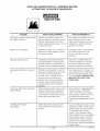
WHAT COULD HAPPEN
NOW TO PREVENT iT
Back feeding electricity through a
building's electrical system to the
outside utility feed lines could endanger repair persons attempting to
restore service.
Never backfeed electricity through
a structure's electrical system.
Attempting to connect to the incoming utility service could result in
electrocution.
Restoration of electrical service while
the generator is connected to the incoming utility could result in a fire or
serious damage if a isolator switch is
not installed.
To connect to a structure's electrical system in a safe manner,
always have a Double-Throw
Transfer Switch installed by a
qualified electrician and in compliance with local ordinances. (When
installing a Double=Throw
Transfer Switch, a minimum of
10 gauge wiring must be used,)
Failure to use a double throw transfer
switch when connecting to a structures electrical system can damage
appliances and WiLL VOiD the
manufacturers warranty.
3 -- ENG
NGP _70070
READ AND UNDERSTAND
ALL WARNINGS
BEFORE
ATTEMPTBNG TO OPERATE GENERATOR°
RBSK OF ELECTROCUTBON
AND FBRE .(¢ont'd}
HAZARD
WHAT COULD HAPPEN
Operation of generator in rain, wet,
icy, or flooded conditions.
Water is an excellent conductor of ebctricity! Water which comes in contact
with electrically charged components
can transmit electricity to the frame and
other surfaces, resulting in electrical
shock to anyone contacting them.
Operate generator
in a clean, dry,
well ventilated
area. Make sure
Contact with worn or damaged extension cords could result in ebctrocution.
Inspect extension cords before use
and replace with new cord if required.
Use of undersize extension cords could
Use proper size (wire gauge) cordset
for application see chart in the Assembly section of this manual
Use of worn damaged, undersized
or ungrounded extension cords.
result in overheating of the wires or attached items, resulting in fire.
Piacing generator on or against
higHy conductive surface, such as
a steei waikway or metai tool
HOW TD PREVENT iT
hands
are dry before touching
unit.
Use of ungrounded cordsets could prevent operation of circuit breakers and
result in electrical shock.
Always use a cordset having a
grounding wire with an appropriate
grounding plug. DO NOT use an
ungrounded plug.
Accidental
leakage of electrical current
could charge conductive
surfaces
in
contact with the generator.
Place generator on low conductivity surface such as a concrete
slab.
ALWAYS operate generator a
minimum of six feet from any
conductive surface.
Improper connection
generator.
to
Exceeding the load capacity of the generator by attaching too many items, or
items with very high load ratings to it
could result in overheating of some
items or their attachment wiring resulting in fire or electrical shock.
Read the load rating chart and instructions in the Wattage Calculation section, Make sure that the
summation of electrical loads for all
attachments does not exceed the
load rating of the generator.
Operation of unit when damaged, or
with guards or panels removed.
Attempting to use the unit when it has
been damaged, or when it is not functioning normally could result in fire or
ebctrocution.
Do not operate generator with mechanical or electrical problem. Have
unit repaired by an Authorized Service Center.
Removal of guarding could expose
electrically charged components and
result in ebctrocution.
Do not operate generator with protective guarding removed.
MGP 670070
of items
4:
ENG
READ AND UNDERSTAND
ALL WARNINGS
BEFORE
ATTEMPTBNG TO OPERATE GENERATOR°
RiSK OF FiRE
HAZARD
WHAT COULD HAPPEN
HOW TO PREVENT iT
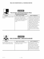
Attempting to fill the fuel tank while
the engine is running.
Gasoline and gasoline vapors can
become ignited by coming in contact
with hot components
such as the
muffler, engine exhaust gases, or from
an electrical spark.
Turn engine off and allow it to cool
before adding fuel to the tank.
Equip area of operation with a fire
extinguisher certified to handle
gasoline or fuel fires.
Sparks, fire, hot objects
Cigarettes, sparks, fires, or other hot
objects can cause gasoline or gasoline vapors to ignite.
Add fuei to tank in weii ventilated
area. Make sure there are no
sources of ignition near the
generator.
Improper storage of fuel
Improperly stored fuel could lead to
accidental ignition. Fuel improperly
secured could get into the hands of
children or other unqualified persons.
Store fuel in a OSHA approved
container designed to hold gasoline. Store container in secure
Materials
Operate generator in a clean, dry,
weii ventilated area a minimum of
four feet from any building, object
or waii. DO NOT OPERATE UNiT
iNDOORS OR iN ANY CON=
FINED AREA.
Inadequate ventilation for generator
placed
against
or near the
generator or operating the generator
in areas where the temperature
exceeds 104 ° R ambient (such as
storage rooms or garages) can
interfere with its proper ventilation
features causing overheating
and
possible ignition
buildings.
Tampering with factory set engine
speed settings.
of the materials
or
Engine speed has been factory set to
provide safe operation.
Tampering
with the engine speed adjustment
could result in overheating
of attachments and could cause a fire.
Overfilling the fuel tank fuel spillage.
Spilled fuel and its vapors can become ignited from hot surfaces or
sparks.
5 -- ENG
location to prevent use by others.
Never attempt to "speed=up" the
engine to obtain more performance. Both the output voltage
and frequency wiil be thrown out
of standard by this practice,
endangering attachments and the
user.
Use care in filling the tank to avoid
spilling fuel. Make sure fuel cap is
secured tightly and check engine
for fuel leaks before starting
engine. Move generator away
from refueling area or any spillage
before starting engine. Allow for
fuel expansion. Keep maximum
fuel level 1A inch below the tip of
the fuel tank. Never refuel with the
lvlGP
670070
READ AND UNDERSTAND
ALL WARNNNG$
BEFORE
Risk of in'u.Lu_r_z
and Pro eper_vtDa_ao_lLe When
Trans_q
Generater
HAZARD
Fire, hhaiation,
Surfaces
WHAT COULD HAPPEN
Damage to Vehicle
Fuei or oii can bak or spill and couid
resuit in fire or breathing hazard,
serious injury or death can resuit. Fuei
or oii baks will damage carpet, paint
or other surfaces in vehbbs or
traibrs.
RISK OF BREATHING
HAZARD
Gasoline engines produce toxic
carbon monoxide exhaust fumes.
- INHALATION
WHAT COULD HAPPEN
Breathing exhaust fumes will cause
serious injury or death.
HOW TO PREVENT iT
If generator is equipped with a fuel
shut-off valve, turn the valve to the
off position before transporting to
avoid fuel leaks. If generator is not
equipped with a fuel shut-off valve,
drain the fuel from tank before
transporting. Transport fuel only in
an OSHA approved container.
Always place generator on a
protective mat when transporting
to protect against damage to
vehicle from leaks. Remove
generator from vehicle immediately upon arrival at your destination
HAZARD
HOW TO PREVENT iT
Operate generator in clean, dry,
weii ventilated area. Never
operate unit in enclosed areas
such as garages, basements,
storage, sheds, or in any location
occupied
by humans or animals.
Keep children, pets and others
away from area of operating unit.
bIGP 670070
6 -- ENG
READ
AND UNDERSTAND
ALL WARNINGS
BEFORE
ATTEMPTBNG TO OPERATE GENERATOR°
RiSK OF UNSAFE
HAZARD
Operation
manner.
of generator
OPERATION
HOW TO PR_:V_:NT iT
WHAT COULD HAPPEN
in carebss
Review and understand all of
AH sources of energy include the
potential for injury. Unsafe operation
or maintenance of your generator
could lead to serious injury or death
to you or others.
the operating instructions and
warnings in this manual.
Become familiar with the
o
operation and controls of the
generator. Know how to shut it
off quickly.
Equip area of operation with a
fire extinguisher certified to
handle gasoline or fuel fires.
Keep children or others away
from the generator at all times.
Operation of voitage sensitive appiiances without a voitage surge protector.
Any gasoline operated household
generator wiii incur voltage variations
causing damage to voltage sensitive
appliances or could result in fire.
Always use a U.L listed voltage
sensitive surge protector to
connect voltage sensitive appliances such as TV, computer, or
stereo equipment, Failure to use
a U,L, listed voltage surge
protector will void the warranty
on your generator°
Notice: A multiple outlet strip is
not a surge protector make sure
you use a U.L listed voltage surge
9rotector.
Raising or suspending generators
equipped with iift rings improperly
Generator could fall causing serious injury or death to you or others.
Always use proper connecting
srocedures as described in this
Improper raising or suspending can
cause damage to the generator.
manual when connecting cables,
chains, or straps for raising or
suspending generators equipped
with lift rings.
Always use cables, chains, or
straps rated at 2000 Ibs working
load or more to raise or suspend
generator.
Operating generator wNe suspended
Generator wiii not operate properly
and wiii cause damage to the generator and could cause serious injury or
death to you or others.
7 -- ENG
Never operate generator while
suspended
or in an unievei position. Always operate generate on
a fiat, level surface.
lvlGP670070
REAO ANO UNDERSTAND
ALL WARNINGS
BEFORE
ATTEMPTBNG TO OPERATE GENERATOR°
RiSK OF HOT SURFACES
HAZARD
WHAT COULD HAPPEN
Contact with hot engine and
generator components.
Contact with hot surfaces, such as
engines exhaust components, could
result in serious burns.
RiSK OF MOVING
HAZARD
I _
HAZARD
Lifting a very heavy object.
rvIGP 670070
The generator contains parts which
rotate at high speed during operation.
These parts are covered by guarding
to prevent injury.
i
iT
During operation, touch only the
control surfaces of the generator.
Keep children away from the
generator at all times. They may
not be able to recognize the
hazards of this producL
PARTS
WHAT COULO HAPPEN
Contact with moving parts can
result in serious injury.
HOW TO PREVENT
HOW TO PREVENT iT
Never operate generator with
guarding or cover plates removed.
Avoid wearing loose fitting clothing
or jewelry which could be caught
by moving parts.
RiSK FROM LiFTiNG
WHAT COULD HAPPEN
Serious injury can result from attempting to lift too heavy an objecL
8 -- ENG
HOW TO PREVENT iT
The generator is too heavy to be
lifted by one person. Obtain
assistance from others before you
try to move it.
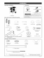
CARTON
CONTENTS
1 ° Parts
Bag
t = Owner"s Manua!
"t
*_
o TwisBeck
Plug
L14=30P
To be installed and/or used in
accordance with appropriate HocaHeHectricaHcodes
and reguHafions. Refer to enclosed instructions for
t o Generater
Parts and Parts Box for Wheel Kit Assembly
2 = Axle
1 = Cotter Pin
Spacers
1 = A×le End Cap
1 = Flat Washer
3/40D x 11/15 ID
2 = Wheels
3 = 5/15=18 x 3/4 ""
2 = Bracket
7 = 5/16=18
Lock Nuts
Cap Screws
4 = 5/1(;=18 x 1 3/4 ""
Cap Screws
2 = HandBe Assemblies
NOTE: The axBe is stored
shipping purposes
Parts Bag for Battery
1 = 5/16=18 x 3.4 ""
__11
in one handRe assembly
- _le
t = Leuvered
DefJector
for
Neat
4_ Screws,
HH #8=32
installation
1 = Star Washer
1 = 5/16=18
Lock Nuts
Cap Screws
O
2 = Wing Nuts
O
1 = ""L"" Battery
2 = Battery
Bracket
Bolt Hold Down
1 = Red Positive Battery Cable (red} with battery boots
9 -- ENG
1 = Black Negative
Battery
Cable (black)
MGP 670070
Read owner's manual. Do not attempt to operate equipment until you have read Owner's
Manual for Safety, Assembly, Operation, Maintenance, Storage Instructions.
TOOLS
121111-
NEEDED
Handle Assembly
secured te top frame
FOR ASSEMBLY
Box Cutter or Knife
1/2" Wrenches
Pair Wire Pliers
Hammer
1/2" Socket and Socket Wrench
1/4" Socket and Socket Wrench
1 - 1" thick x 1 ' square piece of wood
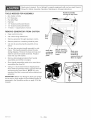
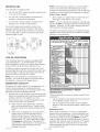
REMOVE
GENERATOR
FROM
CARTON
Open carton from top.
Cut carton along dotted lines.
o
Remove generator through opening in carton.
o
Remove parts box containing wheel kit parts.
Cut wire tie securing handle assembly to top
frame.
Cut wire ties securing handle assembly to side
frame. This handle assembly stores the axle
during shipping.
Remove the base end cap and
slide the axle from handle assembly.
Replace
base end cap with washer.
Remove all packaging
material from
assemblies
and oil filter on engine.
o
Place handle
assembling
assemblies
the wheel
handle
aside to be used when
kiL
Using a 1/2 inch socket remove shipping block
from under the generator head. Unscrew the bolt
and remove the wood block.
NOTE: It is very
important
that this is removed before starting your
generator.
iMPORTANT:
Before any attempt to start your generator be sure to check engine oil (See Adding Engine Oil
paragraph
in the Operation section on page 15 of this
manual,)
blap 670070
10 -- ENG
1
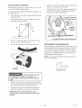
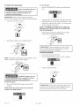
INSTALLATmON
OF BATTERY
Attach one end of the negative (black) cable
negative (-) terminal on the battery.
Recommended
Battery for Electric Start: 12V - 45 A H.
or 210 CCA (Cold Cranking Amps)
Attach the other end of the negative (black) cable
to the frame as shown.
Install the star washer
between the cable and the frame.
Purchase battery and battery hardware separately, not
included with unit.
Place battery in rack with terminals facing towards
generator head.
o
to the
(=} Negative Battery
Cabme Connection
Place battery bracket (A) over battery as shown
(opposite battery terminals).
Negative
(=} Battery
Cable
(-} Negative
*
Battery
Cable
Cenneetien
Piace "L" boit (B) through top and bottom brackets and secure with wing nut (C).
GROUNDmNG
Locate the solenoid on the left side of the unit.
THE GENERATOR
A grounding lug is supplied with the generator for use
when required by local electrical ordinances. Refer to
article 250 of the National Electrical Code to clarify
any needed grounding information. Your local electric
company or a certified electrician should be able to
help you with this information.
NOTE: Your engine is already grounded to the frame
by a grounding strap.
O
Grounding
Lug
To Prevent sparks connect
the red (positive} cable to the positive (+)
terminal before connecting the black negative
cable.
Remove the nut from the solenoid post and place
one end of the positive (red) battery cable onto the
posL Reassemble nut and tighten securely.
Attach the other end of the positive (red) battery
cable to the positive (+) terminal on the battery.
NOTE: Make sure red battery boots cover
positive battery cable terminals at battery and
solenoid
11 -- ENG
lvlGp670070
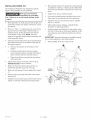
mNSTALUNG
WHEEL
KmT
Place the fiat washer (7) against the wheel bushing
and slide the cotter pin (4) through the drilled hole
of the axle (2). Bend the cotter pin (4) to secure in
place.
The Craftsman Wheel Kit was designed to greatly
improve the portability of your generator.
kit. Failure
engine.
Drain gas and oil before
assembling
the portability
to do so will cause damage
to the
Tighten lock nuts on wheel brackets.
Line up the handle brackets with the hobs in the
frame near the receptacle end of the generator.
Install hex screws (1O) and lock nuts (9). Tighten
with a 1/2"wrench.
Place generator on level ground; drain all gas and
oil from the engine (see engine manual for correct
procedure).
Place a 1" thick x 1' square piece of wood on the
ground in front of the engine. With the help of
another person, tilt the generator and rest the
recoil starter on the wood. NOTE: This will
support the gasoline engine during assembly and
make assembly easier.
o
With another person helping, carefully flit the
generator to operating position.
Install Iouvered heat deflector to the muffler using
four #8-32 HH screws. Orient heat deflector so the
vent openings are pointing toward the rear of the
engine.
iMPORTANT: To prevent damage or possible hazards,
do not orient deflector in any other position.
Using two screws (8) and two lock nuts (9) install
the wheel bracket (5) on the bottom right side of
the engine support.
a.
Remove the Iocknut on the bottom of the
isolator.
b.
Position wheel bracket onto the existing
screw, lining up hobs in bracket with hobs in
frame. Secure with the removed IocknuL
The portability
kit is now ready for use.
14
c.
10
Place screw (8) into second hob and secure
with iocknut (9).
10
o
Tap the axle cap (6) on the end of the axle (2),
without the hole, using a hammer.
Siide one wheei (1) onto the axb with the extended hub pointed away from axb cap.
Siide one axb spacer (3) down against the wheei
(1).
Slide the axle (2) through the hobs in the wheel
brackets (5).
Install the second axle spacer (3) then the second
wheel (1) with the extended hub facing inward.
bIGP670070
12 -- ENG
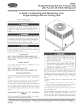
ENGINE
SUPPORT
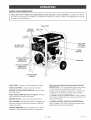
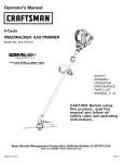
KNOW YOUR
GENERATOR
Read this Owner's Manual and Safety Rules before operation of your Generator. Compare this illustration with your generator to famiHiarize yourseHf with the location of various controHs and adjustments. Save the
manuaH for future rderences.
FUEL TANK
CIRCUIT
BREAKERS
FUEL CAP
FUEL SHUT
OFF VALVE
(not shown}
120 VOLT GFCI
RECEPTACLE
CHOKE
CONTROL
120 VOLT 3£PRONG
TWISTLOCK
RECEPTACLE
MUFFLER
240 VOLT 4-PRONG
TWISTLOCK
RECEPTACLE
ON/RUN/START
SWITCH
FUEL TANK- Capacity of 7 US gallons/26.5
CHOKE CONTROL-
Liter&
Used to start coHd engine.
ENGINE OFF/RUN/START
SWITCH- Used to start
GFCI (Ground Fault Circuit interrupter} 120 VOLT
RECEPTACLE- GFCI receptacles reduce the chance
of electrical shock by tripping it's built in circuit
breaker when it senses an imbalance in currenL This
and stop engine.
receptacle is protected by 30 amp circuit breaker.
FUEL VALVE LEVER {located on engine} - Used to
shut off the flow of fueHto the engine.
3= PRONG 120 VOLT RECEPTACLE- Used to supply
3500 watts of electrical power and is protected by 30
amp circuit breaker.
ENGINE OiL FILL- Check and fiH engine with oil
AIR CLEANER- hdudes filter element cartridge and
foam pre-cleaner that limits the amount of dirt that
enters the engine.
4-PRONG 240 VOLT TWISTLOCK
RECEPTACLE -
Used to supply 7000 watts of electrical power and is
protected by 30 amp circuit breaker.
CiRCUiT BREAKER- Each receptacle has a circuit
breaker to protect the generator from overloading.
13 -- ENG
NGP670070
Your generator is equipped with:
one 120 voHtGFCI dupHex receptacle
a 15 amp circuit breaker
protected by
one 120 voHt3-prong twisflock receptacle protected by a 30 amp circuit breakers
one 240 voHt4-prong twisflock receptacle protected by two 30 amp circuit breakers
The circuit breakers are provided to protect the
generator against eHectricaHoveHoad. If the circuit
breaker trips, unpHug eUectricaHHoadfrom receptacle.
Let circuit breaker cooHdown and then push circuit
breaker button to reset.
NOTE: Some inductive appHiances and tooHs will Hist
on the motor name pilate, the starting and running
voHtage and amperage requirements. Use the following
formuHa to convert voltage and amperage to wattage:
(Volts X Amp = Watts}
Always start your largest electric motor first, and
then plug in other items, one at a time.
NOTE: On 120-volt loads the maximum starting wattage should NOT exceed one half of the rated generator
wattage. Example: a 7000 rated wattage generator =
3500 maximum starting wattage.
The guide is provided to assist you in determining the
appliances and tools that can be ran with the wattage
capacity of your generator.
®
RESET
REMETTRE
LOW OraLSHUTDOWN
Your Craftsmangeneratorengine isequipped with
Low OilShutdown. Low OilShutdown isa safety
devicedesignedto protectyour enginefrom damage
intheeventthe oillevelinthe crankcaseislow.
If while the engine is running, the oil gets low, it will
automatically shut itself down and will not restart until
the oil is added. If the oil is low before start-up, the
generator will not start until oil is added.
NOTE: The Low Oil Shutdown mechanism is very
sensitive. You must fill the engine to the full mark on
the dipstick to inactivate this safety device.
GENERATOR
CAPACmTY
Exceeding the rated capacity of your generator can
result in serious damage to your generator and
connected electrical devices. You should observe the
following to prevent overloading the unit:
Starting and running wattage requirements should
always be calculated when matching a generators
wattage capacity to the appliance or tool.
There are two types of electrical appliances that
can be powered by your generator:
A.
Extension
Cord
When using an appliance OFtool at a considerable
Items such as refrigerators, air compressors,
distance from the generator, a 3-wire extension cord
washer, dryer, and hand tools that use an
electrical motor have an "inductive load".
that has a 3-blade grounding plug and a 3-slot receptacle that accepts the tool's plug MUST be used in
Inductive load appliances and tools require
order to reduce the risk of electrical shock. A cord of
approximately 2 to 4 times the listed wattage
adequate size must be used. A minimum of 12 gauge
for starting the equipment. This initial load
wire size with at least a 20 amp draw can be used.
only lasts for a few seconds on start-up but is
When amperage exceeds 20 amps a 10 gauge wire
very important when figuring your total
size should be used.
wattage to be used.
670070
14 - ENG
B.
MGP
Items such as radios, light bulbs, television
sets, and microwaves have a "resistive load".
Starting wattage and running wattage are the
same.
There are basically two ways to obtain electricity form
a generator:
Use of extension cords directly from the generator
to the appliance, lights, tools, etc.
Use of a double-throw transfer switch installed
directly to the main electrical supply outside of the
house.
Full
An extension
cord that is hot
to the touch is oveHoaded,
Repair or replace damaged
Connecting
Supp(y
Generator
extension
To Main
cords
E(ectrica(
Potential hazards exist when a ebctrba] generator is
connected to the main ebctrba( supply coming into
the house, It is at that point that the generator could
feed back into the utility company's system causing
possible electrocution of workers who are repairing
electrical lines. To avoid back feeding of electricity into
utility systems, a double=throw transfer switch
should be installed between the generator and utility
power. This device should be installed by a licensed
electrician and in compliance with all local electrical
codes.
Replace dipstick firmly.
NOTE: When adding oil to the engine crankcase, use
a high quality detergent oil classified "For Service
SF,SG,SH,SJ" rated SAE 30 weight. Use no special
additives. Select the oil's viscosity grade according to
your expected operating temperatures.
__
SAE Viscosity
NOTE: When installing a Doubb-Throw Transfer
Switch, a minimum of 10 gauge wiring must be used.
BEFORE
START[NG
ENG[NE
STARTING
Engine
TFMPERATURE
RANGE
I
ANTICIPAI
__
I
FD
BEFORE
NEXT
OIL
CHANGE
Gasoline
Always check engine oil level
before every start. Running
engine low of oil or out of oil could result in
serious damage to the engine.
Adding
I
Grades
To add gasoline:
Remove gas cap.
Oil
Your generator has been shipped without oil in the
engine. Begin by removing the oil dipstick and plug.
Start pouring the oil in slowly.
The engine will hold approximately 48 ounces/1 A liters
of oil
To check oil:
Place engine in a level position.
fill and dipstick.
Clean around oil
Add unleaded gasoline, slowly, to fuel tank.
Use clean, fresh, regular unleaded gasoline with a
minimum of 85 octane. Use unleaded fuel only. Do not
use gasoline which contains Methanol. Never mix oil
with gasoline.
Remove dipstick and wipe clean with cloth.
Never
Push dipstick back in and remove to check oil.
Keep oil level at FULL line on dipstick.
fill fuel
tank
com-
pmetemy, Fimm
tank to 112" bemow the bottom
of the
fimmerneck to provide space for fuem expansion,
Wipe any fuel spillage
from engine and equipmerit before starting
engine,
Do not overfill
Replace
gas cap.
Never
Never
h_n
fill fuel tank
when
fill fuel tank
indoors,
engine is running
fillin
fuel tank.
or
To add oil:
Remove oil fii[ cap.
@
Pour oii siowiy and fiii to FULL iine on dipstick.
not overfiii.
Turn engine
Do
15 -
engine cool
gas cap,
ENG
at least 2 minutes
OFF and let
before
removing
MGP670070
For recoil start:
To Start Your Generator
Never
run engine
in enclosed,
poor ventilated
areas.
exhaust
contains
carbon
monoxide,
ordoriesa
and deadly
indoors
Hace OFF/RUN/START switch in the RUN position.
or
Engine
an
gas.
iMPORTANT: Make sure the battery is property
serviced, fully charged, and assembbd before starting.
Grasp handle on rope starter and pull slowly until
resistance is fell Let the rope rewind slowly. Pull
rope with a rapid full arm stroke. Let rope rewind
slowly. Repeat if necessary.
Open the fuei shut-off vaive.
NOTE: IF ENGINE OIL LEVEL IS TOO LOW, ENGiNE WiLL NOT START. CHECK OiL LEVEL AND
ADD IF NECESSARY.
When engine warms up, gradually push choke
control in to the NO CHOKE position.
®
Pull choke control out to CHOKE position.
iMPORTANT: Allow generator to run at no load
for 5 minutes upon each initial start-up to allow
engine and generator to stabilize.
STOPPmNG
*
J
ENGINE
Disconnect all electrical loads.
Turn OFF/RUN/START switch to "OFF" position.
NOTE: No choke is required on warm engines.
choke control in to start a warm engine.
Push
Close fuel shut-off valve.
You MUST unplug any load
®
J
from the generator before starting to prevent
permanent damage to any appliances.
For emectric start:
Place OFF/RUN/START switch in the START
position.
NOTE: When the engine starts the switch wimm
remain in the RUN position.
bIGP670070
iMPORTANT: Never store enginewith fuel in tank,
indoors, or in enclosed, poorly ventilated areas or
where fuel fumes may reach an open flame.
16 -- ENG
1
|
1
CONNECTmNG
ELECTRmCAL
Let engk_e run and warm
starting with no ebctrbai
Connect
ioads in the following
LOADS
up for five minutes
ioad.
manner
Voltage sensitive equipment
should be the last
equipment
connected
to the generator.
Plug
voltage sensitive appliances
such at TV's, VCR's,
microwaves,
ovens, computers,
and cordless
telephones
into a UL listed voltage surge protector, then connect the UL listed voltage surge
protector
to the generator.
after
to prevent
Connect inductive load equipment first, inductive
loads consist of refrigerators, freezers, water
pumps, air conditioners, or small hand tools.
Connect the items that require the most wattage
first.
Connect the lights nexL
iMPORTANT:
You should always add up the rated
watts of all lights, tools and appliances
you are
powering
at one time. This total should not
exceed the rated capacity of you generator or
circuit breaker rating of the receptacle
supplying
power.
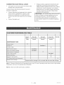
CUSTOMER
RESPONSBBBLBTRES TABLE
Every 8
Hours or
Daily
MAINTENANCE
Every 25
Hours of Every
Season
Every 50
Hours of Every
Season
Every 100
Hours of Every
Season
Monthly
TASK
X
Check oil level
See Note 1
Change oil
X
Change oil filter
Service air pre-cbaner
See Note 2
Service air cleaner cartridge
See Note 2
X
Spark arrester ( if equipped)
See Note 2
Clean cooling system
Check spark plug
X
Replace in=line fuel filter
X
X
GFCI (ground fault circuit interrupter)
Prepare unit for storage
Prepare unit for storage
if it is to remain idle for more than 30 days,
Note 1: Change oil after first five (5) operating hours, every 25 hours if operating under heavy load or high ambient
temperature, and every 50 operating hours thereafter.
Note
2: Clean
more often
under dusty conditions.
17 -- ENG
lvlGP670070
GENERAL
RECOMMENDATmONS
The warranty of the generator does not cover items
that have been subjected to operator abuse or negligence+ To receive full value from the warranty, operator must maintain the generator as instructed in this
manual+
I
Plug
J
J
Some adjustments wiii need to be made periodically to
maintain your generator+
GENERATOR
Your generator should be kept clean and dry at all
times+ The generator should not be stored or operated in environments
that include excessive moisture,
dust or any corrosive
vapors+ If these substances
are
on the generator, clean with a cloth or soft bristle
brush+ Do not use a garden hose or anything with
water pressure to clean the generator+
Water may
enter the cooling air dots and could possibly damage
the rotor, stator and the internal windings of the
generator head+
All adjustments
manual should
Used oil is a hazardous
IVIAmNTENANCE
waste product. Dispose of used oil properly,
Do not discard with household waste. Check
with your local authorities, service center, or
dealer for safe disposal/recycling
facilities.
o
Reinstall drain plug+ Remove oil fiii cap+
@
Fiii the crankcase with new oil of the proper type
(See Adding Engine Oil in the Operation section),
to the FULL mark on the dipstick. Always check
the level with the dipstick before adding more oil+
in the Maintenance
section of this
be made at least once each season+
FULL
ENGmNE IVIAmNTENANCE
NOTICE:
Maintenance,
replacement
or repair of
the emission
control
devices and systems
may be
performed
by any nonroad
engine repair establishment or individual.
However,
to obtain no charge
repairs under the terms and provisions
of the
engine manufacturers
warranty
statement,
any
service or emission
control
part repair or replace=
merit must be performed
by a factory
authorized
dealer.
Oil
+
+
Reinstall the oil fiii cap or plug and tighten securely+
Change
Oil level should be checked prior to each use and
at bast every 8 hours of operation+ To check oil
see Adding Engine Oil paragraph in the Operation section of this manual+
Changing
Engine
Oil Filter
Change oil filter after every 100 hours or every season.
+
Drain engine oil and remove oil filter.
Used oil is a hazardous
OH
waste product. Dispose of used oil properly,
Do not discard with household waste. Check
For a new engine, change oil after the first 5 operating
hours. Thereafter, change oil after every 50 hours of
operation.
Change the oil while the engine is still warm. The oil
will flow freely and carry away more impurities. Make
sure the engine is level when filling, checking or
changing oil+
with your local authorities, service center, or
dealer for safe disposal/recycling
facilities,
+
Before installing new filter, lightly oil filter gasket
with fresh, clean oil+
Change the oil as follows:
+
To keep dirt, grass clippings, etc+ out of the
engine, clean the area around the drain plug and
dipstickbdore
removing it+
+
Disconnect spark plug wire and keep away from
spark plug+ Disconnect battery at negative
terminal+
+
With engine off but still warm, remove oil drain
plug and drain oil into appropriate receptacle+
MGP 670070
Fimter
o
18 -- ENG
Screw filter on by hand until gasket contacts oil
filter adapter+ Tighten 1/2 to 3/4 turn more+
Addfreshoil SeeAdd EngineOil intheOpera=
tier sectionof thismanual
Startandrunengineat idHe
to checkforHeaks.
Stopengine.Re-checkoiHHeveH,
addoiHif required.
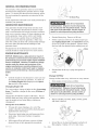
Air Cleaner
Clean
Cooling
System
Debris may cHog the engine's air cooHing system_
Remove bHower housing and dean area shown to
prevent overheating and engine damage.
Clean
Clean and Replace
Spark
Plug
Check spark pHugyearHyor every 1O0 operating hours.
CHean area around spark pHug.
Remove and inspect spark pHug.
RepHace spark pHugif eHectrodes are pitted, burned
or porceHain is cracked.
Plate
Check electrode gap with wire feeler gauge and set
gap _030 if necessary.
Install spark, tighten securely.
Pre=cleaner
Body
Remove knob and plate. Carefully remove air
cleaner assembly to prevent debris from entering
carburetoR
Replace
To clean pre-cleaner and cartridge:
Fuel ran-Line Filter
Disconnect spark plug wires and keep away from
spark plugs.
Pre=cleaner
Separate from cartridge and wash in liquid
detergent and water.
i Drain fuel tank or close fuel
Squeeze dry in a clean cloth.
shut=off valve before replacing
Saturate in engine oil. Squeeze in clean,
absorbent cloth to remove all EXCESS oil.
fuel filter.
1
Replace in-line fuel filter
In=line Fuel Filter
Cartridge
Gently tap on a flat sudace.
,
Reassemble clean (or new ) pre-deaner
clean (or new) cartridge.
on
Reinstall air cleaner assembly, plate and knob
in body.
Replace cover and reattach clips to body.
19 -- ENG
lvlGP670070
GFCm receptacme
mnterrupter}
(Ground
Faumt Circuit
For maximum protection against ebctrbai
GFCI shouid be tested montHy.
shock the
To test:
1.
2.
Depress the TEST button. The RESET button
shouid extend. If the RESET button does not
extend, notify a Authorized Service Center.
To restore power, depress
into the GFCI unit untii an
reset properiy, the RESET
surface of the test button.
in, the power is ON.
z m
4H
the RESET button firmiy
audiMe chick is heard. If
button is flush with the
When the button stays
CARBURETOR
The carburetor of your generator is pre-set at the factory. The carburetor shouM not be tampered with. If your
generator is used at an aifitude in excess of 4000 feet
performance may be affected. If so consuit with your
nearest Craftsman Service Center regarding high aititude
set changes.
©
Over-speeding
your engine above factory high speed
ting can be dangerous
and could possibly
cause
sonai injury or property damage. If you believe the
gine is running too fast or slow, take your generator
Authorized
Craftsman
Service Center for repair and
setperento a
ad-
GOVERNOR
Your engine governor maintains the constant operating
speed of your generator.
DO NOT tamper with the engine governor
which is factory set for proper engine
speed.
Place rag over spark plug hob and pull the recoil a
few times to lubricate the combustion chamber.
If you are going to store your generator for more than
30 days, use the following information as a guide to
prepare the generator for storage.
Never store generator with
in the tank indoors or
in enclosed, poorly ventilated areas, where
fumes can reach an open flame, spark or pilot
light as on a furnace, water heater, clothes
dryer or other gas appliances,
Engine
Replace the spark plug, but do not connect the
spark plug wire.
NOTE: If a fuel stabilizer is not used, all gasoline must
be drained from the tank and carburetor to prevent gum
deposits from forming on these parts and causing possible malfunction of the engine.
Clean the generator as outlined in the Generator
Maintenance paragraph on page 18.
Preparation
Check that cooling air slots and openings on
generator are open and unobstructed.
Add fuel stabilizer to fuel tank to minimize the
formation of fuel gum deposits during storage.
Run engine at least 10 minutes after adding
stabilizer to allow it to enter the fuel system.
Disconnect the spark plug wire and remove the
spark plug.
Add one teaspoon of oil through the spark plug
hob.
bIGP670070
Battery
Store battery as described by the battery manufacturer.
NOTE: After storing battery for a long period of time it
may lose it's charge. If the battery loses it's charge,
manually start the engine with the battery connected.
The engine wiii recharge the battery as it runs.
20 -- ENG
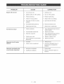
PROBLEM
Engine wifl not start
No electHcM
output
CA USE
1.
Low on fuei or oil
1, Add fuel or oii,
2.
Ignition switch in "Off" position.
2, Turn to "ON" position
3.
Fauityspark
3,
4.
Choke in wrong position.
4, Adjust choke accordingly,
5.
Fuei shut-off vaive in dosed
position.
5, Open fuel shut-off valve,
6.
Unit ioaded during start-up.
6, Remove load from unit,
7.
Spark piug wire ioose,
7, Attach wire to spark plug,
1.
Fauity receptacb.
1.
piug,
Replace spark plug,
Have Authorized
Center
2.
Circuit breaker kicked out.
2.
3.
Defective capacitor.
3.
Depress
circuit breaker
Generator overheating the
circuit breaker depressed
and reseL
Have Authorized
Center
Repeated
tripping
Sears Service
replace.
replace
Sears Service
capacitor.
4,
Faulty power cord.
4.
Repair or replace
5,
GFCI receptacle circuit breaker
kicked out,
5.
Depress
and reseL
1,
Overload
Reduce
load.
2,
Faulty cords or equipment.
2, Check for damaged,
1,
Generator overloaded,
1, Reduce load,
2,
Insufficient ventilation,
2, Move to adequate supply of
fresh air,
.
21 -- ENG
cord.
bare, or
frayed wires on equipment.
Replace.
NGP670070
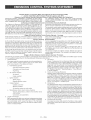
Briggs&
Stratton
Corporation
(B&S), the California
Air Resources
Board (CARD)
and the United States Environmental
Protection
Agency (U.S. EPA)
Emission
Control System Warranty
Statement
(Owner's
Defect Warranty
Rights and Obligations}
EMISSION CONTROL WARRANTY COVERAGE IS APPLICABLE
TO CERTIFIED
MODEL YEAR 1997 AND LATER ENGINES
TO CERTIFIED ENGINES PURCHASED IN CALIFORNIA IN 1995
WHICH ARE PURCHASED
AND USED ELSEWHERE
IN THE
AND THEREAFTER,
WHICH ARE USED IN CALIFORNIA,
AND
UNITED STATES.
California
and United States Emission
Control Defects Warranty
Statement
The California Air Resources Board (CARB), U.S. EPA and B&S are
the periods of time listed below, provided there has been no abuse, nepleased to explain the Emission Control System Warranty on your
glect or improper maintenance of your small off-road engine.
model year 2000 and later small off-road engine (SORE). In California,
'four emission control system includes parts such as the carburetor,
new small off-road engines must be designed, built and equipped to
air cieaner, ignition system, muffter and catalytic converter. Aiso inmeet the State's stringent anti-smog standards. Elsewhere in the
cluded may be connectors and other emission related assemblies.
United States, new non-road, spark-ignition engines certified for model
Where a warrantable condition exists, B&S will repair your small offyear 1997 and later, must meet similar standards set forth by the U.S.
road engine at no cost to you including diagnosis, parts and Iabor.
EPA. B&S must warrant the emission control system on your engine for
Briggs & Stratton Emission
Control Defects Warranty
Coverage
Small off-road engines are warranted relative to emission control
below. If any covered part on your engine is defective, the part wiil be
parts defects for a period of two years, subject to provisions set forth
repaired or replaced by B&S.
OwneCs Warranty,
Responsibilities
As the smalt off-road engine owner, you are responsible for the perYou are responsible for presenting your smalt off-road engine to an
formance of the required maintenance listed in your Operating and
Authorized B&S Service Dealer as soon as a problem exists. The
Maintenance
Instructions. B&S recommends that you retain atl your
undisputed warranty repairs should be completed in a reasonable
receipts covering maintenance
on your smatl off-road engine, but
amount of time, not to exceed 30 days.
B&S cannot deny warranty sotely for the lack of receipts or for your
If you have any questions regarding your warranty rights and refailure to ensure the performance
of alt scheduled maintenance.
sponsibilities, you should contact a B&S Service Representative
at
1-414-259-5262.
As the smail off-road engine owner, you should however be aware
The emission warranty is a defects warranty. Defects are judged on
that B&S may deny you warranty coverage if your smalt off-road engine or a part has faited due to abuse, negtect, improper maintenormal engine performance. The warranty is not related to an in-use
emission test.
nance or unapproved modifications.
Briggs & Stratton Emission
ControU Defects Warranty
Provisions
The following are specific provisions relative to your Emission Control Defects Warranty Coverage. It is in addition to the B&S engine warranty
for non-regulated
engines found in the Operating and Maintenance
Instructions.
1. Warranted Parts
3. No Charge
Coverage under this warranty extends only to the parts listed beIow (the emission control systems parts) to the extent these
parts were present on the engine purchased.
a.
Fuel Metering
System
Cold start enrichment
Carburetor
system
and internal
parts
Fuel Pump
b.
Air Induction System
Air cleaner
c.
Ignition System
4.
Intake manifold
Spark plug(s)
Magneto
d.
Catalyst
ignition
system
5.
System
Catalytic converter
Exhaust manifold
Air injection
e.
Miscellaneous
system or pulse valve
Items Used in Above
Vacuum, temperature,
and switches
Connectors
2.
Systems
position, time sensitive
valves
and assemblies
Length of Coverage
B&S 'warrants to the initial owner and each subsequent purchaser
that the Warranted Parts shatl be free from defects in materials
and workmanship
which caused the failure of the Warranted
Parts for a period of two years from the date the engine is delivered to a retail purchaser.
MGP670070
6.
22 -- ENG
Repair or replacement of any Warranted Part will be performed
at no charge to the owner, including diagnostic labor which leads
to the determination
that a Warranted Part is defective, if the
diagnostic work is performed at an Authorized
B&S Service
Dealer. For emissions warranty service contact your nearest Authorized B&S Service Dealer as listed in the "Yellow Pages" under "Engines, Gasoline," "Gasoline Engines," "Lawn Mowers,"
or similar category.
Claims and Coverage Exclusions
Warranty ctaims shall be filed in accordance with the provisions
of the B&S Engine Warranty Policy. \Narranty coverage shall be
excluded for failures of Warranted Parts which are not original
B&S parts or because of abuse, neglect or improper maintenance as set forth in the B&S Engine Warranty Policy. B&S is not
liable to cover failures of Warranted Parts caused by the use of
add-on, non-original, or modified parts.
Maintenance
Any Warranted Part'which is not scheduled for replacement as required maintenance or which is scheduled only for regular inspection to the effect of 'repair or replace as necessary" shall be warranted as to defects for the warranty period. Any Warranted Part
which is scheduled for replacement as required maintenance
shall be warranted as to defects only for the period of time up to
the first scheduled replacement for that part. Any replacement
part that is equivalent in performance and durability may be used
in the performance of any maintenance or repairs. The owner is
responsible for the performance of all required maintenance, as
defined in the B&S Operating and Maintenance Instructions.
Consequential
Coverage
Coverage hereunder shatl extend to the failure of any engine
components caused by the faiture of any Warranted Part stitt under warranty.
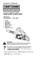
3
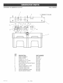
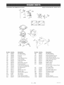
TORQUE
1
20=25 IN=LBS
TORQUE
14
11
TORQUE
20=30 IN=LBS
AFTER SETTING
ENGINE SPEED
_..
4
25=30 IN=LBS
1
TORQUE
120=144 IN=LBS
13
TORQUE
120=144 IN=LBS
KEY
NO.
1
2
3
4
5
6
7
8
9
10
11
12
13
14
TORQUE
20=25 IN=LBS
DESCRIPTION
FUEL TANK SCREWS
FUEL TANK
FUEL CAP
HEAT SHIELD
FRAME ASSEMBLY
END COVER
SCREW #10-24 x 9/16
FUEL HOSE
FUEL LINE CLAMP
SCREW, HEX CAP 5/16-18 x 1.25
SCREW #10-32 x 1/2
GROUND LUG
SCREW 5/16-18UNC 2A
WASHER .8750D .3751 D .083THK
23 -- ENG
PART NUMBER
91895680
GS-0795
GS-0443
GS-0271
GS-0913
GS-0077
SSF-553-1
GS-0225
GS-0227
SSF-605
GS-0107
GS-0117
95829230
SSN-632
MGP670070
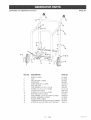
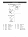
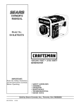
CRAFTSMAN
7000
GENERATOR
9t 9°670070
GENERATOR
21"
TORQUE
60=70 IN=LBS
20
9
INSERT
17 /16
18
TORQUE
IN SQUARE
HOLES
14
15
120=144 IN=LBS
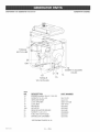
KEY
NO,
14
15
16
17
18
19
19A
20
21
22
23
DESCRIPTmON
PART NUMBER
ENGINE (model # 294447-1042-E1)
SCREW 5/16-18 x 3/4
GROUND STRAP
LOCK WASHER
LOCK NUT
ISOLATOR
ISOLATOR
REAR ISOLATOR SPACER
SCREW 1/4-20 x 3/4
FUEL SHUT-OFF VALVE
DRAINCOCK GROMMET
SS-12-CD
GS-0118
SSN-1619-ZN
SSF-8150
GS-0033
GS-0033
GS-0492
91895680
GS-0437
GS-0446
*SEE ENGINE PAGES 30-36
MGP670070
24 -- ENG
ASSEMBLY
CRAFTS_,_AN 7000
GENERATOR
GENERATOR
0t0o670070
1
/
/
ORENT
WITH
VENTS
DOWNWARD
AS
HEAD ASSEMBLY
SHOWN
2
5
3
TORQUEUNTILTHREADSRUNOUT
TORQUE
204-264
IN-LBS
/
9
10
/ /
12 TORQUE
60-70
IN-LBS
f
113
116
SHOWN
REFERENCE
_17
FOR
TORQUE
30-40 IN-LBS
ONLY
8 TORQUE
120-144
IN-LBS
\
\
\
\
\
\\
21
INSERT
GROOVE,
SCALE
CAPACITOR
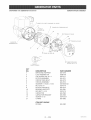
KEY
NO,
1
2
3
4
5
6
7
8
9
10
11
12
16
17
21
INTO O-RING
PART OF 10
1:1
WIRING
DESCRIPTION
DRIVE END ADAPTER
LOCK WASHER 3/8
CAP SCREW 3/8-16 x 1
ROTOR ASSEMBLY
STATOR THRU BOLT
STATOR ASSEMBLY
WASHER 11/16OD x 11/32
NUT 5/16-24
ROTOR THRU BOLT
BEARING SUPPORT
HEX NUT 1/4-20
CAPACITOR
CAPACITOR BRACKET
SCREW 10-32
O-RING
PART NUMBER
GS-0076
SSN-619
SSF-577
GS-0571
GS-0273
GS-0572
SS-6506-CD
SSF-576
GS-0274
GS-0861
SSF-575
GS-0592
GS-0595
SSF-553-1
GS-0862
ITEM NOT SHOWN
DIODES
GS-0082
25 -- ENG
NGP670070
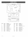
CRAFTSMAN
7000
GENERATOR
9t 9°670070
PANEL ASSEMBLY
3
TORQUE
12
KEY
NO.
1
2
3
4
5
6
7
8
9
10
11
12
MGP670070
DESCRmPTION
PANEL ASSEMBLY
PANEL COVER
SCREW 10 - 9 X .50
SCREW #6-32 X .5 TORX
NUT, SPEED #6 - 32
120V DUPLEX GFCI RECEPTACLE
NUT, HEX JAM
CiRCUiT BREAKER 15 AMP
3 PRONG TWISTLOCK
4 PRONG TWISTLOCK
CIRCUIT BREAKER 30 AMP
26 -- ENG
PART NUMBER
GS-0928
GS-0017-1
SSF-3156
SSF-583
SSF-584
GS-0806
SSF-595
GS-0024
GS-0021
GS-0455
GS-0026
GS-0046
OF 10 BN=LBS.
CRAFTSMAN
70GG GENERATOR
9t9,670070
WHEEL
KiT
14
13
10
10
KEY NO,
DESCRiPTiON
PART NO,
1
2
3
4
5
6
7
8
9
lO
11
12
13
14
15
16
WHEEL (2 USED)
AXLE
AXLE SPACER(2 USED)
COTTER PiN
WHEEL BRACKET(2 USED)
AXLE END CAP
FLAT WASHER, 3/40D X 11/16 ID
SCREW, 5/16-18 X 1-3/4 (3 USED)
LOCK NUTS (7 USED)
SCREW, 5/16-18 X 1-3/4 (4 USED)
BASE END CAPS (2 USED)
FLAT WASHER, !-5/16 OD X 5/8 ID (2 USED)
HANDLE ASSEMBLY (2 USED)
HANDLE GRiP (2 USED)
LOUVERED HEAT DEFLECTOR(NOT SHOWN)
SCREW, HH #8-32 (4 USED) (NOT SHOWN)
GS-0583
GS=0586
GS-0213
SSN=622
GS-0217=1
SSF=591
SSN=623
SS-12-CD
SSF-8150
SSF=999-1
GS=0221
91890228
GS-0584
GS-0220
GS=0597
SUDL-9=I
27 -- ENG
NGP670070
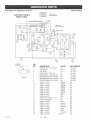
CRAFTSMAN 7000 GENERATOR 9t0=670070
WmRING DIAGRAM
OOOG
DOOO
OOOG
CONTROL
PANEL
REAR VI EW
TO ENGINE
STARTER
TO ENGINE
REAR
HOUSING
ViEW
(MALE)
SOLENOID
MAGNETO
REAR
HOUSING
VIEW
(FEMALE)
15A 120V
GFCl
30G
3OA C/B
\
/
\
/
2X VIEW
MGP670070
"A"
30A
120/240V,
KEY
NO.
1
2
3
4
5
6
7
8
9
10
11
12
13
14
15
6
17
18
19
2O
21
22
23
24
25
26
27
DESCRIPTION
COLOR
SWHTCH OFF - ON / START
NA
CAP FRONT
NA
CAP REAR
NA
RECEPTACLE 125V 30A
NA
RECEPTACLE 4 PRONG 30A
NA
HNTERRUPTER GR F CHRCUHT NA
BREAKER CHRCUHT125/250V
NA
CHRCUHTBREAKER 125/250V
NA
WHRE #12 AWG
GREEN
WHRE #12 AWG
GREEN
WHRE # 16AWG
GREEN
WHRE #12 AWG
GREEN
WHRE #12 AWG
GREEN
WHRE #12 AWG
GREEN
WHRE #12 AWG
GREEN
WHRE #12 AWG
RED
WHRE #12 AWG
RED
TUBE HEAT SHRHNK 1=5 HN
NA
SPUCE TERMHNAL
NA
WHRE #12 AWG
RED
WHRE #!2 AWG
BLACK
WHRE #12 AWG
BLACK
WHRE #!2 AWG
ORANGE
WHRE# 16AWG
BLUE
WHRE # 16AWG
PINK
WIRE # 16AWG
YELLOW
WIRE #12 AWG
BLACK
28 -- ENG
PART NUMBER
GS-0046
GS-0164
GS-0166
GS-0021
GS-0455
GS-0806
GS-0024
GS-0026
NA
NA
NA
NA
NA
NA
NA
NA
NA
NA
NA
NA
NA
NA
NA
NA
NA
NA
NA
CRAFTSMAN
7000
GENERATOR
9t9,670070
WiRE ASSEMBLY
NOTE:
(_
LEADS
Q
TAPE CONDUIT WITH 3/4 " WiDE
IN AREAS SHOWN, TO PRODUCE
TO ENGINE
TAPE
CODUIT
WiTH
Q
SLACK
".£ "-.
SEEDE3:AIL
"A"
STATOR
LEADS
(1,2,3,4)
CO
W,ND,.G '
I
I
"
vT
!
.................
,"
50UF_CAPA_ITOR
KEY
NO,
1
2
3
4
5
6
8
9
10
11
REAR VIEW
HOUSING
(MALE)
(_
I
AUX
"A"
TAPE.
22 _25 IN LONG
ROTOR
WINDING
DETAIL
ELECTRICAL
+
23+_25 IN. LONG
,''"
3/4 " WiDE
SLACK ELECTRICAL
TAPE
A SECURE TEE JOINT.
DESCRIPTION
WHRE# 16AWG
WHRE# 16AWG
WHRE# 16AWG
WHRE#12 AWG
WHRE#12 AWG
WIRE #12 AWG
PLUG FRONT
CONDUIT FLEXIBLE
PLUG REAR
CONDUIT FLEXIBLE A2" ID
29 -- ENG
I
I&l
_
r
_AGRVFI
EEM_WALE)
COLOR
PINK
YELLOW
BLUE
BLACK
ORANGE
GREEN
NA
NA
NA
NA
MGP670070
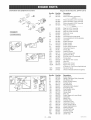
CRAFTSMAN
7000 GENERATOR
18_
614_
919.070070
Briggs
& Stratton
Model
No. 294447=1257=E1
691
_7_8
dP
17
276
"k
REQUIRES
SPECIAL
SEE REPAIR
158
TOOL
iNSTRUCTiON
TO iNSTALL.
MANUAL
22_
34
34
1029_
33 ,
276A
GRAPROIL fi
42
GRAPHOIL
fi
@
1022_
40_
1022_
36
42
40_)@
42
42
REQUIRES
SPECIAL
TOOLS
TO iNSTALL.
SEE REPAIR
iNSTRUCTION
MANUAL.
No.
1
2
3
5
5A
7
8
9
10
11
12
13
15
17
18
20
22
33
34
35
36
4O
42
45
Part No,
692178
808534
805101
808381
808382
806085
807795
807688
690751
806083
806190
805097
94239
690752
808847
805049
692540
807681
807680
692084
682084
805092
807683
262679
MGP670070
Description
Cylinder Assembly
Bushing/Sea! Kit
OiI Sea! (Magneto Side)
Cylinder Head (#1)
Cylinder Head (#2)
Cylinder Head Gasket
Breather Assembly
Breather Gasket
Screw (Breather Assembly)
Breather Tube
Crankcase Gasket
Screw (Cylinder Head)
OiI Drain Plug
Ball Bearing
Crankcase Cover
_No.
192
Oil Sea! (PTO Side)
Screw (Crankcase Cover/Sump)
Exhaust Valve
Intake Valve
Valve Spring (Intake)
Valve Spring (Exhaust)
Valve Retainer
_,ealveKeeper
Valve Tappet
868
276
276A
337
383
439
552
552A
572
616
635
691
718
830
871
1022
1026
1029
1100
30 -- ENG
Part No.
807623
690704
805420
491055
19374
692154
690701
806686
690686
806685
805529
690680
690684
691544
805094
805084
806039
805352
805617
691543
690973
Description
Rocker Arm Adjuster
Sealing Washer
Sealing Washer
Spark Plug
Spark Plug Wrench
O-Ring Sea!
(Crankcase Cover/Sump)
Governor Shaft Bushing
Governor Shaft Bushing
Breather Baffle
Governor Crank
Spark Plug Boot
Governor Shaft Seal
Locating Pin
Stud (Rocker Arm)
Valve Seal
Bushing Guide
Rocker Arm Gasket
Push Rod (Steel)
Push Rod (Aluminum)
(Exhaust Side Only)
Rocker Arm
Rocker Arm Pivot
CRAFTSMAN
7000 GENERATOR
919.670070
Briggs
_No,
16
25
Part No,
692163
807619
26
807807
807809
807811
807620
OWNER'S
MANUAL
46
5O
51
51A
54
122
146
276A
365
522
598
741
812
1019
1023
1023A
1025
1058
690689
274272
Part No,
805700
807919
808257
690718
807720
808177
805541
690723
805547
690719
807722
806652
690720
808249
690727
690726
691510
690725
690718
690721
690724
690722
805557
807723
691516
Description
Intake Gasket
Upper Carburetor Body Assembly
Idle Mixture Kit
Screw (Throttle Valve)
Throttle Shaft
Idle Speed Kit
Carburetor Body Gasket
Float Hinge Pin
Float Needle Valve
Choke Valve
Choke Shaft
Main Jet
Screw (Upper to Lower Body)
Carburetor
Welch Plug
Throttle Valve
Carburetor Float
Carburetor Nozzle
Screw (Choke Valve)
Choke Shaft Bushing
Sealing Washer
Choke Shaft Seal
Throttle Spacer
Carburetor Plug
Limiter Cap
No,
i.....
++°+ -4b
,o+Q#
105
10°
i
117_
,
!3oQ
!27\
No. 294447+1257+E1
807808
807810
807812
690683
807621
807900
807803
691557
807802
805700
805023
690676
690691
94196
805420
690711
491832
807625
805675
805019
808035
691494
690910
27
28
29
I
Model
Description
Crankshaft
Piston Assembly (Standard)
NOTE
Piston Assembly (.010 Oversize)
Piston Assembly (+020 Oversize)
Piston Assembly (+030 Oversize)
Ring Set (Standard)
NOTE
Ring Set (.010 Oversize)
Ring Set (+020 Oversize)
Ring Set (+030 Oversize)
Piston Pin Lock
Piston Pin
Connecting Rod (Standard)
Connecting Rod (,020 Undersize)
Camshaft
Intake Manifold
Intake Gasket
Intake Gasket
Screw (Intake Gasket)
Carburetor Spacer
Timing Key
Sealing Washer
Screw (Carburetor)
Dipstick/Fill Plug
End Play Shim (Crankshaft)
Timing Gear
Nut (Rocker Arm Cover)
Label Kit
Rocker Arm Cover
Rocker Arm Cover
(Cylinder #! Fuel Pump Applications)
Governor Spool
Owner's Manual (Emission Engines)
50
[ 1008
& Stratton
51
91
94
95
97
98
1O2
1O4
1O5
1O8
1O9
117
119
125
127
130
133
142
231
255
276B
633
8O7
955
1091
31 -- ENG
NGP670070
CRAFTSMAN
7000 GENERATOR
919.670070
Briggs
& Stratton
Model
No. 294447-1257-E1
226
520 507_
_
683
578
373@
1!19 _
1054__
No,
188
2O3
2O5
2O6
2O8
2O9
211
212
216
222
226
227
232
234
239
262
278
28O
333
334
359
373
MGP670070
Part
No,
805025
690923
805762
691244
691549
691506
805450
690712
690705
808454
690705
690236
805465
221372
491657
805762
690237
691526
492341
805407
691077
90576
Description
Screw (Control Bracket)
Be!I Crank
Screw (Bell Crank)
Governor Adjusting Nut
Governor Control Rod
Governor Spring
Governor Idle Spring
Throttle Link
Choke Link
Control Bracket
Hand Choke Rod
Governor Control Lever
Governor Link Spring
Control Rod Clip
Oil Pressure Switch
Screw (Rod Bracket)
Washer (Governor Control Lever)
Rod Bracket
Magneto Armature
Screw (Magneto Armature)
Washer (Ground Terminal)
Nut (Ground Terminal)
_No,
432
474
493
501
5O5
5O7
52O
526
555
562
577
578
683
689
729
813
851
878
879
920
1054
1119
32 -- ENG
Part
No,
691509
393295
691177
394890
690238
398525
691084
805448
805448
690239
690795
493792
92278
691272
690586
690635
493880
399916
690757
807829
280275
691552
Description
Spring Cap
AItemator
Mounting Bracket
Regulator
Nut (Governor Control Lever)
Insulator
Ground Terminal
Screw (Regulator)
Screw (Starter Solenoid)
Bolt (Governor Control Lever)
Starter Cable
Wire Assembly
Nut (Starter Solenoid)
Friction Spring
Wire Clip
Clamp
Spark Plug Terminal
Alternator Harness
Carburetor Cover
Starter Solenoid
Cable Tie
Screw (Alternator)
CRAFTSMAN
7000GENERATOR
919.670070
523
Briggs
_
& Stratton
Model
No. 294447-1257-E1
81g_)
1028
62_j/
524_
10
1139 @_"
_
788
_
6oiA
_j
467
445
/
1971_
996
883
833_
_No,
161
163
187
240
287
300
385
387
430
436
437
445
467
523
524
525
565
601
601A
613
628
Part No,
691561
805655
298049
493629
805177
807948
693169
808656
690679
805142
805158
394018
491875
693175
693172
693174
690682
95162
93807
805448
805247
Description
Air Cleaner Base
Air Cleaner Gasket
Fuel Line
Fuel Filter
Screw (Dipstick Tube)
Exhaust Muffler
Screw (Fuel Pump)
Fuel Pump
Bolt (Oil Filter Adapter)
Exhaust Manifold
Screw (Exhaust Manifold)
Air Cleaner Cartridge Filter
Air Cleaner Knob
Dipstick
Dipstick Tube Seal
Dipstick Tube
Stud (Oil Filter Adapter)
Hose Clamp
Hose Clamp
Screw (Exhaust Muffler)
Screw (Fuel Pump Bracket)
_No,
643
Part No,
805631
788
691559
816
690706
819
805025
833
862
692539
692153
863
691513
883
805024
884
918
690898
393815
967
272490
968
971
807862
692537
988
805250
996
691577
1004
690743
1027
1028
492932
808033
1139
806497
33 -- ENG
Description
Air Filter Retainer
Fuel Pump Bracket
Washer (Oil Filter Adapter)
Screw (Muffler Bracket)
Screw (Cleaner Mounting Strap)
Cleaner Mounting Strap
Muffler Bracket
Exhaust Gasket
Muffler Clamp
Vacuum Hose
(Rocker Cover to Impulse Pump)
(Cut to Length)
Pre-Cteaner Filter
Air Cleaner Cover
Screw (Air Cleaner Base)
Oil Adapter Gasket
Carburetor Shield
Air Duct
Oil Filter
Oil Filter Adapter
Washer (Fuel Pump Bracket)
lvlGP670070
CRAFTSMAN
7000
GENERATOR
919.070070
Briggs
& Stratton
Model
No. 294447-1257-E1
308A_
57:
638-
529 _)
_t_ 322
506
732 _
879
732A _
332
58
59
6_P
No,
23
55
56
57
58
59
60
65
308
308A
322
332
455
456
459
506
MGP670070
Part No,
808766
691568
805949
805951
66574
805957
808167
805026
806546
806547
692539
690887
691517
691529
808166
690677
Description
Flywheel (Steel Ring Gear)
Rewind Starter Housing
Starter Pulley
Rewind Starter Spring
Starter Rope (Cut to Length)
Grip Insert
Starter Rope Grip
Screw (Rewind Starter)
Cylinder Head Cover
Cylinder Head Cover
Screw (Cylinder Head Cover)
Nut (Flywheel)
Flywheel Cup
PawI Friction Plate
Ratchet PawI
Screw (Carburetor Cover)
_No,
515
529
573
597
608
638
726
Part No,
691528
690744
690902
690876
808087
691551
727
732
732A
838
865
879
690714
690688
692539
690875
690750
690757
34 -- ENG
Description
Pawl Spring
Grommet
Back Plate
Screw (Pawl Friction Plate)
Rewind Starter
Washer (Cylinder Head Cover)
Ring Gear (Steel)
(Sold in Flywheel Kit Only; See
Ref. 23.)
Starter Drive Cover
Screw (Starter Drive Cover)
Screw (Starter Drive Cover)
Rewind Starter Ring
Air Guide Cover
Carburetor Cover
CRAFTSMAN
7000 GENERATOR
919.670070
Briggs
& Stratton
Model
No. 294447-1257-E1
\
\
797A
\
801
797
@
305A
1124
I
K_No,
304
305
305A
309
310
311
413
510
544
697
797
Part No,
808055
692539
805247
691564
690323
497608
693587
496881
693548
805247
92278
1036 EM{SSIONS
LABEL
Description
Blower Housing
Screw (Blower Housing)
Screw (Blower Housing)
Starter Motor
Bolt (Starter Motor)
Brush Set
Nut (Starter Motor)
Starter Drive
Starter Armature
Screw (Drive Cap)
Nut (Brush Retainer)
I
_305
_No,
797A
801
802
803
1036
1051
1090
1121
1122
Part No,
693167
808777
497607
693547
806687
691124
497605
810056
93410
Description
Nut (Brush Retainer)
Drive Cap
End Cap
Starter Housing
Emissions Label
Retaining Ring
Brush Retainer
Nut (Fuel Pump Bracket)
Screw
(Blower Housing Adapter)
35 -- ENG
NGP670070
CRAFTSMAN
7000 GENERATOR
919.670070
Briggs
358 ENGINE
GASKET
SET
1095 VALVE
GASKET
SET
& Stratton
Model
No. 294447=1257=E1
1022
_No=
3
7
9
12
20
51
51A
94
102
104
105
121
127
142
163
MGP670070
Pa_ No=
805101
806085
807688
806190
805049
805700
805023
808257
805541
690723
805547
807850
690727
690725
805655
Description
OiI Seal (Magneto Side)
Cylinder Head Gasket
Breather Gasket
Crankcase Gasket
Oil Seal (PTO Side)
Intake Gasket
Intake Gasket
Idle Mixture Kit
Carburetor Body Gasket
Float Hinge Pin
Float Needle Valve
Carburetor Overhaul Kit
Welch Plug
Carburetor Nozzle
Air Cleaner Gasket
_No=
255
276A
276B
358
439
Sump)
633
691
807
812
883
988
1022
1091
1095
36 -- ENG
Part No=
690721
805420
690724
808390
692154
Description
Choke Shaft Bushing
Sealing Washer
Sealing Washer
Engine Gasket Set
O-Ring Seal (Crankcase Cover/
690722
690680
805557
805019
805024
805250
806039
691516
808382
Choke Shaft Seal
Governor Shaft Seal
Throttle Spacer
Nut (Rocker Arm Cover)
Exhaust Gasket
OiI Adapter Gasket
Rocker Arm Gasket
Limiter Cap
Valve Gasket Set
37-- ENG
lvlGP
670070
MGP
670070
38-- ENG
39-- ENG
lvlGP
670070
Dear Customer,
In manufacturing this product, many steps have been taken to provide you with the highest quality.
Unfortunately, errors or omissions occasionally occur. In the event that you find a missing or defective part, please contact your nearest Sears store.
SERVICEAND REPAIRPARTS
CALL1o800o665o4455 *
Keep this number
handy should you require
need to order repair parts.
If ordering
a service
call or
parts make sure you have the
name, make and model no. of the merchandise
and number
and the name
of the part you wish to order.
* If calling locally, please use one of the following numbers:
Regina - 566-5124
Toronto - 744-4900
Montreal - 333-5740
Halifax - 454-2444
Kitchener - 894-7590
Ottawa - 738-4440
Vancouver-
420-8211
If you have any suggestions that would help us to improve our assembly/operation
this product, please write them down and mai! it to:
Sears Canada Inc.
222 Jarvis Street
Toronto, Ontario
M5B 2B8
Attention:
Model No.
Buyer Dept: D671
NAME
ADDRESS
POSTAL CODE
PHONE #
COMMENTS
MGP670070
40 -- ENG
instructions, or