1
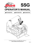
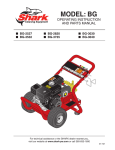
MODEL: BR
OPERATING INSTRUCTION
AND PARTS MANUAL
■ BR-442537
■ BR-404027
■ BR-353237
■ BR-455037E
■ BR-353537
■ BR-343087E
For technical assistance or the SHARK dealer nearest you, call 1-800-771-1881
or visit our website at www.shark-pw.com
97-723
CONTENTS
Important Safety Information ................................................................ 3-4
Component Identification ........................................................................ 5
Assembly Instructions ............................................................................. 6
Operating Instructions ............................................................................. 7
Applying Detergent and General Operating Techniques .......................... 8
Shut Down and Clean-Up ....................................................................... 9
Storage ................................................................................................... 9
Troubleshooting .................................................................................... 10
Preventative Maintenance ..................................................................... 11
Oil Change Record ............................................................................... 11
Exploded View ...................................................................................... 12
Exploded View Parts List ...................................................................... 13
Hose and Spray Gun Assembly ............................................................ 14
Downstream Injector ............................................................................. 14
Warranty
Model Number ______________________________
Serial Number ______________________________
Date of Purchase ___________________________
The model and serial numbers will be found on a decal attached to
the pressure washer. You should record both serial number and
date of purchase and keep in a safe place for future reference.
3
96-718, 97-721, 97-722, 97-723 • REV. 4/04
PRESSURE WASHER
INTRODUCTION
Thank you for purchasing a this pressure washer.
All information in this manual is based on the latest product information available at the time of printing.
Manufacturer reserves the right to make changes at
any time without incurring any obligation.
This machine was designed for maximum use
of 8 hours per day, 5 days per week.
OPERATOR’S MANUAL
Owner/User Responsibility:
The owner and/or user must have an understanding of
the manufacturer’s operating instructions and warnings
before using this pressure washer. Warning information
should be emphasized and understood. If the operator
is not fluent in English, the manufacturer’s instructions
and warnings shall be read to and discussed with the
operator in the operator’s native language by the purchaser/owner, making sure that the operator comprehends its contents.
Owner and/or user must study and maintain for future
reference the manufacturers’ instructions.
The operator must know how to stop the machine quickly
and understand the operation of all controls. Never permit anyone to operate the engine without proper instructions.
This manual should be considered a permanent
part of the machine and should remain with it if
machine is resold.
When ordering parts, please specify model and
serial number.
IMPORTANT SAFETY
INFORMATION
CAUTION: To reduce the risk of
injury, read operating instructions carefully before using.
1. Read the owner's manual thoroughly. Failure to follow instructions could cause malREAD OPERATOR’S
function of machine and result
MANUAL THOROUGHLY
in death, serious bodily injury
PRIOR TO USE.
and/or property damage.
2. All installations must comply with local codes. Contact your electrician, plumber, utility company or the
selling distributor for specific details.
3. This machine has been provided with Warning and
Instruction decals for the safety of the operator. If
these decals are removed or become damaged they
should be replaced. Contact your dealer for replacement decals.
CAUTION
CAUTION: Risk of asphyxiation
— Use this product only in a well
ventilated area.
4. Avoid installing machines in
small areas or near exhaust
fans. Exhaust contains poisonRISK OF
ous carbon monoxide gas; exASPHYXIATION.
USE ONLY IN A WELL
posure may cause loss of conVENTILATED AREA.
sciousness and may lead to
death. It also contains chemicals known, in certain
quantities, to cause cancer, birth defects or other
reproductive harm.
CAUTION
WARNING
WARNING
RISK OF FIRE.
DO NOT ADD FUEL
WHEN OPERATING
MACHINE.
WARNING: Flammable liquids
can create fumes which can ignite causing property damage or
severe injury.
WARNING: Risk of fire — Do not
add fuel when the product is
operating.
WARNING: Risk of explosion —
Do not spray flammable liquids.
5. Do not place machine near flammable objects as
the engine is hot.
6. Allow engine to cool for 2 minutes before refueling.
If any fuel is spilled, make sure the area is dry before testing the spark plug or starting the engine.
(Fire and/or explosion may occur if this is not done.)
When refueling gasoline engines on mobile or portable equipment, make sure to refuel:
a. outdoors;
b. with the engine on the equipment stopped;
c. with no source of ignition within 10 feet of the
dispensing point; and
d. with an allowance made for expansion of the
fuel should the equipment be exposed to a
higher ambient temperature.
In an overfilling or spillage situation, additional precautions are necessary to ensure that the situation
is handled in a safe manner.
WARNING
HIGH PRESSURE
SPRAY CAN PIERCE
SKIN AND TISSUES.
4
96-718, 97-721, 97-722, 97-723 • REV. 4/04
WARNING: High pressure
stream of water that this equipment can produce can pierce
skin and its underlying tissues,
leading to serious injury and
possible amputation.
14. Cleaning area should be provided with adequate
slopes and drainage. This will reduce the possibility of a fall due to slippery surface.
15. The best insurance against an accident is precaution and knowledge of the machine.
16. Manufacturer will not be liable for any changes made
to our standard machines, or any components not
purchased from the manufacturer.
17. Read engine safety instructions provided.
OPERATOR’S MANUAL
WARNING: Keep water spray
away from electrical wiring or fatal electric shock may result.
18. Never run pump dry or leave
spray gun closed longer than
5 minutes.
19.
Do
not allow children to operKEEP WATER SPRAY
AWAY FROM
ate
the pressure washer at
ELECTRICAL WIRING.
any time.
20. Do not allow machine to run unattended.
21. Inlet water supply must be cold and clean fresh
water.
WARNING
PRESSURE WASHER
WARNING: High pressure spray
can cause paint chips or other
particles to become airborne and
fly at high speeds. To avoid personal injury, eye safety devices
must be worn.
PROTECTIVE
7. Protective clothing and foot
EYEWEAR AND
CLOTHING MUST
protection must be worn when
BE WORN.
using this equipment.
8. High pressure developed by these machines will
cause personal injury or equipment damage. Use
caution when operating. Do not direct discharge
stream at people, or severe injury or death will result.
9. Never make adjustments on machine while in
operation.
10. Do not block or tie spray gun in open position.
11. Do not place hands or feet on non-insulated areas of
the pressure washer when starting gasoline engine.
12. When applying detergents, follow the safety rules
on the detergent label.
13. Use detergent from a covered D.O.T. approved container.
WARNING
CAUTION: Spray gun kicks back – Hold with both
hands.
CAUTION: Risk of injury – Disconnect battery
ground terminal before servicing.
5
96-718, 97-721, 97-722, 97-723 • REV. 4/04
PRESSURE WASHER
OPERATOR’S MANUAL
COMPONENT IDENTIFICATION — SMALL MODELS
Nozzle
Wand
Spray Gun
Starter
Grip
Pump
High Pressure
Discharge
Water Inlet
High Pressure
Hose
Pump — Develops high pressure.
Wand — Must be connected to the spray gun.
Starter Grip— Used for starting the engine manually.
High Pressure Hose — Connect one end to water
pump discharge nipple and the other end to spray gun.
Spray Gun — Controls the application of water and
detergent onto cleaning surface with trigger device. Includes safety latch.
Detergent Injector — Allows you to siphon and mix
detergents (not shown).
Note: If trigger on spray gun is released for more
than 2 minutes, water will leak from valve. Warm
water will discharge from pump protector onto floor.
This system prevents internal pump damage.
6
96-718, 97-721, 97-722, 97-723 • REV. 4/04
Nozzle
Wand
OPERATOR’S MANUAL
Spray Gun
PRESSURE WASHER
COMPONENT IDENTIFICATION — LARGE MODELS
Starter
Grip
Pump
Water Inlet
High Pressure
Discharge
High Pressure
Hose
7
96-718, 97-721, 97-722, 97-723 • REV. 4/04
PRESSURE WASHER
OPERATOR’S MANUAL
ASSEMBLY INSTRUCTIONS
Spray
Gun
Pressure
Nozzle
Pressure
Nozzle
Wand
Coupler
Wand
Coupler
Safety
Latch
High Pressure
Hose
Wand
Collar
STEP 1: Attach the high pressure hose to the spray gun using
teflon tape on hose threads.
STEP 2: Pull the spring-loaded
collar of the wand coupler back
to insert your choice of pressure
nozzle.
STEP 3: Release the coupler
collar and push the nozzle
until the collar clicks. Pull the
nozzle to make sure it is
seated properly.
Cold
Water
Source
Dipstick
Discharge
Fitting
Coupler Collar
High Pressure Hose
STEP 4: Remove shipping cap and
install oil dipstick. Check pump oil
level by using dipstick or observe oil
level in oil window (if equipped). Use
30 wt. non detergent oil.
STEP 5: Connect the high pressure
hose to the pump discharge fitting.
Push coupler collar forward until
secure.
Garden
Hose
Pump
Water Inlet
STEP 7: Check inlet filters, remove
debris, then connect garden hose to
pump water inlet. CAUTION: Do not
run the pump without water or
pump damage will result.
8
96-718, 97-721, 97-722, 97-723 • REV. 4/04
Garden
Hose
STEP 6: Connect garden hose to
the cold water source.
PRESSURE WASHER
OPERATING INSTRUCTIONS
Oil Dipstick
Gas
Tank
STEP 2: Fill gas tank with unleaded
gasoline. Do not use leaded gasoline.
OPERATOR’S MANUAL
STEP 1: Check engine oil level. Oil level should be level with the bottom of
the oil filler neck. Be sure the machine is level when checking the oil level.
(Refer to the engine's operating manual included with machine.) We recommend that the oil be changed after the first 5 hours of use, then once
every 50 hours. Note: Improper oil levels will cause low oil sensor to shut
off engine. IMPORTANT! Do not run engine with high or low oil levels
as this will cause engine damage.
Cold
Water
Source
Garden
Hose
STEP 3: Connect garden hose to
the cold water source and turn water on completely. Never use hot
water.
STEP 4: Trigger the spray gun
to eliminate trapped air then wait
for a steady flow of water to
emerge from the spray nozzle.
Choke
Lever
Fuel
Valve
STEP 5: Rotate the fuel shut-off valve to the "On" position. Slide the fuel valve lever to the "ON" position. When
the engine is not in use, leave the fuel valve in the "OFF"
position.
STEP 6: Pull the choke lever out to the "Choke" position (on a warm engine, leave the choke lever in, in the
run position). Push the choke lever to the "Closed" position. To restart a warm engine, leave the choke lever
in the "Open" position.
9
96-718, 97-721, 97-722, 97-723 • REV. 4/04
PRESSURE WASHER
OPERATOR’S MANUAL
OPERATING INSTRUCTIONS (CON'T)
On-Off
Switch
STEP 7: Turn the engine switch to "ON" position.
STEP 8: Pull the starter grip. If the engine fails to start
after 2 pulls, squeeze the trigger gun to release pressure and repeat step. Return starter gently. After the
engine warms up enough to run smoothly, move choke
to run position and throttle to fast position.
CAUTION: Small engines may kick back. Do not
hold pull starter grip tightly in hand.
NOZZLES
Safety
Latch
WARNING! Never replace
nozzles without engaging the
safety latch on the spray gun
trigger.
The five color-coded quick connect
nozzles provide a wide array of spray
widths from 0° to 45° and are easily
accessible when placed in the convenient rubber nozzle holder, which is
provided on the front of the machine.
NOTE: For a more gentle rinse, select
the white 40° or green 25° nozzle. To
scour the surface, select the yellow 15°
or red 0° nozzle. To apply detergent
select the black nozzle.
10
96-718, 97-721, 97-722, 97-723 • REV. 4/04
WARNING: Some detergents
may be harmful if inhaled or ingested, causing severe nausea,
fainting or poisoning. The harmful elements may cause property damage or severe injury.
WARNING
THERMAL PUMP
PROTECTION
If you run the engine on your pressure washer for 3-5
minutes without pressing the trigger on the spray gun,
circulating water in the pump can reach high temperatures. When the water reaches this temperature, the
pump protector engages and cools the pump by discharging the warm water onto the ground. This thermal
device prevents internal damage to the pump.
CLEANING TIPS
Discharge
Nipple
Detergent
Injector
Quick
Coupler
High
Pressure
Hose
Soap Nozzle
Filter
STEP 2: Use detergent designed
specifically for pressure washers.
Household detergents could damage the pump. Prepare detergent
solution as required by the manufacturer. Fill a container with pressure washer detergent. Place the
filter end of detergent suction tube
into the detergent container.
STEP 3: With safety latch on spray gun engaged, secure black detergent nozzle into quick coupler.
NOTE: Detergent cannot be applied using red, yellow,
green or white nozzles.
STEP 4: With the engine running,
pull trigger to operate machine.
Liquid detergent is drawn into the
machine and mixed with water.
Apply detergent to work area. Do
not allow detergent to dry on surface.
IMPORTANT: You must flush the detergent injection system after each use by placing the suction
tubeinto a bucket of clean water, then run the pressure washer in low pressure for 1-2 minutes.
Pre-rinse cleaning surface with fresh water. Place detergent
suction tube directly into cleaning solution and apply to surface at low pressure (for best results, limit your work area to
sections approximately 6 feet square and always apply detergent from bottom to top). Allow detergent to remain on
surface 1-3 minutes. Do not allow detergent to dry on surface. If surface appears to be drying, simply wet down surface with fresh water. If needed, use brush to remove stubborn dirt. Rinse at high pressure from top to bottom in an
even sweeping motion keeping the spray nozzle approximately 1 foot from cleaning surface. Use overlapping strokes
as you clean and rinse any surface. For best surface cleaning action spray at a slight angle.
OPERATOR’S MANUAL
STEP 1: Connect detergent injector t discharge nipple
on machine. Connect high pressure hose to injector
with quick coupler. (Check to make sure locking coupler sleeves are in proper position before applying water pressure).
PRESSURE WASHER
APPLYING DETERGENT AND
GENERAL CLEANING
TECHNIQUES
Recommendations:
• Before cleaning any surface, an inconspicuous
area should be cleaned to test spray pattern and
distance for maximum cleaning results.
• If painted surfaces are peeling or chipping, use
extreme caution as pressure washer may remove
the loose paint from the surface.
• Keep the spray nozzle a safe distance from the
surface you plan to clean. High pressure wash a
small area, then check the surface for damage. If
no damage is found, continue to pressure washing.
CAUTION - Never use:
• Bleach, chlorine products and other corrosive
chemicals
• Liquids containing solvents (i.e., paint thinners,
gasoline, oils)
• Tri-sodium phosphate products
• Ammonia products
• Acid-based products
These chemicals will harm the machine and will damage the surface being cleaned.
RINSING
It will take a few seconds for the detergent to clear. Apply
safety latch to spray gun. Remove black soap nozzle
from the quick coupler. Select and install the desired
high pressure nozzle. NOTE: You can also stop detergent from flowing by simply removing detergent siphon
tube from bottle.
96-718, 97-721, 97-722, 97-723 • REV. 4/04
11
PRESSURE WASHER
OPERATOR’S MANUAL
SHUTTING DOWN AND CLEAN-UP
On-Off
Switch
STEP 1: Remove detergent suction
tube from container and insert into
one gallon of fresh water. Slide nozzle
forward for low pressure or to connect
black detergent nozzle. Pull trigger on
spray gun and siphon water for one
minute.
STEP 2: Turn engine switch to "OFF"
position.
STEP 3: Turn off water
supply.
High
Pressure
Outlet
Safety
Latch
Water
Inlet
STEP 4: Press trigger to release water
pressure.
STEP 5: Disconnect the garden
hose from the water inlet on the
machine.
STEP 6: Disconnect the high
pressure hose from high pressure outlet.
STEP 7: Engage
the spray gun safety
lock.
STORAGE
CAUTION: Always store your pressure washer in a
location where the temperature will not fall below
32°F (0°C). The pump in this machine is susceptible
to permanent damage if frozen. FREEZE DAMAGE
IS NOT COVERED BY WARRANTY.
1. Stop the pressure washer, squeeze spray gun trigger to release pressure.
2. Detach water supply hose and high pressure hose.
3. Turn on the machine for a few seconds, until remaining water exits. Turn engine off immediately.
4. Drain the gas and oil from the engine.
5. Do not allow high pressure hose to become kinked.
6. Store the machine and accessories in a room which
does not reach freezing temperatures.
12
CAUTION: Failure to follow the above directions will
result in damage to your pressure washer.
When the pressure washer is not being operated or is being
stored for more than one month, follow these instructions:
1. Replenish engine oil to upper level.
2. Drain gasoline from fuel tank, fuel line, fuel valve
and carburetor.
3. Pour about one teaspoon of engine oil through the
spark plug hole, pull the starter grip several times
and replace the plug. Then pull the starter grip slowly
until you feel increased pressure which indicates
the piston is on its compression stroke and leave it
in that position. This closes both the intake and exhaust valves to prevent rusting of cylinder.
4. Cover the pressure washer and store in a clean, dry
place that is well ventilated away from open flame or
sparks. NOTE: The use of a fuel additive, such as
STA-BIL®, or an equivalent, will minimize the formulation of fuel deposits during shortage. Such additives may be added to the gasoline in the fuel tank of
the engine, or to the gasolinee in a storage container.
After Extended Storage
CAUTION: Prior to restarting, thaw out any
possible ice from pressure washer hoses,
spray gun or wand.
Engine Maintenance
During the winter months, rare atmosheric conditions may
develop which will cause an icing condition in the carburetor. If this develops, the engine may run rough, lose
power and may stall. This temporary condition can be
overcome by deflecting some of the hot air from the engine over the carburetor area. NOTE: Refer to the engine manufacturer's manual for service and maintenance
of the engine.
96-718, 97-721, 97-722, 97-723 • REV. 4/04
PROBLEM
POSSIBLE CAUSE
SOLUTION
LOW OPERATING
PRESSURE
Insufficient water supply. Closed
faucet. Inlet hose kinked
Use larger garden hose; clean inlet water
screen. Open faucet.
Clogged inlet hose strainer
Check plumbing system for leaks.
Retape leaks with teflon tape.
Faulty or misadjusted unloader
valve
Adjust unloader for proper pressure.
Install repair kit when needed. Call
technical support.
Worn packing in pump
Call technical support.
Machine has been stored in
freezing temperatures
Thaw out machine completely, including
hose, spray gun and wand.
Slow engine RPM
Call technical support.
Worn or dirty pump valves
Call technical support.
Nozzle is obstructed
Use nozzle wire in accessory kit.
Pump sucking air, inlet hose
leaking
Check all pump lines and connections.
Nozzle worn
Replace nozzle.
Unloader valve worn
Replace unloader valve.
Low oil shutdown
Fill engine with oil.
Out of gas
Fill fuel tank.
Water in gasoline
Drain gas tank; fill with clean fuel.
Nozzle partially blocked
Clean nozzle.
Excessive pressure from high
engine RPM
Adjust engine throttle to lower RPM.
WATER OR OIL
LEAKING FROM
BOTTOM OF PUMP
A small amount of leaking is
normal
If excessive leaking occurs, call technical
support.
PRESENCE OF
WATER
IN PUMP OIL
Water sprayed at machine
Change oil. Direct spray away from
machine.
High humidity in air
Check and change oil twice as often.
Piston packing worn. Oil seal
worn.
Call technical support.
FLUCTUATING
PRESSURE
PRESSURE LOW
AFTER PERIOD OF
NORMAL USE
ENGINE WILL NOT
START OR STOPS
WHILE OPERATING
ENGINE IS
OVERLOADED
PRESSURE WASHER Troubleshooting Guide
TROUBLESHOOTING
13
96-718, 97-721, 97-722, 97-723 • REV. 4/04
PRESSURE WASHER
OPERATOR’S MANUAL
TROUBLESHOOTING
PROBLEM
POSSIBLE CAUSE
SOLUTION
ENGINE OPERATES
FOR 15 MIN. THEN
STOPS
Not enough gas or engine oil
Fill tank with gas. Check oil level.
Vapor lock developed by heat of
day
Keep gas tank full to avoid vapor locking.
Obstruction in fuel filter
Clean or replace fuel filter.
ENGINE LACKS
POWER
Dirty air filter
Replace air filter.
ENGINE FALTERS
Choke is opened too soon
Move choke to halfway position until
engine runs smoothly.
WATER DRIPPING
FROM
UNDER PUMP
Piston packing worn
Call technical support.
O-Ring plunger retainer worn
Call technical support.
Cracked piston
Call technical support.
OIL DRIPPING
Oil seal worn or damaged
Call technical support.
WATER LEAKING
FROM PUMP
PROTECTOR
Spray gun closed with machine
running 5 minutes or longer
Open spray gun or turn off machine.
Excess water supply pressure
Place a pressure regulator at end of 50'
garden hose.
NO DETERGENT
Detergent suction tube not
properly connected to machine
Check connection.
Detergent is too thick
Dilute detergent. For best results, use
Rhino detergent.
Detergent filter valve is at lowest
setting
Set detergent filter valve to a higher
setting.
Filter on detergent suction tube
is clogged
Run warm water through filter to remove
debris.
Damaged or clogged detergent
suction tube
Remove obstruction or replace detergent
suction tube.
A high pressure nozzle is
attached.
Replace with black detergent nozzle.
Discharge nozzle is obstructed
Blow out or remove debris with fine
needle.
GARDEN HOSE
CONNECTION LEAKS
Loose fittings
Tighten fittings.
Missing/worn rubber washer
Insert new washer.
SPRAY WAND LEAKS
Spray wand not properly
attached
Slide the spray wand into the gun. Turn
the wand collar clockwise onto the spray
gun threads until tight.
Broken o-ring
Call customer service and order an oring.
Pump is sucking air
Check that hoses and fittings are air
tight. Turn off machine and purge pump
by squeezing trigger gun until a steady
flow of water emerges through nozzle.
PUMP IS NOISY
14
96-718, 97-721, 97-722, 97-723 • REV. 4/04
This pressure washer was produced with the best available materials and quality craftsmanship. However, you
as the owner have certain responsibilities for the correct care of the equipment. Attention to regular preventative
maintenance procedures will assist in preserving the performance of your equipment. Contact your dealer for
maintenance. Regular preventative maintenance will add many hours to the life of your pressure washer. Perform maintenance more often under severe conditions.
Inspect
Daily inspect the oil level
Change
After first 50 hours, then every 500 hours or annually
Pump Oil
Every 6 months
Replace quick connects
Annually
Clean water screen/filter
Weekly
Replace HP hose
Annually if there is any sign of wear
Grease motor
Every 10,000 hours
OPERATOR’S MANUAL
Replace high pressure nozzle
PRESSURE WASHER
PREVENTATIVE MAINTENANCE
OIL CHANGE RECORD
Check pump oil and engine oil level before first use of your new pressure washer.
Date Oil Changed
Month/Day/Year
Estimated Operating
Hours Since Last
Oil Change
Date Oil Changed
Month/Day/Year
Estimated Operating
Hours Since Last
Oil Change
15
96-718, 97-721, 97-722, 97-723 • REV. 4/04
PRESSURE WASHER
EXPLODED VIEW - LARGE
4
57
55
37
73
34
79
38 35
36
5
2
56
57
OPERATOR’S MANUAL
31
All Models
Except
4040
26
76
73
57
52
32
28
39
75
60
16
40 20
23
1
78
27
59
33
18
16
3
13
21
12
18
45
65
18
77
23
19
14
15
9
33
8
22
8, 9
Models 404027,
404029
50
61
Models
404022,
404029
53
22
7
54
59
60
53
11
30
80
17
48
6
74
74
49
24
49
47, 62
49
74
69
48
51
43,44
74
10, 41
68
74
29
48
48
46
81
48
60
47
64
48
59
42
74
71
74
29
72
51
70
25
48
58
70
67 66
16
96-718, 97-721, 97-722, 97-723 • REV. 4/04
59, 60, 61
ITEM PART NO. DESCRIPTION
QTY
1
10-02011
Label, This Tank For Gas Only 1
2
10-02025A
Label, “Hot/Caliente” w/Arrows 1
3
10-02029
Label, Danger Cool Engine
1
10-08028
Tag, Pump Plug/Dipstick
1
10-9999
Label, Clear Lexan, 2-1/4" x
4-1/2"
1
Label, Warning Pictoral (Lexan)1
11-013
▲ Label, Logo, Belt Guard
(404027, 455037E)
▲ Label, Logo, Belt Guard
(405037E, 455037E)
▲ Label, Logo, Belt Guard
(455034E)
▲ Label, Logo, Belt Guard
(404039, 405039E, 455039E)
1
11-3006
1
1
11-0316
Label, Instructions
1
7
10-03008
Label, Nozzle Identification
1
8
2-0051
Nipple, 1/2” JIC, 3/8” Pipe
1
9
2-0079
Swivel, 1/2" JIC Fem,
3/8" Male
1
11
2-010061
2-0103
Bushing, Rubber, Nitrile (405039E,
455039E, 455034E, 405037E,
455037E)
1
Grommet, Rubber, Nozzle
Holder
2-2007
2-30082
2-300816
25
2-9016
Clamp, Round, 0.56 I.D. (405039E,
455039E, 455034E, 405037E,
455037E)
1
26
4-02047914
Hose, 3/8" x 14", 2 Wire,
Pressure Loop
4-02100000
Hose, 1/4", Push-On, Fuel Line
(405039E, 455039E, 455034E,
405037E, 455037E)
4.75 ft.
28
4-02110000
Hose, 1/2", Push-On
29
4-0307
Wheel & Tire Cmpl, 6"
30
4-12803500
Nozzle, SACQMEG, 0003.5, Red
(405039E, 405037E)
1
Nozzle, SAQCMEG 1503.5, Yellow
(405039E, 405037E)
1
Nozzle, SAQCMEG, 2503.5,
Green (405039E, 405037E) 1
Nozzle, SAQCMEG 4003.5, White
(405039E, 405037E)
1
Nozzle, SAQCMEG 0004, Red
(404029, 404027, 455039E,
455034E, 455037E)
1
Nozzle, SAQCMEG 1504, Yellow
(404029, 404027, 455039E,
455034E, 455037E)
1
Nozzle, SAQCMEG 2504, Green
404029, 404027, 455039E,
455034E, 455037E)
1
Nozzle, SAQCMEG 4004, White
(404029, 404027, 455039E,
455034E, 455037E)
1
Nozzle COMPL, QCEM-6540,
Brass 404029, 404027, 455039E,
455034E, 455037E)
1
4-12803515
5
13
2-01167
Cap, Fuel Tank, Plastic (405039E,
455039E, 455034E, 405037E,
455037E)
1
4-12804000
4-12803525
4-12803540
14
2-0117
Battery, Box (405039E, 455039E,
455034E, 405037E, 455037E) 1
4-12804015
15
2-011700
Plate, Battery Box, Small, Polypro
(405039E, 455039E, 455034E,
405037E, 455037E)
1
4-12804025
2-00510
1
2-0155
Fastener, Ratchet, Black Nylon2
18
2-1062
2-1060
Elbow, 1/2" JIC x 1/2", 90°
Elbow, 1/2” JIC x 3/8”, 90°
(404027, 404029)
19
20
21
2-10942
2-1105
2-1923
4-12804040
1
17
1
27
Tank, Encore 5 Gal. Tank
(405039E, 455039E, 455034E,
405037E, 455037E)
1
Nipple 1/2" JIC x 3/8" Male
(4040)
Nipple, 1/2" JIC x 3/8" Fem
(4050, 4550)
Pump Protector, 1/2" PTP
(405039E, 455039E, 455034E,
405037E, 455037E)
1
Pump Protector, 3/8" (404027,
(404029)
1
Clamp, Snap-In Wire (405039E,
455039E, 455034E, 405037E,
455037E)
2
2-011507
2-0051
QTY
2-90151
12
16
DESCRIPTION
Nipple, 3/8" Fem, 11,000 PSI”
(405039E, 455039E, 455034E,
405037E, 455037E)
1
Nipple, 3/8" x 3/8" NPT ST Male
(404027, 404029)
1
24
1
6
10
2-20022
4-16540
2
15 ft.
4
31
Engine, See Specifications, Pages 22-23
32
Pump, See Specifications, Pages 22-23
1
33
Unloader, See Specifications, Pages 22-23
Swivel, 1/2" JIC Fem, Push-On2
34
Engine Pulley, See Specifications, Pages 22-23
Strainer, 1/2" PA, Inline Plastic 1
35
Pump Pulley, See Specifications, Pages 22-23
36
Pump Bushing, See Specifications, Pages 22-23
37
Engine Bushing, See Specifications, Pages 22-23
38
Belts, See Specifications, Pages 22-23
Swivel, 1/2"MP x 3/4" GHF
w/Strainer
1
OPERATOR’S MANUAL
11-0101
5
10-0313
22
23
4
11-014
ITEM PART NO.
PRESSURE WASHER
EXPLODED VIEW PARTS LIST- LARGE
17
96-718, 97-721, 97-722, 97-723 • REV. 4/04
PRESSURE WASHER
OPERATOR’S MANUAL
EXPLODED VIEW PARTS LIST- LARGE
ITEM PART NO.
39
40
6-05109
6-051092
QTY
ITEM PART NO.
61
62
Cable, Battery, 36" Black, 4 Gauge
(405039E, 455039E, 455034E,
405037E, 455037E)
1
63
41
7-80320
Valve, Shut-Off, w/o Filter
42
90-1007
Bolt, 5/16" x 1", NC HH (405039E,
455039E, 455034E, 405037E,
455037E)
4
43
90-1010
Bolt, 5/16" x 1-3/4", NC HH
(404027, 404029)
4
1
64
90-100543
DESCRIPTION
QTY
Screw, 5/16"-18 x 3/4" M PH
TRH
4
90-4011
Washer, 5/16" Star, External
4
90-400910
▲ Washer, 7/16" Lock-Split
Ring
4
Grip, 1" Square Handle
2
1
2-01103
65
2-10323
Tee, 1/2", Branch Male
66
95-0710482
Bracket, Brake Pad, Red
(BD, BR, BC)
1
Bracket, Brake Pad, Black (MP)1
95-07164828
67
95-07164829
95-07104829
Linkage, Brake, Black (MP)
1
Linkage, Brake, Red (BC, BD,
MP)
1
44
90-1020
Bolt, 3/8" x 2", NC HH
4
45
90-1020
Bolt, 3/8" x 2" GR 5 Zinc
2
68
90-3096
Washer, 1/2" Flat
46
90-102746
Bolt, 1/2" x 5" NC HH Tap
1
69
95-07162065
47
90-18012
90-19925
Screw, 1/4" x 5/8", Phil PH MS 4
Screw, M6 x 20mm, BH SOC
Black
4
Handle, Break, CW Cage,
Red
Handle, Break, CW Cage,
Black
48
90-20041
Collar, 5/8" Bore Shaft
8
70
90-100472
49
90-40181
Washer , Nylon Spacer, 0.656 x
1.25 x 0.65 THK
4
Bolt, Carriage, Zinc, 1/4"-20 x 1.0
PLT
4
71
2-9040
Clamp, Hose, .46-.54 ST
(405039E, 455039E, 455034E,
405037E, 455037E)
2
50
95-07162066
1
1
1
95-07101216/B Block, Unloader, 3/8" x 3/8"
Brass
1
51
95-07393125
Axle, 5/8" x 31.25"
2
72
90-4000
Washer, 1/4" Flat, SAE
52
95-07104028
Guard, Belt, Rear Steel
1
73
90-40001
53
95-07162047
Assy, Weld, Battery Brkt, CW
Cage, Red (405039E, 455039E,
405037E, 455037E)
1
Assy, Weld, Battery Brkt, CW
Cage, Black (455034E)
1
Holder, Nozzle (404027
404029)
1
Washer, 1/4" FLAT, SAE, Black,
Zinc
11
74
90-4005
Washer, 5/8" Flat
75
2-3409
Dusk, Rupture Assy, 7000PSI
(405039E, 455039E, 455034E,
405037E, 455037E)
1
76
2-00271
Elbow, 3/8" x 1/2" Street, Steel
(405039E, 455039E, 455034E,
405037E, 455037E)
1
1
77
2-0006
Nipple, 3/8" Hex Steel
1
1
78
2-0053
Elbow, 1/2" JIC, 3/8", 90°
1
79
77-VHRM4
Muffler, Honda, GX620/670 Right
(All Models Except 404029,
404027)
1
76-807964
▲ Muffler, Exhaust, Briggs 16HP
(404029, 404027)
1
95-07101149 ▲ Guard, Muffler, Briggs 16HP
(404029, 404027)
1
95-071011491 ▲ Brace, Muffler Guard (404029,
404027)
2
80
10-9999
Clear Lexan
1
81
10-08017
Label, Intended For Outdoor
Use
1
95-07162047
95-07162081
54
95-07162054
95-07162055
Assy, Weld, Cage, CW Red
(BD, BG, BR)
Assy. Weld, Cage, CW Black
(MP)
55
95-07162046
Guard, Belt, Front, CW Cage,
Large
1
56
95-07162071
95-07104039
Assy, Weld, Slider, CW Cage,
Red (All Except 404027,
445034E)
1
Assy, Weld, Slider, CW Cage,
Black (455034E)
1
Slider (404027)
1
90-1995
90-19980
Screw, 1/4" x 1/2" BH SOC CS 7
Screw, 1/4" x 1", BH SOC CS 2
58
90-2000
Nut, 1/4" ESNA, NC
4
59
90-4001
Washer, 5/16" FLAT, SAE
(404027, 404029)
Washer, 3/8"
12
10
95-07162072
57
90-4002
60
18
DESCRIPTION
Cable, Battery, 32" Red, 4 Ga.
(405039E, 455039E,455034E,
405037E, 455037E)
1
90-2001
90-2002
Nut, 5/16" ESNA, NC (404027,
404029)
4
Nut, 3/8" ESNA
6
96-718, 97-721, 97-722, 97-723 • REV. 4/04
▲ Not Shown
12
8
5
34
41
7
35
1
32
15
29
33
36
26
42
45
56
25
37
56
30
21
21
9
19
OPERATOR’S MANUAL
2
41
37
51
PRESSURE WASHER
EXPLODED VIEW - SMALL
18
48
38
22
17
10
11
40
20
24
31
9
50
23
53
14
16
4
43
3
28
12
49
6
44
49
43
43
55
45
27
8
37
43
54
39
13
52
27
47
38
19
96-718, 97-721, 97-722, 97-723 • REV. 4/04
PRESSURE WASHER
OPERATOR’S MANUAL
20
EXPLODED VIEW PARTS LIST- SMALL
ITEM PART NO. DESCRIPTION
QTY
1
10-02025A
Label, "Hot/Caliente" w/Arrows
Warning
1
2
10-02029
Label, Danger Cool Engine
3
10-08017
10-08028
Label, Intended For Outdoor Use 1
▲ Tag, Pump Plug/Dipstick
1
4
10-9999
Label, Clear Lexan,
2-1/4" x 4-1/2"
5
11-01011
Label, Warning, Pictoral, Small 1
6
11-0316
Label, Instructions, BC, BR
7
10-0623
Label, Belt Guard, MP (442534,
353234, 373534)
Label, Belt Guard, BC (353237,
373537)
Label, Belt Guard, BD (442539,
353239, 373539)
Label, Belt Guard, BR (442537,
353237, 373537)
11-3199
11-32289
11-3229
8
10-03008
Label, Nozzle Identification
ITEM PART NO. DESCRIPTION
QTY
28
4-12804040 Nozzle, SAQCMEG 4004, White
(353239, 373539, 353237,
373534, 353237, 373537)
1
4-12805500 Nozzle, SAQCMEG 0005.5, Red
(442539, 442537)
1
4-12805515 Nozzle, SAQCMEG 1505.5, Yellow
(442539, 442537)
1
4-12805525 Nozzle, SAQCMEG 2505.5, Green
(442539, 442537)
1
4-12805540 Nozzle, SAQCMEG 4005.5, White
(442539, 442537)
1
29
Engine, See Specifications, Pages 22-23
30
Pump, See Specifications, Pages 22-23
31
Unloader, See Specifications, Pages 22-23
32
Engine Pulley, See Specifications, Pages 22-23
33
Pump Pulley, See Specifications, Pages 22-23
1
34
Engine Bushing, See Specifications, Pages 22-23
1
35
Pump Bushing, See Specifications, Pages 22-23
1
1
1
1
1
1
9
2-0051
Nipple, 1/2" JIC, 3/8" Pipe
2
36
Belt, See Specifications, Pages 22-23
10
2-0053
Elbow, 1/2" JIC, 3/8", 90°
1
37
90-1020
Bolt, 3/8" x 2" NCHH
4
11
2-0079
Swivel, 1/2" JIC Fem, 3/8" Male 1
38
90-1017
Bolt, 3/8" x 1-1/4", NC HH
6
12
2-0103
Grommet, Rubber, Nozzle
Holder
39
90-102751
Bolt, 1/2" x 3-1/2", NC HH
1
5
40
90-10343
Bolt, 10mm x 20mm, HH
4
41
90-19710
Screw, 1/4" x 3/4" HH NC,
Whiz Loc
3
13
2-01041
Pad, Soft Rubber, 50 Duro
2
14
2-01103
Grip, 1" Square, Handle
2
15
2-0117200
Belt Guard, CW
1
42
90-2002
Nut, 3/8" ESNA, NC
4
16
2-0155
Fastener, Ratchet, Black Nylon 2
43
90-20041
Collar, 5/8" Bore Shaft 3010
4
17
2-10323
Elbow, 1/2" Street, Brass
1
44
90-3096
Washer, 1/2" Flat
1
18
2-1060
Elbow, 1/2" JIC x 3/8", 90°
1
45
90-4002
Washer, 3/8" Flat, SAE
8
19
2-1061
Elbow, 1/2" JIC x 1/4", 90°
1
46
90-4002
Washer, 3/8" SAE, Flat
2
20
2-10942
Swivel, 1/2" MP x 3/4" GHF
w/Strainer
47
90-40125
Washer, 3/8" x 1"
2
1
48
90-400910
Washer, 7/16", Lock Split Ring 4
49
90-40181
Washer, Nylon Spacer, 0.656" x
1.25" x 0.65" Thick
2
50
95-07101216/B Block, Unloader, 3/8" x 3/8"
Brass
21
2-1105
Swivel, 1/2" JIC Fem, Push-On 2
22
2-1923
Strainer, 1/2" PA, Inline Plastic 1
23
2-2007
Nipple, 3/8" x 3/8" NPT ST
Male
1
Pump Protector, 3/8" PTP
1
24
2-300816
25
4-02047720 Hose, 3/8" x 20", 2 Wire,
Pressure Loop
51
1
26
4-02110000 Hose, 1/2", Push-On
1.25 ft.
27
4-0307
28
4-12804000 Nozzle, SAQCMEG 0004, Red
(353239, 373539, 353237,
373534, 353237, 373537)
1
4-12804015 Nozzle, SAQCMEG 1504, Yellow
(353239, 373539, 353237,
373534, 353237, 373537)
1
4-12804025 Nozzle, SAQCMEG 2504, Green
(353239, 373539, 353237,
373534, 353237, 373537)
1
Wheel & Tire Assy, 6" Steel Rim
w/Tube
2
1
95-07104001 Slider, Pump/Belt Guard Mount,
Red (BC, BD, BR)
1
95-07104033 Slider, Pump/Belt Guard Mount,
Black (MP)
1
52
95-07104723 Axle, 5/8" x 27.80 L
53
95-07162004 Assy, Weld, CW Cage, Small
Red (BC, BD, BR)
95-07162005 Assy, Weld, CW Cage, Small
Black (MP)
1
1
1
54
90-2002
Nut, 3/8" ESNA, NC
2
55
90-4002
Washer, 3/8"
2
56
90-4001
Washer, 5/16"
4
96-718, 97-721, 97-722, 97-723 • REV. 4/04
PRESSURE WASHER
HOSE & SPRAY GUN ASSEMBLY
1, 2
1, 2
4
9
3
OPERATOR’S MANUAL
8
6
10
7
5
7
HOSE & SPRAY GUN ASSEMBLY PARTS LIST
ITEM PART NO. DESCRIPTION
1
2
4-0110331
Wand, Side Grip w/Couplers 47.5"
(442539, 353239, 373539, 404039,
343089E)
1
4-012192
Spray Gun w/Wand (5000 PSI),
w/Coupler (405039E, 455039E,
455034E, 405037E, 455037E) 1
4-011143A Wand, SS V.P. Wand, (AL 344)
w/Coupler, w/Soap Nozzle (353234,
373534)
1
4-0111341A Wand, V.P. w/Coupler & Nozzle,
X-Series (353237, 373537,
4044027, 343087E)
1
4-012402
4-01246
3
QTY
Spray Gun Assy, w/Nipple (442539,
353239, 373539, 404039,
343089E)
1
Spray Gun, Shut-Off, AP 1000
(353234, 373534, 442537, 353237,
373537, 404027, 343087E)
1
4-02033450C Hose, 3/8" x 50 ft., 1 Wire, TUFFSkin, w/Coupler (442539)
1
4-02083450C Hose, 3/8" x 50 ft., 1 Wire, 4000PSI,
TUFF-Flex, w/Coupler(353239,
373539, 404029, 353234, 373534)1
4-02043450F Hose, 3/8" x 50 ft., 2 Wire, TUFFSkin, w/5800 PSI Coupler (405039E,
455039E, 455034E, 405037E,
455037E)
1
4-020650C Hose, 3/8" x 50", 1 Wire, Pressure
Flex, w/Coupler (34389E,
BC-343087E)
1
ITEM PART NO. DESCRIPTION
3
4-020750C
4
3-12021
Hose, 3/8" x 50 ft., 2 Wire, Pressure
Flex, w/Coupler (BC-353237,
BC-373537)
1
4-02093450BC Hose, 3/8" x 50 ft., 1 Wire
Blue, w/Coupler (BR-442537,
BR-353237, BR-343087E)
1
4-02073450RC Hose, 3/8" x 50 ft., 2 Wire Blue,
w/Coupler (BR-373537,
BR-404027)
1
3-1208
5
QTY
2-1904
Injector, Detergent, Non-Adj, 3-5
GPM, 0.083
1
Injector, SS, Non-Adj,
2.0-4.0GPM, 5500PSI
1
Strainer, Plastic, 1/4" Hose
Barb
1
6
4-02080000 Tube, 1/4" x 1/2", Clear Vinyl
6 ft.
7
2-9040
Clamp, Hose, .46-.54 ST
8
2-20021
Coupler, 3/8" Female, 11,000 PSI,
Snap-Tite
1
9
2-20022
Nipple, 3/8" Fem, 11,000 PSI
10
4-011184
Detergent Injector Assy, 3-5 GPM,
0.83" (442539, 353239, 373539,
404039, 343089E, 353234, 373534,
353237, 373537, 343037E,
404027)
1
4-011186
Downstream Injector Assy, 5000 PSI
(405039E,455039E, 455034E,
405037E, 455037E)
1
2
1
21
96-718, 97-721, 97-722, 97-723 • REV. 4/04
PRESSURE WASHER
OPERATOR’S MANUAL
SPECIFICATIONS
Machine
Model
442539
353239
373539
404029
405039E
455039E
343089E
Engine
Pulley
5-40503201
5-40503201
5-40503201
5-40503601
5-407034
5-407034
5-40504001
Pulley
Desc.
2BK32H
2BK32H
2BK32H
2BK36H
3TB34
3TB34
2BK40H
Engine
Bushing #
5-511100
5-511100
5-511100
5-511100
5-531112
5-531113
5-511100
Bushing
Desc.
Hx1"
Hx1"
Hx1"
Hx1"
P2x1"
P2x1-1/8"
Hx1"
Pump
Pulley
5-40508001
5-40509001
5-40509001
5-40509001
5-41009001
5-41008001
5-40508001
Pump
Desc.
2BK80H
2BK90H
2BK90H
2BK90H
3BK90H
3BK80H
2BK80H
Pump
Bushing #
5-512024
5-512024
5-512024
5-512025
5-512025
5-512025
5-512022
Bushing
Desc.
24mm
24mm
24mm
25mm
25mm
25mm
22mm
353234
5-40503201
373534
5-40503201
455034E 5-407034
2BK32H
2BK32H
3TB34
5-511100
5-511100
5-531113
Hx1"
Hx1"
P2x1-1/8"
5-40509001
5-40509001
5-41008001
2BK90H
2BK90H
3BK80H
5-512025
5-512025
5-512025
25mm
25mm
25mm
353237
373537
405037E
455037E
442537
404027
343087E
2BK32H
2BK32H
3TB34
3TB34
2BK32K
2BK36H
2BK32H
5-511100
5-511100
5-531112
5-531113
5-511100
5-511100
5-511100
Hx1"
Hx1"
P2x1"
P2x1-1/8"
Hx1"
Hx1"
Hx1"
5-40509001
5-40509001
5-41009001
5-41008001
5-40508001
5-40508001
5-40509001
2BK90H
2BK90H
3BK90H
3BK80H
2BK80H
2BK80H
2BK90H
5-512024
5-512024
5-512025
5-512025
5-512024
5-512026
5-512024
24mm
24mm
25mm
25mm
24mm
30mm
24mm
5-40503201
5-40503201
5-407034
5-407034
5-40503201
5-40503601
5-40503201
22
96-718, 97-721, 97-722, 97-723 • REV. 4/04
Belt
(QTY)
5-604037
5-604039
5-604039
5-604041
5-604042
5-604042
5-604042
(2)
(2)
(2)
(2)
(3)
(3)
(2)
Pump
Part No.
5-1807
5-1220
5-1220
5-1808
5-1238
5-1238
5-1803
Unloader
Part No.
5-32080
5-32080
5-32080
5-32080
5-3014
5-3014
5-32080
Engine
Part No.
5-0105
5-0105
5-010721
5-0306
5-01093
5-01094
5-0413
353234
373534
455034E
5-604039 (2)
5-604039 (2)
5-604042 (3)
5-1724
5-1724
5-1738
5-32080
5-32080
5-3014
5-0105
5-010721
5-01094
353237
373537
405037E
455037E
442537
404027
343087E
5-604039
5-604039
5-604042
5-604042
5-604037
5-604042
5-604042
5-1920
5-1920
5-1920
5-1938
5-1915
5-1665
5-1920
5-32080
5-32080
5-32080
5-32080
5-32080
5-32080
5-32080
5-0105
5-010721
5-01093
5-01094
5-0105
5-0306
5-0413
(2)
(2)
(3)
(3)
(2)
(2)
(2)
OPERATOR’S MANUAL
Machine
Model
442539
353239
373539
404029
405039E
455039E
343089E
PRESSURE WASHER
SPECIFICATIONS
23
96-718, 97-721, 97-722, 97-723 • REV. 4/04
WARRANTY
SHARK LIMITED NEW PRODUCT WARRANTY
PRESSURE WASHERS
WHAT THIS WARRANTY COVERS
All SHARK PRESSURE WASHERS are warranted by SHARK to the original purchaser to be free from defects in materials and
workmanship under normal use, for the periods specified below. This Limited Warranty is subject to the exclusions shown below,
is calculated from the date of the original purchase, and applies to the original components only. Any parts replaced under this
warranty will assume the remainder of the part’s warranty period. This warranty applies to the original purchaser and is not
transferable.
LIMITED LIFETIME PARTS WARRANTY:
Components manufactured by SHARK, such as frames, handles, coil wraps, float tanks, and belt guards. Forged brass pump
manifold. All heating coils will have a one year warranty. Internal components on the oil-end of all pressure washer pumps will
have a seven year warranty.
ONE YEAR PARTS WARRANTY:
All other components, excluding normal wear items as described below, will be warranted for one year on parts. Warranty on
these parts will be for one year regardless of the duration of the original component manufacturer’s part warranty.
WARRANTY PROVIDED BY OTHER MANUFACTURERS:
Motors, generators, and engines, which are warranted by their respective manufacturers, are serviced through these manufacturers’ local authorized service centers. SHARK cannot provide warranty on these items.
WHAT THIS WARRANTY DOES NOT COVER
This warranty does not cover the following items:
1. Normal wear items, such as nozzles, guns, discharge hoses, wands, quick couplers, seals, filters, gaskets, O-rings,
packings, pistons, pump valve assemblies, strainers, belts, brushes, rupture disks, fuses, pump protectors.
2. Damage or malfunctions resulting from accidents, abuse, modifications, alterations, incorrect installation, improper
servicing, failure to follow manufacturer’s maintenance instructions, or use of the equipment beyond its stated usage
specifications as contained in the operator’s manual.
3. Damage due to freezing, chemical deterioration, scale buildup, rust, corrosion, or thermal expansion.
4. Damage to components from fluctuations in electrical or water supply.
5. Normal maintenance service, including adjustments, fuel system cleaning, and clearing of obstructions.
6. Transportation to service center, shop labor charges, field labor charges, or freight damage.
WHAT YOU MUST DO TO OBTAIN WARRANTY SERVICE
While not required for warranty service, we request that you register your SHARK pressure washer by returning the completed
registration card. In order to obtain warranty service on items, you must return the product to an Authorized SHARK Dealer,
freight prepaid, with proof of purchase, within the applicable warranty period. If the product is permanently installed, you must
notify your Authorized SHARK Dealer of the defect. The Authorized Dealer will file a claim, which must subsequently verify the
defect. In most cases, the part must be returned to SHARK freight prepaid with the claim. For warranty service on components
warranted by other manufacturers, the Authorized Dealer can help you obtain warranty service through these manufacturers’
local authorized service centers.
LIMITATION OF LIABILITY
SHARK’S liability for special, incidental, or consequential damages is expressly disclaimed. In no event shall SHARK’S liability
exceed the purchase price of the product in question. SHARK makes every effort to ensure that all illustrations and specifications are correct, however, these do not imply a warranty that the product is merchantable or fit for a particular purpose, or that
the product will actually conform to the illustrations and specifications. THE WARRANTY CONTAINED HEREIN IS IN LIEU OF
ALL OTHER WARRANTIES, EXPRESS OR IMPLIED, INCLUDING ANY IMPLIED WARRANTY OF FITNESS FOR A PARTICULAR PURPOSE. SHARK does not authorize any other party, including authorized Dealers, to make any representation or
promise on behalf of SHARK, or to modify the terms, conditions, or limitations in any way. It is the buyer’s responsibility to ensure
that the installation and use of SHARK products conforms to local codes. While SHARK attempts to assure that its products
meet national codes, it cannot be responsible for how the customer chooses to use or install the product.
SHARK PRESSURE WASHERS
1-360-833-9100 • 1-800-771-1881 • www.shark-pw.com
SHARK BR • 97-723 • REV. 4/04
PRESSURE WASHER WARRANTY
BR PRESSURE WASHER
Form #97-723 • Revised 4/04 • Printed in U.S.A.