1
Electric Drives
and Controls
Hydraulics
Linear Motion and
Assembly Technologies
Pneumatics
Service
Bosch Rexroth AG
Title
DOK-SUPPL*-VPB*40.1***-PR02-EN-P
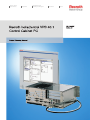
Rexroth IndraControl VPB 40.1 Control Cabinet PC
Rexroth IndraControl VPB 40.1
Control Cabinet PC
Type of Documentation
Document Typecode
Internal File Reference
Purpose of Documentation
Record of Revision
Copyright
Project Planning Manual
DOK-SUPPL*-VPB*40.1***-PR02-EN-P
RS-e5b02d3ca3a7f3010a6846a001c4f9bb-1-en-US-5
This documentation describes the control cabinet PC VPB 40.1
Edition
Release Date
Notes
120-2100-B384-01/EN
10.2005
First edition
120-2100-B384-02/EN
07.2010
Revised edition
© Bosch Rexroth AG, 2005
Copying this document, giving it to others and the use or communication of the
contents thereof without express authority, are forbidden. Offenders are liable
for the payment of damages. All rights are reserved in the event of the grant of
a patent or the registration of a utility model or design (DIN 34-1).
Validity
Published by
The specified data is for product description purposes only and may not be
deemed to be guaranteed unless expressly confirmed in the contract. All rights
are reserved with respect to the content of this documentation and the availa‐
bility of the product.
Bosch Rexroth AG
Bgm.-Dr.-Nebel-Str. 2 ■ 97816 Lohr am Main, Germany
Phone +49 (0)93 52/ 40-0 ■ Fax +49 (0)93 52/ 40-48 85
http://www.boschrexroth.com/
Development Control Platform HB (CS)
Note
This document has been printed on chlorine-free bleached paper.
DOK-SUPPL*-VPB*40.1***-PR02-EN-P
Rexroth IndraControl VPB 40.1 Control Cabinet PC
Bosch Rexroth AG
I/81
Table of Contents
Table of Contents
Page
1
1.1
1.2
1.2.1
1.3
1.4
2
2.1
2.1.1
2.1.2
2.2
3
3.1
3.2
3.2.1
3.2.2
3.2.3
3.3
3.3.1
3.3.2
3.3.3
3.3.4
3.3.5
3.3.6
3.3.7
3.3.8
3.4
4
4.1
4.2
4.3
4.4
4.5
4.6
4.6.1
4.6.2
4.7
4.8
4.9
System Presentation...................................................................................................... 5
Brief Description VPB 40.1..................................................................................................................... 5
Variants................................................................................................................................................... 5
Characteristic Features....................................................................................................................... 5
Operating System................................................................................................................................... 6
Commissioning....................................................................................................................................... 6
Important Instructions on Use ....................................................................................... 7
Appropriate Use ..................................................................................................................................... 7
Introduction.......................................................................................................................................... 7
Areas of Use and Application.............................................................................................................. 7
Inappropriate Use................................................................................................................................... 8
Safety Instructions for Electric Drives and Controls ...................................................... 9
Definitions of Terms................................................................................................................................ 9
General Information.............................................................................................................................. 10
Using the Safety Instructions and Passing Them on to Others......................................................... 10
Requirements for Safe Use............................................................................................................... 10
Hazards by Improper Use.................................................................................................................. 11
Instructions with Regard to Specific Dangers....................................................................................... 12
Protection Against Contact with Electrical Parts and Housings......................................................... 12
Protective Extra-Low Voltage as Protection Against Electric Shock ................................................ 13
Protection Against Dangerous Movements....................................................................................... 13
Protection Against Magnetic and Electromagnetic Fields During Operation and Mounting.............. 15
Protection Against Contact With Hot Parts........................................................................................ 15
Protection During Handling and Mounting......................................................................................... 15
Battery Safety.................................................................................................................................... 16
Protection Against Pressurized Systems........................................................................................... 16
Explanation of Signal Words and the Safety Alert Symbol................................................................... 17
Technical Data............................................................................................................. 19
PC Box.................................................................................................................................................. 19
Power Supply Unit 115 V / 230 V......................................................................................................... 19
24 V Voltage Supply............................................................................................................................. 20
Ambient Conditions............................................................................................................................... 21
Used Standards.................................................................................................................................... 21
CE Marking........................................................................................................................................... 22
Declaration of Conformity ................................................................................................................. 22
Note for the Machine Manufacturer................................................................................................... 22
UL/CSA Certified.................................................................................................................................. 23
Wear Parts............................................................................................................................................ 23
Compatibility Test................................................................................................................................. 24
II/81
Bosch Rexroth AG
DOK-SUPPL*-VPB*40.1***-PR02-EN-P
Rexroth IndraControl VPB 40.1 Control Cabinet PC
Table of Contents
Page
5
5.1
5.2
5.3
6
6.1
6.2
7
7.1
7.2
7.2.1
7.2.2
7.2.3
7.2.4
7.2.5
7.2.6
7.2.7
7.2.8
7.2.9
7.2.10
7.2.11
7.2.12
7.2.13
8
8.1
8.2
8.3
8.4
8.5
8.5.1
8.5.2
8.5.3
8.6
9
9.1
9.1.1
9.1.2
Dimensions, Installation............................................................................................... 25
General Information.............................................................................................................................. 25
Housing Dimensions............................................................................................................................. 25
Installation Notes.................................................................................................................................. 27
Display and Operating Components............................................................................ 29
Monitor and Keyboard.......................................................................................................................... 29
Operating and Error Display................................................................................................................. 29
Connections................................................................................................................. 31
View on the Connector Panel............................................................................................................... 31
Interfaces.............................................................................................................................................. 31
General Information........................................................................................................................... 31
Overview............................................................................................................................................ 31
Serial Interfaces XCOM1 to XCOM3 ................................................................................................ 32
Serial Interfaces, Settings.................................................................................................................. 33
Parallel Interface XLPT1.................................................................................................................... 34
USB Interfaces XUSB........................................................................................................................ 35
Ethernet Interface XEthernet............................................................................................................. 36
VGA Interface XVGA......................................................................................................................... 37
Combined Keyboard/Mouse Interface XKeyb................................................................................... 38
Mouse Interface XMouse................................................................................................................... 38
PC Voltage Supply X10, X20............................................................................................................. 40
Battery Connection X19..................................................................................................................... 44
Display Interfaces X71....................................................................................................................... 45
........................................................................................................................................................ 45
Maintenance and Installation....................................................................................... 47
General Information.............................................................................................................................. 47
Hard Disk.............................................................................................................................................. 47
CMOS Battery....................................................................................................................................... 49
Battery Pack......................................................................................................................................... 49
Extension Cards................................................................................................................................... 53
General Information........................................................................................................................... 53
Installing Extension Cards................................................................................................................. 53
BIOS Settings.................................................................................................................................... 56
Exchanging the Fuses.......................................................................................................................... 56
Software....................................................................................................................... 59
Application Software of the Monitoring Functions................................................................................. 59
Temperature Monitoring.................................................................................................................... 59
Uninterruptible Power Supply (UPS)................................................................................................. 59
General Information........................................................................................................................ 59
Operating Principle of the UPS....................................................................................................... 59
DOK-SUPPL*-VPB*40.1***-PR02-EN-P
Rexroth IndraControl VPB 40.1 Control Cabinet PC
Bosch Rexroth AG
III/81
Table of Contents
Page
9.2
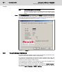
UPS NT Program ........................................................................................................................... 60
UPS NT - Operation and Configuration.......................................................................................... 61
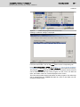
Touch Screen Software........................................................................................................................ 68
10
Environmental Protection and Disposal ...................................................................... 71
10.1
10.2
11
11.1
11.2
11.2.1
11.2.2
11.2.3
11.2.4
12
Environmental Protection...................................................................................................................... 71
Disposal................................................................................................................................................ 71
Ordering Information.................................................................................................... 73
Type Designation Code........................................................................................................................ 73
Accessories.......................................................................................................................................... 74
Network Connection.......................................................................................................................... 74
Battery Pack and cables.................................................................................................................... 74
Y-Repeater........................................................................................................................................ 74
Connecting Cable to VDP 16, VDP 40 and VDP 60 (G4 and G5 Display Interface)......................... 74
Service and Support.................................................................................................... 77
Index............................................................................................................................ 79
IV/81
Bosch Rexroth AG
DOK-SUPPL*-VPB*40.1***-PR02-EN-P
Rexroth IndraControl VPB 40.1 Control Cabinet PC
DOK-SUPPL*-VPB*40.1***-PR02-EN-P
Rexroth IndraControl VPB 40.1 Control Cabinet PC
Bosch Rexroth AG
5/81
System Presentation
1
System Presentation
1.1
Brief Description VPB 40.1
The VPB 40.1 is a control cabinet PC that forms a PC-based operator terminal
when combined with a VDP 16, VDP 40 or VDP 60 display. Depending on the
application or configuration, the operator terminal can also fulfill the control
functionalities.
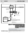
Fig.1-1:
VPB 40.1 with 3-slot box and connected display VDP (not included in
the scope of delivery)
The VPB 40.1 is connected to the G4 or G5 serial display interface of VDP 16,
VDP 40 or VDP 60 via a connecting cable with a length of up to 30 m. Thus,
the VPB 40.1 can be installed in the control cabinet and the display in its door
or at the machine.
The VPB 40.1 consists of two tightly connected parts:
●
The PC box contains the actual PC, including the hard disk and the power
supply unit with uninterruptible power supply (UPS). Depending on the
variant the PC box provides three or four slots. The standard interface and
some special interfaces are available on a plugboard.
●
The display interface and a RS422 interface (X39), which is to be used as
alternative for the 24 V interface XCOM1, are integrated in the second
housing part mounted on the PC box. Furthermore, five LEDs to display
device states and errors are arranged on this housing. Also, the optionally
available DVD ROM drive or the CD RW recorder system are mounted
here.
1.2
Variants
1.2.1
Characteristic Features
The VPB 40.1 is available in two different housing variants. The possible var‐
iants are described in the designation codes, see chapter 11.1 "Type Desig‐
nation Code" on page 73. Principally, they differ in the used PC box equipped
with 3 or 4 slots.
PC box
Type A
Type C
Free slots
3
4
Voltage supply
AC 85 V to AC 264 V
or DC 24 V
6/81
Bosch Rexroth AG
DOK-SUPPL*-VPB*40.1***-PR02-EN-P
Rexroth IndraControl VPB 40.1 Control Cabinet PC
System Presentation
PC box
Type A
Integrated UPS
Integrated UPS logic,
Type C
Battery packs to be connected externally
Optional drives
DVD-ROM,
DVD-ROM / CD-RW
Fig.1-2:
1.3
PC box, type A and type C
Operating System
For license reasons the VPB 40.1 is only delivered with already installed oper‐
ating system.
1.4
Commissioning
Mount the device properly, see also chapter 5 "Dimensions, Installation" on
page 25. Then connect the device to the power supply and, if required, to the
network.
DOK-SUPPL*-VPB*40.1***-PR02-EN-P
Rexroth IndraControl VPB 40.1 Control Cabinet PC
Bosch Rexroth AG
7/81
Important Instructions on Use
2
Important Instructions on Use
2.1
Appropriate Use
2.1.1
Introduction
Rexroth products represent state-of-the-art developments and manufacturing.
They are tested prior to delivery to ensure operational safety and reliability.
WARNING
Physical injury and material damage might re‐
sult from an inappropriate use of the products!
The products are designed for the use in an industrial environment and may
therefore only be used for the intended purpose. If they are not used as inten‐
ded, situations causing personal injury as well as material damage can occur.
Rexroth disclaims as manufacturer any warranty, liability or dam‐
ages occurring due to inappropriate use of the products. Further‐
more, Rexroth is not paying any compensation. The user is
responsible for any risks resulting from inappropriate use of the
products.
Before using Rexroth products, the following requirements must be met to en‐
sure appropriate use of the products:
2.1.2
●
Anyone handling one of the Rexroth products in any way has to read and
understand the respective safety-related guidelines as well as the instruc‐
tions on appropriate use.
●
Hardware products have to remain in their original state, in other words,
no modification regarding the design are allowed. Software products must
not be decompiled and their source codes must not be modified.
●
Damaged or faulty products must not be implemented or put into opera‐
tion.
●
It must be ensured that the products are installed as specified in the doc‐
umentation.
Areas of Use and Application
The VPB 40.1 by Rexroth is a control cabinet PC and becomes a PC-based
operator terminal when used with a VDP display. Depending on the application
and configuration, control functionality can also be carried out.
NOTICE
Danger of destruction of the device if not ex‐
pressly stated accessories, add-on compo‐
nents and other components, cables, conduits,
software and firmware is used.
The VPB 40.1 may only be used with the accessories and add-on components
specified in this documentation. Components not named expressly mentioned
must neither be mounted nor connected. The same applies to cables and con‐
duits.
The products may only be operated with the expressly stated configurations
and component combinations as well as with the software and firmware which
is given and specified in the respective functional description.
Typical areas of application of the VPB 40.1 are:
8/81
Bosch Rexroth AG
DOK-SUPPL*-VPB*40.1***-PR02-EN-P
Rexroth IndraControl VPB 40.1 Control Cabinet PC
Important Instructions on Use
●
Handling systems and assembly systems
●
Packaging and food processing machines
●
Printing machines and paper converting machines
●
Machine tools
●
Wood working machines
The VPB 40.1 may only be operated under the assembly conditions and in‐
stallation conditions, in the specified position of application and under the
specified ambient conditions (temperature, degree of protection, humidity, EMC
etc.) given in this documentation.
2.2
Inappropriate Use
The application of VPB 40.1 that are not whithin the specicified areas of appli‐
cation or under operating conditions deviating from the operating conditions
and technical data specified in the documentation are considered as "inappro‐
priate".
VPB 40.1 must not be used if ...
●
it is exposed to operating conditions that do not fulfill the ambient condi‐
tions specified. For instance, operation under water, in case of extreme
variations of temperature or in extreme maximum temperatures is not al‐
lowed.
●
the intended applications have not expressly been allowed by Rexroth.
Please note the general specifications in the general safety instructions!
DOK-SUPPL*-VPB*40.1***-PR02-EN-P
Rexroth IndraControl VPB 40.1 Control Cabinet PC
Bosch Rexroth AG
9/81
Safety Instructions for Electric Drives and Controls
3
Safety Instructions for Electric Drives and Controls
3.1
Definitions of Terms
Application Documentation
Application documentation comprises the entire documentation used to inform
the user of the product about the use and safety-relevant features for config‐
uring, integrating, installing, mounting, commissioning, operating, maintaining,
repairing and decommissioning the product. The following terms are also used
for this kind of documentation: User Guide, Operation Manual, Commissioning
Manual, Instruction Manual, Project Planning Manual, Application Manual, etc.
Component
A component is a combination of elements with a specified function, which are
part of a piece of equipment, device or system. Components of the electric drive
and control system are, for example, supply units, drive controllers, mains
choke, mains filter, motors, cables, etc.
Control System
A control system comprises several interconnected control components placed
on the market as a single functional unit.
Device
A device is a finished product with a defined function, intended for users and
placed on the market as an individual piece of merchandise.
Electrical Equipment
Electrical equipment encompasses all devices used to generate, convert, trans‐
mit, distribute or apply electrical energy, such as electric motors, transformers,
switching devices, cables, lines, power-consuming devices, circuit board as‐
semblies, plug-in units, control cabinets, etc.
Electric Drive System
An electric drive system comprises all components from mains supply to motor
shaft; this includes, for example, electric motor(s), motor encoder(s), supply
units and drive controllers, as well as auxiliary and additional components, such
as mains filter, mains choke and the corresponding lines and cables.
Installation
An installation consists of several devices or systems interconnected for a de‐
fined purpose and on a defined site which, however, are not intended to be
placed on the market as a single functional unit.
Machine
A machine is the entirety of interconnected parts or units at least one of which
is movable. Thus, a machine consists of the appropriate machine drive ele‐
ments, as well as control and power circuits, which have been assembled for
a specific application. A machine is, for example, intended for processing,
treatment, movement or packaging of a material. The term "machine" also cov‐
ers a combination of machines which are arranged and controlled in such a way
that they function as a unified whole.
Manufacturer
The manufacturer is an individual or legal entity bearing responsibility for the
design and manufacture of a product which is placed on the market in the in‐
dividual's or legal entity's name. The manufacturer can use finished products,
finished parts or finished elements, or contract out work to subcontractors.
However, the manufacturer must always have overall control and possess the
required authority to take responsibility for the product.
Product
Examples of a product: Device, component, part, system, software, firmware,
among other things.
Project Planning Manual
A project planning manual is part of the application documentation used to
support the sizing and planning of systems, machines or installations.
Qualified Persons
In terms of this application documentation, qualified persons are those persons
who are familiar with the installation, mounting, commissioning and operation
of the components of the electric drive and control system, as well as with the
hazards this implies, and who possess the qualifications their work requires. To
comply with these qualifications, it is necessary, among other things,
10/81
Bosch Rexroth AG
DOK-SUPPL*-VPB*40.1***-PR02-EN-P
Rexroth IndraControl VPB 40.1 Control Cabinet PC
Safety Instructions for Electric Drives and Controls
1) to be trained, instructed or authorized to switch electric circuits and devices
safely on and off, to ground them and to mark them
2) to be trained or instructed to maintain and use adequate safety equipment
3) to attend a course of instruction in first aid
User
A user is a person installing, commissioning or using a product which has been
placed on the market.
3.2
General Information
3.2.1
Using the Safety Instructions and Passing Them on to Others
Do not attempt to install and operate the components of the electric drive and
control system without first reading all documentation provided with the product.
Read and understand these safety instructions and all user documentation prior
to working with these components. If you do not have the user documentation
for the components, contact your responsible Bosch Rexroth sales partner. Ask
for these documents to be sent immediately to the person or persons respon‐
sible for the safe operation of the components.
If the component is resold, rented and/or passed on to others in any other form,
these safety instructions must be delivered with the component in the official
language of the user's country.
Improper use of these components, failure to follow the safety instructions in
this document or tampering with the product, including disabling of safety de‐
vices, could result in property damage, injury, electric shock or even death.
3.2.2
Requirements for Safe Use
Read the following instructions before initial commissioning of the components
of the electric drive and control system in order to eliminate the risk of injury
and/or property damage. You must follow these safety instructions.
●
Bosch Rexroth is not liable for damages resulting from failure to observe
the safety instructions.
●
Read the operating, maintenance and safety instructions in your language
before commissioning. If you find that you cannot completely understand
the application documentation in the available language, please ask your
supplier to clarify.
●
Proper and correct transport, storage, mounting and installation, as well
as care in operation and maintenance, are prerequisites for optimal and
safe operation of the component.
●
Only qualified persons may work with components of the electric drive and
control system or within its proximity.
●
Only use accessories and spare parts approved by Bosch Rexroth.
●
Follow the safety regulations and requirements of the country in which the
components of the electric drive and control system are operated.
●
Only use the components of the electric drive and control system in the
manner that is defined as appropriate. See chapter "Appropriate Use".
●
The ambient and operating conditions given in the available application
documentation must be observed.
●
Applications for functional safety are only allowed if clearly and explicitly
specified in the application documentation "Integrated Safety Technolo‐
gy". If this is not the case, they are excluded. Functional safety is a safety
DOK-SUPPL*-VPB*40.1***-PR02-EN-P
Rexroth IndraControl VPB 40.1 Control Cabinet PC
Bosch Rexroth AG
11/81
Safety Instructions for Electric Drives and Controls
concept in which measures of risk reduction for personal safety depend
on electrical, electronic or programmable control systems.
●
The information given in the application documentation with regard to the
use of the delivered components contains only examples of applications
and suggestions.
The machine and installation manufacturers must
–
make sure that the delivered components are suited for their individ‐
ual application and check the information given in this application
documentation with regard to the use of the components,
–
make sure that their individual application complies with the appli‐
cable safety regulations and standards and carry out the required
measures, modifications and complements.
●
Commissioning of the delivered components is only allowed once it is sure
that the machine or installation in which the components are installed
complies with the national regulations, safety specifications and standards
of the application.
●
Operation is only allowed if the national EMC regulations for the applica‐
tion are met.
●
The instructions for installation in accordance with EMC requirements can
be found in the section on EMC in the respective application documenta‐
tion.
The machine or installation manufacturer is responsible for compliance
with the limit values as prescribed in the national regulations.
●
The technical data, connection and installation conditions of the compo‐
nents are specified in the respective application documentations and must
be followed at all times.
National regulations which the user must take into account
●
European countries: In accordance with European EN standards
●
United States of America (USA):
–
National Electrical Code (NEC)
–
National Electrical Manufacturers Association (NEMA), as well as
local engineering regulations
–
Regulations of the National Fire Protection Association (NFPA)
●
Canada: Canadian Standards Association (CSA)
●
Other countries:
–
International Organization for Standardization (ISO)
–
International Electrotechnical Commission (IEC)
3.2.3
Hazards by Improper Use
●
High electrical voltage and high working current! Danger to life or serious
injury by electric shock!
●
High electrical voltage by incorrect connection! Danger to life or injury by
electric shock!
●
Dangerous movements! Danger to life, serious injury or property damage
by unintended motor movements!
●
Health hazard for persons with heart pacemakers, metal implants and
hearing aids in proximity to electric drive systems!
●
Risk of burns by hot housing surfaces!
12/81
Bosch Rexroth AG
DOK-SUPPL*-VPB*40.1***-PR02-EN-P
Rexroth IndraControl VPB 40.1 Control Cabinet PC
Safety Instructions for Electric Drives and Controls
●
Risk of injury by improper handling! Injury by crushing, shearing, cutting,
hitting!
●
Risk of injury by improper handling of batteries!
●
Risk of injury by improper handling of pressurized lines!
3.3
Instructions with Regard to Specific Dangers
3.3.1
Protection Against Contact with Electrical Parts and Housings
This section concerns components of the electric drive and control
system with voltages of more than 50 volts.
Contact with parts conducting voltages above 50 volts can cause personal
danger and electric shock. When operating components of the electric drive
and control system, it is unavoidable that some parts of these components
conduct dangerous voltage.
High electrical voltage! Danger to life, risk of injury by electric shock or serious
injury!
●
Only qualified persons are allowed to operate, maintain and/or repair the
components of the electric drive and control system.
●
Follow the general installation and safety regulations when working on
power installations.
●
Before switching on, the equipment grounding conductor must have been
permanently connected to all electric components in accordance with the
connection diagram.
●
Even for brief measurements or tests, operation is only allowed if the
equipment grounding conductor has been permanently connected to the
points of the components provided for this purpose.
●
Before accessing electrical parts with voltage potentials higher than 50 V,
you must disconnect electric components from the mains or from the pow‐
er supply unit. Secure the electric component from reconnection.
●
With electric components, observe the following aspects:
Always wait 30 minutes after switching off power to allow live capacitors
to discharge before accessing an electric component. Measure the elec‐
trical voltage of live parts before beginning to work to make sure that the
equipment is safe to touch.
●
Install the covers and guards provided for this purpose before switching
on.
●
Never touch electrical connection points of the components while power
is turned on.
●
Do not remove or plug in connectors when the component has been pow‐
ered.
●
Under specific conditions, electric drive systems can be operated at mains
protected by residual-current-operated circuit-breakers sensitive to uni‐
versal current (RCDs/RCMs).
●
Secure built-in devices from penetrating foreign objects and water, as well
as from direct contact, by providing an external housing, for example a
control cabinet.
DOK-SUPPL*-VPB*40.1***-PR02-EN-P
Rexroth IndraControl VPB 40.1 Control Cabinet PC
Bosch Rexroth AG
13/81
Safety Instructions for Electric Drives and Controls
High housing voltage and high leakage current! Danger to life, risk of injury by
electric shock!
3.3.2
●
Before switching on and before commissioning, ground or connect the
components of the electric drive and control system to the equipment
grounding conductor at the grounding points.
●
Connect the equipment grounding conductor of the components of the
electric drive and control system permanently to the main power supply at
all times. The leakage current is greater than 3.5 mA.
●
Establish an equipment grounding connection with a copper wire of a
cross section of at least 10 mm2 (8 AWG) or additionally run a second
equipment grounding conductor of the same cross section as the original
equipment grounding conductor.
Protective Extra-Low Voltage as Protection Against Electric Shock
Protective extra-low voltage is used to allow connecting devices with basic in‐
sulation to extra-low voltage circuits.
On components of an electric drive and control system provided by Bosch
Rexroth, all connections and terminals with voltages between 5 and 50 volts
are PELV ("Protective Extra-Low Voltage") systems. It is allowed to connect
devices equipped with basic insulation (such as programming devices, PCs,
notebooks, display units) to these connections.
Danger to life, risk of injury by electric shock! High electrical voltage by incorrect
connection!
If extra-low voltage circuits of devices containing voltages and circuits of more
than 50 volts (e.g., the mains connection) are connected to Bosch Rexroth
products, the connected extra-low voltage circuits must comply with the re‐
quirements for PELV ("Protective Extra-Low Voltage").
3.3.3
Protection Against Dangerous Movements
Dangerous movements can be caused by faulty control of connected motors.
Some common examples are:
●
Improper or wrong wiring or cable connection
●
Operator errors
●
Wrong input of parameters before commissioning
●
Malfunction of sensors and encoders
●
Defective components
●
Software or firmware errors
These errors can occur immediately after equipment is switched on or even
after an unspecified time of trouble-free operation.
The monitoring functions in the components of the electric drive and control
system will normally be sufficient to avoid malfunction in the connected drives.
Regarding personal safety, especially the danger of injury and/or property dam‐
age, this alone cannot be relied upon to ensure complete safety. Until the
integrated monitoring functions become effective, it must be assumed in any
case that faulty drive movements will occur. The extent of faulty drive move‐
ments depends upon the type of control and the state of operation.
14/81
Bosch Rexroth AG
DOK-SUPPL*-VPB*40.1***-PR02-EN-P
Rexroth IndraControl VPB 40.1 Control Cabinet PC
Safety Instructions for Electric Drives and Controls
Dangerous movements! Danger to life, risk of injury, serious injury or property
damage!
A risk assessment must be prepared for the installation or machine, with its
specific conditions, in which the components of the electric drive and control
system are installed.
As a result of the risk assessment, the user must provide for monitoring func‐
tions and higher-level measures on the installation side for personal safety. The
safety regulations applicable to the installation or machine must be taken into
consideration. Unintended machine movements or other malfunctions are pos‐
sible if safety devices are disabled, bypassed or not activated.
To avoid accidents, injury and/or property damage:
●
Keep free and clear of the machine’s range of motion and moving machine
parts. Prevent personnel from accidentally entering the machine’s range
of motion by using, for example:
–
Safety fences
–
Safety guards
–
Protective coverings
–
Light barriers
●
Make sure the safety fences and protective coverings are strong enough
to resist maximum possible kinetic energy.
●
Mount emergency stopping switches in the immediate reach of the oper‐
ator. Before commissioning, verify that the emergency stopping equip‐
ment works. Do not operate the machine if the emergency stopping switch
is not working.
●
Prevent unintended start-up. Isolate the drive power connection by means
of OFF switches/OFF buttons or use a safe starting lockout.
●
Make sure that the drives are brought to safe standstill before accessing
or entering the danger zone.
●
Additionally secure vertical axes against falling or dropping after switching
off the motor power by, for example,
–
mechanically securing the vertical axes,
–
adding an external braking/arrester/clamping mechanism or
–
ensuring sufficient counterbalancing of the vertical axes.
●
The standard equipment motor holding brake or an external holding brake
controlled by the drive controller is not sufficient to guarantee personal
safety!
●
Disconnect electrical power to the components of the electric drive and
control system using the master switch and secure them from reconnec‐
tion ("lock out") for:
●
–
Maintenance and repair work
–
Cleaning of equipment
–
Long periods of discontinued equipment use
Prevent the operation of high-frequency, remote control and radio equip‐
ment near components of the electric drive and control system and their
supply leads. If the use of these devices cannot be avoided, check the
machine or installation, at initial commissioning of the electric drive and
control system, for possible malfunctions when operating such high-fre‐
quency, remote control and radio equipment in its possible positions of
normal use. It might possibly be necessary to perform a special electro‐
magnetic compatibility (EMC) test.
DOK-SUPPL*-VPB*40.1***-PR02-EN-P
Rexroth IndraControl VPB 40.1 Control Cabinet PC
Bosch Rexroth AG
15/81
Safety Instructions for Electric Drives and Controls
3.3.4
Protection Against Magnetic and Electromagnetic Fields During Oper‐
ation and Mounting
Magnetic and electromagnetic fields generated by current-carrying conductors
or permanent magnets of electric motors represent a serious danger to persons
with heart pacemakers, metal implants and hearing aids.
Health hazard for persons with heart pacemakers, metal implants and hearing
aids in proximity to electric components!
●
3.3.5
Persons with heart pacemakers and metal implants are not allowed to
enter the following areas:
–
Areas in which components of the electric drive and control systems
are mounted, commissioned and operated.
–
Areas in which parts of motors with permanent magnets are stored,
repaired or mounted.
●
If it is necessary for somebody with a heart pacemaker to enter such an
area, a doctor must be consulted prior to doing so. The noise immunity of
implanted heart pacemakers differs so greatly that no general rules can
be given.
●
Those with metal implants or metal pieces, as well as with hearing aids,
must consult a doctor before they enter the areas described above.
Protection Against Contact With Hot Parts
Hot surfaces of components of the electric drive and control system. Risk of
burns!
3.3.6
●
Do not touch hot surfaces of, for example, braking resistors, heat sinks,
supply units and drive controllers, motors, windings and laminated cores!
●
According to the operating conditions, temperatures of the surfaces can
be higher than 60 °C (140 °F) during or after operation.
●
Before touching motors after having switched them off, let them cool down
for a sufficient period of time. Cooling down can require up to 140 mi‐
nutes! The time required for cooling down is approximately five times the
thermal time constant specified in the technical data.
●
After switching chokes, supply units and drive controllers off, wait 15 mi‐
nutes to allow them to cool down before touching them.
●
Wear safety gloves or do not work at hot surfaces.
●
For certain applications, and in accordance with the respective safety reg‐
ulations, the manufacturer of the machine or installation must take meas‐
ures to avoid injuries caused by burns in the final application. These
measures can be, for example: Warnings at the machine or installation,
guards (shieldings or barriers) or safety instructions in the application
documentation.
Protection During Handling and Mounting
Risk of injury by improper handling! Injury by crushing, shearing, cutting, hitting!
●
Observe the relevant statutory regulations of accident prevention.
●
Use suitable equipment for mounting and transport.
●
Avoid jamming and crushing by appropriate measures.
16/81
Bosch Rexroth AG
DOK-SUPPL*-VPB*40.1***-PR02-EN-P
Rexroth IndraControl VPB 40.1 Control Cabinet PC
Safety Instructions for Electric Drives and Controls
3.3.7
●
Always use suitable tools. Use special tools if specified.
●
Use lifting equipment and tools in the correct manner.
●
Use suitable protective equipment (hard hat, safety goggles, safety shoes,
safety gloves, for example).
●
Do not stand under hanging loads.
●
Immediately clean up any spilled liquids from the floor due to the risk of
slipping.
Battery Safety
Batteries consist of active chemicals in a solid housing. Therefore, improper
handling can cause injury or property damage.
Risk of injury by improper handling!
●
Do not attempt to reactivate low batteries by heating or other methods (risk
of explosion and cauterization).
●
Do not attempt to recharge the batteries as this may cause leakage or
explosion.
●
Do not throw batteries into open flames.
●
Do not dismantle batteries.
●
When replacing the battery/batteries, do not damage the electrical parts
installed in the devices.
●
Only use the battery types specified for the product.
Environmental protection and disposal! The batteries contained in
the product are considered dangerous goods during land, air, and
sea transport (risk of explosion) in the sense of the legal regulations.
Dispose of used batteries separately from other waste. Observe the
national regulations of your country.
3.3.8
Protection Against Pressurized Systems
According to the information given in the Project Planning Manuals, motors and
components cooled with liquids and compressed air can be partially supplied
with externally fed, pressurized media, such as compressed air, hydraulics oil,
cooling liquids and cooling lubricants. Improper handling of the connected sup‐
ply systems, supply lines or connections can cause injuries or property damage.
Risk of injury by improper handling of pressurized lines!
●
Do not attempt to disconnect, open or cut pressurized lines (risk of explo‐
sion).
●
Observe the respective manufacturer's operating instructions.
●
Before dismounting lines, relieve pressure and empty medium.
●
Use suitable protective equipment (safety goggles, safety shoes, safety
gloves, for example).
●
Immediately clean up any spilled liquids from the floor due to the risk of
slipping.
DOK-SUPPL*-VPB*40.1***-PR02-EN-P
Rexroth IndraControl VPB 40.1 Control Cabinet PC
Bosch Rexroth AG
17/81
Safety Instructions for Electric Drives and Controls
Environmental protection and disposal! The agents (e.g., fluids)
used to operate the product might not be environmentally friendly.
Dispose of agents harmful to the environment separately from other
waste. Observe the national regulations of your country.
3.4
Explanation of Signal Words and the Safety Alert Symbol
The Safety Instructions in the available application documentation contain spe‐
cific signal words (DANGER, WARNING, CAUTION or NOTICE) and, where
required, a safety alert symbol (in accordance with ANSI Z535.6-2006).
The signal word is meant to draw the reader's attention to the safety instruction
and identifies the hazard severity.
The safety alert symbol (a triangle with an exclamation point), which precedes
the signal words DANGER, WARNING and CAUTION, is used to alert the
reader to personal injury hazards.
DANGER
In case of non-compliance with this safety instruction, death or serious injury
will occur.
WARNING
In case of non-compliance with this safety instruction, death or serious injury
could occur.
CAUTION
In case of non-compliance with this safety instruction, minor or moderate injury
could occur.
NOTICE
In case of non-compliance with this safety instruction, property damage could
occur.
18/81
Bosch Rexroth AG
DOK-SUPPL*-VPB*40.1***-PR02-EN-P
Rexroth IndraControl VPB 40.1 Control Cabinet PC
DOK-SUPPL*-VPB*40.1***-PR02-EN-P
Rexroth IndraControl VPB 40.1 Control Cabinet PC
Bosch Rexroth AG
19/81
Technical Data
4
Technical Data
4.1
PC Box
PC box
Type C
Type A
Celeron-M, 1.3 GHz
Processor
RAM
Hard disk
Pentium-M 1.8 GHz
and integrated graphics controller
with a maximum of 8 MB video memory
512 MB
1 GB
Min. 30 GB, mounted within a vibration-resistant suspension
Optional drives DVD ROM or DVD ROM / CD RW
Interfaces
Slots
●
1 × display interface (25-pin, D-Sub)
●
1 × parallel interface (25-pin, D-Sub)
●
1 x external VGA connection (15-pin, HD-Sub)
●
2 × USB connection (type A)
●
1 × Ethernet connection (RJ 45, 10/100 base-T)
●
1 × keyboard connection (PS/2)
●
1 × mouse connection (PS/2)
●
1 x external battery connection
●
3 x serial standard interfaces RS232 (9-pin, D-Sub)1)
●
1 × RS422 interface (9-pin, D-Sub)
3 × PCI, 1 × PCI / ISA
2 × PCI, 1 × PCI / ISA
Degree of pro‐
PC box: IP 20
tection
Voltage supply
AC 85 V to AC 264 V or DC 24 V
Max.
power
200 W
consumption
without CD-ROM 6.1 kg
Weight
with CD-ROM + 0.2 kg additionally
for 4th slot + 0.1 kg additionally
Fig.4-1:
4.2
Technical data of the PC box
Power Supply Unit 115 V / 230 V
Nominal input voltage
AC 115 V or AC 230 V
Input voltage range
AC 85 V... AC 264 V
Input current
1.0 A for nominal voltage AC 230 V
2.0 A for nominal voltage AC 115 V
1)
For connected display: two serial interfaces
20/81
Bosch Rexroth AG
DOK-SUPPL*-VPB*40.1***-PR02-EN-P
Rexroth IndraControl VPB 40.1 Control Cabinet PC
Technical Data
Max. inrush current
40 A for nominal voltage AC 230 V
(cold start 25 °C)
20 A for nominal voltage AC 115 V
Output voltages
Current (max.)
Tolerance (incl. residual ripple)
+5 V
20 A
±5 %
+12 V
3A
±5 %
-12 V
500 mA
±5 %
+20 V
2A
±5 %
ISO 6 V
200 mA
±5 %
Maximum output power
160 W
Efficiency
0.8
Fig.4-2:
Technical data of the power supply unit 115 V / 230 V
NOTICE
The control cabinet PC VPB 40.1 can be dam‐
aged if the power supply unit is switched off if
the total output power exceeds 160 W.
When maximum output currents are specified, please observe that the currents
are the maximum possible currents for the respective output voltage. However,
it is not possible to produce the maximum current from all output voltages, as
the maximum total output power of 160 W must not be exceeded.
4.3
24 V Voltage Supply
Nominal input voltage
DC 24 V
Input voltage range
DC 24 V +20 %, -15 %
Emitted interference and surge Umax = 35 V (for t < 100 ms)
immunity
Max. input current
6 A for nominal voltage 24 V
Max. inrush current
25 A for nominal voltage 24 V
Output voltages
Current (max.)
Tolerance (incl. residual ripple)
+5 V
13 A
±5 %
+12 V
3A
±5 %
+24 V
2A
±5 %
-12 V
500 mA
±5 %
ISO 6 V
200 mA
±5 %
Max. output power
110 W
Efficiency
0.8
Fig.4-3:
Technical data of the 24 V power supply unit
DOK-SUPPL*-VPB*40.1***-PR02-EN-P
Rexroth IndraControl VPB 40.1 Control Cabinet PC
Bosch Rexroth AG
21/81
Technical Data
NOTICE
The control cabinet PC VPB 40.1 can be dam‐
aged if the power supply unit is switched off if
the total output power exceeds 110 W.
When maximum output currents are specified, please observe that the currents
are the maximum possible currents for the respective output voltage. However,
it is not possible to produce the maximum current from all output voltages at
the same time, as the maximum total output power (= max. 110 W) must not
be exceeded.
4.4
Ambient Conditions
In operation
Storage / Transport
Max. surrounding air temperature
+5 ℃ ... +45 °C
-20 ℃ to +60 ℃
Max. temperature gradient
Temporal temperature changes up to 3 ℃ Not defined
per minute
Relative humidity
Climatic class 3K3 according to EN Climatic class 3K3 according to EN
60721,
60721,
non-condensing.
non-condensing.
Air pressure
Up to 2000 m above MSL according to
DIN 60204
Mechanical strength
Max. vibration:
Max. shock:
Frequency range:
15 g acc. to DIN IEC 68-2-27,
10 to 150 Hz
No breakdown of the function
Excursion: 0.075 mm for 10 ... 57 Hz
Acceleration: 1 g for 57 to 150 Hz
acc. to EN 60068-2-6
Degree of pollution
2
Fig.4-4:
4.5
2
Ambient conditions
Used Standards
The system components of the VPB 40.1 correspond to the following standards:
Standard
Meaning
EN 60 204-1
Electrical equipment of machines
EN 50 081-2
Generic standards - emission standard (industrial envi‐
ronments)
EN 50 082-2
Generic standards - noise immunity (industrial environ‐
ments)
EN 60 742
Transformer for 24 V power supply unit, protective sepa‐
ration
EN 60 950
Overvoltage category II
EN 61 131
24 V outputs requirements
EN 61 131-2
24 V current supply requirements
EN 418
Safety of machinery, emergency stop devices
22/81
Bosch Rexroth AG
DOK-SUPPL*-VPB*40.1***-PR02-EN-P
Rexroth IndraControl VPB 40.1 Control Cabinet PC
Technical Data
Standard
Meaning
EN 60 529
Degrees of protection (including housings and installation
compartments)
EN 60 068-2-6
Vibration test
EN 60 068-2-27
Shock test
Fig.4-5:
Used standards
4.6
CE Marking
4.6.1
Declaration of Conformity
The electronic products described in the project planning manual comply with
the requirements and goals of the following EC guideline and with the agreed
European standards:
EMC guideline 2004/108/EC
The electronic products described in the project planning manual comply with
the requirements on the operation within the industrial environment:
Standard
Title
Edition
DIN EN
61000-6-4
Electromagnetic compatibility (EMC)
DIN EN
61000-6-2
Electromagnetic compatibility (EMC)
September
Volume: 6-4: Generic standards - emitted interfer‐ 2007
(VDE 0839-6-4) ence for industrial environments (IEC
61000-6-4:2006)
March 2006
Volume: 6-2: Generic standards – noise immunity
(VDE 0839-6-2) for industrial environments (IEC 61000-6-2:2005)
Fig.4-6:
4.6.2
Electromagnetic compatibility (EMC) standards
Note for the Machine Manufacturer
The electronic products described in this project planning manual do not fall
under the machines listed in the EC guidelines. Therefore, explanations are not
required for the 89/392/EMC guideline and do not exist.
89/392/EMC, the EC guideline for machines, specifies the requirements on a
machine. In this guideline, a machine is defined as a combination of the com‐
ponents or mechanisms combined with each other. The described products
belong to the electrical equipment of a machine. Therefore, they are to be in‐
cluded in the declaration of conformity of the machine manufacturer.
The standard EN 60204-1 (safety of machinery, general requirements on the
electrical equipment of the machines) can be used for the electrical equipment
of the machines.
NOTICE
Loss of CE conformity due to modifications of
the device.
The CE marking is only valid for the device in its delivery status. After modifying
the device, the CE conformity is to be verified.
DOK-SUPPL*-VPB*40.1***-PR02-EN-P
Rexroth IndraControl VPB 40.1 Control Cabinet PC
Bosch Rexroth AG
23/81
Technical Data
4.7
UL/CSA Certified
The devices of the IndraControl VPB 40.1 family are certificated according to
●
UL508 (Industrial Control Equipment) and
●
C22.2 no. 142-M1987 (CSA)
UL file no. E210730
However, there can be combinations or extension stages with limited or missing
certification. Thus, verify the certification by using the UL marking on the device.
To guarantee an UL/CSA-compliant operation, the following condi‐
tions have to be fulfilled:
●
Use only insulated copper wire suitable for at least 60/75 °C.
NOTICE
Loss of UL/CSA compliance due to changes on
the device.
The UL/CSA marking is only valid for the device in its delivery status (ex works).
After having modified the device the UL/CSA compliance must be verified.
4.8
Wear Parts
Wear parts without warranty:
CMOS battery
The service life of a CMOS battery is at least five years. To exchange this bat‐
tery, please contact the Bosch Rexroth Service.
Battery
The number of charging cycles of the battery pack and thus, its service life is
dependent on the surrounding air temperature, in which the battery pack is
used. Surrounding air temperature is defined as the temperature, in which the
control cabinet PC or the battery pack is situated, e.g. the internal temperature
of the control cabinet or in a operator panel housing.
Surrounding air temperature
Maintenance interval
25 °C
10 years
35 °C
5 years
45 ℃
2.5 years
Fig.4-7:
Battery pack: Maintenance interval: external battery pack for top-hat rail
mounting and for screw mounting
If you do not know exactly the conditions, Bosch Rexroth recommends you to
exchange the battery pack every 1.5 years.
Hard disk
The hard disk is an electromechanical component that is subject to wear during
the operating time. According to the manufacturer's data the hard disk has been
developed for a service life of 60 months in consideration of the following con‐
ditions:
Operating hours / month
Max. 333
Input/output cycles / month
Min. 10 and max. 150
24/81
Bosch Rexroth AG
DOK-SUPPL*-VPB*40.1***-PR02-EN-P
Rexroth IndraControl VPB 40.1 Control Cabinet PC
Technical Data
Operating conditions
Storage conditions
Fig.4-8:
Temperature
40 ℃
Relative humidity
30 %
Height
< 500 m
Accesses
30 % of the operating hours
Temperature
< 30 °C
Relative humidity
< 70 %
Duration
< 3 months
Typical operating and storage conditions of the hard disk
The operation out of this typical conditions is permissible, whereby, however,
the service life of the hard disk may reduce. The ambient conditions specified
for the overall device (see fig. 4-4 "Ambient conditions" on page 21) must be
observed.
Fan
Fans are mechanic wear components, whose service life is extremely temper‐
ature-dependent. For the fan integrated in the housing, the following service
life is specified by the manufacturer:
Surrounding air temperature
Service life
40 ℃
70 000 hours
70 ℃
35 000 Stunden
Fig.4-9:
4.9
Service life of the fan
Compatibility Test
All Rexroth controls and drives are developed and tested according to the latest
state-of-the-art of technology.
As it is impossible to follow the continuing development of all materials (e. g.
lubricants in machine tools) which may interact with our controls and drives, it
cannot be completely ruled out that any reactions with the materials used by
Bosch Rexroth might occur.
For this reason, before using the respective material a compatibility test has to
be carried out for new lubricants, cleaning agents etc. and our housings / our
housing materials.
DOK-SUPPL*-VPB*40.1***-PR02-EN-P
Rexroth IndraControl VPB 40.1 Control Cabinet PC
Bosch Rexroth AG
25/81
Dimensions, Installation
5
Dimensions, Installation
5.1
General Information
All values are given in mm.
5.2
Housing Dimensions
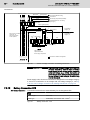
The VPB 40.1 can be mounted, e. g. in the control cabinet with the help of four
fastening holes. For the corresponding dimensions, please refer to figures fig.
5-1 "Horizontal mounting of the VPB 40.1 (device with 3-slot box)" on page
25 and fig. 5-5 "VPB 40.1 dimensions (top view)" on page 27.
The VPB 40.1 can be mounted horizontally (net connection on the left side) as
well as vertically (net connection on the top).
364
350
X20
7
A3
30
A2
A1
XDP
XCOM3
130,2
X19
XMouse
1
XUSB1
85
1
F1
XCOM1
X10
S1
XCOM2
XVGA
1
XEthernet XKeyb. XUSB2
1
X39
Fig.5-1:
X71
XLPT1
VI Vo T UPS HD
Horizontal mounting of the VPB 40.1 (device with 3-slot box)
The height of the VPB 40.1 depends on the number of slots of the used PC box:
PC box
Number of slots
VPB 40.1 height
Type A
3
130.2 mm (plus 10 mm for the screw of the hard
disk cover)
Type C
4
150.5 mm (plus 10 mm for the screw of the hard
disk cover)
Fig.5-2:
VPB 40.1 height
26/81
Bosch Rexroth AG
DOK-SUPPL*-VPB*40.1***-PR02-EN-P
Rexroth IndraControl VPB 40.1 Control Cabinet PC
Dimensions, Installation
X20
F1
X19
X10
1
XCOM3
XCOM1
1
S1
XDP
XCOM2
364
350
A3
A2
A1
X39
XVGA
1
XMouse
XUSB1
X71
XEthernet XKeyb. XUSB2
1
XLPT1
VI Vo T UPS HD
7
30
85
130,2
Fig.5-3:
Vertical mounting of the VPB 40.1 (device with 3-slot box)
The width of the VPB 40.1 depends on the number of slots of the used PC box:
PC box
Number of slots
VPB 40.1 width
Type A
3
130.2 mm (plus 10 mm for the screw of the hard
disk cover)
Type C
4
150.5 mm (plus 10 mm for the screw of the hard
disk cover)
Fig.5-4:
VPB 40.1 width
DOK-SUPPL*-VPB*40.1***-PR02-EN-P
Rexroth IndraControl VPB 40.1 Control Cabinet PC
Bosch Rexroth AG
27/81
214
262,5
Dimensions, Installation
Fig.5-5:
5.3
VPB 40.1 dimensions (top view)
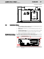
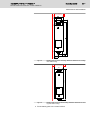
Installation Notes
Minimum distances for cooling, ca‐
bles, DVD drive and maintenance
●
Avoid installation locations exposed to direct sunlight/UV-light because
this causes additional heat development.
●
Install the control cabinet PC in a way ensuring easy access to the con‐
nector panel.
●
Provide a sufficient space of 50 mm (on all sides of the device) for sufficient
cooling and cable routing.
●
Lay all connecting cables in loops and use strain reliefs for all cables.
●
Keep as much distance as possible to noise sources.
For cooling, cables, maintenance and the DVD drive the following minimum
distances must be observed as shown in the following figures:
Provide sufficient distance for
hard disk replacement, if necessary
25
10
X20
A3
A2
A1
X19
XDP
XCOM3
XMouse
1
XUSB1
1
min. 50
F1
X10
XCOM1
1
S1
XCOM2
XEthernet
XVGA
1
X39
Fig.5-6:
XKeyb.
XUSB2
1
X71
XLPT1
VI Vo T UPS HD
Minimum distances for cooling, cables, DVD drive and maintenance:
Front View
28/81
Bosch Rexroth AG
DOK-SUPPL*-VPB*40.1***-PR02-EN-P
Rexroth IndraControl VPB 40.1 Control Cabinet PC
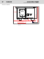
min. 50
214
50
Provide sufficient distance to open
the DVD drive, if necessary
(DVD tray opens 130 mm).
Fig.5-7:
300 (depends on the connector and bending radius of the cable)
Dimensions, Installation
VDP connecting cable
Minimum distances for cooling, cables, DVD drive and maintenance:
Top view
DOK-SUPPL*-VPB*40.1***-PR02-EN-P
Rexroth IndraControl VPB 40.1 Control Cabinet PC
Bosch Rexroth AG
29/81
Display and Operating Components
6
Display and Operating Components
6.1
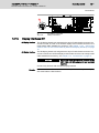
Monitor and Keyboard
Displays with foil keyboard and
touch screen
To display and operate the VPB 40.1 we recommend the displays VDP 16,
VDP 40 and VDP 60 especially designed by Bosch Rexroth for industrial ap‐
plications. The displays are connected with the VPB 40.1 via the G5 display
interface. These displays are equipped either with a keypad or with a touch
screen with varying display size.
For detailed information, please refer to the relevant documenta‐
tion.
Connection monitor
A standard monitor (female connector XVGA), a PS2 keyboard (female con‐
nector XKeyb.) and a PS2 mouse (female connector XMouse) can be also
connected with the VPB 40.1. Please observe that most of the standard mice
and keyboards are not suitable for the industrial environment and are very sus‐
ceptible to electromagnetic disturbances.
NOTICE
The VPB 40.1 control cabinet PC cannot be
operated if keyboard and mouse are connec‐
ted to the VPB 40.1 if a VDP display is used.
If a VDP is used, keyboard and mouse may only be connected to this display.
Don't use the keyboard and mouse interfaces at the VPB 40.1.
6.2
Operating and Error Display
In the lower right part of the connector panel there are five LEDs to display the
device states and errors. Apply the specified measure if one of the following
LEDs display either an error or a note.
LEDs for operating and error dis‐
play
LED
Display
Vi
LED green Normal mode
LED off
Vo
T
Meaning
Measure
-
No supply voltage AC 230 V/115 V Check the supply voltage
or DC 24 V
at the power supply unit!
LED green Normal mode
-
LED off
Internal 5 V supply faulty!
-
LED off
Normal mode
LED flash‐ Overtemperature
es yellow
Reduce surrounding air
temperature!
Check fan on the control
cabinet PC!
30/81
Bosch Rexroth AG
DOK-SUPPL*-VPB*40.1***-PR02-EN-P
Rexroth IndraControl VPB 40.1 Control Cabinet PC
Display and Operating Components
LED
Display
Meaning
Measure
UPS
LED off
Normal mode
-
LED red
VPB 40.1 is currently operating in Restore power supply and
battery mode, i. e. no voltage sup‐ initiate controlled restart!
ply is available!
LED flash‐ Battery pack discharged, defective Check battery!
es red
or not connected
Maintain the charging time
of 5 hours!
HDD
Fig.6-1:
LED yellow Hard disk access
-
LEDs to operating and error display on the connector panel
DOK-SUPPL*-VPB*40.1***-PR02-EN-P
Rexroth IndraControl VPB 40.1 Control Cabinet PC
Bosch Rexroth AG
31/81
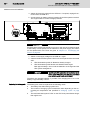
Connections
7
Connections
7.1
View on the Connector Panel
X20
A3
A2
A1
X19
XDP
XCOM3
XMouse
1
XUSB1
1
F1
X10
1
XCOM1
S1
XCOM2
XEthernet
XVGA
1
XKeyb.
XUSB2
1
X71
X39
Fig.7-1:
7.2
Interfaces
7.2.1
General Information
XLPT1
VI Vo T UPS HD
Position of the connections
Not each variant provides all the described interfaces. Which inter‐
faces are integrated in the respective device depends on the device
configuration.
NOTICE
Malfunctions due to insufficient shielding!
Use only shielded cables and metallic, conductive connectors or coupling hous‐
ings with large-area shield support.
7.2.2
Overview
Interfaces - Overview
Designa‐
Connection type
tion at the
housing
Connector type (in‐ Mating connector or
tegrated)
cable (from outside)
XCOM1,
XCOM2,
XCOM3
Serial interfaces:
D-Sub male con‐ D-Sub female con‐
nector, 9-pin
nector, 9-pin
XLPT1
Parallel interface: supports D-Sub female con‐ D-Sub male con‐
standard SPP-, EPP-, ECP- nector, 25-pin
nector, 25-pin (e. g.
mode
printer cable)
XUSB1,
XUSB2
USB interfaces
XEthernet
Network
connection: RJ45 female con‐ RJ45
connector
Ethernet
(twisted pair, 8-wire)
10Base
T
/ nector, 8-pin
100Base X
XVGA
VGA connection of an exter‐ VGA-HD
nal monitor
connector,
RS232 (UART 16550)
USB female con‐ USB male connec‐
nector, 4-pin, type A tor, 4-pin
15-pin
female VGA-HD male con‐
nector,
15-pin
32/81
Bosch Rexroth AG
DOK-SUPPL*-VPB*40.1***-PR02-EN-P
Rexroth IndraControl VPB 40.1 Control Cabinet PC
Connections
Designa‐
Connection type
tion at the
housing
Connector type (in‐ Mating connector or
tegrated)
cable (from outside)
XKeyb.
PS/2 keyboard/mouse
Mini-DIN PS/2 fe‐ Mini-DIN PS/2 male
male connector, 6- connector, 6-pin
pin
XMouse
PS/2 mouse
Mini-DIN PS/2 fe‐ Mini-DIN PS/2 male
male connector, 6- connector, 6-pin
pin
X10
PC voltage supply: DC 24 V Male connector ter‐ Female connector
(alternative to X20)
minal, MSTB 1.5, 4- terminal, MSTB 1.5,
pin
4-pin
X19
Battery for uninterruptible Tyco/AMP
power supply (UPS)
N-LOK,
2-pin
X20
PC voltage supply: AC 230 AC male connector
V/115 V
X39 or X43 Serial RS422 interface
MATE- Cable to the battery
of the UPS
D-Sub connector,
9-pin
AC female connec‐
tor
D-Sub female con‐
nector, 9-pin
Display in‐
terfaces
X71
G4 display interface (for D-Sub female con‐ D-Sub male con‐
VDP 16, VDP 40 or VDP 60) nector, 25-pin
nector, 25-pin
or
X71
G5 display interface (for D-Sub female con‐ D-Sub male con‐
VDP 16 or VDP 40)
nector, 25-pin
nector, 25-pin
Fig.7-2:
7.2.3
VPB 40.1 interfaces
Serial Interfaces XCOM1 to XCOM3
XCOM1 to XCOM3 –
Serial Interfaces
Depending on the device variant up to three serial standard interfaces are
available at the connections XCOM1 to XCOM3.
D-Sub connector, 9-pin
Type
RS232
Cable length
15 m max.
Cable type
Shielded, cross-section min. 0.14 mm2
Transmission rate
Max. 115200 bits/s
Handshake
Hardware and software handshake (XON, XOFF)
XCOM1
XCOM2
XCOM3
Interrupt (IRQ)
4
3
11
I/O address
3F8H
2F8H
3E8H
BIOS presetting
Enabled
Enabled
Enabled
Fig.7-3:
Serial interfaces - XCOM1 to XCOM3
DOK-SUPPL*-VPB*40.1***-PR02-EN-P
Rexroth IndraControl VPB 40.1 Control Cabinet PC
Bosch Rexroth AG
33/81
Connections
Fig.7-4:
Pin assignment XCOM1 to XCOM3
NOTICE
A safe function of a device connected to a
COM interface is not possible if the COM in‐
terface is already used internally.
A safe function of a device connected to a COM interface is only possible if the
COM interface is not used internally. Depending on the variant and the used
software packages, the interfaces can already be occuppied.
7.2.4
Serial Interfaces, Settings
Control panel
BIOS
To find out settings of the transfer parameters for the serial interfaces please
refer to the description of the installed operating system. In Windows XP under
Start Settings Control panel Device manager.
The BIOS settings of the serial interfaces are:
Interface
BIOS setting
COM1
3F8H
COM2
2F8H
COM3
3E8H
COM4
2E8H
Fig.7-5:
BIOS settings
NOTICE
A safe function of a device connected to a
COM interface is not possible if Interrupt or I/O
address conflicts arise.
Interrupt (IRQ) and I/O address have to correspond to the settings carried out
in BIOS.
If an address conflict regarding COM3 occurs, e. g., IRQ 11 is already occupied
by other extension cards of the PC, free IRQs have to be used.
RS232 interface for IndraControl
VPB 40.1
A new motherboard is used for the the IndraControl devices VPB and VPP type
1 devices. Due to the new motherboard, serial RS232 components may not
function correctly. The reason for this is a change of Interrupt 10 and 11 of the
serial COM interfaces in the serial COM ports 3 and 4. For troubleshooting
34/81
Bosch Rexroth AG
DOK-SUPPL*-VPB*40.1***-PR02-EN-P
Rexroth IndraControl VPB 40.1 Control Cabinet PC
Connections
adjust the values of the COM interfaces in the BIOS. Alternatively, the IRQ can
also be adjusted via the configuration software of the serial device.
BIOS setting since Q1/2007
BIOS setting until Q1/2007
Menu: I/O Device Configuration
Menu: Integrated Peripherals
Serial port C (COM
[Enabled]
3):
Onboard Serial Port
[3E8/IRQ11]
3:
Base I/O address:
[3E8]
Interrupt:
[IRQ 10]
Serial port D (COM
[Enabled]
4):
Base I/O address:
[2E8]
Interrupt:
[IRQ 11]
Fig.7-6:
Onboard Serial Port
[2E8/IRQ10]
4:
BIOS settings of the COM interfaces
For any questions, please contact your service/sales person or the help desk
+49 (0) 9352 / 40 50 60, see also chapter 12 "Service and Support" on page
77.
7.2.5
Parallel Interface XLPT1
XLPT1 – Parallel interface for print‐
er, scanner, etc.
D-Sub female connector, 25-pin
Type:
SPP (ex works), EPP, ECP
Cable length:
3 m max.
Cable type:
Shielded, cross-section min. 0.14 mm2
Interrupt (IRQ):
7
I/O address:
378H
Fig.7-7:
Parallel interface - XLPT1
DOK-SUPPL*-VPB*40.1***-PR02-EN-P
Rexroth IndraControl VPB 40.1 Control Cabinet PC
Bosch Rexroth AG
35/81
Connections
3
XLPT1
Interface mode
13
1
1
14
14
2525
EPP
SPP
Write
STROBE
Data0
Data0
Data1
Data1
Data2
Data2
Data3
Data3
Data4
Data4
Data5
Data5
Data6
Data6
Data7
Data7
Intr
ACK
Wait
BUSY
n.u.
PAPER out
n.u.
SEL out
Datastb
AUTOFD
n.u.
ERROR
n.u.
INIT
Addrstrb SEL in
GND
GND
GND
GND
GND
GND
GND
GND
GND
GND
GND
GND
GND
GND
GND
Fig.7-8:
GND
max. 33m
max.
m
1
2
3
4
5
6
7
8
91
10
To peripheral
devices
11
12
13
14
15
16
17
18
19
20
21
22
23
24
25
Shield over
metallic housing of
the plug-in connector
XLPT1 interface
The parallel interface normally runs in the standard mode SPP. The parallel
interface can be operated also in the EPP-Mode (Enhanced Parallel Port) or in
the ECP-Mode (Extended Capabilities Port) if adequate peripheral components
are available. The mode can be changed in the BIOS settings.
7.2.6
USB Interfaces XUSB
XUSB – serial interfaces for printer,
scanner, CD-ROM drive
The devices feature two USB interfaces on the connector panel (XUSB1 and
XUSB2) and one in the device (on the carrier board).
NOTICE
A connected USB device does not function if
the current consumption exceeds 500 mA.
The maximum power consumption of the connected device must not exceed
500 mA per USB connector. If the load exceeds 500 mA, the internal current
monitoring is activated.
36/81
Bosch Rexroth AG
DOK-SUPPL*-VPB*40.1***-PR02-EN-P
Rexroth IndraControl VPB 40.1 Control Cabinet PC
Connections
Fig.7-9:
Pin
Function
1
USB power supply (max. 500 mA)
2
Data -
3
Data +
4
USB ground
Fig.7-10:
7.2.7
USB interfaces XUSB1 and XUSB2
USB interfaces - XUSB1 and XUSB2
Ethernet Interface XEthernet
XEthernet – Network Connection
The VPB 40.1 can be connected to an Ethernet network via the XEthernet in‐
terface.
RJ45, female connector, 8-pin
Type:
Ethernet 10Base T / 100Base X
Cable length:
100 m max.
Cable type:
Shielded, twisted pair
Transmission rate:
10 or 100 MBit/s
Fig.7-11:
Ethernet interface - XEthernet
Fig.7-12:
Ethernet interface XEthernet
The driver configuration of the network connection can be called up in the task
bar or in the "Control Panel" with the "Network board" icon. Here you can set
among other values, if the data transmission shall occur with 10 Mbit/s or with
100 Mbits/s via the network.
DOK-SUPPL*-VPB*40.1***-PR02-EN-P
Rexroth IndraControl VPB 40.1 Control Cabinet PC
Bosch Rexroth AG
37/81
Connections
NOTICE
No or incorrect network data transmission if the
data rate is set manually!
Please note that the network card of the outstation has to be able to process
the same data transmission rate.
7.2.8
VGA Interface XVGA
XVGA – Connection external mon‐
itor
An external monitor can be connected to the VGA connection (XVGA).
●
Video RAM: max. 8 MB
NOTICE
No display of BIOS messages on the external
monitor if the monitor has been connected first
after switching on the VPB 40.1.
Please observe that the external monitor has to be already connected during
the booting process of the VPB 40.1, as otherwise the VGA interface is not
initialized by the BIOS.
NOTICE
No screen output via an additional graphics
card if the internal graphics adapter is not
switched off.
Before plugging-in a graphics card, the video adapter integrated in BIOS is to
be switched off.
HD female connector, 15-pin
Cable length:
1.5 m max.
Cable type:
Shielded, cross-section min. 0.14 mm2
Max. resolution:
1600 x 1200 pixels, 4294 mill. colors max.
Fig.7-13:
VGA inerface - XVGA
Fig.7-14:
XVGA interface
38/81
Bosch Rexroth AG
DOK-SUPPL*-VPB*40.1***-PR02-EN-P
Rexroth IndraControl VPB 40.1 Control Cabinet PC
Connections
Resolution
The following standard resolutions can be operated with an image refresh rate
of at least 72 Hz.
●
VGA mode: 640 × 480 pixels 32 bit colors
●
SVGA mode: 800 × 600 pixels 32 bit colors
●
XGA mode: 1024 × 768 pixels 32 bit colors
●
SXGA mode: 1280 x 1024 pixels, 24 bit colors
The resolution and number of the colors are set in the control panel of the op‐
erating system.
WARNING
Setting incorrect resolutions and colors may
destroy the monitor!
Please note the technical data of the monitor and adapt the operating system
parameters accordingly.
Recommended monitors for external use are low-radiation models according
to TCO95. Additionally, you should achieve the desired display resolution with
a refresh rate of at least 72 Hz.
7.2.9
Combined Keyboard/Mouse Interface XKeyb.
XKeyb. – PS/2 Mini DIN Keyboard /
Mouse Interface
PS/2 Mini DIN female connector, 6-pin
Cable length:
1.5 m max.
Cable type:
Shielded, cross-section min. 0.14 mm2
Fig.7-15:
Combined keyboard/mouse interface - PS/2 Mini-DIN-connector
max 1.5 m
XPS2KB
5
6
4
3
2
1
Shield
Keyboard Data
1
Mouse Data
2
GND
3
Keyboard
Power, DC +5V 4
5
Keyboard Clock
6
Mouse Clock
Shield above metallic
housing of the plug
Fig.7-16:
Combined keyboard/mouse interface XKeyb.
NOTICE
No mouse or keyboard entries are possible if a
mouse or keyboard is plugged in the VPB
40.1 if a VDP is connected.
If a BTT or VDP is connectd, keyboard and mouse may be connected only to
this device and not to the VPB 40.1.
7.2.10
Mouse Interface XMouse
XMouse – PS/2 mouse interface
PS/2 Mini DIN female connector, 6-pin
Cable length:
1.5 m max.
Cable type:
Shielded, cross-section min. 0.14 mm2
DOK-SUPPL*-VPB*40.1***-PR02-EN-P
Rexroth IndraControl VPB 40.1 Control Cabinet PC
Bosch Rexroth AG
39/81
Connections
PS/2 Mini DIN female connector, 6-pin
Interrupt (IRQ):
12
BIOS presetting:
PS/2 mouse support:
Mouse: Auto detect
Fig.7-17:
EnabledPS/2
Mouse interface - PS/2 mouse
max. 1.5 m
Mouse Data
XPS2MS
1
2
GND
Power, +5VDC
Mouse Clock
Mouse
3
4
5
6
Shield
Shield above the metallic housing
of the plug
Fig.7-18:
Mouse interface XMouse
If a PS/2 mouse is not recognized by the system, the mouse must be activated
in the BIOS by switching from "Disabled" to "Autodetect". The operating system
will not recognize the plugging-in of an external mouse after completed startup,
because the mouse is initialized during the booting process.
NOTICE
Entries with a connected mouse are only pos‐
sible if it is PS/2 compatible.
The connected mouse must comply with the PS/2 standard. Normally, the BIOS
reserves IRQ 12 for the PS/2 mouse If there are address conflicts, e. g., if IRQ
12 has already been used by another PC extension card, the IRQ of this ex‐
tension card should be changed to unassigned IRQ.
NOTICE
Entries with a connected mouse are only pos‐
sible if no other mouse is connected in parallel.
If a keyboard with an integrated mouse is connected to the XKeby interface, no
additional mouse must be connected to the mouse interface. The mouse inte‐
grated in the keyboard is available.
40/81
Bosch Rexroth AG
DOK-SUPPL*-VPB*40.1***-PR02-EN-P
Rexroth IndraControl VPB 40.1 Control Cabinet PC
Connections
7.2.11
PC Voltage Supply X10, X20
X10 - DC 24 V voltage supply
This connection is used for device variants for DC 24 V. All internally required
voltages are generated with electrical isolation via a DC/DC converter. The
connection is designed as connector terminal MSTB 1.5, 4-pin. To this con‐
nector terminal, cables with a cross-section of maximum 1.5 mm2 can be
connected.
NOTICE
Destruction of screw terminals, insufficient
contact and loss of UL/CSA certificiation if no
copper wire is used and/or wrong tightening
torque.
For terminal connectors use copper wire only. Tighten the screws of the screw
terminals with a torque of 5.5 lb in (0.6 Nm).
X10
+
_
1 2 3 4
Fig.7-19:
Pin
1
2
3
4
Assignment
24 V
24 V
0V
0V
DC 24 V connection, X10, pin assignment
Parameter
Value
Rated voltage UN
DC 24 V ; +20 %, -15 %
Residual ripple at UN
See fig. 7-22 "Limit values of the DC 24 V
voltage" on page 41
Emitted interference and surge immunity Umax = 35 V (for t < 100 ms)
Current consumption for UN
4.8 A max.
Input fuse
M6, 3A (5x20) medium time-lag
Reverse voltage protection
Via decoupling diode
The line-side fuse is activated when polarity
reversal occurs.
Fig.7-20:
DC 24 V connection, technical data
DANGER
Danger without protective separation!
The DC 24 V input voltage must comply with the requirements of the "Protective
separation"!
Plug and unplug the connector only if there is no voltage!
DOK-SUPPL*-VPB*40.1***-PR02-EN-P
Rexroth IndraControl VPB 40.1 Control Cabinet PC
Bosch Rexroth AG
41/81
Connections
Fig.7-21:
Safety transformer according to EN 60742
Interfering AC voltage components such as the ones resulting from an uncon‐
trolled three-phase bridge circuit without smoothing and with a ripple factor (see
DIN 40110/10.75, section 1.2) of 5 % are allowed.
That results in the greatest absolute value of 30.2 V as upper voltage limit. The
lowest obsolete value of 18.5 V is the lower voltage limit.
Fig.7-22:
Limit values of the DC 24 V voltage
42/81
Bosch Rexroth AG
DOK-SUPPL*-VPB*40.1***-PR02-EN-P
Rexroth IndraControl VPB 40.1 Control Cabinet PC
L1
L2
L3
PE
Connections
PE
10 mm2 (green/yellow)
Power supply with
safety transformer
acc. to EN 60742
Overvoltage category III
Overvoltage category I
DC 24 V
Cross-sections depending
on current consumption,
min. of 4 mm2 .
For higher current con- 2
sumption
.
use 2 x 4 mm
6 mm2 (1) (blue)
Length max. 4 m
A
A
B
10 mm2 (green/yellow) (2)
24 V loadload
0V
Earth bar
A = Terminal block 4 mm 2
B = Terminal block 10 mm 2
: Terminals in isolated arrangement
VPB 40.1
(DC 24 V version)
Control cabinet PC
Cross sections depending
on current consumption,
but a min. of 0.75 mm2(3)
Power supply
(1)
Easily removable and visible
(2)
PE bars should be preferably installed on the mounting plate
in a conductive manner. In the case of isolated PE bars both
ends must be connected to mounting plate by means of copper
strips with a maximum length of 20 cm.
The cross-section of the copper strips has to be, at least, equal
to that of the incoming mains cable.
(3)
0.75 mm 2 up to 6 m
1.5 mm 2 up to 10 m
Distances exceeding 10 m require
a separate local power supply
X10
PE
Fig.7-23:
Wiring of the DC 24 V power connection to the VPB 40.1
DANGER
High electrical voltage! Danger to life and risk
of injury caused by electric shock or bodily
harm caused by net voltage on the protective
extra-low voltage (e.g. +24V)! Connection of
power supply units, which cause protective ex‐
tra-low voltage, to net voltages, for which they
are not designed.
The power supply unit with safety transformer according to EN 60742 must
comply with overvoltage category III, see fig. 7-23 "Wiring of the DC 24 V power
connection to the VPB 40.1" on page 42.
X20 – AC 230/115 V Power Supply
This connection is used for device variants for AC 230/115 V.
All internally required voltages are generated by the AC 230/115 V power sup‐
ply unit.
DOK-SUPPL*-VPB*40.1***-PR02-EN-P
Rexroth IndraControl VPB 40.1 Control Cabinet PC
Bosch Rexroth AG
43/81
Connections
CAUTION
The supply voltage must comply with overvolt‐
age category II! Otherwise the integrated pow‐
er supply unit might be destroyed.
Use an isolating transformer to generate the AC230/115 V, see fig. 7-26 "AC
230 V voltage connection via isolating transformer" on page 44.
The AC 230/115 V connection occurs via a 3-pin inlet connector for AC con‐
nectors on the connector panel. The maximum line cross-section for the con‐
nected lines is 1.5 mm2.
X20
Belegung
Assignment
N1
PE
U2
PEPE
Fig.7-24:
AC 230/115 V connection, X20, pin connection
Parameter
Value
Rated voltage
AC 85 V... AC 264 V
auto range
Current consumption for UN = AC 230 V
0.7 A
Current consumption for UN = AC 115 V
1.4 A
Inrush current for UN = AC 230 V
30 A cold start 25 °C
Inrush current for UN = AC 115 V
15 A cold start 25 °C
Input fuse
1.6 A (5×20)
Fig.7-25:
Technical data AC 230/115 V connection
44/81
Bosch Rexroth AG
DOK-SUPPL*-VPB*40.1***-PR02-EN-P
Rexroth IndraControl VPB 40.1 Control Cabinet PC
Connections
Incom ing m ains
Min.16 mm
2
(green/yellow)
L1
L2
L3
N
PE
16 mm
2
6 mm2
(green/yellow)
2
(green/yellow)
PE
PE
PE
PE
PE
U1
V1
W1
N
10 mm
To control cabinet housing
(green/yellow)
To machine
All housing components (PE bolt)
PE terminal bar for 0 V wiring
(see fig. 2)
PE
t star poin
2
16 mm (green/yellow)
Fuses; motor protection key preferred
4mm 2 (green/yellow)
400V
Overvoltage
category III
Transformer as per
EN 60742
230V
Don't use the neutral
conductor "N"
without permission
of the operator!
Overvoltage
category II
2
4 mm (green/yellow)
PE
PE
U2
N1
PE
N1
U2
4 mm 2 (green/yellow)
PE
L1.1
L2.1
L3.1
N
230 V supply
operator terminals
service plug receptacles
: Terminals in isolated configuration
E.g., drives
Fig.7-26:
AC 230 V voltage connection via isolating transformer
DANGER
High electrical voltage! Danger to life and risk
of injury caused by electric shock or bodily
harm caused by net voltage on the protective
extra-low voltage (e.g. +24V)! Connection of
power supply units, which cause protective ex‐
tra-low voltage, to net voltages, for which they
are not designed.
Power supply units, whose net connection is designed for overvoltage category
II, are to be connected to a net voltage with overvoltage category II, see fig.
7-26 "AC 230 V voltage connection via isolating transformer" on page 44.
7.2.12
Battery Connection X19
X19 Battery Connection
Connection terminal for an external battery for the integrated UPS:
2-pin
Cable length
3.0 m max.
Cable type
Unshielded, cross-section min. 1.5 mm2
Fig.7-27:
Battery connection - X19
DOK-SUPPL*-VPB*40.1***-PR02-EN-P
Rexroth IndraControl VPB 40.1 Control Cabinet PC
Bosch Rexroth AG
45/81
Connections
X20
A3
1
A2
A1
X19
X19
XDP
XCOM3
XMouse
1
XUSB1
1
F1
X10
1
S1
XCOM1
XCOM2
XEthernet
XVGA
1
X39
①
XUSB2
X71
XLPT1
VI Vo T UPS HD
X19 battery connection
Fig.7-28:
7.2.13
XKeyb.
1
Battery connection
Display Interfaces X71
G4 display interface
The G4 display interface is assigned to the 25-pin D-Sub female connector X71.
Connect a VDP 16, VDP 40 or VDP 60 display to this female connector via a
ready-made cable available as accessory, see chapter 11.2.4 "Connecting
Cable to VDP 16, VDP 40 and VDP 60 (G4 and G5 Display Interface)" on page
74.
G5 display interface
The G5 display interface is assigned to the 25-pin D-Sub female connector X71.
Connect a VDP 16 or VDP 40 display to this female connector via a ready-made
cable available as accessory, see chapter 11.2 "Accessories" on page 74.
NOTICE
No screen output an operation possible at the
VDP if G4 and G5 components are operated
together.
Connect only devices with the same display interface
Example
If the control cabinet PC features a G5 interface, the connected operator display
also must feature a G5 interface.
46/81
Bosch Rexroth AG
DOK-SUPPL*-VPB*40.1***-PR02-EN-P
Rexroth IndraControl VPB 40.1 Control Cabinet PC
DOK-SUPPL*-VPB*40.1***-PR02-EN-P
Rexroth IndraControl VPB 40.1 Control Cabinet PC
Bosch Rexroth AG
47/81
Maintenance and Installation
8
Maintenance and Installation
8.1
General Information
The VPB 40.1 are maintenance-free. However, some components are subject
to wear and must be replaced.
Maintenance
Include the following measures in the maintenance schedule:
●
At least once a year, check all plug and terminal connections of the com‐
ponents regarding proper tightness and possible damage. Check that
cables are not broken or crushed. Replace damaged parts immediately.
●
Check the fan at least once a year.
DANGER
Risk of injury by rotating fan impeller!
The fan impeller must not to be touched with the hands and must not come into
contact with other objects.
●
Ensure that the batteries of the VPB 40.1 are fully functional. Activate the
battery test of the UPS program, so that the battery pack is checked during
each restart.
Function compatibility for spare parts is ensured for at least five
years.
8.2
Hard Disk
The hard disk frame can be accessed by a flap. The hard disk can be replaced,
also including the installation frame.
WARNING
Data loss due to irregular or missing data back‐
up!
Backup all required application data as well as operating system settings on an
external data carrier!
WARNING
Damages on the VPB 40.1 due to electrostatic
discharges!
Comply with all ESD protective measures while working with modules and
components! Avoid electrostatic discharges!
NOTICE
Loss of data and resinstallation of the operat‐
ing system and application programs after a
hard disk exchange due to a missing or irreg‐
ular backup.
Backup the hard disk regularly.
The hard disk to be inserted must already have an installed oper‐
ating system, if no floppy disk drive is connected to the VPB 40.1.
In any case, it is recommended to have a completely installed op‐
erating system on the hard disk, to shorten the installation time!
48/81
Bosch Rexroth AG
DOK-SUPPL*-VPB*40.1***-PR02-EN-P
Rexroth IndraControl VPB 40.1 Control Cabinet PC
Maintenance and Installation
1. All required user data as well as the operating system settings of your
system are to be stored either on an external storage medium or via the
network connection!
2. Switch off the supply voltage.
3. Wait until the power supply unit switches off automatically after the UPS
operation (the UPS LED on the connector panel of the VPB 40.1 flashes
red until the UPS switches off the power supply unit).
4. Now, unplug the battery cable (connector X19).
5. If required, unplug all connectors from the VPB 40.1.
6. Loosen the fastening screw of the installation frame on the top side of the
VPB 40.1, see fig. 8-1 "Position of installation frame and fastening
screw" on page 48. Lift the hard disk frame and after releasing the re‐
taining spring unplug the ribbon cable, with which the hard disk is con‐
nected to the main board. Now you can remove the installation frame with
the hard disk.
1
2
①
②
Fig.8-1:
Fastening screw
Installation frame
Position of installation frame and fastening screw
1. The new hard disk is shipped including the installation frame. As described
above, the new hard disk is always mounted with the installation frame in
reverse order.
NOTICE
Damage of hard disk due to improperly
connected or wrong hard disk cable.
Check the cable connections leading to the hard disk and the interface
connectors for tightness and verify, if the voltage supply is ready for use.
DOK-SUPPL*-VPB*40.1***-PR02-EN-P
Rexroth IndraControl VPB 40.1 Control Cabinet PC
Bosch Rexroth AG
49/81
Maintenance and Installation
2. The new hard disk parameters are automatically identified by the system.
If the operating system does not boot automatically, the power supply is
to be interrupted for at least 10 seconds. A restart needs to be carried out
again.
3. After properly booting the PC the user data and the operating system set‐
tings for the normal mode have to be restored.
8.3
CMOS Battery
The battery used for buffering the RAM and the clock has a limited service life,
see also chapter 4.8 "Wear Parts" on page 23.
This lithium battery must not be changed by the user. The battery may only be
exchanged by the Bosch Rexroth Service (see chapter 12 "Service and Sup‐
port" on page 77) or by personnel trained and authorized by the Service.
WARNING
Warning: Battery safety. Risk of fire, explosion,
and burns.
Do not recharge, disassemble, crush, heat above 100°C (212°F) or incinerate.
Dispose of used battery promptly. Keep away from children!
8.4
Battery Pack
For the uninterruptible power supply of VPB 40.1 an external battery pack for
control cabinet mounting is available.
Connection battery pack
The battery pack is connected with the 2-pin male connector strip X19 situated
at the connector panel on the upper side of the PC box. For this, use an un‐
shielded cable with line cross-sections of at least 1.5 mm2. The cable length is
maximum 3.0 m.
Bosch Rexroth provides ready-made cables with a length of 1.0 m and 3.0 m,
see chapter 11.2.2 "Battery Pack and cables" on page 74.
VPB 40.1
X19
Fig.8-2:
Battery
pack
Akku-Pack
External battery pack
To connect the external batteries proceed as follows:
1. Select a suitable position for mounting the battery in the control cabinet.
The battery pack should be mounted in a cool place in the control cabinet
because the surrounding air temperature directly influences the service
life of the battery. A required mounting position can be selected (see the
following figures).
50/81
Bosch Rexroth AG
DOK-SUPPL*-VPB*40.1***-PR02-EN-P
Rexroth IndraControl VPB 40.1 Control Cabinet PC
Maintenance and Installation
Connecting cable
Fig.8-3:
Battery pack for screw mounting: Mounting position
154
148
Connecting cable
Fig.8-4:
Battery pack for top-hat rail mounting: Mounting position
2. Provide sufficient distances (in mm) for cooling and cable routing (see the
following figures).
DOK-SUPPL*-VPB*40.1***-PR02-EN-P
Rexroth IndraControl VPB 40.1 Control Cabinet PC
Bosch Rexroth AG
51/81
Maintenance and Installation
Minimum distances:
10 or 20 on both sides
Fig.8-5:
Battery pack for screw mounting: Minimum distances for cooling
and cable routing
Minimum distances:
10 or 20 on both sides
177
50
Fig.8-6:
Battery pack for top-hat rail mounting: Minimum distances for cool‐
ing and cable routing
3. Fix the battery pack in the control cabinet.
52/81
Bosch Rexroth AG
DOK-SUPPL*-VPB*40.1***-PR02-EN-P
Rexroth IndraControl VPB 40.1 Control Cabinet PC
Maintenance and Installation
4. Switch off the supply voltage for the VPB 40.1. If required, unplug all con‐
nectors from the VPB 40.1.
5. Connect the 2-pin battery cable to interface X19 of the operator terminal.
The original cable is reverse voltage protected.
X20
A3
1
A2
A1
X19
X19
XDP
XCOM3
XMouse
1
XUSB1
1
F1
X10
1
S1
XCOM1
XCOM2
XEthernet
XVGA
1
XKeyb.
XUSB2
1
X39
Fig.8-7:
X71
XLPT1
VI Vo T UPS HD
Position and pin assignment of the battery connection
DANGER
Ensure that the polarity of the battery is correct. In the case of a polarity reversal
of the battery a F10A (5x20) fuse is released on the power supply unit. Notes
on the replacement of the fuse are given in chapter 8.6 "Exchanging the
Fuses" on page 56.
1. Switch on the supply voltage for the VPB 40.1 again.
2. Observe the illuminated symbol "UPS" on the front panel of the connected
VDP:
●
UPS illuminated symbol off: Batteries already charged
●
UPS illuminated symbol flashes red: Batteries discharged
Wait approximately 5 hours until the batteries are charged and the
UPS symbol extinguishes.
NOTICE
Insufficient UPS protection for controlled shut‐
down of the PC during the charging time if the
new battery pack is not yet charged.
Therefore use charged batteries, if possible. The charging time of a 2.5 Ah
battery is approximately 5 hours.
Replacing the battery pack
The battery pack must be replaced in the following cases:
●
The battery test failed during system boot.
●
The number of charging cycles exceeds the value depending on the sur‐
rounding air temperature and specified in "Charging cycles" on page
53.
●
The red illuminated symbol "UPS" on the VDP front panel flashes longer
than eight hours.
DOK-SUPPL*-VPB*40.1***-PR02-EN-P
Rexroth IndraControl VPB 40.1 Control Cabinet PC
Bosch Rexroth AG
53/81
Maintenance and Installation
WARNING
Data loss in the RAM during battery exchange
due to missing data backup!
Before replacing the battery backup important data because during battery ex‐
change a voltage loss is possible, which might cause data loss in the RAM.
Charging cycles
A charging cycle is determined by switching the PC power supply unit on and
off. As long as the operator terminal is connected to the supply system, a total
discharge of the battery pack is avoided.
The number of charging cycles of the battery pack and thus, its service life is
dependent on the surrounding air temperature, in which the battery pack is
used. Surrounding air temperature defines the temperature, in which the oper‐
ator terminal and the battery pack are situated, e. g. the internal temperature
of the control cabinet or in an operator panel housing.
The following table can be used as guideline:
Surrounding air temperature
Maintenance interval
25 °C
10 years
35 °C
5 years
45 °C
2.5 years
Fig.8-8:
Battery pack - maintenance interval: external battery pack for top-hat rail
mounting and for screw mounting
The used batteries are recyclable and can be returned to Bosch
Rexroth after replacement. They must not be disposed in the stand‐
ard household refuse!
8.5
Extension Cards
8.5.1
General Information
For plugging extension cards slots for PCI and ISA bus are available. According
to the PC box type a maximum of four PCI cards and of one ISA board is pos‐
sible, see also chapter 4.1 "PC Box" on page 19. The maximum length allowed
for the cards is 180 mm.
WARNING
Risk of damage to the VPB 40.1 or to the ex‐
tension cards due to electrostatic discharges!
Comply with all ESD protective measures while working with modules and
components! Avoid electrostatic discharges!
WARNING
Risk of damage to the VPB 40.1 or the appli‐
cation software by integrating optional cards
that are not released!
Install only released extension cards. Installation is only to be carried out by
authorized personnel.
8.5.2
Installing Extension Cards
1. Switch off the supply voltage.
54/81
Bosch Rexroth AG
DOK-SUPPL*-VPB*40.1***-PR02-EN-P
Rexroth IndraControl VPB 40.1 Control Cabinet PC
Maintenance and Installation
2. Wait until the power supply unit switches off automatically after the UPS
operation (the UPS LED on the connector panel of the VPB 40.1 flashes
red until the UPS switches off the power supply unit).
3. Now, unplug the battery cable (connector X19).
4. If required, unplug all connectors from the VPB 40.1.
5. Remove the housing cover at the rear side. For this, only loosen the fas‐
tening screw at the side, at which the additional slots are situated. This
part of the housing cover can now be removed.
1
2
①
②
Fig.8-9:
Fastening screws
Rear covering plate
Position of housing cover and fastening screw
6. The cover closing the air gap must be removed.
7. Remove the fastening screws from the slot cover.
8. Place the extension card and fix it with the fastening screw.
DOK-SUPPL*-VPB*40.1***-PR02-EN-P
Rexroth IndraControl VPB 40.1 Control Cabinet PC
Bosch Rexroth AG
55/81
Maintenance and Installation
Extension board for 3 cards
ISA/PCI slot A3
PCI slot A2
PCI slot A1
Connector cover
Cover
Fig.8-10:
Position of the slots for extension cards
9. Then, snap in the cover again.
10. Mount the housing cover.
11. Plug in the battery cable again.
WARNING
Destruction of an extension card or of the main
board caused by parallel equipment with PCI
and ISA card!
The combined PCI/ISA bus slot must not be equipped with a PCI card and an
ISA card at the same time!
If the card is equipped with a Plug and Play (PnP) function, it is automatically
recognized by the operating system and integrated in the system, provided that
there are no hardware conflicts (IRQ etc.) with other extension cards or con‐
nected devices.
There can be different causes if functions - based on the new card - are not
available after the system reboot:
●
The card is not properly seated in the PCI or ISA slot.
●
The driver software of the card is not installed or its installation is faulty.
●
IRQ (Interrupt) conflict with other PC hardware components.
●
The software of the card was not installed.
WARNING
Risk of destruction of the main board or the ISA
card caused by address conflicts (IRQ, mem‐
ory access, I/O address)!
Consider the specifications of the card manufacturer. It might be required to set
new configurations in the BIOS and in the operating system (e.g. Windows
Control Panel).
56/81
Bosch Rexroth AG
DOK-SUPPL*-VPB*40.1***-PR02-EN-P
Rexroth IndraControl VPB 40.1 Control Cabinet PC
Maintenance and Installation
8.5.3
BIOS Settings
IRQ0 to IRQ6, IRQ8 to IRQ13 and IRQ15 are already assigned and
are not available for PCI and ISA extension cards anymore!
PCI slot
In the BIOS submenu "PnP/PCI Configurations", each PCI slot can be assigned
to an IRQ address. By specifying the IRQ address the priority is specified at the
same time.
If only PnP1) cards are used, the "AUTO" setting is to be kept.
8.6
Exchanging the Fuses
Several fuses are integrated in the VPB 40.1 devices. The two following figures
show their position. If a fuse has to be replaced, the new fuse must have the
values specified in fig. 8-13 "Fuses" on page 58. Furthermore, it must be ULcertified.
DANGER
Lethal electric shock by live parts with more
than 50 V! Risk to damage the device due to
short-circuits!
●
Before you open the control cabinet PC VPB 40.1 to replace a fuse, dis‐
connect it from the power supply (230 V or 24 V)!
●
Also disconnect the external batteries, before you open the VPB 40.1 .
WARNING
Risk to damage the operator terminal by elec‐
trostatic discharges!
Comply with all ESD-protection measures during replacing a fuse! Avoid elec‐
trostatic discharges!
1)
PnP card = Plug-and-Play card
DOK-SUPPL*-VPB*40.1***-PR02-EN-P
Rexroth IndraControl VPB 40.1 Control Cabinet PC
Bosch Rexroth AG
57/81
Maintenance and Installation
Fig.8-11:
Fuse F1 on the connector panel
Fig.8-12:
Fuses on the power supply unit and the carrier board (under the harddisk
case)
58/81
Bosch Rexroth AG
DOK-SUPPL*-VPB*40.1***-PR02-EN-P
Rexroth IndraControl VPB 40.1 Control Cabinet PC
Maintenance and Installation
Position
Function
Values
Connector panel
Input voltage 24 V
6.3 A, time-lag 1070 922 300
(F1, see fig. 8-11 "Fuse F1 on
the connector panel" on page
57)
Supply unit board
(5 x 20)
Input voltage 230 V
(No. 3, see fig. 8-12 "Fuses
on the power supply unit and
the carrier board (under the
harddisk case)" on page 57)
Carrier board
(No. 1, see fig. 8-12 "Fuses
on the power supply unit and
the carrier board (under the
harddisk case)" on page 57)
(No. 2, see fig. 8-12 "Fuses
on the power supply unit and
the carrier board (under the
harddisk case)" on page 57)
Fig.8-13:
Fuses
2 A, time-lag
1070 906 959
(5 x 20)
Batttery minus
Supply unit board
Order number
10 A, fast-act‐ 1070 904 575
ing
(5 x 20)
Battery plus
10 A, fast-act‐ 1070 904 575
ing
(5 x 20)
DOK-SUPPL*-VPB*40.1***-PR02-EN-P
Rexroth IndraControl VPB 40.1 Control Cabinet PC
Bosch Rexroth AG
59/81
Software
9
Software
9.1
Application Software of the Monitoring Functions
9.1.1
Temperature Monitoring
The surrounding air temperature of the VPB 40.1 must not exceed +45 °C. To
ensure operational reliability, the control cabinet PC features a temperature
monitoring that measures the internal housing temperature.
1. For temperatures > 50 °C in the housing a temperature warning is indica‐
ted:
●
via the red flashing LED on the front panel of the VDP or
●
via a message window displayed by the operating system. This mes‐
sage is also to be evaluated by all application programs, especially
by I/O processes.
The temperature warning can be disabled by the program UPS NT for
Windows (see chapter "UPS NT Program " on page 60).
2. For temperatures greater than 65 °C the system is always shut down and
switched off via the UPS logic (see chapter 9.1.2 "Uninterruptible Power
Supply (UPS)" on page 59). This applies for all VPB 40.1 housing var‐
iants.
DANGER
Uncontrolled machine movements!
Always ensure that temperatures remain within the non-critical range. In the
case of application-sensitive procedures, ensure that machine movements are
terminated in a controlled manner before the temperature monitoring function
switches off the VPB 40.1.
9.1.2
Uninterruptible Power Supply (UPS)
General Information
NOTICE
Malfunction of the UPS due to software not in‐
stalled or wrongly installed.
The uninterruptible power supply is only ready for operation, if the correspond‐
ing software is installed. If necessary, the UPS NT software can be installed
with the BRCVInstall installation software on the VPB 40.1. The software can
be accessed via a desktop icon.
Operating Principle of the UPS
In the event of a voltage breakdown or if the temperature exceeds 65 °C the
UPS logic of the VPB 40.1 power supply unit allows a safe operating system
shutdown by means of an battery pack.
In the event of a voltage breakdown > 20 ms, battery operation is activated
(provided that the battery pack is ready for use).
60/81
Bosch Rexroth AG
DOK-SUPPL*-VPB*40.1***-PR02-EN-P
Rexroth IndraControl VPB 40.1 Control Cabinet PC
Software
NOTICE
Possible damage of connected machines if the
VPB 40.1 is switched off after at least three
minutes by the UPS hardware in the event of
power failure and UPS operation.
The UPS logic of the VPB 40.1 power supply unit is designed for a safe shut‐
down of all application programs and the operating system. The UPS logic is
not designed to maintain the operation during a longer voltage loss!
DANGER
Uncontrolled machine movements or data loss
due to defective batteries.
If there are no batteries in the unit or if the batteries are defective or discharged,
the VPB 40.1 is RESET after a voltage breakdown > 20 ms!
Uncontrolled machine movements or a data loss can be caused.
Voltage Breakdown < 800 ms
If the duration of the voltage breakdown is below 800 ms, the power supply unit
switches automatically from battery mode to normal mode.
Voltage Breakdown between
800 ms and 60 s
If the voltage breakdown is > 800 ms, the operation system initiates a system
shutdown after a selectable time (delay time). This delay time shall be used to
close all active applications by the user or by special routines.
If the supply voltage is available again within 60 seconds, the UPS interrupts
the operating voltage for further 8 seconds. After that, the operating system is
rebooted.
Voltage breakdown > 60 s
If the voltage breakdown lasts longer than 60 seconds, the UPS switches off
the power supply unit.
Setting the Delay Time in the UPS NT additional software, see
chapter "UPS NT Program " on page 60.
UPS NT Program
The UPS NT program controls and monitors the integrated uninterruptible pow‐
er supply (UPS). Additionally, the program features the following functions:
●
Monitoring the system temperature in the device
●
Monitoring the function of the fans
●
Monitoring the internal operating voltages
●
Checking the charging status of the batteries, if required
●
Setting the COM interface for the keyboard controller
●
Setting the SIS interface mode
The communication between program and UPS occurs via the serial interface
COM4.
The program consists of two parts:
1. Control Panel Applet
2. Actual Windows NT service
In the event of votlage breakdown within a settable time (Delay Time: 60 sec‐
onds max.) the UPS program has the following tasks:
●
Sending a message to all active applications so that the user or special
application routines can close them.
●
Shutdown the operating system after the expiration of the Delay Time.
DOK-SUPPL*-VPB*40.1***-PR02-EN-P
Rexroth IndraControl VPB 40.1 Control Cabinet PC
Bosch Rexroth AG
61/81
Software
Once the voltage monitoring has been activated, the system shutdown cannot
be stopped anymore.
Closing all active applications prevents data loss in the event of an unexpected
voltage breakdown. After a maximum of 60 seconds the UPS switches off the
PC power supply unit, if the supply voltage has not been restored, see chapter
"Operating Principle of the UPS" on page 59.
During normal operation the user cannot access the UPS NT program. The
program can be operated and set only with special rights and after a restart of
the operating system.
NOTICE
Possible damages to connected machines if a
shutdown of the VPB 40.1 is caused by wrong
UPS NT parameters.
Parameters set in UPS NT may be only changed after consulting Bosch
Rexroth.
UPS NT - Operation and Configuration
NOTICE
No operation possible due to missing adminis‐
trator rights.
Administrator rights are necessary for operation!
Start/Stop
The UPS NT program starts automatically while Windows XP is booted.
If the service shall be stopped, terminated or restarted (e.g. because of a rein‐
stallation or update), select the service manager in the Windows Control Panel.
Fig.9-1:
Service manager of the Windows control panel
The respective operating status of the service is indicated in the Windows task
bar.
62/81
Bosch Rexroth AG
DOK-SUPPL*-VPB*40.1***-PR02-EN-P
Rexroth IndraControl VPB 40.1 Control Cabinet PC
Software
①
②
③
Fig.9-2:
Service has been started, but is not ready for operation yet
Service is in operation
Service is in operation, however errors have been indicated during the
start (battery, temperature, fan and voltage errors)
Indication of the operating status of the service in the Windows task bar
In the service manager of Windows the status of the UPS NT service is indi‐
cated:
●
UPS NT stopped: No entry in the status column
●
UPS NT started: Entry Started is displayed as status
Click on the Start or Stop buttons to start or stop the marked entry UPS NT
Service.
Fig.9-3:
Configuration
Services window
To configure the UPS NT program, select UPS NT Control in the control panel,
see fig. 9-4 "Symbol UPS NT Control in the Windows Control Panel" on page
63.
NOTICE
Closing the program or stopping the monitoring
is not possible due to missing administrator
rights.
The UPS NT program always runs as a Windows NT service. Changing the
user does not influence this behavior. The user cannot terminate the program
or stop the monitoring without administrator rights.
DOK-SUPPL*-VPB*40.1***-PR02-EN-P
Rexroth IndraControl VPB 40.1 Control Cabinet PC
Bosch Rexroth AG
63/81
Software
Fig.9-4:
UPS Properties and Maintenance
Symbol UPS NT Control in the Windows Control Panel
After selecting symbol UPS NT Control, the window UPS Properties and Main‐
tenance appears.
The window offers the following tabs, in which further settings can be made:
UPS General
●
UPS General tab
●
System Health tab
●
Profi Bus / Mode COM3 tab
●
About tab
After calling up, first, the Register UPS General tab is active, with which the
basic settings of the starting and run time behavior of the UPS are specified.
Fig.9-5:
UPS General tab
64/81
Bosch Rexroth AG
DOK-SUPPL*-VPB*40.1***-PR02-EN-P
Rexroth IndraControl VPB 40.1 Control Cabinet PC
Software
NOTICE
No monitoring (approx. 5 to 10 seconds) after
parameter modifications.
To activate parameter modifications the UPS program is automatically stopped
and restarted During this time (approx. 5 to 10 seconds) there is no monitoring.
COM Port:
In this group the serial communication interface is selected to which the UPS
is connected. If one or more serial interfaces are deactivated in the BIOS, Win‐
dows NT "numbers" the remaining interfaces. Therefore, a new interface has
to be selected in the configuration dialog under COM port. If no interface is
found during the start of the service, a corresponding dialog box opens and the
service is terminated.
The following settings can be made in the Advanced Controls group:
Shutdown Delay Time:
In this field a delay time for the shutdown from 0 to 45 seconds is defined. This
is the time the user has to backup his data. After the expiration of the delay time
all application programs are terminated without a prompt!
When defining the Shutdown Delay Time, observe that between the end of the
Shutdown Delay Time and the expiration of the 60 seconds after the power
down signal remains enough time to shut down the operating system (for clos‐
ing the Windows system files and generating backups). If the time is too short,
the shutdown process is interrupted, because the UPS interrupts the voltage of
the power supply unit. This can cause data loss.
NOTICE
Data loss of of not saved data of opened ap‐
plication programs after expiration of the "Shut‐
down Delay Time".
Once the Shutdown Delay Time has been expired, the operating system is
shutdown without a prompt.
Enable Startup Battery Test:
If the Enable Startup Battery Test checkbox is activated, the battery pack is
checked during each restart. In error case an error dialog is generated and a
message is sent to the whole system. The UPS program is still running.
After 12 hours the battery test is automatically repeated:
●
If no further error occurs, the battery test is automatically repeated every
12 hours.
●
If an error occurs, an error dialog is generated, a message is sent to the
whole system and the UPS program is terminated.
Enable Temp Control:
If this checkbox is activated, the surrounding air temperature is monitored con‐
tinuously. If +50 °C are exceeded, a warning window is displayed and on the
device front the LED "Temp" flashes. The temperature warning can be switched
off.
For temperatures greater than +65 °C the system is always shut down and
switched off via the UPS logic.
The voltage monitoring is still active after a temperature warning.
Enable Fan Control:
DOK-SUPPL*-VPB*40.1***-PR02-EN-P
Rexroth IndraControl VPB 40.1 Control Cabinet PC
Bosch Rexroth AG
65/81
Software
If this check box is activated, the existing housing fans and CPU fans are moni‐
tored. In error case a corresponding message is indicated and is sent to the
whole system.
Enable Voltage Control:
If this checkbox is activated, the internal supply voltages are monitored. In error
case a corresponding message is indicated and is sent to the whole system.
No Powerdown on Shortbreak:
If this checkbox is activated, interruptions of the supply voltage up to 5 seconds
are permissible without influencing the operation. Only for voltage breakdowns
> 5 seconds the UPS logic is started and the shutdown of the system is initiated.
UPS Off, Disable UPS:
The function UPS Off, Disable UPS deactivates the UPS monitoring and the
delay, when the power supply unit is switched off:
●
If a voltage breakdown occurs, the PC switches immediately off.
●
After a conventional shutdown of the system, there is no waiting time of
approximately 60 seconds until the power supply unit switches off.
This function shortens the waiting time during commissioning and software in‐
stallation. However, this checkbox must not be activated in the normal mode!
CAUTION
Data loss if voltage loss occurs during activa‐
ted "UPS Off, Disable UPS" checkbox! Dam‐
ages to connected machines and to VPB
40.1 are possible if the VPB 40.1 switches off
immediately while the "UPS OFF" checkbox is
activated.
If this checkbox is activated, a proper system shutdown is no longer possible
during a voltage breakdown. The device switches off immediately! Therefore,
this checkbox must not be activated during normal operation!
Command
In the Command group an executable program (*.exe; *.bat) can be entered
and activated, which should be started and executed after the initialization of
the shutdown. This is always reasonable, if applications which do not respond
to the system messages, have to be backuped or stopped. For this, corre‐
sponding clearing and terminating programs can be entered and activated. If
several programs are to be executed or if the programs feature transfer pa‐
rameters, they have to be combined and entered in a batch file.
NOTICE
Possible malfunctions if request parameters
are transmitted.
The entry must not contain any request parameters and the specified program
must not start any shutdown!
Default
If the Default button is activated, all settings are reset to their Default values.
These default values are:
●
COM Port: COM4
●
Shutdown Delay Time: 30 seconds
●
Enable Startup Battery Test: active
66/81
Bosch Rexroth AG
DOK-SUPPL*-VPB*40.1***-PR02-EN-P
Rexroth IndraControl VPB 40.1 Control Cabinet PC
Software
System Health
●
Enable Temp Control: active
●
Enable Fan Control: active
●
Enable Voltage Control: active
●
Disable UPS: inactive
●
No Powerdown on Shortbreak: active
●
Execute Command File: inactive
This tab indicates the current measured values of the internal operating vol‐
tages, the battery voltage, the system temperature and the status of the fan
function.
Fig.9-6:
System Health tab
The value of the battery voltage (Battery Voltage) is only updated after a battery
test. The battery test occurs automatically after a system start and then every
12 hours or after having pressed the Test Battery button.
●
The LED flashes red, if the value of the battery voltage, which was meas‐
ured under load, is too low.
●
The LED flashes green, if the battery pack is ready for operation.
NOTICE
Possible damages to the VPB 40.1 and the
connected machines if the UPS functionality is
not guaranteed anymore caused by excessive
battery tests.
Excessive battery tests discharge the battery pack. Do not perform more than
five battery tests within a 24 hour period.
The following applies to the fan monitoring (Fan Speed):
DOK-SUPPL*-VPB*40.1***-PR02-EN-P
Rexroth IndraControl VPB 40.1 Control Cabinet PC
Bosch Rexroth AG
67/81
Software
●
Red LED: Fan stands still, or fan speed is too low or too high.
●
Green LED: Fan is working properly.
Clicking on the StopAutoRefresh button, disables the automatic update of the
measured values and the labeling on the button changes to AutoRefresh.
Clicking on the AutoRefresh button, enables the automatic update of the meas‐
ured values and the labeling on the button changes to StopAutoRefresh.
Profibus and further settings
The ProfiBus/Mode COM3 tab consists of the following both segments:
●
Profibus Adr.: Select the PROFIBUS address
●
Select COM3 Connection: Selection, if the COM3 interface is provided as
serial interface at the XCOM3 connector or is internally connected with the
keyboard controller.
Fig.9-7:
Profi Bus / Mode COM3 tab
Select COM3 connection
XCOM3
COM3 is accessible at connection XCOM3
Keyboard Controller
COM3 is internally connected with the keyboard controller to
Fig.9-8:
●
request the state of the M-keys via the serial interface
(see section "M-keys" in chapter 6 "Display and Oper‐
ating Components" on page 29 ) or
●
reload firmware into the keyboard controller
Select COM3 connection
68/81
Bosch Rexroth AG
DOK-SUPPL*-VPB*40.1***-PR02-EN-P
Rexroth IndraControl VPB 40.1 Control Cabinet PC
Software
The following applies to all settings:
The UPS service is stopped. All changes will only be effective, when
the PC is restarted (switch off and switch on the supply voltage
again).
About
The Shutdown Count value indicated in the About tab indicates, how often the
UPS has already shut down the system. A battery change is recommended
after more than 3000 forced shutdowns by the UPS, but not later than the rec‐
ommended maintenance interval, see "Battery" on page 23.
Fig.9-9:
9.2
About tab
Touch Screen Software
For certain VDP-type displays a touch screen is integrated, that allows the op‐
eration via the touch-sensitive surface of the display.
To ensure the communication of the touch screen controller with the PC, the
serial interface XCOM2 inside the device is used. Therefore, the XCOM2 in‐
terface must not be used on these devices.
The required driver software is to be installed by means of the installation soft‐
ware "BRCVInstall", which is archived on the desktop.
After the installation settings and changes in the application Pointer Devices in
the Windows control panel are possible. The setup program can also be
reached via Start ▶ Programs ▶ UPDD ▶ Settings
DOK-SUPPL*-VPB*40.1***-PR02-EN-P
Rexroth IndraControl VPB 40.1 Control Cabinet PC
Bosch Rexroth AG
69/81
Software
Fig.9-10:
UPDD setup programs for the touch screen
A dialog for different settings is displayed:
Fig.9-11:
Dialog for touch screen settings
For further information, click on the Help button on the corresponding tab.
Using Start ▶ Programs ▶ UPDD (see chapter 9.2 "Touch Screen Software"
on page 68) further programs, e.g. Test or Calibrate can be called, if necessary.
The program Calibrate might be of special interest. If required, the touch mouse
can be calibrated with the help of this program. For this, touch, one after the
other, the middle of the four crosses displayed on the screen.
The online help provides further information on these programs. The online help
can be started with the "GENER-EN.CHM" file, which is also filed in the D:
\Programs\UPDD\ folder.
70/81
Bosch Rexroth AG
DOK-SUPPL*-VPB*40.1***-PR02-EN-P
Rexroth IndraControl VPB 40.1 Control Cabinet PC
DOK-SUPPL*-VPB*40.1***-PR02-EN-P
Rexroth IndraControl VPB 40.1 Control Cabinet PC
Bosch Rexroth AG
71/81
Environmental Protection and Disposal
10
Environmental Protection and Disposal
10.1
Environmental Protection
Production Processes
The products are made with energy- and resource-optimized production pro‐
cesses which allow re-using and recycling the resulting waste. We regularly try
to replace pollutant-loaded raw materials and supplies by more environmentfriendly alternatives.
No Release of Hazardous Substan‐
ces
Our products do not contain any hazardous substances which may be released
in the case of appropriate use. Normally, our products will not have any negativ
influences on the environment.
Significant Components
Basically, our products contain the following components:
Electronic devices
∙ steel
∙ aluminum
∙ copper
∙ synthetic materials
∙ electronic components and modules
10.2
Motors
∙ steel
∙ aluminum
∙ copper
∙ brass
∙ magnetic materials
∙ electronic components and modules
Disposal
Return of Products
Our products can be returned to our premises free of charge for disposal. It is
a precondition, however, that the products are free of oil, grease or other dirt.
Furthermore, the products returned for disposal must not contain any undue
foreign material or foreign components.
Send the products ”free domicile” to the following address:
Bosch Rexroth AG
Electric Drives and Controls
Buergermeister-Dr.-Nebel-Strasse 2
97816 Lohr am Main, Germany
Packaging
The packaging materials consist of cardboard, wood and polystyrene. These
materials can be recycled anywhere without any problem.
For ecological reasons, please refrain from returning the empty packages to
us.
Batteries and Accumulators
Batteries and accumulators can be labeled with this symbol.
The symbol indicating "separate collection" for all batteries and accu‐
mulators is the crossed-out wheeled bin.
The end user within the EU is legally obligated to return used batteries. Outside
the validity of the EU Directive 2006/66/EC keep the stipulated directives.
Used batteries can contain hazardous substances, which can harm the envi‐
ronment or the people´s health when they are improper stored or disposed of.
After use, the batteries or accumulators contained in Rexroth products have to
be properly disposed of according to the country-specific collection.
Recycling
Most of the products can be recycled due to their high content of metal. In order
to recycle the metal in the best possible way, the products must be disassem‐
bled into individual modules.
72/81
Bosch Rexroth AG
DOK-SUPPL*-VPB*40.1***-PR02-EN-P
Rexroth IndraControl VPB 40.1 Control Cabinet PC
Environmental Protection and Disposal
Metals contained in electric and electronic modules can also be recycled by
means of special separation processes.
Products made of plastics can contain flame retardants. These plastic parts are
labeled according to EN ISO 1043. They have to be recycled separately or
disposed of according to the valid legal requirements.
DOK-SUPPL*-VPB*40.1***-PR02-EN-P
Rexroth IndraControl VPB 40.1 Control Cabinet PC
Bosch Rexroth AG
73/81
Ordering Information
11
Ordering Information
11.1
Type Designation Code
The VPB 40.1 is available in various versions according to the following type
designation code.
Fig.11-1:
Type designation code VPB 40.1
74/81
Bosch Rexroth AG
DOK-SUPPL*-VPB*40.1***-PR02-EN-P
Rexroth IndraControl VPB 40.1 Control Cabinet PC
Ordering Information
11.2
Accessories
11.2.1
Network Connection
Order code
Parts
ber
num‐ Description
B-AC STECKER NETZ 1070912881 Mains connector 230 V, male inlet connec‐
230V
tor for non-heating apparatus, angular, for
self-mounting
BKS-U-N-NTZKAB-IPCR‐ 1070048937 Mains cable 230 V with female inlet con‐
HO-002,5-P
nector for non-heating apparatus, angular,
cable length 2.5 m
Fig.11-2:
11.2.2
Battery Pack and cables
Order code
Parts
ber
SUP-E01-BTV 16/40
1070170041 External battery kit for top-hat rail mounting
SUP-E02-BTV 16/40
R911170126 External battery kit for screw mounting
IKL0264/003,0
1070170040 Connecting cable for external battery pack
BTV 16/40/60, cable length 3.0 m
IKL0264/001,0
1070170156 Connecting cable for external battery pack
BTV 16/40/60, cable length 1.0 m
Fig.11-3:
11.2.3
Connectors and cables
num‐ Description
Battery pack and cables
Y-Repeater
There are two variants of the Y-repeater available to connect two VDPs to a
control cabinet PC.
Order code
Parts number
Description
VAC01.1S-YG4-NNN
R911307623
Y-repeater for G4 display
interface
VAC01.1S-YG4-EXTN
R911170364
Y-repeater for G4 and G5
display interface for long
cables
Fig.11-4:
11.2.4
Y-repeater
Connecting Cable to VDP 16, VDP 40 and VDP 60 (G4 and G5 Display
Interface)
Use the following cables for a Y-repeater to connect the control cabinet PC to
the Y-repeater as well as the Y-repeater to the VDP:
DOK-SUPPL*-VPB*40.1***-PR02-EN-P
Rexroth IndraControl VPB 40.1 Control Cabinet PC
Bosch Rexroth AG
75/81
Ordering Information
Order code
Parts number
Description
BKS-U-H-G4****IPCVDP-001,0-P
R911307684
Connecting cable control
cabinet PC – Y-repeater,
flexible, 1 m
(do not connect this cable
directly to the VDP!)
BKS-U-H-G4****IPCVDP-002,0-P
R911170723
Connecting cable control
cabinet PC - VDP, highly
flexible, 2 m
BKS-U-H-G4****IPCVDP-005,0-P
R911306043
Connecting cable control
cabinet PC – VDP, highly
flexible, 5 m
BKS-U-H-G4****IPCVDP-010,0-P
R911306046
Connecting cable control
cabinet PC – VDP, highly
flexible, 10 m
BKS-U-H-G4****IPCVDP-015,0-P
R911308482
Connecting cable control
cabinet PC – VDP, highly
flexible, 15 m
BKS-U-H-G4****IPCVDP-020,0-P
R911306047
Connecting cable control
cabinet PC – VDP, highly
flexible, 20 m
BKS-U-H-G4****IPCVDP-025,0-P
R911170286
Connecting cable control
cabinet PC – VDP, highly
flexible, 25 m
BKS-U-H-G4****IPCVDP-030,0-P
R911170287
Connecting cable control
cabinet PC – VDP, highly
flexible, 30 m
BKS-U-H-G4****IPCVDP-035,0-P
R911170288
Connecting cable control
cabinet PC – VDP, highly
flexible, 35 m
BKS-U-N-G4****IPCVDP-035,0-P
R911170777
Connecting cable control
cabinet PC – VDP, nonflexible, 35 m
BKS-U-N-G4****IPCVDP-040,0-P
R911170289
Connecting cable control
cabinet PC – VDP, nonflexible, 40 m
BKS-U-N-G4****IPCVDP-045,0-P
R911170290
Connecting cable control
cabinet PC – VDP, nonflexible, 45 m
BKS-U-N-G4****IPCVDP-050,0-P
R911170291
Connecting cable control
cabinet PC – VDP, nonflexible, 50 m
Fig.11-5:
Connecting cables to VDP 16, VDP 40 and VDP 60
Please refer to the relevant documentation of the operator displays
(VDP 16.3/40.3/60.3) for possible use of the cables.
76/81
Bosch Rexroth AG
DOK-SUPPL*-VPB*40.1***-PR02-EN-P
Rexroth IndraControl VPB 40.1 Control Cabinet PC
DOK-SUPPL*-VPB*40.1***-PR02-EN-P
Rexroth IndraControl VPB 40.1 Control Cabinet PC
Bosch Rexroth AG
77/81
Service and Support
12
Service and Support
Our service helpdesk at our headquarters in Lohr, Germany and our worldwide
service will assist you with all kinds of enquiries. You can reach us around the
clock - even on weekend and on holidays.
Helpdesk
Phone
+49 (0) 9352 40 50 60
Fax
+49 (0) 9352 40 49 41
E-mail
service.svc@boschrexroth.de
Service Hotline
Worldwide
Outwith Germany please con‐
tact our sales/service office in
your area first.
For hotline numbers refer to
the sales office addresses on
the Internet.
http://www.boschrexroth.com
Internet
Preparing Information
You will also find additional notes regarding service, mainte‐
nance (e.g. delivery addresses) and training.
For quick and efficient help please have the following information ready:
●
Detailed description of the fault and the circumstances
●
Information on the type plate of the affected products, especially type co‐
des and serial numbers
●
Your phone, fax numbers and e-mail address so we can contact you in
case of questions.
78/81
Bosch Rexroth AG
DOK-SUPPL*-VPB*40.1***-PR02-EN-P
Rexroth IndraControl VPB 40.1 Control Cabinet PC
DOK-SUPPL*-VPB*40.1***-PR02-EN-P
Rexroth IndraControl VPB 40.1 Control Cabinet PC
Bosch Rexroth AG
79/81
Index
Index
Symbols
24-V voltage supply............................................ 20
A
Accessories......................................................... 74
Battery pack and cables ............................... 74
Connecting cables ........................................ 74
Network connection ...................................... 74
Y-repeater .................................................... 74
Accumulators...................................................... 71
Air pressure......................................................... 21
Ambient conditions.............................................. 21
Appropriate use..................................................... 7
Appropriate Use
Use cases ...................................................... 7
B
Batteries.............................................................. 71
Battery
Wear parts .................................................... 23
Battery connection.............................................. 44
Battery pack........................................................ 74
Charging cycles ............................................ 53
Connection .................................................. 49
Maintenance interval .................................... 53
Replacement ................................................ 52
BIOS settings...................................................... 56
Buffer battery...................................................... 49
E
Environmental protection.................................... 71
Ethernet connection............................................ 36
External monitor.................................................. 38
F
Fan
Service life .................................................... 24
Fuse.................................................................... 56
Fuse F1............................................................... 57
Fuses............................................................ 56, 58
G
G4 display interface............................................ 45
G5 display interface............................................ 45
H
Hard disk
Operating and storage conditions ................ 24
Hazardous substances....................................... 71
Housing cover, fastening screw
Position ........................................................ 54
Housing dimensions............................................ 25
I
Cables................................................................. 74
CE marking......................................................... 22
CMOS battery..................................................... 49
Connecting cables.............................................. 74
Connecting display interface............................... 45
Connection
Display interface ........................................... 45
Connections........................................................ 31
Contained substances
see "Significant components" ....................... 71
Inappropriate use.................................................. 8
Consequences, exclusion of liability .............. 7
Installation frame, position.................................. 48
Installing extension cards.................................... 53
Interfaces............................................................ 31
PS/2 keyboard .............................................. 38
PS/2 mouse .................................................. 38
VGA interface ............................................... 37
XCOM1 ........................................................ 32
XCOM2 ........................................................ 32
XCOM3 ........................................................ 32
XEthernet ..................................................... 36
XLPT1 .......................................................... 34
Interface VGA..................................................... 37
D
K
C
Declaration of conformity.................................... 22
Delay Time.......................................................... 64
Dimensions......................................................... 25
Installation notes .......................................... 27
Display and operating components..................... 29
Disposal.............................................................. 71
Drive system......................................................... 9
E
Electric drive system............................................. 9
Keyboard............................................................. 29
L
LEDs................................................................... 29
LEDs for operating and error display.................. 29
M
Maintenance....................................................... 47
Battery pack ................................................. 49
Exchanging the fuses ................................... 56
80/81
Bosch Rexroth AG
DOK-SUPPL*-VPB*40.1***-PR02-EN-P
Rexroth IndraControl VPB 40.1 Control Cabinet PC
Index
M
T
...Maintenance
Extension cards ............................................ 53
General information ...................................... 47
Hard disk ...................................................... 47
Max. surrounding air temperature....................... 21
Maximum temperature gradient.......................... 21
Mechanical strength............................................ 21
Minimum distances............................................. 27
Monitor................................................................ 29
Mouse interface.................................................. 38
Technical data..................................................... 19
Ambient conditions ....................................... 21
PC box ......................................................... 19
Power supply unit 115 V / 230 V .................. 19
Used standards ............................................ 21
Voltage supply 24 V ..................................... 20
Wear parts .................................................... 23
Temperature monitoring...................................... 59
Touch screen software........................................ 68
Type designation codeVPB 40.1......................... 73
N
U
Network connection............................................ 74
O
Operating and error display................................ 29
Ordering information........................................... 73
P
Packaging........................................................... 71
Parallel interface XLPT1..................................... 34
PC voltage supply............................................... 40
PELV................................................................... 13
Power supply unit 115 V / 230 V......................... 19
Production processes......................................... 71
Protective extra-low voltage................................ 13
PS/2 keyboard connection.................................. 38
PS/2 mouse connection...................................... 38
UL/CSA certified................................................. 23
Uninterruptible power supply.............................. 59
UPS program ............................................... 60
UPS..................................................................... 59
UPS NT
Operation and Configuration ........................ 61
UPS NT program................................................ 60
UPS program
Default setting UPSNT ................................. 65
Functionality ................................................. 60
USB interfaces.................................................... 35
Use
Appropriate use .............................................. 7
Inappropriate use ........................................... 8
V
R
Recycling............................................................ 71
Relative humidity................................................. 21
Return of products.............................................. 71
Variants................................................................. 5
VDP 16/40/60
Connecting cables ........................................ 75
VGA connection.................................................. 38
Video adapter
CRT .............................................................. 38
S
W
Safety instructions for electric drives and con‐
trols....................................................................... 9
Serial interfaces
Settings ........................................................ 33
Serial interfaces XCOM1 to XCOM3................... 32
Setting the Profibus address............................... 67
Significant components....................................... 71
State-of-the-art ..................................................... 7
Support
see Service Hotline ...................................... 77
System presentation............................................. 5
Brief description ............................................. 5
Commissioning ............................................... 6
Operating system ........................................... 6
Variants .......................................................... 5
Wear parts.......................................................... 23
Hard disk ...................................................... 23
X
XCOM1............................................................... 32
XCOM2............................................................... 32
XCOM3............................................................... 32
XEthernet
Ethernet interface ......................................... 36
XUSB.................................................................. 35
Y
Y-repeater........................................................... 74
DOK-SUPPL*-VPB*40.1***-PR02-EN-P
Rexroth IndraControl VPB 40.1 Control Cabinet PC
Notes
Bosch Rexroth AG
81/81
Bosch Rexroth AG
Electric Drives and Controls
Postfach 13 57
97803 Lohr, Deutschland
Bgm.-Dr.-Nebel-Str. 2
97816 Lohr, Deutschland
Tel.
+49 (0)93 52-40-0
Fax
+49 (0)93 52-40-48 85
www.boschrexroth.com/electrics
R911312597
Printed in Germany
DOK-SUPPL*-VPB*40.1***-PR02-EN-P