1
Air-Conditioners
PUMY-P112, P125, P140VKM
PUMY-P112, P125, P140YKM
For use with R410A
INSTALLATION MANUAL
FOR INSTALLER
For safe and correct use, read this manual and the indoor unit installation manual thoroughly before installing
the air-conditioner unit.
INSTALLATIONSHANDBUCH
FÜR INSTALLATEURE
Aus Sicherheitsgründen und zur richtigen Verwendung vor der Installation die vorliegende Bedienungsanleitung
und die Installationsanleitung der Innenanlage gründlich durchlesen die Klimaanlage.
MANUEL D’INSTALLATION
POUR L’INSTALLATEUR
INSTALLATIEHANDLEIDING
VOOR DE INSTALLATEUR
MANUAL DE INSTALACIÓN
PARA EL INSTALADOR
MANUALE DI INSTALLAZIONE
PER L’INSTALLATORE
Avant d’installer le climatiseur, lire attentivement ce manuel, ainsi que le manuel d’installation de l’appareil
intérieur pour une utilisation sûre et correcte.
Lees deze handleiding en de installatiehandleiding van het binnenapparaat zorgvuldig door voordat u met het
installeren van de airconditioner begint.
Para un uso correcto y seguro, lea detalladamente este manual y el manual de instalación de la unidad interior
antes de instalar la unidad de aire acondicionado.
Per un uso sicuro e corretto, leggere attentamente il presente manuale ed il manuale d’installazione dell’unità
interna prima di installare il condizionatore d’aria.
EΓΧEIPIΔIO OΔHΓIΩN EΓKATAΣTAΣHΣ
ΓΙΑ ΑΥΤΟΝ ΠΟΥ ΚΑΝΕΙ ΤΗΝ ΕΓΚΑΤΑΣΤΑΣΗ
Για σωστή και ασφαλή χρήση, διαβάστε προσεκτικά αυτό το εγχειρίδιο καθώς και το εγχειρίδιο εγκατάστασης
της εσωτερικής μονάδας, προτού εγκαταστήσετε τη μονάδα του κλιματιστικού.
MANUAL DE INSTALAÇÃO
PARA O INSTALADOR
INSTALLATIONSMANUAL
TIL INSTALLATØREN
INSTALLATIONSMANUAL
FÖR INSTALLATÖREN
Para uma utilização segura e correcta, leia atentamente este manual e o manual de instalação da unidade
interior antes de instalar o aparelho de ar condicionado.
Læs af sikkerhedshensyn denne manual samt manualen til installation af indendørsenheden grundigt, før du
installerer klimaanlægget.
Läs bruksanvisningen och inomhusenhetens installationshandbok noga innan luftkonditioneringen installeras
så att den används på ett säkert och korrekt sätt.
MONTAJ ELKİTABI
MONTÖR İÇİN
Emniyetli ve doğru kullanım için, klima cihazını monte etmeden önce bu kılavuzu ve iç ünite montaj kılavuzunu
tamamıyla okuyun.
РУКОВОДСТВО ПО УСТАНОВКЕ
ДЛЯ УСТАНОВИТЕЛЯ
Для обеспечения безопасной и надлежащей эксплуатации внимательно прочтите данное руководство
и руководство по установке внутреннего прибора перед установкой кондиционера.
English (GB)
Deutsch (D)
Français (F)
Nederlands (NL)
Español (E)
Italiano (I)
Eλληνικά (GR)
Português (P)
Dansk (DA)
Svenska (SW)
Türkçe (TR)
Русский (RU)
Contents
1.
2.
3.
4.
Safety precautions......................................................................................2
Installation location.....................................................................................4
Installing the outdoor unit........................................................................... 6
Installing the refrigerant piping................................................................... 6
5. Drainage piping work..................................................................................9
6. Electrical work............................................................................................9
7. Test run.....................................................................................................13
Note:This symbol mark is for EU countries only.
This symbol mark is according to the directive 2002/96/EC Article 10 Information for users and Annex IV.
Your MITSUBISHI ELECTRIC product is designed and manufactured with high quality materials and components which can be recycled and reused.
This symbol means that electrical and electronic equipment, at their end-of-life, should be disposed of separately from your household waste.
Please, dispose of this equipment at your local community waste collection/recycling centre.
In the European Union there are separate collection systems for used electrical and electronic product.
Please, help us to conserve the environment we live in!
Caution:
• Do not vent R410A into the Atmosphere:
• R410A is a Fluorinated Greenhouse gas, covered by the Kyoto Protocol, with a Global Warming Potential (GWP)=1975.
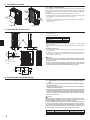
Confirmation of parts attached
In addition to this manual, the following parts are supplied with the outdoor unit.
They are used for grounding the S terminals of transmission terminal blocks TB3,
TB7. For details refer to “6. Electrical work”.
<PUMY-P112-140YKM>
<PUMY-P112-140VKM>
Grounding lead wire with a ferrite core for TB3
Grounding lead wire (× 2)
1. Safety precautions
► Before installing the unit, make sure you read all the “Safety precautions”.
► Please report to or take consent by the supply authority before connection to the system.
► Equipment complying with IEC/EN 61000-3-12
► PUMY-P·VKM series is designed for use in the residential, commercial
and light-industrial environment.
► PUMY-P·YKM series is designed as professional equipment.
Warning:
Describes precautions that must be observed to prevent danger of injury or
death to the user.
Grounding lead wire without a ferrite core for TB7
After installation work has been completed, explain the “Safety Precautions,” use, and
maintenance of the unit to the customer according to the information in the Operation
Manual and perform the test run to ensure normal operation. Both the Installation
Manual and Operation Manual must be given to the user for keeping. These manuals
must be passed on to subsequent users.
:Indicates a part which must be grounded.
Warning:
Carefully read the labels affixed to the main unit.
Caution:
Describes precautions that must be observed to prevent damage to the unit.
Warning:
• The unit must not be installed by the user. Ask a dealer or an authorized
technician to install the unit. If the unit is installed incorrectly, water leakage,
electric shock, or fire may result.
• This appliance is intended to be used by expert or trained users in shops, in
light industry and on farms, or for commercial use by lay persons.
• For installation work, follow the instructions in the Installation Manual and use
tools and pipe components specifically made for use with R410A refrigerant.
The R410A refrigerant in the HFC system is pressurized 1.6 times the pressure
of usual refrigerants. If pipe components not designed for R410A refrigerant are
used and the unit is not installed correctly, the pipes may burst and cause damage or injuries. In addition, water leakage, electric shock, or fire may result.
• The unit must be installed according to the instructions in order to minimize
the risk of damage from earthquakes, typhoons, or strong winds. An incorrectly installed unit may fall down and cause damage or injuries.
• The unit must be securely installed on a structure that can sustain its weight.
If the unit is mounted on an unstable structure, it may fall down and cause
damage or injuries.
• If the air conditioner is installed in a small room, measures must be taken to
prevent the refrigerant concentration in the room from exceeding the safety
limit in the event of refrigerant leakage. Consult a dealer regarding the appropriate measures to prevent the allowable concentration from being exceeded.
Should the refrigerant leak and cause the concentration limit to be exceeded,
hazards due to lack of oxygen in the room may result.
• Ventilate the room if refrigerant leaks during operation. If refrigerant comes
into contact with a flame, poisonous gases will be released.
• All electric work must be performed by a qualified technician according to
local regulations and the instructions given in this manual. The units must be
powered by dedicated power lines and the correct voltage and circuit breakers
must be used. Power lines with insufficient capacity or incorrect electrical
work may result in electric shock or fire.
• Use C1220 copper phosphorus, for copper and copper alloy seamless pipes,
to connect the refrigerant pipes. If the pipes are not connected correctly, the
unit will not be properly grounded and electric shock may result.
• Use only specified cables for wiring. The wiring connections must be made
securely with no tension applied on the terminal connections. Also, never
splice the cables for wiring (unless otherwise indicated in this document).
Failure to observe these instructions may result in overheating or a fire.
• The terminal block cover panel of the outdoor unit must be firmly attached. If
the cover panel is mounted incorrectly and dust and moisture enter the unit,
electric shock or fire may result.
• When installing or relocating, or servicing the air conditioner, use only the
specified refrigerant (R410A) to charge the refrigerant lines. Do not mix it with
any other refrigerant and do not allow air to remain in the lines.
If air is mixed with the refrigerant, then it can be the cause of abnormal high
pressure in the refrigerant line, and may result in an explosion and other
hazards.
The use of any refrigerant other than that specified for the system will cause
mechanical failure or system malfunction or unit breakdown. In the worst case,
this could lead to a serious impediment to securing product safety.
• Use only accessories authorized by Mitsubishi Electric and ask a dealer or an
authorized technician to install them. If accessories are incorrectly installed,
water leakage, electric shock, or fire may result.
• Do not alter the unit. Consult a dealer for repairs. If alterations or repairs are
not performed correctly, water leakage, electric shock, or fire may result.
• The user should never attempt to repair the unit or transfer it to another location. If the unit is installed incorrectly, water leakage, electric shock, or fire
may result. If the air conditioner must be repaired or moved, ask a dealer or
an authorized technician.
• After installation has been completed, check for refrigerant leaks. If refrigerant leaks into the room and comes into contact with the flame of a heater or
portable cooking range, poisonous gases will be released.
1. Safety precautions
1.1. Before installation
Caution:
• Do not use the unit in an unusual environment. If the air conditioner is installed
in areas exposed to steam, volatile oil (including machine oil), or sulfuric gas,
areas exposed to high salt content such as the seaside, or areas where the
unit will be covered by snow, the performance can be significantly reduced
and the internal parts can be damaged.
• Do not install the unit where combustible gases may leak, be produced, flow,
or accumulate. If combustible gas accumulates around the unit, fire or explosion may result.
• The outdoor unit produces condensation during the heating operation. Make
sure to provide drainage around the outdoor unit if such condensation is likely
to cause damage.
• When installing the unit in a hospital or communications office, be prepared for
noise and electronic interference. Inverters, home appliances, high-frequency
medical equipment, and radio communications equipment can cause the air
conditioner to malfunction or breakdown. The air conditioner may also affect
medical equipment, disturbing medical care, and communications equipment,
harming the screen display quality.
1.2. Before installation (relocation)
Caution:
• Be extremely careful when transporting the units. Two or more persons are
needed to handle the unit, as it weighs 20 kg or more. Do not grasp the packaging bands. Wear protective gloves to remove the unit from the packaging
and to move it, as you can injure your hands on the fins or other parts.
• Be sure to safely dispose of the packaging materials. Packaging materials, such
as nails and other metal or wooden parts may cause stabs or other injuries.
• The base and attachments of the outdoor unit must be periodically checked
for looseness, cracks or other damage. If such defects are left uncorrected,
the unit may fall down and cause damage or injuries.
• Do not clean the air conditioner unit with water. Electric shock may result.
• Tighten all flare nuts to specification using a torque wrench. If tightened too
much, the flare nut can break after an extended period and refrigerant can
leak out.
1.3. Before electric work
Caution:
• Be sure to install circuit breakers. If not installed, electric shock may result.
• For the power lines, use standard cables of sufficient capacity. Otherwise, a
short circuit, overheating, or fire may result.
• When installing the power lines, do not apply tension to the cables. If the
connections are loosened, the cables can snap or break and overheating or
fire may result.
• Be sure to ground the unit. Do not connect the ground wire to gas or water
pipes, lighting rods, or telephone grounding lines. If the unit is not properly
grounded, electric shock may result.
• Use circuit breakers (ground fault interrupter, isolating switch (+B fuse), and
molded case circuit breaker) with the specified capacity. If the circuit breaker
capacity is larger than the specified capacity, breakdown or fire may result.
1.4. Before starting the test run
Caution:
• Turn on the main power switch more than 12 hours before starting operation.
Starting operation just after turning on the power switch can severely damage
the internal parts. Keep the main power switch turned on during the operation
season.
• Before starting operation, check that all panels, guards and other protective
parts are correctly installed. Rotating, hot, or high voltage parts can cause
injuries.
• Do not touch any switch with wet hands. Electric shock may result.
• Do not touch the refrigerant pipes with bare hands during operation. The
refrigerant pipes are hot or cold depending on the condition of the flowing
refrigerant. If you touch the pipes, burns or frostbite may result.
• After stopping operation, be sure to wait at least five minutes before turning off
the main power switch. Otherwise, water leakage or breakdown may result.
1.5. Using R410A refrigerant air conditioners
Caution:
• Use C1220 copper phosphorus, for copper and copper alloy seamless pipes,
to connect the refrigerant pipes. Make sure the insides of the pipes are clean
and do not contain any harmful contaminants such as sulfuric compounds,
oxidants, debris, or dust. Use pipes with the specified thickness. (Refer to
page 6) Note the following if reusing existing pipes that carried R22 refrigerant.
- Replace the existing flare nuts and flare the flared sections again.
- Do not use thin pipes. (Refer to page 6)
• Store the pipes to be used during installation indoors and keep both ends of
the pipes sealed until just before brazing. (Leave elbow joints, etc. in their
packaging.) If dust, debris, or moisture enters the refrigerant lines, oil deterioration or compressor breakdown may result.
• Use ester oil, ether oil, alkylbenzene oil (small amount) as the refrigeration
oil applied to the flared sections. If mineral oil is mixed in the refrigeration
oil, oil deterioration may result.
• Do not use refrigerant other than R410A refrigerant. If another refrigerant is
used, the chlorine will cause the oil to deteriorate.
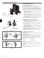
• Use the following tools specifically designed for use with R410A refrigerant.
The following tools are necessary to use R410A refrigerant. Contact your
nearest dealer for any questions.
Gauge manifold
Charge hose
Gas leak detector
Torque wrench
Tools (for R410A)
Flare tool
Size adjustment gauge
Vacuum pump adapter
Electronic refrigerant charging scale
• Be sure to use the correct tools. If dust, debris, or moisture enters the refrigerant lines, refrigeration oil deterioration may result.
• Do not use a charging cylinder. If a charging cylinder is used, the composition
of the refrigerant will change and the efficiency will be lowered.
2. Installation location
2.1. Refrigerant pipe
Refer to Fig. 4-1.
2.2. Choosing the outdoor unit installation location
• Avoid locations exposed to direct sunlight or other sources of heat.
• Select a location from which noise emitted by the unit will not inconvenience neighbors.
• Select a location permitting easy wiring and pipe access to the power source and
indoor unit.
• Avoid locations where combustible gases may leak, be produced, flow, or accumulate.
• Note that water may drain from the unit during operation.
• Select a level location that can bear the weight and vibration of the unit.
• Avoid locations where the unit can be covered by snow. In areas where heavy snow
fall is anticipated, special precautions such as raising the installation location or
installing a hood on the air intake must be taken to prevent the snow from blocking the air intake or blowing directly against it. This can reduce the airflow and a
malfunction may result.
• Avoid locations exposed to oil, steam, or sulfuric gas.
• Use the transportation handles of the outdoor unit to transport the unit. If the unit
is carried from the bottom, hands or fingers may be pinched.
(mm)
0
33
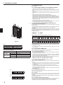
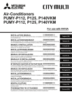
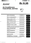
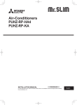
2.3. Outline dimensions (Outdoor unit) (Fig. 2-1)
Constraints on indoor unit installation
You should note that indoor units that can be connected to this outdoor unit are the
following models.
• Indoor units with model numbers 15-140 (PUMY-P112:15-125) can be connected.
Refer to the table 1 below for possible room, indoor unit combinations.
Verification
The rated capacity should be determined by observing the table below. The unit’s
quantities are limited as shown in the following table 2. For the next step, make
sure that the total rated capacity selected will stay in a range of 50% - 130% of the
outdoor unit capacity.
3
0+
105
1338
0
• PUMY-P112
• PUMY-P125
• PUMY-P140
6.3 - 16.2 kW
7.1 - 18.2 kW
8.0 - 20.2 kW
Table 1-1 (P*FY series (For Building Application indoor unit))
Indoor unit type P15 P20 P25 P32 P40 P50 P63 P71 P80 P100 P125 P140
Rated capacity
1.7 2.2 2.8 3.6 4.5 5.6 7.1 8.0 9.0 11.2 14.0 16.0
(Cooling) (kW)
225
600
0
37
Table 1-2 (M*Z series)
20
22
25
35
42
50
60
71
80
Indoor unit type 15
Rated capacity
1.5
2.0
2.2
2.5
3.5
4.2
5.0
6.0
7.1
8.0
(Cooling) (kW)
Combinations in which the total capacity of indoor units exceeds the capacity of the
outdoor unit will reduce the cooling capacity of each indoor unit below their rated
cooling capacity. Thus, combine indoor units with an outdoor unit within the outdoor
unit’s capacity, if possible.
Fig. 2-1
Table 2
Connectable indoor units quantities
PUMY-P112
1-9
PUMY-P125
1-10
PUMY-P140
1-12*
* Only when all the indoor units are 1.7 kW models, 12 indoor units can be connected
to 1 outdoor unit.
2.4. Connecting a PWFY Unit
When using a PWFY unit as an indoor unit, be aware of the following points
because the PWFY unit is different from other indoor units.
Table 3 PWFY unit specifications
Model
PWFY-P100VM-E-AU
Temp. range of
Heating
Outdoor temp.
–15 to 21°C (DB), –15 to 15°C (WB)
Inlet Water temp.
10 to 45°C
Temp. range of
Cooling
Outdoor temp.
–
Inlet Water temp.
–
2.4.1. Connection restrictions
• Only 1 PWFY-P100VM-E-AU can be connected. PWFY-P200VM-E-AU and PWFYP100VM-E-BU cannot be connected.
• The PWFY unit cannot be the only unit connected to an outdoor unit. Select an
outdoor unit so that the total rated capacity of the indoor units, excluding the PWFY
unit, is 50–100% of the outdoor unit capacity.
Limits for the total rated capacity of the indoor units when connecting a PWFY unit
• PUMY-P112 (1 PWFY unit + Non-PWFY units [6.3–12.5 kW])
• PUMY-P125 (1 PWFY unit + Non-PWFY units [7.1–14.0 kW])
• PUMY-P140 (1 PWFY unit + Non-PWFY units [8.0–15.5 kW])
2.4.2. Indoor unit specifications
When connecting a PWFY unit to a PUMY unit, the following specifications will
change.
• The PWFY unit can operate only in heating mode. The PWFY unit cannot operate
in cooling mode. However, the indoor units other than the PWFY unit can operate
in cooling mode.
• The other indoor units cannot operate at the same time as the PWFY unit.
• The operation of the PWFY unit has priority. When the PWFY unit is in the operation
mode, the other indoor units will stop.
• The temperature setting of the remote controller is the target value for the outlet
water temperature.
2.4.3. Switch settings (Fig. 2-2)
SW1
ON
1
2
3
4
5
6
7
8
9 10
2.4.4. Test run
SW4
ON
1
2
3
4
5
6
7
8
9 10
If the test run is carried out using the outdoor unit switches, the PWFY unit will
not operate. Carry out the test run using the PWFY unit switches or the remote
controller.
For information about carrying out the test run, refer to the data book or the service
manual for the PWFY unit.
2.4.5. Refrigerant collecting (Pump down)
Fig. 2-2
When connecting a PWFY unit to a PUMY unit, set DIP switches SW1-1, SW4-2, and
SW4-6 of the PWFY unit to ON.
Step 1 in the pump down procedure instructs the user to “operate all indoor units
in cooling mode”. However, the PWFY unit will not operate in cooling mode.
Operate all of the indoor units, excluding the PWFY unit, in cooling mode.
2. Installation location
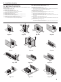
2.5. Ventilation and service space
2.5.2. When installing multiple outdoor units
2.5.1. When installing a single outdoor unit
Minimum dimensions are as follows, except for Max., meaning Maximum dimensions, indicated.
Refer to the figures for each case.
1Obstacles at rear only (Fig. 2-3)
2Obstacles at rear and above only (Fig. 2-4)
• Do not install the optional air outlet guides for upward airflow.
Leave 25 mm space or more between the units.
1 Obstacles at rear only (Fig. 2-9)
2 Obstacles at rear and above only (Fig. 2-10)
• No more than three units must be installed side by side. In addition, leave space as shown.
• Do not install the optional air outlet guides for upward airflow.
3 Obstacles at front only (Fig. 2-11)
∗ When using an optional air outlet guide, the clearance is 1000 mm or more.
4 Obstacles at front and rear only (Fig. 2-12)
3Obstacles at rear and sides only (Fig. 2-5)
4 Obstacles at front only (Fig. 2-6)
∗ When using an optional air outlet guide, the clearance is 1000 mm or more.
5 Single parallel unit arrangement (Fig. 2-13)
∗ When using an optional air outlet guide, the clearance is 500 mm or more.
∗ When using an optional air outlet guide installed for upward airflow, the clearance is 1000
mm or more.
5 Obstacles at front and rear only (Fig. 2-7)
∗ When using an optional air outlet guide, the clearance is 500 mm or more.
6 Multiple parallel unit arrangement (Fig. 2-14)
6 Obstacles at rear, sides, and above only (Fig. 2-8)
∗ When using an optional air outlet guide installed for upward airflow, the clearance is 1500
mm or more.
• Do not install the optional air outlet guides for upward airflow.
7 Stacked unit arrangement (Fig. 2-15)
• The units can be stacked up to two units high.
• No more than two stacked units must be installed side by side. In addition, leave space as shown.
00
x.5
1000
Ma
20
0
50
1
Fig. 2-3
0
Fig. 2-4
00
0
30
20
0
30
10
Fig. 2-5
00
x.5
Ma
Fig. 2-6
1500
25
0
0
15
0
50
25
0
0
10
0
Fig. 2-7
0
30
Fig. 2-8
00
x.3
Ma
Fig. 2-9
1500
15
00
0
50
0
Fig. 2-10
Fig. 2-11
Fig. 2-12
0
0
15
00
00
30
0
60
0
00
60
15
Fig. 2-13
150
50
20
00
1
1
50
10
0
50
0
50
Fig. 2-14
15
00
0
80
Fig. 2-15
2. Installation location
2.5.3. Windy location installation
When installing the outdoor unit on a rooftop or other location unprotected from the
wind, situate the air outlet of the unit so that it is not directly exposed to strong winds.
Strong wind entering the air outlet may impede the normal airflow and a malfunction
may result.
The following shows two examples of precautions against strong winds.
1Install an optional air guide if the unit is installed in a location where strong winds
from a typhoon, etc. may directly enter the air outlet. (Fig. 2-16)
A
AAir guide
B
2Position the unit so that the air outlet blows perpendicularly to the seasonal wind
direction, if possible. (Fig. 2-17)
BWind direction
Fig. 2-16
Fig. 2-17
3. Installing the outdoor unit
(mm)
• Be sure to install the unit in a sturdy, level surface to prevent rattling noises during
operation. (Fig. 3-1)
<Foundation specifications>
Foundation bolt
Thickness of concrete
Length of bolt
Weight-bearing capacity
M10 (3/8″)
120 mm
70 mm
320 kg
Max.30
• Make sure that the length of the foundation bolt is within 30 mm of the bottom
surface of the base.
• Secure the base of the unit firmly with four-M10 foundation bolts in sturdy locations.
Installing the outdoor unit
• Do not block the vent. If the vent is blocked, operation will be hindered and breakdown may result.
• In addition to the unit base, use the installation holes on the back of the unit to
attach wires, etc., if necessary to install the unit. Use self-tapping screws (ø5 × 15
mm or less) and install on site.
D
A M10 (3/8") bolt
B Base
C As long as possible.
D Vent
Min.475
600
Min.25 225
1050
225
25
330
370
600
Warning:
• The unit must be securely installed on a structure that can sustain its weight.
If the unit is mounted on an unstable structure, it may fall down and cause
damage or injuries.
• The unit must be installed according to the instructions in order to minimize
the risk of damage from earthquakes, typhoons, or strong winds. An incorrectly installed unit may fall down and cause damage or injuries.
Fig. 3-1
4. Installing the refrigerant piping
4.1. Precautions for devices that use R410A refrigerant
• Refer to page 3 for precautions not included below on using air conditioners
with R410A refrigerant.
• Use ester oil, ether oil, alkylbenzene oil (small amount) as the refrigeration
oil applied to the flared sections.
• Use C1220 copper phosphorus, for copper and copper alloy seamless pipes,
to connect the refrigerant pipes. Use refrigerant pipes with the thicknesses
specified in the table to the below. Make sure the insides of the pipes are clean
and do not contain any harmful contaminants such as sulfuric compounds,
oxidants, debris, or dust.
Warning:
hen installing or relocating, or servicing the air conditioner, use only the
W
specified refrigerant (R410A) to charge the refrigerant lines. Do not mix it with
any other refrigerant and do not allow air to remain in the lines.
If air is mixed with the refrigerant, then it can be the cause of abnormal high pressure in the refrigerant line, and may result in an explosion and other hazards.
The use of any refrigerant other than that specified for the system will cause
mechanical failure or system malfunction or unit breakdown. In the worst case,
this could lead to a serious impediment to securing product safety.
Indoor unit type
15-50
63-140
Liquid pipe
ø6.35 thickness 0.8 mm
ø9.52 thickness 0.8 mm
Gas pipe
ø12.7 thickness 0.8 mm
ø15.88 thickness 1.0 mm
• Do not use pipes thinner than those specified above.
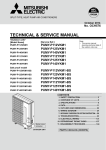
4. Installing the refrigerant piping
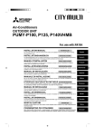
A+B+C+D+a+b+c+d+e 300 m
L = A+B+C+D+e 150 m
ℓ = B+C+D+e 30 m
H 50 m (Outdoor lower H 40 m)
h 15 m
A
L
H
C
b
e
D
c
d
A : Outdoor Unit
B : First Branch
C : Indoor unit
D : Cap
H
c
d
B, C, D
(mm)
e
f
È Liquid pipe
ø9.52
É Gas pipe
ø15.88
a, b, c, d, e, f
(mm)
Ë Model number
15, 20, 25, 32, 40, 50
63, 80, 100, 125, 140
È Liquid pipe
ø6.35
ø9.52
Í 4-Branching header
CMY-Y64-G-E
L
ℓ
É Gas pipe
ø15.88
É Gas pipe
ø12.7
ø15.88
Ì Branch kit model
CMY-Y62-G-E
A+a+b+c+d+e+f 300 m
L = A+f 150 m, ℓ = f 30 m
H 50 m (Outdoor lower H 40 m)
h 15 m
b
PUMY-P112-140
Ê Total capacity of indoor units
h
a
a
(mm)
È Liquid pipe
ø9.52
ℓ
B
A
A
Î 8-Branching header
CMY-Y68-G-E
* When connecting the CONNECTION KIT (PAC-LV11M-J) and an M-series indoor
unit, refer to the installation manual for the CONNECTION KIT when selecting the
pipe size and piping length.
h
4.2. Connecting pipes (Fig. 4-2)
Fig. 4-1 is a sample of piping system.
• Conduct sufficient anti-condensation and insulation work to prevent water dripping
from the refrigerant piping. (liquid pipe/gas pipe)
• Increase insulation depending on the environment where the refrigerant piping is
installed, or condensation may occur on the surface of the insulation material. (Insulation material Heat-resistant temperature: 120 °C, Thickness: 15 mm or more)
* When the refrigerant piping is used in locations subject to high temperature and
humidity such as in the attic, further addition of insulation may be required.
• To insulate the refrigerant piping, apply heat-resistant polyethylene foam between
the indoor unit and insulation material as well as to the net between the insulation
material filling all gaps.
(Condensation forming on the piping may result in condensation in the room or
burns when contacting the piping.)
• The indoor parts of the drain pipe should be wrapped with polyethylene foam insulation materials (specific gravity of 0.03, thickness of 9 mm or more).
• Apply thin layer of refrigerant oil to pipe and joint seating surface before tightening
flare nut. A
• Use two wrenches to tighten piping connections. B
• Use leak detector or soapy water to check for gas leaks after connections are
completed.
• Apply refrigerating machine oil over the entire flare seat surface. C
• Use the flare nuts for the following pipe size. D
Fig. 4-1
øA
.4
R0
90°± 0.5°
45°± 2°
0.8
-R
A Flare cutting dimensions
BFlare nut tightening torque
A (Fig. 4-2)
Copper pipe O.D.
(mm)
ø6.35
ø9.52
ø12.7
ø15.88
Fig. 4-2
Gas side
Liquid side
Flare dimensions
øA dimensions (mm)
8.7 - 9.1
12.8 - 13.2
16.2 - 16.6
19.3 - 19.7
Flare unt O.D.
(mm)
17
22
22
26
29
29
36
Tightening torque
(N·m)
14 - 18
34 - 42
34 - 42
49 - 61
68 - 82
68 - 82
100 - 120
Outdoor unit
112-140
ø15.88
ø9.52
1 Pipes must be connected starting from the indoor unit.
Flare nuts must be tightened with a torque wrench.
2 Flare the liquid pipes and gas pipes and apply a thin layer of refrigeration oil
(Applied on site).
• When usual pipe sealing is used, refer to Table 3 for flaring of R410A refrigerant
pipes.
The size adjustment gauge can be used to confirm A measurements.
Warning:
When installing the unit, securely connect the refrigerant pipes before starting
the compressor.
* To connect the CONNECTION KIT (PAC-LV11M-J), refer to the installation manual
for the CONNECTION KIT.
A
A Die
B Copper pipe
Table 3 (Fig. 4-3)
Copper pipe O.D. (mm)
Fig. 4-3
Indoor unit
63-140
ø15.88
ø9.52
• When bending the pipes, be careful not to break them. Bend radius of 100 mm to
150 mm is sufficient.
• Make sure the pipes do not contact the compressor. Abnormal noise or vibration
may result.
B (Fig. 4-2)
Copper pipe O.D.
(mm)
ø6.35
ø6.35
ø9.52
ø12.7
ø12.7
ø15.88
ø15.88
Pipe size (mm)
Pipe size (mm)
15-50
ø12.7
ø6.35
ø6.35
ø9.52
ø12.7
ø15.88
ø19.05
A (mm)
Flare tool for R410A
Flare tool for R22·R407C
Clutch type
0 - 0.5
1.0 - 1.5
0 - 0.5
1.0 - 1.5
0 - 0.5
1.0 - 1.5
0 - 0.5
1.0 - 1.5
0 - 0.5
1.0 - 1.5
4. Installing the refrigerant piping
4.3. Refrigerant piping (Fig. 4-4)
D
C
B
AFront piping cover
BPiping cover
CStop valve
DService panel
EBend radius : 100 mm - 150 mm
A E
Fig. 4-4
Remove the service panel D (three screws) and the front piping cover A (two screws)
and rear piping cover B (two screws).
1 Perform refrigerant piping connections for the indoor/outdoor unit when the outdoor
unit’s stop valve is completely closed.
2 Vacuum-purge air from the indoor unit and the connection piping.
3 After connecting the refrigerant pipes, check the connected pipes and the indoor
unit for gas leaks. (Refer to 4.4 Refrigerant pipe airtight testing method)
4 Vacuumize the refrigerant lines through the service port of the liquid and gas stop
valves. And then open the stop valves completely (for both the liquid and gas stop
valves). This will completely connect the refrigerant lines of the indoor and outdoor
units.
• If the stop valves are left closed and the unit is operated, the compressor and
control valves will be damaged.
• Use a leak detector or soapy water to check for gas leaks at the pipe connection sections of the outdoor unit.
• Do not use the refrigerant from the unit to purge air from the refrigerant
lines.
• After the valve work is completed, tighten the valve caps to the correct torque:
20 to 25 N·m (200 to 250 kgf·cm).
Failure to replace and tighten the caps may result in refrigerant leakage. In
addition, do not damage the insides of the valve caps as they act as a seal to
prevent refrigerant leakage.
5 Use sealant to seal the ends of the thermal insulation around the pipe connection
sections to prevent water from entering the thermal insulation.
4.4. Refrigerant pipe airtight testing method
AStop valve <Liquid side>
BStop valve <Gas side>
CService port
DOpen/Close section
ELocal pipe
FSealed, same way for gas side
GPipe cover
HDo not use a wrench here.
Refrigerant leakage may result.
IUse two wrenches here.
Fig. 4-5
(1) 1
2
Fig. 4-6
(2) 1
2
(1)Connect the testing tools.
• Make sure the stop valves A B are closed and do not open them.
• Add pressure to the refrigerant lines through the service port C of the liquid
stop valve A and the gas stop valve B.
(2)Do not add pressure to the specified pressure all at once; add pressure little by little.
1 Pressurize to 0.5 MPa (5 kgf/cm2G), wait five minutes, and make sure the pressure does not decrease.
2 Pressurize to 1.5 MPa (15 kgf/cm2G), wait five minutes, and make sure the
pressure does not decrease.
3 Pressurize to 4.15 MPa (41.5 kgf/cm2G) and measure the surrounding temperature and refrigerant pressure.
(3)If the specified pressure holds for about one day and does not decrease, the pipes
have passed the test and there are no leaks.
• If the surrounding temperature changes by 1°C, the pressure will change by
about 0.01 MPa (0.1 kgf/cm2G). Make the necessary corrections.
(4)If the pressure decreases in steps (2) or (3), there is a gas leak. Look for the source
of the gas leak.
4.5. Stop valve opening method
(1)Gas side (Fig. 4-6)
1 Remove the cap, pull the handle toward you and rotate 1/4 turn in a counterclockwise direction to open.
2 Make sure that the stop valve is open completely, push in the handle and rotate
the cap back to its original position.
(2)Liquid side (Fig. 4-7)
1 Remove the cap and turn the valve rod counterclockwise as far as it will go with
the use of a 4 mm hexagonal wrench. Stop turning when it hits the stopper.
(ø6.35: Approximately 4.5 revolutions) (ø9.52: Approximately 10 revolutions)
2 Make sure that the stop valve is open completely, push in the handle and rotate
the cap back to its original position.
AValve
BUnit side
CHandle
DCap
ELocal pipe side
FOpen position side
GService port
HWrench hole
IRefrigerant flow direction
Refrigerant pipes are protectively wrapped
• The pipes can be protectively wrapped up to a diameter of ø90 before or after connecting the pipes. Cut out the knockout in the pipe cover following the groove and
wrap the pipes.
Pipe inlet gap
• Use putty or sealant to seal the pipe inlet around the pipes so that no gaps remain.
(If the gaps are not closed, noise may be emitted or water and dust will enter the
unit and breakdown may result.)
Fig. 4-7
4. Installing the refrigerant piping
* The figure to the left is an example
only. The stop valve shape, service port
position, etc., may vary according to the
model.
* Turn section A only.
(Do not further tighten sections A and
B together. )
Precautions when using the charge valve (Fig.4-8)
Do not tighten the service port too much when installing it, otherwise, the valve core
could be deformed and become loose, causing a gas leak.
After positioning section B in the desired direction, turn section A only and tighten
it.
Do not further tighten sections A and B together after tightening section A.
CCharge hose
D Service port
Fig. 4-8
4.6. Additional refrigerant charge
Additional refrigerant charge
Refrigerant for the extended piping is not included in the outdoor unit when the unit is
shipped from the factory. Therefore, charge each refrigerant piping system with additional refrigerant at the installation site. In addition, in order to carry out service, enter
the size and length of each liquid pipe and additional refrigerant charge amounts in
the spaces provided on the “Refrigerant amount” plate on the outdoor unit.
Calculation of additional refrigerant charge
• Calculate the additional charge using the liquid pipe size and length of the extended piping and total capacity of connected indoor units.
• Calculate the additional refrigerant charge using the procedure shown to the right,
and charge with the additional refrigerant.
• For amounts less than 0.1 kg, round up the calculated additional refrigerant
charge.
(For example, if the calculated charge is 6.01 kg, round up the charge to 6.1 kg.)
<Additional Charge>
Calculation of refrigerant charge
Pipe size
Liquid pipe
+
ø6.35
(m) × 19.0 (g/m)
Pipe size
Liquid pipe
ø9.52
(m) × 50.0 (g/m)
+
Total capacity of
connected indoor units
Amount for the
indoor units
~ 8.0 kW
1.5 kg
8.1 ~ 16.0 kW
2.5 kg
16.1 kW ~
3.0 kg
Included refrigerant amount when shipped from the factory
Included refrigerant amount
4.8 kg
<Example>
Outdoor model : P125
Indoor 1: P63 (7.1 kW) A:ø9.52 30 m a : ø9.52 15 m
2: P40 (4.5 kW)
b : ø6.35 10 m
3: P25 (2.8 kW)
c : ø6.35 10 m
4: P20 (2.2 kW)
d : ø6.35 20 m
The total length of each liquid line is as follows:
ø9.52 : A + a = 30 + 15 = 45 m
ø6.35 : b + c + d = 10 + 10 + 20 = 40 m
The total capacity of connected indoor unit is as follows:
7.1 + 4.5 + 2.8 + 2.2 = 16.6
<Calculation example>
Additional refrigerant charge
19.0
50.0
+ 45 ×
+ 3.0 = 6.1 kg (rounded up)
40 ×
1000
1000
At the conditions
below:
5. Drainage piping work
Outdoor unit drainage pipe connection
When drain piping is necessary, use the drain socket or the drain pan (option).
Drain socket
Drain pan
P112-140
PAC-SG61DS-E
PAC-SH97DP-E
6. Electrical work
6.1. Caution
1 Follow ordinance of your governmental organization for technical standard related
to electrical equipment, wiring regulations and guidance of each electric power
company.
2 Wiring for control (hereinafter referred to as transmission line) shall be (5 cm or
more) apart from power source wiring so that it is not influenced by electric noise
from power source wiring. (Do not insert transmission line and power source wire
in the same conduit.)
3 Be sure to provide designated grounding work to outdoor unit.
4 Give some allowance to wiring for electrical part box of indoor and outdoor units,
because the box is sometimes removed at the time of service work.
5 Never connect the main power source to terminal block of transmission line. If
connected, electrical parts will be burnt out.
6 Use 2-core shield cable for transmission line. If transmission lines of different
systems are wired with the same multiplecore cable, the resultant poor transmitting and receiving will cause erroneous operations.
7 Only the transmission line specified should be connected to the terminal block
for outdoor unit transmission.
(Transmission line to be connected with indoor unit : Terminal block TB3 for
transmission line, Other : Terminal block TB7 for centralized control)
Erroneous connection does not allow the system to operate.
8 In case to connect with the upper class controller or to conduct group operation in
different refrigerant systems, the control line for transmission is required between
the outdoor units each other.
Connect this control line between the terminal blocks for centralized control. (2wire line with no polarity)
When conducting group operation in different refrigerant systems without connecting to the upper class controller, replace the insertion of the short circuit connector
from CN41 of one outdoor unit to CN40.
9 Group is set by operating the remote controller.
0 When connecting the CONNECTION KIT (PAC-LV11M-J) and an M-series indoor
unit, refer to the installation manual for the CONNECTION KIT.
6. Electrical work
<PUMY-P·VKM>
L
N
B1 B2
TB1
TB1B
B
A
M1
M2 S
M1
TB3
C
M2 S
F
TB7
D
<PUMY-P·YKM>
L1 L2 L3 N
TB1
A
6.2. Control box and connecting position of wiring
(Fig. 6-1)
E
E
M1
B1 B2
B
TB1B
M2 S
M1
M2 S
TB3
C
F
TB7
D
A : Power source
B : Power supply for branch box
C : Screw on the electrical component box
D : Transmission line
E : Screw on the electrical component box
F : Screw on the electrical component box
Caution:
Never connect the transmission line for the indoor unit or the central control
system transmission line to this terminal bed (TB1B). If the transmission lines
are connected, the indoor unit terminal block or centralized control terminal
block could be damaged.
Fig. 6-1
6.3. Wiring transmission cables
1 Types of control cables
1. Wiring transmission cables
• Types of transmission cables: Shielding wire CVVS or CPEVS or MVVS
• Cable diameter: More than 1.25 mm2
• Maximum wiring length: Within 200 m
2. M-NET Remote control cables
Kind of remote control cable
Cable diameter
1. Connect the indoor unit transmission line to transmission terminal block (TB3), or
connect the wiring between outdoor units or the wiring with the centralized control
system to the centralized control terminal block (TB7).
When using shielded wiring, connect shield ground of the indoor unit transmission
line to the screw (C or D) and connect shield ground of the line between outdoor
units and the central control system transmission line to the shield (S) terminal of
the centralized control terminal block (TB7) shield (S) terminal. In addition, in the
case of outdoor units whose power supply connector CN41 has been replaced
by CN40, the shield terminal (S) of terminal block (TB7) of the centralized control
system should also be connected to the screw C or D using attached lead wire.
2. Conduit mounting plates (ø27) are being provided. Pass the power supply and
transmission wires through the appropriate knock-out holes, then remove the
knock-out piece from the bottom of the terminal box and connect the wires.
3. Fix power source wiring to terminal box by using buffer bushing for tensile force
(PG connection or the like).
4. The terminal bed (TB1B) is for supplying power to the branch box (220 ~ 240 V.
max 6A).
Sheathed 2-core cable (unshielded) CVV
0.3 to 1.25 mm2 (0.75 to 1.25 mm2)*
When 10 m is exceeded, use cable with the
Remarks
same specifications as 1. Wiring transmission
cables.
* Connected with simple remote controller.
3. MA Remote control cables
Kind of remote control cable
Sheathed 2-core cable (unshielded) CVV
Cable diameter
0.3 to 1.25 mm2 (0.75 to 1.25 mm2)*
Remarks
Within 200 m
* Connected with simple remote controller.
2 Wiring examples
• Controller name, symbol and allowable number of controllers.
Name
Outdoor unit controller
Symbol
OC
Indoor unit controller
IC
Remote controller
RC
Allowable number of controllers
–
PUMY-P112 1 to 9 units per 1 OC
PUMY-P125 1 to 10 units per 1 OC
PUMY-P140 1 to 12 units per 1 OC
RC
Maximum of 12 controllers
(M-NET)
for 1 OC
MA
Maximum of 2 per group
Example of a group operation system with multiple outdoor units (Shielding wires and address setting are necessary.)
<Examples of Transmission Cable Wiring>
■ M-NET Remote Controller (Fig. 6-2)
■ MA Remote Controller (Fig. 6-3)
<Wiring Method and Address Settings>
a. Always use shielded wire when making connections between the outdoor unit (OC) and the indoor unit (IC), as well for all OC-OC, and IC-IC wiring intervals.
b. Use feed wiring to connect terminals M1 and M2 and the ground terminal on the transmission cable terminal block (TB3) of each outdoor unit (OC) to terminals M1, M2
and terminal S on the transmission cable block of the indoor unit (IC).
c. Connect terminals 1 (M1) and 2 (M2) on the transmission cable terminal block of the indoor unit (IC) that has the most recent address within the same group to the terminal
block on the remote controller (RC).
d. Connect together terminals M1, M2 and terminal S on the terminal block for central control (TB7) for the outdoor unit (OC).
e. The jumper connector CN41 on the control panel does not change.
f. Connect shield ground of the indoor units transmission line to the shield (S) terminal of (TB3) and also connect (S) terminal to screw C or D using attached lead wire.
Connect shield ground of the line between outdoor units and the central control system transmission line to the shield (S) terminal of (TB7).
g. Set the address setting switch as follows.
Unit
IC (Main)
Range
01 to 50
IC (Sub)
01 to 50
Outdoor Unit
51 to 100
M-NET R/C (Main)
M-NET R/C (Sub)
MA R/C
101 to 150
151 to 200
–
Setting Method
Use the most recent address within the same group of indoor units
Use an address, other than that of the IC (Main) from among the units within the same group of indoor units. This must
be in sequence with the IC (Main)
Use the most recent address of all the indoor units plus 50
*The address automatically becomes “100” if it is set as “01 - 50”.
Set at an IC (Main) address within the same group plus 100
Set at an IC (Main) address within the same group plus 150
Unnecessary address setting (Necessary main/sub setting)
h. The group setting operations among the multiple indoor units is done by the remote controller (RC) after the electrical power has been turned on.
i. When connecting a PWFY unit
• Do not perform the group settings for the PWFY unit and the indoor units.
• The PWFY unit and a Lossnay unit cannot be set to operate at the same time.
• Use a WMA remote controller for the PWFY unit.
For details, refer to the installation manual for the PWFY unit.
10
6. Electrical work
<Permissible Lengths>
1 M-NET Remote controller
• Max length via outdoor units:
L1+L2+L3+L4 and L1+L2+L3+L5 and L1+L2+L6+L7 500 m (1.25 mm2 or more)
• Max transmission cable length: L1 and L3+L4 and L3+L5 and L6 and L2+L6 and L7 200 m (1.25 mm2 or more)
• Remote controller cable length: ℓ1, ℓ2, ℓ2+ℓ3, ℓ4 10 m (0.5 to 1.25 mm2)
If the length exceeds 10 m, use a 1.25 mm2 shielded wire. The length of this section (L8) should be included in the calculation of the
maximum length and overall length.
2 MA Remote controller
• Max length via outdoor unit (M-NET cable): L1+L2+L3+L4 and L1+L2+L6+L7 500 m (1.25 mm2 or more)
• Max transmission cable length (M-NET cable): L1 and L3+L4 and L6 and L2+L6 and L7 200 m (1.25 mm2 or more)
• Remote controller cable length: m1 and m1+m2 +m3 and m1+m2+m3+m4 200 m (0.3 to 1.25 mm2)
■ M-NET Remote Controller
■ MA Remote Controller
L1
L1
N1
L2
TB5
M1 M2 S
M1 M2 S M1 M2 S
M1 M2 S
N3
L3
L4
L2
IC
(03)
TB7
C or D
M1 M2 S
TB5
M1 M2 S
TB5
M1 M2 S
IC
(07)
OC
(53)
M1 M2 S M1 M2 S
L6
(104)
RC
M1 M2 S
M1 M2 S
TB15
1 2
m4
A B
MA
MA
L4
C or D
(03)
IC
(04)
IC
(07)
TB15
TB5
M1 M2 S
1 2
TB5
TB15
M1 M2 S 1 2
TB15
TB5
M1 M2 S
1 2
M1 M2 S
A B
L7
System
controller
TB5
M1 M2 S
A B
IC
TB7
TB3
TB5
M1 M2 S
N4
TB7
IC
(06)
m2
TB15
1 2
A B
Power Supply
Unit
M1 M2 S
TB5
M1 M2 S
MA
L3
Power Supply
Unit
L7
TB5
TB15
M1 M2 S 1 2
m1
TB3
M1 M2 S
m2
TB15
1 2
A B
L5
L6
IC
(04)
C or D
(155)
RC
OC
(53)
TB5
M1 M2 S
IC
(05)
IC
(02)
m3
A B
(105)
RC
IC
(01)
m3
A B
TB7
TB3
TB5
(101)
RC
OC
(51)
m1
C or D
TB5
M1 M2 S
IC
(06)
m1
TB5
M1 M2 S
IC
(05)
N2
TB3
TB7
M1 M2 S M1 M2 S
IC
(02)
IC
(01)
(51)
OC
System
controller
M1 M2 S
TB7
A B
MA
M1 M2 S
Fig. 6-2
Fig. 6-3
A:Group
B:Group
C:Group
D:Shielded Wire
E:Sub Remote Controller
F : Screw on the electrical component box
( ): Address
A:Group
B:Group
C:Group
D:Shielded Wire
E:Sub Remote Controller
F : Screw on the electrical component box
( ): Address
6.4. Wiring of main power supply and equipment capacity
Schematic Drawing of Wiring (Example) (Fig. 6-4)
■ PUMY-P·VKM series
C
~/N 220/230/240 V 50 Hz
~/N 220 V 60 Hz
A
B
~/N 220/230/240 V 50 Hz
~/N 220 V 60 Hz
A
D
■ PUMY-P·YKM series
D
D
D
A:Switch (Breakers for Wiring and Current Leakage)
B:Outdoor Unit
C:Pull Box
D:Indoor Unit
3N~380/400/415 V 50 Hz
Fig. 6-4
Cross-sectional area of Wire for Main Power Supply and On/Off Capacities
Power Supply
Model
Outdoor Unit
P112-140V
P112-140Y
~/N 220/230/240 V 50 Hz
~/N 220 V 60 Hz
3N~380/400/415 V 50 Hz
Minimum Wire Cross-sectional area (mm2)
Main Cable
Branch
Ground
Breaker for Wiring *1
Breaker for Current Leakage
5.5(6)
–
5.5(6)
32 A
32 A 30 mA 0.1 sec. or less
1.5
–
1.5
16 A
16 A 30 mA 0.1 sec. or less
*1. A breaker with at least 3.0 mm contact separation in each poles shall be provided. Use non-fuse breaker (NF) or earth leakage breaker (NV).
Total operating current of the indoor unit
F0 = 16A or less *2
F0 = 25A or less *2
F0 = 32A or less *2
Minimum wire thickness (mm2)
Main Cable
Branch
Ground
1.5
1.5
1.5
2.5
2.5
2.5
4.0
4.0
4.0
Ground-fault interruper *1
20 A current sensitivity *3
30 A current sensitivity *3
40 A current sensitivity *3
Local switch (A)
Capacity
Fuse
16
16
25
25
32
32
Breaker for wiring
(NFB)
20
30
40
Apply to IEC61000-3-3 about max. permissive system impedance.
*1 The Ground-fault interrupter should support inverter circuit.
The Ground-fault interrupter should combine using of local switch or wiring breaker.
*2 Please take the larger of F1 or F2 as the value for F0.
F1 = Total operating maximum current of the indoor units × 1.2
F2 = {V1 × (Quantity of Type1)/C} + {V1 × (Quantity of Type2)/C} + {V1 × (Quantity of Type3)/C} + {V1 × (Quantity of Others)/C}
11
6. Electrical work
Indoor unit
Type 1
Type 2
Type 3
Others
PLFY-VBM, PMFY-VBM, PEFY-VMS,
PCFY-VKM, PKFY-VHM, PKFY-VKM
PEFY-VMA
PEFY-VMHS
Other indoor unit
V1
V2
18.6
2.4
38
13.8
0
1.6
4.8
0
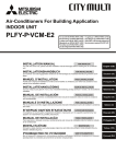
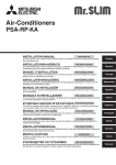
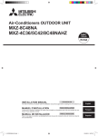
Sample chart
6000
C : Multiple of tripping current at tripping time 0.01s
Please pick up “C” from the tripping characteristic of the breaker.
600
G1
30 or less
100 or less
Wire thickness
1.5 mm2
2.5 mm2
4.0 mm2
Sample
Tripping Time [s]
<Example of “F2” calculation>
* Condition PEFY-VMS × 4 + PEFY-VMA × 1, C = 8 (refer to right sample chart)
F2 = 18.6 × 4/8 + 38 × 1/8
= 14.05
→ 16A breaker (Tripping current = 8 × 16A at 0.01s)
* 3 Current sensitivity is calculated using the following formula.
G1 = V2 × (Quantity of Type1) + V2 × (Quantity of Type2) + V2 × (Quantity of Type3) + V2 × (Quantity of Others)
+ V3 × (Wire length[km])
Current sensitivity
30 mA 0.1sec or less
100 mA 0.1sec or less
V3
48
56
66
60
10
1
0.1
0.01
1
2
3
4
6
8 10
20
C
Rated Tripping current (x)
1.
2.
3.
4.
5.
Use a separate power supply for the outdoor unit and indoor unit.
Bear in mind ambient conditions (ambient temperature,direct sunlight, rain water,etc.) when proceeding with the wiring and connections.
The wire size is the minimum value for metal conduit wiring. The power cord size should be 1 rank thicker consideration of voltage drops.
Make sure the power-supply voltage does not drop more than 10%.
Specific wiring requirements should adhere to the wiring regulations of the region.
Power supply cords of parts of appliances for outdoor use shall not be lighter than polychloroprene sheathed flexible cord (design 60245 IEC57). For example,
use wiring such as YZW.
6. Install an earth longer than other cables.
•
•
•
•
Warning:
Be sure to use specified wires to connect so that no external force is imparted to terminal connections. If connections are not fixed firmly, it may cause heating or fire.
Be sure to use the appropriate type of overcurrent protection switch. Note that generated overcurrent may include some amount of direct current.
Caution:
Some installation site may require attachment of an earth leakage breaker. If no earth leakage breaker is installed, it may cause an electric shock.
Do not use anything other than breaker and fuse with correct capacity. Using fuse and wire or copper wire with too large capacity may cause a malfunction
of unit or fire.
IMPORTANT
Make sure that the current leakage breaker is one compatible with higher harmonics.
Always use a current leakage breaker that is compatible with higher harmonics as this unit is equipped with an inverter.
The use of an inadequate breaker can cause the incorrect operation of inverter.
Never splice the power cable or the indoor-outdoor connection cable, otherwise it may result in a smoke, a fire or communication failure.
12
7. Test run
7.1. Before test run
► After completing installation and the wiring and piping of the indoor and
outdoor units, check for refrigerant leakage, looseness in the power supply
or control wiring, wrong polarity, and no disconnection of one phase in the
supply.
► Use a 500-volt M-ohm tester to check that the resistance between the power
supply terminals and ground is at least 1 MΩ.
► Do not carry out this test on the control wiring (low voltage circuit) terminals.
Warning:
Do not use the air conditioner if the insulation resistance is less than 1 MΩ.
Insulation resistance
After installation or after the power source to the unit has been cut for an extended
period, the insulation resistance will drop below 1 MΩ due to refrigerant accumulating
in the compressor. This is not a malfunction. Perform the following procedures.
1. Remove the wires from the compressor and measure the insulation resistance of
the compressor.
2. If the insulation resistance is below 1 MΩ, the compressor is faulty or the resistance dropped due the accumulation of refrigerant in the compressor.
3. After connecting the wires to the compressor, the compressor will start to warm
up after power is supplied. After supplying power for the times indicated below,
measure the insulation resistance again.
• The insulation resistance drops due to accumulation of refrigerant in the compressor. The resistance will rise above 1 MΩ after the compressor is warmed
up for four hours.
(The time necessary to warm up the compressor varies according to atmospheric
conditions and refrigerant accumulation.)
• To operate the compressor with refrigerant accumulated in the compressor, the
compressor must be warmed up at least 12 hours to prevent breakdown.
4. If the insulation resistance rises above 1 MΩ, the compressor is not faulty.
Caution:
• The compressor will not operate unless the power supply phase connection
is correct.
• Turn on the power at least 12 hours before starting operation.
- Starting operation immediately after turning on the main power switch can result
in severe damage to internal parts. Keep the power switch turned on during the
operational season.
► The followings must be checked as well.
• The outdoor unit is not faulty. LED on the control board of the outdoor unit flash
when the outdoor unit is faulty.
• Both the gas and liquid stop valves are completely open.
7.2. Test run
7.2.1. Using remote controller
Refer to the indoor unit installation manual.
• Be sure to perform the test run for each indoor unit. Make sure each indoor
unit operates properly following the installation manual attached to the unit.
• If you perform the test run for all indoor units at once, you cannot detect any
erroneous connection, if any, of the refrigerant pipes and the connecting
wires.
* The compressor operation is not available for 3 minutes at least after the
power is supplied.
• The compressor can emit noise just after turn on the power supply or in case
of low outside air temperature.
About the restart protective mechanism
Once the compressor stops, the restart preventive device operates so the compressor
will not operate for 3 minutes to protect the air conditioner.
7.3. Refrigerant collecting (Pump down)
Perform the following procedures to collect the refrigerant when moving the indoor
unit or the outdoor unit.
1 Turn off the circuit breaker.
2 Connect the low pressure side of the gauge manifold to the service port of the
gas side stop valve.
3 Close the liquid stop value.
4 Supply power (circuit breaker).
* Start-up of the indoor-outdoor communication takes about 3 minutes after the
power (circuit breaker) is turned on. Start the pump-down operation 3 to 4 minutes
after the power (circuit breaker) is turned ON.
5 Perform the test run for cooling operation (SW3-1: ON and SW3-2: OFF). The
compressor (outdoor unit) and ventilators (indoor and outdoor units) start operating
and test run for cooling operation begins. After the cooling operation has been
carried out for approximately five minutes, set the outdoor service switch SW2-4
(pump down switch) from OFF to ON.
* Do not continue to operate for a long time with the switch SW2-4 set to ON.
Make sure to switch it to OFF after pump down is completed.
* Only set the SW3-1 and SW3-2 to ON if the unit is stopped. However, even if the
unit is stopped and the SW3-1 and SW3-2 are set to ON less than 3 minutes after
the compressor stops, the refrigerant collecting operation can-not be performed.
Wait until compressor has been stopped for 3 minutes and then set the SW3-1
and SW3-2 to ON again.
7.2.2. Using SW3 in outdoor unit
Note:
In case of the test run from outdoor unit, all indoor units operate. Therefore,
you can not detect any erroneous connection of refrigerant pipes and the
connecting wires. If it aims at detection of any erroneous connection, be sure
to carry out the test run from remote controller with reference to “7.2.1 Using
remote controller.”
SW3-1
SW3-2
SW3-1
SW3-2
ON
OFF
ON
ON
Cooling operation
Heating operation
* After performing the test run, set SW3-1 to OFF.
• A few seconds after the compressor starts, a clanging noise may be heard from
the inside of the outdoor unit. The noise is coming from the check valve due to the
small difference in pressure in the pipes. The unit is not faulty.
The test run operation mode cannot be changed by DIP switch SW3-2 during
the test run. (To change the test run operation mode during the test run, stop
the test run by DIP switch SW3-1. After changing the test run operation mode,
resume the test run by switch SW3-1.)
6 Fully close the gas stop valve when the pressure reading on the gauge drops
0.05 - 0.00 MPa (approximately 0.5 - 0.0 kgf/cm2)
7 Stop the air conditioner operation (SW3-1: OFF and SW3-2: OFF). Set the outdoor
service switch SW2-4 from ON to OFF.
8 Turn off the power supply (circuit breaker).
* If too much refrigerant has been added to the air conditioner system, the pressure
may not drop to 0.5 kgf/cm2. If this occurs, use a refrigerant collecting device
to collect all of the refrigerant in the system, and then recharge the system with
the correct amount of refrigerant after the indoor and outdoor units have been
relocated.
Warning:
When pumping down the refrigerant, stop the compressor before disconnecting the refrigerant pipes. The compressor may burst and cause injury if any
foreign substance, such as air, enters the system.
13