1
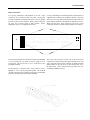
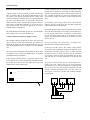
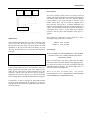
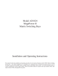
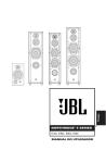
2033
Auxiliary Follower
Installation and Operating Instructions
The 2033 Auxiliary Follower can be used with all American Dynamics Matrix Switching Systems employing control code(s).
The 2033 Auxiliary Follower is used to provide a relay closure when an auxiliary or alarm command has been issued. Other
uses include the operation of panel displays showing called or alarmed camera sites.
The software/firmware furnished with this equipment is confidential to and is copyrighted by SENSORMATIC
ELECTRONICS CORPORATION. It is not to be copied or disclosed in any manner without the express written consent of
SENSORMATIC. The software/firmware is furnished to the purchaser under a license for use on a single system.
Information furnished by SENSORMATIC is believed to be accurate and reliable. However, no responsibility is assumed by
SENSORMATIC for its use; nor for any infringements of other rights of third parties which may result from its use. No
license is granted by implications or otherwise under any patent or patent rights of SENSORMATIC.
Copyright 2000 by Sensormatic. All Rights Reserved.
AMERICAN
DYNAMICS
The installation of this product should be made by qualified
service personnel and should conform to all local codes.
CAUTION
RISK OF ELECTRIC SHOCK
DO NOT OPEN
The lightning flash with arrowhead
symbol, within an equilateral
triangle, is intended to alert the
user to the presence of uninsulated
"dangerous voltage" within the
product's enclosure that may be of
sufficient magnitude to constitute a
risk of electric shock to persons.
!
CAUTION: TO REDUCE THE RISK OF ELECTRIC SHOCK,
DO NOT REMOVE COVERS (OR BACK) .
NO USER-SERVICEABLE PARTS INSIDE.
REFER SERVICING TO QUALIFIED SERVICE PERSONNEL
WARNING
!
The exclamation point within an
equilateral triangle is intended to
alert the user to the presence of
important operating and maintenance
(servicing) instructions in the
literature accompanying the product.
UNPACKING AND INSPECTION
To reduce the risk of fire or shock hazard, do
not expose this product to rain or moisture.
Unpack carefully. This is an electronic product and should
be handled as such. Compare the items received with the
packing list with your order.
This equipment has been tested and
found to comply with Part 15 of the
FCC Rules.
Be sure to save:
1. The shipping cartons and insert pieces. They are the
safest material in which to make future shipments of
the product.
2. The IMPORTANT SAFEGUARDS sheet.
3. These Installation and Operating Instructions.
Operation is subject to the
following two conditions: 1. This
device may not cause harmful
interference, and 2. This device
must accept any interference
received, including interference
that may cause undesired operation.
)
MAINTENANCE
User maintenance of this unit is limited to external cleaning
and inspection. For specific recommendations refer to the
IMPORTANT SAFEGUARDS sheet packaged with this product.
INSTALLATION AND SERVICE
If you require information during installation of this
product or if service seems necessary, contact the
Sensormatic Repair and Service Department at (800)
442-2225. You must obtain a Return Authorization Number
and shipping instructions before returning any product for
service.
Do not attempt to service this product yourself. Opening or
removing covers may expose you to dangerous voltages or
other hazards. Refer all servicing to qualified personnel.
QA301D
Table of Contents
Description ............................................................ 1
Features ................................................................. 1
Installation............................................................ 2
Mounting......................................................2
Auxiliary/Camera Select..............................2
DIP Switches................................................2
Connections
Relay Connections ..................................... 5
Data Line Connections............................... 6
Control Code Line Connections................. 6
Operation.............................................................. 7
Power Sources ...................................................... 7
Powering Up......................................................... 7
Appendix
Typical System Connections of 2033 Auxiliary Follower
Specifications ...........................................back page
DESCRIPTION
AA
AA
SELECT
1
5
DATA LINE
9
13
GROUP 1
POWER
DATA LINE
ABCDE
F
2A B
AB
AB
AB
17
AB
AB
ABCDE
F
19
ABCDE
F
B20
WS
AB
AB
10
AB
21
3
18
ABCDE
F
GROUP 2
A6B
AB
AB
4
AB
AB
AB
AB
25
11
7
22
AB
AB
AB
AB
AB
AB
26
AB
12
IN
14
AB
AB
AB
29
15
30
AB
AB
OUT
AB
AB
A B 16
31
27 G1 IN G1 OUT G2 IN G2 OUT
8
23
AB
24
28
AB
AB
32
AB
120V
60HZ
AB
Figure 1 - 2033 Auxiliary Follower
The 2033 filters the incoming codes for auxiliary commands
and camera group. The unit contains 32 addressable,
normally open relays. The 32 relays can be grouped in series
or in two alike groups of 16. Each of the two groups can
control 16 relays.
DESCRIPTION
The 2033 Auxiliary Follower provides relay closures which
correspond to an auxiliary call for a selected or switched
camera. The auxiliary function(s) (either 1, 2, or 3) can be
activated eithere manually from a keyboard, from a system
tour, or from an alarm. The Auxiliary Follower can address
one to 1024 cameras in groups of 16.
FEATURES
The 2033 is typically used where a high concentration of
auxiliary devices (i.e., electronic door switches or auxiliary
lighting) need to be controlled, but where pan/tilt functions
are not necessary. Note: The use of the 2033 does not negate
the use of the pan/tilt control at a remote site.
The 2033 Alarm Responder has the following features:
☛ SCREW TERMINAL WIRE CONNECTORS
☛ LED INDICATOR FOR “VALID" CODE
Additionally, the 2033 can provide contact closures
coordinated with an alarm callup. The contact closure occurs
when the corresponding camera is automatically placed into
alarm from an external device.
☛ LED POWER INDICATOR
☛ DIP SWITCH SELECTION FOR CAMERA GROUP
AND AUXILIARY
☛ COMPATIBLE WITH EITHER DATA LINE OR
CONTROL CODE
The 2033 receives data from either a LAN output of a 1995, a
DATA LINE output of a 1996, or a Control Code output of a
Matrix Switching System. If the 2033 operates via control
code, a dip switch located on the 2033’s main printed circuit
board, is used to select the Control Code mode.
☛ UNIVERSAL MOUNT CABINET
1
INSTALLATION
For optimum performance, the 2033 should be located near
the Switching Systems (1995, 1996, 2050, or 1024) or near
the Control Code Line of a Matrix Switching System. Avoid
heat sources or poorly ventilated racks.
IF YOU ENCOUNTER ANY PROBLEMS
OPERATING THIS UNIT, OR NEED TECHNICAL
ASSISTANCE, CALL OUR SERVICE CENTER.
DIP Switches
within the United States 1-800-442-2225
outside the United States (845) 624-7640
DIP switches, located on the rear panel, are used in the 2033
to determine auxiliary settings and camera group selections.
The 2033 Auxiliary Follower provides relay closures only;
they are not intended to supply power (see the relay contact
on page 5). The relay closures on the 2033 are activated by
an auxiliary call. The DIP switches on the 2033 are used to
determine the auxiliary setting (1, 2, or 3) and the camera
group (1 - 1024 in groups of 16; i.e., 1-16, 17-32, 33-48
...977-992, 993-1024). The two top DIP switches (1&2) set
the GROUP 1 relays. The lower two DIP switches (3&4) set
the GROUP 2 relays. Each relay group contains an auxiliary
setting and a camera setting. See the illustration below.
INSTALLATION
The Universal cabinet of a 2033 Auxiliary Follower may be
surface or rack mounted in any convenient location with
adequate ventilation. For proper ventilation allow at least
three feet (1m) form the rear of the racks to any wall and one
EIA rack height (1 3/4 inches) between units.
Mounting
The 2033 is shipped with mounting ears flush with the front
panel, and can be mounted to the front of a standard 19-inch
rack.
The first and third switches are programmed to correspond to
the desired auxiliary (1, 2, or 3). For auxiliary settings see
Table 2, page 4. The second and fourth switches are
programmed to correspond to the desired camera block (1 1024). For camera settings see Table 1, page 3.
The mounting ears of the 2033 can also be placed such that
they are flush with the rear panel. This allows the 2033 to be
mounted to the rear of a rack equipped with mounting
channels.
Note:
Group 1 and Group 2 can be set to two different
auxiliary and camera groups, if desired.
The unit can also be surface mounted. Mount the ears so that
they are either up or down flush with the top and bottom
covers of the unit.
DIP Switch 1 - Auxiliary Setting
Group 1 Relay
DIP Switch 2 - Camera Setting
DIP Switch 3 - Auxiliary Setting
Group 2 Relay
DIP Switch 4 - Camera Setting
A
GROUP 1
PWR
SELECT
ON
2
3
4
5
6
7
8
9
10
11
12
13
A B
A B
A B
A B
A B
A B
A B
A B
A B
A B
A B
A B
A B
20
21
A B
A B
14
15
16
IN
OFF
ABCDEF
ON
OFF
DATA
GROUP 2
DATA LINE
1
17
18
19
22
23
24
25
26
27
28
A B
A B
A B
29
30
31
32
A B
A B
A B
A B
1
OUT
ABCDEF
ON
OFF
A B
A B
A B
A B
A B
A B
A B
A B
A B
A B
ABCDEF
G1 IN G1 OUT G2 IN G2 OUT
ON
OFF
ABCDEF
A B
BWS
2
A B
A B
A B
120V
60Hz
CONNECTIONS
CONNECTIONS
Relay Connections
Two groups (GROUP 1 and GROUP 2) of four 12-pin
connectors are provided on the rear panel. Each group
provides connection for double pole relays. The two groups
provide 32 pairs of relay closures. Relay contact ratings are
24 VAC, 0.6 A resistive load, 2 Amp, 30VDC. Power
through the relays is not supplied by the 2033.
For ease of attaching to external equipment, each connector is
supplied with a mating screw terminal connector, Insert the
three wires of a relay pair and shield into the slots of the rear
panel mating connectors and tighten the hold-down screws.
When all lines have been connected, insert the 12-pin
connectors into the rear panel mating terminals. See Figure 2.
Group 1
A
GROUP 1
PWR
SELECT
ON
2
3
4
5
6
7
8
9
10
11
12
13
A B
A B
A B
A B
A B
A B
A B
A B
A B
A B
A B
A B
A B
20
21
A B
A B
14
15
16
IN
OFF
ABCDEF
ON
OFF
DATA
GROUP 2
DATA LINE
1
17
18
19
22
23
24
25
26
27
28
A B
A B
A B
29
30
31
32
A B
A B
A B
A B
1
OUT
ABCDEF
ON
OFF
A B
A B
A B
A B
A B
A B
A B
A B
A B
A B
ABCDEF
G1 IN G1 OUT G2 IN G2 OUT
ON
120V
60Hz
OFF
ABCDEF
A B
BWS
A B
A B
A B
Group 2
The relay connections to the unit must be made with shielded,
2-wire twisted pair (22 AWG or heavier gauge wire or
equivalent). The shield wire is to be connected to the
grounding terminal.
The lower right connector on the rear of the of the 2033
contains the common input and output connections for each
group. The four sections of the connector are labeled with the
group number G1 IN, G1 OUT, G2 IN, and G2 OUT, an A,
B, and ground. These connections are provided for easy
cascading to additional 2033’s.
Each connector is labeled with a relay number, from 1
through 32, an A, a B, and a ground symbol. The A and B
on each connector are the contacts for one side of each double
pole relay. The ground pin is provided for shielding.
HOLD DOWN SCREWS
A
B
A
B
A
B
A
B
R
TO
EC
N
ON
TC
ION
R
E
CT
E
INS
DIR
IS
TH
Figure 2 - Typical 12-Pin Connector
5
CONNECTIONS
Control Code lines must be terminated in 120 ohms. Check
the last unit on each line to ensure that 120-ohm termination
is present. Intermediate units on a Control code line must not
have 120-ohm termination. To remove the termination of the
2033 code line, jumper J32 must be removed from the main
PCB.
Data Line Connections (1995 or 1996)
A DATA LINE is connected from the DATA LINE OUT
BNC on a Matrix Bay to the DATA LINE IN BNC on the
rear panel of the Auxiliary/Alarm Follower. (Older 1995
systems used the term LAN IN/OUT). Use a good grade RG59 video cable (Belden 8241 or equivalent). The DATA
LINE OUT BNC on the Auxiliary/Alarm Follower must be
fitted with a 75-ohm BNC terminator, or if used to loop to
other DATA LINE controlled equipment, it must be
terminated at the end of the run.
In seitching systms using Control Code, the Auxiliary
Follower must be connected to code line that contains the
cameras and monitor to be followed.
For 1650A operation, there can be a maximum of four control
lines. The first control line is for monitors 1-8 and cameras 164. The second control line is fo monitors 1-8 and cameras
65-128. The third control line is for monitors 9-16 and
cameras 1-64. The fourth control line is for monitors 9-16 and
cameras 65-128.
The LED labeled DATA LINE on the 2033 will illuminate
when a valid code is received on the Data line.
Control Code Line Connections (1650A or 2150)
The terminal connector located at the lower left side of the
2033 is used for Control Code connections. The connector is
labeled B, W, and S. The B is for the BLACK code wire, the
W is for the WHITE code wire, and the S is for the SHIELD
wire.
For 2150 Systems, one control line is available for a
maximum of 32 cameras and five monitors.
Code Lines are NEC Class 2, low voltage circuits. Where
local codes permit, installation conduit is not required. Avoid
installation near high voltage sources or other potential
interference sources. Control Code lines must be terminated
in 120 ohms. Check the final code-controlled unit on each
code line and, if a 120 ohm termination is not present, add
one.
The Control Line connections to the Auxiliary Follower must
be shielded, 2-wire twisted pair (Belden 8760, for Plenum,
use Belden 88760 or equivalent).
If the Auxiliary/Alarm Follower is used with Control Code,
remove the top cover of the unit and locate the DIP switch on
the printed circuit board. Turn the eighth switch ON. This
enables the use of the Control Code.
Up to three Control devices may be “daisy-chained” on a
single code line. When devices are daisy-chained,
intermediate devices must not terminate the control line. Be
sure to check that the intermediate equipment does not
contain a 120 ohm terminating resistor. If it does, remove it.
See Figures 3 and 4 for “STAR” and “DAISY-CHAIN”
configurations.
120 ohm Termination Jumper
J32
ON
OFF
12345678
Dip Switch
02033
32
B W S
Power Cord
T
22033
032
B W S
T
22033
032
B W S
T
OTHER CODE
LINES
CODE
DISTRIBUTOR
T = 120 OHM TERMINATION
Figure 4 - Code "Star" Configuration"
6
OPERATION
2033
B W S
2033
B W S
2033
B W S
Power Sources
The 2033 Auxiliary Follower does not contain an On/Off
Switch. The socket outlet shall be located near the equipment
and shall be readily accessible. The 120 V units are supplied
with a pendant 3-wire cord and plug for mating to the
primary source outlet. The 230 V units are supplied with a
Euro style IEC 320 type inlet. A suitable detachable cord
should be connected between the IEC 320 inlet and the power
source. The cord should conform to all national and local use
code requirements. There is a green LED power indicator,
located on the rear panel, that illuminates when power is
applied.
T
OTHER CODE
LINES
CODE
DISTRIBUTOR
T = 120 OHM
Figure 4 - Code "Daisy Chain" Configuration
2033 models are configured for 120V, 50/60 Hz or 230V,
50/60Hz, primary power source, as follows:
OPERATON
After completing the Data Line (or Code) connections, plug
in the power cord. When the 2033 receives a valid code
through the Data Line inputs, the green Data Line LED
illuminates. If the green code LED is flickering, the code
lines may be backwards. Try reversing the black and white
code lines.
AD2033: 120V, 50/60Hz
AD2033-1: 230V, 50/60Hz
Powering Up
DO NOT CONNECT THE EQUIPMENT TO THE POWER
SOURCE UNTIL ALL CONNECTIONS HAVE BEEN
PROPERLY MADE.
CAUTION - Due to the presence of noninsulated components with hazardous voltages,
the following internal adjustments should be
performed by qualified service personnel only.
Make all connections to the 2033, (Data Lines, and Relay
connections) and set the DIP switches before applying power.
If a valid code is being received, the green DATA LED will
illuminate and glow steadily. If it flickers there may be a
problem with the Control Input line.
If the DATA LINE LED does not illuminate, check for
proper operation of the System (1650, 1995, 1996, or 2150).
Check all your connections. If all the connections are as they
should be, and the 2033 still does not operate properly,
unplug the 2033, remove the top cover, and check the DIP
switch settings. Refer to the DIP switch illustration on page 6.
There are no user servicable parts. For specific
recommendations, refer to IMPORTANT SAFEGUARDS
FOR COMMERCIAL VIDEO PRODUCTS.
If connected to a 1995 or 1996 System, all the DIP switches
should be in the OFF position. If connected to a 1650 or a
2150 System, the position for the eighth DIP switch should be
in the ON position.
7
APPENDIX
2033 AUXILIARY FOLLOWER
Camera # 1
Channel B
Channel A
1
A B
2
3
4
A B
A B
A B
DATALINE/LAN
FROM CPU
(1995,1996)
Selects Auxiliary # and
Camera Group # to Follow
SELECT
GROUP 1
PWR
DATA
GROUP 2
ON
5
ABCDEF
6
9
7
10
8
13 11
14
DATA LINE
15
12
ON
ABCDEF
A B
A B
A B
18
A B
A B
2119
A B
A B
22 20
A B
A B
25
23
A B
A B
26
24
A B
A B
29 27
A B
30
A B
1
28
31
OUT
32
ABCDEF
A B
OFF
ON
A B
17
OFF
ON
16
IN
OFF
A B
A B
A B
A B
A B
A B
A B
A B
A B
A B
A B
A B
A B
A B
A B
G1 IN G1 OUT G2 IN G2 OUT
ABCDEF
OFF
A B
BWS
A B
A B
A B
CONTROL CODE INPUT
(1600, 1650A, 2150)
G1 IN G1 OUT G2 IN G2 OUT
A B
A B
A B
A B
Channel B
Channel A
DATA LINE/LAN OUT to
Additional 2033's, Bays,
or 75-ohm Terminator
TYPICAL SYSTEM CONNECTIONS
2033 AUXILIARY FOLLOWER
RELAY
ALARMS
-CODE-
CAMERAS
1
3
5
7
9
11
13
15
17
19
21
23
25
27
29
31
2
4
6
8
10
12
14
16
18
20
22
24
26
28
30
32
MONITORS
1
2
1
3
4
2
5
KEYBOARDS
3
2
3
4
5
RS232 PORTS
2150
BWS
RS-232
1
MONITOR
MONITOR
MONITOR
MONITOR
8
6
4
2
7
5
3
1
2
3
4
A
A
A
A
A
A
A
A
B
B
B
B
B
B
B
B
O
U
T
O
U
T
O
U
T
O
U
T
O
U
T
O
U
T
O
U
T
O
U
T
J1
OUT
B
W
S
1650
1650A
from 1600, 1650A, 1700, or 2150 Systems
BWS
SELECT
GROUP 1
PWR
DATA
GROUP 2
ON
5
ABCDEF
6
9
7
10
8
13 11
14
12
ABCDEF
A B
A B
A B
18
A B
A B
2119
A B
A B
22 20
A B
A B
25
23
A B
A B
26
24
A B
A B
29 27
A B
30
A B
28
1
31
OUT
32
ABCDEF
A B
OFF
ON
A B
17
OFF
ON
16
IN
OFF
ON
DATA LINE
15
A B
A B
A B
A B
A B
A B
A B
A B
A B
A B
A B
A B
A B
A B
A B
G1 IN G1 OUT G2 IN G2 OUT
ABCDEF
OFF
BWS
A B
A B
A B
A B
2033
DATALINE OUT to
additional 2033's or 75-ohm
terminator
TYPICAL SYSTEM CONNECTIONS
2033 AUXILIARY FOLLOWER
SELECT
5
ABCDEF
ON
GROUP 1
6
8
OFF
ABCDEF
A B
ABCDEF
17
20
A B
A B
A B
A B
A B
A B
A B
9
12
7
A B
A B
10
A B
13 11
16
A B
A B
DATA LINE
15
14
IN
A B
A B
A B
1
ON
PWR
OFF
DATA
18
2119
24
22
25
23
28
26
29 27
32
30
31
OUT
ON
GROUP 2
A B
OFF
A B
A B
A B
A B
A B
A B
A B
A B
A B
A B
A B
A B
A B
A B
A B
G1 IN G1 OUT G2 IN G2 OUT
ABCDEF
ON
OFF
A B
BWS
A B
A B
A B
2033
BW S
CODE LED
WBS
J1
1691
18 AWG SHIELDED
TWISTED PAIR BELDEN
8760 OR EQUIVALENT
W
B
S
S W B A AC
C
5604-0109-01
12 VOLTS AC
10 VA
RS-232
1
MONITOR
MONITOR
MONITOR
MONITOR
8
6
4
2
7
5
3
1
2
3
A
A
A
A
A
A
A
A
B
B
B
B
B
B
B
B
O
U
O
U
O
U
O
U
T
O
U
T
O
U
T
O
U
T
O
U
T
T
T
T
J1
OUT
Showing a 1650, 1650A System
TYPICAL SYSTEM CONNECTIONS
2033 AUXILIARY FOLLOWER with 1650
RS-232
1
SYNC
VIP
MONITOR
MONITOR
MONITOR
MONITOR
8
6
4
2
7
5
3
1
2
1
A
A
A
A
A
A
A
A
B
B
B
B
B
B
B
B
O
U
T
O
U
T
O
U
T
O
U
T
O
U
T
O
U
T
O
U
T
O
U
T
3
3
4
5
7
J1
OUT
1650: MONITORS 1 - 8
2
4
6
8
POWER AND SIGNALS
VIP
CAMERA
4
J1
OUT
B
W
S
CAMERA
CAMERA
CAMERA
CAMERA
CAMERA
57
49
41
33
25
17
9
1
3
58
50
42
34
26
18
10
2
5
59
51
43
35
27
19
11
3
7
60
52
44
36
28
20
12
4
2
61
53
45
37
29
21
13
5
4
62
54
46
38
30
22
14
6
6
63
55
47
39
31
23
15
7
8
64
56
48
40
32
24
16
8
CAMERA
J1
OUT
CAMERA
1
VIP
4
CAMERA
CAMERA
CAMERA
CAMERA
CAMERA
CAMERA
CAMERA
1650: CAMERAS 1 - 64
CAMERA
1
121
113
105
97
89
81
73
65
3
122
114
106
98
90
82
74
66
5
123
115
107
99
91
83
75
67
7
124
116
108
100
92
84
76
68
2
125
117
109
101
93
85
77
69
4
126
118
110
102
94
86
78
70
6
127
119
111
103
95
87
79
71
8
128
120
112
104
96
88
80
72
1650: CAMERAS 65-128
B
W
S
BWS
SELECT
ON
GROUP 1
PWR
ABCDEF
2
53
6
4
9 7
10
8
13
11
DATA LINE
14 12
15
ON
ON
OFF
ON
16
IN
ABCDEF
A B
A B
17
OFF
DATA
GROUP 2
1
OFF
A B
A B
A B
A B
1921
18
A B
A B
22
20
A B
A B
2325
A B
A B
2426
A B
A B
27
29
A B
30
A B
28
1
31OUT
32
2033: CAMERAS 65-128
ABCDEF
A B
A B
A B
A B
A B
A B
A B
A B
A B
A B
A B
A B
A B
A B
A B
A B
G1 IN G1 OUT G2 IN G2 OUT
ABCDEF
OFF
A B
BWS
A B
A B
A B
BWS
SELECT
ON
GROUP 1
PWR
ON
OFF
DATA
ON
GROUP 2
ABCDEF
1
2
53
6
4
9 7
10
8
13
11
DATA LINE
14 12
15
OFF
A B
A B
17
A B
A B
18
A B
A B
1921
A B
A B
22
20
A B
A B
2325
A B
A B
2426
A B
A B
29
27
A B
30
A B
28
1
31OUT
ABCDEF
A B
OFF
ON
16
IN
ABCDEF
A B
A B
A B
A B
A B
A B
A B
A B
A B
A B
A B
A B
A B
A B
A B
G1 IN G1 OUT G2 IN G2 OUT
ABCDEF
OFF
BWS
A B
A B
A B
A B
32
2033: CAMERAS 1 - 64
DECLARATION OF CONFORMITY
According to ISO/IEC Guide 22 and EN45014
Manufacturer’s Name:
Sensormatic Electronics Corporation
Manufacturer’s Address:
1 Blue Hill Plaza
2nd Floor
Pearl River, New York, 10965 USA
Declares, that the product listed below:
Name/Type:
Auxiliary Follower
Model Number:
AD2033-1
complies with all applicable directives as demonstrated by conformance to the following Product Specifications:
Safety:
EN 60950: 1992
EMC:
EN 50130-4: 1995
EN 55022: 1994 , Class B
EN 61000-3-2: 1995
EN 61000-3-3: 1995
EN 61000-4-2: 1995
EN 61000-4-3: 1996
EN 61000-4-4: 1995
EN 61000-4-5: 1995
EN 61000-4-6: 1996
EN 61000-4-11: 1994
Supplementary Information:
The products herewith comply with the requirements of the Low Voltage Directive, 73/23/EEC as amended by
93/68/EEC, and the EMC Directive, 89/339/EEC as amended by 93/68/EEC.
Pearl River, NY, USA
15 December, 2000
Harold D. Johnson, Ph.D.
Director of Engineering
European Contact: Sensormatic France S.A.
7, rue Alexis de Tocqueville, Parc de Haute Technologie, 92183 ANTONY CEDEX
SPECIFICATIONS
Electrical Ratings:
AD2033
AD2033-1
120 VAC, 50/60Hz, 15 W
230 VAC, 50/60Hz, 125 mA
Relay Contact Ratings: 0.6 A, 24 VAC; 2 A, 30 VDC
Mounting:
Surface Mount or Rack Mount
Weight:
7 lbs (1.4 kg)
Finish:
Shadow Gray
Dimensions:
17" W x 3.5" H x 8" D (432 x 89 x 203 mm)
Sensormatic Video Systems Divsion
One Blue Hill Plaza
Pearl River, New York 10965
(845) 624-7600
Technical Support Center: 800-442-2225
FAX: (845) 624-7685
8000-1815-01, Revision A
December, 2000
Printed in USA