1
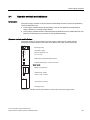
Preface
SIMATIC S7-400 S7-400 Automation System Module Data
SIMATIC
S7-400
S7-400 Automation System Module
Data
Reference Manual
1
General specifications
______________
2
Rack
______________
3
Power supply modules
______________
4
Digital modules
______________
5
Analog modules
______________
6
Interface modules
______________
7
S5 interface IM 463-2
______________
PROFIBUS DP master
interface IM 467/IM 467 FO
8
______________
Cable duct and fan
subassemblies
9
______________
10
RS 485 repeater
______________
Parameter sets of signal
modules
A
______________
Diagnostic data of signal
modules
B
______________
C
Accessories and spare parts
______________
This manual is part of the documentation
package 6ES7498-8AA05-8BA0
Directive on handling
electrostatic sensitive
devices (ESD)
D
______________
E
List of abbreviations
______________
Edition 09/2009
A5E00850736-06
Legal information
Legal information
Warning notice system
This manual contains notices you have to observe in order to ensure your personal safety, as well as to prevent
damage to property. The notices referring to your personal safety are highlighted in the manual by a safety alert
symbol, notices referring only to property damage have no safety alert symbol. These notices shown below are
graded according to the degree of danger.
DANGER
indicates that death or severe personal injury will result if proper precautions are not taken.
WARNING
indicates that death or severe personal injury may result if proper precautions are not taken.
CAUTION
with a safety alert symbol, indicates that minor personal injury can result if proper precautions are not taken.
CAUTION
without a safety alert symbol, indicates that property damage can result if proper precautions are not taken.
NOTICE
indicates that an unintended result or situation can occur if the corresponding information is not taken into
account.
If more than one degree of danger is present, the warning notice representing the highest degree of danger will
be used. A notice warning of injury to persons with a safety alert symbol may also include a warning relating to
property damage.
Qualified Personnel
The product/system described in this documentation may be operated only by personnel qualified for the specific
task in accordance with the relevant documentation for the specific task, in particular its warning notices and
safety instructions. Qualified personnel are those who, based on their training and experience, are capable of
identifying risks and avoiding potential hazards when working with these products/systems.
Proper use of Siemens products
Note the following:
WARNING
Siemens products may only be used for the applications described in the catalog and in the relevant technical
documentation. If products and components from other manufacturers are used, these must be recommended
or approved by Siemens. Proper transport, storage, installation, assembly, commissioning, operation and
maintenance are required to ensure that the products operate safely and without any problems. The permissible
ambient conditions must be adhered to. The information in the relevant documentation must be observed.
Trademarks
All names identified by ® are registered trademarks of the Siemens AG. The remaining trademarks in this
publication may be trademarks whose use by third parties for their own purposes could violate the rights of the
owner.
Disclaimer of Liability
We have reviewed the contents of this publication to ensure consistency with the hardware and software
described. Since variance cannot be precluded entirely, we cannot guarantee full consistency. However, the
information in this publication is reviewed regularly and any necessary corrections are included in subsequent
editions.
Siemens AG
Industry Sector
Postfach 48 48
90026 NÜRNBERG
GERMANY
A5E00850736-06
Ⓟ 09/2009
Copyright © Siemens AG 2009.
Technical data subject to change
Preface
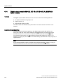
Purpose of this manual
The information contained in this manual can be used as a reference for operating, for
descriptions of the functions, and for the specifications of the signal modules, power supply
modules and interface modules of the S7-400.
How to configure, assemble and wire these modules in an S7-400 system is described in the
installation manuals for each system.
Basic knowledge required
This manual requires general knowledge of automation engineering.
In addition, you are required to know how to use computers or devices with similar functions
(e. g. programming devices) under Windows 2000 or xP operating systems. Since S7-400 is
configured with the STEP 7 basic software, you have to have a good working knowledge of
the software. You can acquire this knowledge in the manual "Programming with STEP 7".
Read the notes on the safety of electronic controllers in the appendix of the Installation
manual – especially when using an S7-400 in safety-relevant areas.
Target group
This manual is aimed at people with the required qualifications to commission, operate and
maintain the products described.
Scope of the manual
The manual applies to the S7-400 automation system.
Changes compared to the previous version
The following changes have been made compared to the previous version of this manual S7400 Automation System; Module Specifications, Edition 05/2007 (A5E00850735-04):
The revision of the ATEX standard was taken into consideration in chapter Standards,
certificates and approvals (Page 21).
Approvals
You can find details on the certificates and approvals in the chapter General specifications
(Page 21)“General specifications.”
S7-400 Automation System Module Data
Reference Manual, Edition 09/2009, A5E00850736-06
3
Preface
Position in the information landscape
This manual forms part of the S7-400 documentation.
System
S7-400
Documentation package
S7-400 automation system, installation
S7-400 automation system, module specifications
S7-400 automation system, CPU specifications
S7-400 instruction list
Further Information
You can find further and additional information on the topics in this manual in the following
manuals:
Programming with STEP 7 (http://support.automation.siemens.com/WW/view/en/18652056)
Configuring Hardware and Communication Connections with STEP 7
(http://support.automation.siemens.com/WW/view/en/18652631)
Recycling and disposal
The S7-400 is environmentally friendly and is thus recyclable. For ecologically compatible
recycling and disposal of your old device, contact a certificated disposal service for electronic
scrap.
Additional support
If you have any questions about the use of the products described in this manual,
please get in touch with your Siemens representative or agent responsible.
http://www.siemens.com/automation/partner
A signpost to the documentation of the various SIMATIC products and systems is available
at:
http://www.siemens.de/simatic-tech-doku-portal
You can find the online catalog and order system under:
http://mall.automation.siemens.com/
Training center
We offer a range of relevant courses to help you to get started with the SIMATIC S7
automation system. Please contact your regional training center or our central training center
in 90327 Nuremberg, Germany for details:
Phone: +49 (911) 895-3200.
Internet: http://www.sitrain.com
4
S7-400 Automation System Module Data
Reference Manual, Edition 09/2009, A5E00850736-06
Preface
Technical support
You can reach the technical support for all SIMATIC products
Through the Support Request web form
http://www.siemens.de/automation/support-request
Phone: + 49 180 5050 222
By fax: + 49 180 5050 223
For further information about Siemens Technical Support, refer to the Internet at
http://www.siemens.de/automation/service
Service & Support on the Internet
In addition to our documentation, we offer a comprehensive knowledge base online on the
Internet at:
http://www.siemens.com/automation/service&support
There you will find:
● The newsletter, which constantly provides you with up-to-date information on your
products.
● The right documents for your product on our Service & Support pages.
● A forum, where users and experts from all over the world exchange their experiences.
● Your local partner of Industry Automation.
● Information about repairs, spare parts and consulting.
S7-400 Automation System Module Data
Reference Manual, Edition 09/2009, A5E00850736-06
5
Preface
6
S7-400 Automation System Module Data
Reference Manual, Edition 09/2009, A5E00850736-06
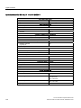
Table of contents
Preface ...................................................................................................................................................... 3
1
2
3
General specifications ............................................................................................................................. 21
1.1
Standards, certificates and approvals..........................................................................................21
1.2
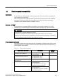
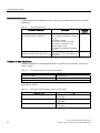
Electromagnetic compatibility ......................................................................................................29
1.3
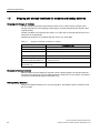
Shipping and storage conditions for modules and backup batteries ...........................................32
1.4
Mechanical and ambient conditions for S7-400 operation...........................................................34
1.5
Information on insulation tests, protection class and degree of protection..................................36
Rack ........................................................................................................................................................ 37
2.1
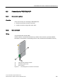
Function and design of the racks .................................................................................................37
2.2
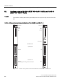
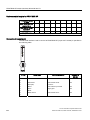
The racks UR1 (6ES7400-1TAx1-0AA0) and UR2 (6ES7400-1JAx1-0AA0) ..............................39
2.3
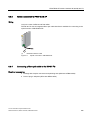
UR2-H Rack 6ES7400-2JAx0-0AA0) ..........................................................................................41
2.4
Rack CR2 (6ES7401-2TA01-0AA0) ............................................................................................43
2.5
Rack CR3 (6ES7401-1DA01-0AA0) ............................................................................................45
2.6
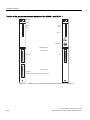
Racks ER1 (6ES7403-1TAx1-0AA0) and ER2 (6ES7403-1JAx1-0AA0) ....................................46
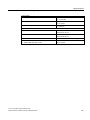
Power supply modules............................................................................................................................. 49
3.1
Common characteristics of the power supply modules ...............................................................49
3.2
Redundant power supply modules ..............................................................................................51
3.3
Backup battery (option)................................................................................................................53
3.4
Operator controls and indicators..................................................................................................55
3.5
Fault/Error messages via LEDs ...................................................................................................59
3.6
Power supply module PS 407 4A (6ES7407-0DA01-0AA0)........................................................65
3.7
Power supply module PS 407 4A (6ES7407-0DA02-0AA0)........................................................68
3.8
Power supply modules PS 407 10A (6ES7407-0KA01-0AA0) and PS 10A R (6ES74070KR00-0AA0) ...............................................................................................................................71
3.9
Power supply modules PS 407 10A (6ES7407-0KA02-0AA0) and PS 10A R (6ES74070KR02-0AA0) ...............................................................................................................................74
3.10
Power supply module PS 407 20A (6ES7407-0RA01-0AA0)......................................................77
3.11
Power supply module PS 407 20A (6ES7407-0RA02-0AA0)......................................................79
3.12
Power supply module PS 405 4A (6ES7405-0DA01-0AA0)........................................................81
3.13
Power supply module PS 405 4A (6ES7405-0DA02-0AA0)........................................................83
3.14
Power supply modules PS 405 10A (6ES7405-0KA01-0AA0) and PS 405 10A R (4050KR00-0AA0) ...............................................................................................................................85
3.15
Power supply modules PS 405 10A (6ES7405-0KA02-0AA0) and PS 405 10A R (4050KR02-0AA0) ...............................................................................................................................87
S7-400 Automation System Module Data
Reference Manual, Edition 09/2009, A5E00850736-06
7
Table of contents
4
8
3.16
Power supply module PS 405 20A (6ES7405-0RA01-0AA0)..................................................... 89
3.17
Power supply module PS 405 20A (6ES7405-0RA02-0AA0)..................................................... 91
Digital modules ........................................................................................................................................ 93
4.1
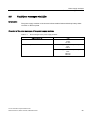
Module overview ......................................................................................................................... 93
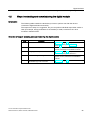
4.2
Steps in selecting and commissioning the digital module........................................................... 95
4.3
4.3.1
4.3.2
4.3.3
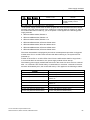
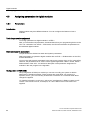
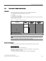
Assigning parameters to digital modules .................................................................................... 96
Parameters.................................................................................................................................. 96
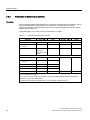
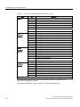
Parameters of digital input modules............................................................................................ 97
Parameters of digital output modules ......................................................................................... 98
4.4
4.4.1
4.4.2
4.4.3
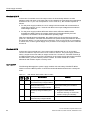
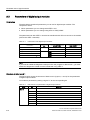
Diagnostics for digital modules ................................................................................................... 99
General information about diagnostic messages........................................................................ 99
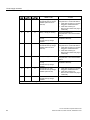
Diagnostic messages of the digital modules............................................................................. 100
Causes of errors and remedies for digital modules .................................................................. 101
4.5
Interrupts of the digital modules................................................................................................ 103
4.6
Input characteristic curve for digital inputs................................................................................ 105
4.7
Digital input module SM 421; DI 32 x DC 24 V (6ES7421-1BL01-0AA0)................................. 106
4.8
4.8.1
4.8.2
4.8.3
Digital input module SM 421; DI 16 x DC 24 V (6ES7421-7BH01-0AB0) ................................ 110
Features .................................................................................................................................... 110
Assigning parameters to the SM 421; DI 16 x DC 24 V............................................................ 115
Behavior of the SM 421; DI 16 x DC 24 V ................................................................................ 117
4.9
Digital input module SM 421; DI 16 x AC 120 V (6ES7421-5EH00-0AA0) .............................. 120
4.10
4.10.1
4.10.2
Digital input module SM 421; DI 16 x UC 24/60 V (6ES7421-7DH00-0AB0) ........................... 124
Features .................................................................................................................................... 124
Assigning parameters to the SM 421; DI 16 x UC 24/60 V....................................................... 128
4.11
Digital input module SM 421; DI 16 x UC 120/230 V (6ES7 421-1FH00-0AA0) ...................... 130
4.12
Digital input module SM 421; DI 16 x UC 120/230 V (6ES7421-1FH20-0AA0) ....................... 134
4.13
Digital input module SM 421; DI 32xUC 120 V (6ES7421-1EL00-0AA0)................................. 138
4.14
Digital output module SM 422; DO 16 x DC 24 V/2 A; (6ES7422-1BH11-0AA0)..................... 142
4.15
4.15.1
4.15.2
Digital output module SM 422; DO 16 x DC 20-125 V/1.5 A (6ES7422-5EH10-0AB0) ........... 146
Features .................................................................................................................................... 146
Assigning parameters to the SM 422; DO 16 x DC 20-125 V/1.5 A ......................................... 150
4.16
Digital output module SM 422; DO 32 x DC 24 V/0.5 A (6ES7422-1BL00-0AA0) ................... 151
4.17
4.17.1
4.17.2
4.17.3
Digital output module SM 422; DO 32 x DC 24 V/0.5 A (6ES7422-7BL00-0AB0) ................... 155
Features .................................................................................................................................... 155
Assigning parameters to the SM 422; DO 32 x DC 24 V/0.5 A ................................................ 159
Behavior of the SM 422; DO 32 x DC 24 V/0.5 A ..................................................................... 160
4.18
Digital output module SM 422; DO 8 x AC 120/230 V/5 A (6ES7422-1FF00-0AA0)................ 161
4.19
Digital output module SM 422; DO 16 x AC 120/230 V/2 A (6ES7422-1FF00-0AA0) ............. 165
4.20
4.20.1
4.20.2
Digital output module SM 422; DO 16 x AC 20-120 V/2 A (6ES7422-5EH00-0AB0)............... 169
Features .................................................................................................................................... 169
Assigning parameters to the SM 422; DO 16 x AC 20-120 V/2 A ............................................ 173
4.21
Relay output module SM 422; DO 16 x UC 30/230 V/Rel. 5 A (6ES7422-1HH00-0AA0)........ 174
S7-400 Automation System Module Data
Reference Manual, Edition 09/2009, A5E00850736-06
Table of contents
5
Analog modules ..................................................................................................................................... 179
5.1
General information ...................................................................................................................179
5.2
Module overview ........................................................................................................................180
5.3
Steps for commissioning analog modules .................................................................................183
5.4
5.4.1
5.4.2
5.4.3
5.4.4
5.4.5
5.4.6
5.4.7
5.4.8
5.4.9
Representation of analog values ...............................................................................................184
General information ...................................................................................................................184
Representation of analog values of analog input channels .......................................................185
Binary representation of input ranges........................................................................................186
Representation of analog values in voltage measuring ranges.................................................188
Representation of analog values in the current measuring ranges ...........................................190
Representation of analog values for resistance-type sensors...................................................192
Representation of analog values for resistance thermometer ...................................................193
Representation of analog values for thermocouples .................................................................196
Representation of analog values for analog output channels....................................................201
5.5
Setting the measuring method and ranges of analog input channels........................................205
5.6
5.6.1
5.6.2
5.6.3
5.6.4
Behavior of the analog modules ................................................................................................208
Introduction ................................................................................................................................208
Effect of supply voltage and operating mode.............................................................................209
Effect of the value range for analog values ...............................................................................210
Effect of operational limit and basic error limit ...........................................................................211
5.7
Conversion, cycle, settling and response time of analog modules............................................212
5.8
5.8.1
5.8.2
5.8.3
Assigning parameters to analog modules..................................................................................216
General information about parameter assignment ....................................................................216
Parameters of analog input modules .........................................................................................217
Parameters of analog output modules.......................................................................................219
5.9
Connecting sensors to analog inputs.........................................................................................220
5.10
Connecting voltage sensors.......................................................................................................223
5.11
Connecting current sensors .......................................................................................................224
5.12
Connecting resistance thermometers and resistors ..................................................................228
5.13
Connecting thermocouples ........................................................................................................231
5.14
Connecting loads/actuators to analog outputs...........................................................................237
5.15
Connecting loads/actuators to voltage outputs..........................................................................238
5.16
Connecting loads/actuators to current outputs ..........................................................................241
5.17
Diagnostics functions of analog modules ..................................................................................242
5.18
Interrupts of analog modules .....................................................................................................246
5.19
5.19.1
5.19.2
5.19.3
Analog input module SM 431; AI 8 x 13 Bit (6ES7431-1KF00-0AB0) .......................................248
Features .....................................................................................................................................248
Commissioning the SM 431; AI 8 x 13 Bit .................................................................................254
Measuring methods and measuring ranges of SM 431; AI 8 x 13 Bit .......................................255
5.20
5.20.1
5.20.2
5.20.3
Analog input module SM 431; AI 8 x 14 Bit (6ES7431-1KF10-0AB0) .......................................257
Features .....................................................................................................................................257
Commissioning the SM 431; AI 8 x 14 Bit .................................................................................267
Measuring methods and measuring ranges of SM 431; AI 8 x 14 Bit .......................................269
5.21
Analog input module SM 431; AI 8 x 14 Bit (6ES7431-1KF20-0AB0) .......................................274
S7-400 Automation System Module Data
Reference Manual, Edition 09/2009, A5E00850736-06
9
Table of contents
6
7
10
5.21.1
5.21.2
5.21.3
Features .................................................................................................................................... 274
Commissioning the SM 431; AI 8 x 14 Bit................................................................................. 279
Measuring methods and measuring ranges of SM 431; AI 8 x 14 Bit ...................................... 281
5.22
5.22.1
5.22.2
5.22.3
Analog input module SM 431; AI 16 x 13 Bit (6ES7431-0HH00-0AB0) ................................... 284
Features .................................................................................................................................... 284
Commissioning the SM 431; AI 16 x 13 Bit............................................................................... 290
Measuring methods and measuring ranges of SM 431; AI 16 x 13 Bit .................................... 291
5.23
5.23.1
5.23.2
5.23.3
Analog input module SM 431; AI 16 x 16 Bit (6ES7431-7QH00-0AB0) ................................... 293
Features .................................................................................................................................... 293
Commissioning the SM 431; AI 16 x 16 Bit............................................................................... 303
Measuring methods and measuring ranges of SM 431; AI 16 x 16 Bit .................................... 306
5.24
5.24.1
5.24.2
5.24.3
Analog input module SM 431; AI 8 x RTD x 16 Bit (6ES7431-7KF10-0AB0)........................... 311
Features .................................................................................................................................... 311
Commissioning the SM 431; AI 8 x RTD x 16 Bit ..................................................................... 317
Measuring methods and measuring ranges of the SM 431; AI 8 x RTD x 16 Bit ..................... 320
5.25
5.25.1
5.25.2
5.25.3
Analog input module SM 431; AI 8 x 16 Bit (6ES7431-7KF00-0AB0) ...................................... 321
Features .................................................................................................................................... 321
Commissioning the SM 431; AI 8 x 16 Bit................................................................................. 328
Measuring methods and measuring ranges of SM 431; AI 8 x 16 Bit ...................................... 333
5.26
5.26.1
5.26.2
5.26.3
Analog output module SM 432; AO 8 x 13 Bit (6ES7432-1HF00-0AB0).................................. 335
Features .................................................................................................................................... 335
Commissioning the SM 432; AO 8 x 13 Bit............................................................................... 340
Output ranges of the SM 432; AO 8 x 13 Bit............................................................................. 340
Interface modules .................................................................................................................................. 343
6.1
Common features of the interface modules .............................................................................. 343
6.2
Interface modules IM 460-0 (6ES7 460-0AA01-0AB0) and IM 461-0 (6ES7 461-0AA010AA0) ........................................................................................................................................ 348
6.3
Interface modules IM 460-1 (6ES7460-1BA01-0AB0) and IM 461-1 (6ES7461-1BA010AA0) ........................................................................................................................................ 351
6.4
Interface modules IM 460-3 (6ES7460-3AA01-0AB0) and IM 461-3 (6ES7461-3AA010AA0) ........................................................................................................................................ 355
6.5
Interface modules IM 460-4; (6ES7460-4AA01-0AB0) and IM 461-4; (6ES7461-4AA010AA0) ........................................................................................................................................ 358
S5 interface IM 463-2 ............................................................................................................................ 361
7.1
Using SIMATIC S5 expansion units in an S7-400 .................................................................... 361
7.2
Rules for connecting S5 expansion units.................................................................................. 363
7.3
Operator controls and indicators............................................................................................... 364
7.4
Installing and connecting the IM 463-2 ..................................................................................... 366
7.5
Setting the operating modes of the IM 314 ............................................................................... 367
7.6
Configuring S5 modules for operation in the S7-400................................................................ 370
7.7
Pin assignments of the 721 cable ............................................................................................. 372
7.8
Terminating connector for IM 314 ............................................................................................. 374
7.9
Specifications IM463-2 (6ES7463-2AA00-0AA0) ..................................................................... 375
S7-400 Automation System Module Data
Reference Manual, Edition 09/2009, A5E00850736-06
Table of contents
8
9
10
A
B
C
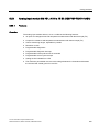
PROFIBUS DP master interface IM 467/IM 467 FO .............................................................................. 377
8.1
8.1.1
8.1.2
PROFIBUS DP master interface IM 467/IM 467 FO..................................................................377
Overview ....................................................................................................................................377
Indicators and the mode selector...............................................................................................380
8.2
Configuration..............................................................................................................................382
8.3
8.3.1
8.3.2
8.3.3
8.3.4
Connection to PROFIBUS DP ...................................................................................................383
Connection options ....................................................................................................................383
Bus connector ............................................................................................................................383
Optical connection to PROFIBUS DP........................................................................................385
Connecting a fiber-optic cable to the IM 467 FO .......................................................................385
8.4
8.4.1
8.4.2
Specifications .............................................................................................................................389
Specifications of the IM 467 (6ES7467-5GJ02-0AB0)) .............................................................389
Specifications of the IM 467 FO (6ES7467-5FJ00-0AB0) .........................................................390
Cable duct and fan subassemblies ........................................................................................................ 393
9.1
Features .....................................................................................................................................393
9.2
Fan monitoring in the fan subassemblies ..................................................................................394
9.3
Cable duct (6ES7408-0TA00-0AA0)..........................................................................................396
9.4
The 120/230 VAC fan subassembly (6ES7408-1TB00-0XA0) ..................................................397
9.5
The 24 V DC fan subassembly (6ES7408-1TA01-0XA0)..........................................................400
RS 485 repeater .................................................................................................................................... 403
10.1
Introduction ................................................................................................................................403
10.2
Applications and features (6ES7972-0AA01-0XA0) ..................................................................404
10.3
Design of the RS 485 repeater (6ES7972-0AA01-0XA0)..........................................................405
10.4
RS 485 repeater in ungrounded and grounded operation .........................................................406
10.5
Specifications .............................................................................................................................409
Parameter sets of signal modules.......................................................................................................... 411
A.1
How to assign the parameters for signal modules in the user program ....................................411
A.2
Parameters of digital input modules ..........................................................................................413
A.3
Parameters of digital output modules ........................................................................................416
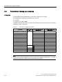
A.4
Parameters of analog input modules .........................................................................................418
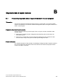
Diagnostic data of signal modules ......................................................................................................... 421
B.1
Evaluating diagnostic data of signal modules in the user program ...........................................421
B.2
Structure and contents of diagnostic data bytes 0 and 1...........................................................422
B.3
Diagnostic data of the digital input modules as of byte 2 ..........................................................423
B.4
Diagnostic data of the digital output modules as of byte 2 ........................................................428
B.5
Diagnostic data of the analog input modules as of byte 2 .........................................................435
Accessories and spare parts.................................................................................................................. 443
C.1
Accessories and spare parts......................................................................................................443
S7-400 Automation System Module Data
Reference Manual, Edition 09/2009, A5E00850736-06
11
Table of contents
D
E
Directive on handling electrostatic sensitive devices (ESD)................................................................... 447
D.1
ESD: What are the directives for handling electrostatic sensitive devices? ............................. 447
D.2
Electrostatic charging of persons.............................................................................................. 448
D.3
Basic protective measures against electrostatic discharge ...................................................... 449
List of abbreviations............................................................................................................................... 451
E.1
List of abbreviations .................................................................................................................. 451
Glossary ................................................................................................................................................ 455
Index...................................................................................................................................................... 469
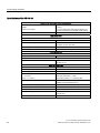
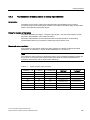
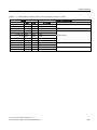
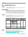
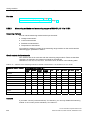
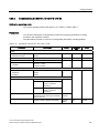
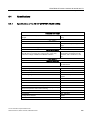
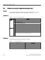
Tables
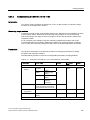
Table 1- 1
Use in industry ............................................................................................................................ 22
Table 1- 2
Products that fulfill the requirements of the low-voltage directive............................................... 22
Table 1- 3
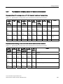
Pulse-shaped interference .......................................................................................................... 29
Table 1- 4
Sinusoidal interference................................................................................................................ 30
Table 1- 5
Interference emission of electromagnetic fields.......................................................................... 30
Table 1- 6
Interference emission via the mains AC power supply ............................................................... 30
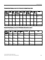
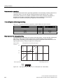
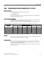
Table 1- 7
Shipping and storage conditions for modules ............................................................................. 32
Table 1- 8
Mechanical ambient conditions................................................................................................... 34
Table 1- 9
Test for mechanical ambient conditions...................................................................................... 35
Table 1- 10
Climatic ambient conditions ........................................................................................................ 35
Table 1- 11
Test voltages............................................................................................................................... 36
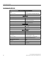
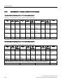
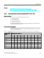
Table 3- 1
Redundant power supply modules.............................................................................................. 51
Table 3- 2
LEDs INTF, 5 VDC, 24 VDC ....................................................................................................... 56
Table 3- 3
LEDs BAF, BATTF ...................................................................................................................... 56
Table 3- 4
LEDs BAF, BATT1F, BATT2F..................................................................................................... 56
Table 3- 5
Function of the operator controls of the power supply modules ................................................. 57
Table 3- 6
Error messages of the power supply modules............................................................................ 59
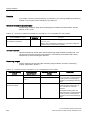
Table 3- 7
INTF, 5 VDC, 24 VDC LEDs ....................................................................................................... 60
Table 3- 8
BAF, BATTF; BATT.INDIC LEDs on BATT................................................................................. 62
Table 3- 9
BAF, BATT1F, BATT2F, BATT.INDIC LEDs on 1BATT ............................................................. 63
Table 3- 10
BAF, BATT1F, BATT2F, BATT.INDIC LEDs on 2BATT ............................................................. 63
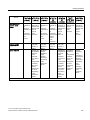
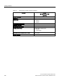
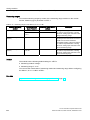
Table 4- 1
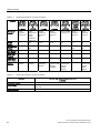
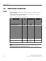
Digital input modules: overview of features ................................................................................ 93
Table 4- 2
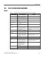
Digital output modules: overview of features .............................................................................. 94
Table 4- 3
Relay output module: overview of features................................................................................. 94
Table 4- 4
Parameters of digital input modules............................................................................................ 97
Table 4- 5
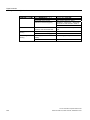
Parameters of digital output modules ......................................................................................... 98
12
S7-400 Automation System Module Data
Reference Manual, Edition 09/2009, A5E00850736-06
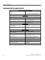
Table of contents
Table 4- 6
Diagnostic messages of the digital modules..............................................................................100
Table 4- 7
Diagnostic messages of the digital modules, causes of errors and remedies...........................101
Table 4- 8
Parameters of SM 421; DI 16 x DC 24 V...................................................................................115
Table 4- 9
Relationships of the analog input values on the CPU's operating state and on the L+
supply voltage ............................................................................................................................117
Table 4- 10
Relationships between the input values of errors and the configuration ...................................118
Table 4- 11
Parameters of the SM 421; DI 16 x UC 24/60 V........................................................................128
Table 4- 12
Parameters of the SM 421; DO 16 x DC 20-125 V/1.5 A ..........................................................150
Table 4- 13
Parameters of SM 422; DO 32 x DC 24 V/0.5 A........................................................................159
Table 4- 14
Relationships of the analog output values on the CPU's operating state and on the L+
supply voltage ............................................................................................................................160
Table 4- 15
Parameters of the SM 422; DO 16 x AC 20-120 V/2 A .............................................................173
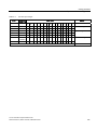
Table 5- 1
Analog input modules: overview of features ..............................................................................180
Table 5- 2
Analog output modules: overview of features............................................................................182
Table 5- 3
Steps from the selection of analog modules to commissioning.................................................183
Table 5- 4
Example: Bit pattern of a 16-bit and 13-bit analog value...........................................................184
Table 5- 5
Supported analog value resolutions ..........................................................................................185
Table 5- 6
Bipolar input ranges ...................................................................................................................186
Table 5- 7
Unipolar input ranges.................................................................................................................186
Table 5- 8
Life-zero input ranges ................................................................................................................187
Table 5- 9
Representation of analog values in the ±1 V to ±10 V voltage measuring ranges....................188
Table 5- 10
Representation of analog values in the ±25 to ±500 mV voltage measuring ranges ................188
Table 5- 11
Representation of analog values in the voltage measuring ranges 1 to 5 V and 0 to 10 V.......189
Table 5- 12
Representation of analog values in the ±3.2 mA to ±20 mA current measuring ranges ...........190
Table 5- 13
Representation of analog values in current measuring ranges 0 to 20 mA...............................190
Table 5- 14
Representation of analog values in current measuring ranges 4 to 20 mA...............................191
Table 5- 15
Analog value representation for resistance-type sensors from 48 Ω to 6 kΩ ............................192
Table 5- 16
Representation of analog values for Pt 100/200/500/1000 resistance thermometers...............193
Table 5- 17
Representation of analog values for Pt 100/200/500/1000 resistance thermometers...............193
Table 5- 18
Analog value representation for resistance thermometers Ni100, 120, 200, 500, 1000 ...........194
Table 5- 19
Analog value representation for resistance thermometers Ni 100, 120, 200, 500, 1000 ..........194
Table 5- 20
Representation of analog values for Cu 10 standard resistance thermometers .......................195
Table 5- 21
Representation of analog values for Cu 10 climatic resistance thermometers .........................195
Table 5- 22
Representation of analog values for thermocouples type B ......................................................196
Table 5- 23
Representation of analog values for thermocouples type E ......................................................196
Table 5- 24
Representation of analog values for thermocouples type J.......................................................197
Table 5- 25
Representation of analog values for thermocouples type K ......................................................197
S7-400 Automation System Module Data
Reference Manual, Edition 09/2009, A5E00850736-06
13
Table of contents
Table 5- 26
Representation of analog values for thermocouples type L...................................................... 198
Table 5- 27
Representation of analog values for thermocouples type N ..................................................... 198
Table 5- 28
Representation of analog values for thermocouple types R, S................................................. 199
Table 5- 29
Representation of analog values for thermocouples type T ..................................................... 199
Table 5- 30
Representation of analog values for thermocouples type U ..................................................... 200
Table 5- 31
Bipolar output ranges ................................................................................................................ 201
Table 5- 32
Unipolar output ranges.............................................................................................................. 202
Table 5- 33
Life-zero input ranges ............................................................................................................... 202
Table 5- 34
Representation of analog values in the ±10 V output range..................................................... 203
Table 5- 35
Representation of analog values in the 0 V to 10 V and 1 V to 5 V output ranges................... 203
Table 5- 36
Representation of analog values in the ±20 mA output range.................................................. 204
Table 5- 37
Representation of analog values in the 0 to 20 mA and 4 to 20 mA output ranges ................. 204
Table 5- 38
Dependencies of the analog IO values on the CPU's operating State and on the L+
supply voltage ........................................................................................................................... 209
Table 5- 39
Reaction of analog input modules as a function of the actual analog value within the value
range ......................................................................................................................................... 210
Table 5- 40
Behavior of the analog output modules as a function of the position of the analog value
within the value range ............................................................................................................... 210
Table 5- 41
Parameters of analog input modules ........................................................................................ 217
Table 5- 42
Parameters of analog output modules ...................................................................................... 219
Table 5- 43
Diagnostic messages of the analog input modules .................................................................. 243
Table 5- 44
Diagnostic messages of the analog input modules, causes of errors and remedies................ 244
Table 5- 45
Parameters of the SM 431; AI 8 x 13 Bit................................................................................... 254
Table 5- 46
Channels for resistance measurement of the SM 431; AI 8 x 13 Bit ........................................ 255
Table 5- 47
Measuring ranges of the SM 431; AI 8 x 13 Bit ........................................................................ 256
Table 5- 48
Parameters of the SM 431; AI 8 x 14 Bit................................................................................... 267
Table 5- 49
Selection of the measuring method for channel n and channel n+1 of the SM 431;
AI 8 x 14 Bit (6ES7431-1KF10-0AB0)....................................................................................... 270
Table 5- 50
Channels for resistance and temperature measurement of the SM 431; AI 8 x 14 Bit............. 271
Table 5- 51
Thermocouple with reference junction compensation via RTD on channel 0........................... 271
Table 5- 52
Measuring ranges of the SM 431; AI 8 x 14 Bit (6ES7431-1KF10-0AB0) ................................ 272
Table 5- 53
Parameters of the SM 431; AI 8 x 14 Bit (6ES7431-1KF20-0AB0) .......................................... 279
Table 5- 54
Interference frequency suppression and filter settling time with smoothing ............................. 280
Table 5- 55
Selection of the measuring method for channel n and channel n+1 of the SM 431;
AI 8 x 14 Bit (6ES7431-1KF10-0AB0)....................................................................................... 281
Table 5- 56
Channels for resistance measurement of the SM 431; AI 8 x 14 Bit (6ES7431-1KF100AB0) ........................................................................................................................................ 282
Table 5- 57
Measuring ranges of the SM 431; AI 8 x 14 Bit (6ES7431-1KF10-0AB0) ................................ 282
14
S7-400 Automation System Module Data
Reference Manual, Edition 09/2009, A5E00850736-06
Table of contents
Table 5- 58
Parameters of the SM 431; AI 16 x 13 Bit .................................................................................290
Table 5- 59
Selection of the measuring method for channel n and channel n+1 of the SM 431;
AI 16 x 13 Bit..............................................................................................................................291
Table 5- 60
Measuring ranges of the SM 431; AI 16 x 13 Bit .......................................................................292
Table 5- 61
Parameters of the SM 431; AI 16 x 16 Bit .................................................................................303
Table 5- 62
Diagnostic information of the SM 431; AI 16 x 16 Bit ................................................................305
Table 5- 63
Selection of the measuring method for channel n and channel n+1 of the SM 431;
AI 16 x 16 Bit..............................................................................................................................306
Table 5- 64
Channels for resistance and temperature measurement of the SM 431; AI 16 x 16 Bit ...........307
Table 5- 65
Reference junction compensation via RTD on channel 0 of the SM 431; AI 16 x 16 Bit...........307
Table 5- 66
Measuring ranges of the SM 431; AI 16 x 16 Bit .......................................................................308
Table 5- 67
Points to note when checking for "Underflow" ...........................................................................310
Table 5- 68
Parameters of the SM 431; AI 8 x RTD x 16 Bit ........................................................................317
Table 5- 69
Diagnostic information of the SM 431; AI 8 x RTD x 16 Bit .......................................................319
Table 5- 70
Measuring ranges of the SM 431; AI 8 x RTD x 16 Bit ..............................................................320
Table 5- 71
Parameters of the SM 431; AI 8 x 16 Bit ...................................................................................328
Table 5- 72
How response times depend on the configured interference frequency suppression and
smoothing of the SM 431; AI 8 x 16 Bit .....................................................................................329
Table 5- 73
Diagnostic information of the SM 431; AI 8 x 16 Bit ..................................................................332
Table 5- 74
Measuring ranges of the SM 431; AI 8 x 16 Bit .........................................................................333
Table 5- 75
Output ranges of the SM 432; AO 8 x 13 Bit .............................................................................340
Table 6- 1
Interface modules of the S7-400................................................................................................343
Table 6- 2
Overview of the connections......................................................................................................343
Table 6- 3
Cable for different connections ..................................................................................................345
Table 6- 4
Terminators for the Receive IMs................................................................................................345
Table 6- 5
Cables for interface modules .....................................................................................................347
Table 6- 6
Operator controls and indicators on the send IM.......................................................................349
Table 6- 7
Operator controls and indicators of the receive IM ....................................................................349
Table 6- 8
Operator controls and indicators on the send IM.......................................................................353
Table 6- 9
Operator controls and indicators of the receive IM ....................................................................353
Table 6- 10
Operator controls and indicators on the send IM.......................................................................356
Table 6- 11
Operator controls and indicators of the receive IM ....................................................................356
Table 6- 12
Operator controls and indicators on the send IM.......................................................................359
Table 6- 13
Operator controls and indicators of the receive IM ....................................................................359
Table 7- 1
S5 interface modules .................................................................................................................362
Table 7- 2
LEDs of the IM 463-2 .................................................................................................................365
Table 7- 3
Switch position: Interface selector of the IM 463-2 ....................................................................365
S7-400 Automation System Module Data
Reference Manual, Edition 09/2009, A5E00850736-06
15
Table of contents
Table 7- 4
Switch position: Cable length selector of the IM 463-2............................................................. 365
Table 7- 5
Settings of the IM 314 using expansion units ........................................................................... 368
Table 7- 6
Settings address areas on the IM 314 ...................................................................................... 369
Table 7- 7
Pin assignments of the 721 cable ............................................................................................. 372
Table 7- 8
Assignment of the terminator 760-1AA11 ................................................................................. 374
Table 8- 1
Operating modes of the IM 467/467 FO ................................................................................... 380
Table 9- 1
Function of fan monitoring......................................................................................................... 394
Table 10- 1
Maximum cable length of a segment ........................................................................................ 404
Table 10- 2
Maximum cable length between two RS 485 repeaters ........................................................... 404
Table A- 1
SFCs for assigning parameters to signal modules ................................................................... 411
Table A- 2
Parameters of digital input modules.......................................................................................... 413
Table A- 3
Data record 1 for parameters of digital input modules.............................................................. 414
Table A- 4
Data record 1 for parameters of digital input modules.............................................................. 415
Table A- 5
Parameters of the digital output modules ................................................................................. 416
Table A- 6
Data record 1 for parameters of digital output modules............................................................ 416
Table A- 7
Data record 1 for parameters of digital output modules............................................................ 417
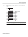
Table A- 8
Parameters of analog input modules ........................................................................................ 418
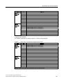
Table B- 1
Bytes 0 and 1 of diagnostic data............................................................................................... 422
Table B- 2
Codes of the module types ....................................................................................................... 422
Table B- 3
Bytes 2 and 3 of the diagnostic data of the SM 421; DI 16 x DC 24 V ..................................... 423
Table B- 4
Bytes 4 to 8 of the diagnostic data of the SM 421; DI 16 x DC 24 V ........................................ 424
Table B- 5
Diagnostic byte for a channel of the SM 421; DI 16 x DC 24 V ................................................ 425
Table B- 6
Bytes 2 and 3 of the diagnostic data of the SM 421; DI 16 x UC 24/60 V ................................ 425
Table B- 7
Bytes 4 to 8 of the diagnostic data of the SM 421; DI 16 x UC 24/60 V ................................... 426
Table B- 8
Diagnostic byte for a channel of the SM 421; DI 16 x DC 24 V ................................................ 427
Table B- 9
Bytes 2 and 3 of the diagnostic data of the SM 422; DO 16 x DC 20-125 V/1.5 A................... 428
Table B- 10
Bytes 4 to 8 of the diagnostic data of the SM 422; DO 16 x DC 20-125 V/1.5 A...................... 429
Table B- 11
Diagnostic byte for a channel of the SM 422; DO 16 x DC 20-125 V/1.5 A ............................. 430
Table B- 12
Bytes 2 and 3 of the diagnostic data of the SM 422; DO 32 x DC 24 V/0.5 A.......................... 430
Table B- 13
Bytes 4 to 10 of the diagnostic data of the SM 422; DO 32 x DC 24 V/0.5 A........................... 431
Table B- 14
Diagnostic byte for a channel of the SM 422; DO 32 x DC 24 V/0.5 A..................................... 432
Table B- 15
Bytes 2 and 3 of the diagnostic data of the SM 422; DO 16 x AC 20-120 V/2 A...................... 433
Table B- 16
Bytes 4 to 8 of the diagnostic data of the SM 422; DO 16 x AC 20-120 V/2 A......................... 433
Table B- 17
Diagnostic byte for a channel of the SM 422; DO 16 x AC 20-120 V/2 A................................. 434
Table B- 18
Bytes 2 and 3 of the diagnostic data of the SM 431; AI 16 x 16 bit .......................................... 435
Table B- 19
Bytes 4 to 8 of the diagnostic data of the SM 431; AI 16 x 16 bit ............................................. 436
16
S7-400 Automation System Module Data
Reference Manual, Edition 09/2009, A5E00850736-06
Table of contents
Table B- 20
Diagnostic byte for a channel of the SM 431; AI 16 x 16 bit......................................................437
Table B- 21
Bytes 2 and 3 of the diagnostic data of the SM 431; AI 8 x RTD x 16 bit..................................437
Table B- 22
Bytes 4 to 7 of the diagnostic data of the SM 431; AI 8 x RTD x 16 bit.....................................438
Table B- 23
Even diagnostic byte for a channel of the SM 431; AI 8 x RTD x 16 bit ....................................439
Table B- 24
Odd diagnostic byte for a channel of the SM 431; AI 8 x RTD x 16 bit .....................................439
Table B- 25
Bytes 2 and 3 of the diagnostic data of the SM 431; AI 8 x 16 bit .............................................439
Table B- 26
Bytes 4 to 7 of the diagnostic data of the SM 431; AI 8 x 16 bit ................................................440
Table B- 27
Even diagnostic byte for a channel of the SM 431; AI 8 x 16 bit ...............................................441
Table B- 28
Odd diagnostic byte for a channel of the SM 431; AI 8 x 16 bit.................................................441
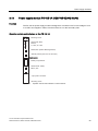
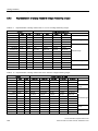
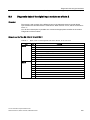
Figures
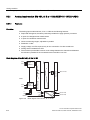
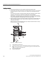
Figure 1-1
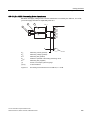
Power supply to the backup battery.............................................................................................26
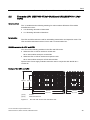
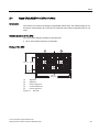
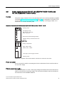
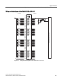
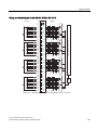
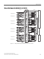
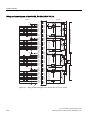
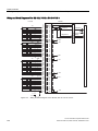
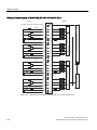
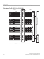
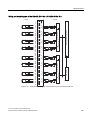
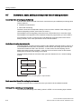
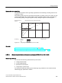
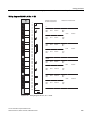
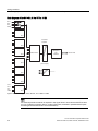
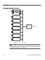
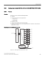
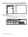
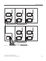
Figure 2-1
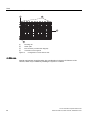
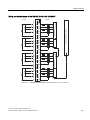
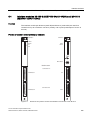
Configuration of a rack with 18 slots ............................................................................................38
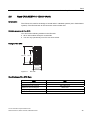
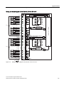
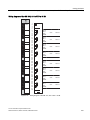
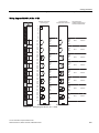
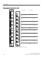
Figure 2-2
UR1 rack with 18 slots and UR2 with 9 slots ...............................................................................39
Figure 2-3
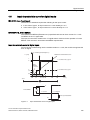
Rack dimensions..........................................................................................................................42
Figure 2-4
CR2 rack ......................................................................................................................................43
Figure 2-5
CR3 rack ......................................................................................................................................45
Figure 2-6
ER1 rack with 18 slots and ER2 with 9 slots ...............................................................................47
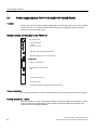
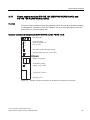
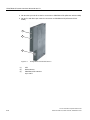
Figure 3-1
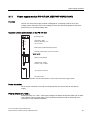
Operator controls and indicators on the PS 407 20A power supply module ...............................55
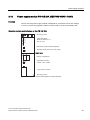
Figure 3-2
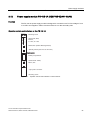
Operator controls and indicators on the PS 407 4A ....................................................................65
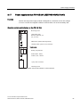
Figure 3-3
Operator controls and indicators on the PS 407 4A ....................................................................68
Figure 3-4
Operator controls and indicators of the PS 407 10A and PS 407 10A R ....................................71
Figure 3-5
Operator controls and indicators of the PS 407 10A and PS 407 10A R ....................................74
Figure 3-6
Operator controls and indicators on the PS 407 20 A .................................................................77
Figure 3-7
Operator controls and indicators on the PS 407 20A power supply module ...............................79
Figure 3-8
Operator controls and indicators on the PS 405 4A ....................................................................81
Figure 3-9
Operator controls and indicators on the PS 405 4A ....................................................................83
Figure 3-10
Operator Controls and Indicators on the PS 405 10A and the PS 405 10A R ............................85
Figure 3-11
Operator Controls and Indicators on the PS 405 10A and the PS 405 10A R ............................87
Figure 3-12
Operator controls and indicators on the PS 405 20A ..................................................................89
Figure 3-13
Operator controls and indicators on the PS 405 20A ..................................................................91
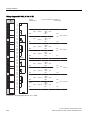
Figure 4-1
Input characteristic curve for digital inputs.................................................................................105
Figure 4-2
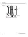
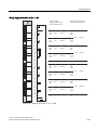
Wiring and block diagram of the SM 421; DI 32 x DC 24 V.......................................................107
Figure 4-3
Wiring and block diagram of the SM 421; DI 16 x DC 24 V.......................................................111
Figure 4-4
Wiring diagram for the redundant supply of sensors of the SM 421; DI 16 x DC 24 V .............112
S7-400 Automation System Module Data
Reference Manual, Edition 09/2009, A5E00850736-06
17
Table of contents
Figure 4-5
Wiring diagram of the SM 421; DI 16 x AC 120 ........................................................................ 121
Figure 4-6
Wiring and Block Diagram of the SM 421; DI 16 x UC 24/60 V................................................ 125
Figure 4-7
Circuit as for active high or active low input.............................................................................. 129
Figure 4-8
Wiring and block diagram of the SM 421; DI 16 x UC 120/230 V............................................. 131
Figure 4-9
Wiring and block diagram of the SM 421; DI 16 x UC 120/230 V............................................. 135
Figure 4-10
Wiring and block diagram of the SM 421; DI 32 x UC 120 V.................................................... 139
Figure 4-11
Wiring and Block Diagram of the SM 422; DO 16 x DC 24 V/2 A............................................. 143
Figure 4-12
Wiring diagram of the SM 422; DO 16 x DC 20-125 V/1.5 A.................................................... 147
Figure 4-13
Wiring and Block Diagram of the SM 422; DO 32 x DC 24 V/0.5 A.......................................... 152
Figure 4-14
Wiring and Block Diagram of the SM 422; DO 32 x DC 24 V/0.5 A.......................................... 156
Figure 4-15
Wiring and block diagram of the SM 422; DO 8 x AC 120/230 V/5 A....................................... 162
Figure 4-16
Wiring and block diagram of the SM 422; DO 16 x AC 120/230 V/2 A..................................... 166
Figure 4-17
Wiring diagram of the SM 422; DO 16 x AC 20-120 V/2 A ....................................................... 170
Figure 4-18
Wiring and block diagram of the SM 422; DO 16 x UC 30/230 V/Rel. 5 A ............................... 175
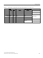
Figure 5-1
Example of the relative error of an analog output module ........................................................ 211
Figure 5-2
Scan time of an analog input or output module ........................................................................ 212
Figure 5-3
Example of the effect of smoothing on step responses ............................................................ 213
Figure 5-4
Settling and response times of the analog output channels ..................................................... 214
Figure 5-5
Connecting isolated sensors to an electrically isolated AI ........................................................ 221
Figure 5-6
Connecting non-isolated sensors to an isolated AI................................................................... 222
Figure 5-7
Connecting voltage sensors to an AI ........................................................................................ 223
Figure 5-8
Connecting 2-wire transducers to an isolated AI ...................................................................... 224
Figure 5-9
Connecting 2-wire transducers to an SM 431; 8 x 13 Bit.......................................................... 225
Figure 5-10
Connecting 4-wire transducers to an AI.................................................................................... 226
Figure 5-11
Connecting 4-wire transducers to an SM 431; 8 x 13 Bit.......................................................... 227
Figure 5-12
4-conductor connection of a resistance thermometer to an AI ................................................. 228
Figure 5-13
3-conductor connection of a resistance thermometer to an electrically isolated analog
input........................................................................................................................................... 229
Figure 5-14
2-conductor connection of a resistance thermometer to an electrically isolated analog
input........................................................................................................................................... 230
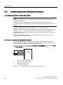
Figure 5-15
Thermocouple design................................................................................................................ 231
Figure 5-16
Connection of thermocouples without compensation or using the reference temperature
value to an isolated AI............................................................................................................... 233
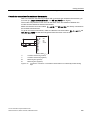
Figure 5-17
Connection of a thermocouple with reference junction (Order No. M72166-xxx00) to an
Isolated AI ................................................................................................................................. 235
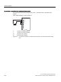
Figure 5-18
Connection of thermocouples of the same type with external compensation by means of a
resistance thermometer, connected to channel 0..................................................................... 236
18
S7-400 Automation System Module Data
Reference Manual, Edition 09/2009, A5E00850736-06
Table of contents
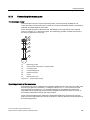
Figure 5-19
4-conductor connection of loads to a voltage output of an electrically isolated analog
output module ............................................................................................................................239
Figure 5-20
2-conductor connection of loads to a voltage output of an electrically isolated analog
output module ............................................................................................................................240
Figure 5-21
Connecting loads to a current output of an isolated AO ............................................................241
Figure 5-22
Start Information of OB 40: Which event has violated limits and triggered a hardware
interrupt ......................................................................................................................................247
Figure 5-23
Block diagram of the SM 431; AI 8 x 13 Bit ...............................................................................248
Figure 5-24
Wiring diagram SM 431; AI 8 x 13 Bit........................................................................................250
Figure 5-25
Block diagram of the SM 431; AI 8 x 14 Bit ...............................................................................258
Figure 5-26
Wiring diagram SM 431; AI 8 x 14 Bit........................................................................................259
Figure 5-27
Step response of the SM 431; AI 8 x 14 Bit...............................................................................269
Figure 5-28
Block diagram of the SM 431; AI 8 x 14 Bit ...............................................................................274
Figure 5-29
Wiring diagram SM 431; AI 8 x 14 Bit........................................................................................275
Figure 5-30
Step response of the SM 431; AI 8 x 14 Bit (6ES7 431-1KF20-0AB0)......................................280
Figure 5-31
Block diagram of the SM 431; AI 16 x 13 Bit .............................................................................285
Figure 5-32
Wiring diagram SM 431; AI 16 x 13 Bit......................................................................................286
Figure 5-33
Block diagram of the SM 431; AI 16 x 16 Bit .............................................................................294
Figure 5-34
Wiring diagram SM 431; AI 16 x 16 Bit......................................................................................295
Figure 5-35
Step response of the SM 431; AI 16 x 16 Bit (6ES7431-7QH00-0AB0)....................................305
Figure 5-36
Block diagram of the SM 431; AI 8 x RTD x 16 Bit ....................................................................312
Figure 5-37
Wiring diagram of the SM 431; AI 8 x RTD x 16 Bit...................................................................313
Figure 5-38
Step response of the SM 431; AI 8 x RTD x 16 Bit....................................................................318
Figure 5-39
Block diagram of the SM 431; AI 8 x 16 Bit ...............................................................................322
Figure 5-40
Wiring diagram SM 431; AI 8 x 16 Bit........................................................................................323
Figure 5-41
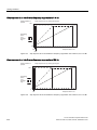
Step response at 10 Hz interference frequency suppression of the SM 431; AI 8 x 16 Bit.......330
Figure 5-42
Step response at 50 Hz interference frequency suppression of the SM 431; AI 8 x 16 Bit.......330
Figure 5-43
Step response at 60 Hz interference frequency suppression of the SM 431; AI 8 x 16 Bit.......331
Figure 5-44
Step response at 400 Hz interference frequency suppression of the SM 431; AI 8 x 16 Bit.....331
Figure 5-45
Block diagram of the SM 432; AO 8 x 13 Bit .............................................................................335
Figure 5-46
Wiring diagram of the SM 432; AO 8 x 13 Bit ............................................................................336
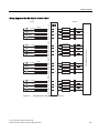
Figure 6-1
Example: Configuration with send IMs, receive IMs and terminators........................................346
Figure 6-2
Position of the operator controls and indicators of the IM 460-0 and IM 461-0.........................348
Figure 6-3
Position of the operator controls and indicators of the IM 460-1 and IM 461-1.........................352
Figure 6-4
Position of the operator controls and indicators of the IM 460-3 and IM 461-3.........................355
Figure 6-5
Position of the operator controls and indicators of the IM 460-4 and IM 461-4.........................358
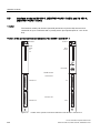
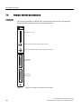
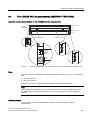
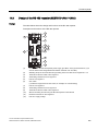
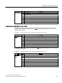
Figure 7-1
Layout of the controls and indicators of the IM 463-2................................................................364
S7-400 Automation System Module Data
Reference Manual, Edition 09/2009, A5E00850736-06
19
Table of contents
Figure 7-2
Connection variant for CCs and EUs via the IM 463-2 and IM 314.......................................... 371
Figure 8-1
Configuration of the IM 467/467 FO.......................................................................................... 378
Figure 8-2
LEDs of the IM 467/467 FO ...................................................................................................... 380
Figure 8-3
Connecting the bus connector to the IM 467 ............................................................................ 383
Figure 8-4
Optical connection to PROFIBUS DP ....................................................................................... 385
Figure 8-5
Installing the connector ............................................................................................................. 386
Figure 8-6
Inserting the fiber-optic cables into the IM 467 FO ................................................................... 387
Figure 9-1
Example of a message concept................................................................................................ 395
Figure 9-2
Front view of the cable duct ...................................................................................................... 396
Figure 9-3
Controls and indicators of the fan subassembly 120/230 VAC (6ES7408-1TB00-0XA0) ........ 397
Figure 9-4
Controls and indicators of the fan subassembly 24 VDC (6ES7408-1TA00-0XA0) ................. 400
Figure 10-1
RC network with 10 M Ohm for configuration with ungrounded reference potential ................ 407
Figure 10-2
Electrical isolation between the bus segments ......................................................................... 408
Figure 10-3
Block diagram of the RS 485 repeater...................................................................................... 410
Figure A-1
For example, byte 1 with the bits 0 - 7 ...................................................................................... 413
Figure A-2
Data record 1 for the parameters of analog input modules ...................................................... 419
Figure D-1
Electrostatic voltages which can build up on a person ............................................................. 448
20
S7-400 Automation System Module Data
Reference Manual, Edition 09/2009, A5E00850736-06
General specifications
1.1
1
Standards, certificates and approvals
Information on the type plate
Note
You will find the current approvals on the type plate of the respective product.
WARNING
Open Equipment
Death, serious injury or substantial material damage can occur.
S7 400 modules are classified as open equipment, This means that the S7 400 should only
be installed in an enclosure or cabinet.
Access to the enclosures or cabinets should only be possible with a key or with a tool, and
access should only be permitted for trained or approved personnel.
IEC 61131-2
The S7-400 automation system meets the requirements and criteria of standard IEC 61131-2
(Programmable Controllers, Part 2: Equipment Requirements and Tests.)
CE marking
Our products satisfy the requirements and protection objectives of the EC Directives listed
below and comply with the harmonized European standards (EN) promulgated in the Official
Journals of the European Community for programmable controllers:
● 2006/95/EC "Electrical Equipment Designed for Use within Certain Voltage Limits" (LowVoltage Directive)
● 2004/108/EC "Electromagnetic Compatibility" (EMC Directive)
● 94/9/EU "Devices and protection systems for use as prescribed in potentially explosive
areas" (Guidelines for Explosion Protection)
S7-400 Automation System Module Data
Reference Manual, Edition 09/2009, A5E00850736-06
21
General specifications
1.1 Standards, certificates and approvals
The EC Declarations of Conformity are available to the relevant authorities at the following
address:
Siemens Aktiengesellschaft
Industry Sector
I IA AS RD ST
P.O. Box 1963
D-92209 Amberg
These files are also available for download on the Customer Support Internet pages, under
"Declaration of Conformity".
EMC directive
SIMATIC products are designed for industrial applications.
Table 1- 1
Use in industry
Area of
application
Industry
Noise emission requirements
EN 61000-6-4: 2001
Noise immunity requirements
EN 61000-6-2: 2005
Low voltage directive
The products listed in the table below fulfill the requirements of EU directive 2006/95/EC,
"Low-voltage Directive". Adherence to this EU directive was tested in accordance with
DIN EN 61131-2 (corresponds to IEC 61131-2).
Table 1- 2
Products that fulfill the requirements of the low-voltage directive
Name
22
Order number
Digital input module SM 421;DI 32 x UC 120 V
6ES7 421-1EL00-0AA0
Digital input module SM 421;DI 16 x UC 120/230 V
6ES7 421-1FH00-0AA0
Digital output module SM 422;DO 8 x AC 120/230 V/5A
6ES7 422-1FF00-0AA0
Digital output module SM 422;DO 16 x AC 120/230 V/2A
6ES7 422-1FH00-0AB0
Relay output module SM 422;DO 16 x UC30/230 V/Rel5A
6ES7 422-1HH00-0AA0
Digital input module SM 421;DI 16 x UC 120/230 V
6ES7421-1FH20-0AA0
The 120/230 VAC fan subassembly
6ES7 408-1TB00-0XA0
PS 407 4A
6ES7 407-0DA01-0AA0
6ES7 407-0DA02-0AA0
PS 407 10A
6ES7 407-0KA01-0AA0
6ES7 407-0KA02-0AA0
PS 407 20 A
6ES7 407-0RA01-0AA0
6ES7 407-0RA02-0AA0
PS 407 10A R
6ES7 407-0KR00-0AA0
6ES7 407-0KR02-0AA0
S7-400 Automation System Module Data
Reference Manual, Edition 09/2009, A5E00850736-06
General specifications
1.1 Standards, certificates and approvals
Note
In the new releases, some of the devices listed above fulfill the requirements of the explosion
protection guidelines instead of those of the low-voltage directive. Please note the
information on the type plate.
Explosion protection guidelines
In accordance with EN 60079-15 (Electrical Apparatus for Potentially Explosive
Atmospheres; Type of Protection "n") and EN 60079-0 (Electrical apparatus for explosive
gas atmospheres - Part 0: General requirements)
II 3 G Ex nA II Parts 4 to 6
Marking for Australia and New Zealand
Our products comply with the requirements of the AS/NZS CISPR 11 standard (Class A).
Note
You will recognize the UL/CSA or cULus approvals given to your product from the markings
on the type plate.
UL approval
UL approval label
Underwriters Laboratories (UL) to the UL 508 Standard:
● Report E 248953
S7-400 Automation System Module Data
Reference Manual, Edition 09/2009, A5E00850736-06
23
General specifications
1.1 Standards, certificates and approvals
CSA certification
CSA certification
Canadian Standard Association (CSA) to Standard C 22.2 No. 142:
● Certification Record 212191-0-000
or
cULus approval
Underwriters Laboratories Inc., to
● UL 508 (Industrial Control Equipment)
● CSA C22.2 No. 142 (Process Control Equipment)
or cULus approval, Hazardous Location
+$=/2&
CULUS Listed 7RA9 INT. CONT. EQ. FOR HAZ. LOC.
Underwriters Laboratories Inc., complying with
● UL 508 (Industrial Control Equipment)
● CSA C22.2 No. 142 (Process Control Equipment)
● UL 1604 (Hazardous Location)
● CSA-213 (Hazardous Location)
APPROVED for Use in
● Cl. 1, Div. 2, GP. A, B, C, D T4A
● Cl. 1, Zone 2, GP. IIC T4
Observe the following note.
24
S7-400 Automation System Module Data
Reference Manual, Edition 09/2009, A5E00850736-06
General specifications
1.1 Standards, certificates and approvals
or cULus Approvals, Hazardous Location for Relay Modules
+$=/2&
CULUS Listed 7RA9 INT. CONT. EQ. FOR HAZ. LOC.
Underwriters Laboratories Inc., complying with
● UL 508 (Industrial Control Equipment)
● CSA C22.2 No. 142 (Process Control Equipment)
● UL 1604 (Hazardous Location)
● CSA-213 (Hazardous Location)
APPROVED for Use in
● Cl. 1, Div. 2, GP. A, B, C, D T4A
● Cl. 1, Zone 2, GP. IIC T4
● Cl. 1, Zone 2, AEx nC IIC T4
Read the following information
Note
This product must be installed according to the NEC (National Electric Code) stipulations.
When used in environments according to class I, division 2 (see above), S7-400 must be
mounted in an enclosure that corresponds to at least IP54 according to EN 60529.
You can find information about the use of S7-400 in hazardous areas of zone 2 in a separate
document, which is included in this documentation package.
S7-400 Automation System Module Data
Reference Manual, Edition 09/2009, A5E00850736-06
25
General specifications
1.1 Standards, certificates and approvals
CuULu requirements for hazardous location on the battery power supply for CPUs
The power supply to the backup battery of a CPU must be via a fire-resistant plug. The figure
below portrays the concept of such connection.
1
2
(1)
Battery or voltage supply
(2)
CPU with "Ext. Batt." connector
Figure 1-1
Power supply to the backup battery
The following conditions apply to the performance characteristics of this connection:
Voc (no load voltage) = 15V
Vmax = 15V
Isc (short-circuit current) = 50 mA
Imax = 50 mA
Ca = Battery/voltage supply capacity
Ci = 25 nF maximum
La = Battery/voltage supply inductance
Li = 2 mH maximum
The battery/voltage supply which provides the fire-resistant connection must have the
following values:
Battery/Power supply
CPU input "Ext. Batt." with cable
Voc
≤
Vmax (15V)
Isc
≤
Imax (50 mA)
Ca
≥
Ci + Cc (25nF + Cc)
La
≥
Li + Lc (2mH + Lc)
Cc = Cable capacity
Lc = Cable inductance
The batteries used must have the following properties:
● Battery technology: Li/SOCL2
● Model: AA
● Voltage: 3.6 V
The batteries stipulated by Siemens fulfill requirements that go beyond the ones mentioned
above.
You may only use batteries approved by Siemens!
Note
If you do not know the capacity and inductance of the cable, you can use the following
values:
Cc = 197 pF/m (60 pF/ft.), Lc = 0.66 pF/m (0.2 mH/ft)
26
S7-400 Automation System Module Data
Reference Manual, Edition 09/2009, A5E00850736-06
General specifications
1.1 Standards, certificates and approvals
Example
The Varta 4022 battery together with a 1.5 m long cable and a Leonhardy 02-02.1500 plug
meet these conditions.
FM Approval
Factory Mutual Approval Standard Class Number 3611, Class I, Division 2,
Group A, B, C, D.
Temperature class: T4 at 60° C ambient temperature
WARNING
Personal injury or property damage can result.
In hazardous areas, personal injury or property damage can result if you create or break an
electrical circuit during operation of an S7-400 (for example, by means of plug-in
connections, fuses, switches).
Do not create or break live electrical circuits unless you are certain there is no danger of
explosion.
If you use S7-400 under FM conditions, it has to be mounted in a housing, which at least
corresponds to IP54 in accordance with EN 60529.
Marine Approvals
Classification societies:
● ABS (American Bureau of Shipping)
● BV (Bureau Veritas)
● DNV (Det Norske Veritas)
● GL (Germanischer Lloyd)
● LRS (Lloyds Register of Shipping)
● Class NK (Nippon Kaiji Kyokai)
S7-400 Automation System Module Data
Reference Manual, Edition 09/2009, A5E00850736-06
27
General specifications
1.1 Standards, certificates and approvals
Safety requirements for installation
The S7-400 programmable controllers are "open type" equipment to the IEC 61131-2
standard and therefore adhere to the EU directive 2006/95/EC "Low-Voltage Directive" and
are UL/CSA certified as such.
To fulfill requirements for safe operation with regard to mechanical stability, flame
retardation, stability, and shock-hazard protection, the following alternative types of
installation are specified:
● Installation in a suitable cabinet
● Installation in a suitable housing
● Installation in a suitably equipped, enclosed operating area.
28
S7-400 Automation System Module Data
Reference Manual, Edition 09/2009, A5E00850736-06
General specifications
1.2 Electromagnetic compatibility
1.2
Electromagnetic compatibility
Introduction
In this section you will find details of the noise immunity of S7-400 modules and details of
radio interference suppression.
All the components of S7-400 automation system meet the requirements of the standards
that apply in Europe provided they are installed in accordance with all the appropriate
regulations (see Installation Manual, Chapters 2 and 4).
Definition of "EMC"
Electromagnetic compatibility (EMC) is the ability of an electrical installation to function
satisfactorily in its electromagnetic environment without interfering with that environment.
WARNING
Personal injury or property damage can result.
Installation of expansions that have not been approved for the S7-400 can result in
violations of the requirements and regulations for safety and electromagnetic compatibility.
Use only expansions that have been approved for the system.
Pulse-shaped interference
The following table shows the electromagnetic compatibility of modules with regard to pulseshaped interference. Compliance of the S7-400 system with specifications and directives on
electric design is prerequisite.
Table 1- 3
Pulse-shaped interference
Pulse-shaped interference
Test voltage
Electrostatic discharge
conforming to IEC 61000-4-2
Air discharge:
±8 kV
Contact discharge:
±6 kV
Bursts (fast transient interference in
accordance with IEC 61000-4-4)
2 kV (power supply lines)
2 kV (signal lines > 30 m)
1 kV (signal lines < 30 m)
Asymmetrical coupling
3
3
3
High-energy single pulse (surge) to
IEC 61000-4-5
Degree of
severity
2 kV (supply line) DC voltage with
protective elements
2 kV (signal/data line > 30 m only),
possibly with protective elements
Symmetrical coupling
1 kV (supply line) DC voltage with
protective elements
1 kV (signal line > 30 m only), possibly
with protective elements
S7-400 Automation System Module Data
Reference Manual, Edition 09/2009, A5E00850736-06
29
General specifications
1.2 Electromagnetic compatibility
Sinusoidal interference
The table below shows the EMC behavior of the S7-400 modules with regard to sinusoidal
interference.
Table 1- 4
Sinusoidal interference
Sinusoidal interference
Test values
Degree of
severity
HF irradiation (electromagnetic fields)
80 MHz to 1 GHz and 1.4 GHz to 2 GHz
in accordance with IEC 61000-4-3
10 V/m with 80 % amplitude modulation
at 1 kHz
In the ranges 87 MHz
to 108 MHz, 174 MHz to 230 MHz
and 470 MHz to 790 MHz: 3 V/m
3
2 GHz through 2,7 GHz
1 V/m with 80 % amplitude modulation
at 1 kHz
HF conductance on cables and cable
Test voltage 10 V, with 80% amplitude
shields in accordance with IEC 61000-4-6 modulation of 1 kHz in the 10 MHz to 80
MHz range
3
Emission of radio interference
Interference emission of electromagnetic fields in accordance with EN 55011: Limit value
class A, Group 1.
Table 1- 5
Interference emission of electromagnetic fields
Frequency band
Limit
20 MHz to 230 MHz
30 dB (µV/m)Q
230 MHz to 1000 MHz
37 dB (µV/m)Q
Measured at a distance of 30 m
Emitted interference via the mains AC power supply in accordance with EN 55011: Limit
value class A, Group 1.
Table 1- 6
Interference emission via the mains AC power supply
Frequency band
Limit
0.15 MHz to 0.5 MHz
79 dB (µV)Q
0.5 MHz to 5 MHz
73 dB (µV)Q
66 dB (µV)M
60 dB (µV)M
5 MHz to 30 MHz
73 dB (µV)Q
60 dB (µV)M
30
S7-400 Automation System Module Data
Reference Manual, Edition 09/2009, A5E00850736-06
General specifications
1.2 Electromagnetic compatibility
System perturbation
The S7-400 AC Power Supply Modules fulfill the requirements of the following standards for
system perturbation:
Harmonic current: EN 61000-3-2
Voltage fluctuations and flicker: EN 61000-3-3
Additional measures
If you want to connect an S7-400 system to the public network, you must ensure Limit Value
Class B in accordance with EN 55022.
Suitable additional measures must be taken if you need to enhance the noise immunity of
the system as a result of high external noise levels.
S7-400 Automation System Module Data
Reference Manual, Edition 09/2009, A5E00850736-06
31
General specifications
1.3 Shipping and storage conditions for modules and backup batteries
1.3
Shipping and storage conditions for modules and backup batteries
Shipping and storage of modules
S7-400 modules surpass the requirements of IEC 61131-2 with respect to shipping and
storage requirements. The following details apply to modules shipped and/or stored in their
original packing.
Climatic conditions correspond to IEC 60721-3-3, Class 3K7 for storage and IEC 60721-3-2,
Class 2K4 for transportation.
Mechanical conditions are compliant with IEC 60721-3-2, Class 2M2.
Table 1- 7
Shipping and storage conditions for modules
Permissible range
Free fall
≤ 1m (to 10 kg)
Temperature
-40 to +70° C
Barometric pressure
1080 to 660 hPa (corresponds to an elevation of -1000 to 3500
m)
Relative humidity (at +25° C)
5 to 95%, without condensation
Sinusoidal vibration in
accordance with IEC 60068-2-6
5 - 9 Hz: 3.5 mm
Shock in accordance with
IEC 60068-2-29
250 m/s2, 6 ms, 1000 shocks
9 - 500 Hz: 9.8 m/s2
Shipment of backup batteries
Backup batteries should always be shipped in their original package. No special measures
are required for the transport of the backup batteries used in the S7-400 system. The lithium
component of the backup battery is less than 0.5 g.
Storing backup batteries
Always store backup batteries in a cool and dry place. The batteries have a maximum shelf
life of 10 years.
32
S7-400 Automation System Module Data
Reference Manual, Edition 09/2009, A5E00850736-06
General specifications
1.3 Shipping and storage conditions for modules and backup batteries
WARNING
Risk of injury, material damage, release of hazardous substances.
Lithium batteries can explode if handled improperly. Their improper disposal may result in
the release of hazardous substances. Strictly adhere to the following instructions:
Do not throw a new or low battery into an open fire and do not perform any soldering work
on the cell casing (max. temperature 100° C). Do not recharge the battery - risk of
explosion! Do not open a battery. Replace a faulty battery only with the same type.
Replacement batteries can be ordered from SIEMENS (for order numbers, refer to the
"Module Specifications" reference manual, in Appendix C (Page 443)).
Always try to return low batteries to the manufacturer or deliver these to a registered
recycling company.
S7-400 Automation System Module Data
Reference Manual, Edition 09/2009, A5E00850736-06
33
General specifications
1.4 Mechanical and ambient conditions for S7-400 operation
1.4
Mechanical and ambient conditions for S7-400 operation
Operating conditions
S7-400 systems are designed for stationary use in weather-proof locations. The S7-400
fulfills the requirements for use in accordance with IEC 60721-3-3:
● Class 3M3 (mechanical requirements)
● Class 3K3 (climatic ambient conditions)
Use with additional measures
The S7-400 may not be used under the conditions outlined below without taking additional
measures:
● at locations with a high degree of ionizing radiation
● in aggressive environments caused, for example, by
– the development of dust
– corrosive vapors or gases
– strong electric or magnetic fields
● in installations requiring special monitoring, for example
– elevators
– electrical plants in potentially hazardous areas
An additional measure would be to install the S7-400 in a cabinet or housing.
Mechanical ambient conditions
The mechanical ambient conditions for S7-400 modules are listed in the following table in the
form of sinusoidal vibrations.
Table 1- 8
Mechanical ambient conditions
Frequency range in Hz
Test values
10 ≤ f < 58
0.075 mm amplitude
58 ≤ f < 500
1 g constant acceleration
Reducing vibrations
If your S7-400 modules are exposed to severe shock or vibration, take appropriate measures
to reduce acceleration or the amplitude.
We recommend the installation of the S7-400 on damping materials (for example, rubbermetal vibration dampers.)
34
S7-400 Automation System Module Data
Reference Manual, Edition 09/2009, A5E00850736-06
General specifications
1.4 Mechanical and ambient conditions for S7-400 operation
Testing mechanical ambient conditions
The table below provides important information with respect to the type and scope of testing
of mechanical ambient conditions.
Table 1- 9
Test for mechanical ambient conditions
Condition tested
Vibrations
Test standard
Vibration test in
accordance with
IEC 60068-2-6
(sinusoidal)
Remarks
Type of vibration: frequency sweeps with a rate of
change of 1 octave/minute.
10 Hz ≤ f < 58 Hz, constant amplitude 0.075 mm
58 Hz ≤ f < 500 Hz, constant acceleration 1 g
Duration of vibration: 10 frequency sweeps per axis
in each of three axes perpendicular to each other.
Shock
Shock test in accordance
with IEC 60068-2-29
Type of shock: half-sine
Severity of shock: 10 g peak value, 6 ms duration
Direction of shock: 100 shocks in each of the 3
axes arranged vertically to each other.
Climatic ambient conditions
The S7-400 may be operated under the following climatic ambient conditions:
Table 1- 10
Climatic ambient conditions
Ambient conditions
Permissible range
Remark
Temperature
0 to +60° C
Temperature change
Max. 10° C / h
Relative humidity
Max. 95% at +25° C
Barometric pressure
1080 to 795 hPa (corresponds to an elevation of 1000 to 2000 m)
Concentration of pollutants
SO2: < 0.5 ppm;
RH < 60%, no condensation
Test: 10 ppm; 10 days
H2S: < 0.1 ppm;
RH < 60%, no condensation
Test: 1 ppm; 10 days
ISA-S71.04 severity level G1; G2; G3
-
S7-400 Automation System Module Data
Reference Manual, Edition 09/2009, A5E00850736-06
No condensation
35
General specifications
1.5 Information on insulation tests, protection class and degree of protection
1.5
Information on insulation tests, protection class and degree of
protection
Test voltages
Insulation resistance was demonstrated in routine testing with the following test voltages in
accordance with IEC 61131-2:
Table 1- 11
Test voltages
Circuits with nominal voltage Ue to other circuits or ground
Test voltage
0 V < Ue ≤ 50 V
350 V
50 V < Ue ≤ 100 V
700 V
100 V < Ue ≤ 150 V
1300 V
150 V < Ue ≤ 300 V
2200 V
Protection class
Protection class I in compliance with IEC 61140; this means that a grounding terminal to the
power supply module is required!
Protection against the ingress of foreign matter and water
Degree of protection IP 20 to IEC 60529. In other words, there is protection against contact
with standard probes.
There is no protection against the ingress of water.
36
S7-400 Automation System Module Data
Reference Manual, Edition 09/2009, A5E00850736-06
2
Rack
2.1
Function and design of the racks
Introduction
The racks for the S7-400 have the following functions:
● They physically hold the modules.
● They supply the modules with operating voltage.
● They connect the individual modules to each other via the signal busses.
Design of the racks
A rack consists of the following elements:
● Mounting rail with threaded bolts for fixing the modules and lateral cutouts for mounting
the rack
● Plastic parts that function, among other things, as guides when swinging the modules into
place
● A backplane bus, an I/O bus and, if necessary, a communication bus with bus connector
● Connection for local ground
The following figure shows the mechanical configuration of a rack (UR1).
S7-400 Automation System Module Data
Reference Manual, Edition 09/2009, A5E00850736-06
37
Rack
2.1 Function and design of the racks
1
2
1
2
3
4
5
6
7
8
9 10 11 12 13 14 15 16 17 18
3
4
(1)
Mounting rail
(2)
Plastic parts
(3)
Bus connector (covered when shipped)
(4)
Connection for local ground
Figure 2-1
Configuration of a rack with 18 slots
UL/CSA note
Special requirements should be taken into consideration in the area of influence of the
UL/CSA; these may be fulfilled by installing the system in a cabinet.
38
S7-400 Automation System Module Data
Reference Manual, Edition 09/2009, A5E00850736-06
Rack
2.2 The racks UR1 (6ES7400-1TAx1-0AA0) and UR2 (6ES7400-1JAx1-0AA0)
2.2
The racks UR1 (6ES7400-1TAx1-0AA0) and UR2 (6ES7400-1JAx10AA0)
Order number
The "x" variable has the following meaning for order numbers 6ES7400-1TAx1-0AA0
and 6ES7400-1JAx1:
● x=0: Mounting rail made of sheet steel
● x=1: Mounting rail made of aluminum
Introduction
The UR1 and UR2 racks are used for assembling central racks and expansion racks. The
UR1 and UR2 racks have both an I/O bus and a communication bus.
Suitable modules for UR1 and UR2
You can use the following modules in the UR1 and UR2 racks:
● When the UR1 or UR2 is used as a central rack:
All S7-400 modules except for receive IMs
● When the UR1 or UR2 is used as an expansion rack:
All S7-400 modules except for CPUs and send IMs
Special case: Power supply modules cannot be used in conjunction with the IM 461-1
receive IM.
Design of the UR1 and UR2
1
2
3
4
5
6
7
8
9 10 11 12 13 14 15 16 17 18
1
2
3
4
5
6
7
8
9
1
2
3
4
5
6
7
8
9 10 11 12 13 14 15 16 17 18
1
2
3
4
5
6
7
8
9
1
2
4
3
290 mm 190 mm
40 mm
(1)+(2)
I/O bus
(3)+(4)
Communication bus
Figure 2-2
465 mm
240 mm
482,5 mm
257,5 mm
UR1 rack with 18 slots and UR2 with 9 slots
S7-400 Automation System Module Data
Reference Manual, Edition 09/2009, A5E00850736-06
39
Rack
2.2 The racks UR1 (6ES7400-1TAx1-0AA0) and UR2 (6ES7400-1JAx1-0AA0)
Specifications of the UR1 and UR2 racks
Rack
UR1
6ES7 400-1TA010AA0
UR1
6ES7 400-1TA110AA0
UR2
6ES7 400-1JA010AA0
UR2
6ES7 400-1JA110AA0
Number of single-width slots
18
18
9
9
Dimensions W x H x D (mm)
482.5x 290 x 27.5
482.5x 290 x 27.5
257.5x 290 x 27.5
257.5x 290 x 27.5
Material of the mounting rail
Sheet steel
Aluminum
Sheet steel
Aluminum
3,0
2,15
1,5
Weight (in kg)
Busses
40
4,1
I/O bus and communication bus
S7-400 Automation System Module Data
Reference Manual, Edition 09/2009, A5E00850736-06
Rack
2.3 UR2-H Rack 6ES7400-2JAx0-0AA0)
2.3
UR2-H Rack 6ES7400-2JAx0-0AA0)
Order number
The "x" variable has the following meaning for order number 6ES7400-2JAx0-0AA0:
● x=0: Mounting rail made of sheet steel
● x=1: Mounting rail made of aluminum
Introduction
The UR2-H rack is used for assembling two central racks or expansion racks in one rack.
The UR2-H rack essentially represents two electrically isolated UR2 racks on the same
mounting rail. The main area of application of the UR2-H is in the compact structure of
redundant S7-400H systems (two devices or systems in one rack).
Suitable modules for UR2-H
You can use the following modules in the UR2-H rack:
● When the UR2-H is used as a central rack:
All S7-400 modules except for receive IMs
● When the UR2-H is used as an expansion rack:
All S7-400 modules except for CPUs, send IMs, the IM 463-2, and the adapter module
Special case: Power supply modules cannot be used in conjunction with the IM 461-1
receive IM.
S7-400 Automation System Module Data
Reference Manual, Edition 09/2009, A5E00850736-06
41
Rack
2.3 UR2-H Rack 6ES7400-2JAx0-0AA0)
Design of the UR2-H
The following figure shows the design of the UR2-H rack with 2x9 slots.
1
2
1 2 3 4 5 6 7 8 9 1 2 3 4 5 6 7 8 9
290 mm 190 mm
40 mm
465 mm
482,5 mm
(1)
System I
(2)
System II
Figure 2-3
Rack dimensions
CAUTION
Danger of damage to equipment.
If you insert the power supply module in a slot that is not intended for power supply
modules, the module may be damaged. Slots 1 to 4 are permitted, whereby power supply
modules starting from slot 1 must be inserted without leaving gaps.
Make sure that power supply modules are only inserted in permitted slots. Take particular
notice of the option of swapping modules in slot 1 on rack II and slot 9 on rack I.
Specifications of the UR2-H rack
Rack
UR2-H
6ES7 400-2JA00-0AA0
UR2-H
6ES7 400-2JA10-0AA0
Number of single-width slots
2x9
2x9
Dimensions W x H x D (mm)
482.5 x 290 x 27.5
482.5 x 290 x 27.5
Material of the mounting rail
Sheet steel
Aluminum
4,1
3,0
Weight (in kg)
Busses
42
Segmented I/O bus,
segmented communication bus
S7-400 Automation System Module Data
Reference Manual, Edition 09/2009, A5E00850736-06
Rack
2.4 Rack CR2 (6ES7401-2TA01-0AA0)
2.4
Rack CR2 (6ES7401-2TA01-0AA0)
Introduction
The CR2 rack is used for the design of segmented central racks. The CR2 has both an I/O
bus and a communication bus. The I/O bus is split into two local bus segments with 10 or 8
slots.
Suitable modules for the CR2
You can use the following modules in the CR2 rack:
● All S7-400 modules except for receive IMs
Design of the CR2
1
2
1
2
3
4
5
6
7
8
9
1
2
3
4
5
6
7
8
9 10 11 12 13 14 15 16 17 18
290 mm 190 mm
1
2
5
3
4
5
6
7
8
9
3
4
40 mm
465 mm
482,5 mm
(1)
Segment 1
(2)
Segment 2
(3)
I/O bus segment 2
(4)
Communication bus
(5)
I/O bus segment 1
Figure 2-4
CR2 rack
S7-400 Automation System Module Data
Reference Manual, Edition 09/2009, A5E00850736-06
43
Rack
2.4 Rack CR2 (6ES7401-2TA01-0AA0)
Specifications of the CR2 rack
Rack
CR2
Number of single-width slots
18
Dimensions W x H x D (mm)
482.5 x 290 x 27.5
Material of the mounting rail
Sheet steel
Weight (in kg)
Busses
4,1
Segmented I/O bus,
full-length communication bus
Only one power supply module required
44
S7-400 Automation System Module Data
Reference Manual, Edition 09/2009, A5E00850736-06
Rack
2.5 Rack CR3 (6ES7401-1DA01-0AA0)
2.5
Rack CR3 (6ES7401-1DA01-0AA0)
Introduction
The CR3 rack is used for the design of central racks in standard systems (not in fault-tolerant
systems). The CR3 has both an I/O bus and a communication bus.
Suitable modules for the CR3
You can use the following modules in the CR3 rack:
● All S7-400 modules except for receive IMs
● You can only operate only one CPU 41x-4H at a time.
Design of the CR3
290 mm
1
2
3
4
1
2
3
4
190 mm
40 mm
115 mm
132 mm
Figure 2-5
CR3 rack
Specifications of the CR3 Rack
Rack
CR3
Number of single-width slots
4
Dimensions W x H x D (mm)
132 x 290 x 27.5
Material of the mounting rail
Sheet steel
Weight (in kg)
Busses
S7-400 Automation System Module Data
Reference Manual, Edition 09/2009, A5E00850736-06
0,75
I/O bus and communication bus
45
Rack
2.6 Racks ER1 (6ES7403-1TAx1-0AA0) and ER2 (6ES7403-1JAx1-0AA0)
2.6
Racks ER1 (6ES7403-1TAx1-0AA0) and ER2 (6ES7403-1JAx1-0AA0)
Order number
The "x" variable has the following meaning for order numbers 6ES7403-1TAx0-0AA0
und 6ES7403-1JAx01-0AA0:
● x=0: Mounting rail made of sheet steel
● x=1: Mounting rail made of aluminum
Introduction
The ER1 and ER2 racks are used for the design of expansion racks.
The ER1 and ER2 racks have only one I/O bus with the following restrictions:
● Interrupts from modules in the ER1 or ER2 have no effect since there are no interrupt
lines provided.
● Modules in the ER1 or ER2 are not supplied with 24 V. Modules requiring a 24 V supply
are not provided for use in the ER1 or ER2.
● Modules in the ER1 or ER2 are not backed up either by the battery in the power supply
module or by the voltage supplied externally to the CPU or the receive IM (EXT.-BATT.
socket).
There is therefore no advantage in using backup batteries in the power supply modules in
ER1 and ER2.
Battery faults and backup voltage faults are not reported to the CPU. The battery
monitoring function of a power supply module installed in the ER1 or ER2 should
therefore always be switched off.
Suitable modules for ER1 and ER2
You can use the following modules in the ER1 and ER2 racks:
● All power supply modules
● Receive IMs
● All signal modules provided the above-mentioned restrictions are observed.
Special case: Power supply modules cannot be used in conjunction with the IM 461-1
receive IM.
46
S7-400 Automation System Module Data
Reference Manual, Edition 09/2009, A5E00850736-06
Rack
2.6 Racks ER1 (6ES7403-1TAx1-0AA0) and ER2 (6ES7403-1JAx1-0AA0)
Design of the ER1 and ER2
1
2
3
4
5
6
7
8
9 10 11 12 13 14 15 16 17 18
1
2
3
4
5
6
7
8
9
1
2
3
4
5
6
7
8
9 10 11 12 13 14 15 16 17 18
1
2
3
4
5
6
7
8
9
1
290 mm 190 mm
1
40 mm
(1)
465 mm
240 mm
482,5 mm
257,5 mm
I/O bus
Figure 2-6
ER1 rack with 18 slots and ER2 with 9 slots
Specifications of the ER1 and ER2 racks
ER2
ER2
ER1
6ES7 403-1TA11- 6ES7 403-1JA01- 6ES7 403-1JA110AA0
0AA0
0AA0
Rack
ER1
6ES7 4031TA01-0AA0
Number of single-width
slots
18
18
9
9
482.5 x 290 x 2
7.5
482.5 x 290 x 27.
5
257.5 x 290 x 27.
5
257.5 x 290 x 27.
5
Material of the
mounting rail
Sheet steel
Aluminum
Sheet steel
Aluminum
Weight (in kg)
3,8
2,5
2,0
1,25
Dimensions
W x H x D (in mm)
Busses
S7-400 Automation System Module Data
Reference Manual, Edition 09/2009, A5E00850736-06
Restricted I/O bus
47
Rack
2.6 Racks ER1 (6ES7403-1TAx1-0AA0) and ER2 (6ES7403-1JAx1-0AA0)
48
S7-400 Automation System Module Data
Reference Manual, Edition 09/2009, A5E00850736-06
Power supply modules
3.1
3
Common characteristics of the power supply modules
Functions of the power supply modules
The power supply modules of the S7-400 supply the other modules in the rack with their
operating voltages via the backplane bus. They do not provide load voltages for the signal
modules.
Common characteristics of the power supply modules
The power supply modules share the following characteristics in addition to their individual
specifications:
● Encapsulated design for use in racks of the S7-400 system
● Cooling via natural convection
● Plug-in connection of the supply voltage with AC - DC coding
● Protection class I (with protective conductor) in accordance with IEC 61140; VDE 0140,
Part 1
● Limitation of the inrush current in accordance with NAMUR Recommendation NE 21
● Short-circuit-proof outputs
● Monitoring of both output voltages. If one of these voltages fails, the power supply
module signals a fault to the CPU.
● Both output voltages (5 VDCand 24 VDC) share a common ground.
● Primary clocked
● Battery backup as option. The parameters set and the memory contents (RAM) are
backed up via the backplane bus in the CPUs and programmable modules. In addition,
the backup battery enables you to carry out a restart of the CPU. Both the power supply
module and the backed up modules monitor the battery voltage.
● Operating and fault/error LEDs on the front plate.
NOTICE
A mains disconnecting device must be provided when installing AC power supply
modules.
Switching the line voltage Off/On
The power supply modules have an inrush current limiter in accordance with NAMUR.
S7-400 Automation System Module Data
Reference Manual, Edition 09/2009, A5E00850736-06
49
Power supply modules
3.1 Common characteristics of the power supply modules
Power supply module in invalid slot
If you insert the power supply module of a rack in an invalid slot, it will not power up. In this
case, proceed as follows to start up the power supply module correctly:
1. Disconnect the power supply module from the mains (not just the standby switch).
2. Remove the power supply module.
3. Install the power supply module in slot 1.
4. Wait at least 1 minute and then switch the line voltage on again.
CAUTION
Danger of damage to equipment.
If you insert the power supply module in a slot that is not intended for power supply
modules, the module may be damaged. Slots 1 to 4 are permitted, whereby power
supply modules starting from slot 1 must be inserted without leaving gaps.
Make sure that power supply modules are only inserted in permissible slots.
50
S7-400 Automation System Module Data
Reference Manual, Edition 09/2009, A5E00850736-06
Power supply modules
3.2 Redundant power supply modules
3.2
Redundant power supply modules
Order numbers and function
Table 3- 1
Redundant power supply modules
Type
Order number
Input voltage
Output voltage
See section
PS 407 10A R
6ES7407-0KR00-0AA0
85 to 264 VAC
or 88 to 300 VDC
5 VDC/10 A
and 24 VDC/1 A
3.8 (Page 71)
PS 407 10A R
6ES7 407-0KR02-0AA0
85 to 264 VAC
or 88 to 300 VDC
5 VDC/10 A
and 24 VDC/1 A
3.9 (Page 74)
PS 405 10A R
6ES7405-0KR00-0AA0
19.2 to 72 VDC
5 VDC/10 A
and 24 VDC/1 A
3.14 (Page 85)
PS 405 10A R
6ES7 405-0KR02-0AA0
19.2 to 72 VDC
5 VDC/10 A
and 24 VDC/1 A
3.15 (Page 87)
Redundant operation
Using two power supply modules of type PS 407 10A R or PS 405 10A R, you can design a
redundant power supply for a rack. We recommend this if you want to increase the
availability of your programmable controller, particularly if you are operating it on an
unreliable power system.
Designing a redundant power supply
Redundant operation is possible with any of the S7 CPUs and racks described in this
manual. STEP 7 as of V4.02 is also required.
To design a redundant power supply, insert a power supply module into slots 1 and 3 of the
rack. You can then insert as many modules as can be supplied by a single power supply
module. In other words, in redundant operation all the modules can only draw a total of 10 A.
Features
The redundant power supply of an S7-400 has the following characteristics:
● The power supply module features an inrush current in accordance with NAMUR.
● Each of the power supply modules can take over the supply of power to the whole rack if
the other one fails. There is no loss of operation.
● Each of the power supply modules can be exchanged while the system is in operation.
No loss of power and no peak stress occurs with the effective voltages when the modules
are removed or inserted.
● Each of the power supply modules monitors its function and sends a message if it fails.
● Neither of the power supply modules can generate an error which affects the output
voltage of the other power supply module.
● A redundant battery concept (backup concept) is only provided when two backup
batteries are used in each of the power supply modules. If only one battery is used in
each module, only non-redundant backup is possible, since both batteries are being used
at the same time.
S7-400 Automation System Module Data
Reference Manual, Edition 09/2009, A5E00850736-06
51
Power supply modules
3.2 Redundant power supply modules
● The failure of a power supply module is registered via a plug and remove interrupt
(default STOP). If used in the second segment of the CR 2 no message is sent if the
power supply module fails.
● If two power supply modules are inserted but only one is switched on, there is a power-up
delay of up to one minute when the line voltage is switched on.
Note
The check box "Startup if preset configuration not equal to actual configuration" should be
activated in the "Properties" dialog box of the CPU.
52
S7-400 Automation System Module Data
Reference Manual, Edition 09/2009, A5E00850736-06
Power supply modules
3.3 Backup battery (option)
3.3
Backup battery (option)
Introduction
The power supply modules of the S7-400 have a battery compartment for one or two backup
batteries. Use of these batteries is optional.
Function of the backup batteries
If backup batteries have been installed, the parameters set and the memory contents (RAM)
will be backed up via the backplane bus in CPUs and programmable modules if the power
supply module is turned off or the supply voltage fails. The battery voltage must be within the
tolerance range.
In addition, the backup battery enables you to carry out a restart of the CPU after power-on.
Both the power supply module and the backed up modules monitor the battery voltage.
Insert backup battery
Activate battery monitoring once you have installed one or two backup batteries. Make sure
that neither the respective LED BATT1F or BATT2F nor the LED BAF are illuminated. Only
then is the backup battery working properly and backup guaranteed as described above.
NOTICE
Insert the power supply module in the rack and switch it on before you insert the backup
battery for the first time. This will increase the service life of the backup battery.
Power supply modules with two backup batteries:
Some power supply modules contain a battery compartment for two batteries. If you use two
batteries and set the switch to 2BATT, the power supply module defines one of the two
batteries as the backup battery. This assignment remains in force until the battery is empty.
When the backup battery is completely discharged, the system switches to the reserve
battery which is then in turn used as the backup battery for the duration of its life. The status
"backup battery" is also stored in the event of a power failure.
Battery type
You may only use batteries certified by Siemens! (see Appendix C: Spare parts (Page 443)).
The batteries can form a passivation layer. Depassivation takes place when the batteries are
inserted in the power supply module.
S7-400 Automation System Module Data
Reference Manual, Edition 09/2009, A5E00850736-06
53
Power supply modules
3.3 Backup battery (option)
Specifications of the backup battery
Backup battery
Order number
6ES7971-0BA00
Type
1 x lithium AA
Nominal voltage
3.6 V
Nominal capacity
2,3 Ah
Backup times
The maximum backup time is based on the capacity of the backup batteries used and the
backup current in the rack. The backup current is the sum of all individual currents of the
inserted backed-up modules as well as the requirements of the power supply module when
the power is switched off.
Example for the calculation of backup times
The capacity of the batteries is listed in the technical specifications of the power supply. The
typical and maximum backup current of the backed-up module is listed in the technical
specifications of the module.
The typical backup current of a CPU is an empirically determined value. The maximum
backup current is a worst-case value that is calculated based on the corresponding
manufacturer specifications for the memory blocks.
The following technical specifications produce backup times for a CR with a PS 407 4A
(6ES7407-0DA02-0AA0) and a CPU 417-4 (6ES7417-4XT05-0AB0) as the only backed-up
module:
● Capacity of the backup battery: 2,3 Ah
● Maximum backup current (including own requirement at power off) of the power
supply: 100 µA
● Typical backup current of the CPU 417-4: 225 µA to 40° C.
A nominal capacity of less than 100% is to be assumed when calculating the backup time
because the backup battery is also affected at power on by regular depassivation.
A battery capacity of 63% of the nominal capacity produces the following values:
Backup time = 2,3 Ah * 0.63 / (100 + 225) µA = (1,449 / 325) * 1 000 000 = 4458 h
This produces a maximum backup time of 185 days.
54
S7-400 Automation System Module Data
Reference Manual, Edition 09/2009, A5E00850736-06
Power supply modules
3.4 Operator controls and indicators
3.4
Operator controls and indicators
Introduction
The power supply modules of the S7-400 have essentially the same controls and indicators.
The main differences are:
● Power supply modules with a backup battery have an LED (BATTF) that indicates an
empty, defective, or missing backup battery.
● Power supply modules with two redundant backup batteries have two LEDs (BATT1F and
BATT2F) to indicate empty, defective or missing backup battery.
Operator controls and indicators
The figure shows you an example of a power supply module (PS 407 20A) with two
(redundant) backup batteries. The LEDs are at the top left of the module front plate.
36$
0RXQWLQJVFUHZ
; 5$$$
,17)
/('V,17)%$)
%$77)%$77)9
'&9'&
%$)
%$77)
%$77)
'&9
'&9
)05EXWWRQ)DLOXUH0HVVDJH5HVHW
)05
6WDQGE\VZLWFKGRHVQRWFXWRIIPDLQV
8QGHUFRYHU
%$77
%$77
%DWWHU\FRPSDUWPHQW
6ZLWFK%$77,1',&
%$772))%$77
%$77,1',&
%$77
2))
%$77
SLQSRZHUFRQQHFWRU
0RXQWLQJVFUHZ
Figure 3-1
Operator controls and indicators on the PS 407 20A power supply module
S7-400 Automation System Module Data
Reference Manual, Edition 09/2009, A5E00850736-06
55
Power supply modules
3.4 Operator controls and indicators
Meaning of the LEDs
The meaning of the LEDs on the power supply modules is described in the tables below. The
following section contains a list of the faults indicated by these LEDs and notes on how to
acknowledge the faults.
LEDs INTF, 5 VDC, 24 VDC
Table 3- 2
LED
LEDs INTF, 5 VDC, 24 VDC
Color
INTF
Red
Meaning
Lights up in the event of an internal fault
5 VDC
green
Lights up as long as the 5 V voltage is within the tolerance limits
24 VDC
green
Lights up as long as the 24 V voltage is within the tolerance limits
LEDs BAF, BATTF
Power supply modules with a backup battery have the following indicators:
Table 3- 3
LED
BAF
BATTF
LEDs BAF, BATTF
Color
Meaning
Red
Lights up if the battery voltage on the backplane bus is too low and the
BATT.INDIC switch is at the BATT position
Yellow
Lights up if the battery is empty, if the polarity is reversed, or if the
battery is missing, and the BATT.INDIC switch is at the BATT position
LEDs BAF, BATT1F, BATT2F
Power supply modules with two backup batteries have the following indicators:
Table 3- 4
LED
BAF
56
LEDs BAF, BATT1F, BATT2F
Color
Red
Meaning
Lights up if the battery voltage on the backplane bus is too low and the
BATT.INDIC switch is at the 1 BATT or 2 BATT position
BATT1F
Yellow
Lights up if battery 1 is empty or if the polarity is reversed or if the battery
is missing, and the BATT.INDIC switch is at the 1 BATT or 2 BATT
position
BATT2F
Yellow
Lights up if the battery 2 is empty, if the polarity is reversed, or if the
battery is missing, and the BATT.INDIC switch is at the 2 BATT position
S7-400 Automation System Module Data
Reference Manual, Edition 09/2009, A5E00850736-06
Power supply modules
3.4 Operator controls and indicators
Battery voltage on the backplane bus
The battery voltage is either supplied by the backup battery or externally to the CPU or
receive IM. In its normal state, the level of the battery voltage is between 2.7 V and 3.6 V.
The battery voltage is monitored for the lower limit. Violation of the lower limit is indicated by
the BAF LED and reported to the CPU.
BAF lights up if the battery voltage on the backplane bus is too low. Possible causes of this
include:
● Battery (batteries) empty or battery polarity has been reversed.
● External supply via CPU or receive IM is defective or supply from secondary power
supply module is defective or missing.
● Short-circuit or overload on the battery voltage.
Note
Due to internal capacities, if you remove the battery or switch off the external supply,
some time may elapse before BAF, BATT1F, or BATT2F lights up.
Function of the operator controls of the power supply modules
Table 3- 5
Function of the operator controls of the power supply modules
Control
Function
FMR button
For acknowledging and resetting a fault indicator after correcting the fault
Standby switch
Switches the output voltages (5 V VDC24 VDC) to 0 V by intervening in the
control loop (no mains disconnection).
Output voltages at nominal value
Output voltage 0 V
Switches
Used for setting LEDs and battery monitoring
BATT.INDIC
Where one battery can be used (PS 407 4A, PS 405 4A):
OFF: LEDs and monitor signals inactive
BATT: BAF/BATTF LEDs and monitor signals active
Where two batteries can be used (PS 407 10A, PS 407 20A, PS 405 10A,
PS 405 20A):
OFF: LEDs and monitor signals inactive
1 BATT: Only BAF/BATT1F LEDs (for battery 1) active.
2 BATT: BAF/BATT1F/BATT2F LEDs (for batteries 1 and 2) active.
Battery
compartment
For backup battery (batteries)
Power connection
3-pin connector for the power main
(do not pull and plug under power)
S7-400 Automation System Module Data
Reference Manual, Edition 09/2009, A5E00850736-06
57
Power supply modules
3.4 Operator controls and indicators
Cover
The battery compartment, battery selector switch, voltage selector switch and power
connection are housed under one cover. The cover must remain closed during operation in
order to protect these operator controls and to prevent static electricity from affecting the
battery connections.
Discharge your body before you start taking any measurements on a module. Do so by
touching grounded metallic parts. Always use grounded measuring instruments.
58
S7-400 Automation System Module Data
Reference Manual, Edition 09/2009, A5E00850736-06
Power supply modules
3.5 Fault/Error messages via LEDs
3.5
Fault/Error messages via LEDs
Introduction
The power supply modules of the S7-400 indicate module faults and backup battery faults
via LEDs on the front plate.
Overview of the error messages of the power supply modules
Table 3- 6
Error messages of the power supply modules
Type of fault/error
Module error
Backup battery fault
LED
INTF
5 VDC
24 VDC
Power supplies with 1 backup battery:
BAF
BATTF
Power supplies with 2 backup battery:
BAF
BATT1F
BATT2F
S7-400 Automation System Module Data
Reference Manual, Edition 09/2009, A5E00850736-06
59
Power supply modules
3.5 Fault/Error messages via LEDs
INTF, 5 VDC, 24 VDC LEDs
The following table shows the faults indicated by the INTF, 5 VDC, and 24 VDC LEDs and
lists how to remedy the faults. The status of the BAF, BATTF, BATT1F, and BATT2F LEDs is
not relevant here.
Table 3- 7
INTF, 5 VDC, 24 VDC LEDs
INTF
LED
LED
DC5V
LED
DC24V
D
D
D
Cause of fault
Standby switch in
position
Set standby switch to the |
position
Line voltage missing
Check line voltage
Internal fault, power supply module
defective
Replace power supply module
Cutoff after overvoltage on 5 V or
non-permissible external supply
Disconnect from mains and
reconnect after approximately 3
minutes; if necessary, remove
external supply
Power supply module operated in
wrong slot
Install the power supply module
in the correct slot (slot 1)
Short-circuit or overload on 5 V
Switch off the power supply
module, remove the source of the
short-circuit; after
approximately 3 seconds, the
power supply module can be
switched on with the standby
switch or via the power system.*
D
H
D
Overvoltage on 24 V
Check if there is an external
supply; if not, replace power
supply module.
H
D*
D
Short-circuit or overload on 5 V
and 24 V and overheating
Check the load on the power
supply module. Remove module
if necessary. Wait 5 minutes
before switching the power
supply module again.
H
H
D
If the standby switch is set to the
Remove all modules; determine
which module is faulty.
position, illegal external supply
on 5 V
If the standby switch is set to the |
position, short-circuit or overload
on 24 V.
D
B
H
D
B
B
Check the load on the power
supply module. Remove module
if necessary.
Voltage restored after short-circuit or Press FMR button: Flashing
overload on 5 V if faults occur in
changes to steady light
operation
Dynamic overload on 5 V
60
Remedy
Check load on the power supply
module. Possibly remove
modules.
Voltage restored after short-circuit or Press FMR button: Flashing
overload on 5 V and 24 V if faults
changes to steady light
occur in operation
S7-400 Automation System Module Data
Reference Manual, Edition 09/2009, A5E00850736-06
Power supply modules
3.5 Fault/Error messages via LEDs
INTF
LED
LED
DC5V
LED
DC24V
D
B
B
Cause of fault
Dynamic overload on 5 V and 24 V
Remedy
Check load on the power supply
module. Possibly remove
modules.
D = LED is dark; H = LED lights up; B = LED flashing;
* If the power supply module does not start up again after a few seconds once the overload
has been removed, remove power to the module for 5 minutes and then switch it on again. If
the module stills does not start up, you must replace it. This applies to the following power
supply modules:
● 6ES7407-0KA01-0AA0, Release 3
● 6ES7407-0KR00-0AA0, Release ≤ 5
● 6ES7407-0KA01-0AA0, Release ≥ 10
● 6ES7405-0DA02-0AA0, 6ES7407-0DA02-0AA0
● 6ES7405-0KA02-0AA0, 6ES7407-0KA02-0AA0
● 6ES7405-0KR02-0AA0, 6ES7407-0KR02-0AA0
● 6ES7405-0RA02-0AA0, 6ES7407-0RA02-0AA0
The same characteristic is displayed by the built-in overtemperature protection is triggered.
If either the 5 VDC or 24 VDC LEDs remains dark after switching on, the system has not
powered up.
If either of the 5 VDC or 24 VDC LEDs of the PS 407 10AR remains dark for longer than 1
or 2 seconds after it is switched on, the power supply module will not start up.
The following power supply modules will switch off in the event of a short-circuit or overload
after 1 to 3 seconds. The module will try to restart after no more than 3 seconds. If the error
has been eliminated by then, the module will start up. This applies to the following modules:
Modules
PS 405 4A (6ES7405-0DA01-0AA0)
PS 407 4A (6ES7407-0DA01-0AA0)
PS 405 4A (6ES7405-0DA02-0AA0)
PS 407 4A (6ES7407-0DA02-0AA0)
PS 405 10A (6ES7405-0KA01-0AA0)
PS 407 10A (6ES7407-0KA01-0AA0),
release ≥5
PS 405 10A (6ES7405-0KA02-0AA0)
PS 407 10A (6ES7407-0KA02-0AA0)
PS 405 10A R (6ES7405-0KR00-0AA0)
PS 407 10A R (6ES7407-0KR00-0AA0),
release ≥7
PS 405 10A R (6ES7405-0KR02-0AA0)
PS 407 10A R (6ES7407-0KR02-0AA0)
PS 405 20A (6ES7405-0RA01-0AA0)
PS 407 20A (6ES7407-0RA01-0AA0)
PS 405 20A (6ES7405-0RA02-0AA0)
PS 407 20A (6ES7407-0RA02-0AA0)
S7-400 Automation System Module Data
Reference Manual, Edition 09/2009, A5E00850736-06
61
Power supply modules
3.5 Fault/Error messages via LEDs
Overload at 24 V
In the event of overload at 24 V the output current is electronically limited to a value
between 100% and 150% of the rated value. If the voltage then goes below the undervoltage
threshold of 19.2 V (-0/+ 5% corresponds to 19.2 V to 20.16 V), the modules respond as
follows:
● For the power supply modules, the 24 V voltage is disconnected and reconnected at a
repeat rate of approx. 0.5 to 1 seconds until there is an output voltage that exceeds the
undervoltage threshold.
● For the power supply modules 6ES7407-0KA01-0AA0, 6ES740x-0KR00-0AA0
and 6ES740x-0KR01-0AA0, the voltage reaches the level determined by the load
impedance, the module is in the characteristic operating range.
After the overload has been eliminated, the voltage returns to the nominal range and the
green 24 V LED flashes. The CPU sets the EXTF LED (external fault) and saves the fault in
the diagnostic buffer. You can trigger other responses, such as CPU STOP or a message to
a control room, in OB 81 (power supply error). If OB 81 is not configured, the CPU continues
as normal.
Overload at 5 V
In the event of an overload at 5 V, the power supply modules with 10 A or 20 A output
current can retain an output current of 16 A or 26 A for 300 ms. The power supply modules
with 4 A output current can retain an output current of 6 A for 300 ms. The CPU will then go
to DEFECT afterwards. If the 5 VDC LED flashes on the power supply and can be reset with
the FMR button, you will be able to perform a restart. The CPU will remain in STOP
afterwards and will then require a memory reset.
BAF, BATTF
The following table applies to power supply modules with one battery if the BATT.INDIC
switch is set to the BATT position. It shows the faults indicated and lists how to remedy the
faults.
Table 3- 8
BAF, BATTF; BATT.INDIC LEDs on BATT
LED
BAF
LED
BATF
H
H
Battery empty or missing.
No external backup voltage available
Insert new battery. Press FMR button.
D
H
Battery is empty or missing.
Battery stored too long.
External backup voltage available.
Insert new battery. Press FMR button.
Depassivate battery (see Installation
Manual).
H
D
Battery in order.
No backup voltage available (shortcircuit)
D
D
Cause of fault
Battery OK.
External backup voltage available.
Remedy
Fault after plugging in a module:
Plugged-in module defective
Fault after switching on: Remove all
modules and plug in individually
-
D = LED is dark; H = LED lights up;
62
S7-400 Automation System Module Data
Reference Manual, Edition 09/2009, A5E00850736-06
Power supply modules
3.5 Fault/Error messages via LEDs
BAF, BATT1F, BATT2F
The following table applies to power supply modules with two batteries if the BATT.INDIC
switch is set to the 1BATT position. It shows the faults indicated and lists how to remedy the
faults.
Nothing is indicated about the condition of any second battery that may be in use.
Table 3- 9
BAF, BATT1F, BATT2F, BATT.INDIC LEDs on 1BATT
LED
BAF
LED
BATT1F
LED
BATT2F
Cause of fault
H
H
D
Battery 1 empty or missing
No external backup voltage
available.
Insert new battery in
compartment 1. Press FMR button.
D
H
D
Battery 1 empty or missing
External backup voltage
available.
Insert new battery in
compartment 1. Press FMR button.
Battery stored too long.
External backup voltage
available.
H
D
D
D
D
D
Battery 1 OK.
No external backup voltage
available (short-circuit)
Remedy
Depassivate battery (see
Installation Manual)
Battery 1 OK.
External backup voltage
available.
Fault after plugging in a module:
Plugged-in module defective
Fault after switching on:
Remove all modules and plug in
individually
-
D = LED is dark; H = LED lights up;
BAF, BATT1F, BATT2F
The following table applies to power supply modules with two batteries if the BATT.INDIC
switch is set to the 2BATT position. It shows the faults indicated and lists how to remedy the
faults.
Table 3- 10
BAF, BATT1F, BATT2F, BATT.INDIC LEDs on 2BATT
LED
BAF
LED
BATT1F
LED
BATT2F
H
H
H
Both batteries are empty or
missing.
No external backup voltage
available
Insert new batteries in
compartments 1 and 2 Press FMR
button.
D
H
H
Both batteries are empty or
missing.
External backup voltage
available
Insert new batteries in
compartments 1 and 2 Press FMR
button.
S7-400 Automation System Module Data
Reference Manual, Edition 09/2009, A5E00850736-06
Cause of fault
Remedy
63
Power supply modules
3.5 Fault/Error messages via LEDs
LED
BAF
LED
BATT1F
LED
BATT2F
Cause of fault
H
H
D
Battery 1 empty or missing
No external backup voltage
available (short-circuit or
overload)
Insert new battery in
compartment 1. Press FMR button.
Fault after plugging in a module:
Plugged-in module defective
Fault after switching on:
Remove all modules and plug in
individually
D
H
D
Battery 1 empty or missing
Insert new batteries in
compartments 1 and 2 Press FMR
button.
Battery has been stored for
too long
External backup voltage
available
Remedy
Depassivate battery (see
Installation Manual).
H
D
H
Battery 2 empty or missing
No external backup voltage
available (short-circuit or
overload)
Insert new battery in
compartment 2. Press FMR button.
Fault after plugging in a module:
Plugged-in module defective
Fault after switching on:
Remove all modules and plug in
individually
D
D
H
Battery 2 empty or missing
Insert new batteries in
compartments 1 and 2 Press FMR
button.
Battery has been stored for
too long
External backup voltage
available
H
D
D
D
D
D
Both batteries in order.
No external backup voltage
available (short-circuit)
Both batteries in order.
External backup voltage
available
Depassivate battery (see
Installation Manual).
Fault after plugging in a module:
Plugged-in module defective
Fault after switching on:
Remove all modules and plug in
individually
-
D = LED is dark; H = LED lights up;
64
S7-400 Automation System Module Data
Reference Manual, Edition 09/2009, A5E00850736-06
Power supply modules
3.6 Power supply module PS 407 4A (6ES7407-0DA01-0AA0)
3.6
Power supply module PS 407 4A (6ES7407-0DA01-0AA0)
Function
The PS 407 4A power supply module is designed for connecting to either an AC line voltage
of 85 to 264 VAC or a DC line voltage of 88 to 300 VDC and supplies 5 VDC/4 A and 24
VDC/0.5 A on the secondary side.
Operator controls and indicators on the PS 407 4A
36$
; 0RXQWLQJVFUHZ
'$$$
,17)
/('V,17)%$)
%$77)
9'&9'&
%$)
%$77)
'&9
'&9
)05EXWWRQ)DLOXUH0HVVDJH5HVHW
)05
6WDQGE\VZLWFKGRHVQRWFXWRIIPDLQV
8QGHUFRYHU
%DWWHU\FRPSDUWPHQW
%$77,1',&
%$77
2))
6ZLWFK%$77,1',&%$77
2))
SLQSRZHUFRQQHFWRU
0RXQWLQJVFUHZ
Figure 3-2
Operator controls and indicators on the PS 407 4A
Power connection
An AC power connector is used for connecting the PS 407 4A to both an AC and DC supply.
Polarity reversal of L+ and LThe polarity reversal of L+ and L- with supply voltages of between 88 and 300 VDC has no
effect on the function of the power supply. The connection should be made as described in
the instructions in the Installation Manual.
S7-400 Automation System Module Data
Reference Manual, Edition 09/2009, A5E00850736-06
65
Power supply modules
3.6 Power supply module PS 407 4A (6ES7407-0DA01-0AA0)
Specifications of the PS 407 4A
Dimensions, weight, and cable cross-sections
Dimensions W x H x D (mm)
25 x290x217
Weight
0.76 kg
Cable cross-section
3 x 1.5 mm2 (litz wire with wire end ferrule with insulating collar;
use only flexible sheath cable)
Cable diameter
3 to 9 mm
Input parameters
Input voltage
Nominal value
120/240 VDC
20/240 VAC
Permissible range
88 to 300 VAC
85 to 264 VDC
(varying voltage input)
Mains frequency
Nominal value
50/60 Hz
Permissible range
47 to 63 Hz
Nominal input current
At 120 VAC
0.38 A
At 120 VDC
0.37 A
At 240 VAC
0.22 A
At 240 VDC
0.19 A
Leakage current
< 3.5 mA
Output parameters
Output voltages
Nominal values
5.1 / 24 VDC
Output currents
Nominal values
5 VDC: 4 A
24 VDC: 0.5 A
66
S7-400 Automation System Module Data
Reference Manual, Edition 09/2009, A5E00850736-06
Power supply modules
3.6 Power supply module PS 407 4A (6ES7407-0DA01-0AA0)
Electrical parameters
Protection class in accordance with I, with protective conductor
IEC 60536
Overvoltage category
II
Pollution degree
2
Nominal voltage Ue
Test voltage
0 < Ue ≤ 50 V
700 VDC (secondary <-> PE)
150 V < Ue ≤ 300 V
2300 VDC (primary <-> secondary/PE)
Buffering of power failures
>20 ms at a repeat rate of 1 s, complies with the NAMUR
recommendation NE 21
Power consumption 240 VDC
52 W
Power loss
20 W
Backup current
Max. 100 µA at power off
Backup battery (option)
1 x Lithium AA, 3.6 V/2.3 Ah
Protective separation to
IEC 61131-2
Yes
S7-400 Automation System Module Data
Reference Manual, Edition 09/2009, A5E00850736-06
67
Power supply modules
3.7 Power supply module PS 407 4A (6ES7407-0DA02-0AA0)
3.7
Power supply module PS 407 4A (6ES7407-0DA02-0AA0)
Function
The PS 407 4A power supply module is designed for connecting to either an AC line voltage
of 85 to 264 VAC or a DC line voltage of 88 to 300 VDC and supplies 5 VDC/4 A and 24
VDC/0.5 A on the secondary side.
Operator controls and indicators on the PS 407 4A
36$
; '$$$
0RXQWLQJVFUHZ
,17)
/('V,17)%$)
%$77)
9'&9'&
%$)
%$77)
'&9
'&9
)05EXWWRQ)DLOXUH0HVVDJH5HVHW
)05
6WDQGE\VZLWFKGRHVQRWFXWRIIPDLQV
8QGHUFRYHU
%DWWHU\FRPSDUWPHQW
%$77,1',&
%$77
2))
6ZLWFK%$77,1',&%$77
2))
SLQSRZHUFRQQHFWRU
0RXQWLQJVFUHZ
Figure 3-3
Operator controls and indicators on the PS 407 4A
Power connection
An AC power connector is used for connecting the PS 407 4A to both an AC and DC supply.
Polarity reversal of L+ and LReverse polarity of L+ and L- with supply voltages of between 88 and 300 VDC has no effect
on the function of the power supply. The connection should be made as described in the
instructions in the Installation Manual.
68
S7-400 Automation System Module Data
Reference Manual, Edition 09/2009, A5E00850736-06
Power supply modules
3.7 Power supply module PS 407 4A (6ES7407-0DA02-0AA0)
Specifications of the PS 407 4A
Dimensions, weight, and cable cross-sections
Dimensions W x H x D (mm)
25 x290x217
Weight
0.76 kg
Cable cross-section
3 x 1.5 mm2 (litz wire with wire end ferrule with insulating collar;
use only flexible sheath cable)
Cable diameter
3 to 9 mm
Input parameters
Input voltage
Nominal value
120/230 VDC
20/230 VAC
Permissible range
88 to 300 VAC
85 to 264 VDC
(varying voltage input)
Mains frequency
Nominal value
50/60 Hz
Permissible range
47 to 63 Hz
Nominal input current
At 120 VAC
0.42 A
At 120 VDC
0.35 A
At 230 VAC
0.31 A
At 230 VDC
0.19 A
Starting current inrush
At 230 VAC
Peak value 8.5 A
A half-value width 5 ms
At 300 VDC
Peak value 8.5 A
A half-value width 5 ms
Leakage current
< 3.5 mA
Output parameters
Output voltages
Nominal values
5.1 / 24 VDC
Output currents
Nominal values
S7-400 Automation System Module Data
Reference Manual, Edition 09/2009, A5E00850736-06
5 VDC: 4 A
24 VDC: 0.5 A
69
Power supply modules
3.7 Power supply module PS 407 4A (6ES7407-0DA02-0AA0)
Electrical parameters
Protection class in accordance with I, with protective conductor
IEC 61140
70
Overvoltage category
II
Pollution degree
2
Nominal voltage Ue
Test voltage
0 < Ue ≤ 50 V
700 VDC (secondary <-> PE)
150 V < Ue ≤ 300 V
2300 VDC (primary <-> secondary/PE)
Buffering of power failures
>20 ms at a repeat rate of 1 s, complies with the NAMUR
recommendation NE 21
Power consumption 240 VDC
52 W
Power loss
20 W
Backup current
Max. 100 µA at power off
Backup battery (option)
1 x Lithium AA, 3.6 V/2.3 Ah
Protective separation to
IEC 61131-2
Yes
S7-400 Automation System Module Data
Reference Manual, Edition 09/2009, A5E00850736-06
Power supply modules
3.8 Power supply modules PS 407 10A (6ES7407-0KA01-0AA0) and PS 10A R (6ES7407-0KR00-0AA0)
3.8
Power supply modules PS 407 10A (6ES7407-0KA01-0AA0) and
PS 10A R (6ES7407-0KR00-0AA0)
Function
The power supply modules PS 407 10A (standard) and PS 407 10A R (redundancy-capable,
see section Redundant power supply modules (Page 51)) are designed for connection to an
AC line voltage of 85 to 264 V or DC line voltage of 88 to 300 V and supply 5 VDC / 10 A
and 24 VDC /1 A on the secondary side.
Operator Controls and Indicators on the PS 407 10A and the PS 407 10A R
36$
; .$$$
6HFXULQJVFUHZ
,17)
/('GLVSOD\V,17)
%$)%$77)%$77)
'&9'&9
%$)
%$77)
%$77)
'&9
'&9
)05EXWWRQ)DLOXUH0HVVDJH5HVHW
)05
%$77
%$77
6WDQGE\VZLWFKQRGLVFRQQHFWLRQIURP
SRZHU
%HORZFRYHU
%DWWHU\FRPSDUWPHQW
%$77,1',&VZLWFK
%$772))%$77
%$77,1',&
%$77
2))
%$77
SLQSOXJLQSRZHUVXSSO\FRQQHFWRU
6HFXULQJVFUHZ
Figure 3-4
Operator controls and indicators of the PS 407 10A and PS 407 10A R
Power connection
An AC connector is used for connecting the PS 407 10A and the PS 407 10A R to both an
AC and a DC supply.
Polarity reversal of L+ and LThe polarity reversal of L+ and L- with supply voltages of between 88 and 300 VDC has no
effect on the function of the power supply. The connection should be made as described in
the instructions in the Installation Manual.
S7-400 Automation System Module Data
Reference Manual, Edition 09/2009, A5E00850736-06
71
Power supply modules
3.8 Power supply modules PS 407 10A (6ES7407-0KA01-0AA0) and PS 10A R (6ES7407-0KR00-0AA0)
Specifications of the PS 407 10A and the PS 407 10A R
Dimensions, weight, and cable cross-sections
Dimensions W x H x D (mm)
50x290x217
Weight
1.36 kg
Cable cross-section
3 x 1.5 mm2 (litz wire with wire end ferrule with
insulating collar; use only flexible sheath cable)
Cable diameter
3 to 9 mm
Input parameters
Input voltage
Nominal value
110/230 VDC
20/230 VAC
Permissible range
88 to 300 VAC
85 to 264 VDC
(varying voltage input)
Mains frequency
Nominal value
50/60 Hz
Permissible range
47 to 63 Hz
Nominal input current
At 120 VAC
0.9 A
At 110 VDC
1.0 A
At 230 VAC
0.5 A
At 230 VDC
0.5 A
Starting current inrush
At 230 VAC
Peak value 230 A, half-value width 200 µs
Peak value 63 A*, half-value width 1 ms*
At 300 VDC
Peak value 230 A, half-value width 200 µs
Peak value 58 A*, half-value width 1 ms*
Leakage current
< 3.5 mA
Output parameters
Output voltages
Nominal values
5.1 / 24 VDC
Output currents
72
Nominal values
5 VDC: 10 A
24 VDC: 1.0 A
S7-400 Automation System Module Data
Reference Manual, Edition 09/2009, A5E00850736-06
Power supply modules
3.8 Power supply modules PS 407 10A (6ES7407-0KA01-0AA0) and PS 10A R (6ES7407-0KR00-0AA0)
Electrical parameters
Protection class in accordance with IEC 60536
I, with protective conductor
Overvoltage category
II
Pollution degree
2
Nominal voltage Ue
Test voltage
0 < Ue ≤ 50 V
700 VDC (secondary <-> PE)
150 V < Ue ≤ 300 V
2300 VDC (primary <-> secondary/PE)
Buffering of power failures
> 20 ms
at a repeat rate of 1 s, complies with the NAMUR
recommendation NE 21
Power consumption
105 W, PS 407 10A as of product release 5
105 W, PS 407 10A R as of product release 7
95 W, PS 407 10A as product release 10
Power loss
29.7 W
20 W, PS 407 10A as of product release 10
Backup current
Max. 100 µA at power off
Backup batteries (optional)
2 x lithium AA,
Protective separation to IEC 61131-2
Yes
3.6 V/2,3 Ah
*PS 407 10A: As of product version 5
* PS 407 10A R: As of product version 7
S7-400 Automation System Module Data
Reference Manual, Edition 09/2009, A5E00850736-06
73
Power supply modules
3.9 Power supply modules PS 407 10A (6ES7407-0KA02-0AA0) and PS 10A R (6ES7407-0KR02-0AA0)
3.9
Power supply modules PS 407 10A (6ES7407-0KA02-0AA0) and
PS 10A R (6ES7407-0KR02-0AA0)
Function
The power supply modules PS 407 10A (standard) and PS 407 10A R (redundancy-capable,
see section Redundant power supply modules (Page 51)) are designed for connection to an
AC line voltage of 85 to 264 V or DC line voltage of 88 to 300 V and supply 5 VDC / 10 A
and 24 VDC /1 A on the secondary side.
Operator Controls and Indicators on the PS 407 10A and the PS 407 10A R
36$
; .$$$
0RXQWLQJVFUHZ
,17)
/('V,17)%$)
%$77)%$77)9
'&9'&
%$)
%$77)
%$77)
'&9
'&9
)05EXWWRQ)DLOXUH0HVVDJH5HVHW
)05
6WDQGE\VZLWFKGRHVQRWFXWRIIPDLQV
%$77
%$77
8QGHUFRYHU
%DWWHU\FRPSDUWPHQW
%$77,1',&
%$77
2))
%$77
6ZLWFK%$77,1',&
%$772))%$77
SLQSRZHUFRQQHFWRU
0RXQWLQJVFUHZ
Figure 3-5
Operator controls and indicators of the PS 407 10A and PS 407 10A R
Power connection
An AC connector is used for connecting the PS 407 10A and the PS 407 10A R to both an
AC and a DC supply.
Polarity reversal of L+ and LReverse polarity of L+ and L- with supply voltages of between 88 and 300 VDC has no effect
on the function of the power supply. The connection should be made as described in the
instructions in the Installation Manual.
74
S7-400 Automation System Module Data
Reference Manual, Edition 09/2009, A5E00850736-06
Power supply modules
3.9 Power supply modules PS 407 10A (6ES7407-0KA02-0AA0) and PS 10A R (6ES7407-0KR02-0AA0)
Specifications of the PS 407 10A and the PS 407 10A R
Dimensions, weight, and cable cross-sections
Dimensions W x H x D (mm)
50x290x217
Weight
1.2 kg
Cable cross-section
3 x 1.5 mm2 (litz wire with wire end ferrule with
insulating collar; use only flexible sheath cable)
Input parameters
Input voltage
Nominal value
120/230 VDC
20/230 VAC
Permissible range
88 to 300 VAC
85 to 264 VDC
(varying voltage input)
Mains frequency
Nominal value
50/60 Hz
Permissible range
47 to 63 Hz
Nominal input current
At 120 VAC
0.9 A
At 120 VDC
1.0 A
At 230 VAC
0.5 A
At 230 VDC
0.5 A
Starting current inrush
At 230 VAC
Peak value 63 A, half-value width 1 ms
At 300 VDC
Peak value 58 A, half-value width 1 ms
Leakage current
< 3.5 mA
Output parameters
Output voltages
Nominal values
5.1 / 24 VDC
Output currents
Nominal values
S7-400 Automation System Module Data
Reference Manual, Edition 09/2009, A5E00850736-06
5 VDC: 10 A
24 VDC: 1.0 A
75
Power supply modules
3.9 Power supply modules PS 407 10A (6ES7407-0KA02-0AA0) and PS 10A R (6ES7407-0KR02-0AA0)
Electrical parameters
Protection class in accordance with IEC 60536
I, with protective conductor
Overvoltage category
II
Pollution degree
2
Nominal voltage Ue
Test voltage
0 < Ue ≤ 50 V
700 VDC (secondary <-> PE)
150 V < Ue ≤ 300 V
2300 VDC (primary <-> secondary/PE)
Buffering of power failures
> 20 ms
at a repeat rate of 1 s, complies with the NAMUR
recommendation NE 21
76
Power consumption
95 W
Power loss
20 W
Backup current
Max. 100 µA at power off
Backup batteries (optional)
2 x Lithium AA,
3.6 V/2.3 Ah
Protective separation to IEC 61131-2
Yes
S7-400 Automation System Module Data
Reference Manual, Edition 09/2009, A5E00850736-06
Power supply modules
3.10 Power supply module PS 407 20A (6ES7407-0RA01-0AA0)
3.10
Power supply module PS 407 20A (6ES7407-0RA01-0AA0)
Function
The PS 407 20A power supply module is designed for connecting to either an AC line
voltage of 85 to 264 VAC or a DC line voltage of 88 to 300 VDC and supplies 5 VDC/20 A
and 24 VDC/1 A on the secondary side.
Operator controls and indicators on the PS 407 20A
36$
; 5$$$
,17)
0RXQWLQJVFUHZ
/('V,17)%$)
%$77)%$77)9
'&9'&
%$)
%$77)
%$77)
'&9
'&9
)05EXWWRQ)DLOXUH0HVVDJH5HVHW
)05
6WDQGE\VZLWFKGRHVQRWFXWRIIPDLQV
%$77
%$77
8QGHUFRYHU
%DWWHU\FRPSDUWPHQW
6ZLWFK%$77,1',&
%$772))%$77
%$77,1',&
%$77
2))
%$77
SLQSRZHUFRQQHFWRU
0RXQWLQJVFUHZ
Figure 3-6
Operator controls and indicators on the PS 407 20 A
Power connection
An AC power connector is used for connecting the PS 407 20A to both an AC and DC
supply.
Polarity reversal of L+ and LReverse polarity of L+ and L- with supply voltages of between 88 and 300 VDC has no effect
on the function of the power supply. The connection should be made as described in the
instructions in the Installation Manual.
S7-400 Automation System Module Data
Reference Manual, Edition 09/2009, A5E00850736-06
77
Power supply modules
3.10 Power supply module PS 407 20A (6ES7407-0RA01-0AA0)
Specifications of the PS 407 20A
Dimensions, weight, and cable cross-sections
Dimensions W x H x D (mm)
75x290x217
Weight
2.2 kg
Cable cross-section
3 x 1.5 mm2 (litz wire with wire end ferrule with
insulating collar; use only flexible sheath cable)
Cable diameter
3 to 9 mm
Input parameters
Input voltage
Nominal value
110/230 VDC
20/230 VAC
Permissible range
88 to 300 VAC
85 to 264 VDC
(varying voltage input)
Mains frequency
Nominal value
50/60 Hz
Permissible range
47 to 63 Hz
Nominal input current
At 120 VAC / 110 VDC
1.5 A
At 230 VAC / 230 VDC
0.8 A
Starting current inrush
Peak value 88 A half-value width 1,1 ms
Leakage current
< 3.5 mA
Output parameters
Output voltages
Nominal values
5.1 / 24 VDC
Output currents
Nominal values
5 VDC: 20 A
24 VDC: 1.0 A
Electrical parameters
78
Protection class in accordance with IEC 60536
I, with protective conductor
Overvoltage category
II
Pollution degree
2
Nominal voltage Ue
Test voltage
0 < Ue ≤ 50 V
700 VDC (secondary <-> PE)
150 V < Ue ≤ 300 V
2300 VDC (primary <-> secondary/PE)
Buffering of power failures
>20 ms at a repeat rate of 1 s, complies with the
NAMUR recommendation NE 21
Power consumption
168 W
Power loss
44 W
Backup current
Max. 100 µA at power off
Backup batteries (optional)
2 x Lithium AA,
3.6 V/2.3 Ah
Protective separation to IEC 61131-2
Yes
S7-400 Automation System Module Data
Reference Manual, Edition 09/2009, A5E00850736-06
Power supply modules
3.11 Power supply module PS 407 20A (6ES7407-0RA02-0AA0)
3.11
Power supply module PS 407 20A (6ES7407-0RA02-0AA0)
Function
The PS 407 20A power supply module is designed for connecting to either an AC line
voltage of 85 to 264 VAC or a DC line voltage of 88 to 300 VDC and supplies 5 VDC/20 A
and 24 VDC/1 A on the secondary side.
Operator controls and indicators on the PS 407 20A
36$
0RXQWLQJVFUHZ
; 5$$$
,17)
/('V,17)%$)
%$77)%$77)9
'&9'&
%$)
%$77)
%$77)
'&9
'&9
)05EXWWRQ)DLOXUH0HVVDJH5HVHW
)05
6WDQGE\VZLWFKGRHVQRWFXWRIIPDLQV
8QGHUFRYHU
%$77
%$77
%DWWHU\FRPSDUWPHQW
6ZLWFK%$77,1',&
%$772))%$77
%$77,1',&
%$77
2))
%$77
SLQSRZHUFRQQHFWRU
0RXQWLQJVFUHZ
Figure 3-7
Operator controls and indicators on the PS 407 20A power supply module
Power connection
An AC power connector is used for connecting the PS 407 20A to both an AC and DC
supply.
Polarity reversal of L+ and LReverse polarity of L+ and L- with supply voltages of between 88 and 300 VDC has no effect
on the function of the power supply. The connection should be made as described in the
instructions in the Installation Manual.
S7-400 Automation System Module Data
Reference Manual, Edition 09/2009, A5E00850736-06
79
Power supply modules
3.11 Power supply module PS 407 20A (6ES7407-0RA02-0AA0)
Specifications of the PS 407 20A
Dimensions, weight, and cable cross-sections
Dimensions W x H x D (mm)
25x290x217
Weight
1.3 kg
Cable cross-section
3 x 1.5 mm2 (litz wire with wire end ferrule with
insulating collar; use only flexible sheath cable)
Cable diameter
3 to 9 mm
Input parameters
Input voltage
Nominal value
120/230 VDC
20/230 VAC
Permissible range
88 to 300 VAC
85 to 264 VDC
(varying voltage input)
Mains frequency
Nominal value
50/60 Hz
Permissible range
47 to 63 Hz
Nominal input current
At 120 VAC / 120 VDC
1.4 A
At 230 VAC / 230 VDC
0.7 A
Starting current inrush
Peak value 88 A half-value width 1,1 ms
Leakage current
< 3.5 mA
Output parameters
Output voltages
Nominal values
5.1 / 24 VDC
Output currents
Nominal values
5 VDC: 20 A
24 VDC: 1.0 A
Electrical parameters
80
Protection class in accordance with IEC 60536
I, with protective conductor
Overvoltage category
II
Pollution degree
2
Nominal voltage Ue
Test voltage
0 < Ue ≤ 50 V
700 VDC (secondary <-> PE)
150 V < Ue ≤ 300 V
2300 VDC (primary <-> secondary/PE)
Buffering of power failures
>20 ms at a repeat rate of 1 s, complies with the
NAMUR recommendation NE 21
Power consumption
158 W
Power loss
35 W
Backup current
Max. 100 µA at power off
Backup batteries (optional)
2 x Lithium AA,
3.6 V/2.3 Ah
Protective separation to IEC 61131-2
Yes
S7-400 Automation System Module Data
Reference Manual, Edition 09/2009, A5E00850736-06
Power supply modules
3.12 Power supply module PS 405 4A (6ES7405-0DA01-0AA0)
3.12
Power supply module PS 405 4A (6ES7405-0DA01-0AA0)
Function
The PS 405 4A power supply module is designed for connection to a DC line voltage of 19.2
to 72 VDC and supplies 5 VDC/4 A and 24 VDC/0.5 A on the secondary side.
Operator controls and indicators on the PS 405 4A
36$
; 0RXQWLQJVFUHZ
'$$$
,17)
/('V,17)%$)
%$77)
9'&9'&
%$)
%$77)
'&9
'&9
)05EXWWRQ)DLOXUH0HVVDJH5HVHW
)05
6WDQGE\VZLWFKGRHVQRWFXWRIIPDLQV
8QGHUFRYHU
%DWWHU\FRPSDUWPHQW
%$77,1',&
%$77
2))
6ZLWFK%$77,1',&
%$772))
SLQSRZHUFRQQHFWRU
0RXQWLQJVFUHZ
Figure 3-8
Operator controls and indicators on the PS 405 4A
S7-400 Automation System Module Data
Reference Manual, Edition 09/2009, A5E00850736-06
81
Power supply modules
3.12 Power supply module PS 405 4A (6ES7405-0DA01-0AA0)
Specifications of the PS 405 4A
Dimensions, weight, and cable cross-sections
Dimensions W x H x D (mm)
25x290x217
Weight
0.76 kg
Cable cross-section
3 x 1.5 mm2 (litz wire with wire end ferrule, use
component conductor or flexible sheath cable)
Cable diameter
3 to 9 mm
Input parameters
Input voltage
Nominal value
24 VDC / 48 V / 60 V
Permissible range
Static: 19.2 to 72 VDC
Dynamic: 18.5 to 75.5 VDC
Nominal input current
2/1/0.8 A
Overvoltage resistance
In accordance with DIN VDE 0160, curve B2
Output parameters
Output voltages
Nominal values
5.1 / 24 VDC
Output currents
Nominal values
5 VDC: 4 A
24 VDC: 0.5 A
Electrical parameters
82
Protection class in accordance with IEC 60536
I, with protective conductor
Overvoltage category
II
Pollution degree
2
Nominal voltage Ue
Test voltage
0 < Ue ≤ 50 V
700 VDC (secondary <-> PE)
150 V < Ue ≤ 300 V
2200 VDC (primary <-> secondary/PE)
Buffering of power failures
>20 ms at a repeat rate of 1 s, complies with the
NAMUR recommendation NE 21
Power consumption (24 VDC)
48 W
Power loss
16 W
Backup current
Max. 100 µA at power off
Backup battery (option)
1 x Lithium AA,
3.6 V/2.3 Ah
Protective separation to IEC 61131-2
Yes
S7-400 Automation System Module Data
Reference Manual, Edition 09/2009, A5E00850736-06
Power supply modules
3.13 Power supply module PS 405 4A (6ES7405-0DA02-0AA0)
3.13
Power supply module PS 405 4A (6ES7405-0DA02-0AA0)
Function
The PS 405 4A power supply module is designed for connection to a DC line voltage of 19.2
to 72 VDC and supplies 5 VDC/4 A and 24 VDC/0.5 A on the secondary side.
Operator controls and indicators on the PS 405 4A
36$
; 0RXQWLQJVFUHZ
'$$$
,17)
/('V,17)%$)
%$77)
9'&9'&
%$)
%$77)
'&9
'&9
)05EXWWRQ)DLOXUH0HVVDJH5HVHW
)05
6WDQGE\VZLWFKGRHVQRWFXWRIIPDLQV
8QGHUFRYHU
%DWWHU\FRPSDUWPHQW
%$77,1',&
%$77
2))
6ZLWFK%$77,1',&
%$772))
SLQSRZHUFRQQHFWRU
0RXQWLQJVFUHZ
Figure 3-9
Operator controls and indicators on the PS 405 4A
S7-400 Automation System Module Data
Reference Manual, Edition 09/2009, A5E00850736-06
83
Power supply modules
3.13 Power supply module PS 405 4A (6ES7405-0DA02-0AA0)
Specifications of the PS 405 4A
Dimensions, weight, and cable cross-sections
Dimensions W x H x D (mm)
25x290x217
Weight
0.76 kg
Cable cross-section
3 x 1.5 mm2 (litz wire with wire end ferrule, use
component conductor or flexible sheath cable)
Cable diameter
3 to 9 mm
Input parameters
Input voltage
Nominal value
24 VDC / 48 V / 60 V
Permissible range
Static: 19.2 to 72 VDC
Dynamic: 18.5 to 75.5 VDC
Nominal input current
2/1/0.8 A
Inrush current surge
Peak value 18 A
A half-value width 20 ms
Output parameters
Output voltages
Nominal values
5.1 / 24 VDC
Output currents
Nominal values
5 VDC: 4 A
24 VDC: 0.5 A
Electrical parameters
84
Protection class in accordance with IEC 60536
I, with protective conductor
Overvoltage category
II
Pollution degree
2
Nominal voltage Ue
Test voltage
0 < Ue ≤ 50 V
700 VDC (secondary <-> PE)
150 V < Ue ≤ 300 V
2300 VDC (primary <-> secondary/PE)
Buffering of power failures
>20 ms at a repeat rate of 1 s, complies with the
NAMUR recommendation NE 21
Power consumption (24 VDC)
48 W
Power loss
16 W
Backup current
Max. 100 µA at power off
Backup battery (option)
1 x Lithium AA,
3.6 V/2.3 Ah
Protective separation to IEC 61131-2
Yes
S7-400 Automation System Module Data
Reference Manual, Edition 09/2009, A5E00850736-06
Power supply modules
3.14 Power supply modules PS 405 10A (6ES7405-0KA01-0AA0) and PS 405 10A R (405-0KR00-0AA0)
3.14
Power supply modules PS 405 10A (6ES7405-0KA01-0AA0) and
PS 405 10A R (405-0KR00-0AA0)
Function
The power supply modules PS 405 10A (standard) and PS 405 10A R (redundancy-capable)
are designed for connection to a DC line voltage of 19.2 to 72 VDC and supply 5 VDC/10 A
and 24 VDC/1 A on the secondary side.
Operator Controls and Indicators on the PS 405 10A and the PS 405 10A R
36$
; .$$$
0RXQWLQJVFUHZV
,17)
/('V,17)%$)
%$77)%$77)9
'&9'&
%$)
%$77)
%$77)
'&9
'&9
)05EXWWRQ)DLOXUH0HVVDJH5HVHW
)05
6WDQGE\VZLWFKGRHVQRWFXWRIIPDLQV
%$77
8QGHUFRYHU
%$77
%DWWHU\FRPSDUWPHQW
%$77,1',&
%$77
2))
%$77
6ZLWFK%$77,1',&
%$772))%$77
SLQSRZHUFRQQHFWRU
0RXQWLQJVFUHZV
Figure 3-10
Operator Controls and Indicators on the PS 405 10A and the PS 405 10A R
S7-400 Automation System Module Data
Reference Manual, Edition 09/2009, A5E00850736-06
85
Power supply modules
3.14 Power supply modules PS 405 10A (6ES7405-0KA01-0AA0) and PS 405 10A R (405-0KR00-0AA0)
Specifications of the PS 405 10A and the PS 405 10A R
Dimensions, weight, and cable cross-sections
Dimensions W x H x D (mm)
50x290x217
Weight
1. 4 kg
Cable cross-section
3 x 1.5 mm2 (litz wire with wire end ferrule, use
component conductor or flexible sheath cable)
Cable diameter
3 to 9 mm
Input parameters
Input voltage
Nominal value
24 VDC / 48 V / 60 V
Permissible range
Static: 19.2 to 72 VDC
Dynamic: 18.5 to 75.5 VDC
Nominal input current
4.3 A / 2.1 A / 1.7 A
Starting current inrush
Peak value 18 A
A half-value width 20 ms
Output parameters
Output voltages
Nominal values
5.1 / 24 VDC
Output currents
Nominal values
5 VDC: 10 A
24 VDC: 1.0 A
Electrical parameters
Protection class in accordance with IEC 60536
86
I, with protective conductor
Overvoltage category
II
Pollution degree
2
Nominal voltage Ue
Test voltage
0 < Ue ≤ 50 V
700 VDC (secondary <-> PE)
150 < Ue ≤ 300 V
2300 VDC (primary <-> secondary/PE)
Buffering of power failures
>20 ms at a repeat rate of 1 s, complies with the
NAMUR recommendation NE 21
Power consumption
104 W
Power loss
29 W
Backup current
Max. 100 µA at power off
Backup batteries (optional)
2 x Lithium AA,
3.6 V/2.3 Ah
Protective separation to IEC 61131-2
Yes
S7-400 Automation System Module Data
Reference Manual, Edition 09/2009, A5E00850736-06
Power supply modules
3.15 Power supply modules PS 405 10A (6ES7405-0KA02-0AA0) and PS 405 10A R (405-0KR02-0AA0)
3.15
Power supply modules PS 405 10A (6ES7405-0KA02-0AA0) and
PS 405 10A R (405-0KR02-0AA0)
Function
The power supply modules PS 405 10A (standard) and PS 405 10A R (redundancy-capable)
are designed for connection to a DC line voltage of 19.2 to 72 VDC and supply 5 VDC/10 A
and 24 VDC/1 A on the secondary side.
Operator Controls and Indicators on the PS 405 10A and the PS 405 10A R
36$
; .$$$
0RXQWLQJVFUHZ
/('V,17)%$)
%$77)%$77)9
'&9'&
,17)
%$)
%$77)
%$77)
'&9
'&9
)05EXWWRQ)DLOXUH0HVVDJH5HVHW
)05
6WDQGE\VZLWFKGRHVQRWFXWRIIPDLQV
%$77
%$77
8QGHUFRYHU
%DWWHU\FRPSDUWPHQW
6ZLWFK%$77,1',&
%$772))%$77
%$77,1',&
%$77
2))
%$77
SLQSRZHUFRQQHFWRU
0RXQWLQJVFUHZ
Figure 3-11
Operator Controls and Indicators on the PS 405 10A and the PS 405 10A R
S7-400 Automation System Module Data
Reference Manual, Edition 09/2009, A5E00850736-06
87
Power supply modules
3.15 Power supply modules PS 405 10A (6ES7405-0KA02-0AA0) and PS 405 10A R (405-0KR02-0AA0)
Specifications of the PS 405 10A and the PS 405 10A R
Dimensions, weight, and cable cross-sections
Dimensions W x H x D (mm)
50x290x217
Weight
1.2 kg
Cable cross-section
3 x 1.5 mm2 (litz wire with wire end ferrule, use
component conductor or flexible sheath cable)
Cable diameter
3 to 9 mm
Input parameters
Input voltage
Nominal value
24 VDC / 48 V / 60 V
Permissible range
Static: 19.2 to 72 VDC
Dynamic: 18.5 to 75.5 VDC
Nominal input current
4,0 A / 2,0 A / 1,6 A
Starting current inrush
Peak value 18 A
A half-value width 20 ms
Output parameters
Output voltages
Nominal values
5.1 / 24 VDC
Output currents
Nominal values
5 VDC: 10 A
24 VDC: 1.0 A
Electrical parameters
Protection class in accordance with IEC 60536
88
I, with protective conductor
Overvoltage category
II
Pollution degree
2
Nominal voltage Ue
Test voltage
0 < Ue ≤ 50 V
700 VDC (secondary <-> PE)
150 < Ue ≤ 300 V
2300 VDC (primary <-> secondary/PE)
Buffering of power failures
>20 ms at a repeat rate of 1 s, complies with the
NAMUR recommendation NE 21
Power consumption
95 W
Power loss
20 W
Backup current
Max. 100 µA at power off
Backup batteries (optional)
2 x Lithium AA,
3.6 V/2.3 Ah
Protective separation to IEC 61131-2
Yes
S7-400 Automation System Module Data
Reference Manual, Edition 09/2009, A5E00850736-06
Power supply modules
3.16 Power supply module PS 405 20A (6ES7405-0RA01-0AA0)
3.16
Power supply module PS 405 20A (6ES7405-0RA01-0AA0)
Function
The PS 405 20A power supply module is designed for connection to a DC line voltage
of 19.2 to 72 VDC and supplies 5 VDC/20 A and 24 VDC/1 A on the secondary side.
Operator controls and indicators on the PS 405 20A
36$
; 5$$$
,17)
0RXQWLQJVFUHZV
/('V,17)%$)
%$77)%$77)9
'&9'&
%$)
%$77)
%$77)
'&9
'&9
)05EXWWRQ)DLOXUH0HVVDJH5HVHW
)05
6WDQGE\VZLWFKGRHVQRWFXWRIIPDLQV
%$77
%$77
8QGHUFRYHU
%DWWHU\FRPSDUWPHQW
6ZLWFK%$77,1',&
%$772))%$77
%$77,1',&
%$77
2))
%$77
SLQSRZHUFRQQHFWRU
0RXQWLQJVFUHZV
Figure 3-12
Operator controls and indicators on the PS 405 20A
S7-400 Automation System Module Data
Reference Manual, Edition 09/2009, A5E00850736-06
89
Power supply modules
3.16 Power supply module PS 405 20A (6ES7405-0RA01-0AA0)
Specifications of the PS 405 20A
Dimensions, weight, and cable cross-sections
Dimensions W x H x D (mm)
75x290x217
Weight
2.2 kg
Cable cross-section
3 x 1.5 mm2 (litz wire with wire end ferrule, use
component conductor or flexible sheath cable)
Cable diameter
3 to 9 mm
Input parameters
Input voltage
Nominal value
24 VDC / 48 V / 60 V
Permissible range
Static: 19.2 to 72 VDC
Dynamic: 18.5 to 75.5 VDC
Nominal input current
7.3 A / 3.45 A / 2.75 A
Starting current inrush
Peak value 56 A half-value width 1.5 ms
Output parameters
Output voltages
Nominal values
5.1 / 24 VDC
Output currents
Nominal values
5 VDC: 20 A
24 VDC: 1.0 A
Electrical parameters
90
Protection class in accordance with IEC 60536
I, with protective conductor
Overvoltage category
II
Pollution degree
2
Nominal voltage Ue
Test voltage
0 < Ue ≤ 50 V
700 VDC (secondary <-> PE)
150 V < Ue ≤ 300 V
2300 VDC (primary <-> secondary/PE)
Buffering of power failures
>20 ms at a repeat rate of 1 s, complies with the
NAMUR recommendation NE 21
Power consumption
175 W
Power loss
51 W
Backup current
Max. 100 µA at power off
Backup batteries (optional)
2 x Lithium AA,
3.6 V/2.3 Ah
Protective separation to IEC 61131-2
Yes
S7-400 Automation System Module Data
Reference Manual, Edition 09/2009, A5E00850736-06
Power supply modules
3.17 Power supply module PS 405 20A (6ES7405-0RA02-0AA0)
3.17
Power supply module PS 405 20A (6ES7405-0RA02-0AA0)
Function
The PS 405 20A power supply module is designed for connection to a DC line voltage
of 19.2 to 72 VDC and supplies 5 VDC/20 A and 24 VDC/1 A on the secondary side.
Operator controls and indicators on the PS 405 20A
36$
; 5$$$
0RXQWLQJVFUHZ
,17)
/('V,17)%$)
%$77)%$77)9
'&9'&
%$)
%$77)
%$77)
'&9
'&9
)05EXWWRQ)DLOXUH0HVVDJH5HVHW
)05
6WDQGE\VZLWFKGRHVQRWFXWRIIPDLQV
%$77
%$77
8QGHUFRYHU
%DWWHU\FRPSDUWPHQW
6ZLWFK%$77,1',&
%$772))%$77
%$77,1',&
%$77
2))
%$77
SLQSRZHUFRQQHFWRU
0RXQWLQJVFUHZ
Figure 3-13
Operator controls and indicators on the PS 405 20A
S7-400 Automation System Module Data
Reference Manual, Edition 09/2009, A5E00850736-06
91
Power supply modules
3.17 Power supply module PS 405 20A (6ES7405-0RA02-0AA0)
Specifications of the PS 405 20A
Dimensions, weight, and cable cross-sections
Dimensions W x H x D (mm)
50x290x217
Weight
1.3 kg
Cable cross-section
3 x 1.5 mm2 (litz wire with wire end ferrule, use
component conductor or flexible sheath cable)
Cable diameter
3 to 9 mm
Input parameters
Input voltage
Nominal value
24 VDC / 48 V / 60 V
Permissible range
Static: 19.2 to 72 VDC
Dynamic: 18.5 to 75.5 VDC
Nominal input current
7.0/3.2/2.5 A
Starting current inrush
Peak value 56 A half-value width 1.5 ms
Output parameters
Output voltages
Nominal values
5.1 / 24 VDC
Output currents
Nominal values
5 VDC: 20 A
24 VDC: 1.0 A
Electrical parameters
92
Protection class in accordance with IEC 60536
I, with protective conductor
Overvoltage category
II
Pollution degree
2
Nominal voltage Ue
Test voltage
0 < Ue ≤ 50 V
700 VDC (secondary <-> PE)
150 V < Ue ≤ 300 V
2300 VDC (primary <-> secondary/PE)
Buffering of power failures
>20 ms at a repeat rate of 1 s, complies with the
NAMUR recommendation NE 21
Power consumption
168 W
Power loss
44 W
Backup current
Max. 100 µA at power off
Backup batteries (optional)
2 x Lithium AA,
3.6 V/2.3 Ah
Protective separation to IEC 61131-2
Yes
S7-400 Automation System Module Data
Reference Manual, Edition 09/2009, A5E00850736-06
4
Digital modules
4.1
Module overview
Characteristics of digital modules
The tables below summarize the essential characteristics of the digital modules. This
overview supports you in selecting a module to suit your requirements.
Table 4- 1
Digital input modules: overview of features
Features
Number of
inputs
SM 421;
DI 32xDC
24 V
(-1BL0x-)
32 DI;
isolated in
groups of
32
Nominal
24 VDC
input voltage
Suitable
for...
SM 421;
DI 32xUC
120 V
(-1EL00-)
SM 421;
DI 16xUC
120/230 V
(-1FH20-)
SM 421;
DI 16xUC
120/230 V
(-1FH00-)
SM 421;
DI 16xUC
24/60 V
(-7DH00-)
SM 421;
DI 16xAC
120 V
(-5EH00-)
SM 421;
DI 16xDC
24 V
(-7BH0x-)
16 DI; isolated 16 DI; isolated 16 DI; isolated 16 DI;
in groups of
in groups of
in groups of
isolated in
8
1
1
groups of
4
16 DI;
isolated in
groups of
4
32 DI;
isolated in
groups of
8
24 VDC
120/230 VUC
120 VAC/DC
120 VAC
24 to 60 VUC
120
VAC/230
VDC
Switches; 2-wire proximity switches (BEROs)
Configurable No
diagnostics
Yes
No
Yes
No
No
No
Diagnostic
interrupt
No
Yes
No
Yes
No
No
No
Hardware
interrupt at
edge
transition:
No
Yes
No
Yes
No
No
No
Adjustable
input delays
No
Yes
No
Yes
No
No
No
Substitution
value output
-
Yes
-
-
-
-
-
Special
features
High
packaging
density
Quick and
with interrupt
capability
Channelspecific
isolation
Interrupt
capability
with low,
variable
voltages
For high,
variable
voltages
For high,
variable
voltages
High
packaging
density
S7-400 Automation System Module Data
Reference Manual, Edition 09/2009, A5E00850736-06
Input
characteristic
curve in
accordance
with
IEC 61131-2
93
Digital modules
4.1 Module overview
Table 4- 2
Digital output modules: overview of features
Features
SM 422;
DO 16xDC
24 V / 2 A
(-1BH1x)
SM 422;
DO 16xDC
20-125 V/ 1.5
A
(-5EH10)
SM 422;
DO 32xDC
24 V / 0.5 A
SM 422;
DO 32xDC
24 V / 0.5 A
(-1BL00)
(-7BL00)
SM 422;
DO 8xAC
120/230 V/ 5
A
(-1FF00)
SM 422;
DO 16xAC
120/230
V/ 2 A
(-1FH00)
SM 422;
DO 16xAC
20-120 V/ 2
A
(-5EH00)
Number of
outputs
16 DO;
isolated in
groups of 8
16 DO;
isolated and
reverse
polarity
protection in
groups of 8
32 DO;
isolated in
groups of
32
32 DO;
isolated in
groups of
8
8 DO; isolated 16 DO;
in groups of 1 isolated in
groups of
4
16 DO;
isolated in
groups of
1
Output
current
2A
1.5 A
0.5 A
0.5 A
5A
2A
2A
Nominal load
voltage
24 VDC
20 to 125
VDC
24 VDC
24 VDC
120/230 VAC
120/230
VAC
20 to 120
VAC
Configurable
diagnostics
No
Yes
No
Yes
No
No
Yes
Diagnostic
interrupt
No
Yes
No
Yes
No
No
Yes
Substitution
value output
No
Yes
No
Yes
No
No
Yes
Special
features
For high
currents
For variable
voltages
High
packaging
density
Particularly
quick and with
interrupt
capability
For high
currents with
channelspecific
isolation
-
For variable
currents with
channelspecific
isolation
Table 4- 3
Relay output module: overview of features
Features
SM 422; DO 16 x UC 30/230 V/Rel. 5 A
(-1HH00)
Number of outputs
16 outputs, isolated in groups of 8
Load voltage
125 VDC
230 VAC
Special features
94
-
S7-400 Automation System Module Data
Reference Manual, Edition 09/2009, A5E00850736-06
Digital modules
4.2 Steps in selecting and commissioning the digital module
4.2
Steps in selecting and commissioning the digital module
Introduction
The following table contains the tasks that you have to perform one after the other to
commission digital modules successfully.
The sequence of steps is a suggestion, but you can perform individual steps either earlier or
later (for example, assign parameters to the module) or install, commission etc. other
modules in between times.
Overview of steps in selecting and commissioning the digital module
Step
Procedure
1
Select the module.
Section 4.1 (Page 93) and special sections for
modules beginning with Section 4.7
(Page 106)
2
Mount the module in the rack.
"Installing" section in the Automation System
S7-400, Hardware and Installation manual
3
Assigning module parameters
Section 4.3 (Page 96) and special sections for
modules beginning with Section 4.7
4
Commissioning the configuration
"Commissioning" section in the Automation
System S7-400, Hardware and Installation
5
Analyzing the configuration if
commissioning is not successful
manual
S7-400 Automation System Module Data
Reference Manual, Edition 09/2009, A5E00850736-06
Section 4.4 (Page 99)
95
Digital modules
4.3 Assigning parameters to digital modules
4.3
Assigning parameters to digital modules
4.3.1
Parameters
Introduction
Digital modules may have different features. You can configure the features of some
modules.
Tools for parameter assignment
You assign parameters to digital modules in STEP 7.
After you have defined all parameters, download these from your programming device to the
CPU. On a transition from STOP > RUN mode, the CPU then transfers the parameters to
the individual digital modules.
Static and dynamic parameters
The parameters are divided into static and dynamic parameters.
Static parameters are passed to digital modules after a STOP > RUN transition of the CPU,
as described above.
You may also edit dynamic parameters in the active user program of an S7 PLC using SFCs.
However, the parameters set in STEP 7 will be applied again after a RUN > STOP, STOP >
RUN transition of the CPU. You will find a description of the parameter assignment of
modules in the user program in the Appendix.
Configuration in RUN (CiR)
CiR (Configuration in RUN) is a method you can use to modify your system or edit the
parameters of individual modules. These changes are made while your system is in
operation, that is, your CPU will stay in RUN over a maximum of 2.5 seconds while these
changes are applied.
For detailed information on this topic, refer to the "Configuration in RUN by means of CiR"
manual. This manual is found, for example, as a file in PDF format on the STEP 7 CD
supplied.
96
S7-400 Automation System Module Data
Reference Manual, Edition 09/2009, A5E00850736-06
Digital modules
4.3 Assigning parameters to digital modules
4.3.2
Parameters of digital input modules
Overview
The configurable digital input modules use a subset of the parameters and ranges of values
listed in the table below, depending on functionality. For information on subsets "supported"
by specific digital modules, refer to the chapter dealing with the relevant module. Do not
forget that some digital modules have different input delays after parameter assignment.
The defaults apply if you have not set any parameters in STEP 7.
Table 4- 4
Parameters of digital input modules
Parameters
Value range
Default2
Parameter
type
Scope
Enable
Diagnostic interrupt1
Yes/no
No
Hardware interrupt1
Yes/no
No
Destination CPU for
interrupt
1 to 4
Dynamic
Module
-
Static
Module
Static
Channel
Dynamic
Channel
Diagnostics
Wire break
Yes/no
No
No load voltage L+/sensor
supply
Yes/no
No
Hardware interrupt trigger
Positive edge
Yes/no
No
Negative edge
Yes/no
No
0.1 ms (DC)
3 (DC)
Static
Channel
SV
Dynamic
Module
No
Dynamic
Channel 3
Input delay
0.5 ms (DC)
3 ms (DC)
20 ms (DC/AC)
Reaction to error
Set substitution
value (SSV)
Keep last value
(KLV)
Set substitution value "1"
Yes/no
If you use the module in ER-1/ER-2, you must set this parameter to "No" because the interrupt lines
are not available in ER-1/ER-2.
1
Only in the CR (central rack) is it possible to start up the digital modules with the default settings
and without support from HWCONFIG.
2
3
Channels not selected for substitute value "1" are assigned substitute value "0".
S7-400 Automation System Module Data
Reference Manual, Edition 09/2009, A5E00850736-06
97
Digital modules
4.3 Assigning parameters to digital modules
4.3.3
Parameters of digital output modules
Overview
The configurable digital output modules use a subset of the parameters and ranges of values
listed in the table below, depending on the functionality. For information on subsets
"supported" by specific digital modules, refer to the section dealing with the relevant module
beginning with section 4.7.
The defaults apply if you have not set any parameters in STEP 7.
Table 4- 5
Parameters of digital output modules
Parameters
Value range
Default2
Parameter type
Scope
Enable
Diagnostic interrupt1
Yes/no
No
Dynamic
Module
Destination CPU for
interrupt
1 to 4
-
Static
Module
Substitute a
value (SV)
SV
Dynamic
Module
Static
Channel
Dynamic
Channel 3
Reaction to CPU STOP
Keep last value
(KLV)
Diagnostics
Wire break
Yes/no
No
Load voltage L+
missing
Yes/no
No
Short-circuit to M
Yes/no
No
Short-circuit to L+
Yes/no
No
Fuse blown
Yes/no
No
Yes/no
No
Set substitution value "1"
If you use the module in ER-1/ER-2, you must set this parameter to "No" because the interrupt lines
are not available in ER-1/ER-2.
1
Only in the CR (central rack) is it possible to start up the digital modules with the default settings
and without support from HWCONFIG.
2
3
98
Channels not selected for substitute value "1" are assigned substitute value "0".
S7-400 Automation System Module Data
Reference Manual, Edition 09/2009, A5E00850736-06
Digital modules
4.4 Diagnostics for digital modules
4.4
Diagnostics for digital modules
4.4.1
General information about diagnostic messages
Programmable and non-programmable diagnostic messages
Using the diagnostics function, we make a distinction between programmable and nonprogrammable diagnostic messages.
You only obtain programmable diagnostic messages if you have enabled the diagnostics
using the relevant parameters. You perform parameter assignment in the "Diagnostics" tab
in STEP 7, see section 6.7.
Digital modules always return non-programmable diagnostic messages, irrespective of
diagnostics being enabled.
Reactions to diagnostic messages in STEP 7
Actions initiated by diagnostic messages:
● The diagnostic message is entered in the diagnostics of the digital module, forwarded to
the CPU and can be read out by the user program.
● The fault LED on the digital module lights up.
● If you have set "Enable diagnostic interrupt" in STEP 7, a diagnostic interrupt is triggered
and OB 82 is called, see section 5.5.
Reading diagnostic messages
You can read detailed diagnostic messages using SFCs in the user program (refer to the
appendix "Diagnostic data of signal modules").
You can view the cause of the error in STEP 7 in the module diagnostics (refer to the online
help for STEP 7).
Diagnostics using the INTF and EXTF LEDs
Some digital modules indicate faults by means of their two fault LEDs INTF (internal fault)
and EXTF (external fault). The LEDs go out when all the internal and external faults have
been eliminated.
Refer to the specifications of the modules beginning with section 5.7 to find out which digital
modules have these fault LEDs.
See also
General information about parameter assignment (Page 216)
Interrupts of the digital modules (Page 103)
S7-400 Automation System Module Data
Reference Manual, Edition 09/2009, A5E00850736-06
99
Digital modules
4.4 Diagnostics for digital modules
4.4.2
Diagnostic messages of the digital modules
Overview
The table below gives an overview of the diagnostic messages for the digital modules with
diagnostics capability.
You can find out which diagnostic message each module is capable of in the Appendix
entitled "Diagnostic data of the signal modules".
Table 4- 6
Diagnostic messages of the digital modules
LED
Scope of diagnostics
Programmable
Module error
Diagnostic message
INTF/EXTF
Module
No
Internal error
INTF
Module
No
External error
EXTF
Module
No
Channel error
INTF/EXTF
Module
No
External auxiliary voltage missing
EXTF
Module
No
Front connector missing
EXTF
Module
No
No module parameters
INTF
Module
No
Incorrect parameters
Channel information available
STOP mode
INTF
Module
No
INTF/EXTF
Module
No
-
Module
No
Internal voltage failure
INTF
Module
No
EPROM error
INTF
Module
No
Hardware interrupt lost
INTF
Module
No
Parameter assignment error
INTF
Channel
No
Short-circuit to M
EXTF
Channel
Yes
Short-circuit to L+
EXTF
Channel
Yes
Wire break
EXTF
Channel
Yes
Fuse blown
INTF
Channel
Yes
Sensor supply missing
EXTF
Channel/channel
group
Yes
Load voltage L+ missing
EXTF
Channel/channel
group
Yes
Note
Prerequisite for detecting errors indicated by programmable diagnostic messages is an
appropriate configuration of the digital module in STEP 7.
100
S7-400 Automation System Module Data
Reference Manual, Edition 09/2009, A5E00850736-06
Digital modules
4.4 Diagnostics for digital modules
4.4.3
Causes of errors and remedies for digital modules
Overview
Table 4- 7
Diagnostic messages of the digital modules, causes of errors and remedies
Diagnostic message
Possible cause of error
Remedy
Module error
Any, the module has detected an
error.
-
Internal error
Module has detected an error
within the automation system.
-
External error
Module has detected an error
outside of the automation system.
-
Channel error
Indicates that only certain channels are faulty.
External auxiliary
voltage missing
Voltage required to operate the
module is missing (load voltage,
sensor supply).
Supply missing voltage
Front connector
missing
Jumper between connections 1
and 2 in the front connector is
missing.
Install jumper
No module
parameters
Module requires information
whether it should operate with
default system parameters or with
your parameters.
Message queued after power-on until
parameter transmission by the CPU has
been completed; configure the module,
as required.
Incorrect parameters
One parameter, or the combination Reassign parameters to the module
of parameters, is not plausible.
Channel information
available
Channel error; module can provide
additional channel information.
-
STOP mode
No parameters have been
assigned to the module and the
first module cycle has not been
completed.
If after rebooting the CPU all the input
values are in the intermediate memory,
this message is reset.
Internal voltage failure Module is defective
Replace the module
EPROM error
Module is defective
Replace the module
Hardware interrupt
lost
The module cannot send an
interrupt, since the previous
interrupt was not acknowledged;
possible configuration error.
Change the interrupt handling in the
CPU (change priority for interrupt OB;
shorten interrupt program).
Parameter
assignment error
Incorrect parameters transferred to Reassign parameters to the module
the module (for example,
impossible input delay); the
corresponding channel is
deactivated.
Short-circuit to M
Overload at output
Eliminate overload
Short-circuit of output to M
Check the wiring of the outputs.
Short-circuit of output to L+
Check the wiring of the outputs.
Short-circuit to L+
S7-400 Automation System Module Data
Reference Manual, Edition 09/2009, A5E00850736-06
101
Digital modules
4.4 Diagnostics for digital modules
Diagnostic message
Wire break
Possible cause of error
Lines interrupted
Remedy
Connect the cable
No external sensor supply
Wire sensors with10 to 18 kΩ.
Channel not connected (open)
Disable the "Diagnostics – Wire break"
parameter for the channel in STEP 7.
Wire the channel
102
Fuse blown
One or more fuses on the module
has blown and caused this fault.
Remove the overload and replace the
fuse.
Sensor supply
missing
Overload at sensor supply
Eliminate overload
Short-circuit of sensor supply to M
Eliminate the short-circuit.
Load voltage L+
missing
Power supply L+ to module
missing
Feed in supply voltage L+.
Fuse in module is defective
Replace the module
S7-400 Automation System Module Data
Reference Manual, Edition 09/2009, A5E00850736-06
Digital modules
4.5 Interrupts of the digital modules
4.5
Interrupts of the digital modules
Introduction
This section describes the interrupt behavior of the digital modules. There are two types of
interrupt:
● Diagnostic interrupt
● Hardware interrupt
Note that not all digital modules have interrupt capability or they are only capable of a subset
of the interrupts described here. For information on the digital modules that support
interrupts, refer to their specifications.
For detailed information on the OBs and SFCs mentioned below, refer to the STEP 7 Online
Help.
Enabling interrupts
The interrupts are not preset - in other words, they are inhibited without appropriate
parameter assignment. Interrupts are enabled in STEP 7.
Special feature: The module is inserted in ER-1/ER-2
Note
If you use the digital module in ER-1/ER-2, you must set the parameters for enabling all the
interrupts to "No" because the interrupt lines are not available in ER-1/ER-2.
Diagnostic interrupt
When diagnostic interrupts are enabled, incoming error events (initial occurrence) and
outgoing error events (error is cleared) are reported by means of an interrupt.
The CPU interrupts user program execution, and executes diagnostic interrupt OB82.
In the user program, you can call SFC 51 or SFC 59 in OB 82 to obtain more detailed
diagnostic information from the module.
The diagnostic information is consistent until such time as OB 82 is exited. When OB 82 is
exited, the diagnostic interrupt is acknowledged on the module.
S7-400 Automation System Module Data
Reference Manual, Edition 09/2009, A5E00850736-06
103
Digital modules
4.5 Interrupts of the digital modules
Hardware interrupt
A digital input module can trigger a hardware interrupt for each channel at a rising or falling
edge, or both, of a signal status change.
You perform parameter assignment for each channel separately. The parameters can be
changed at any time (in RUN mode in the user program.)
Pending hardware interrupts trigger hardware interrupt processing in the CPU (OB 40 to
OB 47). The CPU interrupts the execution of the user program or the priority classes with low
priority.
In the user program of the hardware interrupt OB (OB 40 to OB 47) you can specify how the
programmable controller is to respond to an edge change. The module acknowledges the
hardware interrupt when the program exits the hardware interrupt OB.
For each channel the digital input module can buffer an interrupt that has not been triggered.
If no run levels of a higher priority class are pending processing, the CPU processes the
buffered interrupts (of all modules) in the order of their occurrence.
Hardware interrupt lost
A "Hardware interrupt lost" diagnostics interrupt is generated, if a successive interrupt occurs
at the same channel before the CPU has processed the previously buffered interrupt.
The CPU does not register any further interrupts at this channel unless it has completed
processing of the stacked interrupts of the same channel.
Interrupt-triggering channels
The interrupt-triggering channels are stored in the local data of the hardware interrupt OBs
(in the start information of the corresponding OB). The start information is two words long
(bits 0 to 31). The bit number is the channel number. Bits 16 to 31 are not assigned.
See also
General information about parameter assignment (Page 216)
104
S7-400 Automation System Module Data
Reference Manual, Edition 09/2009, A5E00850736-06
Digital modules
4.6 Input characteristic curve for digital inputs
4.6
Input characteristic curve for digital inputs
IEC 61131, type 1 and type 2
The IEC 61131 standard requires the following for the input current:
● In the case of type 2, an input current of ≥ 2 mA already at + 5 V
● In the case of type 1, an input current of ≥ 0.5 mA already at + 5 V
EN 60947-5-2, 2-wire BEROs
The standard for BEROs (EN 60947-5-2) specifies that there can be a current of ≤ 1.5 mA
for BEROs in the "0" signal state.
The input current of the module in the "0" signal state is decisive for the operation of 2-wire
BEROs. This must be in accordance with BERO requirements.
Input characteristic curve for digital inputs
As long as the current flowing into the module remains ≤ 1.5 mA, the module recognizes this
as a "0" signal.
Typ. switching threshold(9.5 V)
I E (mA)
Resistance characteristic curve
7
I min to IEC 61131; type 2
6
BERO
standard
I < 1,5 mA
I min to IEC 61131; type 1
2
1,5
0,5
0
- 30 V
5
11 13 15
24
“0”
30
L+ (V)
“1”
L+
1
2-wire BERO
0
--> “0” Signal
I < 1,5 mA
PLC input resistance
M
Figure 4-1
Input characteristic curve for digital inputs
S7-400 Automation System Module Data
Reference Manual, Edition 09/2009, A5E00850736-06
105
Digital modules
4.7 Digital input module SM 421; DI 32 x DC 24 V (6ES7421-1BL01-0AA0)
4.7
Digital input module SM 421; DI 32 x DC 24 V (6ES7421-1BL01-0AA0)
Features
The digital input module SM 421; DI 32 x DC 24 V has the following features:
● 32 inputs, isolated in a group of 32
● Nominal input voltage 24 VDC
● Suitable for switches and 2/3/4-wire proximity switches (BEROs, IEC 61131; type 1)
The status LEDs indicate the process status
106
S7-400 Automation System Module Data
Reference Manual, Edition 09/2009, A5E00850736-06
Digital modules
4.7 Digital input module SM 421; DI 32 x DC 24 V (6ES7421-1BL01-0AA0)
Wiring and block diagram of the SM 421; DI 32 x DC 24 V
Process
M
0
1
2
3
4
5
6
7
M
0
1
2
3
4
5
6
7
Data register and bus control
1
2
3
4
5
6
7
8
9
10
11
12
13
14
15
16
17
18
19
20
21
22
23
24
25
26
27
28
29
30
31
32
33
34
35
36
37
38
39
40
41
42
43
44
45
46
47
48
L+
Figure 4-2
Module
0
1
2
3
4
5
6
7
0
1
2
3
4
5
6
7
M
Wiring and block diagram of the SM 421; DI 32 x DC 24 V
S7-400 Automation System Module Data
Reference Manual, Edition 09/2009, A5E00850736-06
107
Digital modules
4.7 Digital input module SM 421; DI 32 x DC 24 V (6ES7421-1BL01-0AA0)
Specifications of the SM 421; DI 32 x DC 24 V
Dimensions and weight
Dimensions W x H x D (mm)
25 x 290 x 210
Weight
Approx. 500 g
Module-specific data
Number of inputs
32
Cable length
Unshielded
Max. 600 m
Shielded
Max. 1000 m
Voltages, currents, electrical potentials
Nominal electronics supply voltage L +
Not required
Number of simultaneously controlled inputs
32
Electrical isolation
Between channels and the backplane bus
Yes
Between channels
No
Permissible potential difference
Between different circuits
75 VDC / 60 VAC
Isolation test voltage
Channels against backplane bus and load voltage 500 VDC
L+
Current consumption
From the backplane bus (5 V)
Power loss of the module
Max. 20 mA
Typ. 6 W
Status, interrupts, diagnostics
Status display
108
Green LED per channel
Interrupts
None
Diagnostic functions
None
Injection of substitution values
No
S7-400 Automation System Module Data
Reference Manual, Edition 09/2009, A5E00850736-06
Digital modules
4.7 Digital input module SM 421; DI 32 x DC 24 V (6ES7421-1BL01-0AA0)
Sensor selection data
Input voltage
Nominal value
24 VDC
For "1" signal
13 to 30 V
For "0" signal
-30 to 5 V
Input current
With "1" signal
7 mA
Input delay
At "0" to "1" transitions
1.2 to 4.8 ms
With "1" to "0"
1.2 to 4.8 ms
Input characteristics
In accordance with IEC 61131-2; Type 1
Connection of 2-wire BEROs
Supported
Permissible quiescent current
S7-400 Automation System Module Data
Reference Manual, Edition 09/2009, A5E00850736-06
Max. 1.5 mA
109
Digital modules
4.8 Digital input module SM 421; DI 16 x DC 24 V (6ES7421-7BH01-0AB0)
4.8
Digital input module SM 421; DI 16 x DC 24 V (6ES7421-7BH010AB0)
4.8.1
Features
Overview
The digital input module SM 421; DI 16 x DC 24 V has the following features:
● 16 inputs, isolated in 2 groups of 8
● Extremely fast signal processing: Input filter starting at 50 µs
● Nominal input voltage 24 VDC
● Suitable for switches and 2/3/4-wire proximity switches (BEROs, IEC 61131; type 2)
● 2 short-circuit-proof sensor supplies for each group of 8 channels
● External redundant sensor supply is supported
● "Sensor supply (Vs) O.K." status display
● Group error display for internal faults (INTF) and external faults (EXTF)
● Programmable diagnostics
● Programmable diagnostic interrupt
● Programmable hardware interrupts
● Programmable input delays
● Programmable substitute values in the input range
The status LEDs indicate the process status
Note
The spare parts of this module are compatible with SM 421; DI 16 x DC 24 V; (6ES74217BH00-0AB0).
To be able to use the new function "input delay 50 µs", you require STEP 7 as of V 5.2.
110
S7-400 Automation System Module Data
Reference Manual, Edition 09/2009, A5E00850736-06
Digital modules
4.8 Digital input module SM 421; DI 16 x DC 24 V (6ES7421-7BH01-0AB0)
Wiring and block diagram of the SM 421; DI 16 x DC 24 V
2L+
24 V
2M
L+
24 V
Figure 4-3
INTF
EXTF
1L+
Front connector monitoring
Monitoring of external auxiliary supply 1L+
Monitoring of internal voltage
1L+
0
1
2
3
1M
1Vs
4
Short circuit
protection
5
Monitoring of sensor supply 1Vs
1L+
Backplane bus interface
24 V
1
2
1L+
3
4
5
6
7
8
9
10
11
12
13
14
15
16
17
18
19
20
21
22
1M
23
24
25
26
27
28
29
30
31
32
33
34
35
36
37
38
39
40
41
42
43
44
45
46
47
48
M
6
7
1M
1M
2L+
2L+
0
1M
Monitoring of external auxiliary supply 2L+
Monitoring of internal voltage
2L+
1
2
3
2M
Short circuit
protection
2Vs
4
2L+
Monitoring of sensor supply 2Vs
5
6
7
2M
2M
2M
Wiring and block diagram of the SM 421; DI 16 x DC 24 V
S7-400 Automation System Module Data
Reference Manual, Edition 09/2009, A5E00850736-06
111
Digital modules
4.8 Digital input module SM 421; DI 16 x DC 24 V (6ES7421-7BH01-0AB0)
Wiring diagram of the redundant sensor supply
The figure below shows how an additional redundant voltage source can be used to supply
sensors via Vs (for example, using another module.)
L+
Short-circuitproof driver
Vs
2 L+
M
Digital input
module
Figure 4-4
1 L+
±
to the sensors
Wiring diagram for the redundant supply of sensors of the SM 421; DI 16 x DC 24 V
Specifications of the SM 421; DI 16 x DC 24 V
Dimensions and weight
Dimensions W x H x D (mm)
25 x 290 x 210
Weight
Approx. 600 g
Module-specific data
Number of inputs
16
Cable length
Unshielded, input delay
0.1 ms
0.5 ms
3ms
Maximum 20 m
maximum 50 m
maximum 600 m
Shielded, input delay
0.1 ms
0.5 ms
3ms
Maximum 30 m
maximum 70 m
maximum 1000 m
Voltages, currents, electrical potentials
Nominal supply voltage of the electronics and sensor L+ 24 VDC
Reverse polarity protection
Number of simultaneously controlled inputs
Yes
16
Electrical isolation
Between channels and the backplane bus
Yes
Between channels and electronics power supply
No
Between channels
In groups of
Yes
8
Permissible potential difference
Between different circuits
75 VDC, 60 VAC
Isolation test voltage
112
Channels against backplane bus and load voltage
L+
500 VDC
Channel groups between themselves
500 VDC
S7-400 Automation System Module Data
Reference Manual, Edition 09/2009, A5E00850736-06
Digital modules
4.8 Digital input module SM 421; DI 16 x DC 24 V (6ES7421-7BH01-0AB0)
Current consumption
From the backplane bus (5 V)
Max. 130 mA
From power supply L+
Max. 120 mA
Power loss of the module
Typ. 5 W
Status, interrupts, diagnostics
Status display
Green LED per channel
Interrupts
Hardware interrupt
Programmable
Diagnostic interrupt
Programmable
Diagnostic functions
Monitoring of the power supply voltage of the
electronics
Yes
Monitoring of the load voltage
Green LED per group
Group error display
for internal disruption
for external disruption
Red LED (INTF)
Red LED (EXTF)
Channel error display
None
Reading diagnostics information
Yes
Monitoring of
Wire break
Injection of substitution values
I < 1 mA
Yes
Sensor supply outputs
Number of outputs
2
Output voltage
On load
Min. L + (-2.5 V)
Output current
Nominal value
120 mA
Permissible range
0 to 150 mA
Additional (redundant) supply
Supported
Short-circuit protection
Yes, electronic
Sensor selection data
Input voltage
Nominal value
24 VDC
For "1" signal
11 to 30 V
For "0" signal
-30 to 5 V
Input current
With "1" signal
6 to 12 mA
With "0" signal
< 6 mA
Input characteristics
In accordance with IEC 61131; type 2
Connection of 2-wire BEROs
Permissible quiescent current
Supported
S7-400 Automation System Module Data
Reference Manual, Edition 09/2009, A5E00850736-06
Max. 3 mA
113
Digital modules
4.8 Digital input module SM 421; DI 16 x DC 24 V (6ES7421-7BH01-0AB0)
Time, Frequency
Internal preparation time 1 for
Status identifier only
Input delay of the channel group 0.05 ms/0.05 ms
Input delay of the channel group 0.05 ms/0.1 ms
or 0.1 ms/0.1 ms
Input delay of the channel group ≥ 0.5 ms
Maximum 50 µs
maximum 70 µs
maximum 180 µs
Status identifier and hardware interrupt enable
Input delay of the channel group 0.05 ms/0.05 ms 2)
Input delay of the channel group 0.05 ms/0.1 ms
or 0.1 ms/0.1 ms
Input delay of the channel group ≥ 0.5 ms
Maximum 60 µs
maximum 80 µs
maximum 190 µs
Internal preparation time for diagnostics/diagnostic
interrupt
Max. 5 ms
Input delay
Programmable
Yes
Nominal value
0.05 / 0.1 /0.5 / 3 ms
Input frequency
(with a time delay of 0.1 ms)
< 2 kHz
Values go into cycle and response times.
Sensor Circuit
Resistance circuit of the sensor for wire break
monitoring
1The
filter times are added to the overall runtime of the selected input delay.
2Substitute
114
10 kΩ to 18 kΩ
functionality; diagnostics and diagnostic interrupt are not to be selected.
S7-400 Automation System Module Data
Reference Manual, Edition 09/2009, A5E00850736-06
Digital modules
4.8 Digital input module SM 421; DI 16 x DC 24 V (6ES7421-7BH01-0AB0)
4.8.2
Assigning parameters to the SM 421; DI 16 x DC 24 V
Parameter assignment
You will find a description of the general configuration of digital modules in section 5.3.
Parameters of SM 421; DI 16 x DC 24 V
The table below shows an overview of configurable parameters and their default settings for
SM 421; DI 16 x DC 24 V.
Table 4- 8
Parameters of SM 421; DI 16 x DC 24 V
Parameters
Value range
Default2
Parameter
type
Scope
Enable
Diagnostic interrupt1
interrupt1
Hardware
Destination CPU for interrupt
Yes/no
No
Yes/no
No
1 to 4
Dynamic
Module
-
Static
Module
Static
Channel
Diagnostics
Wire break
Yes/no
No
No load voltage L+/sensor supply
Yes/no
No
-
Dynamic
Channel
Channel group
Hardware interrupt trigger
Positive edge
Yes/no
Negative edge
Yes/no
Input delay
0.05 ms
0.1 ms
0.5 ms
3 ms
3 ms
Static
Channel group
Reaction to error
Set substitution
value (SSV)
SV
Dynamic
Module
No
Dynamic
Channel
Hold last value
(HLV)
Set substitution value "1"
Yes/no
If you use the module in ER-1/ER-2, you must set this parameter to "No" because the interrupt lines are not available in
ER-1/ER-2.
1
2
Only in the CR (central rack) is it possible to start up the digital modules with the default settings.
Allocating the sensor supplies to channel groups
The two sensor supplies of the module are used to supply two channel groups: Inputs 0 to 7
and inputs 8 to 15. You also configure diagnostics for the sensor supply at those two channel
groups.
S7-400 Automation System Module Data
Reference Manual, Edition 09/2009, A5E00850736-06
115
Digital modules
4.8 Digital input module SM 421; DI 16 x DC 24 V (6ES7421-7BH01-0AB0)
Ensuring a wire break check is carried out
To ensure that a wire break check is carried out, you require an external sensor circuit using
a resistor of 10 to 18 kΩ. The resistor should be connected parallel to the contact and should
be arranged as closely as possible to the sensor.
This additional resistor is not required in the following cases:
● If 2-wire BEROs are used
● If you do no configure the "Wire break" diagnostics
Setting the input delay for channel groups
You can only set the input delay for each group of channels. In other words, the setting for
channel 0 applies to inputs 0 to 7 and the setting for channel 8 applies to inputs 8 to 15.
Note
The parameters that are entered for the remaining channels (1 to 7 and 9 to 15) must be
equal to the value 0 or 8, otherwise those channels will be reported as being incorrectly
configured.
Any hardware interrupts that have occurred in the meantime will be reported after
acknowledgement.
Optimum signal propagation delays
You can achieve the fastest signal propagation delay with the following settings:
● Both channel groups are configured with an input delay of 50 µs
● All the diagnoses (load voltage error, wire break) are deactivated
● Diagnostic interrupt is not enabled
See also
Parameters (Page 96)
116
S7-400 Automation System Module Data
Reference Manual, Edition 09/2009, A5E00850736-06
Digital modules
4.8 Digital input module SM 421; DI 16 x DC 24 V (6ES7421-7BH01-0AB0)
4.8.3
Behavior of the SM 421; DI 16 x DC 24 V
Effect of operating mode and supply voltage on the input values
The input values of the SM 421; DI 16 x 24 DC depend on the operating mode of the CPU
and on the supply voltage of the module.
Table 4- 9
Relationships of the analog input values on the CPU's operating state and on the L+
supply voltage
CPU operating state
POWER ON
RUN
STOP
POWER OFF
-
Power supply L+ at digital module
Input value of digital module
L+ present
Process value
L+ missing
0 signal*
L+ present
Process value
L+ missing
0 signal*
L+ present
-
L+ missing
-
* Depends on the parameter assignment
Reaction to failure of the supply voltage
Failure of the supply voltage of the SM 421; DI 16 x 24 DC is always indicated by the EXTF
LED on the module. This information is also available on the module (entry in diagnostic
data.)
Diagnostics interrupt triggering is based on parameter settings.
Short-circuit at the sensor supply Vs
The relevant Vs LED goes dark if a short-circuit is detected at the sensor supply Vs,
irrespective of parameter settings.
S7-400 Automation System Module Data
Reference Manual, Edition 09/2009, A5E00850736-06
117
Digital modules
4.8 Digital input module SM 421; DI 16 x DC 24 V (6ES7421-7BH01-0AB0)
Effect of errors and parameter assignment on the input values
The input values of the SM 421; DI 16 x 24 DC are affected by certain errors and the
parameter assignment of the module. The following table lists the effects on the input values.
You can find more diagnostic messages in the Appendix "Diagnostic Data of the Signal
Modules".
Table 4- 10
Relationships between the input values of errors and the configuration
Diagnostic message
No module
parameters
"Diagnostics"
parameter
Cannot be
disabled
Front connector
missing
Incorrect parameters
(module/channel)
Cannot be
disabled
Internal voltage failure Cannot be
disabled
118
"Reaction to Error"
parameter
Input value of digital module
Not relevant
0 signal (all channels)
Substitute a value
(SV)
Configured substitute value
KLV
Last read, valid value
Not relevant
0 signal (module/all incorrectly
configured channels)
Substitute a value
(SV)
Configured substitute value
KLV
Last read, valid value
Hardware interrupt
lost
Cannot be
disabled
Not relevant
Current process value
Wire break (for each
channel)
Disabled
-
0 signal
Activated
Substitute a value
(SV)
Configured substitute value
KLV
Last read, valid value
Sensor supply
missing (also
activated via "No
Load Voltage L+")
Disabled
-
0 signal
Activated
Substitute a value
(SV)
Configured substitute value
KLV
Last read, valid value
No load voltage L+
(for each channel
group)
Disabled
-
0 signal, if the contact is connected via
the sensor supply; process value for
the external sensor supply
Activated
Substitute a value
(SV)
Configured substitute value
KLV
Last read, valid value
S7-400 Automation System Module Data
Reference Manual, Edition 09/2009, A5E00850736-06
Digital modules
4.8 Digital input module SM 421; DI 16 x DC 24 V (6ES7421-7BH01-0AB0)
Behavior when the input delay equals 0.1 ms or 0.05 ms and an error occurs
If you have set the following parameters:
● Input delay: 0.1 ms or 0.05 ms
● Reaction to error: "Keep Last Value" (KLV) or "Substitute Value" (SV)
● Set substitution value "1"
In the event of a fault on a channel that has a 1 signal, the following could occur:
● A 0 signal may be briefly output
● If configured, a hardware interrupt may be generated.
This occurs before the last valid value or substitute value "1" is output.
S7-400 Automation System Module Data
Reference Manual, Edition 09/2009, A5E00850736-06
119
Digital modules
4.9 Digital input module SM 421; DI 16 x AC 120 V (6ES7421-5EH00-0AA0)
4.9
Digital input module SM 421; DI 16 x AC 120 V (6ES7421-5EH000AA0)
Features
The SM 421; DI 16 x AC 120 V has the following features:
● 16 inputs, isolated
● Nominal input voltage 120 VAC
● Suitable for switches and 2-wire proximity switches (BEROs, IEC 61131; type 2)
120
S7-400 Automation System Module Data
Reference Manual, Edition 09/2009, A5E00850736-06
Digital modules
4.9 Digital input module SM 421; DI 16 x AC 120 V (6ES7421-5EH00-0AA0)
Wiring diagram of the SM 421; DI 16 x AC 120 V
Process
Module
Byte 1
Figure 4-5
0
Adaptation
1
Adaptation
2
Adaptation
3
Adaptation
4
Adaptation
5
Adaptation
6
Adaptation
7
Adaptation
0
Adaptation
1
Adaptation
2
Adaptation
3
Adaptation
4
Adaptation
5
Adaptation
6
Adaptation
7
Adaptation
1N
2N
3N
4N
5N
6N
7N
8N
9N
10N
Data register and bus control
Byte 0
1
2
3
4
5
6
7
8
9
10
11
12
13
14
15
16
17
18
19
20
21
22
23
24
25
26
27
28
29
30
31
32
33
34
35
36
37
38
39
40
41
42
43
44
45
46
47
48
11N
12N
13N
14N
15N
16N
Wiring diagram of the SM 421; DI 16 x AC 120
S7-400 Automation System Module Data
Reference Manual, Edition 09/2009, A5E00850736-06
121
Digital modules
4.9 Digital input module SM 421; DI 16 x AC 120 V (6ES7421-5EH00-0AA0)
Specifications of SM 421; DI 16 x AC 120 V
Dimensions and weight
Dimensions W x H x D (mm)
25 x 290 x 210
Weight
Approx. 650 g
Module-specific data
Number of inputs
16
Cable length
Unshielded
600 m
Shielded
1000 m
Voltages, currents, electrical potentials
Number of simultaneously controlled inputs
16
Electrical isolation
Between channels and the backplane bus
Yes
Between channels
In groups of
Yes
1
Permissible potential difference
Between Minternal and the inputs
120 VAC
Between inputs of different groups
250 VAC
Isolation test voltage
1500 VAC
Current consumption
From the backplane bus (5 V)
Power loss of the module
Max. 100 mA
Typ. 3.0 W
Status, interrupts, diagnostics
Status display
Green LED per channel
Interrupts
None
Diagnostic functions
None
Sensor selection data
Input voltage
Nominal value
120 V
For "1" signal
72 to 132 VAC
For "0" signal
0 to 20 V
Frequency band
47 to 63 Hz
Input current
122
With "1" signal
6 to 20 mA
With "0" signal
0 to 4 mA
S7-400 Automation System Module Data
Reference Manual, Edition 09/2009, A5E00850736-06
Digital modules
4.9 Digital input module SM 421; DI 16 x AC 120 V (6ES7421-5EH00-0AA0)
Input delay
At "0" to "1" transitions
2 to 15 ms
With "1" to "0"
5 to 25 ms
Input characteristics
In accordance with IEC 61131; type 2
Connection of 2-wire BEROs
Permissible quiescent current
Supported
S7-400 Automation System Module Data
Reference Manual, Edition 09/2009, A5E00850736-06
Max. 4 mA
123
Digital modules
4.10 Digital input module SM 421; DI 16 x UC 24/60 V (6ES7421-7DH00-0AB0)
4.10
Digital input module SM 421; DI 16 x UC 24/60 V (6ES7421-7DH000AB0)
4.10.1
Features
Overview
The SM 421; DI 16 x UC 24/60 V is characterized by the following features:
● 16 inputs, individually isolated
● Nominal input voltage 24 to 60 VUC
● Suitable for switches and 2-wire proximity switches (BEROs)
● Suitable as active high and active low input
● Group error display for internal faults (INTF) and external faults (EXTF)
● Programmable diagnostics
● Programmable diagnostic interrupt
● Programmable hardware interrupts
● Programmable input delays
The status LEDs indicate the process status
124
S7-400 Automation System Module Data
Reference Manual, Edition 09/2009, A5E00850736-06
Digital modules
4.10 Digital input module SM 421; DI 16 x UC 24/60 V (6ES7421-7DH00-0AB0)
Wiring and Block Diagram of the SM 421; DI 16 x UC 24/60 V
Process
Module
L
N
L
N
L
N
L
N
L
N
L
N
L
N
L
N
L
N
L
N
L
N
L
N
L
N
L
N
L
N
L
N
Figure 4-6
INTF
EXTF
0
1N
1
2N
2
3N
3
4N
Adaptation
4
5N
5
6N
6
7N
7
8N
Adaptation
0
9N
1
10 N
2
11 N
3
12 N
4
13 N
5
14 N
6
15 N
7
16 N
Adaptation
Adaptation
Adaptation
Adaptation
Adaptation
Adaptation
Adaptation
Adaptation
Adaptation
Adaptation
Adaptation
Adaptation
Adaptation
Adaptation
Input
Diagnostics
Input
Diagnostics
Input
Diagnostics
Input
Diagnostics
Input
Diagnostics
Input
Diagnostics
Input
Diagnostics
Input
Diagnostics
Input
Diagnostics
Input
Diagnostics
Input
Diagnostics
Input
Diagnostics
Data register and bus control
Front connector jumper
1
2
3
4
5
6
7
8
9
10
11
12
13
14
15
16
17
18
19
20
21
22
23
24
25
26
27
28
29
30
31
32
33
34
35
36
37
38
39
40
41
42
43
44
45
46
47
48
Input
Diagnostics
Input
Diagnostics
Input
Diagnostics
Input
Diagnostics
Wiring and Block Diagram of the SM 421; DI 16 x UC 24/60 V
S7-400 Automation System Module Data
Reference Manual, Edition 09/2009, A5E00850736-06
125
Digital modules
4.10 Digital input module SM 421; DI 16 x UC 24/60 V (6ES7421-7DH00-0AB0)
Specifications of the SM 421; DI 16 x UC 24/60 V
Dimensions and weight
Dimensions W x H x D (mm)
25 x 290 x 210
Weight
Approx. 600 g
Module-specific data
Number of inputs
16
Cable length
Unshielded input delay
0.5 ms
3 ms
10 / 20 ms
Maximum 100 m
maximum 50 m
maximum 600 m
Shielded cable length
1000 m
Voltages, currents, electrical potentials
Number of simultaneously controlled inputs
16
Electrical isolation
Between channels and the backplane bus
Yes
Between channels
In groups of
Yes
1
Permissible potential difference
Between different circuits
75 VDC, 60 VAC
Isolation test voltage
Channels against backplane bus and load voltage
L+
1500 VAC
Channels among one another
1500 VAC
Current consumption
From the backplane bus (5 V)
Power loss of the module
Max. 150 mA
Typ. 8 W
Status, interrupts, diagnostics
Status display
Green LED per channel
Interrupts
Hardware interrupt
Programmable
Diagnostic interrupt
Programmable
Diagnostic functions
Programmable
Group error display
for internal disruption
for external disruption
Red LED (INTF)
Red LED (EXTF)
Channel error display
None
Reading diagnostics information
Supported
Monitoring of
Wire break
Injection of substitution values
126
I > 0.7 mA
No
S7-400 Automation System Module Data
Reference Manual, Edition 09/2009, A5E00850736-06
Digital modules
4.10 Digital input module SM 421; DI 16 x UC 24/60 V (6ES7421-7DH00-0AB0)
Sensor selection data
Input voltage
Nominal value
24 to 60 VUC
For "1" signal
15 to 72 VDC
-15 to -72 VDC
15 to 60 VAC
For "0" signal
-6 to +6 VDC
0 to 5 VAC
Frequency band
47 DC/AC to 63 Hz
Input current
With "1" signal
Typ. 4 mA to 10 mA
Input characteristics
Similar to IEC 61131-2 1)
Connection of 2-wire BEROs
Permissible quiescent current
Supported
Max. 0.5 mA to 2 mA2)
Time, Frequency
Internal preparation time for
Only hardware interrupt enable
Max. 450 µs
Enable hardware and diagnostics interrupt
Max. 2 ms
Input delay
Programmable
Yes
Nominal value
0.5 / 3 / 10 / 20 ms
Values go into cycle and response times.
Sensor Circuit
Resistance circuit of the sensor for wire break monitoring
Nominal voltage 24 V (15 to 35 V)
18 kΩ
Nominal voltage 48 V (30 to 60 V)
39 kΩ
Nominal voltage 60 V (50 to 72 V)
56 kΩ
1 IEC 61131-2 does not specify any data for UC modules. The values have been adapted as much as
possible to IEC 61131-2.
2 Minimum
closed-circuit current is required for wire break monitoring.
S7-400 Automation System Module Data
Reference Manual, Edition 09/2009, A5E00850736-06
127
Digital modules
4.10 Digital input module SM 421; DI 16 x UC 24/60 V (6ES7421-7DH00-0AB0)
4.10.2
Assigning parameters to the SM 421; DI 16 x UC 24/60 V
Parameter assignment
You will find a description of the general configuration of digital modules in section 5.3.
Parameters of the SM 421; DI 16 x UC 24/60 V
The following table contains an overview of the parameters you can set and their default
settings for the SM 421; DI 16 x UC 24/60 V.
Table 4- 11
Parameters of the SM 421; DI 16 x UC 24/60 V
Parameters
Value range
Parameter type
Default2
Scope
Enable
Diagnostic interrupt1
Yes/no
No
Hardware interrupt1
Yes/no
No
Destination CPU for interrupt
1 to 4
Dynamic
Module
-
Static
Module
Yes/no
No
Static
Channel
yes/no
yes/no
-
Dynamic
Channel
0.5 ms (DC)
3 ms (DC)
20 ms (DC/AC)
3 ms (DC)
Static
Channel group
Diagnostics
Wire break
Hardware interrupt trigger
Positive edge
Negative edge
Input delay3
If you use the module in ER-1/ER-2, you must set this parameter to "No" because the interrupt lines are not available in
ER-1/ER-2.
1
2
Only in the CR (central rack) is it possible to start up the digital modules with the default settings.
3 If
you assign 0.5 ms , then you should not configure diagnostics because the internal processing time for diagnostic
functions can be > 0.5 ms.
Ensuring a wire break check is carried out
To ensure that a wire break check is carried out, you require an external sensor circuit using
a resistor of 18 to 56 kΩ. The resistor should be connected parallel to the contact and should
be arranged as closely as possible to the sensor.
This additional resistor is not required in the following cases:
● If 2-wire BEROs are used
● If you do no configure the "Wire Break" diagnostics
128
S7-400 Automation System Module Data
Reference Manual, Edition 09/2009, A5E00850736-06
Digital modules
4.10 Digital input module SM 421; DI 16 x UC 24/60 V (6ES7421-7DH00-0AB0)
Setting the input delay for channel groups
You can only set the input delay for each group of channels. In other words, the setting for
channel 0 applies to inputs 0 to 7 and the setting for channel 8 applies to inputs 8 to 15.
Note
The parameters that are entered for the remaining channels (1 to 7 and 9 to 15) must be
equal to the value 0 or 8, otherwise those channels will be reported as being incorrectly
configured.
Any hardware interrupts that have occurred in the meantime will be reported after
acknowledgement.
Optimum signal propagation delays
You can achieve the fastest signal propagation delay with the following settings:
● Both channel groups are configured with an input delay of 0.5 ms
● The diagnostics parameter is disabled
● The diagnostic interrupt parameter is disabled
Circuit as for active high or active low input
DI_x
Channel x of the
DI_xN
SM 421 DI 16xUC 24/60 V
U_s
Active high
Source input
L+
L+
"1"
"0"
U_s
U_s
"0"
0V
0V
"1"
U_s
"1"
- L+
- L+
Input threshold
Figure 4-7
Circuit as for active high or active low input
See also
Parameters (Page 96)
S7-400 Automation System Module Data
Reference Manual, Edition 09/2009, A5E00850736-06
129
Digital modules
4.11 Digital input module SM 421; DI 16 x UC 120/230 V (6ES7 421-1FH00-0AA0)
4.11
Digital input module SM 421; DI 16 x UC 120/230 V (6ES7 4211FH00-0AA0)
Features
The SM 421; DI 16 x UC 120/230 is characterized by the following features:
● 16 inputs, isolated
● Nominal input voltage 120/230 VUC
● Suitable for switches and 2-wire proximity switches
130
S7-400 Automation System Module Data
Reference Manual, Edition 09/2009, A5E00850736-06
Digital modules
4.11 Digital input module SM 421; DI 16 x UC 120/230 V (6ES7 421-1FH00-0AA0)
Wiring and block diagram of the SM 421; DI 16 x UC 120/230 V
Figure 4-8
1
2
3
4
5
6
7
8
9
10
11
12
13
14
15
16
17
18
19
20
21
22
23
24
25
26
27
28
29
30
31
32
33
34
35
36
37
38
39
40
41
42
43
44
45
46
47
48
Module
0
1
2
3
1N
4
5
6
Data register and bus control
Process
7
2N
0
1
2
3
3N
4
5
6
7
4N
Wiring and block diagram of the SM 421; DI 16 x UC 120/230 V
S7-400 Automation System Module Data
Reference Manual, Edition 09/2009, A5E00850736-06
131
Digital modules
4.11 Digital input module SM 421; DI 16 x UC 120/230 V (6ES7 421-1FH00-0AA0)
Specifications of the SM 421; DI 16 x UC 120/230 V
Dimensions and weight
Dimensions W x H x D (mm)
25 x 290 x 210
Weight
Approx. 650 g
Module-specific data
Number of inputs
16
Cable length
Unshielded
600 m
Shielded
1000 m
Voltages, currents, electrical potentials
Number of simultaneously controlled inputs
16 at 120 V
8 at 240 V
16 with fan subassembly
Electrical isolation
Between channels and the backplane bus
Yes
Between channels
In groups of
Yes
4
Permissible potential difference
between Minternal and inputs
230 VAC
Between inputs of different groups
500 VAC
Insulation resistance
4000 VAC
Current consumption
From the backplane bus (5 V)
Power loss of the module
Max. 100 mA
Typ. 3.5 W
Status, interrupts, diagnostics
Status display
Green LED per channel
Interrupts
None
Diagnostic functions
None
Sensor selection data
Input voltage
Nominal value
120/230 VUC
For "1" signal
79 to 264 V AC
80 to 264 V DC
For "0" signal
0 to 48 V UC
Frequency band
47 to 63 Hz
Input current
132
With "1" signal
2 to 5 mA
With "0" signal
0 to 1 mA
S7-400 Automation System Module Data
Reference Manual, Edition 09/2009, A5E00850736-06
Digital modules
4.11 Digital input module SM 421; DI 16 x UC 120/230 V (6ES7 421-1FH00-0AA0)
Input delay
At "0" to "1" transitions
5 to 25 ms
With "1" to "0"
5 to 25 ms
Input characteristics
In accordance with IEC 61131-2; Type 1
Connection of 2-wire BEROs
Permissible quiescent current
Supported
S7-400 Automation System Module Data
Reference Manual, Edition 09/2009, A5E00850736-06
Max. 1 mA
133
Digital modules
4.12 Digital input module SM 421; DI 16 x UC 120/230 V (6ES7421-1FH20-0AA0)
4.12
Digital input module SM 421; DI 16 x UC 120/230 V (6ES7421-1FH200AA0)
Features
The SM 421; DI 16 x UC 120/230 V is characterized by the following features:
● 16 inputs, isolated in groups of 4
● Nominal input voltage 120/230 VUC
● Input characteristic curve in accordance with IEC 61131-2; type 2
● Suitable for switches and 2-wire proximity switches (BEROs)
The status LEDs indicate the process status
134
S7-400 Automation System Module Data
Reference Manual, Edition 09/2009, A5E00850736-06
Digital modules
4.12 Digital input module SM 421; DI 16 x UC 120/230 V (6ES7421-1FH20-0AA0)
Wiring and block diagram of the SM 421; DI 16 x UC 120/230 V
Figure 4-9
1
2
3
4
5
6
7
8
9
10
11
12
13
14
15
16
17
18
19
20
21
22
23
24
25
26
27
28
29
30
31
32
33
34
35
36
37
38
39
40
41
42
43
44
45
46
47
48
Module
0
1
2
3
1N
4
5
6
Data register and bus control
Process
7
2N
0
1
2
3
3N
4
5
6
7
4N
Wiring and block diagram of the SM 421; DI 16 x UC 120/230 V
S7-400 Automation System Module Data
Reference Manual, Edition 09/2009, A5E00850736-06
135
Digital modules
4.12 Digital input module SM 421; DI 16 x UC 120/230 V (6ES7421-1FH20-0AA0)
Specifications of the SM 421; DI 16 x UC 120/230 V
Dimensions and weight
Dimensions W x H x D (mm)
25 x 290 x 210
Weight
Approx. 650 g
Module-specific data
Number of inputs
16
Cable length
Unshielded
600 m
Shielded
1000 m
Voltages, currents, electrical potentials
Nominal electronics supply voltage L +
None
Number of simultaneously controlled inputs
16
Electrical isolation
Between channels and the backplane bus
Yes
Between channels
In groups of
Yes
4
Permissible potential difference
between Minternal and inputs
250 VAC
Between the inputs of the different groups
500 VAC
Insulation resistance
4000 VAC
Current consumption
From the backplane bus (5 V)
Power loss of the module
Max. 80 mA
Typ. 12 W
Status, interrupts, diagnostics
Status display
Green LED per channel
Interrupts
None
Diagnostic functions
None
Injection of substitution values
No
Sensor selection data
Input voltage
Nominal value
120/230 VUC
For "1" signal
74 to 264 V AC
80 to 264 V DC
-80 to -264 V DC
For "0" signal
0 to 40 V AC
-40 to +40 V DC
Frequency band
136
47 to 63 Hz
S7-400 Automation System Module Data
Reference Manual, Edition 09/2009, A5E00850736-06
Digital modules
4.12 Digital input module SM 421; DI 16 x UC 120/230 V (6ES7421-1FH20-0AA0)
Input current
At signal "1" (120 V)
Typ. 10 mA AC
Typ. 1.8 mA DC
At signal "1" (230 V)
Typ. 14 mA AC
Typ. 2 mA DC
With "0" signal
0 to 6 mA AC
0 to 2 mA DC
Input delay
At "0" to "1" transitions
Maximum AC 20 ms
maximum DC 15 ms
With "1" to "0"
Maximum AC 30 ms
maximum DC 25 ms
Input characteristics
In accordance with IEC 61131-2; Type 2
Connection of 2-wire BEROs
Permissible quiescent current
Supported
S7-400 Automation System Module Data
Reference Manual, Edition 09/2009, A5E00850736-06
Max. 5 mA AC
137
Digital modules
4.13 Digital input module SM 421; DI 32xUC 120 V (6ES7421-1EL00-0AA0)
4.13
Digital input module SM 421; DI 32xUC 120 V (6ES7421-1EL00-0AA0)
Features
The SM 421; DI 32 x UC 120 V is characterized by the following features:
● 32 inputs, isolated
● Nominal input voltage 120 VUC
● Suitable for switches and 2-wire proximity switches
138
S7-400 Automation System Module Data
Reference Manual, Edition 09/2009, A5E00850736-06
Digital modules
4.13 Digital input module SM 421; DI 32xUC 120 V (6ES7421-1EL00-0AA0)
Wiring and block diagram of the SM 421; DI 32 x UC 120 V
Figure 4-10
1
2
3
4
5
6
7
8
9
10
11
12
13
14
15
16
17
18
19
20
21
22
23
24
25
26
27
28
29
30
31
32
33
34
35
36
37
38
39
40
41
42
43
44
45
46
47
48
Module
0
1
2
3
4
5
6
7
1N
0
1
2
3
4
5
6
7
2N
Data register and bus control
Process
0
1
2
3
4
5
6
7
3N
0
1
2
3
4
5
6
7
4N
Wiring and block diagram of the SM 421; DI 32 x UC 120 V
S7-400 Automation System Module Data
Reference Manual, Edition 09/2009, A5E00850736-06
139
Digital modules
4.13 Digital input module SM 421; DI 32xUC 120 V (6ES7421-1EL00-0AA0)
Specifications of the SM 421; DI 32 x UC 120 V
Dimensions and weight
Dimensions W x H x D (mm)
25 x 290 x 210
Weight
Approx. 600 g
Module-specific data
Number of inputs
32
Cable length
Unshielded
600 m
Shielded
1000 m
Reverse polarity protection
Voltages, currents, electrical potentials
Yes
Number of simultaneously controlled inputs
32
Electrical isolation
Between channels and the backplane bus
Yes
Between channels
In groups of
Yes
8
Permissible potential difference
between Minternal and inputs
120 VAC
Between inputs of different groups
250 VAC
Isolation test voltage
1500 VAC
Current consumption
From the backplane bus (5 V)
Power loss of the module
Max. 200 mA
Typ. 6.5 W
Status, interrupts, diagnostics
Status display
Green LED per channel
Interrupts
None
Diagnostic functions
None
Sensor selection data
Input voltage
Nominal value
120 VUC
For "1" signal
79 to 132 VAC
80 to 132 VDC
For "0" signal
0 to 20 V
Frequency band
47 to 63 Hz
Input current
With "1" signal
2 to 5 mA
With "0" signal
0 to 1 mA
Input delay
140
At "0" to "1" transitions
5 to 25 ms
With "1" to "0"
5 to 25 ms
S7-400 Automation System Module Data
Reference Manual, Edition 09/2009, A5E00850736-06
Digital modules
4.13 Digital input module SM 421; DI 32xUC 120 V (6ES7421-1EL00-0AA0)
Input characteristics
In accordance with IEC 61131; type 1
Connection of 2-wire BEROs
Supported
Permissible quiescent current
S7-400 Automation System Module Data
Reference Manual, Edition 09/2009, A5E00850736-06
Max. 1 mA
141
Digital modules
4.14 Digital output module SM 422; DO 16 x DC 24 V/2 A; (6ES7422-1BH11-0AA0)
4.14
Digital output module SM 422; DO 16 x DC 24 V/2 A; (6ES74221BH11-0AA0)
Features
The digital output module SM 422; DO 16 x DC 24 V/2 A has the following features:
● 16 outputs, isolated in two groups of 8
● Output current 2 A
● Nominal load voltage 24 VDC
The status LEDs also indicate the system status even when the front connector is not
inserted.
A note about commissioning
The following technical feature applies to the digital output module SM 422;DO 16 x
DC 24 V/2 A with the order number 6ES7422-1BH11-0AA0 but not to the digital output
module SM 422; DO 16 x DC 24 V/2 A with the order number 6ES7422-1BH10-0AA0:
To commission the module, it is not necessary to apply load voltage (1L+ and 3L+, for
example,) to each group of 8 outputs. The module is fully operative even if only one group is
supplied with L+.
Note
It is no longer possible to switch off all the outputs by disconnecting a single L+ supply as
might have been the case with the previous module (6ES7422-1BH10-0AA0).
142
S7-400 Automation System Module Data
Reference Manual, Edition 09/2009, A5E00850736-06
Digital modules
4.14 Digital output module SM 422; DO 16 x DC 24 V/2 A; (6ES7422-1BH11-0AA0)
Wiring and Block Diagram of the SM 422; DO 16 x DC 24 V/2 A
Process
1
2
3
11
12
13
14
15
16
17
18
19
20
21
22
23
24
25
26
27
28
29
30
31
32
33
34
35
36
37
38
39
40
41
42
43
44
45
46
47
48
3. Supply group
4. Supply group
5. Supply group
6. Supply group
7. Supply group
8. Supply group
2L+
2L+
4
5
6
Data register and bus control
2. Supply group
1L+
0
7
1M
3L+
3L+
0
1
2
3
4L+
4L+
4
5
6
7
LED control
1. Supply group
Figure 4-11
Module
1
2
3
4
5
6
7
8
9
2M
2M
Wiring and Block Diagram of the SM 422; DO 16 x DC 24 V/2 A
S7-400 Automation System Module Data
Reference Manual, Edition 09/2009, A5E00850736-06
143
Digital modules
4.14 Digital output module SM 422; DO 16 x DC 24 V/2 A; (6ES7422-1BH11-0AA0)
Specifications of the SM 422, DO 16 x DC 24 V/2 A
Dimensions and weight
Dimensions W x H x D (mm)
25 x 290 x 210
Weight
Approx. 600 g
Module-specific data
Number of outputs
16
Cable length
Unshielded
600 m
Shielded
1000 m
Voltages, currents, electrical potentials
Nominal electronics supply voltage L +
24 VDC
Nominal load voltage L+
24 VDC
Aggregate current of the outputs (two outputs per supply group 1)
Up to 40° C
Max. 3 A
Up to 60° C
Max. 2 A
Electrical isolation
Between channels and the backplane bus
Yes
Between channels
In groups of
Yes
8
Permissible potential difference
Between different circuits
75 VDC / 60 VAC
Isolation test voltage
Channels against backplane bus and load voltage
L+
500 VDC
Between outputs of different groups
500 VDC
Current consumption
From the backplane bus (5 V)
Max. 160 mA
Power supply and load voltage L+
(no load)
Max. 30 mA
Power loss of the module
Typ. 5 W
Status, interrupts, diagnostics
Status display
Green LED per channel
Interrupts
None
Diagnostic functions
None
Actuator selection data
Output voltage
With "1" signal
Min. L + (-0,5 V)
Output current
144
For signal "1"
Rated value
Permissible range
2A
5 mA up to 2.4 A
With "0" signal (residual current)
Max. 0,5 mA
S7-400 Automation System Module Data
Reference Manual, Edition 09/2009, A5E00850736-06
Digital modules
4.14 Digital output module SM 422; DO 16 x DC 24 V/2 A; (6ES7422-1BH11-0AA0)
Output delay (resistive load)
At "0" to "1" transitions
Max. 1 ms
With "1" to "0"
Max. 1 ms
Load resistance range
24 to 4 kΩ
Lamp load
Max. 10 W
Wiring two outputs in parallel
For redundant load control
Supported (only outputs of the same group)
For performance increase
Not supported
Triggering a digital input
Supported
Switch rate
With resistive load
100 Hz
For inductive load in accordance with IEC 947-51,
DC 13
0.2 Hz at 1 A
0.1 Hz at 2 A
With lamp load
Max. 10 Hz
Internal limiting of the inductive shutdown voltage to
Max. -30 V
Short-circuit protection of the output
Threshold
Electronically cyclic2
2.8 to 6A
1A
supply group always consists of two adjacent channels starting with channel 0. Channels 0
and 1, 2 and 3 and so on up to 14 and 15 therefore form one supply group.
2 Following
a short-circuit, reclosing under a full load is not guaranteed. To prevent this, you can do
one of the following:
Change the signal at the output
Interrupt the load voltage of the module
Briefly disconnect the load from the output
S7-400 Automation System Module Data
Reference Manual, Edition 09/2009, A5E00850736-06
145
Digital modules
4.15 Digital output module SM 422; DO 16 x DC 20-125 V/1.5 A (6ES7422-5EH10-0AB0)
4.15
Digital output module SM 422; DO 16 x DC 20-125 V/1.5 A (6ES74225EH10-0AB0)
4.15.1
Features
Overview
The SM 422; DO 16 x DC 20-125 V/1.5 A has the following features:
● 16 outputs, each channel is fused; reverse polarity protection and isolated in groups of 8
● Output current 1,5 A
● Nominal load voltage 20 to 125 VDC
● Group error display for internal faults (INTF) and external faults (EXTF)
● Programmable diagnostics
● Programmable diagnostic interrupt
● Programmable substitution value output
146
S7-400 Automation System Module Data
Reference Manual, Edition 09/2009, A5E00850736-06
Digital modules
4.15 Digital output module SM 422; DO 16 x DC 20-125 V/1.5 A (6ES7422-5EH10-0AB0)
Wiring diagram of the SM 422; DO 16 x DC 20-125 V/1.5 A
-+
Byte 1
-+
Figure 4-12
Module
0
1
2
3
L1+
L1+
4
5
6
Data register and bus control
Byte 0
1
2
3
4
5
6
7
8
9
10
11
12
13
14
15
16
17
18
19
20
21
22
23
24
25
26
27
28
29
30
31
32
33
34
35
36
37
38
39
40
41
42
43
44
45
46
47
48
7
M1
0
1
2
3
L2+
L2+
4
5
6
7
LED control
Process
M2
M2
Wiring diagram of the SM 422; DO 16 x DC 20-125 V/1.5 A
S7-400 Automation System Module Data
Reference Manual, Edition 09/2009, A5E00850736-06
147
Digital modules
4.15 Digital output module SM 422; DO 16 x DC 20-125 V/1.5 A (6ES7422-5EH10-0AB0)
Specifications of the SM 422; DO 16 x DC 20-125 V/1.5 A
Dimensions and weight
Dimensions W x H x D (mm)
25 x 290 x 210
Weight
Approx. 800 g
Module-specific data
Number of outputs
16
Cable length
Unshielded
Max. 600 m
Shielded
Max. 1000 m
Voltages, currents, electrical potentials
Nominal load voltage L1
20 to 138 V DC
Reverse polarity protection
Yes, with fuse
Total current of the outputs 1)
With fan
subassembly
Up to 40° C
Max. 16 A
21 A
Up to 60° C
Max. 8 A
14 A
Electrical isolation
Between channels and the backplane bus
Yes
Between channels
Yes
In groups of
8
Permissible potential difference
Between outputs of different groups
Isolation test voltage
250 VAC
1500 VAC
Current consumption
From the backplane bus (5 V)
Max. 700 mA
From load voltage L+ (no load)
Max. 2 mA
Power loss of the module
Typ. 10 W
Status, interrupts, diagnostics
Status display
Green LED per channel
Interrupts
Diagnostic interrupt
Programmable
Diagnostic functions
Group error display
for internal disruption
for external disruption
Configurable
Red LED (INTF)
Red LED (EXTF)
Diagnostic information dump
Yes
Injection of substitution values
Yes, programmable
Actuator selection data
Output voltage
148
With "1" signal
Min. L+ (-1.0 V)
S7-400 Automation System Module Data
Reference Manual, Edition 09/2009, A5E00850736-06
Digital modules
4.15 Digital output module SM 422; DO 16 x DC 20-125 V/1.5 A (6ES7422-5EH10-0AB0)
Output current
With signal "1"
Rated value
Permissible range
Permissible peak current
1.5 A
10 mA to 1.5 A
Maximum 3 A (for 10 ms)
With "0" signal (residual current)
Max. 0,5 mA
Output delay (resistive load)
At "0" to "1" transitions
Max. 2 ms
With "1" to "0"
Max. 13 ms
Wiring two outputs in parallel
For redundant load control
Supported (only outputs of the same group)
For performance increase
Supported (only outputs of the same group)
Triggering a digital input
Supported
Switching frequency
With resistive load
Max. 10 Hz
With inductive load in accordance with IEC 947-51, DC 13
Max. 0.5 Hz
Short-circuit protection of the output
Threshold
Replacement fuses
Electronically protected2)
Typ. 04 to 5 A
Fuse, 8 A/250 V, quick blow
1 To
achieve maximum performance capability, distribute the high-current load between the two
groups.
2 To
reset a deactivated output, first set the output signal to 0 and then to 1.
If output signal 1 is written to a deactivated output and the short-circuit remains, additional interrupts
are generated (provided the diagnostic interrupt parameter was set).
Note
If the power supply is switched on by means of a mechanical contact, a voltage pulse may
occur at the outputs. The transient pulse lasts a maximum of 0.5 ms.
Changing fuses
WARNING
This can result in injury.
If you change a fuse without removing the front connector of the module, you could be
injured by an electric shock.
Consequently, always remove the front connector before you change the fuse.
S7-400 Automation System Module Data
Reference Manual, Edition 09/2009, A5E00850736-06
149
Digital modules
4.15 Digital output module SM 422; DO 16 x DC 20-125 V/1.5 A (6ES7422-5EH10-0AB0)
4.15.2
Assigning parameters to the SM 422; DO 16 x DC 20-125 V/1.5 A
Parameter assignment
You will find a description of the general procedure for assigning parameters to digital
modules in the respective sections.
Parameters of the SM 421; DO 16 x DC 20-125 V/1.5 A
You will find an overview of the parameters you can set and their default settings for the
SM 422; DO 16 x DC 20-125 V/1.5 A in the following table.
Table 4- 12
Parameters of the SM 421; DO 16 x DC 20-125 V/1.5 A
Parameters
Value range
Default
setting2
Parameter type
Scope
Enable
Diagnostic interrupt1
Yes/no
No
Dynamic
Module
Destination CPU for interrupt
1 to 4
-
Static
Module
Substitute a value (SV)
SV
Dynamic
Module
Reaction to CPU STOP
Keep last value (KLV)
Diagnostics
Load voltage L+ missing
Yes/no
No
Static
Channel group
Short-circuit to M
Yes/no
No
Static
Channel
Set substitution value "1"
Yes/no
No
Dynamic
Channel
If you use the module in ER-1/ER-2, you must set this parameter to "No" because the interrupt lines are not available in
ER-1/ER-2.
1
2
Only in the CR (central rack) is it possible to start up the digital modules with the default settings.
Assigning the "No load voltage L+" diagnostics to channel groups
You can only set the "No load voltage L+" diagnostics separately for each channel group. In
other words, the setting for channel 0 applies to inputs 0 to 7, and the setting for channel 8
applies to inputs 8 to 15.
See also
Parameters (Page 96)
150
S7-400 Automation System Module Data
Reference Manual, Edition 09/2009, A5E00850736-06
Digital modules
4.16 Digital output module SM 422; DO 32 x DC 24 V/0.5 A (6ES7422-1BL00-0AA0)
4.16
Digital output module SM 422; DO 32 x DC 24 V/0.5 A (6ES74221BL00-0AA0)
Features
The digital output module SM 422; DO 32 x DC 24 V/0.5 A has the following features:
● 32 outputs, isolated in a group of 32
● Power is supplied to 8 channels in groups
● A supply group always consists of eight adjacent channels starting with channel 0.
Channels 0 to 7, 8 to 15, 16 to 23 and 24 to 31 therefore form one supply group
● Each of these supply groups can be switched off separately by isolating L+, however you
have to take note of the common ground connection
● Output current 0.5 A
● Nominal load voltage 24 VDC
The status LEDs also indicate the system status even when the front connector is not
inserted.
S7-400 Automation System Module Data
Reference Manual, Edition 09/2009, A5E00850736-06
151
Digital modules
4.16 Digital output module SM 422; DO 32 x DC 24 V/0.5 A (6ES7422-1BL00-0AA0)
Wiring and block diagram of the SM 422, DO 32 x DC 24 V/0.5 A
Process
Module
2L+
3L+
4L+
L+
Figure 4-13
152
Data register and bus control
11
12
13
14
15
16
17
18
19
20
21
22
23
24
25
26
27
28
29
30
31
32
33
34
35
36
37
38
39
40
41
42
43
44
45
46
47
48
1L+
0
1
2
3
4
5
6
7
2L+
2L+
0
1
2
3
4
5
6
7
3L+
3L+
0
1
2
3
4
5
6
7
4L+
4L+
0
1
2
3
4
5
6
7
LED control
1
2
3
4
5
6
7
8
9
1L+
M
M
Wiring and Block Diagram of the SM 422; DO 32 x DC 24 V/0.5 A
S7-400 Automation System Module Data
Reference Manual, Edition 09/2009, A5E00850736-06
Digital modules
4.16 Digital output module SM 422; DO 32 x DC 24 V/0.5 A (6ES7422-1BL00-0AA0)
Specifications of the SM 422; DO 32 x DC 24 V/0.5 A
Dimensions and weight
Dimensions W x H x D (mm)
25 x 290 x 210
Weight
Approx. 600 g
Module-specific data
Number of outputs
32
Cable length
Unshielded
600 m
Shielded
1000 m
Voltages, currents, electrical potentials
Nominal electronics supply voltage L +
24 VDC
Nominal load voltage L+
24 VDC
Aggregate current of the outputs (eight outputs per supply group1)
Up to 40° C
Max. 4 A
Up to 60° C
Max. 2 A
Electrical isolation
Between channels and the backplane bus
Yes
Between channels
No
Permissible potential difference
Between different circuits
75 VDC / 60 VAC
Isolation test voltage
Channels against backplane bus and load voltage
L+
500 VDC
Load voltage L+ against backplane bus
500 VDC
Current consumption
From the backplane bus (5 V)
Max. 200 mA
Power supply and load voltage L+ (no load)
Max. 30 mA
Power loss of the module
Typ. 4 W
Status, interrupts, diagnostics
Status display
Green LED per channel
Interrupts
None
Diagnostic functions
None
Actuator selection data
Output voltage
With "1" signal
Min. L + (-0.3 V)
Output current
For signal "1"
Rated value
Permissible range
500 mA
5 mA up to 600 mA
With "0" signal (residual current)
Max. 0.3 mA
S7-400 Automation System Module Data
Reference Manual, Edition 09/2009, A5E00850736-06
153
Digital modules
4.16 Digital output module SM 422; DO 32 x DC 24 V/0.5 A (6ES7422-1BL00-0AA0)
Output delay (resistive load)
At "0" to "1" transitions
Max. 1 ms
With "1" to "0"
Max. 1 ms
Load resistance range
48 to 4 kΩ
Lamp load
Max. 5 W
Wiring two outputs in parallel
For redundant load control
Supported (only outputs of the same group)
For performance increase
Supported (only outputs of the same group)
Triggering a digital input
Supported
Switching frequency
With resistive load
Max. 100 Hz
Inductive loads in accordance with IEC 947-5-1,
DC 13
Max. 2 Hz at 0.3 A
Max. 0.5 Hz at 0.5 A
With lamp load
Max. 10 Hz
Internal limiting of the inductive shutdown voltage to
Typ. 27 V
Short-circuit protection of the output
Electronically cyclic
Threshold
Typ. 0.7 A to 1.5 A
1A
supply group always consists of eight adjacent channels starting with channel 0. Channels 0
to 7, 8 to 15, 16 to 23 and 24 to 32 therefore form one supply group.
154
S7-400 Automation System Module Data
Reference Manual, Edition 09/2009, A5E00850736-06
Digital modules
4.17 Digital output module SM 422; DO 32 x DC 24 V/0.5 A (6ES7422-7BL00-0AB0)
4.17
Digital output module SM 422; DO 32 x DC 24 V/0.5 A (6ES74227BL00-0AB0)
4.17.1
Features
Overview
The digital output module SM 422; DO 32 x DC 24 V/0.5 A has the following features:
● 32 outputs, fused and isolated in groups of 8
● Output current 0.5 A
● Nominal load voltage 24 VDC
● Group error display for internal faults (INTF) and external faults (EXTF)
● Programmable diagnostics
● Programmable diagnostic interrupt
● Programmable substitution value output
The status LEDs also indicate the system status even when the front connector is not
inserted.
S7-400 Automation System Module Data
Reference Manual, Edition 09/2009, A5E00850736-06
155
Digital modules
4.17 Digital output module SM 422; DO 32 x DC 24 V/0.5 A (6ES7422-7BL00-0AB0)
Wiring and Block Diagram of the SM 422; DO 32 x DC 24 V/0.5 A
Module
1L+
1M
2L+
3L+
4L+
1
2
3
4
5
6
7
8
9
10
11
12
13
14
15
16
17
18
19
20
21
22
23
24
25
26
27
28
29
30
31
32
33
34
35
36
37
38
39
40
41
42
43
44
45
46
47
48
1L+ monitoring
INTF
EXTF Int. voltage monitoring
1L+
Activation
0
1
2
3
4
Diagnostics
5
6
Output status
7
1M
1M
2L+
2L+
2L+
0
1
2
3
4
5
6
7
2M
2M
2M
3L+
3L+
3L+
0
1
2
3
4
5
6
7
3M
3M
3M
4L+
4L+
4L+
0
1
2
3
4
5
6
7
4M
4M
4M
Activation
Channel status
display
%DFNSODQHEXVLQWHUIDFH
Process
L+
24 V
Figure 4-14
156
Wiring and Block Diagram of the SM 422; DO 32 x DC 24 V/0.5 A
S7-400 Automation System Module Data
Reference Manual, Edition 09/2009, A5E00850736-06
Digital modules
4.17 Digital output module SM 422; DO 32 x DC 24 V/0.5 A (6ES7422-7BL00-0AB0)
Specifications of the SM 422; DO 32 x DC 24 V/0.5 A
Dimensions and weight
Dimensions W x H x D (mm)
25 x 290 x 210
Weight
Approx. 600 g
Module-specific data
Number of outputs
32
Cable length
Unshielded
600 m
Shielded
1000 m
Voltages, currents, electrical potentials
Nominal electronics supply voltage L +
24 VDC
Nominal load voltage L+
24 VDC
Cumulative current of outputs (per group)
Up to 40° C
Max. 4 A
Up to 60° C
Max. 2 A
Electrical isolation
Between channels and the backplane bus
Yes
Between channels
Yes
In groups of
8
Permissible potential difference
Between different circuits
75 VDC, 60 VAC
Isolation test voltage
Channels against backplane bus and load voltage L +
500 VDC
Between outputs of different groups
500 VDC
Current consumption
From the backplane bus (5 V)
Max. 200 mA
Power supply and load voltage L+ (no load)
Max. 120 mA
Power loss of the module
Typ. 8 W
Status, interrupts, diagnostics
Status display
Green LED per channel
Interrupts
Diagnostic interrupt
Programmable
Hardware interrupt
Programmable
Diagnostic functions
Monitoring of the load voltage
Group error display
Yes
For internal fault
Red LED (INTF)
For external fault
Red LED (EXTF)
Diagnostic information dump
S7-400 Automation System Module Data
Reference Manual, Edition 09/2009, A5E00850736-06
Yes
157
Digital modules
4.17 Digital output module SM 422; DO 32 x DC 24 V/0.5 A (6ES7422-7BL00-0AB0)
Monitoring of
Short-circuit
> 1 A (typ.)
Wire break
< 0.15 mA
Injection of substitution values
Yes
Actuator selection data
Output voltage
With "1" signal
Min. L + (-0.8 V)
Output current
For signal "1"
Rated value
Permissible range
0.5 A
5 mA up to 600 mA
With "0" signal (residual current)
Max. 0,5 mA
Load resistance range
48 to 4 kΩ
Wiring two outputs in parallel
For redundant load control
Supported (only outputs of the same
group)
For performance increase
Supported (only outputs of the same
group)
Triggering a digital input
Supported
Switching frequency
With resistive load
Max. 100 Hz
With inductive load in accordance with IEC 947-5-1,
DC 13
Max. 2 Hz
With lamp load
Max. 2 Hz
Internal limiting of the inductive shutdown voltage to
Typ. L + (- 45 V)
Short-circuit protection of the output
Threshold
Electronically cyclic
Typ. 0.75 A to 1.5 A
Time, Frequency
Internal preparation time between backplane bus and input of the output driver1)
Up to hardware release 03
Independent of enable diagnostics/diagnostic interrupt/ Max. 100 µs
substitute value
Up to hardware release 04
Without enable diagnostics/diagnostic interrupt/
substitute value
Max. 60 µs
With enable diagnostics/diagnostic interrupt/ substitute
value
Max. 100 µs
1 The
switching time of the output driver is added to the overall runtime on the module (< 100 µs for
resistive load)
158
S7-400 Automation System Module Data
Reference Manual, Edition 09/2009, A5E00850736-06
Digital modules
4.17 Digital output module SM 422; DO 32 x DC 24 V/0.5 A (6ES7422-7BL00-0AB0)
4.17.2
Assigning parameters to the SM 422; DO 32 x DC 24 V/0.5 A
Parameter assignment
You will find a description of the general procedure for assigning parameters to digital
modules in the respective sections.
Parameters of SM 422; DO 32 x DC 24 V/0.5 A
You will find an overview of the parameters that you can set and their default settings for the
SM 422; DO 32 x DC 24 V/0.5 A in the table below.
Table 4- 13
Parameters of SM 422; DO 32 x DC 24 V/0.5 A
Parameters
Value range
Default2
Parameter type
Scope
Enable
Diagnostic interrupt1
Yes/no
No
Dynamic
Module
Destination CPU for interrupt
1 to 4
-
Static
Module
Set substitution
value (SSV)
SV
Dynamic
Module
Static
Channel
Reaction to CPU STOP
Keep last value
(KLV)
Diagnostics
Wire break
Yes/no
No
No load voltage L+/sensor supply
Yes/no
No
Channel group
Short-circuit to M
Yes/no
No
Channel
Short-circuit to L+
Yes/no
No
Channel
Set substitution value "1"
Yes/no
No
Dynamic
Channel
If you use the module in ER-1/ER-2, you must set this parameter to "No" because the interrupt lines are not available in
ER-1/ER-2.
1
2
Only in the CR (central rack) is it possible to start up the digital modules with the default settings.
See also
Parameters (Page 96)
S7-400 Automation System Module Data
Reference Manual, Edition 09/2009, A5E00850736-06
159
Digital modules
4.17 Digital output module SM 422; DO 32 x DC 24 V/0.5 A (6ES7422-7BL00-0AB0)
4.17.3
Behavior of the SM 422; DO 32 x DC 24 V/0.5 A
Influence of the operating state and supply voltage on output values
The output values of the SM 422; DO 32 x DC 24 V/0.5 A depend on the operating mode of
the CPU and on the supply voltage of the module.
Table 4- 14
Relationships of the analog output values on the CPU's operating state and on the L+
supply voltage
CPU operating mode
POWER ON
RUN
STOP
POWER OFF
-
Power supply L+ at digital module
Output value of digital module
L+ present
CPU value
L+ missing
0 signal
L+ present
Substitution value/last value
(default = 0 signal)
L+ missing
0 signal
L+ present
0 signal
L+ missing
0 signal
Reaction to failure of the supply voltage
The failure of the supply voltage of the SM 422; DO 32 x DC 24 V/0.5 A is always indicated
by the EXTF LED on the module. This information is also available on the module (entry in
diagnostic data.)
Diagnostics interrupt triggering is based on parameter settings.
See also
Assigning parameters to the SM 422; DO 32 x DC 24 V/0.5 A (Page 159)
160
S7-400 Automation System Module Data
Reference Manual, Edition 09/2009, A5E00850736-06
Digital modules
4.18 Digital output module SM 422; DO 8 x AC 120/230 V/5 A (6ES7422-1FF00-0AA0)
4.18
Digital output module SM 422; DO 8 x AC 120/230 V/5 A (6ES74221FF00-0AA0)
Features
The SM 422; DO 8 x AC 120/230 V/5 A has the following features:
● 8 outputs, isolated in groups of 1
● Output current 5 A
● Nominal load voltage 120/230 VAC
The status LEDs also indicate the system status even when the front connector is not
inserted.
S7-400 Automation System Module Data
Reference Manual, Edition 09/2009, A5E00850736-06
161
Digital modules
4.18 Digital output module SM 422; DO 8 x AC 120/230 V/5 A (6ES7422-1FF00-0AA0)
Wiring and block diagram of the SM 422; DO 8 x AC 120/230 V/5 A
Figure 4-15
162
Module
INFT
EXTF
t
0
1L
F100
1N
1
2L
F200
2N
2
3L
Data register and bus control
1
2
3
4
5
6
7
8
9
10
11
12
13
14
15
16
17
18
19
20
21
22
23
24
25
26
27
28
29
30
31
32
33
34
35
36
37
38
39
40
41
42
43
44
45
46
47
48
F300
3N
3
4L
F400
4N
4
5L
F500
5N
5
6L
6N
F600
6
7L
F700
7N
LED control
Process
7
8L
8N
F800
Wiring and block diagram of the SM 422; DO 8 x AC 120/230 V/5 A
S7-400 Automation System Module Data
Reference Manual, Edition 09/2009, A5E00850736-06
Digital modules
4.18 Digital output module SM 422; DO 8 x AC 120/230 V/5 A (6ES7422-1FF00-0AA0)
Specifications of the SM 422; DO 8 x AC 120/230 V/5 A
Dimensions and weight
Dimensions W x H x D (mm)
25 x 290 x 210
Weight
Approx. 800 g
Module-specific data
Number of outputs
8
Cable length
Unshielded
600 m
Shielded
1000 m
Voltages, currents, electrical potentials
Nominal load voltage L1
79 to 264 VAC
Permitted frequency range
47 to 63 Hz
Total current of the outputs
With fan subassembly
Up to 40° C
Max. 16 A
24 A
Up to 60° C
24 A
20 A
Electrical isolation
Between channels and the backplane bus
Yes
Between channels
Yes
In groups of
1
Permissible potential difference
Between outputs of different groups
Insulation resistance
500 VAC
4000 VAC
Current consumption
From the backplane bus (5 V)
Max. 250 mA
From load voltage L+ (no load)
Max. 1,5 mA
Power loss of the module
Typ. 16 W
Status, interrupts, diagnostics
Status display
Green LED per channel
Interrupts
None
Diagnostic functions
Parameters cannot be assigned
Group error display
for internal disruption
for external disruption
Red LED (INTF) blown fuse
Red LED (EXTF) load voltage missing
Actuator selection data
Output voltage
With "1" signal
At maximum current min. L1
(-1,5 Vrms)
At minimum current min. L1
(-10.7 Vrms)
S7-400 Automation System Module Data
Reference Manual, Edition 09/2009, A5E00850736-06
163
Digital modules
4.18 Digital output module SM 422; DO 8 x AC 120/230 V/5 A (6ES7422-1FF00-0AA0)
Output current
With signal "1"
Rated value
Permissible range
Permissible peak current (per group)
5A
10 mA to 5 A
Maximum 50 A per cycle
With "0" signal (residual current)
Max. 3,5 mA
Output delay (resistive load)
At "0" to "1" transitions
Maximum 1 AC scan cycle
With "1" to "0"
Maximum 1 AC scan cycle
Minimum load current
10 mA
Zero transition
Max. 55 V
Size of the motor starter
Max. size 5 to NEMA
Lamp load
Max. 100 W
Wiring two outputs in parallel
For redundant load control
Triggering a digital input
Possible (only outputs connected to
the same load)
Supported
Switching frequency
With resistive load
Max. 10 Hz
With inductive load in accordance with IEC 947-51, DC 13
Max. 0.5 Hz
With lamp load
1 Hz
Short-circuit protection of the output
Fuse, 8 A, 250 V (per output)
Fuse-tripping current
Min. 100 A
Response time
Max. 100 ms
Replacement fuses
Fuse, 8 A, quick-acting
Wickmann
194-1800-0
Schurter
SP001.1013
Littelfuse
217.008
Changing fuses
WARNING
This can result in injury.
If you change a fuse without removing the front connector of the module, you could be
injured by an electric shock.
Consequently, always remove the front connector before you change the fuse.
164
S7-400 Automation System Module Data
Reference Manual, Edition 09/2009, A5E00850736-06
Digital modules
4.19 Digital output module SM 422; DO 16 x AC 120/230 V/2 A (6ES7422-1FF00-0AA0)
4.19
Digital output module SM 422; DO 16 x AC 120/230 V/2 A (6ES74221FF00-0AA0)
Features
The SM 422; DO 16 x AC 120/230 V/2 A has the following features:
● 16 outputs, isolated in groups of 4
● Output current 2 A
● Nominal load voltage 120/230 VAC
The status LEDs also indicate the system status even when the front connector is not
inserted.
S7-400 Automation System Module Data
Reference Manual, Edition 09/2009, A5E00850736-06
165
Digital modules
4.19 Digital output module SM 422; DO 16 x AC 120/230 V/2 A (6ES7422-1FF00-0AA0)
Wiring and block diagram of the SM 422; DO 16 x AC 120/230 V/2 A
Process
Figure 4-16
166
INTF
EXTF
0
1
Data register and bus control
2
3
1L
1N
F1
4
5
6
7
2L
2N
F2
0
1
2
3
3L
F3
3N
LED control
16 digital outputs (4 chassis grounds) 1
2
3
Byte 0
4
5
6
7
8
9
10
11
12
13
14
15
16
17
18
19
20
21
22
23
24
25
26
Byte 1
27
28
29
30
31
32
33
34
35
36
37
38
39
40
41
42
43
44
45
46
47
48
Module
4
5
6
7
4L
4N
F4
Wiring and block diagram of the SM 422; DO 16 x AC 120/230 V/2 A
S7-400 Automation System Module Data
Reference Manual, Edition 09/2009, A5E00850736-06
Digital modules
4.19 Digital output module SM 422; DO 16 x AC 120/230 V/2 A (6ES7422-1FF00-0AA0)
Specifications of the SM 422; DO 16 x AC 120/230 V/2 A
Dimensions and weight
Dimensions W x H x D (mm)
25 x 290 x 210
Weight
Approx. 800 g
Module-specific data
Number of outputs
16
Cable length
Unshielded
600 m
Shielded
1000 m
Voltages, currents, electrical potentials
Nominal load voltage L1
79 to 264 VAC
Permitted frequency range
47 to 63 Hz
Cumulative current of outputs (per group)
With fan subassembly
Up to 40° C
Max. 4 A
6A
Up to 60° C
Max. 2 A
5A
Electrical isolation
Between channels and the backplane bus
Yes
Between channels
In groups of
Yes
4
Permissible potential difference
Between outputs of different groups
Insulation resistance
500 VAC
4000 VAC
Current consumption
From the backplane bus (5 V)
Max. 400 mA
From load voltage L+ (no load)
1.5 mA
Power loss of the module
Typ. 16 W
Status, interrupts, diagnostics
Status display
Green LED per channel
Interrupts
None
Diagnostic functions
Parameters cannot be assigned
Group error display
for internal disruption
for external disruption
Red LED (INTF) blown fuse
Red LED (EXTF) load voltage missing
Actuator selection data
Output voltage
With "1" signal
At maximum current min. L1
(-1.3 Vrms)
At minimum current min. L1
(-18.1 Vrms)
S7-400 Automation System Module Data
Reference Manual, Edition 09/2009, A5E00850736-06
167
Digital modules
4.19 Digital output module SM 422; DO 16 x AC 120/230 V/2 A (6ES7422-1FF00-0AA0)
Output current
With signal "1"
Rated value
Permissible range
Permissible peak current (per group)
2A
10 mA to 2 A
Maximum 50 A per cycle
With "0" signal (residual current)
Max. 2.6 mA
Output delay (resistive load)
At "0" to "1" transitions
Max. 1 ms
With "1" to "0"
Maximum 1 AC scan cycle
Minimum load current
10 mA
Zero transition
Non-zero cross outputs
Size of the motor starter
Max. size 5 to NEMA
Lamp load
Max. 50 W
Wiring two outputs in parallel
For redundant load control
Triggering a digital input
Possible (only outputs connected to the
same load)
Supported
Switching frequency
With resistive load
Max. 10 Hz
With inductive load in accordance with IEC 947-51, AC 15
Max. 0.5 Hz
With lamp load
1 Hz
Short-circuit protection of the output
Fuse, 8 A, 250 V (per group)
Fuse-tripping current
Min. 100 A
Response time
Max. 100 ms
Replacement fuses
Fuse, 8 A, quick-acting
Wickmann
194-1800-0
Schurter
SP001.1013
Littelfuse
217.008
Changing fuses
WARNING
This can result in injury.
If you change a fuse without removing the front connector of the module, you could be
injured by an electric shock.
Consequently, always remove the front connector before you change the fuse.
168
S7-400 Automation System Module Data
Reference Manual, Edition 09/2009, A5E00850736-06
Digital modules
4.20 Digital output module SM 422; DO 16 x AC 20-120 V/2 A (6ES7422-5EH00-0AB0)
4.20
Digital output module SM 422; DO 16 x AC 20-120 V/2 A (6ES74225EH00-0AB0)
4.20.1
Features
Overview
The SM 422; DO 16 x AC 20-120 V/2 A has the following features:
● 16 outputs, isolated in groups of 1
● Output current 2 A
● Nominal load voltage 20 VAC to 120 VAC
● Group error display for internal faults (INTF) and external faults (EXTF)
● Programmable diagnostics
● Programmable diagnostic interrupt
● Programmable substitution value output
S7-400 Automation System Module Data
Reference Manual, Edition 09/2009, A5E00850736-06
169
Digital modules
4.20 Digital output module SM 422; DO 16 x AC 20-120 V/2 A (6ES7422-5EH00-0AB0)
Wiring diagram of the SM 422; DO 16 x AC 20-120 V/2 A
Byte 1
Figure 4-17
170
INTF
EXTF
Module
t
0
1L1
1
2L1
2
3L1
3
4L1
Data register and bus control
Byte 0
1
2
3
4
5
6
7
8
9
10
11
12
13
14
15
16
17
18
19
20
21
22
23
24
25
26
27
28
29
30
31
32
33
34
35
36
37
38
39
40
41
42
43
44
45
46
47
48
4
5L1
5
6L1
6
7L1
7
8L1
0
9L1
1
10L1
2
11L1
3
12L1
4
13L1
5
14L1
6
15L1
7
16L1
LED control
Process
Wiring diagram of the SM 422; DO 16 x AC 20-120 V/2 A
S7-400 Automation System Module Data
Reference Manual, Edition 09/2009, A5E00850736-06
Digital modules
4.20 Digital output module SM 422; DO 16 x AC 20-120 V/2 A (6ES7422-5EH00-0AB0)
Specifications of the SM 422; DO 16 x AC 20-120 V/2 A
Dimensions and weight
Dimensions W x H x D (mm)
25 x 290 x 210
Weight
Approx. 800 g
Module-specific data
Number of outputs
16
Cable length
Unshielded
Max. 600 m
Shielded
Max. 1000 m
Voltages, currents, electrical potentials
Nominal load voltage L+
20 to 132 VAC
Permitted frequency range
47 to 63 Hz
Total current of the outputs
With fan
subassembly
Up to 40° C
Max. 16 A
24 A
Up to 60° C
Max. 7 A
16 A
Electrical isolation
Between channels and the backplane bus
Yes
Between channels
In groups of
Yes
1
Permissible potential difference
Between M-internal and the outputs
120 VAC
Between outputs of different groups
250 VAC
Isolation test voltage
1500 VDC
Current consumption
From the backplane bus (5 V)
Max. 600 mA
From load voltage L+ (no load)
Max. 0 mA
Power loss of the module
Typ. 20 W
Status, interrupts, diagnostics
Status display
Green LED per channel
Interrupts
Diagnostic interrupt
Diagnostic functions
Programmable
Programmable
Group error display
for internal disruption
for external disruption
Red LED (INTF)
Red LED (EXTF)
Diagnostic information dump
Supported
Injection of substitution values
S7-400 Automation System Module Data
Reference Manual, Edition 09/2009, A5E00850736-06
Yes, programmable
171
Digital modules
4.20 Digital output module SM 422; DO 16 x AC 20-120 V/2 A (6ES7422-5EH00-0AB0)
Actuator selection data
Output voltage
With "1" signal
L1 (-1.5 Vrms)
Output current
With "1" signal
Nominal value
Permissible range
2A
100 mA
to 2 A
Maximum 20 A / 2 cycle
Permissible inrush current (per group)
With "0" signal (residual current)
Max. 2.5 mA at 30 V
Max. 4.5 mA at 132 V
Output delay (resistive load)
At "0" to "1" transitions
1 ms
With "1" to "0"
1 AC cycle
Zero transition
Non-zero cross outputs
Size of the motor starter
Max. size 5 to NEMA
Lamp load
Max. 50 W
Wiring two outputs in parallel
For redundant load control
Supported (only outputs of the same group)
For performance increase
Not supported
Triggering a digital input
Supported
Switching frequency
With resistive load
Max. 10 Hz
With inductive load in accordance with IEC 947-51, 13 DC
Max. 0.5 Hz
With lamp load
Max. 1 Hz
Short-circuit protection of the output
Fuse 8A/125 V 2AG (per output)
Fuse-tripping current
Min. 40 A
Response time
Typ. 33 ms
Replacement fuses
Littelfuse
8 A fuse, fast-blowing
225.008
Changing fuses
WARNING
This can result in injury.
If you change a fuse without removing the front connector of the module, you could be
injured by an electric shock.
Consequently, always remove the front connector before you change the fuse.
172
S7-400 Automation System Module Data
Reference Manual, Edition 09/2009, A5E00850736-06
Digital modules
4.20 Digital output module SM 422; DO 16 x AC 20-120 V/2 A (6ES7422-5EH00-0AB0)
4.20.2
Assigning parameters to the SM 422; DO 16 x AC 20-120 V/2 A
Parameter assignment
You will find a description of the general procedure for assigning parameters to digital
modules in the respective sections.
Parameters of the SM 422; DO 16 x AC 20-120 V/2 A
You will find an overview of the parameters you can set and their default settings for the
SM 422; DO 16 x AC 20-120 V/2 A in the following table.
Table 4- 15
Parameters of the SM 422; DO 16 x AC 20-120 V/2 A
Parameters
Value range
Default2
Parameter type
Scope
Enable
Diagnostic interrupt1
Yes/no
No
Dynamic
Module
Destination CPU for interrupt
1 to 4
-
Static
Module
Substitute a value
(SV)
SV
Dynamic
Module
Yes/no
No
Static
Channel
Yes/no
No
Dynamic
Channel
Reaction to CPU STOP
Keep last value
(KLV)
Diagnostics
Fuse blown
Set substitution value "1"
If you use the module in ER-1/ER-2, you must set this parameter to "No" because the interrupt lines are not available in
ER-1/ER-2.
1
2
Only in the CR (central rack) is it possible to start up the digital modules with the default settings.
See also
Parameters (Page 96)
S7-400 Automation System Module Data
Reference Manual, Edition 09/2009, A5E00850736-06
173
Digital modules
4.21 Relay output module SM 422; DO 16 x UC 30/230 V/Rel. 5 A (6ES7422-1HH00-0AA0)
4.21
Relay output module SM 422; DO 16 x UC 30/230 V/Rel. 5 A
(6ES7422-1HH00-0AA0)
Features
The SM 422; DO 16 x UC 30/230 V/Rel. 5 A has the following features:
● 16 outputs, isolated in 8 groups of 2
● Output current 5 A
● Nominal load voltage 230 VAC / 125 VDC
The status LEDs also indicate the system status even when the front connector is not
inserted.
174
S7-400 Automation System Module Data
Reference Manual, Edition 09/2009, A5E00850736-06
Digital modules
4.21 Relay output module SM 422; DO 16 x UC 30/230 V/Rel. 5 A (6ES7422-1HH00-0AA0)
Wiring and block diagram of the SM 422; DO 16 x UC 30/230 V/Rel. 5 A
Process
Module
Figure 4-18
2
3
2L
4
5
3L
Data register and bus control
0
1
1L
6
7
4L
0
1
5L
2
3
6L
4
5
7L
LED control
1
2
3
4
5
6
7
8
9
10
11
12
13
14
15
16
17
18
19
20
21
22
23
24
25
26
27
28
29
30
31
32
33
34
35
36
37
38
39
40
41
42
43
44
45
46
47
48
6
7
8L
Wiring and block diagram of the SM 422; DO 16 x UC 30/230 V/Rel. 5 A
S7-400 Automation System Module Data
Reference Manual, Edition 09/2009, A5E00850736-06
175
Digital modules
4.21 Relay output module SM 422; DO 16 x UC 30/230 V/Rel. 5 A (6ES7422-1HH00-0AA0)
Specifications of the SM 422; DO 16 x UC 30/230 V/Rel. 5 A
Dimensions and weight
Dimensions W x H x D (mm)
25 x 290 x 210
Weight
Approx. 700 g
Module-specific data
Number of outputs
16
Cable length
Unshielded
Max. 600 m
Shielded
Max. 1000 m
Voltages, currents, electrical potentials
Cumulative current of outputs (per group)
With fan subassembly
Up to 40° C
Max. 10 A
10 A
Up to 60° C
Max. 5 A
10 A
Electrical isolation
Between channels and the backplane bus
Yes
Between channels
In groups of
Yes
2
Permitted potential differences
Between outputs of different groups
Insulation resistance
500 VAC
4000 VAC
Current consumption
From the backplane bus (5 V)
Power loss of the module
Max. 1 A
Typ. 4.5 W
Status, interrupts, diagnostics
Status display
Green LED per channel
Interrupt
None
Diagnostic functions
None
Relay Features
Relay response times
Power up
Max. 10 ms
Typ. 5.5 ms
Off
Max. 5 ms
Typ. 3 ms
Debouncing time
Typ. 0.5 ms
Actuator selection data
176
Thermal current, continuous
Max. 5 A
Minimum load current
10 mA
External fuse for relay outputs
Fuse, 6 A, quick-acting
S7-400 Automation System Module Data
Reference Manual, Edition 09/2009, A5E00850736-06
Digital modules
4.21 Relay output module SM 422; DO 16 x UC 30/230 V/Rel. 5 A (6ES7422-1HH00-0AA0)
Switching capacity and service life of contacts
With resistive load
Voltage
Current
Number of
switching
cycles (typ.)
30 VDC
5.0 A
0.18 million
60 VDC
1.2 A
0.1 million
125 VDC
0.2 A
0.1 million
230 VAC
5.0 A
0.18 million
Voltage
Current
Number of
switching
cycles (typ.)
30 VDC
5.0 A
0.1 million
5.0 A
0.1 million
For inductive load in accordance with IEC 947-5-1, 13 DC/15 AC
(τ=7 ms max.)
230 VAC
(pf=0.4)
Size of the motor starter
Max. size 5 to NEMA
Lamp load
Max. 60 W
Contact protection (internal)
None
Wiring two outputs in parallel
For redundant actuation of a load
Supported (only outputs of the same group)
For performance increase
Not supported
Triggering a digital input
Supported
Switching frequency
Mechanical
Max. 20 Hz
With resistive load
Max. 10 Hz
With inductive load in accordance with IEC 947-51, 13 DC/15 AC
Max. 1 Hz
With lamp load
Max. 1 Hz
Note
Use a suppressor circuit in environments with high humidity and where sparks might occur at
the relay contacts. This will increase the life of the relay contacts.
To do this, connect an RC element or a varistor parallel to the relay contacts or to the load.
The dimensions depend on the size of the load.
S7-400 Automation System Module Data
Reference Manual, Edition 09/2009, A5E00850736-06
177
Digital modules
4.21 Relay output module SM 422; DO 16 x UC 30/230 V/Rel. 5 A (6ES7422-1HH00-0AA0)
178
S7-400 Automation System Module Data
Reference Manual, Edition 09/2009, A5E00850736-06
Analog modules
5.1
5
General information
Structure
This section contains the following topics:
1. Overview of the analog modules available
2. General information concerning all analog modules (such as parameter assignment and
diagnostics)
3. Information that refers to specific modules (for example, features, wiring diagram and
block diagrams, specifications and special characteristics of the module):
a) for analog input modules
b) for analog output modules
STEP 7 blocks for analog functions
You can use blocks FC 105 and FC 106 to read and output analog values in STEP 7. You
will find the FCs in the standard library of STEP 7 in the subdirectory called "S5-S7
Converting Blocks" (for a description refer to the STEP 7 Online Help for the FCs).
Further information
The appendix describes the structure of the parameter records (data records 0 and 1) and
diagnostic information (data records 0 and 1) in the system data. You must be familiar with
this configuration if you want to modify the parameters of the modules in the STEP 7 user
program.
The structure of diagnostic information (data records 0 and 1) is described in the system
data section of the appendix. You must be familiar with this configuration if you want to
evaluate the diagnostic data of the modules in the STEP 7 user program.
S7-400 Automation System Module Data
Reference Manual, Edition 09/2009, A5E00850736-06
179
Analog modules
5.2 Module overview
5.2
Module overview
Features of the analog modules
The tables below summarize the essential properties of the analog modules. This overview
supports you in selecting a module to suit your requirements.
Table 5- 1
Analog input modules: overview of features
Features
SM 431;
AI 8 x 13 bit
(-1KF00-)
SM 431;
AI 8 x 14 bit
(-1KF10-)
SM 431;
AI 8 x 14 bit
(-1KF20-)
8 AI for U/I
measurement
8 AI for U/I
measurement
8 AI for U/I
measurement
4 AI for
resistance
measurement
4 AI for
resistance/
temperature
measurement
4 AI for
resistance
measurement
Resolution
13 bits
14 bits
14 bits
13 bits
16 bits
16 bits
16 bits
Measuring method
Voltage
Voltage
Voltage
Voltage
Voltage
Resistance
Voltage
Current
Current
Current
Current
Current
Current
Resistance
Resistance
Resistance
Resistance
Temperature
Number of inputs
SM 431;
AI 16 x 13
bit
(-0HH0-)
16 inputs
SM 431;
AI 16 x 16
bit
(-7QH00-)
SM 431;
AI 8 x
RTD 16 bit
(-7KF10-)
16 AI for U/I/ 8 inputs
temperature
measurement
SM 431;
AI 8 x 16 bit
(-7KF00-)
8 inputs
8 AI for
resistance
measurement
Temperature
Temperature
Measuring principle
Integrating
Integrating
Instantaneous value
encoding
Integrating
Integrating
Integrating
Integrating
Programmable
diagnostics
No
No
No
No
Yes
Yes
Yes
Diagnostic interrupt
No
No
No
No
Adjustable
Yes
Yes
Limit value
monitoring
No
No
No
No
Adjustable
Adjustable
Adjustable
Hardware interrupt
when limit exceeded
No
No
No
No
Adjustable
Adjustable
Adjustable
Hardware interrupt at No
end of scan cycle
No
No
No
Adjustable
No
No
Electrical
isolation
Analog section isolated from CPU
Voltage relationships Analog section isolated from CPU
180
S7-400 Automation System Module Data
Reference Manual, Edition 09/2009, A5E00850736-06
Analog modules
5.2 Module overview
Features
Max. permissible
common mode
voltage
SM 431;
AI 8 x 13 bit
(-1KF00-)
SM 431;
AI 8 x 14 bit
(-1KF10-)
SM 431;
AI 8 x 14 bit
(-1KF20-)
SM 431;
AI 16 x 13
bit
(-0HH0-)
SM 431;
AI 16 x 16
bit
(-7QH00-)
SM 431;
AI 8 x
RTD 16 bit
(-7KF10-)
SM 431;
AI 8 x 16 bit
(-7KF00-)
Between the
channels or
the
reference
potentials of
the
connected
sensors and
MANA:
Between the
channels or
between the
channel and
central
ground
point:
Between the
channels or
the
reference
potentials of
the
connected
sensors and
MANA:
Between the
channels or
the
reference
potentials of
the
connected
Sensors and
central
ground
point:
Between the
channels or
between the
channel and
central
ground
point:
Between
channel and
central
ground
point:
Between the
channels or
between the
channel and
central
ground
point:
120 VAC
30 VAC
8 VAC
120 VAC
120 VAC
120 VAC
2 VDC/AC
External voltage
supply required
No
24 VDC
(only with
current, 2DMU) 1
24 VDC
(only with
current, 2DMU) 1
24 VDC
(only with
current, 2DMU) 1
24 VDC
(only with
current, 2DMU) 1
No
No
Special features
-
Suitable for
temperature
measurement
Rapid A/D
change,
suitable for
highly
dynamic
processes
-
Suitable for
temperature
measurement
Resistance
thermometer
configurable
Internal
measuring
shunt
Temperature sensor
type
configurable
Linearization of the
sensor
characteristic curve
Temperature sensor
Smoothing
type
configurable of the
measured
Linearizavalues
tion of the
1
sensor
characteristic curve
Linearization of the
sensor
characteristic curves
Smoothing
of the
measured
values
Smoothing
of the
measured
values
Smoothing
of the
measured
values
Field wiring
with internal
reference
temperature
(included in
basic
product
package)
Smoothing
of the
measured
values
2 DMU 2-wire transducer
S7-400 Automation System Module Data
Reference Manual, Edition 09/2009, A5E00850736-06
181
Analog modules
5.2 Module overview
Table 5- 2
Analog output modules: overview of features
Features
182
Module
SM 432; AO 8 x 13 Bit
(-1HF00-)
Number of outputs
8 outputs
Resolution
13 bits
Output type
Each separate channel:
Voltage
Current
Programmable diagnostics
No
Diagnostic interrupt
No
Substitution value output
No
Voltage relationships
Analog section isolated from:
the CPU
Load voltage
Max. permissible common mode voltage
Between the channels and the channels against
MANA 3 VDC
Special features
-
S7-400 Automation System Module Data
Reference Manual, Edition 09/2009, A5E00850736-06
Analog modules
5.3 Steps for commissioning analog modules
5.3
Steps for commissioning analog modules
Introduction
The following table contains the tasks that you have to perform one after the other to
commission analog modules successfully.
The sequence of steps is a suggestion, but you can perform individual steps either earlier or
later (for example, assign parameters to the module) or install, commission etc. other
modules in between times.
Steps
Table 5- 3
Steps from the selection of analog modules to commissioning
Step
Procedure
1
Select the module.
2
For certain analog input modules: Set the measuring type and range using the measuring
range module.
3
Mount the module in the rack.
4
Assign parameters to module.
5
Connect the measuring sensors or loads to the module.
6
Commission the configuration.
7
Analyze the configuration if commissioning failed.
S7-400 Automation System Module Data
Reference Manual, Edition 09/2009, A5E00850736-06
183
Analog modules
5.4 Representation of analog values
5.4
Representation of analog values
5.4.1
General information
Introduction
This chapter describes the analog values for all measuring or output ranges supported by
the analog modules.
Analog to digital conversion
Analog input modules convert the analog process signal into digital form.
Analog output modules convert digital output values to analog signals.
Representation of analog values at a resolution of 16 bits
The digitized analog value applies to input and output values of the same nominal range.
Analog values are output as real numbers in two's complement. The resulting assignment:
Bit
15
14
13
12
11
10
9
8
7
6
5
4
3
2
1
0
Bit values
215
214
213
212
211
210
29
28
27
26
25
24
23
22
21
20
Bit 15 can be interpreted as a sign
The sign of the analog value is always set at bit 15:
● "0" → +
● "1" → -
Resolution less than 16 bits
On analog modules with a resolution of less than 16 bits, the analog value is stored leftjustified. The unused least significant bit positions are padded with "0".
Example
The example below demonstrates the "0" padding of unused bit positions for low resolution
values.
Table 5- 4
Example: Bit pattern of a 16-bit and 13-bit analog value
Resolution
184
Analog value
Bit
15
14
13
12
11
10
9
8
7
6
5
4
3
2
1
0
16-bit analog value
0
1
0
0
0
1
1
0
0
1
1
1
0
0
1
1
13-bit analog value
0
1
0
0
0
1
1
0
0
1
1
1
0
0
0
0
S7-400 Automation System Module Data
Reference Manual, Edition 09/2009, A5E00850736-06
Analog modules
5.4 Representation of analog values
5.4.2
Representation of analog values of analog input channels
Introduction
The tables in this section contain the measured value representations for the various
measuring ranges of the analog input modules. The values in the tables apply to all modules
with the corresponding measuring ranges.
Notes for readers of the tables
The tables "Bipolar input ranges", "Unipolar input ranges", "Life-zero input ranges" contain
the binary representation of the measured values.
The binary representation of the measured values is always the same, so the analog
representation tables only compare the measuring ranges and the units.
Measured value resolution
The resolution of the analog values may differ, based on the analog module and module
parameters. At resolutions < 16 bits, all bits identified by "x" are set to "0".
Note
This resolution does not apply to temperature values. The converted temperature values are
the result of a conversion in the analog module (see tables for analog representation of
resistance thermometer and for thermometer elements).
Table 5- 5
Supported analog value resolutions
Resolution in bits
Unitdecimal
Unithexadecimal
Analog value
High byte
Analog value
Low byte
9
128
80H
00000000
1xxxxxxx
10
64
40H
00000000
01xxxxxx
11
32
20H
00000000
001xxxxx
12
16
10H
00000000
0001xxxx
13
8
8H
00000000
00001xxx
14
4
4H
00000000
000001xx
15
2
2H
00000000
0000001x
16
1
1H
00000000
00000001
S7-400 Automation System Module Data
Reference Manual, Edition 09/2009, A5E00850736-06
185
Analog modules
5.4 Representation of analog values
5.4.3
Binary representation of input ranges
Input ranges
The input ranges shown in tables "Bipolar input ranges", "Unipolar input ranges", "Life-zero
input ranges" are defined in complementary 2-by-2 representation:
Table 5- 6
Units
Bipolar input ranges
Measured
value
in %
Data word
Range
215 214 213 212 211 210 29 28 27 26 25 24 23 22 21 20
32767
>118,515
32511
117,589
0
1
1
1
1
1
1
0
1
1
1
1
1
1
27649
>100,004
0
1
1
0
1
1
0
0
0
0
0
0
0
0
27648
100,000
0
1
1
0
1
1
0
0
0
0
0
0
0
0
0
0
1
0,003617
0
0
0
0
0
0
0
0
0
0
0
0
0
0
0
1
0
0,000
0
0
0
0
0
0
0
0
0
0
0
0
0
0
0
0
-1
- 0,003617
1
1
1
1
1
1
1
1
1
1
1
1
1
1
1
1
- 27648
- 100,000
1
0
0
1
0
1
0
0
0
0
0
0
0
0
0
0
- 27649
≤- 100,004
1
0
0
1
0
0
1
1
1
1
1
1
1
1
1
1
- 32512
- 117,593
1
0
0
0
0
0
0
1
0
0
0
0
0
0
0
0
- 32768
≤- 117,596
1
0
0
0
0
0
0
0
0
0
0
0
0
0
0
0
Table 5- 7
Units
0
1
1
1
1
1
1
1
1
1
1
1
1
1
1
1
Overflow
1
1
Overshoot range
0
1
Undershoot range
Underflow
Unipolar input ranges
Measured
value in %
Data word
Range
215 214 213 212 211 210 29
28
27
26
25
24
23
22
21
20
0
1
1
1
1
1
1
1
1
1
Overflow
Overshoot range
32767
≧118,515
32511
117,589
0
1
1
1
1
1
1
0
1
1
1
1
1
1
1
1
27649
≧100,004
0
1
1
0
1
1
0
0
0
0
0
0
0
0
0
1
27648
100,000
0
1
1
0
1
1
0
0
0
0
0
0
0
0
0
0
1
0,003617
0
0
0
0
0
0
0
0
0
0
0
0
0
0
0
1
0
0,000
0
0
0
0
0
0
0
0
0
0
0
0
0
0
0
0
-1
- 0,003617
1
1
1
1
1
1
1
1
1
1
1
1
1
1
1
1
- 4864
- 17,593
1
1
1
0
1
1
0
1
0
0
0
0
0
0
0
0
-32768
≤- 17,596
1
0
0
0
0
0
0
0
0
0
0
0
0
0
0
0
186
Nominal range
1
1
1
1
1
1
Nominal range
Undershoot range
Underflow
S7-400 Automation System Module Data
Reference Manual, Edition 09/2009, A5E00850736-06
Analog modules
5.4 Representation of analog values
Table 5- 8
Units
Life-zero input ranges
Measured
value in %
Data word
Range
215 214 213 212 211 210 29 28 27 26 25 24 23 22 21 20
32511
117,589
0
1
1
1
1
1
1
0
1
1
1
1
1
1
1
1
27649
≧100,004
0
1
1
0
1
1
0
0
0
0
0
0
0
0
0
1
27648
100,000
0
1
1
0
1
1
0
0
0
0
0
0
0
0
0
0
1
0,003617
0
0
0
0
0
0
0
0
0
0
0
0
0
0
0
1
0
0,000
0
0
0
0
0
0
0
0
0
0
0
0
0
0
0
0
-1
1
0,003617
1
1
1
1
1
1
1
1
1
1
1
1
1
1
1
- 4864
- 17,593
1
1
0
1
1
0
1
0
0
0
0
0
0
0
0
1
Overshoot range
Nominal range
Undershoot range
In the event of a wire break, the module reports 7FFFH
S7-400 Automation System Module Data
Reference Manual, Edition 09/2009, A5E00850736-06
187
Analog modules
5.4 Representation of analog values
5.4.4
Representation of analog values in voltage measuring ranges
Table 5- 9
Representation of analog values in the ±1 V to ±10 V voltage measuring ranges
System
Voltage measuring range
Dec.
Hex.
118,515 % 32767
7FFF
117,593 % 32512
7F00
± 10 V
±5V
± 2.5 V
±1V
11.851 V
5.926 V
2.963 V
1.185 V
Overflow
11.759 V
5.879 V
2.940 V
1.176 V
Overshoot range
5V
2.5 V
1V
117,589 % 32511
7EFF
27649
6C01
100,000 % 27648
6C00
10 V
75,000 % 20736
5100
7.5 V
3.75 V
1.875 V
0.75 V
0,003617 % 1
1
361.7 µV
180.8 µV
90.4 µV
36.17 µV
0% 0
0
0V
0V
0V
0V
-1
Nominal range
FFFF
- 75,00 % - 20736
AF00
- 7.5 V
- 3.75 V
- 1.875 V
- 0.75 V
- 100,000 % - 27648
9400
- 10 V
-5V
- 2.5 V
-1V
- 27649
93FF
- 117,593 % - 32512
8100
- 117,596 % - 32513
80FF
- 118,519 % - 32768
8000
Table 5- 10
Undershoot range
- 11.759 V
- 5.879 V
- 2.940 V
- 1.176 V
- 11.851 V
- 5.926 V
- 2.963 V
- 1.185 V
Underflow
Representation of analog values in the ±25 to ±500 mV voltage measuring ranges
System
Dec.
Voltage measuring range
Hex.
118,515 % 32767
7FFF
117,593 % 32512
7F00
117,589 % 32511
7EFF
27649
6C01
100,000 % 27648
6C00
75 % 20736
± 500 mV
± 250 mV
± 80 mV
± 50 mV
± 25 mV
592.6 mV
296.3 mV
94.8 mV
59.3 mV
29.6 mV
Overflow
587.9 mV
294.0 mV
94.1 mV
58.8 mV
29.4 mV
Overshoot
range
500 mV
250 mV
80 mV
50 mV
25 mV
5100
375 mV
187.54 mV
60 mV
37.5 mV
18.75 mV
0,003617% 1
1
18.08 µV
9.04 µV
2.89 µV
1.81 µV
904.2 nV
0% 0
0
0 mV
0 mV
0 mV
0 mV
0 mV
-1
Nominal range
FFFF
- 75,00 % - 20736
AF00
- 375 mV
-187.54 mV
- 60 mV
- 37.5 mV
- 18.75 mV
- 100,000% - 27648
9400
- 500 mV
- 250 mV
- 80 mV
- 50 mV
- 25 mV
- 27649
93FF
- 117,593% - 32512
8100
- 117,596% - 32513
80FF
- 118,519% - 32768
8000
188
- 587.9 mV
- 294.0 mV
- 94.1 mV
- 58.8 mV
- 29.4 mV
- 592.6mV
- 296.3 mV
- 94.8mV
- 59.3 mV
- 29.6 mV
Undershoot
range
Underflow
S7-400 Automation System Module Data
Reference Manual, Edition 09/2009, A5E00850736-06
Analog modules
5.4 Representation of analog values
Table 5- 11
Representation of analog values in the voltage measuring ranges 1 to 5 V and 0 to 10 V
System
Voltage measuring range
Dec.
Hex.
Overflow
5.704 V
11.759 V
Overshoot range
6C00
5V
10 V
5100
3.75 V
7.5 V
1
1 V + 144.7 µV
0 V + 361.7 µV
0
1V
0V
117,593 % 32512
7F00
117,589 % 32511
7EFF
27649
6C01
100,000 % 27648
75 % 20736
0% 0
-1
- 17,593 % - 4864
≤-17,596 %
32767
0 to 10 V
11.852 V
7FFF
0,003617 % 1
1 to 5 V
5.741 V
118,515 % 32767
FFFF
ED00
Nominal range
Undershoot range
0.296 V
Negative values are not
supported
Wire break
7FFF
S7-400 Automation System Module Data
Reference Manual, Edition 09/2009, A5E00850736-06
189
Analog modules
5.4 Representation of analog values
5.4.5
Representation of analog values in the current measuring ranges
Table 5- 12
Representation of analog values in the ±3.2 mA to ±20 mA current measuring ranges
System
Current measuring range
Dec.
Hex.
118,515 % 32767
7FFF
117,593 % 32512
7F00
117,589 % 32511
7EFF
27649
6C01
100,000 % 27648
6C00
75 % 20736
± 20 mA
± 5 mA
± 3.2 mA
23.70 mA
11.85 mA
5.93 mA
3.79 mA
Overflow
23.52 mA
11.76 mA
5.88 mA
3.76 mA
Overshoot
range
20 mA
10 mA
5 mA
3.2 mA
5100
15 mA
7.5 mA
3.75 mA
2.4 mA
0,003617 % 1
1
723.4 nA
361.7 nA
180.8 nA
115.7 nA
0% 0
0
0 mA
0 mA
0 mA
0 mA
-1
Nominal range
FFFF
- 75 % - 20736
AF00
- 15 mA
- 7.5 mA
- 3.75 mA
- 2.4 mA
- 100,000 % - 27648
9400
- 20 mA
- 10 mA
- 5 mA
- 3.2 mA
- 27649
93FF
- 117,593 % - 32512
8100
- 117,596 % - 32513
80FF
- 118,519 % - 32768
8000
Table 5- 13
- 23.52 mA
- 11.76 mA
- 5.88 mA
- 3.76 mA
- 23.70 mA
- 11.85 mA
- 5.93 mA
- 3.79 mA
Undershoot
range
Underflow
Representation of analog values in current measuring ranges 0 to 20 mA
System
Dec.
Current measuring range
Hex.
0 to 20 mA
118,515 % 32767
7FFF
23.70 mA
Overflow
117,593 % 32512
7F00
117,589 % 32511
7EFF
23.52 mA
Overshoot range
27649
6C01
100,000 % 27648
6C00
20 mA
75 % 20736
5100
15 mA
0,003617 % 1
1
723.4 nA
0% 0
0
0 mA
-1
- 17,593 % - 4864
- 4865
≤ - 17,596 % - 32768
190
± 10 mA
Undershoot range
FFFF
ED00
ECFF
Nominal range
- 3.52 mA
Underflow
8000
S7-400 Automation System Module Data
Reference Manual, Edition 09/2009, A5E00850736-06
Analog modules
5.4 Representation of analog values
Table 5- 14
Representation of analog values in current measuring ranges 4 to 20 mA
System
Current measuring range
Dec.
Hex.
118,515 % 32767
7FFF
117,593 % 32512
7F00
117,589 % 32511
7EFF
27649
6C01
4 to 20 mA
22.96 mA
Overflow
22.81 mA
Overshoot range
100,000 % 27648
6C00
20 mA
75 % 20736
5100
16 mA
0,003617 % 1
1
4 mA + 578.7 nA
0% 0
0
4 mA
-1
- 17,593 % - 4864
FFFF
ED00
Nominal range
Undershoot range
1.185 mA
Wire break
≤ - 17,596 %
32767
7FFF
S7-400 Automation System Module Data
Reference Manual, Edition 09/2009, A5E00850736-06
191
Analog modules
5.4 Representation of analog values
5.4.6
Representation of analog values for resistance-type sensors
Table 5- 15
Analog value representation for resistance-type sensors from 48 Ω to 6 kΩ
System
Resistive transducer range
Dec.
Hex.
118,515 % 32767
7FFF
117,593 % 32512
7F00
117,589 % 32511
7EFF
27649
6C01
100,000 % 27648
6C00
75 % 20736
48 Ω
150 Ω
300 Ω
600 Ω
6 kΩ
56.89 Ω
177.77 Ω
355.54 Ω
711.09 Ω
7.11 kΩ
Overflow
56.44 Ω
176.38 Ω
352.77 Ω
705.53 Ω
7.06 kΩ
Overshoot
range
48 Ω
150 Ω
300 Ω
600 Ω
6 kΩ
Nominal range
5100
36 Ω
112.5 Ω
225 Ω
450 Ω
4.5 kΩ
0,003617 % 1
1
1.74 mΩ
5.43 mΩ
10.85 mΩ
21.70 mΩ
217.0 mΩ
0% 0
0
0Ω
0Ω
0Ω
0Ω
0Ω
(negative values are physically impossible)
192
Undershoot
range
S7-400 Automation System Module Data
Reference Manual, Edition 09/2009, A5E00850736-06
Analog modules
5.4 Representation of analog values
5.4.7
Representation of analog values for resistance thermometer
Representation of the analog values of Pt x00 standard resistance thermometers
Table 5- 16
Representation of analog values for Pt 100/200/500/1000 resistance thermometers
Range
Pt x00
Standard in
°C
(1 digit
= 0.1° C)
Unitdeci
mal
Unit
hexadecimal
Pt x00
Standard in
°F
(1 digit
= 0.1 ° F)
Unit
decimal
Unit
hexadecimal
Pt x00
Standard in
K
(1 digit
= 0.1 K)
Unit
decimal
Unit
hexadecimal
> 1000,0
32767
7FFFH
> 1832,0
32767
7FFFH
> 1273,2
32767
7FFFH
Overflow
1000,0
10000
2710H
1832,0
18320
4790H
1273,2
12732
31BCH
:
:
:
:
:
:
:
:
:
Overshoot
range
850,1
8501
2135H
1562,1
15621
3D05H
1123,3
11233
2BE1H
850,0
8500
2134H
1562,0
15620
3D04H
1123,2
11232
2BE0H
:
:
:
:
:
:
:
:
:
-200,0
-2000
F830H
-328,0
-3280
F330H
73,2
732
2DCH
-200,1
-2001
F82FH
-328,1
-3281
F32FH
73,1
731
2DBH
:
:
:
:
:
:
:
:
:
-243,0
-2430
F682H
-405,4
-4054
F02AH
30,2
302
12EH
< -243,0
-32768
8000H
< -405,4
-32768
8000H
< 30,2
32768
8000H
Nominal range
Undershoot
range
Underflow
Representation of analog values for Pt x00 climatic resistance thermometers
Table 5- 17
Pt x00
Climatic in
°C (1 digit
= 0.01° C)
Representation of analog values for Pt 100/200/500/1000 resistance thermometers
Unit
decimal
Unit
hexadecimal
> 155,00
32767
7FFFH
155,00
15500
:
:
130,01
130,00
Pt x00
Climatic in
°F (1 digit
= 0.01 °F)
Unit
decimal
Unit
hexadecimal
> 311,00
32767
7FFFH
Overflow
3C8CH
311,00
31100
797CH
Overshoot range
:
:
:
:
13001
32C9H
266,01
26601
67E9H
13000
32C8H
266,00
26600
67E8H
:
:
:
:
:
:
-120,00
-12000
D120H
-184,00
-18400
B820H
-120,01
-12001
D11FH
-184,01
-18401
B81FH
:
:
:
:
:
:
-145,00
-14500
C75CH
-229,00
-22900
A68CH
< - 145,00
-32768
8000H
< -229,00
-32768
8000H
S7-400 Automation System Module Data
Reference Manual, Edition 09/2009, A5E00850736-06
Range
Nominal range
Undershoot range
Underflow
193
Analog modules
5.4 Representation of analog values
Representation of analog values for Ni x00 standard resistance thermometers
Table 5- 18
Analog value representation for resistance thermometers Ni100, 120, 200, 500, 1000
Range
Unit
hexadecimal
Ni x00
standard in
K (1 digit
= 0.1 K)
Unit
decimal
Unit
hexadecimal
32767
7FFFH
> 568,2
32767
7FFFH
Overflow
5630
15FEH
568,2
5682
1632H
:
:
:
:
:
:
Overshoot
range
9C5H
482,1
4821
12D5H
523,3
5233
1471H
9C4H
482,0
4820
12D4H
523,2
5232
1470H
Ni x00
Standard in
°F (1 digit
= 0.1 °F)
Unit
decimal
7FFFH
> 563,0
B86H
563,0
:
:
250,1
2501
250,0
2500
Ni x00
Standard in
°C (1 digit
= 0.1° C)
Unit
decimal
Unit
hexadecimal
> 295,0
32767
295,0
2950
:
:
:
:
:
:
:
:
:
:
-60,0
-600
FDA8H
-76,0
-760
FD08H
213,2
2132
854H
-60,1
-601
FDA7H
-76,1
-761
FD07H
213,1
2131
853H
:
:
:
:
:
:
:
:
:
-105,0
-1050
FBE6H
-157,0
-1570
F9DEH
168,2
1682
692H
< -105,0
-32768
8000H
< -157,0
-32768
8000H
< 168,2
32768
8000H
Nominal range
Undershoot
range
Underflow
Representation of analog values for Ni x00 climatic resistance thermometers
Table 5- 19
Ni x00
Climatic in
°C (1 digit
= 0.01° C)
Analog value representation for resistance thermometers Ni 100, 120, 200, 500, 1000
Unit
decimal
Unit
hexadecimal
> 295,00
32767
7FFFH
295,00
29500
733CH
:
:
:
250,01
25001
61A9H
250,00
25000
:
:
-60,00
-60,01
Unit
decimal
Unit
hexadecimal
> 325,11
32767
7FFFH
Overflow
327,66
32766
7FFEH
Overshoot range
:
:
:
280,01
28001
6D61H
61A8H
280,00
28000
6D60H
:
:
:
:
-6000
E890H
-76,00
-7600
E250H
-6001
E88FH
-76,01
-7601
E24FH
:
:
:
:
:
:
-105,00
-10500
D6FCH
-157,00
-15700
C2ACH
< -105,00
-32768
8000H
< -157,00
-32768
8000H
194
Ni x00
Climatic in
°F (1 digit
= 0.01 °F)
Range
Nominal range
Undershoot range
Underflow
S7-400 Automation System Module Data
Reference Manual, Edition 09/2009, A5E00850736-06
Analog modules
5.4 Representation of analog values
Representation of analog values for Cu 10 standard resistance thermometers
Table 5- 20
Representation of analog values for Cu 10 standard resistance thermometers
Range
Cu 10
Standard in
K (1 digit
= 0.01 K)
Unit
decimal
Unit
hexadecimal
7FFFH
> 585,2
32767
7FFFH
Overflow
1730H
585,2
5852
16DCH
:
:
:
:
:
Overshoot
range
5001
12D5H
533,3
5333
14D5H
5000
1389H
533,2
5332
14D4H
:
:
:
:
:
-328,0
-3280
F330H
73,2
732
2DCH
F82FH
-328,1
-3281
F32FH
73,1
731
2DBH
:
:
:
:
:
:
:
Cu 10
Standard in
°F (1 digit
= 0.01° F)
Unit
decimal
Unit
hexadec
imal
7FFFH
> 593,6
32767
C30H
593,6
5936
:
:
:
2601
A29H
500,1
2600
A28H
500,0
:
:
:
-200,0
-2000
F830H
-200,1
-2001
:
:
Cu 10
Standard in
°C (1 digit
= 0.01° C)
Unit
decimal
Unit
hexadecimal
> 312,0
32767
312,0
3120
:
260,1
260,0
:
-240,0
-2400
F6A0H
-400,0
-4000
F060H
33,2
332
14CH
< -240,0
-32768
8000H
< -400,0
-32768
8000H
< 33,2
32768
8000H
Nominal range
Undershoot
range
Underflow
Representation of analog values for Cu 10 climatic resistance thermometers
Table 5- 21
Representation of analog values for Cu 10 climatic resistance thermometers
Cu 10
Climatic in
°C (1 digit
= 0.01° C)
Unit
decimal
Unit
hexadecimal
Cu 10 Climatic in
°F (1 digit = 0.01°
F)
Unit decimal
Unit hexadecimal
Range
> 180,00
32767
7FFFH
>325,11
32767
7FFFH
Overflow
180,00
18000
4650H
327,66
32766
7FFEH
Overshoot range
:
:
:
:
:
:
150,01
15001
3A99H
280,01
28001
6D61H
150,00
15000
3A98H
280,00
28000
6D60H
:
:
:
:
:
:
-50,00
-5000
EC78H
-58,00
-5800
E958H
-50,01
-5001
EC77H
-58,01
-5801
E957H
:
:
:
:
:
:
-60,00
-6000
E890H
-76,00
-7600
E250H
< -60,00
-32768
8000H
< -76,00
-32768
8000H
S7-400 Automation System Module Data
Reference Manual, Edition 09/2009, A5E00850736-06
Nominal range
Undershoot range
Underflow
195
Analog modules
5.4 Representation of analog values
5.4.8
Representation of analog values for thermocouples
Representation of analog values for thermocouples type B
Table 5- 22
Representation of analog values for thermocouples type B
Range
Unit
decimal
Unit
hexadecimal
Type B in K
Unit
decimal
Unit
hexadecimal
>3276,6
3276,6
7FFFH
> 2343,2
32767
7FFFH
Overflow
50DCH
3276,6
32766
7FFEH
2343,2
23432
5B88H
:
:
:
:
:
:
:
Overshoot
range
4722H
2786,6
27866
6CDAH
2094,2
20942
51CEH
4718H
2786,5
27865
6CD9H
2093,2
20932
51C4H
:
:
:
:
:
:
:
:
0
0000H
-32,0
-320
FEC0H
273,2
2732
0AACH
:
:
:
:
:
:
:
:
:
-120,0
-1200
FB50H
-184,0
-1840
F8D0H
153,2
1532
05FCH
< -120,0
-32768
8000H
< -184,0
-32768
8000H
< 153,2
32768
8000H
Type B in
°C
Unit
decimal
Unit
decimal
> 2070,0
32767
7FFFH
2070,0
20700
:
:
1821,0
18210
1820,0
18200
:
0,0
Type B in
°F
Nominal range
Undershoot
range
Underflow
Representation of analog values for thermocouples type E
Table 5- 23
Representation of analog values for thermocouples type E
Type E in
°C
Unit
decimal
Type E in
°F
Unit
hexadecimal
Unit
decimal
Unit
hexadecimal
Type E in K
Unit
decimal
Unit
hexadecimal
Range
> 1200,0
32767
7FFFH
> 2192,0
32767
7FFFH
> 1473,2
32767
7FFFH
Overflow
1200,0
12000
2EE0H
2192,0
21920
55A0H
1473,2
14732
398CH
:
:
:
:
:
:
:
:
:
Overshoot
range
1000,1
10001
2711H
1833,8
18338
47A2H
1274,2
12742
31C6H
1000,0
10000
2710H
1832,0
18320
4790H
1273,2
12732
31BCH
:
:
:
:
:
:
:
:
:
-270,0
-2700
F574H
-454,0
-4540
EE44H
0
0
0000H
< -270,0
< -2700
< F574H
< -454,0
< -4540
<EE44H
<0
<0
<0000H
Nominal range
Underflow
Faulty wiring (polarity reversal, or open inputs, for example), or sensor error in the negative range (wrong
type of thermocouple, for example) will cause the analog input module to signal underflow, starting at ...
... F0C4H, and to output 8000H.
196
... FB70H, and to output 8000H.
... E5D4H, and to output 8000H.
S7-400 Automation System Module Data
Reference Manual, Edition 09/2009, A5E00850736-06
Analog modules
5.4 Representation of analog values
Representation of analog values for thermocouples type J
Table 5- 24
Representation of analog values for thermocouples type J
Type J in °C
Range
Type J in °F
Unit
decimal
Unit
hexadecimal
Type J in K
Unit
decimal
Unit
hexadecimal
7FFFH
> 2642,0
32767
7FFFH
> 1723,2
32767
7FFFH
Overflow
Overshoot
range
Unit
decimal
Unit
hexadecimal
> 1450,0
32767
1450,0
14500
38A4H
2642,0
26420
6734H
1723,2
17232
4350H
:
:
:
:
:
:
:
:
:
1201,0
12010
2EEAH
2193,8
21938
55B2H
1474,2
14742
3996H
1200,0
12000
2EE0H
2192,0
21920
55A0H
1473,2
14732
398CH
:
:
:
:
:
:
:
:
:
-210,0
-2100
F7CCH
-346,0
-3460
F27CH
63,2
632
0278H
< -210,0
< -2100
<F7CCH
< -346,0
< -3460
<F27CH
< 63,2
< 632
< 0278H
Nominal range
Underflow
Faulty wiring (polarity reversal, or open inputs, for example), or sensor error in the negative range (wrong
type of thermocouple, for example) will cause the analog input module to signal underflow, starting at ...
... F31CH, and to output 8000H.
... EA0CH, and to output 8000H.
... FDC8H, and to output 8000H.
Representation of analog values for thermocouples type K
Table 5- 25
Representation of analog values for thermocouples type K
Type K in
°C
Unit
decimal
> 1622,0
32767
1622,0
:
Type K in
°F
Unit
hexadecimal
Range
Unit
decimal
Unit
hexadecimal
Type K in K
Unit
decimal
Unit
hexadecimal
7FFFH
> 1895,2
32767
7FFFH
Overflow
Overshoot
range
7FFFH
> 2951,6
32767
16220
3F5CH
2951,6
29516
734CH
1895,2
18952
4A08H
:
:
:
:
:
:
:
:
1373,0
13730
35A2H
2503,4
25034
61CAH
1646,2
16462
404EH
1372,0
13720
3598H
2501,6
25016
61B8H
1645,2
16452
4044H
:
:
:
:
:
:
:
:
:
-270,0
-2700
F574H
-454,0
-4540
EE44H
0
0
0000H
< -270,0
< -2700
< F574H
< -454,0
< -4540
<EE44H
<0
<0
< 0000H
Nominal range
Underflow
Faulty wiring (polarity reversal, or open inputs, for example), or sensor error in the negative range (wrong
type of thermocouple, for example) will cause the analog input module to signal underflow, starting at ...
... F0C4H, and to output 8000H.
... E5D4H, and to output 8000H.
S7-400 Automation System Module Data
Reference Manual, Edition 09/2009, A5E00850736-06
... FB70H, and to output 8000H.
197
Analog modules
5.4 Representation of analog values
Representation of analog values for thermocouples type L
Table 5- 26
Representation of analog values for thermocouples type L
Type L in
°C
Unit
hexadecimal
Type L in °F
Unit
decimal
Unit
hexadecimal
Type L in K
Unit
decimal
7FFFH
> 2102,0
32767
7FFFH
> 1423,2
32767
Unit
decimal
> 1150,0
32767
1150,0
11500
2CECH
2102,0
21020
521CH
1423,2
:
:
:
:
:
:
:
901,0
9010
2332H
1653,8
16538
409AH
900,0
9000
2328H
1652,0
16520
4088H
:
:
:
:
:
-200,0
-2000
F830H
-328,0
-3280
< -200,0
< -2000
< F830H
< -328,0
< -3280
Unit
hexadecimal
Range
7FFFH
Overflow
14232
3798H
:
:
Overshoot
range
1174,2
11742
2DDEH
1173,2
11732
2DD4H
:
:
:
:
F330H
73,2
732
02DCH
< F330H
< 73,2
< 732
<02DCH
Nominal
range
Underflow
Faulty wiring (polarity reversal, or open inputs, for example), or sensor error in the negative range (wrong
type of thermocouple, for example) will cause the analog input module to signal underflow, starting at ...
... F380H, and to output 8000H.
... EAC0H, and to output 8000H.
... FE2CH, and to output 8000H.
Representation of analog values for thermocouples type N
Table 5- 27
Representation of analog values for thermocouples type N
Type N in
°C
Unit
decimal
> 1550,0
32767
1550,0
:
Type N in
°F
Unit
hexadecimal
Range
Unit
decimal
Unit
hexadecimal
Type N in K
Unit
decimal
Unit
hexadecimal
7FFFH
Overflow
Overshoot
range
7FFFH
> 2822,0
32767
7FFFH
> 1823,2
32767
15500
3C8CH
2822,0
28220
6E3CH
1823,2
18232
4738H
:
:
:
:
:
:
:
:
1300,1
13001
32C9H
2373,8
23738
5CBAH
1574,2
15742
3D7EH
1300,0
13000
32C8H
2372,0
23720
5CA8H
1573,2
15732
3D74H
:
:
:
:
:
:
:
:
:
-270,0
-2700
F574H
-454,0
-4540
EE44H
0
0
0000H
< -270,0
< -2700
< F574H
< -454,0
< -4540
<EE44H
<0
<0
< 0000H
Nominal range
Underflow
Faulty wiring (polarity reversal, or open inputs, for example), or sensor error in the negative range (wrong
type of thermocouple, for example) will cause the analog input module to signal underflow, starting at ...
... F0C4H, and to output 8000H.
198
... E5D4H, and to output 8000H.
... FB70H, and to output 8000H.
S7-400 Automation System Module Data
Reference Manual, Edition 09/2009, A5E00850736-06
Analog modules
5.4 Representation of analog values
Representation of analog values for thermocouple types R, S
Table 5- 28
Type R, S
in °C
Representation of analog values for thermocouple types R, S
Range
Unit
decimal
Unit
hexadecimal
Types R, S
in K
Unit
decimal
Unit
hexadecimal
> 3276,6
32767
7FFFH
> 2292,2
32767
7FFFH
Overflow
4EDEH
3276,6
32766
7FFEH
2292,2
22922
598AH
:
:
:
:
:
:
:
Overshoot
range
3218,0
32180
7DB4H
2043,2
20432
4FD0H
3216,2
32162
7DA2H
2042,2
20422
4FC6H
:
:
:
:
:
:
-58,0
-580
FDBCH
223,2
2232
08B8H
FE02H
-59,8
-598
FDAAH
222,2
2222
08AEH
:
:
:
:
:
:
:
:
-1700
F95CH
-274,0
-2740
F54CH
103,2
1032
0408H
-32768
8000H
< -274,0
-32768
8000H
< 103-2
< 1032
8000H
Type T in K
Unit
decimal
Unit
hexadecimal
Unit
decimal
Unit
hexadecimal
> 2019,0
32767
7FFFH
2019,0
20190
:
:
1770,0
17770
4524H
1769,0
17690
451AH
:
:
:
-50,0
-500
FE0CH
-51,0
-510
:
-170,0
< -170,0
Type R, S
in °F
Nominal range
Undershoot
range
Underflow
Representation of analog values for thermocouples type T
Table 5- 29
Type T in
°C
Representation of analog values for thermocouples type T
Unit
decimal
Unit
hexadecimal
Type T in °F
Unit
decimal
> 540,0
32767
540,0
5400
:
:
:
401,0
4010
0FAAH
400,0
4000
:
:
-270,0
-2700
< -270,0
< -2700
Unit
hexadecimal
Range
7FFFH
> 1004,0
32767
7FFFH
> 813,2
32767
7FFFH
Overflow
1518H
1004,0
10040
2738H
813,2
8132
1FC4H
Overshoot
range
0FA0H
752,0
7520
1D60H
673,2
6732
1AACH
Nominal range
:
:
:
:
:
:
:
F574H
-454,0
-4540
EE44H
3,2
32
0020H
< F574H
< -454,0
< -4540
<EE44H
< 3,2
< 32
< 0020H
Underflow
Faulty wiring (polarity reversal, or open inputs, for example), or sensor error in the negative range (wrong
type of thermocouple, for example) will cause the analog input module to signal underflow, starting at ...
... F0C4H, and to output 8000H.
... E5D4H, and to output 8000H.
S7-400 Automation System Module Data
Reference Manual, Edition 09/2009, A5E00850736-06
... FB70H, and to output 8000H.
199
Analog modules
5.4 Representation of analog values
Representation of analog values for thermocouples type U
Table 5- 30
Type U in
°C
Representation of analog values for thermocouples type U
Unit
decimal
Unit
hexadecimal
Type U in K
Unit
decimal
> 1562,0
32767
7FFFH
> 1123,2
32767
2134H
1562,0
15620
2738,0H
1123,2
:
:
:
:
:
177AH
1113,8
11138
2B82H
1770H
1112,0
11120
2B70H
:
:
:
:
-2000
F830H
-328,0
-3280
< -2000
< F830H
< -328,0
< -3280
Unit
decimal
Unit
hexadecimal
> 850,0
32767
7FFFH
850,0
8500
:
:
601,0
6010
600,0
6000
:
-200,0
< -200,0
Type U in
°F
Unit
hexadecimal
Range
7FFFH
Overflow
11232
2BE0H
:
:
Overshoot
range
874,2
8742
2226H
873,2
8732
221CH
:
:
:
:
F330H
73,2
732
02DCH
< F330H
< 73,2
< 732
<02DCH
Nominal range
Underflow
Faulty wiring (polarity reversal, or open inputs, for example), or sensor error in the negative range (wrong
type of thermocouple, for example) will cause the analog input module to signal underflow, starting at ...
... F380H, and to output 8000H.
200
... EAC0H, and to output 8000H.
... FE2CH, and to output 8000H.
S7-400 Automation System Module Data
Reference Manual, Edition 09/2009, A5E00850736-06
Analog modules
5.4 Representation of analog values
5.4.9
Representation of analog values for analog output channels
Introduction
The tables in this section contain the analog value representation for output channels of the
analog output modules. The values in the tables apply to all modules with the corresponding
output ranges.
Notes for readers of the tables
The tables "Bipolar output ranges", "Unipolar output ranges", "Life-zero output ranges"
contain the binary representation of the measured values.
Since the binary representation of the output values is always the same, starting with the
table at "Representation of Analog Values in the Voltage Output Range ± 10 V" these tables
only contain the output ranges and the units.
Binary representation of output ranges
The input ranges shown in tables "Bipolar output ranges", "Unipolar output ranges", "Lifezero output ranges" are defined in complementary 2-by-2 representation:
Table 5- 31
Units
Bipolar output ranges
Output
value in
%
Data word
215
214
213
212
211
210
Range
29
28
27
26
25
24
23
22
21
20
≧3251 0 %
2
0
1
1
1
1
1
1
1
x
x
x
x
x
x
x
x
Overflow
32511 117,589
0
1
1
1
1
1
1
0
1
1
1
1
1
1
1
1
Overshoot
range
27649 ≧100,004 0
1
1
0
1
1
0
0
0
0
0
0
0
0
0
1
27648 100,000
0
1
1
0
1
1
0
0
0
0
0
0
0
0
0
0
1 0,003617 0
0
0
0
0
0
0
0
0
0
0
0
0
0
0
1
0 0,000
0
0
0
0
0
0
0
0
0
0
0
0
0
0
0
0
-1 1
0,003617
1
1
1
1
1
1
1
1
1
1
1
1
1
1
1
1
0
0
1
0
1
0
0
0
0
0
0
0
0
0
0
- ≤100,004 1
27649
0
0
1
0
0
1
1
1
1
1
1
1
1
1
1
- -117,593
32512
1
0
0
0
0
0
0
1
0
0
0
0
0
0
0
0
Undershoot
range
1
0
0
0
0
0
0
0
x
x
x
x
x
x
x
x
Underflow
- -100,000
27648
≤ 3251 0 %
3
S7-400 Automation System Module Data
Reference Manual, Edition 09/2009, A5E00850736-06
Nominal
range
201
Analog modules
5.4 Representation of analog values
Table 5- 32
Units
Unipolar output ranges
Data word
Output
value in
%
215
≧3251 0 %
2
0
32511 117,589
214
1
213
1
212
1
211
1
210
1
Range
29
28
27
26
25
24
23
22
21
20
1
1
x
x
x
x
x
x
x
x
Overflow
Overshoot
range
0
1
1
1
1
1
1
0
1
1
1
1
1
1
1
1
27649 ≧100,004 0
1
1
0
1
1
0
0
0
0
0
0
0
0
0
1
27648 100,000
0
1
1
0
1
1
0
0
0
0
0
0
0
0
0
0
1 0,003617 0
0
0
0
0
0
0
0
0
0
0
0
0
0
0
1
0 0,000
0
0
0
0
0
0
0
0
0
0
0
0
0
0
0
0
- 1 0,000
1
1
1
1
1
1
1
1
1
1
1
1
1
1
1
1
1
0
0
0
0
0
0
1
0
0
0
0
0
0
0
0
1
0
0
0
0
0
0
0
x
x
x
x
x
x
x
x
32512
≤ 3251 0 %
3
Table 5- 33
Units
Limited to
the low limit
of the
nominal
range, 0 V
or 0 mA
Underflow
Life-zero input ranges
Data word
Output
value in
%
215
≧3251 0 %
2
0
32511 117,589
214
1
213
1
212
1
211
1
210
1
Range
29
28
27
26
25
24
23
22
21
20
1
1
x
x
x
x
x
x
x
x
Overflow
Overshoot
range
0
1
1
1
1
1
1
0
1
1
1
1
1
1
1
1
27649 ≧100,004 0
1
1
0
1
1
0
0
0
0
0
0
0
0
0
1
27648 100,000
0
1
1
0
1
1
0
0
0
0
0
0
0
0
0
0
1 0,003617 0
0
0
0
0
0
0
0
0
0
0
0
0
0
0
1
0 0,000
0
0
0
0
0
0
0
0
0
0
0
0
0
0
0
0
-1 1
0,003617
1
1
1
1
1
1
1
1
1
1
1
1
1
1
1
- 6912 -25,000
1
1
1
0
0
1
0
1
0
0
0
0
0
0
0
0
- 6913
1
1
1
0
0
1
0
0
1
1
1
1
1
1
1
1
1
0
0
0
0
0
0
1
0
0
0
0
0
0
0
0
1
0
0
0
0
0
0
0
x
x
x
x
x
x
x
x
-25,000
32512
≤- - 25 %
32513
202
Nominal
range
Nominal
range
Undershoot
range
Limited to
overshoot
range lower
limit 0 V
and 0 mA
Underflow
S7-400 Automation System Module Data
Reference Manual, Edition 09/2009, A5E00850736-06
Analog modules
5.4 Representation of analog values
Representation of analog values in the voltage output ranges
Table 5- 34
Representation of analog values in the ±10 V output range
System
Voltage output range
Dec.
Hex.
118,5149 % 32767
7FFF
32512
7F00
117,589 % 32511
7EFF
27649
6C01
100 % 27648
6C00
75 % 20736
±10 V
0.00 V
Overflow, off power
11.76 V
Overshoot range
10 V
5100
7.5 V
0,003617 % 1
1
361.7 µV
0% 0
0
0V
-1
FFFF
- 361.7 µV
- 75 % - 20736
AF00
- 7.5 V
- 100 % - 27648
9400
- 10 V
- 27649
93FF
- 117,593 % - 32512
8100
- 32513
80FF
- 118,519 % - 32768
8000
Table 5- 35
Nominal range
Undershoot range
- 11.76 V
Underflow, idle state
0.00 V
Representation of analog values in the 0 V to 10 V and 1 V to 5 V output ranges
System
Voltage output range
Dec.
Hex.
118,5149 % 32767
7FFF
32512
7F00
117,589 % 32511
7EFF
27649
6C01
100 % 27648
6C00
75 % 20736
0 to 10 V
1 to 5 V
0.00 V
0.00 V
Overflow, off power
11.76 V
5.70 V
Overshoot range
10 V
5V
5100
7.5 V
3.75 V
0,003617 % 1
1
361.7 µV
1V+144.7µV
0% 0
0
0V
1V
-1
- 25 % - 6912
- 6913
Nominal range
Undershoot range
FFFF
E500
0V
E4FF
- 117,593 % - 32512
8100
Not possible. The output value is
limited to 0 V.
- 32513
80FF
Underflow, idle state
- 118,519 % - 32768
8000
0.00 V
S7-400 Automation System Module Data
Reference Manual, Edition 09/2009, A5E00850736-06
0.00 V
203
Analog modules
5.4 Representation of analog values
Representation of analog values in the current output ranges
Table 5- 36
Representation of analog values in the ±20 mA output range
System
Current output range
Dec.
Hex.
118,5149 % 32767
7FFF
32512
7F00
117,589 % 32511
7EFF
27649
6C01
100 % 27648
6C00
75 % 20736
± 20 mA
0.00 mA
Overflow, off power
23.52 mA
Overshoot range
20 mA
5100
15 mA
0,003617 % 1
1
723.4 mA
0% 0
0
0 mA
FFFF
- 723.4 mA
- 75 % - 20736
-1
AF00
- 15 mA
- 100 % - 27648
9400
- 20 mA
- 27649
93FF
- 117,593 % - 32512
8100
- 32513
80FF
- 118,519 % - 32768
8000
Table 5- 37
Undershoot range
- 23.52 mA
Underflow, idle state
0.00 mA
Representation of analog values in the 0 to 20 mA and 4 to 20 mA output ranges
System
Current output range
Dec.
Hex.
118,5149 % 32767
7FFF
32512
7F00
117,589 % 32511
7EFF
27649
6C01
100 % 27648
6C00
75 % 20736
0 to 20 mA
4 to 20 mA
0.00 mA
0.00 mA
Overflow, off power
23.52 mA
22.81 mA
Overshoot range
20 mA
20 mA
Nominal range
5100
15 mA
15 mA
0,003617 % 1
1
723.4 mA
4mA+578.7 nA
0% 0
0
0 mA
4 mA
-1
- 25 % - 6912
- 6913
204
Nominal range
Undershoot range
FFFF
E500
0 mA
E4FF
- 117,593 % - 32512
8100
Not possible. Output value
limited to 0 mA.
- 32513
80FF
Underflow, idle state
- 118,519 % - 32768
8000
0.00 mA
0.00 mA
S7-400 Automation System Module Data
Reference Manual, Edition 09/2009, A5E00850736-06
Analog modules
5.5 Setting the measuring method and ranges of analog input channels
5.5
Setting the measuring method and ranges of analog input channels
Two procedures
There are two procedures for setting the measuring method and ranges of analog input
channels of analog modules:
● With a measuring range module and STEP 7
● By hardwiring the analog input channel, and programming in STEP 7
The method to use for the various analog modules is module-specific, and described in detail
in the relevant module sections.
The procedure for setting the measuring method and measuring range of the module in
STEP 7 is described in the respective sections.
This section describes how to set the measuring method and range using measuring range
modules.
Setting the measuring method and range using measuring range modules
Analog modules are supplied with measuring range modules as required.
Reposition the measuring range modules to suit the measuring method and range.
NOTICE
Make sure that the measuring range modules are on the side of the analog input module.
Before you install the analog input module, check the measuring method and range of the
measuring range modules, and adapt these as required.
Optional settings of the measuring range modules
Optional settings of the measuring range modules are: "A", "B", "C" and "D".
For detailed information on specific measuring method and range settings, refer to the
relevant module section.
The settings for the various measuring methods and ranges are also shown on the printed
label of the analog module.
S7-400 Automation System Module Data
Reference Manual, Edition 09/2009, A5E00850736-06
205
Analog modules
5.5 Setting the measuring method and ranges of analog input channels
Replugging measuring range modules
To reconnect a measuring range module:
Graphic
Description
Use a screwdriver to lever the
measuring range module out of the
analog input module.
206
S7-400 Automation System Module Data
Reference Manual, Edition 09/2009, A5E00850736-06
Analog modules
5.5 Setting the measuring method and ranges of analog input channels
Graphic
Description
Insert the measuring range module
into the required slot (1) of the analog
input module.
The measuring range selected is the
one that points to the marker point on
module (2).
Continue with the insertion of all other
measuring range modules.
1
2
Then mount the module.
CAUTION
Danger of damage to equipment.
Faulty measuring range module settings may lead to the destruction of the module.
Always make sure the measuring range module is in the correct position before you
connect any sensors to the module.
S7-400 Automation System Module Data
Reference Manual, Edition 09/2009, A5E00850736-06
207
Analog modules
5.6 Behavior of the analog modules
5.6
Behavior of the analog modules
5.6.1
Introduction
Overview
This section describes:
● How the analog input and output values depend on the operating states of the CPU and
the supply voltage of the analog module
● The reaction of analog modules, based on the actual analog value within the relevant
value range
● The effect of errors on analog modules with diagnostics capability
● The effect of the operational limit of the analog module on the analog input and output
value, as illustrated by an example
208
S7-400 Automation System Module Data
Reference Manual, Edition 09/2009, A5E00850736-06
Analog modules
5.6 Behavior of the analog modules
5.6.2
Effect of supply voltage and operating mode
Overview
The IO values of analog modules are determined by the CPU operating state and the
module's supply voltage.
Table 5- 38
Dependencies of the analog IO values on the CPU's operating State and on the L+ supply voltage
CPU operating state
POWER
ON
POWER
ON
POWER
OFF
RUN
STOP
-
Supply voltage L+ at the
analog module
L+ present
Output value of the
analog output module
Input value of the
analog input module*
CPU values
Measured value
Until the first conversion...
after power-up has been
completed, a signal of 0 mA
or 0 V is output.
after programming is
successfully completed, it
outputs the previous value.
7FFFH, until the first conversion
after POWER ON is completed,
or when the module has been
programmed.
L+ missing
0 mA / 0 V
L+ present
Substitution value / last value
(default: 0 mA / 0 V)
L+ missing
0 mA / 0 V
Measured value
7FFFH, until the first conversion
after POWER ON is completed,
or when the module has been
programmed.
L+ present
0 mA / 0 V
-
L+ missing
0 mA / 0 V
-
* L+ only required with 2-wire sensors
Behavior on failure of the supply voltage
Failure of the load power supply L+ of the diagnostics-capable analog module is indicated in
the case of configured 2-wire sensors by the EXTF LED on the module. This information is
also available on the module (in the diagnostic buffer data.)
Diagnostics interrupt triggering is based on parameter settings.
See also
General information about parameter assignment (Page 216)
S7-400 Automation System Module Data
Reference Manual, Edition 09/2009, A5E00850736-06
209
Analog modules
5.6 Behavior of the analog modules
5.6.3
Effect of the value range for analog values
Effect of errors on analog modules with diagnostics capability
Errors may lead to an entry in the diagnostics buffer and trigger a diagnostic interrupt at
analog modules with diagnostics function and corresponding parameter settings. You will
find the errors that might be involved in the section "Diagnostics of the analog modules".
Effect of value range on the analog input module
The reaction of analog modules is determined by the actual input values within the value
range.
Table 5- 39
Reaction of analog input modules as a function of the actual analog value within the value range
Measured value within
Input value
Nominal range
Measured value
Overshoot/undershoot range
Overflow
LED (EXTF)
Diagnostics
Interrupt
-
-
-
Measured value
-
-
-
7FFFH
lit1
Entry is made1
Diagnostic interrupt1
Underflow
8000H
lit1
Entry is
made1
Diagnostic interrupt1
Outside of the programmed limit
Measured value
-
-
1
Hardware interrupt1
Only for modules with diagnostics function and depending on parameter settings
Effect of value range on the analog output module
The reaction of analog modules is determined by the actual output values within the value
range.
Table 5- 40
Behavior of the analog output modules as a function of the position of the analog value within the value range
Output value within
Output value
LED (EXTF)
Diagnostics
Interrupt
Nominal range
CPU value
-
-
-
Overshoot/undershoot range
CPU value
-
-
-
Overflow
0 signal
-
-
-
Underflow
0 signal
-
-
-
210
S7-400 Automation System Module Data
Reference Manual, Edition 09/2009, A5E00850736-06
Analog modules
5.6 Behavior of the analog modules
5.6.4
Effect of operational limit and basic error limit
Operational limit
The operational limit represents the measuring error, or output error, of an analog module
across the entire permissible temperature range of the module, based on the module's
nominal range.
Basic error limit
The basic error limit represents the operational limit at 25° C, based on the module's nominal
range.
Note
The percentage details of operational and basic error limits in the specifications of the
modules always refer to the highest possible input and output value in the nominal range of
the module. In the ± 10 V measurement range this would be the 10 V.
Example of determination of the output error of a module
An analog output module SM 432; AO 8 x 13 Bit is being used for voltage output. An output
range of "±10 V" is set. The module is operating at an ambient temperature of 30° C, i.e. the
operational limit applies. The specifications of the module state:
● Operational limit for voltage output: ±0,5 %
Hence, an output error of ±0.05 V (±0.5 % of 10 V) across the nominal range of the module
must be expected.
This means that with an actual voltage of, say, 1 V, a value in the range from 0.95 V to 1.05
V is output by the module. The relative error is ±5 % in this case.
For the example, the figure below shows how the relative error decreases as the output
value approaches the end of the 10V range.
±0,05 V
±0,05 V
(^
= ±5 %)
(^
= ±0,625 %)
±0,05 V
(^
= ±0,5 %*)
1
-1 V
0V
1V
*
Operational limit
(1)
Output value
Figure 5-1
8V
10 V
Example of the relative error of an analog output module
S7-400 Automation System Module Data
Reference Manual, Edition 09/2009, A5E00850736-06
211
Analog modules
5.7 Conversion, cycle, settling and response time of analog modules
5.7
Conversion, cycle, settling and response time of analog modules
Conversion time of analog input channels
The conversion time is the total of the basic conversion time plus additional processing times
of the module for:
● Resistance measurement
● Wire break monitoring
The basic conversion time depends directly on the conversion method of the analog input
channel (integrating method, actual value conversion.)
The integration time of integrating conversions has a direct influence on conversion times.
The integration time depends on the interference frequency suppression you set in STEP 7.
For information on basic conversion times and additional processing times of the various
analog modules, refer to the specifications of the relevant module.
Cycle time of analog input channels
The analog/digital conversion and the transfer of the digitized measured values to memory or
to the backplane bus take place sequentially. In other words, the analog input channels are
converted one after the other. The scan time - in other words, the time elapsing until an
analog input value is again converted - is the sum of the conversion times of all activated
analog input channels of the analog input module.
The figure below provides an overview of the cycle time elements for an n-channel analog
module.
Conversion time, channel 1
Conversion time, channel 2
Cycle time
Conversion time, channel 3
Figure 5-2
Scan time of an analog input or output module
Basic execution time of the analog input channels
The basic execution time corresponds to the cycle time for all the enabled channels.
Setting of the smoothing of analog values
You can set the smoothing of the analog values in STEP 7 for some analog input modules.
212
S7-400 Automation System Module Data
Reference Manual, Edition 09/2009, A5E00850736-06
Analog modules
5.7 Conversion, cycle, settling and response time of analog modules
Use of smoothing
Smoothing of analog values ensures a stable analog signal for further processing.
It makes sense to smooth the analog values with slow variations of measured values, for
example, with temperature measurements.
Smoothing principle
The measured values are smoothed by digital filtering. Smoothing is accomplished by the
module calculating mean values, derived from a defined number of converted (digitized)
analog values.
The user assigns parameters to smoothing with a maximum of four levels (none, weak,
medium, strong). The grade determines the number of analog signals used for averaging.
A higher smoothing provides a more reliable analog value, and prolongs the time it takes to
apply a smoothed analog signal following a step response (see the example below.)
Example
The figure below shows the number of cycles a module requires to apply an almost 100%
analog value after a step response, based on the smoothing function settings. The figure
applies to all signal changes at the analog input.
Signal variation in
percent
100
Step response for any analog input signal
63
50
0
Smoothing
Figure 5-3
Low:
average:
high:
50
100
150
200
Module cycles
Example of the effect of smoothing on step responses
Further information on smoothing
For information showing whether a specific module supports smoothing functions, and
special features to observe, refer to the section dealing with the analog input module.
S7-400 Automation System Module Data
Reference Manual, Edition 09/2009, A5E00850736-06
213
Analog modules
5.7 Conversion, cycle, settling and response time of analog modules
Conversion time of the analog output channels
The conversion time of the analog output channels includes the transfer of digitized output
values from internal memory, and their digital-to-analog conversion.
Cycle time of analog output channels
The analog output channels are converted sequentially - that is the analog output channels
are converted one after the other.
The cycle time - that is the time expiring until an analog output value is converted again, is
equivalent to the accumulated conversion times of all activated analog output channels.
Refer to the figure "Cycle Time of an Analog Input/Output Channel".
Basic execution time of the analog output channels
The basic execution time corresponds to the cycle time for all the enabled channels.
Note
You should disable any analog channels that are not being used to reduce the scan time in
STEP 7.
Overview of the settling time and response time of the analog output modules
tA
tE
tZ
t2
t1
t3
tA = Response time
tS = Setting time
t3 = Specified output value reached
t2 = Output value transferred and converted
tC = Cycle time, corresponds to n x conversion time (n = activated channels)
t1 = New output value is present
Figure 5-4
Settling and response times of the analog output channels
Settling time
The settling time (t2 to t3) - that is the time from the application of the converted value until
the specified value is obtained at the analog output - depends on the load. We therefore
distinguish between resistive, capacitive and inductive load.
For information on settling times as a function of load at the various analog output modules,
refer to the specifications of the relevant module.
214
S7-400 Automation System Module Data
Reference Manual, Edition 09/2009, A5E00850736-06
Analog modules
5.7 Conversion, cycle, settling and response time of analog modules
Response time
The response time (t1 to t3) - that is the time from the application of the digital output values
in internal memory until the specified value is obtained at the analog output - is, in the most
unfavorable case, the sum of the cycle time and the settling time.
The worst case scenario is given, when the analog channel has been converted immediately
before a new output value is transferred, and is not converted again until all other channels
have been converted (cycle time.)
See also
Commissioning the SM 431; AI 8 x 13 Bit (Page 254)
S7-400 Automation System Module Data
Reference Manual, Edition 09/2009, A5E00850736-06
215
Analog modules
5.8 Assigning parameters to analog modules
5.8
Assigning parameters to analog modules
5.8.1
General information about parameter assignment
Introduction
The characteristics of analog modules may differ. The characteristics of the modules can be
defined by assigning parameters.
Tools for parameter assignment
You program analog modules in STEP 7.
After you have defined all parameters, download these from your programming device to the
CPU. The CPU transfers the parameters to the relevant analog modules at the STOP > RUN
transition.
Static and dynamic parameters
The parameters are divided into static and dynamic parameters.
Set the static parameters in STOP mode of the CPU, as described above.
You may also edit dynamic parameters in the active user program of an S7 PLC using SFCs.
However, the parameters set in STEP 7 will be applied again after a RUN > STOP, STOP >
RUN transition of the CPU. You will find a description of the parameter assignment of
modules in the user program in the Appendix.
Configuration in RUN (CiR)
CiR (Configuration in RUN) is a method you can use to modify your system or edit the
parameters of individual modules. These changes are made while your system is in
operation, that is, your CPU will stay in RUN over a maximum of 2.5 seconds while these
changes are applied.
For detailed information on this topic, refer to the "Configuration in RUN by means of CiR"
manual. This manual is found, for example, as a file in PDF format on the STEP 7 CD
supplied.
216
S7-400 Automation System Module Data
Reference Manual, Edition 09/2009, A5E00850736-06
Analog modules
5.8 Assigning parameters to analog modules
5.8.2
Parameters of analog input modules
Overview
Analog input modules use a subset of the parameters and value range listed in the table
below, based on their functionality. For information on subsets "supported" by specific
analog modules, refer to the section dealing with the relevant module.
The defaults apply if you have not set any parameters in STEP 7.
Table 5- 41
Parameters of analog input modules
Parameters
Value range
Default2
Parameter
type
Scope
Enable
Diagnostic interrupt1
Yes/no
No
Hardware interrupt1
Yes/no
No
Destination CPU for
interrupt
1 to 4
Yes/no
Dynamic
Module
-
Static
Module
No
Static
Channel
-
Dynamic
Channel
Static
Channel
Static
Channel
Hardware interrupt trigger
End of scan cycle
reached at input
High limit
32511 to - 32512
Low limit
-32512 to 32511
May be restricted by the measuring range
Diagnostics
Wire break
Yes/no
No
Reference channel error
Yes/no
No
Underflow
Yes/no
No
Overflow
Yes/no
No
Short-circuit to M
Yes/no
No
Disabled
U
Measurement
Measuring method
U
Voltage
4DMU
Current (4-wire sensor)
2DMU
Current (2-wire sensor)
R-4L
Resistance (4-conductor
connection)
R-3L
Resistance (3-conductor
connection)
RTD-4L
Thermal resistance (linear, 4conductor connection)
RTD-3L
Thermal resistance (linear, 3conductor connection)
TC-L
Thermocouple (linear)
S7-400 Automation System Module Data
Reference Manual, Edition 09/2009, A5E00850736-06
217
Analog modules
5.8 Assigning parameters to analog modules
Parameters
Value range
Default2
Measuring range
For information on configurable measuring
ranges of the input channels, refer to the
relevant module description.
± 10 V
Reference temperature
- 273.15 to 327.67° C
0° C
Temperature unit
Parameter
type
Scope
Dynamic
Module
Degrees Celsius; degrees Fahrenheit; Kelvin Degrees
Celsius
Static
Module
Temperature coefficient
for temperature
measurement with
thermal resistance (RTD)
Platinum (Pt)
0.00385 Ω/Ω/° C
0.003916 Ω/Ω/° C
0.003902 Ω/Ω/° C
0.003920 Ω/Ω/° C
Nickel (Ni)
0.00618 Ω/Ω/° C
0.00672 Ω/Ω/° C
0,00385
Static
Channel
Interference frequency
suppression
400 Hz; 60 Hz; 50 Hz; 10 Hz; none
50 or 60 Hz
Smoothing
None
Weak
Medium
Strong
None
Reference junction
None
internal
RTD on channel 0
dynamic reference temperature value
None
If you use the module in ER-1/ER-2, you must set this parameter to "No" because the interrupt lines are not available in
ER-1/ER-2.
1
2
Only in the CR (central rack) is it possible to start up the analog modules with the default settings.
See also
Commissioning the SM 431; AI 8 x 14 Bit (Page 267)
218
S7-400 Automation System Module Data
Reference Manual, Edition 09/2009, A5E00850736-06
Analog modules
5.8 Assigning parameters to analog modules
5.8.3
Parameters of analog output modules
Overview
Analog output modules use a subset of the parameters and value range listed in the table
below, based on their functionality. For information on subsets "supported" by specific
analog modules, refer to the section dealing with the relevant module.
The default settings apply if you have not set any parameters in STEP 7.
Table 5- 42
Parameters of analog output modules
Parameters
Value range
Default
setting1
Parameter
type
Scope
Output
Output type
Deactivated
voltage
current
U
Output range
For information on configurable measuring
ranges of output channels, refer to the relevant
module description.
± 10 V
1
Static
Channel
Only in the CR (central rack) is it possible to start up the analog modules with the default settings.
See also
Commissioning the SM 431; AI 8 x 14 Bit (Page 267)
S7-400 Automation System Module Data
Reference Manual, Edition 09/2009, A5E00850736-06
219
Analog modules
5.9 Connecting sensors to analog inputs
5.9
Connecting sensors to analog inputs
Introduction
The analog input modules support various sensors, such as voltage/current sensors, and
resistors, depending on the set measuring method.
This section contains general information that is generally applicable to all the connection
options for sensors described in the sections that follow.
Cables for analog signals
Always use shielded twisted-pair cables to wire analog signals. This reduces interference.
Connect both ends of the analog cable shield to ground.
If there are potential differences between the cable ends, an equipotential bonding current,
which can flow over the shield, can cause interference of the analog signals. To avoid this
situation, you should ground the shield only at one end of the cable.
Non-isolated analog input modules
In the case of the non-isolated analog input modules there is an electrical connection
between the reference point of the measuring circuit MANA and chassis ground.
You use non-isolated analog modules if there are few or no potential differences between
the measuring sensors and chassis ground.
Isolated analog input modules
With the isolated analog input modules there is no electrical connection between the
reference point of the measuring circuit MANA and chassis ground.
You use isolated analog input modules if a potential difference UISO can occur between the
reference point of the measuring circuit MANA and chassis ground. By means of an
equipotential bonding conductor between the MANA terminal and chassis ground, make sure
that UISO does not exceed the permitted value.
Limited potential difference UCM
Only a limited potential difference UCM (common mode voltage) may occur amongst the Mmeasuring lines of the input channels and between the leads and the reference point of the
measuring circuit MANA. In order to prevent the permissible value from being exceeded, you
must take different actions, described below, depending on the potential connection of the
sensors.
220
S7-400 Automation System Module Data
Reference Manual, Edition 09/2009, A5E00850736-06
Analog modules
5.9 Connecting sensors to analog inputs
Connecting electrically isolated sensors
The isolated sensors are not connected with the local ground potential (chassis ground).
They can be floating.
With isolated sensors, potential differences might arise between the different sensors. These
potential differences can arise as a result of interference or the local distribution of the
sensors.
To ensure that the permissible value for UCM is not exceeded during use in heavily EMCaffected environments, connect M- to MANA in modules with an MANA connection.
M+
MM+
1
M-
MANA
3
UISO
2
(1)
Electrically isolated sensors
(2)
Chassis ground
(3)
Connection required for modules with MANA
M +:
Measuring line (positive)
M -:
Measuring line (negative)
MANA:
Reference potential of the analog measuring circuit
UISO:
Potential difference between MANA and chassis ground
Figure 5-5
Connecting isolated sensors to an electrically isolated AI
NOTICE
Do not connect M- to MANA when connecting 2-wire transducers for current measurement
and when connecting resistance-type sensors. This also applies to inputs which are
programmed accordingly, but remain unused.
Non-isolated sensors
The isolated sensors are not connected with the local ground potential (chassis ground).
When using non-isolated sensors, you must connect MANA to chassis ground.
S7-400 Automation System Module Data
Reference Manual, Edition 09/2009, A5E00850736-06
221
Analog modules
5.9 Connecting sensors to analog inputs
Connecting non-isolated sensors
Depending on local conditions or interference, potential differences UCM (static or dynamic)
can occur between the locally distributed measuring points. If the permitted value for UCM is
exceeded, there must be equipotential bonding conductors between the measuring points.
M+
MM+
1
MUCM
MANA
3
UISO
2
(1)
Non-isolated sensors
(2)
Chassis ground
(3)
Equipotential bonding conductor
M +:
Measuring line (positive)
M -:
Measuring line (negative)
MANA:
Reference potential of the analog measuring circuit
UISO:
Potential difference between MANA and chassis ground
Figure 5-6
Connecting non-isolated sensors to an isolated AI
NOTICE
Do not use non-isolated 2-wire transducers and non-isolated resistance-type sensors!
222
S7-400 Automation System Module Data
Reference Manual, Edition 09/2009, A5E00850736-06
Analog modules
5.10 Connecting voltage sensors
5.10
Connecting voltage sensors
Connecting voltage sensors
Note
The cables required to connect the analog input module and the sensors are not drawn in
the figures shown below.
In other words, you must continue to read and follow the instructions in the section
"Connecting sensors to analog inputs", which contains general information on connecting
sensors.
+
-
M+
MM+
M-
U
+
U
MANA*
M +:
Measuring line (positive)
M -:
Measuring line (negative)
MANA:
Reference potential of the analog measuring circuit
(1)
Connection required for modules with Mana
Figure 5-7
Connecting voltage sensors to an AI
S7-400 Automation System Module Data
Reference Manual, Edition 09/2009, A5E00850736-06
223
Analog modules
5.11 Connecting current sensors
5.11
Connecting current sensors
Sensor supply voltage
Note
The cables required to connect the analog input module and the sensors are not drawn in
the figures shown below.
In other words, you must continue to read and follow the instructions in the section
"Connecting sensors to analog inputs", which contains general information on connecting
sensors.
The 2-wire sensor is wired to a short-circuit-proof supply voltage at the terminals of the
analog input module. This 2-wire transducer then converts the measured variable into a
current.
Because the 2-wire transducer is supplied by the module, you must not ground the Mcables.
4-wire transducers require a separate supply voltage UH (auxiliary supply).
Connecting 2-wire transducers
2
3
+24 V
1
P
+
-
P
+
-
L+
M+
MM+
M-
4
MANA
M
M
224
M +:
Measuring line (positive)
M -:
Measuring line (negative)
L +:
Power supply connection 24 VDC
MANA:
Reference potential of the analog measuring circuit
(1)
Sensor, for example, pressure gauge
(2) + (3)
2-wire transducer
(4)
Connection required for modules with Mana
Figure 5-8
Connecting 2-wire transducers to an isolated AI
S7-400 Automation System Module Data
Reference Manual, Edition 09/2009, A5E00850736-06
Analog modules
5.11 Connecting current sensors
SM 431; 8 x 13 Bit: Connecting 2-wire transducers
Because the supply voltage for the 2-wire transducers is not fed by the SM 431; 8 x 13 Bit,
you must supply the sensors separately with 24 V.
2
3
+24 V
1
P
+
-
P
+
-
MV+
MI+
MI+
MMV+
MI+
MI+
M-
M
MI+:
MANA
Measuring current (positive)
MV+:
Measuring voltage (positive)
M +:
Measuring line (positive)
MANA:
Reference potential of the analog measuring circuit
M -:
Measuring line (negative)
(1)
Sensor, for example, pressure gauge
(2)+(3)
2-wire transducer
Figure 5-9
Connecting 2-wire transducers to an SM 431; 8 x 13 Bit
S7-400 Automation System Module Data
Reference Manual, Edition 09/2009, A5E00850736-06
225
Analog modules
5.11 Connecting current sensors
Connecting 4-wire transducers
2
1
P
+
-
P
+
-
M+
MM+
M-
UH
MANA
3
M +:
Measuring line (positive)
M -:
Measuring line (negative)
MANA:
Reference potential of the analog measuring circuit
UH:
Auxiliary voltage
(1)
Sensor, for example, pressure gauge
(2)
4-wire transducer
(3)
Connection required for modules with Mana
Figure 5-10
226
Connecting 4-wire transducers to an AI
S7-400 Automation System Module Data
Reference Manual, Edition 09/2009, A5E00850736-06
Analog modules
5.11 Connecting current sensors
SM 431; 8 x 13 Bit: Connecting 4-wire transducers
To ensure that the permissible value for UCM is not exceeded, you must connect the Mcables to MANA.
2
1
P
+
-
P
+
-
MV+
MI+
MI+
MMV+
MI+
MI+
M-
UH
M
MI+:
Measuring current (positive)
MV+:
Measuring voltage (positive)
M +:
Measuring line (positive)
M -:
Measuring line (negative)
UH:
Auxiliary voltage
(1)
Sensor, for example, pressure gauge
(2)
4-wire transducer
Figure 5-11
Connecting 4-wire transducers to an SM 431; 8 x 13 Bit
S7-400 Automation System Module Data
Reference Manual, Edition 09/2009, A5E00850736-06
227
Analog modules
5.12 Connecting resistance thermometers and resistors
5.12
Connecting resistance thermometers and resistors
Connecting resistance thermometers and resistors
Note
The cables required to connect the analog input module and the sensors are not drawn in
the figures shown below.
In other words, you must continue to read and follow the instructions in the section
"Connecting sensors to analog inputs", which contains general information on connecting
sensors.
Resistance thermometers/resistors are wired in 2-, 3- or 4-wire technique.
With 4-conductor and 3-conductor connections, the module supplies a constant current via
terminals IC + and IC - so that the potential drop occurring on the measuring cables is
compensated. It is imperative to wire the constant current cables directly to the resistance
thermometer/resistor.
Compensated measurements with 3- or 4-wire elements return a more precise result
compared to 2-wire measurements.
4-conductor connection of a resistance thermometer
The voltage generated at the resistance thermometer is measured via the M+ and Mterminals. When you connect, watch out for the polarity of the connected cable (connect IC +
and M+ as well as IC- and M- to the resistance thermometer).
Make sure that the connected cables IC + and M+ andSO and SE+ and cables IC - and Mand AGND and SE- are connected directly on the resistance thermometer.
IC
SE+
SESO
AGND
IC+
Constant current line (positive)
IC-
Constant current line (negative)
M+
Measuring line (positive)
M-
Measuring line (negative)
Figure 5-12
228
M+
MIC+
IC-
4-conductor connection of a resistance thermometer to an AI
S7-400 Automation System Module Data
Reference Manual, Edition 09/2009, A5E00850736-06
Analog modules
5.12 Connecting resistance thermometers and resistors
3-conductor connection of a resistance thermometer
With a 3-conductor connection to modules with 4 terminals per resistance thermometer, you
must set up a jumper between M- and IC- and SE- and AGND (see Figure).
The module compensates in this circuit for the effect of the line resistance between the
module and the resistance thermometer/resistor.
Make sure that the connected cables IC + and M+ and SO and SE+ are directly connected to
the resistance thermometer.
To get an accurate measurement, make sure that the connected cables M+, IC + and IC- and
SE+, SO and AGND are the same length and have the same cross-section.
IC
M+
MIC+
IC-
SE+
SESO
AGND
IC+
Constant current line (positive)
IC-
Constant current line (negative)
M+
Measuring line (positive)
M-
Measuring line (negative)
Figure 5-13
3-conductor connection of a resistance thermometer to an electrically isolated analog
input
S7-400 Automation System Module Data
Reference Manual, Edition 09/2009, A5E00850736-06
229
Analog modules
5.12 Connecting resistance thermometers and resistors
2-conductor connection of a resistance thermometer
For 2-conductor connections, bridge the M+ and IC+, and the M- and IC- terminals of the
module.
Note: Cable resistance is also measured.
M+
MIC+
IC-
IC+
Constant current line (positive)
IC-
Constant current line (negative)
M+
Measuring line (positive)
M-
Measuring line (negative)
Figure 5-14
230
2-conductor connection of a resistance thermometer to an electrically isolated analog
input
S7-400 Automation System Module Data
Reference Manual, Edition 09/2009, A5E00850736-06
Analog modules
5.13 Connecting thermocouples
5.13
Connecting thermocouples
Thermocouple design
Thermocouples consist of a pair of thermal probes, and all necessary installation and
connecting parts. The thermocouple consists of two wires of dissimilar metals or metal alloys
soldered or welded together at the ends.
There are different types of thermocouple, depending on the composition of the material
used, for example, K, J, N thermocouples. The measuring principle of all thermocouples is
the same, irrespective of their type.
1
2
3
4
5
6
7
°C
(1)
Measuring junction
(2)
Thermocouple with positive or negative limbs
(3)
Connecting point
(4)
Compensating leads
(5)
Reference junction
(6)
Leads
(7)
Measurement input
Figure 5-15
Thermocouple design
Operating principle of thermocouples
If the measuring point is subjected to a temperature different from that of the free ends of the
thermocouple (point of connection), a voltage, the thermo e.m.f., occurs at the free ends.
The magnitude of the thermo-e.m.f. generated depends on the difference between the
temperature at the measuring junction and the temperature at the free ends, as well as on
the material combination used for the thermocouple.
Since a thermocouple always measures a temperature difference, the free ends must be
kept at a known temperature at a reference junction in order to determine the temperature of
the measuring junction.
S7-400 Automation System Module Data
Reference Manual, Edition 09/2009, A5E00850736-06
231
Analog modules
5.13 Connecting thermocouples
The thermocouples can be extended from their point of connection to the reference junction
by means of compensating wires. These compensating wires are made of the same
materials as the thermocouple wires. The supply lines are made of copper.
Note
Make sure that the polarity is correct, otherwise significant measuring errors will occur.
Compensation of the reference junction temperature
There are several options for you to choose from for acquiring the reference junction
temperature in order to obtain an absolute temperature value from the difference in
temperature between the reference junction and measuring point.
You can use internal or external compensation, depending on where you want the reference
junction to be.
The last column of the following table lists the feature you must set for the "Reference
Junction" parameter in STEP 7. The reference temperature value is a separate parameter in
STEP 7.
Options for compensation of the reference junction temperature
Option
Explanations
Reference junction
No compensation
When you want to acquire only the difference in
temperature between the measuring point and the
reference junction
None
Internal compensation
If you employ internal compensation, the internal
temperature of the module is used for comparison
purposes.
Internal
External compensation with a
compensating box in leads of an
individual thermocouple
You have already acquired and compensated the
reference junction temperature using a compensating box,
which you have looped into an individual thermocouple.
None
Further processing at the module is not required.
External compensation with a resistance
thermometer to obtain the reference
junction temperature (recommended
method)
You can acquire the reference temperature by means of a
resistance thermometer (pt 100) and have it calculated by
the module for any thermocouple.
External compensation with a resistance
thermometer when thermocouples with
the same reference junction are divided
amongst several modules
Use a resistance thermometer on a module that measures RTD on Channel 0
the reference junction temperature. Read in the climatic
temperature value to the CPU and transfer the value to the
other modules using SFC55.
Constant reference junction temperature
(thermometer, ice bath)
If the reference junction temperature is constant and
known, you can specify this value in parameter
assignment in STEP 7.
232
RTD on Channel 0
Reference
temperature value
S7-400 Automation System Module Data
Reference Manual, Edition 09/2009, A5E00850736-06
Analog modules
5.13 Connecting thermocouples
Principle of operation of internal compensation
Internal compensation allows you to form the reference point at the terminals of the analog
input module. In this case, route the compensating lines directly to the analog module. The
internal temperature sensor measures the module's temperature and returns a
compensation voltage.
Note: internal compensation is not as accurate as external compensation.
Principle of operation of external compensation with compensating box
If you employ external compensation, the temperature of the reference junction of the
thermocouples is taken into account via a compensating box, for example.
The compensating box contains a bridge circuit calibrated for a definite reference junction
temperature. The reference junction is formed by the connecting ends of the thermocouple's
compensating lines.
The resistance of the temperature-sensitive bridge changes as a function of the difference
between the actual reference temperature and calibrating temperature. This difference
induces a positive or negative compensating voltage, which is added to the thermal voltage.
Note
The figures below do not show the connecting lines required to connect the electrical
potentials of the analog input module and transducers. In other words, you must continue to
read and follow the instructions provided by the generally applicable information on
connecting sensors.
Connection of thermocouples without compensation or using the reference temperature value
Wire the thermocouples either directly to the inputs of the module, or indirectly via
compensating lines. Each channel can use a thermocouple type supported by the analog
module independently of the other channels.
M+
MM+
M-
1
M +:
Measuring line (positive)
M -:
Measuring line (negative)
(1)
Compensating leads (same material as thermocouple)
Figure 5-16
Connection of thermocouples without compensation or using the reference temperature
value to an isolated AI
S7-400 Automation System Module Data
Reference Manual, Edition 09/2009, A5E00850736-06
233
Analog modules
5.13 Connecting thermocouples
Connecting the compensating box
The compensating box is looped in through the leads of each thermocouple. The
compensating box must be supplied on an isolated basis. The power supply module must
provide adequate noise filtering, for example, by means of grounded cable shielding.
Each channel can use a thermocouple type supported by the analog module independently
of the other channels. Each channel requires its own compensating box.
Note
Use compensating boxes with a reference junction temperature of 0° C for analog input
modules.
Recommended compensating box
We recommend you to use a reference junction (with integrated power supply unit) from
Siemens as a compensating box. You will find the necessary ordering data in the table
below.
Ordering information for the reference junction
Recommended compensating box
Order number
Reference junction with integrated power supply unit, for rail
mounting
Auxiliary power
Connection to
thermocouple
Reference
temperature
B1
230 VAC
B2
110 VAC
B3
24 VAC
B4
24 VDC
1
Fe-CuNi
Type L
2
Fe/Cu Ni
Type J
3
Ni Cr/Ni
Type K
4
Pt 10% Rh/Pt
Type S
5
Pt 13% Rh/Pt
Type R
6
Cu-CuNi
Type U
7
Cu/Cu Ni
Type T
00
0° C
M72166-V V V V V
B1
B2
B3
B4
1
2
3
4
5
6
7
00
234
S7-400 Automation System Module Data
Reference Manual, Edition 09/2009, A5E00850736-06
Analog modules
5.13 Connecting thermocouples
Connecting to the reference junction (Order No. M72166-xxx00)
2
+
1
-
+
+
M+
MM+
M-
3
M +:
Measuring line (positive)
M -:
Measuring line (negative)
(1)
Auxiliary power
(2)
Compensating leads (same material as thermocouple)
(3)
Output (Cu wires)
Figure 5-17
Connection of a thermocouple with reference junction (Order No. M72166-xxx00) to an
Isolated AI
S7-400 Automation System Module Data
Reference Manual, Edition 09/2009, A5E00850736-06
235
Analog modules
5.13 Connecting thermocouples
Connecting thermocouples using resistance thermometers
Connect the resistance thermometer to channel 0 of the module. Make sure that you
configure the "RTD on Channel 0" reference junction in STEP 7 for each channel that has a
thermocouple connected to it.
If all thermocouples connected to the module's inputs share a common reference junction,
compensate the circuit as follows:
2
M+
MI C+
1
I CM+
MM+
M-
4
M +:
Measuring line (positive)
M -:
Measuring line (negative)
IC+:
Constant current line (negative)
IC+:
Constant current line (negative)
(1)
Compensating leads (same material as thermocouple)
(2)
RTD on Channel 0
(3)
Incoming line (Cu)
(4)
Reference junction
Figure 5-18
236
3
Connection of thermocouples of the same type with external compensation by means of
a resistance thermometer, connected to channel 0
S7-400 Automation System Module Data
Reference Manual, Edition 09/2009, A5E00850736-06
Analog modules
5.14 Connecting loads/actuators to analog outputs
5.14
Connecting loads/actuators to analog outputs
Introduction
The analog output modules can be used to supply power to loads and actuators.
This section contains general information that is generally applicable to all the connection
options for loads and actuators described in the sections that follow.
Cables for analog signals
Always use shielded twisted-pair cables to wire analog signals. Form two twisted pairs of the
QV and S+, and M and S- signals. This reduces interference. Connect both ends of the
analog cable shield to ground.
If there are potential differences between the cable ends, an equipotential bonding current,
which can flow over the shield, can cause interference of the analog signals. To avoid this
situation, you should ground the shield only at one end of the cable.
Isolated analog output modules
With the isolated analog output modules there is no electrical connection between the
reference point of the measuring circuit MANA and chassis ground.
You must use isolated analog output modules if a potential difference UISO can occur
between the reference point of the measuring circuit MANA and chassis ground. By means of
an equipotential bonding conductor between the MANA terminal and chassis ground, make
sure that UISO does not exceed the permitted value.
S7-400 Automation System Module Data
Reference Manual, Edition 09/2009, A5E00850736-06
237
Analog modules
5.15 Connecting loads/actuators to voltage outputs
5.15
Connecting loads/actuators to voltage outputs
Connecting loads to a voltage output
Connecting loads to a voltage output is possible both in a 4-conductor and a 2-conductor
connection.
Note
The cables required to connect the analog output module are not drawn in the figures shown
below.
In other words, you must continue to read and follow the instructions in the section
"Connecting loads/actuators to analog outputs", which contains general information on
connecting sensors.
4-conductor connection of loads to a voltage output
You can use the 4-wire technique to achieve a high accuracy at the load by wiring the S- and
S+ sensor lines directly to the load. This results in direct measurement and correction of the
voltage at the load.
Faults or a voltage drop can result in a potential difference between the sensor lead S- and
the reference circuit of the analog circuit MANA. This potential difference (UCM) must not
exceed the permissible value. A negative influence on the accuracy of the analog signal is
otherwise inevitable.
238
S7-400 Automation System Module Data
Reference Manual, Edition 09/2009, A5E00850736-06
Analog modules
5.15 Connecting loads/actuators to voltage outputs
+24 V
L+
QV
S+
SMANA
RL
UISO
M
0V
1
L +:
Terminal for 24 VDC supply voltage
QV:
Analog output voltage
S +:
Sensing line (positive)
S -:
Sensing line (negative)
MANA:
Reference potential of the analog circuit
M:
Ground
UISO:
Potential difference between MANA and chassis ground
(1)
Chassis ground
Figure 5-19
4-conductor connection of loads to a voltage output of an electrically isolated analog
output module
S7-400 Automation System Module Data
Reference Manual, Edition 09/2009, A5E00850736-06
239
Analog modules
5.15 Connecting loads/actuators to voltage outputs
2-conductor connection of loads to a voltage output
In the case of a 2-conductor connection, connect QV with S+ and MANA with S on the front
connector. However, this will not provide the accuracy of a 4-conductor connection.
Wire the loads to the QV terminals and to the reference point of measuring circuit MANA.
+24 V
L+
QV
S+
SMANA
RL
UISO
M
0V
1
L +:
Terminal for 24 VDC supply voltage
QV:
Analog output voltage
S +:
Sensing line (positive)
S -:
Sensing line (negative)
MANA:
Reference potential of the analog circuit
M:
Ground
UISO:
Potential difference between MANA and chassis ground
(1)
Chassis ground
Figure 5-20
2-conductor connection of loads to a voltage output of an electrically isolated analog
output module
See also
Connecting loads/actuators to analog outputs (Page 237)
240
S7-400 Automation System Module Data
Reference Manual, Edition 09/2009, A5E00850736-06
Analog modules
5.16 Connecting loads/actuators to current outputs
5.16
Connecting loads/actuators to current outputs
Connecting loads to current outputs
Always connect loads to QI and to the reference point of analog circuit MANA of a current
output.
Note
The cables required to connect the analog output module are not drawn in the figure shown
below.
In other words, you must continue to read and follow the instructions in the section
"Connecting loads/actuators to analog outputs", which contains general information on
connecting sensors.
+24 V
L+
QI
RL
MANA
UISO
M
0V
1
L +:
Terminal for 24 VDC supply voltage
Q I:
Analog output current
MANA:
Reference potential of the analog circuit
M:
Ground
UISO:
Potential difference between MANA and chassis ground
(1)
Chassis ground
Figure 5-21
Connecting loads to a current output of an isolated AO
See also
Connecting loads/actuators to analog outputs (Page 237)
S7-400 Automation System Module Data
Reference Manual, Edition 09/2009, A5E00850736-06
241
Analog modules
5.17 Diagnostics functions of analog modules
5.17
Diagnostics functions of analog modules
Programmable and non-programmable diagnostic messages
We distinguish between programmable and non-programmable diagnostic messages.
You only obtain programmable diagnostic messages if you have enabled the diagnostics
using the relevant parameters. You perform parameter assignment in the "Diagnostics" tab
in STEP 7.
The analog module always provides non-programmable diagnostic messages, irrespective of
the enable state of diagnostics functions.
Reactions to diagnostic messages in STEP 7
Actions initiated by diagnostic messages:
● The diagnostic message is entered in the diagnostics of the analog module, forwarded to
the CPU and can be read out by the user program.
● The error LED on the analog module is lit.
● If you have set "Enable Diagnostic Interrupt" in STEP 7, a diagnostic interrupt is triggered
and OB 82 is called.
Reading diagnostic messages
You can read detailed diagnostic messages using SFCs in the user program (refer to the
appendix "Diagnostic data of signal modules").
You can view the cause of the error in STEP 7 in the module diagnostics (refer to the online
help for STEP 7).
Diagnostic message in the measured value of analog input modules
All analog input modules return the measured value 7FFFH as a reaction to errors,
irrespective of parameter settings. This measured value indicates either overflow, error, or a
disabled channel.
Diagnostics using the INTF and EXTF LEDs
Some analog input modules indicate faults by means of their two fault LEDs INTF (internal
fault) and EXTF (external fault). The LEDs go out when all the internal and external faults
have been eliminated.
Refer to the specifications of the modules to find out which analog input modules have these
fault LEDs.
Diagnostic messages of the analog input modules
The table below gives an overview of the diagnostic messages for the analog input modules
with diagnostics capability.
You can find out which diagnostic messages are possible with which modules in the
Appendix entitled "Diagnostic Data of the Signal Modules".
242
S7-400 Automation System Module Data
Reference Manual, Edition 09/2009, A5E00850736-06
Analog modules
5.17 Diagnostics functions of analog modules
Table 5- 43
Diagnostic messages of the analog input modules
Diagnostic message
LED
Scope of diagnostics
Programmable
Module error
INTF/EXTF
Module
No
Internal error
INTF
Module
No
External error
EXTF
Module
No
Channel error
INTF/EXTF
Module
No
External auxiliary voltage missing
EXTF
Module
No
Front connector missing
EXTF
Module
No
No module parameters
INTF
Module
No
Incorrect parameters
INTF
Module
No
Channel information available
INTF/EXTF
Module
No
Measuring range module incorrect/missing
INTF
Module
No
Thermocouple connection error
EXTF
Module
No
STOP mode
-
Module
No
EPROM error
INTF
Module
No
RAM error
INTF
Module
No
ADC/DAC error
INTF
Module
No
Hardware interrupt lost
INTF
Module
No
Configuration / programming error
INTF
Channel
No
Short-circuit to M
EXTF
Channel
Yes
Wire break
EXTF
Channel
Yes
Reference channel error
EXTF
Channel
Yes
Underflow
EXTF
Channel
Yes
Overflow
EXTF
Channel
Yes
User connection not wired
EXTF
Channel
No
Open conductor in + direction
EXTF
Channel
No
Open conductor in - direction
EXTF
Channel
No
Run time calibration error
EXTF
Channel
No
Underrange or overrange
EXTF
Channel
No
Open conductor in the current source
EXTF
Channel
No
User calibration does not correspond to the
parameter assignment
EXTF
Channel
No
Note
A prerequisite for detecting the errors indicated by programmable diagnostic messages is
that you must have assigned parameters to the analog module accordingly in STEP 7.
S7-400 Automation System Module Data
Reference Manual, Edition 09/2009, A5E00850736-06
243
Analog modules
5.17 Diagnostics functions of analog modules
Causes of errors and remedies for analog input modules
Table 5- 44
Diagnostic messages of the analog input modules, causes of errors and remedies
Diagnostic message
Possible cause of error
Remedy
Module error
Any, the module has detected an error.
-
Internal error
Module has detected an error within the
automation system.
-
External error
Module has detected an error outside of
the automation system.
-
Channel error
Indicates that only certain channels are
faulty
-
External auxiliary voltage
missing
Load voltage to supply the 2-wire
transducer is missing on terminals L+ and
M.
Connect supply L+
Front connector missing
Jumper between connections 1 and 2 in
the front connector is missing.
Install jumper
No module parameters
Module requires information whether it
should operate with default system
parameters or with your parameters.
Message present after power on, until the CPU
has completed the transfer of parameters;
configure the module as required.
Incorrect parameters
A parameter or combination of parameters
is incorrect; impermissible measurement
range, for example.
Reassign parameters to the module
Channel information
available
Channel error; module can provide
additional channel information.
-
Measuring range module
incorrect/missing
One or more measuring range modules is
missing or incorrectly inserted
Insert the measuring range modules on the
module according to the parameter assignment
of the type of measurement and the
measurement range
STOP mode
No parameters have been assigned to the
module and the first module cycle has not
been completed.
If a reboot of the CPU all the digitized analog
values are in the intermediate memory, this
message is reset
EPROM error
Module is defective
Replace the module
Hardware interrupt lost
The module cannot send an interrupt,
since the previous interrupt was not
acknowledged; possible configuration
error.
Change the interrupt handling in the CPU
(change priority for interrupt OB; shorten
interrupt program).
Configuration /
programming error
Illegal parameters transferred to module
Check the measuring range module
Short-circuit to M
A short-circuit to the M potential has
occurred on the sensor supply of 2-wire
transducers.
Eliminate the short-circuit.
Wire break
Resistance of transducer circuit too high
Use a different type of transducer, or modify the
wiring, for example, using a larger conductor
cross-section.
Open circuit between module and sensor
Connect the cable
Channel not connected (open)
Disable channel ("Measuring type" parameter)
RAM error
ADC/DAC error
Reassign parameters to the module
Wire the channel
244
S7-400 Automation System Module Data
Reference Manual, Edition 09/2009, A5E00850736-06
Analog modules
5.17 Diagnostics functions of analog modules
Diagnostic message
Reference channel error
Possible cause of error
Remedy
The reference junction connected at
channel 0 is faulty due to a wire break, for
example.
Check the connections
The reference temperature value
transferred is not within the value range.
Reassign the parameters for the reference
temperature
Input value below undershoot range;
possible cause of error: wrong measuring
range selected
Set another measuring range
With the measuring ranges 4 to 20 mA
and 1 to 5 V, if necessary by polarity
reversal of sensor connection
Check the connections
Overflow
Input value exceeds overshoot range
Set another measuring range
Run time calibration error
A wiring fault has occurred on a channel
during the calibration cycle
Eliminate the wiring fault (fault remains until the
next calibration; in other words, a maximum 6
minutes or until there is a STOP-RUN transition
of the CPU).
Underflow
S7-400 Automation System Module Data
Reference Manual, Edition 09/2009, A5E00850736-06
245
Analog modules
5.18 Interrupts of analog modules
5.18
Interrupts of analog modules
Introduction
This section describes the interrupt reaction of analog modules. There are two types of
interrupt:
● Diagnostic interrupt
● Hardware interrupt
Note: certain analog modules do not support interrupts, or can only partially "handle" the
interrupts described below. For information on modules supporting interrupt functions, refer
to their specifications.
For detailed information on the OBs and SFCs mentioned below, refer to the STEP 7 Online
Help.
Enabling interrupts
The interrupts are not preset - in other words, they are inhibited without appropriate
parameter assignment. Interrupts are enabled in STEP 7.
Special feature: The module is inserted in ER-1/ER-2
Note
If you use the analog module in ER-1/ER-2, you must set the parameters for the input of all
the interrupts to "No" because the interrupt lines are not available in ER-1/ER-2.
Diagnostic interrupt
When diagnostic interrupts are enabled, incoming error events (initial occurrence) and
outgoing error events (error is cleared) are reported by means of an interrupt.
The CPU interrupts user program execution, and executes diagnostic interrupt OB82.
In the user program, you can call SFC 51 or SFC 59 in OB 82 to obtain more detailed
diagnostic information from the module.
The diagnostic information is consistent until such time as OB 82 is exited. When OB 82 is
exited, the diagnostic interrupt is acknowledged on the module.
Hardware interrupt with trigger "high and low limit exceeded"
Define a working range by setting a high and low limit. If the process signal (for example, the
temperature) leaves this working range, the module triggers a hardware interrupt, provided
the interrupt is enabled.
As a result, the CPU interrupts execution of the user program and executes hardware
interrupt OB 40.
In the user program of OB 40, you can set how the programmable controller is required to
react to a limit value being surpassed or not being reached.
246
S7-400 Automation System Module Data
Reference Manual, Edition 09/2009, A5E00850736-06
Analog modules
5.18 Interrupts of analog modules
When OB 40 is exited, the hardware interrupt is acknowledged on the module.
Note
Note: the system does not generate a hardware interrupt if your limit setting exceeds the
overshoot or undershoot range.
Structure of the start information tag OB40_POINT_ADDR of OB 40
The limit values exceeded by the different channels are entered in the start information of
OB 40 in the tag OB40_POINT_ADDR. The figure below shows the assignment of bits in
DWORD 8 of local data.
LB 8
LB 9
LB 11
.1 .0
31 30 29 28 27 26 25 24
1
1
(1)
1
17 16
1 1
1
2
3
0
Bit-Nr.
LD 8
4
Value exceeds high limit in channel 1
(2)
Value exceeds high limit in channel 0
(3)
Value exceeds low limit in channel 1
(4)
Value exceeds low limit in channel 0
(5)
Bit No.
Figure 5-22
Start Information of OB 40: Which event has violated limits and triggered a hardware
interrupt
Hardware interrupt triggered by "Reached end of scan cycle"
A hardware interrupt programmed to be triggered at the end of scan cycles allows you to
synchronize a process with the scan cycle of the analog input module.
A scan cycle includes the conversion of the measured values of all active channels of the
analog input module. The module processes the channels in succession. When all measured
values are successfully converted, the module reports the existence of new measurement
data at its channels to the CPU by means of an interrupt.
You can always use this interrupt to load the actual, converted analog values.
See also
Features (Page 248)
General information about parameter assignment (Page 216)
S7-400 Automation System Module Data
Reference Manual, Edition 09/2009, A5E00850736-06
247
Analog modules
5.19 Analog input module SM 431; AI 8 x 13 Bit (6ES7431-1KF00-0AB0)
5.19
Analog input module SM 431; AI 8 x 13 Bit (6ES7431-1KF00-0AB0)
5.19.1
Features
Overview
The analog input module SM 431; AI 8 x 13 Bit has the following features:
● 8 inputs for voltage/current measurement
● 4 inputs for resistance measurement
● Various measuring ranges, adjustable in parallel
● Resolution 13 bits
● Analog section isolated from CPU
● The maximum permissible common mode voltage between the channels and between
the reference potential of the connected sensors and MANA is 30 VAC
Block diagram of the SM 431; AI 8 x 13 Bit
CH0
CH1
CH1
Bus S7-400
A
CH7
CH7
F_CON
D
Bus control
M0-
Suppressor circuit, current jumpering
MV0+
MI0+
MI0+
Front connectors
monitoring
+5V
M ANA
+5V
0V
Bus S7-400
0V
Bus S7-400
-5V
Figure 5-23
248
Block diagram of the SM 431; AI 8 x 13 Bit
S7-400 Automation System Module Data
Reference Manual, Edition 09/2009, A5E00850736-06
Analog modules
5.19 Analog input module SM 431; AI 8 x 13 Bit (6ES7431-1KF00-0AB0)
WARNING
The module can be damaged.
The shunt of an input channel can be destroyed if you inadvertently connect a voltage
sensor to the M- /MI+ terminals of a channel.
Make sure that the front connector wiring corresponds to the following wiring diagram.
S7-400 Automation System Module Data
Reference Manual, Edition 09/2009, A5E00850736-06
249
Analog modules
5.19 Analog input module SM 431; AI 8 x 13 Bit (6ES7431-1KF00-0AB0)
Wiring diagram SM 431; AI 8 x 13 Bit
Voltage
measurement
1
2
3
4
5
6
7
8
9
10
11
12
13
14
15
16
17
18
19
20
21
22
23
24
25
26
27
28
29
30
31
32
33
34
35
36
37
38
39
40
41
42
43
44
45
46
47
48
Figure 5-24
250
Current measurement Resistance
measurement
MV0+
CH0
V
Word 0
M0MV1+
CH1
A
Word 2
M1MV2+
CH2
Word 4
M2-
MV0+
MI0+
CH0
MI0+
M0-
M0+
M0-
MV1+
MI1+
CH1
MI1+
M1-
IC0+
MV2+
MI2+
CH2
MI2+
M2-
M1+
MV3 +
MI3 +
CH3
MI3 +
M3-
IC1+
MV4+
MI4+
CH4
MI4+
M4-
M2+
MV5+
MI5+
CH5
MI5+
M5-
IC2+
MV6+
MI6+
CH6
MI6+
M6-
M3 +
MV7+
MI7+
MI7+ CH7
M7-
IC3 +
CH0 Word 0
IC0-
M1CH2 Word 4
MV3 +
CH3
Word 6
M3MANA
M ANA
MV4+
CH4
V
Word 8
M4MV5+
CH5
A
IC1-
Word 10
M5MV6+
CH6
Word 12
M6MV7+
CH7
M7-
Word 14
M2CH4 Word 8
IC2-
M3CH6 Word 12
IC3-
Wiring diagram SM 431; AI 8 x 13 Bit
S7-400 Automation System Module Data
Reference Manual, Edition 09/2009, A5E00850736-06
Analog modules
5.19 Analog input module SM 431; AI 8 x 13 Bit (6ES7431-1KF00-0AB0)
Specifications of the SM 431; AI 8 x 13 Bit
Dimensions and weight
Dimensions W x H x D (mm)
25 x 290 x 210
Weight
Approx. 500 g
Module-specific data
Number of inputs
8
With resistance-type sensor
4
Cable length
Shielded
Max. 200 m
Voltages, currents, electrical potentials
Nominal load voltage L+
Not required
Constant measured current for resistance-type
sensor
Typ. 1.67 mA
Electrical isolation
Between channels and the backplane bus
Yes
Between channels
No
Permissible potential difference
Between inputs and MANA (UCM)
30 VAC
Between input (UCM)
30 VAC
Between MANA and M-internal (UISO)
75 VDC / 60 VAC
Isolation test voltage
Between bus and analog section
2120 VDC
Between bus and chassis ground
500 VDC
Between analog section and chassis ground
2120 VDC
Current consumption
From the backplane bus (5 V)
Max. 350 mA
Power loss of the module
Typ. 1.8 W
Formation of analog values
Measuring principle
Integrating
Integration/conversion time/resolution (per channel)
(Does not go into the response time)
Programmable
Yes
Noise suppression f1 in Hz
60 / 50
Integration time in ms
16,7 / 20
Basic conversion time in ms
23 / 25
Resolution (including overshoot range)
13/13 bit
Measured value smoothing
Not supported
Basic execution time of the module, in ms (all
channels enabled)
184 / 200
S7-400 Automation System Module Data
Reference Manual, Edition 09/2009, A5E00850736-06
251
Analog modules
5.19 Analog input module SM 431; AI 8 x 13 Bit (6ES7431-1KF00-0AB0)
Noise suppression, error limits
Noise suppression at F = n (f1 ± 1%)
(f1 = interference frequency) n = 1, 2, ...
Common-mode interference (UCM <30 V)
> 100 dB
Series-mode interference (peak value of
disturbance < nominal input range)
> 40 dB
Crosstalk between inputs
> 50 dB
Operational limit (across temperature range, relative to input range)
Voltage input
– ±1V
– ± 10 V
– 1 to 5 V
± 1,0 %
± 0,6 %
± 0,7 %
Current input
– ± 20 mA
– 4 to 20 mA
± 1,0 %
± 1,0 %
Resistance measurement 0 to 500 Ω;
4-conductor measurement (in the range of 600Ω)
± 1,25 %
Basic error limit (operational error limit at 25° C, relative to input range)
Voltage input
– ±1V
– ± 10 V
– 1 to 5 V
± 0,7 %
± 0,4 %
± 0,5 %
Current input
– ± 20 mA
– 4 to 20 mA
± 0,7 %
± 0,7 %
Resistance measurement 0 to 500 Ω; 4-conductor ± 0,8 %
measurement (in the range of 600Ω)
Temperature error with reference to the input range
In the resistance measurement range
± 0.02 % K
In all the other measurement ranges
± 0.007 % K
Linearity error (with reference to the input range)
± 0.05 % K
Repetition accuracy (in transient state at 25° C,
relative to input range)
± 0,1 %
Status, interrupts, diagnostics
252
Interrupts
None
Diagnostic functions
None
Injection of substitution values
No
S7-400 Automation System Module Data
Reference Manual, Edition 09/2009, A5E00850736-06
Analog modules
5.19 Analog input module SM 431; AI 8 x 13 Bit (6ES7431-1KF00-0AB0)
Sensor selection data
Input range (nominal values) / input impedance
Voltage
± 1 V / 200 kΩ
± 10 V / 200 kΩ
1 to 5 V / 200 k Ω
Current
± 20 mA / 80 Ω
4 to 20 mA / 80 Ω
Resistance
Permissible current at current input (destruction limit)
0 to 600 Ω; of use up to 500 Ω
40 mA continuous
Connection for signal sensors
For voltage measurement
Supported
For current measurement
– As 2-wire transducer
Supported; with external transducer supply
–
As 4-wire transducer
For resistance measurement
– With 2-conductor connection
– With 3-conductor connection
– With 4-conductor connection
S7-400 Automation System Module Data
Reference Manual, Edition 09/2009, A5E00850736-06
Supported
Supported: cable resistances are also
measured
Supported
253
Analog modules
5.19 Analog input module SM 431; AI 8 x 13 Bit (6ES7431-1KF00-0AB0)
5.19.2
Commissioning the SM 431; AI 8 x 13 Bit
Setting the operating mode
You set the mode of operation of the SM 431; AI 8 x13 Bit in STEP 7.
Parameters
You will find a description of the general procedure for assigning parameters to analog
modules in the respective sections.
The table below provides an overview of configurable parameters, including defaults.
Table 5- 45
Parameters of the SM 431; AI 8 x 13 Bit
Parameters
Value range
Default1 Parameter
type
Disabled
U
Scope
Measurement
Measuring
method
U
Voltage
4DMU
Current (4-wire sensor)
2DMU
Current (2-wire sensor)
R-4L
Resistance (4-conductor
connection)
Static
Measuring
range
Refer to respective section for the
measuring ranges of the input channels that
you can set.
± 10 V
Interference
frequency
suppression
60 Hz; 50 Hz
50 Hz
1
Channel
Only in the CR (central rack) is it possible to start up the analog modules with the default settings.
See also
General information about parameter assignment (Page 216)
254
S7-400 Automation System Module Data
Reference Manual, Edition 09/2009, A5E00850736-06
Analog modules
5.19 Analog input module SM 431; AI 8 x 13 Bit (6ES7431-1KF00-0AB0)
5.19.3
Measuring methods and measuring ranges of SM 431; AI 8 x 13 Bit
Measuring methods
You can set the measuring method at the input channels:
● Voltage measurement
● Current measurement
● Resistance measurement
You perform the setting with the "measuring method" parameter in STEP 7.
Circuit for resistance measurement
The following conditions apply when measuring the resistance with the SM 431; AI 8 x 13
Bit:
Table 5- 46
Channels for resistance measurement of the SM 431; AI 8 x 13 Bit
Measuring type parameter
Resistance
(4-conductor connection)
Permissible
for channel n
0, 2, 4 or 6
Condition
You must disable the "Measuring type" parameter for channels n+1
(1, 3, 5, 7).
Reason: The connections of channel n+1 are used to supply the
resistance that is connected to channel n.
Unused channels
Unused channels can be left open. You can improve the noise immunity of the module in a
measuring environment with serious interference by short-circuiting the channels and
connecting to MANA. For unused channels, set the "measuring method" parameter to
"deactivated". This reduces the module's cycle time.
S7-400 Automation System Module Data
Reference Manual, Edition 09/2009, A5E00850736-06
255
Analog modules
5.19 Analog input module SM 431; AI 8 x 13 Bit (6ES7431-1KF00-0AB0)
Measuring ranges
Set the measuring ranges at the "measuring range" parameter in STEP 7.
Table 5- 47
Measuring ranges of the SM 431; AI 8 x 13 Bit
Selected measuring method
Measuring range
Description
V: Voltage
±1 V
1 V to 5 V
±10 V
The digitized analog values are listed in the section
"Representation of analog values for output channels" in
the voltage measuring range.
2DMU: Current
(2-wire transducer)
4 to 20 mA
The digitized analog values are listed in the section
"Representation of analog values for output channels in the
current measuring range".
4DMU: Current
(4-wire transducer)
4 to 20 mA
The digitized analog values are listed in the section
"Representation of analog values for output channels in the
current measuring range".
R-4L: Resistance
(4-conductor connection)
600 Ω
± 20 mA
The digitized analog values are listed in the section
"Representation of analog values for output channels in the
resistance-type sensor range".
Default
The "voltage" measuring method and "± 10 V" measuring range are set by default at the
module. You can use this combination of measuring method and measuring range without
configuring the SM 431; AI 8 x 13 Bit in STEP 7.
256
S7-400 Automation System Module Data
Reference Manual, Edition 09/2009, A5E00850736-06
Analog modules
5.20 Analog input module SM 431; AI 8 x 14 Bit (6ES7431-1KF10-0AB0)
5.20
Analog input module SM 431; AI 8 x 14 Bit (6ES7431-1KF10-0AB0)
5.20.1
Features
Overview
The analog input module SM 431; AI 8 x 14 Bit has the following features:
● 8 inputs for voltage/current measurement
● 4 inputs for resistance and temperature measurement
● Various measuring ranges, adjustable in parallel
● Resolution 14 bits
● Particularly suitable for measuring temperatures
● Parameters can be assigned to temperature sensor types
● Linearization of the sensor characteristic curves
● Supply voltage: 24 VDC required only for the connection of 2-wire transducers
● Analog section isolated from CPU
● The maximum permissible common mode voltage between the channels and between
the channel and central ground is 120 VAC
Note
"Wire break" diagnostics
You can configure the diagnostics "wire break" for the measuring method "voltage" for
this module but it is not evaluated by the module in this measurement type.
S7-400 Automation System Module Data
Reference Manual, Edition 09/2009, A5E00850736-06
257
Analog modules
5.20 Analog input module SM 431; AI 8 x 14 Bit (6ES7431-1KF10-0AB0)
Block diagram of the SM 431; AI 8 x 14 Bit
Measuring
range
module 0
CH0
CH1
D
Bus control
Bus S7-400
Measuring
range
module 3
CH6
CH7
L+
M
Figure 5-25
258
MULTIPLEXER
OPTO RELAY
A
+ 5V
+ 15V
0V
- 15V
ENABLE
24 V
Bus S7-400
0V
Bus S7-400
Block diagram of the SM 431; AI 8 x 14 Bit
S7-400 Automation System Module Data
Reference Manual, Edition 09/2009, A5E00850736-06
Analog modules
5.20 Analog input module SM 431; AI 8 x 14 Bit (6ES7431-1KF10-0AB0)
Wiring diagram SM 431; AI 8 x 14 Bit
1
2
3
4
5
6
7
8
9
10
11
12
13
14
15
16
17
18
19
20
21
22
23
24
25
26
27
28
29
30
31
32
33
34
35
36
37
38
39
40
41
42
43
44
45
46
47
48
Figure 5-26
Thermocouples
Voltage measurementCurrent measurement
L+
L+
M0+
M0-
V
V
Resistance measurement
Resistance thermometer
CH0
Word 0
M0+
M0-
M1+
M1-
CH1
Word 2
IC0+
IC0-
M2+
M2-
CH2
Word 4
M1+
M1-
M3 +
M3-
CH3
Word 6
IC1+
IC1-
M4+
M4-
CH4
Word 8
M2+
M2-
V
M5+
M5-
CH5
Word 10
IC2+
IC2-
Tr
M6+
M6-
CH6
Word 12
M3 +
M3-
Tr
M7+
M7-
M
M
CH7
Word 14
CH0
Word 0
CH2
Word 4
CH4
Word 8
CH6
Word 12
IC3 +
IC3-
M
Wiring diagram SM 431; AI 8 x 14 Bit
S7-400 Automation System Module Data
Reference Manual, Edition 09/2009, A5E00850736-06
259
Analog modules
5.20 Analog input module SM 431; AI 8 x 14 Bit (6ES7431-1KF10-0AB0)
Specifications of the SM 431; AI 8 x 14 Bit
Dimensions and weight
Dimensions W x H x D (mm)
25 x 290 x 210
Weight
Approx. 500 g
Module-specific data
Number of inputs
8
With resistance-type sensor
4
Cable length
Shielded
Max. 200 m
In the 80 mV input range and with thermocouples
Max. 50 m
Voltages, currents, electrical potentials
Nominal load voltage L+
Reverse polarity protection
24 VDC (only required for the supply of 2wire transducers)
Yes
Transducer power supply
Supply current
Max. 50 mA
Short-circuit-proof
Yes
Constant measured current for resistance-type sensor Typ. 1.67 mA
Electrical isolation
Between channels and the backplane bus
Yes
Between channels
No
Between channels and load voltage L+
Yes
Permissible potential difference
Between inputs and MANA (UCM)
120 VAC
Between input (UCM)
120 VAC
Between MANA and M-internal (UISO)
75 VDC / 60 VAC
Isolation test voltage
Between bus and L+/M
2120 VDC
Between bus and analog section
2120 VDC
Between bus and chassis ground
500 VDC
Between analog section and L+/M
707 VDC
Between analog section and chassis ground
2120 VDC
Between L+/M and chassis ground
2120 VDC
Current consumption
From the backplane bus (5 V)
Max. 600 mA
From load voltage L+
Max. 200 mA (with 8 connected, fully
controlled 2-wire transducers)
Power loss of the module
260
Typ. 3.5 W
S7-400 Automation System Module Data
Reference Manual, Edition 09/2009, A5E00850736-06
Analog modules
5.20 Analog input module SM 431; AI 8 x 14 Bit (6ES7431-1KF10-0AB0)
Formation of analog values
Measuring principle
Integrating
Integration/conversion time/resolution (per channel)
(Does not go into the response time)
Programmable
Yes
Noise suppression f1 in Hz
60 / 50
Integration time in ms
16,7 / 20
Basic conversion time in ms
20,1 / 23,5
Additional conversion time for resistance
measurements in ms
40,2 / 47
Additional conversion time for wire break
monitoring in ms
4,3 / 4,3
Additional conversion time for measuring
resistance in ms
5,5 / 5,5
Resolution (including overshoot range)
14/14 bit
Smoothing activated
16/16 bit
Measured value smoothing
Parameters can be assigned in 4 stages
Basic execution time of the module, in ms (all
channels enabled)
161 / 188
Noise suppression, error limits
Noise suppression at f = nx (f1 ± 1%)
(f1 = interference frequency) n = 1, 2, ...
Common-mode interference (UCM < 120 Vpp)
> 100 dB
Series-mode interference (peak value of
disturbance < nominal input range)
> 40 dB
Crosstalk between inputs
> 70 dB
Operational limit (across temperature range, relative to input range)
Voltage input
– ± 80 mV
– ± 250 mV
– ± 500 mV
– ±1V
– ± 2.5 V
– ±5V
– 1 to 5 V
– ± 10 V
Current input
– 0 to 20 mA
– ± 20 mA
– 4 to 20 mA
S7-400 Automation System Module Data
Reference Manual, Edition 09/2009, A5E00850736-06
± 0,38 %
± 0,35 %
± 0,35 %
± 0,35 %
± 0,35 %
± 0,35 %
± 0,35 %
± 0,35 %
± 0,35 %
± 0,35 %
± 0,35 %
261
Analog modules
5.20 Analog input module SM 431; AI 8 x 14 Bit (6ES7431-1KF10-0AB0)
Resistance measurement
– 0 to 48 Ω; 4-conductor measurement
– 0 to 150 Ω; 4-conductor measurement
– 0 to 300 Ω; 4-conductor measurement
– 0 to 600 Ω; 4-conductor measurement
– 0 to 5000 Ω; 4-conductor measurement (in the
range of 6000 Ω)
– 0 to 300 Ω; 3-conductor measurement
– 0 to 600 Ω; 3-conductor measurement
– 0 to 5000 Ω; 3-conductor measurement (in the
range of 6000 Ω)
Thermocouples
– TC type B
– TC type R
– TC type S
– TC type T
– TC type E
– TC type J
– TC type K
– TC type U
– TC type L
– TC type N
Resistance thermocouples, 4-conductor standard
measuring range
– Pt 100
– Pt 200
– Pt 500
– Pt 1000
– Ni 100
– Ni 1000
–
–
–
–
–
–
262
Climatic measuring range
Pt 100
Pt 200
Pt 500
Pt 1000
Ni 100
Ni 1000
± 0,35 %
± 0,35 %
± 0,35 %
± 0,35 %
± 0,35 %
± 0,5 %
± 0,5 %
± 0,5 %
± 14.8 K
± 9.4 K
± 10.6 K
± 2.2 K
± 4.0 K
± 5.2 K
± 7.6 K
± 3.5 K
± 5.1 K
± 5.5 K
± 4.6 K
± 5.7 K
± 4.6 K
± 3.7 K
± 0.9 K
± 0.9 K
± 0.5 K
± 0.5 K
± 0.5 K
± 0.5 K
± 0.9 K
± 0.9 K
S7-400 Automation System Module Data
Reference Manual, Edition 09/2009, A5E00850736-06
Analog modules
5.20 Analog input module SM 431; AI 8 x 14 Bit (6ES7431-1KF10-0AB0)
Resistance thermocouples, 3-conductor standard
measuring range
– Pt 100
– Pt 200
– Pt 500
– Pt 1000
– Ni 100
– Ni 1000
–
–
–
–
–
–
Climatic measuring range
Pt 100
Pt 200
Pt 500
Pt 1000
Ni 100
Ni 1000
± 5.2 K
± 8.2 K
± 6.5 K
± 5.2 K
± 1.3 K
± 1.3 K
± 0.7 K
± 0.7 K
± 0.7 K
± 0.7 K
± 1.3 K
± 1.3 K
Basic error limit (operational error limit at 25° C, relative to input range)
Voltage input
– ± 80 mV
– ± 250 mV
– ± 500 mV
– ±1V
– ± 2.5 V
– ±5V
– 1 to 5 V
– ± 10 V
Current input
– 0 to 20 mA
– ± 20 mA
– 4 to 20 mA
Resistance measurement
– 0 to 48 Ω; 4-conductor measurement
– 0 to 150 Ω; 4-conductor measurement
– 0 to 300 Ω; 4-conductor measurement
– 0 to 600 Ω; 4-conductor measurement
– 0 to 5000 Ω; 4-conductor measurement (in the
range of 6000 Ω)
– 0 to 300 Ω; 3-conductor measurement
– 0 to 600 Ω; 3-conductor measurement
– 0 to 5000 Ω; 3-conductor measurement (in the
range of 6000 Ω)
S7-400 Automation System Module Data
Reference Manual, Edition 09/2009, A5E00850736-06
± 0,17 %
± 0,15 %
± 0,15 %
± 0,15 %
± 0,15 %
± 0,15 %
± 0,15 %
± 0,15 %
± 0,15 %
± 0,15 %
± 0,15 %
± 0,15 %
± 0,15 %
± 0,15 %
± 0,15 %
± 0,15 %
± 0,3 %
± 0,3 %
± 0,3 %
263
Analog modules
5.20 Analog input module SM 431; AI 8 x 14 Bit (6ES7431-1KF10-0AB0)
Thermocouples
– TC type B
– TC type R
– TC type S
– TC type T
– TC type E
– TC type J
– TC type K
– TC type U
– TC type L
– TC type N
Resistance thermocouples, 4-conductor standard
measuring range
– Pt 100
– Pt 200
– Pt 500
– Pt 1000
– Ni 100
– Ni 1000
–
–
–
–
–
–
Resistance thermocouples, 3-conductor standard
measuring range
– Pt 100
– Pt 200
– Pt 500
– Pt 1000
– Ni 100
– Ni 1000
–
–
–
–
–
–
264
Climatic measuring range
Pt 100
Pt 200
Pt 500
Pt 1000
Ni 100
Ni 1000
Climatic measuring range
Pt 100
Pt 200
Pt 500
Pt 1000
Ni 100
Ni 1000
± 8.2 K
± 5.2 K
± 5.9 K
± 1.2 K
± 1.8 K
± 2.3 K
± 3.4 K
± 1.8 K
± 2.3 K
± 2.9 K
± 2.0 K
± 2.5 K
± 2.0 K
± 1.6 K
± 0.4 K
± 0.4 K
± 0.2 K
± 0.2 K
± 0.2 K
± 0.2 K
± 0.4 K
± 0.4 K
± 3.1 K
± 4.9 K
± 3.9 K
± 3.1 K
± 0.8 K
± 0.8 K
± 0.4 K
± 0.4 K
± 0.4 K
± 0.4 K
± 0.8 K
± 0.8 K
Temperature error (relative to input range)
± 0.004 % K
Linearity error (relative to input range)
± 0.01 % K
Repetition accuracy (in transient state at 25° C,
relative to input range)
± 0,1 %
S7-400 Automation System Module Data
Reference Manual, Edition 09/2009, A5E00850736-06
Analog modules
5.20 Analog input module SM 431; AI 8 x 14 Bit (6ES7431-1KF10-0AB0)
Status, interrupts, diagnostics
Interrupts
None
Diagnostic functions
None
Injection of substitution values
No
Sensor selection data
Input range (nominal values) / input impedance
Voltage
± 80 mV / 1 MΩ
± 250 mV / 1 MΩ
± 500 mV / 1 MΩ
± 1 V / 1 MΩ
± 2.5 V / 1 MΩ
± 5 V / 1 MΩ
1 to 5 V / 1 MΩ
± 10 V / 1 MΩ
Current
0 to 20 mA / 50 Ω
± 20 mA / 50 Ω
4 to 20 mA / 50 Ω
Resistance
0 to 48 Ω / 1 MΩ
0 to 150 Ω / 1 MΩ
0 to 300 Ω / 1 MΩ
0 to 600 Ω / 1 MΩ
0 to 6000 Ω / 1 MΩ
(of use up to 5000 Ω)
Thermocouples
TC type B / 1 MΩ
TC type R / 1 MΩ
TC type S / 1 MΩ
TC type T / 1 MΩ
TC type E / 1 MΩ
TC type J / 1 MΩ
TC type K / 1 MΩ
TC type U / 1 MΩ
TC type L / 1 MΩ
TC type N / 1 MΩ
Resistance thermometer
Pt 100 / 1 MΩ
Pt 200 / 1 MΩ
Pt 500 / 1 MΩ
Pt 1000 / 1 MΩ
Ni 100 / 1 MΩ
Ni 1000 / 1 MΩ
Permissible voltage at voltage input (destruction limit)
Max. 18 V continuous
75 V for 1 ms (cycle factor 1 : 20)
Permissible current at current input (destruction limit)
S7-400 Automation System Module Data
Reference Manual, Edition 09/2009, A5E00850736-06
40 mA continuous
265
Analog modules
5.20 Analog input module SM 431; AI 8 x 14 Bit (6ES7431-1KF10-0AB0)
Connection for signal sensors
For voltage measurement
Supported
For current measurement
– As 2-wire transducer
– As 4-wire transducer
Supported
For resistance measurement
– With 2-conductor connection
–
–
With 3-conductor connection
With 4-conductor connection
Load of the 2-wire transducer
Characteristic linearization
Supported
Supported: cable resistances are also
measured
Supported
Supported
Max. 750 Ω
Programmable
For thermocouples
Types B, R, S, T, E, J, K, U, L, N
Of resistance thermometers
Pt 100, Pt 200, Pt 500, Pt 1000,
Ni 100, Ni 1000
Temperature compensation
Internal temperature compensation
No
External temperature compensation with
compensating box
Supported
External temperature compensation with Pt 100
Supported
Compensation for definable reference junction
temperature
Supported
Technical unit of temperature measurements
266
Yes, programmable
Degrees Celsius
S7-400 Automation System Module Data
Reference Manual, Edition 09/2009, A5E00850736-06
Analog modules
5.20 Analog input module SM 431; AI 8 x 14 Bit (6ES7431-1KF10-0AB0)
5.20.2
Commissioning the SM 431; AI 8 x 14 Bit
Setting the operating mode
You set the mode of operation of the SM 431; AI 8 x 14 Bit by means of measuring range
modules on the module and in STEP 7.
Measuring range modules
A measuring range module of the module matches two channels and one resistance channel
to each type of sensor. Reposition the measuring range modules to suit the measuring
method and range. The steps you have to perform to do this are described in detail in the
respective section.
For an overview of the settings of specific measuring methods and ranges, refer to the
corresponding table in the section "Measuring methods and measuring ranges of SM 431;
AI 8 x 14 Bit". The necessary settings are also shown on the label attached to the module.
Parameters
You will find a description of the general procedure for assigning parameters to analog
modules in the respective sections.
The table below provides an overview of configurable parameters, including defaults.
Table 5- 48
Parameters of the SM 431; AI 8 x 14 Bit
Parameters
Value range
Default
setting1
Parameter
type
Scope
Yes/no
No
Static
Channel
Deactivated
U
Static
Channel
Diagnostics
Wire break
Measurement
Measuring method
U
Voltage
4DMU
Current (4-wire
sensor)
2DMU
Current (2-wire
sensor)
R-4L
Resistance (4conductor
connection)
R-3L
Resistance (3conductor
connection)
RTD-4L
Thermal resistor
(linear, 4conductor
connection)
S7-400 Automation System Module Data
Reference Manual, Edition 09/2009, A5E00850736-06
267
Analog modules
5.20 Analog input module SM 431; AI 8 x 14 Bit (6ES7431-1KF10-0AB0)
Parameters
Value range
RTD-3L
Default
setting1
Parameter
type
Scope
Thermal resistor
(linear, 3conductor
connection)
TC-L
Thermocouple
(linear)
Measuring range
For information on
configurable measuring
ranges of input channels,
refer to the chapter
"Measuring methods and
measuring ranges of SM 431;
AI 8 x 14 Bit".
± 10 V
Reference temperature
- 273.15 to 327.67 oC
0,00 oC
Dynamic
Module
Interference frequency
suppression
60 Hz; 50 Hz
50 Hz
Static
Channel
Smoothing
None
None
Static
Channel
Weak
Medium
Strong
Reference junction
None
None
RTD on Channel 0
Reference temperature value
dynamic
1
268
Only in the CR (central rack) is it possible to start up the analog modules with the default settings.
S7-400 Automation System Module Data
Reference Manual, Edition 09/2009, A5E00850736-06
Analog modules
5.20 Analog input module SM 431; AI 8 x 14 Bit (6ES7431-1KF10-0AB0)
Measured value smoothing
You will find information that is generally applicable to the smoothing of analog values in the
respective section.
The following figure shows for the module the number of module cycles, in the case of a step
response, after which the smoothed analog value is applied to almost 100%, depending on
the smoothing setting. The figure applies to every change of signal at an analog input.
Signal variation in
percent
Step response for any analog input signal
100
63
50
0
50
150
100
Smoothing
Low:
average:
high:
Figure 5-27
Step response of the SM 431; AI 8 x 14 Bit
200
Module cycles
See also
General information about parameter assignment (Page 216)
Conversion, cycle, settling and response time of analog modules (Page 212)
5.20.3
Measuring methods and measuring ranges of SM 431; AI 8 x 14 Bit
Measuring methods
You can set the measuring method at the input channels:
● Voltage measurement
● Current measurement
● Resistance measurement
● Temperature measurement
You specify the setting by means of the measuring range modules on the module and the
"Measuring type" parameter in STEP 7.
S7-400 Automation System Module Data
Reference Manual, Edition 09/2009, A5E00850736-06
269
Analog modules
5.20 Analog input module SM 431; AI 8 x 14 Bit (6ES7431-1KF10-0AB0)
Circuit variants for the channels
Two channels are set in each case with the measuring range module. There are therefore
restrictions as regards the measuring method for the adjacent channels 0/1, 2/3, 4/5 and 6/7,
as shown in the following table:
Table 5- 49
Selection of the measuring method for channel n and channel n+1 of the SM 431; AI 8 x 14 Bit (6ES74311KF10-0AB0)
Measuring method,
channel n
Measuring method, channel n + 1
Deactiv
ated
Voltage Current 4 Current 2
-DMU
-DMU
Disabled
x
x
Voltage
x
x
Current 4-wire
transducer
x
Current 2-wire
transducer
x
4-wire
resistor
x
3-wire
resistor
x
Four-wire thermal
resistor
x
3-wire thermal
resistor
x
Thermocouples
x
x
x
R-4L
R-3L
RTD-4L
RTD-3L
TC-L
x
x
x
x
x
x
Example
If you select "current (2-wire transducer)" for channel 6, you can only disable the measuring
method or set "current (2-wire transducer)" for channel 7.
270
S7-400 Automation System Module Data
Reference Manual, Edition 09/2009, A5E00850736-06
Analog modules
5.20 Analog input module SM 431; AI 8 x 14 Bit (6ES7431-1KF10-0AB0)
Circuit for resistance measurement
The following conditions apply when measuring the resistance and temperature with the
SM 431; AI 8 x 14 Bit:
Table 5- 50
Channels for resistance and temperature measurement of the SM 431; AI 8 x 14 Bit
Measuring type parameter
Permissible for
channel n
Condition
Resistance
(4-conductor connection)
0, 2, 4 or 6
You must disable the "Measuring type" parameter for channels
n+1 (1, 3, 5, 7).
Resistance
(3-conductor connection)
0, 2, 4 or 6
Reason: The connections of channel n+1 are used to supply the
resistance that is connected to channel n.
Thermal resistance
(linear, 4-wire connection)
0, 2, 4 or 6
Thermal resistance
(linear, 3-wire connection)
0, 2, 4 or 6
Circuit for reference junction compensation for thermocouples
If you select "RTD on Channel 0" as a reference junction for reference junction
compensation for thermocouples, the following applies:
Table 5- 51
Thermocouple with reference junction compensation via RTD on channel 0
Measuring type parameter
RTD on Channel 0
Permissible for
channel n
2 to 7
Condition
You must connect and configure on channel 0 a resistance
thermometer with linearization, a 3 or 4-conductor connection in
climatic range. This means that channels 0 and 1 are assigned.
Reason: If channel 0 is to be used as the reference junction, a
resistance-type sensor must be connected there to record absolute
temperatures in the climatic range.
Unused channels
Unused channels can usually be left open. Set the measuring range modules to position "A".
In measuring environments with strong interference, you can improve the module's immunity
to interference by short-circuiting the channels.
For unused channels, set the "measuring method" parameter to "deactivated". This reduces
the module's cycle time.
S7-400 Automation System Module Data
Reference Manual, Edition 09/2009, A5E00850736-06
271
Analog modules
5.20 Analog input module SM 431; AI 8 x 14 Bit (6ES7431-1KF10-0AB0)
Measuring ranges
Set the measuring ranges using the measuring range modules, and at the "measuring
method" parameter in STEP 7.
Table 5- 52
Measuring ranges of the SM 431; AI 8 x 14 Bit (6ES7431-1KF10-0AB0)
Selected measuring method
Measuring range
(type of sensor)
Measuring range module
settings
Description
V: Voltage
± 80 mV
± 250 mV
± 500 mV
±1V
± 2.5 V
±5V
1 to 5 V
± 10 V
A
The digitized analog values are
listed in the section
"Representation of analog values
for analog input channels" in the
voltage measuring range.
2DMU: Current
(2-wire transducer)
4 to 20 mA
D
To supply these transducers with
current you must connect 24 V to
the L+ and M front connector
terminals.
The digitized analog values are
listed in the section
"Representation of analog values
for analog input channels" in the
current measuring range.
4DMU: Current
(4-wire transducer)
272
0 mA to 20 mA
4 mA to 20 mA
± 20 mA
C
The digitized analog values are
listed in the section
"Representation of analog values
for analog input channels" in the
current measuring range.
S7-400 Automation System Module Data
Reference Manual, Edition 09/2009, A5E00850736-06
Analog modules
5.20 Analog input module SM 431; AI 8 x 14 Bit (6ES7431-1KF10-0AB0)
Selected measuring method
Measuring range
(type of sensor)
Measuring range module
settings
Description
A
The digitized analog values are
listed in the section
"Representation of analog values
for analog input channels" in the
resistance measuring range.
The digitized analog values are
listed in the section
"Representation of analog values
for analog input channels" in the
temperature range.
R-4L: Resistance
(4-conductor connection)
48 Ω
150 Ω
300 Ω
600 Ω
6000 Ω
R-3L: Resistance
(3-conductor connection)
300 Ω
600 Ω
6000 Ω
TCL: Thermocouple (linear)
(temperature measurement)
Type B
Type N
Type E
Type R
Type S
Type J
Type L
Type T
Type K
Type U
A
RTD-4L: Thermal resistance
(linear, 4-wire connection)
(temperature measurement)
Pt 100 Climatic
Pt 200 Climatic
Pt 500 Climatic
Pt 1000 Climatic
Ni 100 Climatic
Ni 1000 Climatic
Pt 100 Standard
Pt 200 Standard
Pt 500 Standard
Pt 1000 Standard
Ni 100 Standard
Ni 1000 Standard
A
RTD-3L: Thermal resistance
(linear, 3-wire connection)
(temperature measurement)
Defaults
The module has the following default settings in STEP 7:
● Channels 0 to 7: "Voltage" measuring method ; "± 10 V" measuring range
You can use these measuring methods and measuring ranges without configuring the
SM 431; AI 8 x 14 Bit in STEP 7.
S7-400 Automation System Module Data
Reference Manual, Edition 09/2009, A5E00850736-06
273
Analog modules
5.21 Analog input module SM 431; AI 8 x 14 Bit (6ES7431-1KF20-0AB0)
5.21
Analog input module SM 431; AI 8 x 14 Bit (6ES7431-1KF20-0AB0)
5.21.1
Features
Overview
The analog input module SM 431; AI 8 x 14 Bit has the following features:
● Rapid A/D changeover, therefore particularly suitable for highly dynamic processes
● 8 inputs for voltage/current measurement
● 4 inputs for resistance measurement
● Various measuring ranges, adjustable in parallel
● Resolution 14 bits
● Supply voltage: 24 VDC required only for the connection of 2-wire transducers
● Analog section isolated from CPU
● The maximum permissible common mode voltage between the channels and between
the reference potential of the connected sensors and MANA is 8 VAC
Block diagram of the SM 431; AI 8 x 14 Bit
CH0
Measuring
range
module 0
CH1
Bus control
D
MANA
Measuring
range
module 3
CH7
L+
M
MANA
Figure 5-28
MULTIPLEXER
A
CH6
274
Bus S7-400
+ 5V
+ 15V
0V
- 15V
ENABLE
+5V
Bus S7-400
0V
Bus S7-400
Block diagram of the SM 431; AI 8 x 14 Bit
S7-400 Automation System Module Data
Reference Manual, Edition 09/2009, A5E00850736-06
Analog modules
5.21 Analog input module SM 431; AI 8 x 14 Bit (6ES7431-1KF20-0AB0)
Wiring diagram SM 431; AI 8 x 14 Bit
Voltage measurement
Current measurement
1
2
3
4
5
6
7
8
9
10
11
12
13
14
15
16
17
18
19
20
21
22
23
24
25
26
27
28
29
30
31
32
33
34
35
36
37
38
39
40
41
42
43
44
45
46
47
48
Figure 5-29
L+
V
V
Resistance measurement
L+
M0+
M0-
CH0
Word 0
M0+
M0-
M1+
M1-
CH1
Word 2
IC0+
IC0-
M2+
M2-
CH2
Word 4
M1+
M1-
M3 +
M3-
CH3
Word 6
IC1+
IC1-
CH4
Word 8
M2+
M2-
CH0
Word 0
CH2
Word 4
CH4
Word 8
CH6
Word 12
MANA
A
M4+
M4-
A
M5+
M5-
CH5
Word 10
IC2+
IC2-
Tr
M6+
M6-
CH6
Word 12
M3 +
M3-
Tr
M7+
M7-
M
M
CH7
Word 14
IC3 +
IC3-
Wiring diagram SM 431; AI 8 x 14 Bit
S7-400 Automation System Module Data
Reference Manual, Edition 09/2009, A5E00850736-06
275
Analog modules
5.21 Analog input module SM 431; AI 8 x 14 Bit (6ES7431-1KF20-0AB0)
Specifications of the SM 431; AI 8 x 14 Bit
Dimensions and weight
Dimensions W x H x D (mm)
25 x 290 x 210
Weight
Approx. 500 g
Module-specific data
Number of inputs
With resistance-type sensor
Cable length
Shielded
8
4
Max. 200 m
Voltages, currents, electrical potentials
Nominal load voltage L+
Reverse polarity protection
24 VDC (only required for the supply of 2wire transducers)
Yes
Transducer power supply
Supply current
Max. 50 mA
Short-circuit-proof
Yes
Constant measured current for resistance-type sensor Typ. 1.67 mA
Electrical isolation
Between channels and the backplane bus
Yes
Between channels
No
Between the channels and load voltage L+
Yes
Permissible potential difference
Between inputs and MANA (UCM)
8 VAC
Between input (UCM)
8 VAC
Between MANA and M-internal (UISO)
75 VDC / 60 VAC
Insulation tested
Between bus and analog section
2120 VDC
Between bus and chassis ground
500 VDC
Between analog section and L+/M
707 VDC
Between analog section and chassis ground
2120 VDC
Between L+/M and chassis ground
2120 VDC
Current consumption
From the backplane bus (5 V)
From load voltage L+
Power loss of the module
276
Max. 1000 mA
Max. 200 mA (with 8 connected, fully
controlled 2-wire transducers)
Typ. 4.9 W
S7-400 Automation System Module Data
Reference Manual, Edition 09/2009, A5E00850736-06
Analog modules
5.21 Analog input module SM 431; AI 8 x 14 Bit (6ES7431-1KF20-0AB0)
Formation of analog values
Measuring principle
Actual value conversion
Integration/conversion time/resolution (per channel)
(Does not go into the response time)
Programmable
Yes
Noise suppression f1 in Hz
None / 400 / 60 / 50
Basic conversion time
52 µs
Resolution (including overshoot range)
14 / 14 / 14
Measured value smoothing
Can be configured "none - strong"
Time constant of the input filter
15 µs
Basic execution time of the module, in ms (all
channels enabled)
0,420
Noise suppression, error limits
Noise suppression for f = nx (f1 ±1%), (f1 = interference frequency) n = 1, 2, ...
Filter 400 / 60 / 50 Hz configured
Common-mode interference (UCM < 11 Vpp)
> 80 dB
Series-mode interference (peak value of
disturbance < nominal input range)
> 40 dB
Crosstalk between inputs
> 70 dB
Operational limit (across temperature range, relative to input range)
Voltage input
– ±1V
– ± 10 V
– 1 to 5 V
Current input
– ± 20 mA
– 4 to 20 mA
Resistance measurement
– 0 to 600 Ω;
± 0,7 %
± 0,9 %
± 0,9 %
± 0,8 %
± 0,8 %
± 1,0 %
Basic error limit (operational error limit at 25° C, relative to input range)
Voltage input
– ±1V
– ± 10 V
– 1 to 5 V
Current input
– ± 20 mA
– 4 to 20 mA
Resistance measurement
– 0 to 600 Ω;
± 0,6 %
± 0,75 %
± 0,75 %
± 0,7 %
± 0,7 %
± 0,7 %
Temperature error (relative to input range)
± 0.03 % K
Linearity error (relative to input range)
± 0.05 % K
Repetition accuracy (in transient state at 25° C,
relative to input range)
± 0,2 %
S7-400 Automation System Module Data
Reference Manual, Edition 09/2009, A5E00850736-06
277
Analog modules
5.21 Analog input module SM 431; AI 8 x 14 Bit (6ES7431-1KF20-0AB0)
Status, interrupts, diagnostics
Interrupts
None
Diagnostic functions
None
Injection of substitution values
No
Sensor selection data
Input range (nominal values) / input impedance
Voltage
± 1 V / 10 MΩ
± 10 V / 10 MΩ
1 to 5 V / 10 MΩ
Current
Resistance
± 20 mA / 50 Ω
4 to 20 mA / 50 Ω
Permissible voltage at voltage input (destruction limit)
0 to 600 Ω / 10 MΩ
Max. 18 V continuous;
75 V for 1 ms (cycle factor 1 : 20)
Permissible current at current input (destruction limit)
40 mA continuous
Connection for signal sensors
For voltage measurement
Supported
For current measurement
– As 2-wire transducer
– As 4-wire transducer
Supported
For resistance measurement
– With 2-conductor connection
– With 3-conductor connection
– With 4-conductor connection
Supported: cable resistances are also
measured
Load of the 2-wire transducer
Max. 750 Ω
278
Supported
Supported
S7-400 Automation System Module Data
Reference Manual, Edition 09/2009, A5E00850736-06
Analog modules
5.21 Analog input module SM 431; AI 8 x 14 Bit (6ES7431-1KF20-0AB0)
5.21.2
Commissioning the SM 431; AI 8 x 14 Bit
Introduction
You set the mode of operation of the SM 431; AI 8 x 14 Bit by means of measuring range
modules on the module and in STEP 7.
Measuring range modules
A measuring range module of the module matches two channels and one resistance channel
to each type of sensor. Reposition the measuring range modules to suit the measuring
method and range. The steps you have to perform to do this are described in detail in the
respective section.
For an overview of the settings of specific measuring methods and ranges, refer to the
corresponding table in the section "Measuring methods and measuring ranges of SM 431,
AI 8 x 14 Bit". The necessary settings are also shown on the label attached to the module.
Parameters
You will find a description of the general procedure for assigning parameters to analog
modules in the respective sections.
The table below provides an overview of configurable parameters, including defaults.
Table 5- 53
Parameters of the SM 431; AI 8 x 14 Bit (6ES7431-1KF20-0AB0)
Parameters
Value range
Default1
Parameter
type
Scope
Static
Channel
Measurement
Measuring
method
Disabled
U
Voltage
4DMU
Current (4-wire
sensor)
2DMU
Current (2-wire
sensor)
R-4L
Resistance (4conductor
connection)
U
Measuring range Refer to the respective section
for the measuring ranges of the
input channels that you can set.
± 10 V
Noise
suppression
400 Hz; 60 Hz; 50 Hz; none
50 Hz
Smoothing
None
None
Strong
1
Only in the CR (central rack) is it possible to start up the analog modules with the default settings.
S7-400 Automation System Module Data
Reference Manual, Edition 09/2009, A5E00850736-06
279
Analog modules
5.21 Analog input module SM 431; AI 8 x 14 Bit (6ES7431-1KF20-0AB0)
Measured value smoothing
You will find information that is generally applicable to the smoothing of analog values in the
respective section. You can only set strong smoothing for the SM 431; AI 8 x 14 Bit.
The module cycle time is a constant, irrespective of how many channels are enabled. It
therefore has no effect on the filter settling time, which is defined by the parameter
assignment of interference frequency suppression and smoothing.
Filter settling time with strong smoothing
Table 5- 54
Interference frequency suppression and filter settling time with smoothing
Noise suppression
Smoothing
Filter settling time in ms
None
Strong
-
50 Hz
Strong
100
60 Hz
Strong
83,333
400 Hz
Strong
12,5
Step response with strong smoothing
The following figure illustrates the contents of the table above. It shows the filter settling time
after which, in the case of a step response, the smoothed analog value is applied to
almost 100%, depending on the interference frequency suppression that has been set. The
figure applies to every change of signal at an analog input.
Signal variation
in percent
100
Step response for any analog input signal
63
50
0
12,5
Noise suppression
30
60
83,333 100
120
150
Filter settling time in ms
400 Hz:
60 Hz:
50 Hz:
Figure 5-30
280
Step response of the SM 431; AI 8 x 14 Bit (6ES7 431-1KF20-0AB0)
S7-400 Automation System Module Data
Reference Manual, Edition 09/2009, A5E00850736-06
Analog modules
5.21 Analog input module SM 431; AI 8 x 14 Bit (6ES7431-1KF20-0AB0)
See also
General information about parameter assignment (Page 216)
Measuring methods and measuring ranges of SM 431; AI 8 x 14 Bit (Page 281)
5.21.3
Measuring methods and measuring ranges of SM 431; AI 8 x 14 Bit
Measuring methods
You can set the measuring method at the input channels:
● Voltage measurement
● Current measurement
● Resistance measurement
● Temperature measurement
You specify the setting by means of the measuring range modules on the module and the
"Measuring type" parameter in STEP 7.
Circuit variants for the channels
Two channels are set in each case with the measuring range module. There are therefore
restrictions as regards the measuring method for the adjacent channels 0/1, 2/3, 4/5 and 6/7,
as shown in the following table:
Table 5- 55
Selection of the measuring method for channel n and channel n+1 of the SM 431; AI 8 x 14 Bit (6ES74311KF10-0AB0)
Measuring method,
channel n
Measuring method, channel n + 1
Deactiv
ated
Voltage Current 4 Current 2
-DMU
-DMU
Disabled
x
x
Voltage
x
x
Current 4-wire
transducer
x
Current 2-wire
transducer
x
4-conductor resistor
x
3-conductor resistor
x
4-conductor thermal
resistor
x
3-conductor thermal
resistor
x
Thermocouples
x
x
x
R-4L
R-3L
RTD-4L
RTD-3L
TC-L
x
x
x
x
x
S7-400 Automation System Module Data
Reference Manual, Edition 09/2009, A5E00850736-06
x
281
Analog modules
5.21 Analog input module SM 431; AI 8 x 14 Bit (6ES7431-1KF20-0AB0)
Example
If you select "current (2-wire transducer)" for channel 6, you can only disable the measuring
method or set "current (2-wire transducer)" for channel 7.
Circuit for resistance measurement
The following conditions apply when measuring the resistance and temperature with the
SM 431; AI 8 x 14 Bit:
Table 5- 56
Channels for resistance measurement of the SM 431; AI 8 x 14 Bit (6ES7431-1KF10-0AB0)
Measuring type parameter
Permissible for
channel n
Resistance
(4-conductor connection)
0, 2, 4 or 6
Condition
You must disable the "Measuring type" parameter for channels
n+1 (1, 3, 5, 7).
Reason: The connections of channel n+1 are used to supply the
resistance that is connected to channel n.
Unused channels
Unused channels can be left open. Set the measuring range modules to position "B". You
can improve the noise immunity of the module in a measuring environment with serious
interference by interconnecting M- and MANA.
Measuring ranges
Set the measuring ranges using the measuring range modules, and at the "measuring
method" parameter in STEP 7.
Table 5- 57
Measuring ranges of the SM 431; AI 8 x 14 Bit (6ES7431-1KF10-0AB0)
Selected measuring
method
V: Voltage
2DMU: Current
(2-wire transducer)
Measuring range
(type of sensor)
Measuring range module
settings
Description
The digitized analog values are
listed in the section "Representation
of analog values for analog input
channels" in the voltage measuring
range.
±1V
A
1 to 5 V
± 10 V
B
4 to 20 mA
D
To supply these transducers with
current you must connect 24 V to
the L+ and M front connector
terminals.
The digitized analog values are
listed in the section "Representation
of analog values for analog input
channels" in the current measuring
range.
282
S7-400 Automation System Module Data
Reference Manual, Edition 09/2009, A5E00850736-06
Analog modules
5.21 Analog input module SM 431; AI 8 x 14 Bit (6ES7431-1KF20-0AB0)
Selected measuring
method
Measuring range
(type of sensor)
Measuring range module
settings
Description
4DMU: Current
(4-wire transducer)
4 to 20 mA
± 20 mA
C
The digitized analog values are
listed in the section "Representation
of analog values for analog input
channels" in the current measuring
range.
R-4L: Resistance
600 Ω
A
The digitized analog values are
listed in the section "Representation
of analog values for analog input
channels" in the resistance
measuring range.
(4-conductor connection)
Defaults
The module has the following default settings in STEP 7:
● Channels 0 to 7: "Voltage" measuring method ; "± 10 V" measuring range
You can use these measuring methods and measuring ranges without configuring the
SM 431; AI 8 x 14 Bit in STEP 7.
S7-400 Automation System Module Data
Reference Manual, Edition 09/2009, A5E00850736-06
283
Analog modules
5.22 Analog input module SM 431; AI 16 x 13 Bit (6ES7431-0HH00-0AB0)
5.22
Analog input module SM 431; AI 16 x 13 Bit (6ES7431-0HH00-0AB0)
5.22.1
Features
Overview
The analog input module SM 431; AI 16 x 13 Bit has the following features:
● 16 inputs for voltage/current measurement
● Various measuring ranges, adjustable in parallel
● Resolution 13 bits
● Non-isolated between the analog section and bus
● The maximum permissible common mode voltage between the channels and the
reference potentials of the connected sensors and central ground point is 2 VDC/VAC
284
S7-400 Automation System Module Data
Reference Manual, Edition 09/2009, A5E00850736-06
Analog modules
5.22 Analog input module SM 431; AI 16 x 13 Bit (6ES7431-0HH00-0AB0)
Block diagram of the SM 431; AI 16 x 13 Bit
Measuring range modules
Multiplexer
Controller and backplane bus interface
*
*
*
*
Tr
Tr
Tr
Tr
*
*
*
*
Tr = Transducer = Transmitter
Tr
*Voltage/current sensot and M
must be connected to the chassis
ground of the rack
Tr
Tr
Tr
*
Figure 5-31
Block diagram of the SM 431; AI 16 x 13 Bit
S7-400 Automation System Module Data
Reference Manual, Edition 09/2009, A5E00850736-06
285
Analog modules
5.22 Analog input module SM 431; AI 16 x 13 Bit (6ES7431-0HH00-0AB0)
Wiring diagram SM 431; AI 16 x 13 Bit
Voltage measurement
Current measurement
1
2
3
4
5
6
7
8
9
10
11
12
13
14
15
16
17
18
19
20
21
22
23
24
25
26
27
28
29
30
31
32
33
34
35
36
37
38
39
40
41
42
43
44
45
46
47
48
Figure 5-32
286
L+
L+
Tr
Tr
Tr
Tr
Tr
Tr
Tr
Tr
M
M0+
M0M1+
M1-
CH0
Word 0
CH1
Word 2
M2+
M2M3 +
M3-
CH2
Word 4
CH3
Word 6
M4+
M4M5+
M5-
CH4
Word 8
CH5
Word 10
M6+
M6M7+
M7-
CH6
Word 12
CH7
Word 14
M8+
M8M9+
M9-
CH8
Word 16
CH9
Word 18
M10+
M10M11+
M11-
CH10
Word 20
CH11
Word 22
M12+
M12M13+
M13-
CH12
Word 24
CH13
Word 26
M14+
M14M15+
M15-
CH14
Word 28
CH15
Word 30
M
Wiring diagram SM 431; AI 16 x 13 Bit
S7-400 Automation System Module Data
Reference Manual, Edition 09/2009, A5E00850736-06
Analog modules
5.22 Analog input module SM 431; AI 16 x 13 Bit (6ES7431-0HH00-0AB0)
Specifications of the SM 431; AI 16 x 13 Bit
Dimensions and weight
Dimensions W x H x D (mm)
25 x 290 x 210
Weight
Approx. 500 g
Module-specific data
Number of inputs
16
Shielded
Max. 200 m
Voltages, currents, electrical potentials
Nominal load voltage L+
24 VDC (only required for the supply of 2wire transducers)
Reverse polarity protection
Transducer power supply
Supply current
Max. 50 mA
Short-circuit-proof
Yes
Constant measured current for resistance-type
sensor
Typ. 1.67 mA
Yes
Electrical isolation
Between channels and the backplane bus
No
Between channels
No
Between channels and load voltage L+
No
Permissible potential difference
Between inputs and MANA (UCM)
2 VDC/2 VACpp
Between input (UCM)
2 VDC/2 VACpp
Insulation tested
Between bus and chassis ground
Current consumption
From the backplane bus (5 V)
Max. 100 mA
From load voltage L+ (with 16 connected, fully
controlled 2-wire transducers)
Max. 400 mA
Power loss of the module
S7-400 Automation System Module Data
Reference Manual, Edition 09/2009, A5E00850736-06
500 VDC
Typ. 2 W
287
Analog modules
5.22 Analog input module SM 431; AI 16 x 13 Bit (6ES7431-0HH00-0AB0)
Formation of analog values
Measuring principle
Integrating
Integration/conversion time/resolution (per channel)
(Does not go into the response time)
Programmable
Yes
Noise suppression f1 in Hz
60 / 50
Integration time in ms
50 / 60
Basic conversion time in ms
55 / 65
Resolution (including overshoot range)
13 bits
Measured value smoothing
Not supported
Basic execution time of the module, in ms (all
channels enabled)
880 / 1040
Noise suppression, error limits
Noise suppression for f = nx (f1 ±1%), (f1 = interference frequency) n = 1, 2, ...
Common-mode interference (UCM <2 V)
> 86 dB
Series-mode interference (peak value of
disturbance < nominal input range)
> 60 dB
Crosstalk between inputs
> 50 dB
Operational limit (across temperature range, relative to input range)
Voltage input
– ±1V
– ± 10 V
– 1 to 5 V
± 0,65 %
± 0,65 %
±1%
Current input
– ± 20 mA
– 4 to 20 mA
± 0,65 %
± 0,65 %
Basic error limit (operational error limit at 25° C, relative to input range)
Voltage input
– ±1V
– ± 10 V
– 1 to 5 V
± 0,25 %
± 0,25 %
± 0,5 %
Current input
– ± 20 mA
– 4 to 20 mA
± 0,25 %
± 0,25 %
Temperature error (relative to input range)
± 0,01 %
Linearity error (relative to input range)
± 0,05 %
Repetition accuracy (in transient state at 25° C,
relative to input range)
± 0,01 %
Status, interrupts, diagnostics
288
Interrupts
None
Diagnostic functions
None
Injection of substitution values
No
S7-400 Automation System Module Data
Reference Manual, Edition 09/2009, A5E00850736-06
Analog modules
5.22 Analog input module SM 431; AI 16 x 13 Bit (6ES7431-0HH00-0AB0)
Sensor selection data
Input range (nominal values) / input impedance
Voltage
± 1 V / 10 MΩ
± 10 V / 100 MΩ
1 to 5 V / 100 MΩ
Current
± 20 mA / 50 Ω
4 to 20 mA / 50 Ω
Permissible voltage at voltage input (destruction limit)
20 V continuous;
Permissible current at current input (destruction limit)
40 mA
75 V for 1 ms (cycle factor 1 : 20)
Connection for signal sensors
For voltage measurement
Supported
For current measurement
– As 2-wire transducer
– As 4-wire transducer
Supported
Load of the 2-wire transducer
Max. 750 Ω
S7-400 Automation System Module Data
Reference Manual, Edition 09/2009, A5E00850736-06
Supported
289
Analog modules
5.22 Analog input module SM 431; AI 16 x 13 Bit (6ES7431-0HH00-0AB0)
5.22.2
Commissioning the SM 431; AI 16 x 13 Bit
Introduction
You set the mode of operation of the SM 431; AI 16 x 13 Bit by means of measuring range
modules on the module and in STEP 7.
Measuring range modules
A measuring range module of the module matches two consecutive channels to each type of
sensor. Reposition the measuring range modules to suit the measuring method and range.
The steps you have to perform to do this are described in detail in the respective section.
For an overview of the settings of specific measuring methods and ranges, refer to the
corresponding table in the section "Measuring methods and measuring ranges of SM 431;
AI 16 x 13 Bit". The necessary settings are also shown on the label attached to the module.
Parameters
You will find a description of the general procedure for assigning parameters to analog
modules in the respective sections.
The table below provides an overview of configurable parameters, including defaults.
Table 5- 58
Parameters of the SM 431; AI 16 x 13 Bit
Parameters
Value range
Default1
Parameter
type
Scope
Measurement
Measuring
method
U
Disabled
U
Voltage
4DMU
Current (4-wire
sensor)
2DMU
Current (2-wire
sensor)
Measuring range For information on configurable
measuring ranges of input
channels, refer to the chapter
"Measuring methods and
measuring ranges of SM 431;
AI 16 x 13 Bit".
±10 V
Noise
suppression
50 Hz
1
60 Hz; 50 Hz
Static
Channel
Only in the CR (central rack) is it possible to start up the analog modules with the default settings.
See also
General information about parameter assignment (Page 216)
Measuring methods and measuring ranges of SM 431; AI 16 x 16 Bit (Page 306)
General information about diagnostic messages (Page 99)
290
S7-400 Automation System Module Data
Reference Manual, Edition 09/2009, A5E00850736-06
Analog modules
5.22 Analog input module SM 431; AI 16 x 13 Bit (6ES7431-0HH00-0AB0)
5.22.3
Measuring methods and measuring ranges of SM 431; AI 16 x 13 Bit
Measuring methods
You can set the measuring method at the input channels:
● Voltage measurement
● Current measurement
You specify the setting by means of the measuring range modules on the module and the
"Measuring type" parameter in STEP 7.
Circuit variants for the channels
Two channels are set in each case with the measuring range module. There are therefore
restrictions as regards the measuring method for the adjacent
channels 0/1, 2/3, 4/5, 6/7, 8/9, 10/11, 12/13 and 14/15, as shown in the following table:
Table 5- 59
Selection of the measuring method for channel n and channel n+1 of the SM 431; AI 16 x 13 Bit
Measuring method,
channel n
Measuring method, channel n + 1
Disabled
Voltage
±1 V
Voltage 1 to 5
V
Voltage
±10 V
Current 4DMU
Current 2DMU
Disabled
x
x
x
x
x
x
Voltage ±1 V
x
x
Voltage 1 to 5 V
x
x
x
Voltage ±10 V
x
x
x
Current 4-wire transducer
x
Current 2-wire transducer
x
x
x
Example
If you select "current (2-wire transducer)" for channel 6, you can only disable the measuring
method or set "current (2-wire transducer)" for channel 7.
Unused channels
Unused channels can be left open. Set the measuring range modules to position "B". You
can improve the noise immunity of the module in a measuring environment with serious
interference by interconnecting M- and MANA.
For unused channels, set the "measuring method" parameter to "deactivated". This reduces
the module's cycle time.
S7-400 Automation System Module Data
Reference Manual, Edition 09/2009, A5E00850736-06
291
Analog modules
5.22 Analog input module SM 431; AI 16 x 13 Bit (6ES7431-0HH00-0AB0)
Measuring ranges
You set the measuring ranges by means of the measuring range modules on the module
and the "Measuring type" parameter in STEP 7.
Table 5- 60
Measuring ranges of the SM 431; AI 16 x 13 Bit
Selected measuring
method
V: Voltage
2DMU: Current (2-wire
sensor)
Measuring range
(type of sensor)
Measuring range module
settings
Description
±1 V
A
1 to 5 V
± 10 V
B
The digitized analog values are listed in
the section "Representation of analog
values for analog input channels" in the
voltage measuring range.
4 to 20 mA
D
To supply these transducers with
current you must connect 24 V to the L+
and M front connector terminals.
The digitized analog values are listed in
the section "Representation of analog
values for analog input channels" in the
current measuring range.
4DMU: Current (4-wire
sensor)
4 to 20 mA
± 20 mA
C
The digitized analog values are listed in
the section "Representation of analog
values for analog input channels" in the
current measuring range.
Default
The module has the following default settings in STEP 7:
● Measuring method "voltage"
● Measuring range "± 10 V".
You can use this combination of measuring method and measuring range without configuring
the SM 431; AI 16 x 13 Bit in STEP 7.
See also
Representation of analog values of analog input channels (Page 185)
292
S7-400 Automation System Module Data
Reference Manual, Edition 09/2009, A5E00850736-06
Analog modules
5.23 Analog input module SM 431; AI 16 x 16 Bit (6ES7431-7QH00-0AB0)
5.23
Analog input module SM 431; AI 16 x 16 Bit (6ES7431-7QH00-0AB0)
5.23.1
Features
Overview
The analog input module SM 431; AI 16 x 16 Bit has the following features:
● 16 inputs for voltage/current and temperature measurement with thermocouple (TC)
● 8 inputs for resistance and temperature measurement with thermocouple (TC)
● Various measuring ranges, adjustable in parallel
● Resolution 16 bits
● Programmable diagnostics
● Programmable diagnostic interrupt
● Programmable interrupt when limit is exceeded
● Programmable end-of-cycle interrupt
● Analog section isolated from CPU
● The maximum permissible common mode voltage between the channels and between
the channel and central ground is 120 VAC
S7-400 Automation System Module Data
Reference Manual, Edition 09/2009, A5E00850736-06
293
Analog modules
5.23 Analog input module SM 431; AI 16 x 16 Bit (6ES7431-7QH00-0AB0)
Block diagram of the SM 431; AI 16 x 16 Bit
Meas. range
module 0
CH0
CH1
I
const
Signal
jumpering
Bus control
D
PGA
Bus S7-400
CH14
CH15
Meas. range
module 7
Multiplexer
Opto relay
A
+ 15 V
L+
M
Figure 5-33
294
+ 5V
Diagnostics
in
L+ loop
0V
-15 V
+5V
Bus S7-400
0V
Block diagram of the SM 431; AI 16 x 16 Bit
S7-400 Automation System Module Data
Reference Manual, Edition 09/2009, A5E00850736-06
Analog modules
5.23 Analog input module SM 431; AI 16 x 16 Bit (6ES7431-7QH00-0AB0)
Wiring diagram SM 431; AI 16 x 16 Bit
INTF
EXTF
Figure 5-34
1
2
3
4
5
6
7
8
9
10
11
12
13
14
15
16
17
18
19
20
21
22
23
24
25
26
27
28
29
30
31
32
33
34
35
36
37
38
39
40
41
42
43
44
45
46
47
48
Thermocouples
Voltage measurement
Current measurement
L+
V
V
A
A
A
A
Tr
Tr
Tr
Tr
M
Resistance measurement
Resistance thermometer
L+
M0+
M0M1+
M1-
CH0
Word 0
CH1
Word 2
M2+
M2M3 +
M3-
CH2
Word 4
CH3
Word 6
M4+
M4M5+
M5-
CH4
Word 8
CH5
Word 10
M6+
M6M7+
M7-
CH6
Word 12
CH7
Word 14
M8+
M8M9+
M9-
CH8
Word 16
CH9
Word 18
M10+
M10M11+
M11-
CH10
Word 20
CH11
Word 22
M12+
M12M13+
M13-
CH12
Word 24
CH13
Word 26
M14+
M14M15+
M15-
CH14
Word 28
CH15
Word 30
M0+
M0IC0+
IC0-
CH0
Word 0
M1+
M1IC1+
IC1-
CH2
Word 4
M2+
M2IC2+
IC2-
CH4
Word 8
M3 +
M3IC3 +
IC3-
CH6
Word 12
M4+
M4IC4+
IC4-
CH8
Word 16
M5+
M5IC5+
IC5-
CH10
Word 20
M6+
M6IC6+
IC6-
CH12
Word 24
M7+
M7IC7+
IC7-
CH14
Word 28
M
Wiring diagram SM 431; AI 16 x 16 Bit
S7-400 Automation System Module Data
Reference Manual, Edition 09/2009, A5E00850736-06
295
Analog modules
5.23 Analog input module SM 431; AI 16 x 16 Bit (6ES7431-7QH00-0AB0)
Specifications of the SM 431; AI 16 x 16 Bit
Dimensions and weight
Dimensions W x H x D (mm)
25 x 290 x 210
Weight
Approx. 500 g
Module-specific data
Number of inputs
With resistance-type sensor
16
8
Cable length
Shielded in the input ranges ≦ 80 mV and with
thermocouples
Max. 200 m Max. 50 m
Voltages, currents, electrical potentials
Nominal load voltage L+
Reverse polarity protection
24 VDC (only required for the supply of 2wire transducers)
Yes
Transducer power supply
Supply current
Max. 50 mA
Short-circuit-proof
Yes
Constant measured current for resistance-type sensor Typ. 1.67 mA
Electrical isolation
Between channels and the backplane bus
Between channels
Between channels and load voltage L+
Permissible potential difference
Between inputs and MANA (UCM)
Yes
No
Yes
120 VAC
Between input (UCM)
120 VAC
Between MANA and M-internal (UISO)
75 VDC / 60 VAC
Isolation test voltage
Between bus and L+/M
2120 VDC
Between bus and analog section
2120 VDC
Between bus and chassis ground
500 VDC
Between analog section and L+/M
707 VDC
Between analog section and chassis ground
2120 VDC
Between L+/M and chassis ground
2120 VDC
Current consumption
From the backplane bus (5 V)
Max. 700 mA
From load voltage L+ (with 16 connected, fully
controlled 2-wire transducers)
Max. 400 mA
Power loss of the module
296
Typ. 4.5 W
S7-400 Automation System Module Data
Reference Manual, Edition 09/2009, A5E00850736-06
Analog modules
5.23 Analog input module SM 431; AI 16 x 16 Bit (6ES7431-7QH00-0AB0)
Formation of analog values
Measuring principle
Integrating
Integration/conversion time/resolution (per channel)
(Does not go into the response time)
Programmable
Yes
Noise suppression f1 in Hz
400 / 60 / 50
Integration time in ms
2,5 / 16,7 / 20
Basic conversion time in ms
6 / 20,1 / 23,5
Additional conversion time for resistance
measurements with 3-conductor connection in ms
12 / 40,2 / 47
Additional conversion time for wire break
monitoring in ms
4,3 / 4,3 / 4,3
Additional conversion time for measuring
resistance in ms
5,5 / 5,5 / 5,5
Resolution (including overshoot range)
16/16/16 bit
Measured value smoothing
Parameters can be assigned in 4 stages
Basic execution time of the module, in ms (all
channels enabled)
96 / 322 / 376
Noise suppression, error limits
Noise suppression for f = nx (f1 ±1%), (f1 = interference frequency) n = 1, 2, ...
Common-mode interference (UCM < 120 Vpp)
> 100 dB
Series-mode interference (peak value of
disturbance < nominal input range)
> 40 dB
Crosstalk between inputs
> 70 dB
Operational limit (across temperature range, relative to input range)
Voltage input
– ± 25 mV
– ± 50 mV
– ± 80 mV
– ± 250 mV
– ± 500 mV
– ±1V
– ± 2.5 V
– ±5V
– 1 to 5 V
– ± 10 V
Current input
– 0 to 20 mA
– ± 5 mA
– ± 10 mA
– ± 20 mA
– 4 to 20 mA
S7-400 Automation System Module Data
Reference Manual, Edition 09/2009, A5E00850736-06
± 0,35 %
± 0,32 %
± 0,31 %
± 0,3 %
± 0,3 %
± 0,3 %
± 0,3 %
± 0,3 %
± 0,3 %
± 0,3 %
± 0,3 %
± 0,3 %
± 0,3 %
± 0,3 %
± 0,3 %
297
Analog modules
5.23 Analog input module SM 431; AI 16 x 16 Bit (6ES7431-7QH00-0AB0)
Resistance measurement
– 0 to 48 Ω; 4-conductor measurement
– 0 to 150 Ω; 4-conductor measurement
– 0 to 300 Ω; 4-conductor measurement
– 0 to 600 Ω; 4-conductor measurement
– 0 to 5000 Ω; 4-conductor measurement (in the
range of 6000 Ω)
– 0 to 300 Ω; 3-conductor measurement
– 0 to 600 Ω; 3-conductor measurement
– 0 to 5000 Ω; 3-conductor measurement (in the
range of 6000 Ω)
Thermocouples
– TC type B
– TC type R
– TC type S
– TC type T
– TC type E
– TC type J
– TC type K
– TC type U
– TC type L
– TC type N
Resistance thermocouples, 4-conductor standard
measuring range
– Pt 100
– Pt 200
– Pt 500
– Pt 1000
– Ni 100
– Ni 1000
–
–
–
–
–
–
298
Climatic measuring range
Pt 100
Pt 200
Pt 500
Pt 1000
Ni 100
Ni 1000
± 0,3 %
± 0,3 %
± 0,3 %
± 0,3 %
± 0,3 %
± 0,4 %
± 0,4 %
± 0,4 %
± 11.5 K
± 7.3 K
± 8.3 K
± 1.7 K
± 3.2 K
± 4.3 K
± 6.2 K
± 2.8 K
± 4.2 K
± 4.4 K
± 3.1 K
± 4.9 K
± 3.9 K
± 3.1 K
± 0.8 K
± 0.8 K
± 0.4 K
± 0.4 K
± 0.4 K
± 0.4 K
± 0.8 K
± 0.8 K
S7-400 Automation System Module Data
Reference Manual, Edition 09/2009, A5E00850736-06
Analog modules
5.23 Analog input module SM 431; AI 16 x 16 Bit (6ES7431-7QH00-0AB0)
Resistance thermocouples, 3-conductor standard
measuring range
– Pt 100
– Pt 200
– Pt 500
– Pt 1000
– Ni 100
– Ni 1000
–
–
–
–
–
–
Climatic measuring range
Pt 100
Pt 200
Pt 500
Pt 1000
Ni 100
Ni 1000
± 4.2 K
± 6.5 K
± 5.2 K
± 4.2 K
± 1.0 K
± 1.0 K
± 0.5 K
± 0.5 K
± 0.5 K
± 0.5 K
± 1.0 K
± 1.0 K
Basic error limit (operational error limit at 25° C, relative to input range)
Voltage input
– ± 25 mV
– ± 50 mV
– ± 80 mV
– ± 250 mV
– ± 500 mV
– ±1V
– ± 2.5 V
– ±5V
– 1 to 5 V
– ± 10 V
Current input
– 0 to 20 mA
– ± 5 mA
– ± 10 mA
– ± 20 mA
– 4 to 20 mA
Resistance measurement
– 0 to 48 Ω; 4-conductor measurement
– 0 to 150 Ω; 4-conductor measurement
– 0 to 300 Ω; 4-conductor measurement
– 0 to 600 Ω; 4-conductor measurement
– 0 to 5000 Ω; 4-conductor measurement (in the
range of 6000 Ω)
– 0 to 300 Ω; 3-conductor measurement
– 0 to 600 Ω; 3-conductor measurement
– 0 to 5000 Ω; 3-conductor measurement (in the
range of 6000 Ω)
S7-400 Automation System Module Data
Reference Manual, Edition 09/2009, A5E00850736-06
± 0,23 %
± 0,19 %
± 0,17 %
± 0,15 %
± 0,15 %
± 0,15 %
± 0,15 %
± 0,15 %
± 0,15 %
± 0,15 %
± 0,15 %
± 0,15 %
± 0,15 %
± 0,15 %
± 0,15 %
± 0,15 %
± 0,15 %
± 0,15 %
± 0,15 %
± 0,15 %
± 0,3 %
± 0,3 %
± 0,3 %
299
Analog modules
5.23 Analog input module SM 431; AI 16 x 16 Bit (6ES7431-7QH00-0AB0)
Thermocouples
– TC type B
– TC type R
– TC type S
– TC type T
– TC type E
– TC type J
– TC type K
– TC type U
– TC type L
– TC type N
Resistance thermocouples, 4-conductor standard
measuring range
– Pt 100
– Pt 200
– Pt 500
– Pt 1000
– Ni 100
– Ni 1000
–
–
–
–
–
–
Climatic measuring range
Pt 100
Pt 200
Pt 500
Pt 1000
Ni 100
Ni 1000
Resistance thermocouples, 3-conductor standard
measuring range
– Pt 100
– Pt 200
– Pt 500
– Pt 1000
– Ni 100
– Ni 1000´
–
–
–
–
–
–
Climatic measuring range
Pt 100
Pt 200
Pt 500
Pt 1000
Ni 100
Ni 1000
Temperature error (relative to input range)
300
± 7.6 K
± 4.8 K
± 5.4 K
± 1.1 K
± 1.8 K
± 2.3 K
± 3.4 K
± 1.7 K
± 2.3 K
± 2.6 K
± 1.6 K
± 2.5 K
± 2.0 K
± 1.6 K
± 0.4 K
± 0.4 K
± 0.2 K
± 0.2 K
± 0.2 K
± 0.2 K
± 0.4 K
± 0.4 K
± 3.1 K
± 4.9 K
± 3.9 K
± 3.1 K
± 0.8 K
± 0.8 K
± 0.4 K
± 0.4 K
± 0.4 K
± 0.4 K
± 0.8 K
± 0.8 K
± 0.004 % K
Linearity error (relative to input range)
± 0.01 % K
Repetition accuracy (in transient state at 25° C,
relative to input range)
± 0,1 %
S7-400 Automation System Module Data
Reference Manual, Edition 09/2009, A5E00850736-06
Analog modules
5.23 Analog input module SM 431; AI 16 x 16 Bit (6ES7431-7QH00-0AB0)
Status, interrupts, diagnostics
Interrupts
Hardware interrupt
Programmable
Hardware interrupt when limit has been exceeded
Programmable
Diagnostic interrupt
Programmable
Diagnostic functions
Group error display
– For internal fault
– For external fault
Red LED (INTF)
Reading diagnostics information
Yes
Red LED (EXTF)
Injection of substitution values
No
Sensor selection data
Input range (nominal values) / input impedance
Voltage
± 25 mV / 1 MΩ
± 50 mV / 1 MΩ
± 80 mV / 1 MΩ
± 250 mV / 1 MΩ
± 500 mV / 1 MΩ
± 1 V / 1 MΩ
± 2.5 V / 1 MΩ
± 5 V / 1 MΩ
1 to 5 V / 1 MΩ
± 10 V / 1 MΩ
Current
0 to 20 mA / 50 Ω
± 5 mA / 50 Ω
± 10 mA / 50 Ω
± 20 mA / 50 Ω
4 to 20 mA / 50 Ω
Resistance
0 to 48 Ω / 1 MΩ
0 to 150 Ω / 1 MΩ
0 to 300 Ω / 1 MΩ
0 to 600 Ω / 1 MΩ
0 to 6000 Ω / 1 MΩ(of use up to 5000 Ω)
Thermocouples
TC type B / 1 MΩ
TC type R / 1 MΩ
TC type S / 1 MΩ
TC type T / 1 MΩ
TC type E / 1 MΩ
TC type J / 1 MΩ
TC type K / 1 MΩ
TC type U / 1 MΩ
TC type L / 1 MΩ
TC type N / 1 MΩ
S7-400 Automation System Module Data
Reference Manual, Edition 09/2009, A5E00850736-06
301
Analog modules
5.23 Analog input module SM 431; AI 16 x 16 Bit (6ES7431-7QH00-0AB0)
Resistance thermometer
Pt 100 / 1 MΩ
Pt 200 / 1 MΩ
Pt 500 / 1 MΩ
Pt 1000 / 1 MΩ
Ni 100 / 1 MΩ
Ni 1000 / 1 MΩ
Permissible voltage at voltage input (destruction limit)
Max. 18 V continuous;
75 V for 1 ms (cycle factor 1 : 20)
Permissible current at current input (destruction limit)
40 mA
Connection for signal sensors
For voltage measurement
Supported
For current measurement
– As 2-wire transducer
– As 4-wire transducer
Supported
For resistance measurement
– With 2-conductor connection
–
– With 3-conductor connection
– With 4-conductor connection
Load of the 2-wire transducer
Characteristic linearization
Supported;
Cable resistances are also measured
Supported
Supported
Max. 750 Ω
Programmable
For thermocouples
Types B, R, S, T, E, J, K, U, L, N
Of resistance thermometers
Pt 100, Pt 200, Pt 500, Pt 1000, Ni 100,
Ni 1000
Temperature compensation
Yes, programmable
Internal temperature compensation
No
External temperature compensation with
compensating box
Supported
External temperature compensation with Pt 100
Supported
Compensation for definable reference junction
temperature
Supported
Technical unit of temperature measurements
302
Supported
Degrees Celsius
S7-400 Automation System Module Data
Reference Manual, Edition 09/2009, A5E00850736-06
Analog modules
5.23 Analog input module SM 431; AI 16 x 16 Bit (6ES7431-7QH00-0AB0)
5.23.2
Commissioning the SM 431; AI 16 x 16 Bit
Setting the operating mode
You set the mode of operation of the SM 431; AI 16 x 16 Bit by means of measuring range
modules on the module and in STEP 7.
Measuring range modules
A measuring range module of the module matches two channels and one resistance channel
to each type of sensor. Reposition the measuring range modules to suit the measuring
method and range. The steps you have to perform to do this are described in detail in the
respective section.
For an overview of the settings of specific measuring methods and ranges, refer to the
corresponding table in the section "Measuring methods and measuring ranges of SM 431;
AI 16 x 16 Bit". The necessary settings are also shown on the label attached to the module.
Parameters
You will find a description of the general procedure for assigning parameters to analog
modules in the respective sections.
The table below provides an overview of configurable parameters, including defaults.
Table 5- 61
Parameters of the SM 431; AI 16 x 16 Bit
Parameters
Value range
Default2
Parameter
type
Scope
Enable
Diagnostic interrupt1
Hardware interrupt1
Yes/no
No
Yes/no
No
Destination CPU for interrupt
1 to 4
Dynamic
Module
-
Static
Module
Hardware interrupt trigger
End of scan cycle reached at
input
Yes/no
No
Static
Channel
High limit
Low limit
32511 to - 32512
-
Dynamic
Channel
Yes/no
No
Static
Channel
Yes/no
No
Yes/no
No
Yes/no
No
Yes/no
No
-32512 to 32511
Diagnostics
Wire break
Reference channel error
Underflow
Overflow
Short-circuit to M
S7-400 Automation System Module Data
Reference Manual, Edition 09/2009, A5E00850736-06
303
Analog modules
5.23 Analog input module SM 431; AI 16 x 16 Bit (6ES7431-7QH00-0AB0)
Parameters
Value range
Default2
Parameter
type
Scope
Measurement
Measuring method
Disabled
U
U
Voltage
4DMU
Current
(4-wire transducer)
2DMU
Current
(2-wire transducer)
R-4L
Resistance
(4-conductor
connection)
R-3L
Resistance
(3-conductor
connection)
RTD-4L
Thermal resistance
(linear, 4-wire
connection)
RTD-3L
Thermal resistance
(linear,
Static
Channel
Dynamic
Module
3-conductor connection)
TC-L
Thermocouple (linear)
Measuring range
For information on configurable
measuring ranges of input channels,
refer to the section "Measuring
methods and measuring ranges of
SM 431; Ai 16x16 Bit".
±10 V
Reference temperature
- 273.15 to 327.67 oC
0,00 oC
Noise suppression
400 Hz; 60 Hz; 50 Hz
50 Hz
Smoothing
None
None
Weak
Medium
Strong
Reference junction
None
None
RTD on Channel 0
Reference temperature value
If you use the module in ER-1/ER-2, you must set this parameter to "No" because the interrupt lines are not available in
ER-1/ER-2.
1
2
Only in the CR (central rack) is it possible to start up the analog modules with the default settings.
A point to note about channels for hardware interrupts with the end of scan cycle trigger
You can configure hardware interrupts for the end of scan cycle for one of the 16 channels
because the module can only trigger these interrupts on one channel.
304
S7-400 Automation System Module Data
Reference Manual, Edition 09/2009, A5E00850736-06
Analog modules
5.23 Analog input module SM 431; AI 16 x 16 Bit (6ES7431-7QH00-0AB0)
Measured value smoothing
You will find information that is generally applicable to the smoothing of analog values in the
respective section.
The following figure shows for the module the number of module cycles, in the case of a step
response, after which the smoothed analog value is applied to almost 100%, depending on
the smoothing setting. The figure applies to every change of signal at an analog input.
Signal variation in
percent
100
Step response for any analog input signal
63
50
0
Smoothing
Figure 5-35
20
40
60
Low:
average:
high:
80
100
Module cycles
Step response of the SM 431; AI 16 x 16 Bit (6ES7431-7QH00-0AB0)
Displaying parameter assignment errors
The SM 431; AI 16 x 16 Bit has diagnostics capability. Below you will find an overview of the
displays that are possible for modules with parameter assignment errors.
Table 5- 62
Diagnostic information of the SM 431; AI 16 x 16 Bit
Incorrect parameter
assignment
Possible display
Of the module
Module error
Internal error
Incorrect parameters
Affecting certain channels
Module error
Internal error
Channel error
Incorrect parameters
Channel information available
Channel error vector
Channel parameter
assignment error
S7-400 Automation System Module Data
Reference Manual, Edition 09/2009, A5E00850736-06
Explanation
You will find explanations of the
diagnostics information in the
respective tables.
305
Analog modules
5.23 Analog input module SM 431; AI 16 x 16 Bit (6ES7431-7QH00-0AB0)
See also
Parameters of analog input modules (Page 217)
General information about diagnostic messages (Page 99)
5.23.3
Measuring methods and measuring ranges of SM 431; AI 16 x 16 Bit
Measuring methods
You can set the measuring method at the input channels:
● Voltage measurement
● Current measurement
● Resistance measurement
● Temperature measurement
You specify the setting by means of the measuring range modules on the module and the
"Measuring type" parameter in STEP 7.
Circuit variants for the channels
Two channels are set in each case with the measuring range module. There are therefore
restrictions as regards to the measuring method for the adjacent
channels 0/1, 2/3, 4/5, 6/7, 8/9, 10/11, 12/13 and 14/15, as shown in the following table:
Table 5- 63
Selection of the measuring method for channel n and channel n+1 of the SM 431; AI 16 x 16 Bit
Measuring method, channel
n
Measuring method channel n+1
Deactivated
Voltage Current
4-DMU
Disabled
x
x
Voltage
x
x
Current 4-wire transducer
x
Current 2-wire transducer
x
4-conductor resistor
x
3-conductor resistor
x
Four-wire thermal resistor
x
3-wire thermal
resistor
x
Thermocouples
x
x
Current
2-DMU
x
R-4L
R-3L
RTD-4L
RTD-3L
TC-L
x
x
x
x
x
x
Example
If you select "current (2-wire transducer)" for channel 6, you can only disable the measuring
method or set "current (2-wire transducer)" for channel 7.
306
S7-400 Automation System Module Data
Reference Manual, Edition 09/2009, A5E00850736-06
Analog modules
5.23 Analog input module SM 431; AI 16 x 16 Bit (6ES7431-7QH00-0AB0)
Circuit for resistance and temperature measurement
The following conditions apply when measuring the resistance and temperature with the
SM 431; AI 16 x 16 Bit:
Table 5- 64
Channels for resistance and temperature measurement of the SM 431; AI 16 x 16 Bit
Measuring type parameter
Permissible for
channel n
Condition
Resistance
(4-conductor connection)
0, 2, 4, 6, 8, 10, 12 You must disable the "Measuring type" parameter for channels
or 14
n+1 (1, 3, 5, 7, 9, 11, 13, 15).
Resistance
(3-conductor connection)
0, 2, 4, 6, 8, 10, 12 Reason: The connections of channel n+1 are used to supply
the resistance that is connected to channel n.
or 14
Thermal resistance
(linear, 4-wire connection)
0, 2, 4, 6, 8, 10, 12
or 14
Thermal resistance
(linear, 3-wire connection)
0, 2, 4, 6, 8, 10, 12
or 14
Thermocouple (linear)
0 to 15
You can select the reference junction. It is only advisable to
specify a reference junction with thermocouples.
Circuit for reference junction compensation for thermocouples
If you select "RTD on Channel 0" as a reference junction for reference junction
compensation for thermocouples, the following applies:
Table 5- 65
Reference junction compensation via RTD on channel 0 of the SM 431; AI 16 x 16 Bit
Reference junction parameters
RTD on Channel 0
Permissible for
channel n
2 to 15
Condition
You must connect and configure on channel 0 a resistance
thermometer with linearization, a 3- or 4-conductor
connection in climatic range. This means that channels 0
and 1 are assigned.
Reason: If channel 0 is to be used as the reference junction,
a resistance-type sensor must be connected there to record
absolute temperatures in the climatic range.
Unused channels
Unused channels can be left open. Set the measuring range modules to position "A". You
can improve the noise immunity of the module in a measuring environment with serious
interference by short-circuiting the channels.
For unused channels, set the "measuring method" parameter to "deactivated". This reduces
the module's cycle time.
S7-400 Automation System Module Data
Reference Manual, Edition 09/2009, A5E00850736-06
307
Analog modules
5.23 Analog input module SM 431; AI 16 x 16 Bit (6ES7431-7QH00-0AB0)
Measuring ranges
You set the measuring ranges by means of the measuring range modules on the module
and the "Measuring type" parameter in STEP 7.
Table 5- 66
Measuring ranges of the SM 431; AI 16 x 16 Bit
Selected measuring method
Measuring range
(type of sensor)
Measuring range module
settings
Description
V: Voltage
± 25 mV
± 50 mV
± 80 mV
± 250 mV
± 500 mV
±1V
± 2.5 V
±5V
1 to 5 V
± 10 V
A
The digitized analog values
are listed in the section
"Representation of analog
values for analog input
channels" in the voltage
measuring range.
2DMU: Current (2-wire
sensor)
4 to 20 mA
D
To supply these transducers
with current you must
connect 24 V to the L+ and
M front connector terminals.
The digitized analog values
are listed in the section
"Representation of analog
values for analog input
channels" in the current
measuring range.
4DMU: Current (4-wire
sensor)
± 5 mA
± 10 mA
0 to 20 mA
4 to 20 mA
± 20 mA
C
The digitized analog values
are listed in the section
"Representation of analog
values for analog input
channels" in the current
measuring range.
R-3L: Resistance
300 Ω
600 Ω
6000 Ω
(maximum 5000 Ω)
A
The digitized analog values
are listed in the section
"Representation of analog
values for analog input
channels" in the resistance
measuring range.
(3-conductor connection)
R-4L: Resistance
(4-conductor connection)
308
48 Ω
150 Ω
300 Ω
600 Ω
6000 Ω
(maximum 5000 Ω)
S7-400 Automation System Module Data
Reference Manual, Edition 09/2009, A5E00850736-06
Analog modules
5.23 Analog input module SM 431; AI 16 x 16 Bit (6ES7431-7QH00-0AB0)
Selected measuring method
Measuring range
(type of sensor)
Measuring range module
settings
Description
TC-L: Thermocouple (linear)
(Temperature measurement)
Type B
Type N
Type E
Type R
Type S
Type J
Type L
Type T
Type K
Type U
A
The digitized analog values
are listed in the section
"Representation of analog
values for analog input
channels" in the temperature
range.
RTD-3L: Thermal resistance
Pt 100 Climatic
Pt 200 Climatic
Pt 500 Climatic
Pt 1000 Climatic
Ni 100 Climatic
Ni 1000 Climatic
Pt 100 Standard
Pt 200 Standard
Pt 500 Standard
Pt 1000 Standard
Ni 100 Standard
Ni 1000 Standard
A
The digitized analog values
are listed in the section
"Representation of analog
values for analog input
channels" in the temperature
range.
(linear, 3-conductor
connection) (temperature
measurement)
RTD-4L: Thermal resistance
(linear, 4-conductor
connection) (temperature
measurement)
Default
The "voltage" measuring method and "± 10 V" measuring range are set by default in
STEP 7. You can use this combination of measuring method and measuring range without
configuring the SM 431; AI 16 x 16 Bit in STEP 7.
Wire break monitoring
The wire break check is intended primarily for temperature measurements (TC, RTD) or
resistance measurements. Always configure the wire break check in these cases as this
ensures that in the event of a wire break the measured value provided by the module
accepts the data for overrun 7FFFH.
Special characteristics of the wire break check for the voltage measurement methods
In some transducers, incorrect measured values may occur due to the fact that the wire
break check is enabled. If so, disable the wire break check.
Reason: Some transducers try to correct the test current and in doing so corrupt the setpoint
value they provide.
Points to note about the wire break check when current sensors are connected
A wire break check of current sensors is not possible for the SM 431; AI 16 x 16 Bit except in
life-zero areas. You can therefore only configure the wire break check for the "Current (4wire transducer)" measuring method and the "4 to 20 mA" measuring range.
S7-400 Automation System Module Data
Reference Manual, Edition 09/2009, A5E00850736-06
309
Analog modules
5.23 Analog input module SM 431; AI 16 x 16 Bit (6ES7431-7QH00-0AB0)
Checking for reference channel errors when connecting thermocouples
If you have connected a thermocouple, you can then enable the "Reference channel error"
diagnostics if you have configured an "RTD on Channel 0" or "Reference Temperature
Value" reference junction.
Points to note about checking for "Underflow" with some measuring methods and measuring ranges
There is now underflow in life-zero areas. A value that is too low or is negative is interpreted
as a wire break. You can therefore not configure the underflow check for the SM 431;
AI 16 x 16 Bit for the following measuring methods and ranges:
Table 5- 67
Points to note when checking for "Underflow"
Measuring method
Measuring range
Voltage
1 to 5 V
Current (4-wire sensor)
4 to 20 mA
Current (2-wire sensor)
4 to 20 mA
Points to note about the "Short-circuit to M" diagnostics
You can only configure the check for "Short-circuit to M" for the SM 431; AI 16 x 16 Bit for
the "Current (2-wire transducer)" measuring method.
310
S7-400 Automation System Module Data
Reference Manual, Edition 09/2009, A5E00850736-06
Analog modules
5.24 Analog input module SM 431; AI 8 x RTD x 16 Bit (6ES7431-7KF10-0AB0)
5.24
Analog input module SM 431; AI 8 x RTD x 16 Bit (6ES7431-7KF100AB0)
5.24.1
Features
Overview
The analog input module SM 431; AI 8 x RTD x 16 Bit has the following features:
● 8 differential inputs for the resistance thermometer
● Parameters can be assigned to the resistance thermometer
● Linearization of the resistance thermometer characteristic curves
● Resolution 16 bits
● Update rate of 25 ms for 8 channels
● Programmable diagnostics
● Programmable diagnostic interrupt
● Programmable interrupt when limit is exceeded
● Analog section isolated from CPU
● The maximum permissible common mode voltage between the channel and the central
ground point is 120 VAC
Calibration software
The calibration software is only available on the Internet. You can find the current version
under article ID 12443337.
After installing the software, you can define user-specific calibration values for each channel
and each module input range. You will find further information under ID 12436891 at the
Customer Support FAQ site.
S7-400 Automation System Module Data
Reference Manual, Edition 09/2009, A5E00850736-06
311
Analog modules
5.24 Analog input module SM 431; AI 8 x RTD x 16 Bit (6ES7431-7KF10-0AB0)
Block diagram of the SM 431; AI 8 x RTD x 16 Bit
SO+0
SE+0
SE-0
AGND
CH0
CH1
Electrical
isolation
CH2
Backplane
bus
interface
A/Dconverter
CH3
CH4
Bus S7-400
Internal
power supply
CH5
CH6
SO+7
SE+7
SE-7
AGND
Figure 5-36
CH7
Block diagram of the SM 431; AI 8 x RTD x 16 Bit
Note
An external protective network is required in the signal lines in accordance with IEC 610004-5 (12 V lightning protection device, model CT919-506, switched in parallel with all inputs
according to the manufacturer's recommendations)
312
S7-400 Automation System Module Data
Reference Manual, Edition 09/2009, A5E00850736-06
Analog modules
5.24 Analog input module SM 431; AI 8 x RTD x 16 Bit (6ES7431-7KF10-0AB0)
Wiring diagram of the SM 431; AI 8 x RTD x 16 Bit
INTF
EXTF
Figure 5-37
1
2
3
4
5
6
7
8
9
10
11
12
13
14
15
16
17
18
19
20
21
22
23
24
25
26
27
28
29
30
31
32
33
34
35
36
37
38
39
40
41
42
43
44
45
46
47
48
SE+0
SE-0
SO0
AGND
CH0
Word 0
SE+1
SE-1
SO1
AGND
CH1
Word 1
SE+2
SE-2
SO2
AGND
CH2
Word 2
SE+3
SE-3
SO3
AGND
CH3
Word 3
SE+4
SE-4
SO4
AGND
CH4
Word 4
SE+5
SE-5
SO5
AGND
CH5
Word 5
SE+6
SE-6
SO6
AGND
CH6
Word 6
SE+7
SE-7
SO7
AGND
CH7
Word 7
Wiring diagram of the SM 431; AI 8 x RTD x 16 Bit
S7-400 Automation System Module Data
Reference Manual, Edition 09/2009, A5E00850736-06
313
Analog modules
5.24 Analog input module SM 431; AI 8 x RTD x 16 Bit (6ES7431-7KF10-0AB0)
Specifications of the SM 431; AI 8 x RTD x 16 Bit
Dimensions and weight
Dimensions W x H x D (mm)
25 x 290 x 210
Weight
Approx. 650 g
Module-specific data
Number of inputs
8
Length of cable
Shielded
Max. 200 m
Voltages, currents and potentials
Constant current for resistive transducers
Typ. 1 mA
Electrical isolation
Between channels and the backplane bus
Yes
Permissible potential difference
Between MANA and Minternal (Viso)
120 VAC
Isolation test voltage
1500 VDC
Current consumption
From the backplane bus (5 V)
Max. 650 mA
Power loss of the module
Typ. 3.3 W
Formation of analog values
Measuring principle
Integrating
Integration/conversion time/resolution (per channel)
Programmable
Yes
Basic conversion time
(all channels enabled)
8 ms/23 ms/25 ms
Additional conversion time for measuring resistance, in ms
Wire break monitoring
110 ms/4 s
3-wire compensation
110 ms/390 s
Internal self-calibration
No noise suppression
50 ms/110 s
50/60 Hz
Resolution, including sign
210 ms/390 s
16 bits
Noise suppression at interference frequency f1 in
Hz
None/50/60
Measured value smoothing
Parameters can be assigned to 4 levels
Basic response time of module (all channels enabled)
8 ms/23 ms/25 ms
Noise suppression, error limits
Noise suppression for f = n (f1 ± 1%), (f1 = interference frequency) n = 1, 2, ...
Common-mode noise (Ucm <120 V)
> 100 dB
Series mode interference (peak value of
disturbance < nominal input range)
> 50 dB
Crosstalk between inputs
314
> 70 dB
S7-400 Automation System Module Data
Reference Manual, Edition 09/2009, A5E00850736-06
Analog modules
5.24 Analog input module SM 431; AI 8 x RTD x 16 Bit (6ES7431-7KF10-0AB0)
Operational limit (across temperature range, relative to input range)
RTD input
– Pt 100
– Pt 200
– Pt 500
– Pt 1000
– Ni 100
– Ni 1000
RTD-4L RTD-3L
±1.8° C ± 3.4° C
±0.8° C ± 1.7° C
±0.4° C ± 0.7° C
±0.3° C ± 0.4° C
±1.5° C ± 2.1° C
± 0.2° C ± 0.3° C
Basic error limit (operational error limit at 25° C, relative to input range)
RTD input
– Pt 100
– Pt 200
– Pt 500
– Pt 1000
– Ni 100
– Ni 1000
RTD-4L RTD-3L
± 0.5° C ± 1.0° C
± 0.3° C ± 0.5° C
±0.3° C ± 0.4° C
± 0.2° C ± 0.2° C
± 0.3° C ± 0.6° C
± 0.2° C ± 0.2° C
Linearity error (relative to input range)
Additional error
RTD input
– Pt 100
– Pt 200
– Pt 500
– Pt 1000
– Ni 100
– Ni 1000
RTD-4L RTD-3L
± 0.2° C ± 0.3° C
± 0.2° C ± 0.2° C
± 0.1° C ± 0.1° C
± 0.1° C ± 0.1° C
± 0.1° C ± 0.2° C
± 0.1° C ± 0.1° C
Repetition accuracy (in transient state at 25° C, relative
to input range)
Additional error
RTD input
– Pt 100
– Pt 200
– Pt 500
– Pt 1000
– Ni 100
– Ni 1000
RTD-4L RTD-3L
± 0.2° C ± 0.3° C
± 0.2° C ± 0.2° C
± 0.1° C ± 0.1° C
± 0.1° C ± 0.1° C
± 0.1° C ± 0.2° C
± 0.1° C ± 0.1° C
Status, interrupts, diagnostics
Interrupts
Hardware interrupt
Programmable
Hardware interrupt when limit value is exceeded
Programmable
Diagnostic interrupt
Programmable
Diagnostic functions
Group error display
– For internal fault
– For external fault
– Diagnostic information dump
S7-400 Automation System Module Data
Reference Manual, Edition 09/2009, A5E00850736-06
Programmable
Red LED (INTF)
Red LED (EXTF)
Supported
315
Analog modules
5.24 Analog input module SM 431; AI 8 x RTD x 16 Bit (6ES7431-7KF10-0AB0)
Sensor selection data
Input range (nominal values) / input impedance
Resistance thermometer
Maximum input voltage for voltage input
(destruction limit)
Pt 100/> 10M
Pt 200/> 10M
Pt 500/> 10M
Pt 1000/> 10M
Ni 100/> 10M
Ni 1000/> 10M
35 V continuous;
75 V for max. 1 s
(duty factor 1:20)
Connection of the sensor
For resistance measurement with 2-conductor
connection
Supported
With 4-conductor connection
Supported
Characteristic linearization
Programmable
For RTD resistance temperature detection
Pt100...1000,
0.00385 Alpha to
DIN IEC 751
Ni 100...1000,
0.00618 Alpha to
DIN 43760
1 Measuring
range
PT100, PT200
-200° C to +850° C
PT 500
-200° C to +800° C
PT 1000
-200° C to +240° C
Ni 100
-60° C to +250° C
Ni 1000
-60° C to +130° C
User data in engineering format
1
316
Degrees Celsius
Degrees Fahrenheit
7KF10 does not support all measuring ranges specified for S7.
S7-400 Automation System Module Data
Reference Manual, Edition 09/2009, A5E00850736-06
Analog modules
5.24 Analog input module SM 431; AI 8 x RTD x 16 Bit (6ES7431-7KF10-0AB0)
5.24.2
Commissioning the SM 431; AI 8 x RTD x 16 Bit
Setting the operating mode
You set the operating mode of the SM 431; AI 8 x RTD x 16 Bit in STEP 7.
Parameters
You will find a description of the general procedure for assigning parameters to analog
modules in the respective sections.
The table below provides an overview of configurable parameters, including defaults.
Table 5- 68
Parameters of the SM 431; AI 8 x RTD x 16 Bit
Parameters
Value range
Default2
Parameter
type
Scope
Enable
Diagnostic interrupt1
Hardware interrupt1
Yes/no
No
Yes/no
No
Destination CPU for interrupt
1 to 4
Dynamic
Module
-
Static
Module
-
Dynamic
Channel
Yes/no
No
Static
Channel
Yes/no
No
Yes/no
No
Static
Module
Trigger for hardware interrupt3)
High limit
Low limit
32767 to - 32768
- 32768 to 32767
Diagnostics
Wire break
Underflow
Overflow
Measurement
Measuring method
RTD-3L
Disabled
RTD-4L
Thermal resistance
(linear, 4-conductor
connection)
RTD-3L
Thermal resistance
(linear, 3-conductor
connection)
Measuring range
Refer to the respective section for the
measuring ranges of the input channels
that you can set.
Pt 100
Standard
Temperature unit
Degrees Celsius; degrees Fahrenheit
Degrees
Celsius
S7-400 Automation System Module Data
Reference Manual, Edition 09/2009, A5E00850736-06
317
Analog modules
5.24 Analog input module SM 431; AI 8 x RTD x 16 Bit (6ES7431-7KF10-0AB0)
Parameters
Temperature coefficient for
temperature measurement
with thermal resistance (RTD)
Value range
Default2
0,00385
For platinum (Pt)
Parameter
type
Scope
Static
Channel
Static
Channel
0.00385 Ω/Ω/ °C
0.003916 Ω/Ω/ °C
0.003902 Ω/Ω/ °C
0.003920 Ω/Ω/ °C
For nickel (Ni)
0.00618 Ω/Ω/ °C
0.00672 Ω/Ω/ °C
Noise suppression
Smoothing
60 Hz; 50 Hz; none
60 Hz
None
None
Weak
Medium
Strong
If you use the module in ER-1/ER-2, you must set this parameter to "No" because the interrupt lines are not available in
ER-1/ER-2.
1
2
Only in the CR (central rack) is it possible to start up the analog modules with the default settings.
3
The limit values must be within the temperature range of the connected sensor.
Measured value smoothing
You will find information that is generally applicable to the smoothing of analog values in the
respective section.
The following figure shows for the module the number of module cycles, in the case of a step
response, after which the smoothed analog value is applied to almost 100%, depending on
the smoothing setting. The figure applies to every change of signal at an analog input.
Signal variation in
percent
100
Step response for any analog input signal
63
50
0
318
20
40
60
Smoothing
Low:
average:
high:
Figure 5-38
Step response of the SM 431; AI 8 x RTD x 16 Bit
80
100
Module cycles
S7-400 Automation System Module Data
Reference Manual, Edition 09/2009, A5E00850736-06
Analog modules
5.24 Analog input module SM 431; AI 8 x RTD x 16 Bit (6ES7431-7KF10-0AB0)
Displaying parameter assignment errors
The SM 431; AI 8 x RTD x 16 Bit is capable of diagnostics. Below you will find an overview
of the displays that are possible for modules with parameter assignment errors.
Table 5- 69
Diagnostic information of the SM 431; AI 8 x RTD x 16 Bit
Incorrect parameter
assignment
Possible display
Of the module
Module error
Internal error
Incorrect parameters
No module parameters
Affecting certain channels
Module error
Internal error
Channel error
Incorrect parameters
Channel information available
Channel error vector
Channel parameter assignment error
User calibration does not correspond
to the parameter assignment
Explanation
You will find explanations of
the diagnostics information in
the respective tables.
See also
Parameters of analog input modules (Page 217)
Conversion, cycle, settling and response time of analog modules (Page 212)
General information about diagnostic messages (Page 99)
S7-400 Automation System Module Data
Reference Manual, Edition 09/2009, A5E00850736-06
319
Analog modules
5.24 Analog input module SM 431; AI 8 x RTD x 16 Bit (6ES7431-7KF10-0AB0)
5.24.3
Measuring methods and measuring ranges of the SM 431; AI 8 x RTD x 16 Bit
Measuring methods
You can set the temperature measurement as the measuring method for the input channels.
Unused channels
For unused channels, set the "measuring method" parameter to "deactivated". This reduces
the module's cycle time.
Measuring ranges
Set the measuring ranges by means of the "Measuring range" parameter in STEP 7.
Table 5- 70
Measuring ranges of the SM 431; AI 8 x RTD x 16 Bit
Selected measuring method
RTD-3L: Thermal resistance
(linear, 3-conductor
connection)
(temperature measurement)
RTD-4L: Thermal resistance
(linear, 4-conductor
connection)
(temperature measurement)
Measuring range
Pt 100 Standard
Pt 200 Standard
Pt 500 Standard
Pt 1000 Standard
Ni 100 Standard
Ni 1000 Standard
Description
The digitized analog values are listed in the
section "Analog Values of the Analog Input
Channels" in the temperature range.
Default
The default settings of the module in STEP 7 are "Thermal resistor (linear, 3-conductor
connection)" for the measuring method and "Pt 100 Standard" for the measuring range. You
can use this measuring method with this measuring range without configuring the SM 431;
AI 8 x RTD x 16 Bit with STEP 7.
See also
Representation of analog values of analog input channels (Page 185)
320
S7-400 Automation System Module Data
Reference Manual, Edition 09/2009, A5E00850736-06
Analog modules
5.25 Analog input module SM 431; AI 8 x 16 Bit (6ES7431-7KF00-0AB0)
5.25
Analog input module SM 431; AI 8 x 16 Bit (6ES7431-7KF00-0AB0)
5.25.1
Features
Overview
The analog input module SM 431; AI 8 x 16 Bit has the following features:
● 8 isolated differential inputs for voltage/current/temperature measurement
● 26 measuring range settings
● Linearization of the thermocouple characteristic curves
● Resolution 16 bits
● Programmable diagnostics
● Programmable diagnostic interrupt
● Programmable interrupt when limit is exceeded
● Analog section isolated from CPU
● The maximum permissible common mode voltage between the channels and between
the channel and the central ground point is 120 VAC
● Field connection (6ES7431-7K00-6AA0) with internal reference temperature (included
with the product)
Calibration software
The calibration software is only available on the Internet. You can find the current version
under article ID 12443337.
After installing the software, you can define user-specific calibration values for each channel
and each module input range. You will find further information under ID 12436891 at the
Customer Support FAQ site.
S7-400 Automation System Module Data
Reference Manual, Edition 09/2009, A5E00850736-06
321
Analog modules
5.25 Analog input module SM 431; AI 8 x 16 Bit (6ES7431-7KF00-0AB0)
Block diagram of the SM 431; AI 8 x 16 Bit
M0+
A/Dconverter
M0+
R0
Internal
supply
M0CH0
CH1
CH2
CH3
Backplane
bus interface
Bus S7-400
CH4
CH5
CH6
CH7
Figure 5-39
Block diagram of the SM 431; AI 8 x 16 Bit
Note
An external protective network is required in the signal lines in accordance with IEC 610004-5 (12 V lightning protection device, model CT919-506, switched in parallel with all inputs
according to the manufacturer's recommendations).
322
S7-400 Automation System Module Data
Reference Manual, Edition 09/2009, A5E00850736-06
Analog modules
5.25 Analog input module SM 431; AI 8 x 16 Bit (6ES7431-7KF00-0AB0)
Wiring diagram SM 431; AI 8 x 16 Bit
Optional connector
(screw-type)
INTF
EXTF
1
2
3
4
5
6
7
8
9
10
11
12
13
14
15
16
17
18
19
20
21
22
23
24
25
26
27
28
29
30
31
32
33
34
35
36
37
38
39
40
41
42
43
44
45
46
47
48
0
1
2
3
4
5
6
7
Thermocouples
Voltage measurement
Current measurement
M0+
M0+
R0
M0-
M0+
M0+
R0
M0-
CH0
Word 0
M1+
M1+
R1
M1-
M1+
M1+
R1
M1-
CH1
Word 1
A
M2+
M2+
R2
M2-
V
M2+
M2+
R2
M2-
CH2
Word 2
V
M3 +
M3 +
R3
M3-
V
M3 +
M3 +
R3
M3-
CH3
Word 3
V
M4+
M4+
R4
M4-
A
M4+
M4+
R4
M4-
CH4
Word 4
A
M5+
M5+
R5
M5-
A
M5+
M5+
R5
M5-
CH5
Word 5
Tr
M6+
M6+
R6
M6-
Tr
M6+
M6+
R6
M6-
CH6
Word 6
Tr
M7+
M7+
R7
M7-
Tr
M7+
M7+
R7
M7-
CH7
Word 7
6ES7492-1AL00-0AA0
Figure 5-40
Connector with
temperature reference
6ES7431-7KF00-6AA0
Wiring diagram SM 431; AI 8 x 16 Bit
S7-400 Automation System Module Data
Reference Manual, Edition 09/2009, A5E00850736-06
323
Analog modules
5.25 Analog input module SM 431; AI 8 x 16 Bit (6ES7431-7KF00-0AB0)
Specifications of the SM 431; AI 8 x 16 Bit
Dimensions and weight
Dimensions W x H x D (mm)
25 x 290 x 210
Weight
Approx. 650 g
Module-specific data
Number of inputs
8
Length of cable
Shielded
200 m
Voltages, currents and potentials
Electrical isolation
Between channels and the backplane bus
Yes
Between channels
Yes
In groups of
1
Permissible potential difference
Between inputs (UCM)
120 VAC
Between MANA and Minternal (Viso)
120 VAC
Isolation test voltage
1500 VDC
Current consumption
From the backplane bus (5 V)
Max. 1200 mA
Power loss of the module
Typ. 4.6 W
Formation of analog values
Measuring principle
Integrating
Integration/conversion time/resolution (per channel)
324
Programmable
Yes
Integration time in ms
2,5 16,7 20 100
Basic conversion time in ms
10 16,7 20 100
Resolution, including sign
16 bits
Noise suppression
For interference frequency f1 in Hz
400 60 50 10
Measured value smoothing
Parameters can be assigned to 4 levels
Basic response time of the module (all channels
enabled)
40 67 80 400
S7-400 Automation System Module Data
Reference Manual, Edition 09/2009, A5E00850736-06
Analog modules
5.25 Analog input module SM 431; AI 8 x 16 Bit (6ES7431-7KF00-0AB0)
Noise suppression, error limits
Noise suppression for f = nx(f1 ± 1%), (f1 = interference frequency) n = 1, 2, ...
Common-mode noise (Ucm < 120 V)
Current, thermocouple and voltage range < 2.5 V
> 120 dB
Voltage range ≥2.5 V
> 95 dB
Crosstalk between inputs (Ucm < 120 V)
Current, thermocouple and voltage range ≥2.5 V
> 120 dB
Voltage range ≥2.5 V
> 95 dB
Series mode interference (peak value of
disturbance < nominal input range)
> 80 dB
Operational limit (across temperature range, relative to input range)
Voltage input
± 0,30 %
Current input
± 0,50 %
Temperature error (with reference to the input range)2
Across the temperature range of:
Type U
-100° to 600° C
± 3.6° C
Type L
0° to 900° C
± 2.9° C
Type T
-100° to 400° C
± 2.1° C
Type J
-100° to 1200° C
± 5.0° C
Type E
-100° to 1000° C
± 4.6° C
Type K
0° to 1372° C
± 3.8° C
Type N
0° to 1300° C
± 5.7° C
Type S
200° to 1769° C
± 5.3° C
Type R
200° to 1769° C
± 6.7° C
Type B
400° to 1820° C
± 7.3° C
S7-400 Automation System Module Data
Reference Manual, Edition 09/2009, A5E00850736-06
325
Analog modules
5.25 Analog input module SM 431; AI 8 x 16 Bit (6ES7431-7KF00-0AB0)
Noise suppression, error limits
Basic error limit (operational error limit at 25° C, relative to input range)
Input voltage
Input current
± 0,10 %
± 0,17 %
Temperature error (reference to the input
range)2 across
temperature range of :
Type U
-100° to 600° C
± 1.2° C
Type L
0° to 900° C
± 1.0° C
Type T
-100° to 400° C
± 0.7° C
Type J
-100° to 1200° C
± 1.7° C
Type E
-100° to 1000° C
± 1.5° C
Type K
0° to 1372° C
± 1.3° C
Type N
0° to 1300° C
± 1.9° C
Type S
200° to 1769° C
± 1.8° C
Type R
200° to 1769° C
± 2.2° C
Type B
400° to 1820° C
± 2.2° C
Linearity error (relative to input range)
Additional error
± 0.05 %
Repetition accuracy (in transient state at 25° C,
relative to input range)
Additional error
± 0.05 %
Connection for compensating the cold junction
6ES7431-7KF006AA0
Operational limit
Error internal temperature compensation
Additional error
± 2.0° C
Status, interrupts, diagnostics
Interrupts
Hardware interrupt
Programmable
Hardware interrupt when limit value is exceeded
Programmable
Diagnostic interrupt
Programmable
Diagnostic functions
Group error display
For internal fault
Programmable
Programmable
Red LED (INTF)
For external fault
Red LED (EXTF)
Diagnostic information dump
Supported
Monitoring of
Wire break
326
S7-400 Automation System Module Data
Reference Manual, Edition 09/2009, A5E00850736-06
Analog modules
5.25 Analog input module SM 431; AI 8 x 16 Bit (6ES7431-7KF00-0AB0)
Sensor selection data
Input range (nominal values) / input impedance
Voltage
± 25 mV > 2 MΩ
± 50 mV > 2 MΩ
± 80 mV > 2 MΩ
± 100 mV > 2 MΩ
± 250 mV > 2 MΩ
± 500 mV > 2 MΩ
± 1 V > 2 MΩ
± 2.5 V > 2 MΩ
± 5 V > 2 MΩ
+ 1 to 5 V > 2 MΩ
± 10 V > 2 MΩ
Current
± 20 mA 50 Ω
+ 4 to 20 mA 50 Ω
± 10 mA 50 Ω
± 5 mA 50 Ω
± 3.2 mA 50 Ω
Thermocouple
Types B, N, > 2 MΩ
E, R, S, J, L,
T, K, U
Maximum input voltage for
voltage input (destruction limit)
35 V continuous;
75 V for max. 1 s
(duty factor 1:20)
Maximum input current for current input (destruction
limit)
32 mA
Connection of the sensor
For measuring voltage
Supported
For current measurement as 4-wire transducer
Supported
Characteristic linearization
For thermocouples
Temperature compensation
Internal temperature compensation
Unit for temperature measurement
Types B, N, E, R, S, J, L, T, K, U
Yes, programmable
Supported
Degrees Celsius / Degrees Fahrenheit
1The
6ES7431-7KFOO-0AB0 does not support the high and low ranges defined in S7 for
thermocouples. When the module reaches the operational limit defined for S7, the system outputs a
corresponding underflow (32768) or overflow (327767) signal.
2
Thermocouples can be operated above the specified temperatures.
The specified accuracy improves in the lower range and at higher temperature.
The accuracy of the thermocouple module can be calculated for other temperature ranges based on
the accuracy limit values of the input voltage and the emf/°C of the thermocouple.
S7-400 Automation System Module Data
Reference Manual, Edition 09/2009, A5E00850736-06
327
Analog modules
5.25 Analog input module SM 431; AI 8 x 16 Bit (6ES7431-7KF00-0AB0)
5.25.2
Commissioning the SM 431; AI 8 x 16 Bit
Setting the operating mode
You set the operating mode of the SM 431; AI 8 x16 Bit in STEP 7.
Parameters
You will find a description of the general procedure for assigning parameters to analog
modules in the respective sections.
The table below provides an overview of configurable parameters, including defaults.
Table 5- 71
Parameters of the SM 431; AI 8 x 16 Bit
Parameters
Value range
Default2
Parameter
type
Scope
Enable
Diagnostic interrupt1
interrupt1
Hardware
Destination CPU for interrupt
Yes/no
No
Dynamic
Yes/no
No
Dynamic
1 to 4
-
Static
Dynamic
Channel
Static
Channel
Static
Channel
Dynamic
Module
Module
Trigger for hardware interrupt3)
High limit
32767 to - 32768
-
Low limit
- 32768 to 32767
-
Diagnostics
Wire break
Yes/no
No
Reference channel error
Yes/no
No
Underflow
Yes/no
No
Overflow
Yes/no
No
Disabled
TC-L
Measurement
Measuring method
U
Voltage
4DMU
Current
(4-wire
transducer)
TC-L
Thermocouple
(linear)
Measuring range
For information on configurable
measuring ranges of input
channels, refer to the section
"Measuring methods and
measuring ranges of SM 431,
AI 8 x 16 Bit".
Type J
Reference temperature
- 273.15 to 327.67 oC
100 oC
-327.68 to 327.67
328
oC
S7-400 Automation System Module Data
Reference Manual, Edition 09/2009, A5E00850736-06
Analog modules
5.25 Analog input module SM 431; AI 8 x 16 Bit (6ES7431-7KF00-0AB0)
Parameters
Value range
Default2
Parameter
type
Temperature unit4
Degrees Celsius; degrees
Fahrenheit
Degrees Celsius
Noise suppression
400 Hz; 60 Hz; 50 Hz; 10 Hz
60 Hz
Smoothing
None, weak, medium, strong
None
Reference junction (reference
to the cold junction)
None
Internal
Scope
Static
Module
Static
Module
Internal
Reference temperature value
dynamic
If you use the module in ER-1/ER-2, you must set this parameter to "No" because the interrupt lines are not available in
ER-1/ER-2.
1
2
Only in the CR (central rack) is it possible to start up the analog modules with the default settings.
3
The limit values must be within the temperature range of the connected sensor.
4
Valid for the format of the output temperature and the dynamic reference temperature
Measured value smoothing
For generally valid information on analog value smoothing, refer to the section "Conversion
and cycle and response times of analog modules".
The cycle time of the module is a constant in the SM 431; AI 8 x 16 Bit that is not dependent
on the number of channels that are enabled. It therefore has no effect on the step response,
which is defined by the parameter assignment of interference frequency suppression and
smoothing.
Step response
Table 5- 72
How response times depend on the configured interference frequency suppression and smoothing of the
SM 431; AI 8 x 16 Bit
Interference frequency
suppression in Hz
10
Response time in ms with configured smoothing:
None
Weak
Medium
Strong
100
200
1600
3200
50
20
40
320
640
60
16,7
33,3
267
533
400
10
20
160
320
The following figures illustrate the contents of table above. They show the response time
required for a step response before the smoothed analog value is almost applied to 100%.
The figures apply to every change of signal at an analog input.
S7-400 Automation System Module Data
Reference Manual, Edition 09/2009, A5E00850736-06
329
Analog modules
5.25 Analog input module SM 431; AI 8 x 16 Bit (6ES7431-7KF00-0AB0)
Step response at an interference frequency suppression of 10 Hz
Signal variation in
percent
100
Step response for any analog input signal
Smoothing
None:
Low:
average:
high:
0
800
1600
3200
2400
100
Response time in ms
200
Figure 5-41
Step response at 10 Hz interference frequency suppression of the SM 431; AI 8 x 16 Bit
Step response at an interference frequency suppression of 50 Hz
Signal variation in
percent
Step response for any analog input signal
100
Smoothing
None:
Low:
average:
high:
0
40 80
20
Figure 5-42
330
160
240
320
400
480
560
640
Response time in ms
Step response at 50 Hz interference frequency suppression of the SM 431; AI 8 x 16 Bit
S7-400 Automation System Module Data
Reference Manual, Edition 09/2009, A5E00850736-06
Analog modules
5.25 Analog input module SM 431; AI 8 x 16 Bit (6ES7431-7KF00-0AB0)
Step response at an interference frequency suppression of 60 Hz
Signal variation in
percent
Step response for any analog input signal
100
Smoothing
None:
Low:
average:
high:
80
0
160
16,7
240
320
400
480
267
33,3
Figure 5-43
560
640
533
Response time in ms
Step response at 60 Hz interference frequency suppression of the SM 431; AI 8 x 16 Bit
Step response at an interference frequency suppression of 400 Hz
Signal variation in
percent
Step response for any analog input signal
100
Smoothing
None:
Low:
average:
high:
0
80
10
20
Figure 5-44
160
240
320
400
480
560
640
Response time in ms
Step response at 400 Hz interference frequency suppression of the SM 431; AI 8 x 16 Bit
S7-400 Automation System Module Data
Reference Manual, Edition 09/2009, A5E00850736-06
331
Analog modules
5.25 Analog input module SM 431; AI 8 x 16 Bit (6ES7431-7KF00-0AB0)
Displaying parameter assignment errors
The SM 431; AI 8 x 16 Bit has diagnostics capability. Below you will find an overview of the
displays that are possible for modules with parameter assignment errors.
Table 5- 73
Diagnostic information of the SM 431; AI 8 x 16 Bit
Incorrect parameter
assignment
Possible display
Explanation
Of the module
Module error
Internal error
Incorrect parameters
No module parameters
Affecting certain channels
Module error
Internal error
Channel error
Incorrect parameters
Channel information available
Channel error vector
Channel parameter assignment error
User calibration does not correspond
to the parameter assignment
You will find explanations of
the diagnostics information in
the respective tables.
See also
General information about parameter assignment (Page 216)
Conversion, cycle, settling and response time of analog modules (Page 212)
General information about diagnostic messages (Page 99)
332
S7-400 Automation System Module Data
Reference Manual, Edition 09/2009, A5E00850736-06
Analog modules
5.25 Analog input module SM 431; AI 8 x 16 Bit (6ES7431-7KF00-0AB0)
5.25.3
Measuring methods and measuring ranges of SM 431; AI 8 x 16 Bit
Measuring methods
You can set the measuring method at the input channels:
● Voltage measurement
● Current measurement
● Temperature measurement
You perform the setting with the "measuring method" parameter in STEP 7.
Unused channels
For unused channels, set the "measuring method" parameter to "deactivated". This reduces
the module's cycle time.
Measuring ranges
Set the measuring ranges by means of the "Measuring range" parameter in STEP 7.
Table 5- 74
Measuring ranges of the SM 431; AI 8 x 16 Bit
Selected measuring method
Measuring range
Description
V: Voltage
±25 mV
±50 mV
±80 mV
±100 mV
±250 mV
±500 mV
±1 V
±2.5 V
±5 V
±10 V
from 1 to 5 V
The digitized analog values are listed in the
section "Representation of analog values for
analog input channels" in the voltage measuring
range.
4DMU: Current (4-wire sensor)
±3.2 mA
±5 mA
±10 mA
±20 mA
from 0 to 20 mA
from 4 to 20 mA
The digitized analog values are listed in the
section "Representation of analog values for
analog input channels" in the current measuring
range.
TC-L: Thermocouple (linear)
(Temperature measurement)
Type B
Type N
Type E
Type R
Type S
Type J
Type L
Type T
Type K
Type U
The digitized analog values are listed in the
section "Representation of analog values for
analog input channels" in the temperature
range.
S7-400 Automation System Module Data
Reference Manual, Edition 09/2009, A5E00850736-06
333
Analog modules
5.25 Analog input module SM 431; AI 8 x 16 Bit (6ES7431-7KF00-0AB0)
Default
The default settings of the module in STEP 7 are "Thermocouple (linear)" for the measuring
method and "Type J" for the measuring range. You can use this combination of measuring
method and measuring range without configuring the SM 431; AI 8 x 16 Bit in STEP 7.
334
S7-400 Automation System Module Data
Reference Manual, Edition 09/2009, A5E00850736-06
Analog modules
5.26 Analog output module SM 432; AO 8 x 13 Bit (6ES7432-1HF00-0AB0)
5.26
Analog output module SM 432; AO 8 x 13 Bit (6ES7432-1HF00-0AB0)
5.26.1
Features
Overview
The SM 432; AO 8 x 13 Bit has the following features:
● 8 outputs
● The output channels can be programmed as
– Voltage output
– Current output
● Resolution 13 bits
● Analog section Isolated to CPU and load voltage
● Maximum permissible common mode voltage between the channels or of the channels
against MANA is 3 VDC
Block diagram of the SM 432; AO 8 x 13 Bit
CH0
A
CH1
Bus control
Bus S7-400
CH2
CH3
CH4
CH5
D
CH6
CH7
24 V
L+/M
Analog supply
Figure 5-45
Block diagram of the SM 432; AO 8 x 13 Bit
S7-400 Automation System Module Data
Reference Manual, Edition 09/2009, A5E00850736-06
335
Analog modules
5.26 Analog output module SM 432; AO 8 x 13 Bit (6ES7432-1HF00-0AB0)
Wiring diagram of the SM 432; AO 8 x 13 Bit
Voltage output
1
2
3
4
5
6
7
8
9
10
11
12
13
14
15
16
17
18
19
20
21
22
23
24
25
26
27
28
29
30
31
32
33
34
35
36
37
38
39
40
41
42
43
44
45
46
47
48
Figure 5-46
336
L+
MANA
M
Current output
L+
L+
QV0
S0+
S0-
CH0
Word 0
QI0
CH0
Word 0
QV1
S1 +
S1-
CH1
Word 2
QI1
CH1
Word 2
QV2
S2+
S2-
CH2
Word 4
QI2
CH2
Word 4
QV3
S3 +
S3-
CH3
Word 6
QI3
CH3
Word 6
M ANA
M ANA
QV4
S4+
S4-
CH4
Word 8
QI4
CH4
Word 8
QV5
S5+
S5-
CH5
Word 10
QI5
CH5
Word 10
QV6
S6+
S6-
CH6
Word 12
QI6
CH6
Word 12
QV7
S7+
S7-
CH7
Word 14
QI7
CH7
Word 14
M
M
Wiring diagram of the SM 432; AO 8 x 13 Bit
S7-400 Automation System Module Data
Reference Manual, Edition 09/2009, A5E00850736-06
Analog modules
5.26 Analog output module SM 432; AO 8 x 13 Bit (6ES7432-1HF00-0AB0)
Specifications of the SM 432; AO 8 x 13 Bit
Dimensions and weight
Dimensions W x H x D (mm)
25 x 290 x 210
Weight
Approx. 650 g
Module-specific data
Number of outputs
8
Cable length
Shielded
Max. 200 m
Voltages, currents, electrical potentials
Supply voltage of the electronics L +
24 VDC
Nominal load voltage L+
24 VDC
Reverse polarity protection
Yes
Electrical isolation
Between channels and the backplane bus
Yes
Between channels
No
Between channels and load voltage L+
Yes
Permissible potential difference
Between the outputs (UCM)
3 VDC
Between S- and MANA (UCM)
3 VDC
Between MANA and M-internal (UISO)
75 VDC / 60 VAC
Insulation tested
Between bus and L+/M
2120 VDC
Between bus and analog section
2120 VDC
Between bus and chassis ground
500 VDC
Between analog section and L+/M
707 VDC
Between analog section and chassis ground
2120 VDC
Between L+/M and chassis ground
2120 VDC
Current consumption
From the backplane bus (5 V)
Max. 150 mA
Power supply and load voltage L+ (with nominal
load)
Max. 400 mA
Power supply and load voltage L+ (no load)
Max. 200 mA
Power loss of the module
S7-400 Automation System Module Data
Reference Manual, Edition 09/2009, A5E00850736-06
Typ. 9 W
337
Analog modules
5.26 Analog output module SM 432; AO 8 x 13 Bit (6ES7432-1HF00-0AB0)
Formation of analog values
Resolution (including overshoot range)
13 bits
Conversion time (per channel)
In the ranges 1 to 5 V and 4 to 20 mA
420 µs
In all ranges
300 µs
Basic execution time of the module (all channels enabled)
In the ranges 1 to 5 V and 4 to 20 mA
3.36 ms
In all the other ranges
2.4 ms
Settling time
With resistive load
0.1 ms
With capacitive load
3.5 ms
With inductive load
0.5 ms
Noise suppression, error limits
Noise suppression at f = n (f1 ± 1 %), (f1 = interference frequency) n= 1.2...
Common-mode interference (UCM < AC 3 Vpp/50
Hz)
Crosstalk between outputs
> 60 dB
> 40 dB
Operational limit (across temperature range, relative to input range)
Voltage output
– ± 10 V
– 0 to 10 V
– 1 to 5 V
± 0,5 %
± 0,5 %
± 0,5 %
Current output
– ± 20 mA
– 4 to 20 mV
±1%
±1%
Basic error limit (operational error limit at 25° C, relative to output range)
Voltage output
– ± 10 V
– 0 to 10 V
– 1 to 5 V
± 0,5 %
± 0,5 %
± 0,5 %
Current output
– ± 20 mA
– 0 to 20 mA
± 0,5 %
± 0,5 %
Temperature error (relative to output range)
± 0.02 % K
Linearity error (relative to output range)
± 0,05 %
Repetition accuracy (in transient state at 25° C,
relative to input range)
± 0,05 %
Output ripple; range 0 Hz to 50 kHz (relative to output
range)
± 0,05 %
Status, interrupts, diagnostics
338
Interrupts
None
Diagnostic functions
None
Injection of substitution values
No
S7-400 Automation System Module Data
Reference Manual, Edition 09/2009, A5E00850736-06
Analog modules
5.26 Analog output module SM 432; AO 8 x 13 Bit (6ES7432-1HF00-0AB0)
Actuator selection data
Output ranges (nominal values)
Voltage
± 10 V0 to 10 V1 to 5 V
Current
± 20 mA
0 to 20 mA
4 to 20 mA
Load impedance (in the nominal range of the output)
For voltage outputs
– Capacitive load
Min. 1 kΩ
For current outputs
– Inductive load
Max. 500 Ω
Max. 1 µF
600 Ω with reduced UCM to < 1 V
Max. 1 mH
Voltage output
Short-circuit protection
Yes
Short-circuit current
Max. 30 mA
Current output
No-load voltage
Max. 19 V
Destruction limit against external voltages/currents
Voltage at outputs to MANA
Max. 20 V continuous
75 V for 1 ms (cycle factor 1:20)
Current
Max. 40 mA continuous
Wiring the actuators
For voltage output
– 2-conductor connection
– 4-conductor connection (measuring line)
Supported, without compensation of the line
resistances
Supported
For current output
– 2-conductor connection
S7-400 Automation System Module Data
Reference Manual, Edition 09/2009, A5E00850736-06
Supported
339
Analog modules
5.26 Analog output module SM 432; AO 8 x 13 Bit (6ES7432-1HF00-0AB0)
5.26.2
Commissioning the SM 432; AO 8 x 13 Bit
Parameters
You will find a description of the general procedure for assigning parameters to analog
modules in the respective sections.
For an overview of configurable parameters and defaults, refer to the "Parameters of analog
output modules" table.
Assigning parameters to channels
The parameters can be set separately at each output channel of SM 432; AO 8 x 13 Bit. You
can thus assign individual parameters to each output channel.
See also
General information about parameter assignment (Page 216)
5.26.3
Output ranges of the SM 432; AO 8 x 13 Bit
Configuration of analog output circuits
You can configure the outputs for operation as voltage or current outputs, or disable these.
You configure the output circuits at the "output type" parameter in STEP 7.
Unused channels
To make sure that unused output channels of SM 432; AO 8 x 13 Bit are de-energized, set
the "Output type" parameter to "deactivated" and leave the terminal open.
Output ranges
You program the output ranges for voltage and current outputs in STEP 7.
Table 5- 75
Output ranges of the SM 432; AO 8 x 13 Bit
Selected type of output
Output range
Voltage
1 V to 5 V
0 V to 10 V
± 10 V
Current
0 to 20 mA
4 to 20 mA
± 20 mA
340
Description
The digitized analog values are listed in
the section "Representation of analog
values for analog output channels" in
the voltage or current output range.
S7-400 Automation System Module Data
Reference Manual, Edition 09/2009, A5E00850736-06
Analog modules
5.26 Analog output module SM 432; AO 8 x 13 Bit (6ES7432-1HF00-0AB0)
Default
The output type "Voltage" and output range "± 10 V" are set by default at the module. You
can always use this combination of output type and range without having to program the
SM 432; AO 8 x 13 Bit in STEP 7.
S7-400 Automation System Module Data
Reference Manual, Edition 09/2009, A5E00850736-06
341
Analog modules
5.26 Analog output module SM 432; AO 8 x 13 Bit (6ES7432-1HF00-0AB0)
342
S7-400 Automation System Module Data
Reference Manual, Edition 09/2009, A5E00850736-06
6
Interface modules
6.1
Common features of the interface modules
Function
Interface modules (a send IM and a receive IM) are required if one or more expansion racks
(ER) are to be connected to a central rack (CR). This configuration is described in the
Installation manual.
Configuration
Interface modules must always be used together. The send modules (send IMs) are inserted
in the CR, whilst the corresponding receive modules (receive IMs) are plugged into the
series-connected ER.
Table 6- 1
Interface modules of the S7-400
Partner
Areas of application
IM 460-0
Send IM for local link without PS transfer; with communication bus
IM 461-0
Receive IM for local link without PS transfer; with communication bus
IM 460-1
Send IM for local link with PS transfer; without communication bus
IM 461-1
Receive IM for local link with PS transfer; without communication bus
IM 460-3
Send IM for remote link up to 102.25 m; with communication bus
IM 461-3
Receive IM for remote link up to 102.25 m; with communication bus
IM 460-4
Send IM for remote link up to 605 m; without communication bus
IM 461-4
Receive IM for remote link up to 605 m; without communication bus
Overview of the connections
Note the rules for connections in the section after next.
Table 6- 2
Overview of the connections
Local connection
Remote connection
Send IM
460-0
460-1
460-3
460-4
Receive IM
461-0
461-1
461-3
461-4
Max. number of connectable EMs per line
4
1
4
4
Max. distance
5m
1.5 m
102.25 m
605 m
V transfer
No
Yes
No
No
Max. current transfer per interface
-
5A
-
-
Communication bus transmission
Yes
No
Yes
No
S7-400 Automation System Module Data
Reference Manual, Edition 09/2009, A5E00850736-06
343
Interface modules
6.1 Common features of the interface modules
Connection possibilities for central racks and expansion racks
Central rack CR
IM 460-4
IM 460-3
IM 460-1
IM 460-0
Expansion without 5 V local transfer
Expansion rack ER 1
Expansion rack ER 4
IM 461-0
IM 461-0
Chain length max. 5 m
Expansion without 5 V local transfer
Expansion rack ER 1
IM 461-1
Chain length max. 1,5 m
Remote expansion
Expansion rack ER 1
Expansion rack ER 4
IM 461-3
IM 461-3
Chain length max. 102,25 m
Expansion rack ER 1
Expansion rack ER 4
IM 461-4
IM 461-4
Chain length max. 605 m
344
S7-400 Automation System Module Data
Reference Manual, Edition 09/2009, A5E00850736-06
Interface modules
6.1 Common features of the interface modules
Rules for connection
When you connect a central rack to expansion racks, you must observe the following rules:
● You can connect up to 21 ERs of the S7-400 to one CR.
● The ERs are assigned numbers to identify them. The rack number must be set on the
coding switch of the receive IM. Any rack number between 1 and 21 may be assigned.
Numbers must not be duplicated.
● You may insert up to six send IMs in one CR. However, only two send IMs with 5 V
transfer are allowed in one CR.
● Each line connected to the interface of a send IM can comprise up to four ERs (without 5
V transfer) or one ER (with 5 V transfer).
● The exchange of data via the communication bus is limited to 7 racks, meaning the CR
and ER numbers 1 to 6.
● The maximum (total) cable lengths specified for the type of connection must not be
exceeded.
Table 6- 3
Cable for different connections
Connection type
Maximum (total) line
length
Local connection with 5 V transfer via IM 460-1 and IM 461-1
1.5 m
Local connection without 5 V transfer via IM 460-0 and IM 461-0
5m
Remote connection via IM 460-3 and IM 461-3
102.25 m
Remote connection via IM 460-4 and IM 461-4
605 m
Terminator
The bus must be terminated in the last EU of a line. To do this, plug in the appropriate
terminator in the lower front connector of the receive IM in the last EU of the line. Unused
front connectors in a send IM do not have to be terminated. The IM 461-1 does not require a
terminator.
Table 6- 4
Terminators for the Receive IMs
Receive IM
Terminator
IM 461-0
6ES7461-0AA00-7AA0
IM 461-3
6ES7461-3AA00-7AA0
IM 461-4
6ES7461-4AA00-7AA0
S7-400 Automation System Module Data
Reference Manual, Edition 09/2009, A5E00850736-06
345
Interface modules
6.1 Common features of the interface modules
The following figure shows you a typical configuration with send IMs, receive IMs and
terminators.
1
3
2
4
5
(1)
Receive IM
(2)
Terminator
(3)
Receive IM
(4)
Send IM
(5)
CR
Figure 6-1
346
Example: Configuration with send IMs, receive IMs and terminators
S7-400 Automation System Module Data
Reference Manual, Edition 09/2009, A5E00850736-06
Interface modules
6.1 Common features of the interface modules
Cables
Precut cables are available in different fixed lengths for connecting the individual interface
modules. (See Appendix "Accessories and spare parts").
Table 6- 5
Cables for interface modules
Interface modules
IM 460-0 and IM 461-0
Cables
6ES7468-1... (P bus and communication bus are transferred)
IM 460-3 and IM 461-3
IM 460-1 and IM 461-1
6ES7468-3... (P bus is transferred; mounting rack is supplied with
current via the IM)
IM 460-4 and IM 461-4
6ES7468-1...
Installation and removal of the modules during operation
Please read the following warning on the insertion and removal of the interface modules and
associated cables.
CAUTION
Data may be lost or corrupted.
Removing or inserting the interface modules and/or their associated cables under voltage
can result in the loss or corruption of data.
Switch off the power supply modules to the CR and ERs you are working on before you
carry out any changes.
S7-400 Automation System Module Data
Reference Manual, Edition 09/2009, A5E00850736-06
347
Interface modules
6.2 Interface modules IM 460-0 (6ES7 460-0AA01-0AB0) and IM 461-0 (6ES7 461-0AA01-0AA0)
6.2
Interface modules IM 460-0 (6ES7 460-0AA01-0AB0) and IM 461-0
(6ES7 461-0AA01-0AA0)
Function
The interface module pair IM 460-0 (send IM) and IM 461-0 (receive IM) are used for a local
link.
Position of the operator controls and indicators of the IM 460-0 and IM 461-0
IM 460-0
X
IM 460-0
IM 461-0
460-XXXXX-XXXX
IM 461-0
X
461-XXXXX-XXXX
/('V
EXTF
EXTF
C1
C2
INTF
INTF
EXTF
EXTF
',3VZLWFK
8QGHUFRYHU
&RQQHFWRU;
3RUW&
IN
X1
X1
&RQQHFWRU;
3RUW&
'RQRWSOXJWHUPLQDWLQJUHVLVWRUFRQQHFWRU
X2
Figure 6-2
348
OUT
X2
Position of the operator controls and indicators of the IM 460-0 and IM 461-0
S7-400 Automation System Module Data
Reference Manual, Edition 09/2009, A5E00850736-06
Interface modules
6.2 Interface modules IM 460-0 (6ES7 460-0AA01-0AB0) and IM 461-0 (6ES7 461-0AA01-0AA0)
Operator controls and indicators on the send IM
Table 6- 6
Operator controls and indicators on the send IM
LEDs
Meaning
EXTF LED (red)
Lights up in the event of an external fault. Line 1 or line 2 is faulty (terminator
missing or broken cable)
C1 LED (green)
Line 1 (via front connector x1, connection 1) is correct.
C1 LED (flashing
green)
An EU in the line is not ready for operation because
The power supply module is not switched on or
A module has not yet completed the initialization process
C2 LED (green)
Line 2 (via front connector x2, connection 2) is correct.
C2 LED (flashing
green)
An EU in the line is not ready for operation because
The power supply module is not switched on or
A module has not yet completed the initialization process
Front
connectors x1
and x2
Connector (output) for line 1 and line 2
X1 = upper front connector; x2 = lower front connector
Operator controls and indicators of the receive IM
Table 6- 7
Operator controls and indicators of the receive IM
LEDs
INTF LED (red)
Meaning
Lights up if a rack number > 21 or = 0 was set.
Lights up if you have changed the rack number under voltage.
EXTF LED (red)
Lights up in the event of an external fault (line fault, for example, if the terminator
is not inserted or if a module has not yet completed the initialization process).
DIP switch
DIP switch to set the number of the mounting rack.
Front connector x1 Upper connector (input) for the cable from the previous interface module.
Front connector x2 Lower connector (output) for the cable to the next interface module or for the
terminator.
Parameter assignment for the mounting rack number
Using the DIP switch on the front panel of the module, you must set the number of the
mounting rack in which the receive IM is installed. The permitted range is 1 to 21.
Setting/changing the number
Proceed as follows:
1. Set the switch of the power supply module in the EU in which you want to make the
change to the position (Output voltage 0 V).
2. Enter the number using the DIP switch.
3. Switch the power supply module on again.
S7-400 Automation System Module Data
Reference Manual, Edition 09/2009, A5E00850736-06
349
Interface modules
6.2 Interface modules IM 460-0 (6ES7 460-0AA01-0AB0) and IM 461-0 (6ES7 461-0AA01-0AA0)
Specifications of the IM 460-0 and IM 461-0
Maximum line length (total)
5m
Dimensions W x H x D (mm)
25 x 290 x 280
Weight
IM 460-0
IM 461-0
600 g
610 g
Current consumption from the
S7-400 bus 5 VDC
IM 460-0
Typ. 130 mA
Max. 140 mA
IM 461-0
Typ. 260 mA
Max. 290 mA
Power loss
350
IM 460-0
Typ. 650 mW
Max. 700 mW
IM 461-0
Typ. 1300 mW
Max. 1450 mW
Terminator
6ES7461-0AA00-7AA0
Use only with IM 461-0 and IM 461-3.
Backup current
None
S7-400 Automation System Module Data
Reference Manual, Edition 09/2009, A5E00850736-06
Interface modules
6.3 Interface modules IM 460-1 (6ES7460-1BA01-0AB0) and IM 461-1 (6ES7461-1BA01-0AA0)
6.3
Interface modules IM 460-1 (6ES7460-1BA01-0AB0) and IM 461-1
(6ES7461-1BA01-0AA0)
Function
The interface module pair IM 460-1 (send IM) and IM 461-1 (receive IM) are used for a local
link (up to a maximum 1.5 m in total). A 5 V supply voltage is also transferred with these
interface modules. Please particularly remember the following points:
● The current requirements of the module plugged into the ER must not exceed 5 V/5 A.
● You can only connect one ER per line.
● The modules in this mounting rack are not supplied with 24 V and are not backed up.
● The communication bus is not transferred with the interface module pair IM 460-1 and
IM 461-1.
● You must not use a power supply module in the ER.
Note
If you connect an ER via a local link with 5 V transmission, ungrounded operation is
prescribed for the ER (see Installation Manual).
S7-400 Automation System Module Data
Reference Manual, Edition 09/2009, A5E00850736-06
351
Interface modules
6.3 Interface modules IM 460-1 (6ES7460-1BA01-0AB0) and IM 461-1 (6ES7461-1BA01-0AA0)
Position of the operator controls and indicators of the IM 460-1 and IM 461-1
IM 460-1
X
IM 461-1
IM 460-1
X
460-XXXXX-XXXX
461-XXXXX-XXXX
LEDs
EXTF
EXTF
C1
C2
INTF
INTF
EXTF
EXTF
DC 5 V
DC 5 V
',3VZLWFK
8QGHUFRYHU
&RQQHFWRU;
3RUW&
IN
X1
X1
&RQQHFWRU;
3RUW&
'RQRWSOXJWHUPLQDWLQJUHVLVWRUFRQQHFWRU
X2
Figure 6-3
352
Position of the operator controls and indicators of the IM 460-1 and IM 461-1
S7-400 Automation System Module Data
Reference Manual, Edition 09/2009, A5E00850736-06
Interface modules
6.3 Interface modules IM 460-1 (6ES7460-1BA01-0AB0) and IM 461-1 (6ES7461-1BA01-0AA0)
Operator controls and indicators on the send IM
Table 6- 8
Operator controls and indicators on the send IM
LEDs
Meaning
EXTF LED (red)
Lights up in the event of an external fault. Line 1 or line 2 is faulty (terminator
missing or broken cable)
C1 LED (green)
Line 1 (via front connector x1, connection 1) is correct.
C1 LED (flashing
green)
A module has not yet completed the initialization process.
C2 LED (green)
Line 2 (via front connector x2, connection 2) is correct.
C2 LED (flashing
green)
A module has not yet completed the initialization process.
Front
connectors x1
and x2
Connector (output) for line 1 and line 2
X1 = upper front connector; x2 = lower front connector
Operator controls and indicators of the receive IM
Table 6- 9
Operator controls and indicators of the receive IM
LEDs
INTF LED (red)
Meaning
Lights up if a rack number > 21 or = 0 was set.
Lights up if you have changed the rack number under voltage.
EXTF LED (red)
Lights up in the event of an external fault (line fault, for example, if the terminator
is not inserted or if a module has not yet completed the initialization process but
not when the CC is switched off)
5 VDC (green)
Power supply in the ER is correct.
DIP switch
DIP switch to set the number of the mounting rack.
Front
connector x1
Upper connector (input) for the cable from the previous interface module.
CAUTION
Modules can be damaged.
If you want to connect an ER via the IM 461-1 interface module and use a power supply
module in this ER, you might damage the modules.
Do not use a power supply module in an ER that you want to connect to the CR via the
IM 461-1 interface module.
Parameter assignment for the mounting rack number
Using the DIP switch on the front panel of the module, you must set the number of the
mounting rack in which the receive IM is installed. The permitted range is 1 to 21.
S7-400 Automation System Module Data
Reference Manual, Edition 09/2009, A5E00850736-06
353
Interface modules
6.3 Interface modules IM 460-1 (6ES7460-1BA01-0AB0) and IM 461-1 (6ES7461-1BA01-0AA0)
Setting/changing the number
Proceed as follows:
1. Set the power supply module in the CR to the
position (Output voltage 0 V).
2. Enter the number using the DIP switch.
3. Switch the power supply module on again.
Specifications of the IM 460-1 and IM 461-1
Maximum line length (total)
1.5 m
Dimensions W x H x D (mm)
25 x 290 x 280
Weight
IM 460-1
IM 461-1
600 g
610 g
Current consumption from the S7-400
bus 5 VDC
IM 460-1
IM 461-1
Typ. 50 mA, max. 85 mA
Typ. 100 mA, max. 120 mA
Power loss
354
IM 460-1
IM 461-1
Typ. 250 mW, max. 425 mW
Typ. 500 mW, max. 600 mW
Power supply for ER
V/5 A per line
Backup current
None
S7-400 Automation System Module Data
Reference Manual, Edition 09/2009, A5E00850736-06
Interface modules
6.4 Interface modules IM 460-3 (6ES7460-3AA01-0AB0) and IM 461-3 (6ES7461-3AA01-0AA0)
6.4
Interface modules IM 460-3 (6ES7460-3AA01-0AB0) and IM 461-3
(6ES7461-3AA01-0AA0)
Function
The interface module pair IM 460-3 (send IM) and IM 461-3 (receive IM) are used for a
remote link of up to a maximum 102.25 m (exactly: 100 m plus inputs/outputs of 0.75 m in
the line).
Position of operator control and display elements
IM 460-3
X
IM 461-3
IM 460-3
460-XXXXX-XXXX
IM 461-3
X
461-XXXXX-XXXX
LEDs
EXTF
EXTF
C1
C2
INTF
INTF
EXTF
EXTF
DIP switch
Under cover
Connector X1:
Interface C1
IN
X1
X1
Connector X2:
Interface C2
X2
Figure 6-4
OUT
X2
Position of the operator controls and indicators of the IM 460-3 and IM 461-3
S7-400 Automation System Module Data
Reference Manual, Edition 09/2009, A5E00850736-06
355
Interface modules
6.4 Interface modules IM 460-3 (6ES7460-3AA01-0AB0) and IM 461-3 (6ES7461-3AA01-0AA0)
Operator controls and indicators on the send IM
Table 6- 10
Operator controls and indicators on the send IM
LEDs
Meaning
EXTF LED (red)
Lights up in the event of an external fault. Line 1 or line 2 is faulty (terminator
missing or broken cable)
C1 LED (green)
Line 1 (via front connector x1, connection 1) is correct.
C1 LED (flashing
green)
An EU in the line is not ready for operation because
The power supply module is not switched on or
A module has not yet completed the initialization process
C2 LED (green)
Line 2 (via front connector x2, connection 2) is correct.
C2 LED (flashing
green)
An EU in the line is not ready for operation because
The power supply module is not switched on or
A module has not yet completed the initialization process
Operator controls and indicators of the receive IM
Table 6- 11
Operator controls and indicators of the receive IM
LEDs
INTF LED (red)
Meaning
Lights up if a rack number > 21 or = 0 was set.
Lights up if you have changed the rack number under voltage.
EXTF LED (red)
Lights up in the event of an external fault (line fault, for example, if the
terminator is not inserted or if a module has not yet completed the
initialization process, or if the CC is switched off)
DIP switch
DIP switch to set the number of the mounting rack.
Front connector x1
Upper connector (input) for the cable from the previous interface module.
Front connector x2
Lower connector (output) for the cable to the next interface module or for the
terminator.
Parameter assignment
Using the DIP switch on the front panel of the module, you must set the number of the
mounting rack in which the receive IM is installed. The permitted range is 1 to 21.
If required, you can change the distance setting for the line on the programming device using
STEP 7.
The default setting for the distance is 100 m.
Ensure that the distance corresponds as closely as possible to the current length (the sum of
all the cables per line) as this will accelerate data transmission.
Note
The distance set must always be longer than the actual length of cable per line.
356
S7-400 Automation System Module Data
Reference Manual, Edition 09/2009, A5E00850736-06
Interface modules
6.4 Interface modules IM 460-3 (6ES7460-3AA01-0AB0) and IM 461-3 (6ES7461-3AA01-0AA0)
Setting/changing the number
Proceed as follows:
1. Set the switch of the power supply module in the EU in which you want to make the
change to the position (Output voltage 0 V).
2. Enter the number using the DIP switch.
3. Switch the power supply module on again.
Specifications of the IM 460-3 and IM 461-3
Maximum line length (total)
102.25 m
Dimensions W x H x D (mm)
25 x 290 x 280
Weight
IM 460-3
630 g
IM 461-3
620 g
Current consumption from the S7-400 bus 5 VDC
IM 460-3
Typ. 1350 mA
Max. 1550 mA
IM 461-3
Typ. 590 mA
Max. 620 mA
Power loss
IM 460-3
Typ. 6750 mW
Max. 7750 mW
IM 461-3
Typ. 2950 mW
Max. 3100 mW
Terminator
6ES7461-3AA00-7AA0
Use only with IM 461-0 and IM 461-3.
Backup current
None
S7-400 Automation System Module Data
Reference Manual, Edition 09/2009, A5E00850736-06
357
Interface modules
6.5 Interface modules IM 460-4; (6ES7460-4AA01-0AB0) and IM 461-4; (6ES7461-4AA01-0AA0)
6.5
Interface modules IM 460-4; (6ES7460-4AA01-0AB0) and IM 461-4;
(6ES7461-4AA01-0AA0)
Function
The interface module pair IM 460-4 (send IM) and IM 461-4 (receive IM) are used for a
remote link of up to a maximum 605 m (exactly: 600 m plus inputs/outputs of 1.5 m in the
line).
Position of the operator controls and indicators of the IM 460-4 and IM 461-4
IM 460-4
X
IM 461-4
IM 460-4
460-XXXXX-XXXX
IM 461-4
X
461-XXXXX-XXXX
LEDs
EXTF
EXTF
C1
C2
INTF
INTF
EXTF
EXTF
DIP switch
Under cover
Connector X1:
Interface C1
IN
X1
X1
Connector X2:
Interface C2
X2
Figure 6-5
358
OUT
X2
Position of the operator controls and indicators of the IM 460-4 and IM 461-4
S7-400 Automation System Module Data
Reference Manual, Edition 09/2009, A5E00850736-06
Interface modules
6.5 Interface modules IM 460-4; (6ES7460-4AA01-0AB0) and IM 461-4; (6ES7461-4AA01-0AA0)
Operator controls and indicators on the send IM
Table 6- 12
Operator controls and indicators on the send IM
LEDs
Meaning
EXTF LED (red)
Lights up in the event of an external fault. Line 1 or line 2 is faulty (terminator
missing or broken cable)
C1 LED (green)
Line 1 (via front connector x1, connection 1) is correct.
C1 LED (flashing
green)
An EU in the line is not ready for operation because
The power supply module is not switched on or
A module has not yet completed the initialization process
C2 LED (green)
Line 2 (via front connector x2, connection 2) is correct.
C2 LED (flashing
green)
An EU in the line is not ready for operation because
The power supply module is not switched on or
A module has not yet completed the initialization process
Operator controls and indicators of the receive IM
Table 6- 13
Operator controls and indicators of the receive IM
LEDs
INTF LED (red)
Meaning
Lights up if a rack number > 21 or = 0 was set.
Lights up if you have changed the rack number under voltage.
EXTF LED (red)
Lights up in the event of an external fault (line fault, for example, if the
terminator is not inserted or if a module has not yet completed the
initialization process, or if the CC is switched off)
DIP switch
DIP switch to set the number of the mounting rack.
Front connector x1
Upper connector (input) for the cable from the previous interface module.
Front connector x2
Lower connector (output) for the cable to the next interface module or for the
terminator.
Parameter assignment
Using the DIP switch on the front panel of the module, you must set the number of the
mounting rack in which the receive IM is installed. The permitted range is 1 to 21.
If required, you can change the distance setting for the line on the programming device using
STEP 7.
The default setting for the distance is 600 m.
Ensure that the distance corresponds as closely as possible to the current length (the sum of
all the cables per line) as this will accelerate data transmission.
Note
The distance set must always be longer than the actual length of cable per line.
S7-400 Automation System Module Data
Reference Manual, Edition 09/2009, A5E00850736-06
359
Interface modules
6.5 Interface modules IM 460-4; (6ES7460-4AA01-0AB0) and IM 461-4; (6ES7461-4AA01-0AA0)
Setting/changing the number
Proceed as follows:
1. Set the switch of the power supply module in the EU in which you want to make the
change to the position (Output voltage 0 V).
2. Enter the number using the DIP switch.
3. Switch the power supply module on again.
Specifications of the IM 460-4 and IM 461-4
Maximum line length (total)
605 m
Dimensions W x H x D (mm)
25 x 290 x 280
Weight
IM 460-4
630 g
IM 461-4
620 g
Current consumption from the S7-400 bus 5 VDC
IM 460-4
Typ. 1350 mA
Max. 1550 mA
IM 461-4
Typ. 590 mA
Max. 620 mA
Power loss
IM 460-4
Typ. 6750 mW
Max. 7750 mW
IM 461-4
Typ. 2950 mW
Max. 3100 mW
Terminator
6ES7461-4AA00-7AA0
Backup current
None
Compatibility
You cannot use the IM 460-4 and IM 461-4 interface modules with CPUs that have the
following order numbers:
● 6ES7412-1XF00-0AB0
● 6ES7413-1XG00-0AB0
● 6ES7413-2XG00-0AB0
● 6ES7414-1XG00-0AB0
● 6ES7414-2XG00-0AB0
● 6ES7416-1XJ00-0AB0
360
S7-400 Automation System Module Data
Reference Manual, Edition 09/2009, A5E00850736-06
S5 interface IM 463-2
7.1
7
Using SIMATIC S5 expansion units in an S7-400
Order number
6ES7463-2AA00-0AA0
Area of application
The IM 463-2 interface module is used for distributed connection of S5 expansion units to an
S7-400. You can use the IM 463-2 in the CR of the S7-400. You can use an IM 314 in the S5
expansion unit.
This allows you to connect the following S5 expansion units to an S7-400:
● EG 183U with IM 314 in slot 3
● EG 185U with IM 314 in slot 3
● EG 186U with IM 314 in slot 3
● ER 701-2 with IM 314 in slot 7
● ER 701-3 with IM 314 in slot 7
Accordingly, you can use all digital and analog I/O modules suitable for these EUs or ERs.
Basic requirement
If you connect an S5 expansion unit to a CR of the S7-400 via an IM 463-2, the SIMATIC S5
basic requirements concerning EMC, ambient conditions, etc., apply for the overall system.
Note
In environments contaminated by radiated noise, you must apply the type 721 cable shield
(see Installation manual).
Mounting and removing the FM 463-2
Please read the following warning on the mounting and removal of the IM 463-2 and
associated cables.
S7-400 Automation System Module Data
Reference Manual, Edition 09/2009, A5E00850736-06
361
S5 interface IM 463-2
7.1 Using SIMATIC S5 expansion units in an S7-400
CAUTION
Data may be lost or corrupted.
Removing or inserting the IM 463-2 and/or their associated cables under voltage can result
in the loss or corruption of data.
Switch off the power supply modules to the central rack you are working on before you
carry out any changes.
Expanding the distributed connection
You can also centrally expand the EUs connected in a distributed configuration via an
IM 463-2. The following table lists the S5 interface modules that you can use for this
purpose.
Table 7- 1
S5 interface modules
Module
362
Order number
IM 300
6ES5 300-5CA11
6ES5 300-3AB11
6ES5 300-5LB11
IM 306
6ES5306-7LA11
S7-400 Automation System Module Data
Reference Manual, Edition 09/2009, A5E00850736-06
S5 interface IM 463-2
7.2 Rules for connecting S5 expansion units
7.2
Rules for connecting S5 expansion units
Introduction
When you connect S5 expansion units to an S7-400 via the IM 463-2, there are rules to
observe with regard to cable length, maximum expansion, use of a terminating connector
and permissible potential differences.
Cable length
The maximum cable length per IM 463-2 from the CR of the S7-400 to the last S5 expansion
unit is 600 m. You set the actual cable length at the IM 463-2.
Maximum configuration
You can use up to four IM 463-2s in one S7-400 CR.
At each IM 463-2 interface (C1 and C2), you can connect up to four S5 expansion units in a
distributed configuration.
You can connect further EUs centrally to the EUs connected in the distributed configuration.
Addressing of the S5 modules
All S5 address areas are available (P, Q, IM3, IM4)
Note
Note that every S5 address can only be used once, even across different lines.
Terminator
You must terminate the IM 314 of the last EU in each line with the 6ES5760-1AA11
terminating connector.
Permissible potential differences
For the safe functioning of the distributed configuration, you must ensure that the potential
difference between two devices is not more than 7 V. Use an equipotential bonding
conductor.
See also
Operator controls and indicators (Page 364)
S7-400 Automation System Module Data
Reference Manual, Edition 09/2009, A5E00850736-06
363
S5 interface IM 463-2
7.3 Operator controls and indicators
7.3
Operator controls and indicators
Introduction
All controls and indicators on the IM 463-2 are arranged on the front plate. The following
figure shows the arrangement of the controls and indicators.
IM 463-2
X
463-2AA..-....
EXTF
LEDs EXTF, C1, C 2
OFF
Interface Selector Switch Interface selector switch
Cable Length Selector Selector Cable length selector switch
X1 connector
Interface C1
X2 connector
Interface C2
Figure 7-1
364
Layout of the controls and indicators of the IM 463-2
S7-400 Automation System Module Data
Reference Manual, Edition 09/2009, A5E00850736-06
S5 interface IM 463-2
7.3 Operator controls and indicators
LEDs
Table 7- 2
LEDs of the IM 463-2
LED
Meaning
EXTF LED (red)
Lights up in the event of an external fault. Line 1 or line 2 has a fault
(power supply failed in the EU; terminating connector missing; wire break, or
interface selector switch wrongly set).
C1 LED (green)
Line 1 (via front connector x1, connection 1) is correct.
C2 LED (green)
Line 2 (via front connector x2, connection 2) is correct.
Front
connectors x1
and x2
Connector (output) for line 1 and line 2
X1 = upper front connector; x2 = lower front connector
Interface selector switch
Table 7- 3
Switch position: Interface selector of the IM 463-2
Switch setting
Meaning
C1 ON
You use only interface C1.
C2 ON
You use only interface C2.
C1, C2 ON
You use both interfaces.
C1, C2 OFF
You use neither of the two interfaces.
You do not want to operate an S5 EU at present.
Cable length selector switch
Table 7- 4
Switch position: Cable length selector of the IM 463-2
Switch setting
Meaning
100
Cable length 1 to 100 m
250
Cable length 100 to 250 m
450
Cable length 250 to 450 m
600
Cable length 450 to 600 m
WARNING
Danger of data loss.
Changing the setting of the interface selector switch and the cable length selector switch in
RUN mode can result in loss of data.
Change the settings of these switches only in STOP mode of the CPU.
S7-400 Automation System Module Data
Reference Manual, Edition 09/2009, A5E00850736-06
365
S5 interface IM 463-2
7.4 Installing and connecting the IM 463-2
7.4
Installing and connecting the IM 463-2
Overview
To install an IM 463-2 in a CR of the S7-400, proceed in the same way as when installing
other S7-400 modules (see Installation manual).
To connect an IM 463-2, follow the steps outlined below:
1. Prepare the cable
2. Plug in the cable
3. Select the interface
4. Select the cable length
Prepare the cable
You can use the cable 721. However, you must change the connector housing on the
connection side of the IM 463-2.
Two connector housings are enclosed with every IM 463-2. You can prepare a cable for an
IM 463-2 using one of these connector housings and a 721 cable (see Catalog ST 54.1).
Proceed as follows:
1. Remove one connector housing on the 721 cable.
2. Open one of the connector housings enclosed with the IM 463-2.
3. Attach this connector housing to the 721 cable.
4. Close the connector housing.
Plug in the cable
To plug in the cable, follow the steps outlined below:
1. Open the cover of the IM 463-2.
2. Plug the new connector of the cable into one of the connectors of the IM 463-2.
Interface C1 corresponds to the upper connector;
Interface C2 corresponds to the lower connector.
3. Screw the connector of the cable onto the connector of the IM 463-2.
4. Close the cover.
Select the interface
You select the interface with the selector switch on the front plate. Set the interface(s) here
that you want to use. Make the settings on the IM 463-2 only when the CPU is in STOP
mode.
Select the cable length
You select the cable length with the selector switch on the front plate. Set the range
corresponding to the line length. Make the settings on the IM 463-2 only when the CPU is in
STOP mode.
366
S7-400 Automation System Module Data
Reference Manual, Edition 09/2009, A5E00850736-06
S5 interface IM 463-2
7.5 Setting the operating modes of the IM 314
7.5
Setting the operating modes of the IM 314
Introduction
To operate the IM 463-2, you must set on the IM 314 the S5 expansion unit used and the
address area of the S5 I/O modules.
S7-400 Automation System Module Data
Reference Manual, Edition 09/2009, A5E00850736-06
367
S5 interface IM 463-2
7.5 Setting the operating modes of the IM 314
Setting the S5 expansion unit
You set the S5 expansion unit in which you want to use the IM 314 using jumpers BR1, BR2,
and BR3 on the IM 314. The following figure shows where these jumpers are located on the
IM 314 and which setting corresponds to which expansion unit.
Table 7- 5
Settings of the IM 314 using expansion units
4321 4321
BR 1
Used in EU 185U, EU 186U
off
on
S1
BR 2
X3
4321
X1
BR 3
X4
X2
4321 4321
Used in EU 183 U
off
on
S1
BR 1 BR 2
X3
4321
X1
BR 3
X4
368
X2
S7-400 Automation System Module Data
Reference Manual, Edition 09/2009, A5E00850736-06
S5 interface IM 463-2
7.5 Setting the operating modes of the IM 314
4 3 2 1 4 3 2 1 S1
BR 1
Used in ER 701-2, ER 701-3
off
on
BR 2
X3
4321
X1
BR 3
X4
X2
Setting the address area
The address area of the S5 I/O modules is set on the IM 314. This setting applies only for
the digital and analog I/O modules.
The address areas P, Q, IM3, and IM4 are available. Set the switch to the relevant position
to address the digital and analog I/O modules in these areas.
Table 7- 6
Settings address areas on the IM 314
I/O area address
Switch position
O = OFF, 1 = ON
P area: F000 - F0FF
S1:
0000 *
The first two switches on the left are
not relevant.
Q area: F100 - F1FF
0001
IM3 area: FC00 - FCFF
1100
OFF
IM4 area: FD00 - FDFF
1101
ON
* Factory state
S7-400 Automation System Module Data
Reference Manual, Edition 09/2009, A5E00850736-06
369
S5 interface IM 463-2
7.6 Configuring S5 modules for operation in the S7-400
7.6
Configuring S5 modules for operation in the S7-400
Example
You program S5 modules in STEP 7. Refer to the description in the STEP 7 manual or the
online help to learn how this is done.
The following figure shows a possible connection of CRs and EUs via the IM 463-2 and
IM 314.
370
S7-400 Automation System Module Data
Reference Manual, Edition 09/2009, A5E00850736-06
S5 interface IM 463-2
7.6 Configuring S5 modules for operation in the S7-400
Further EU 184U,
EU 187U (central)
S5Expansion
rack
S5Expansion
rack
IM 312-3
IM 314
S5Expansion
rack
IM 312-3
IM 314
S5Expansion
rack
IM 300-3
S5Expansion
rack
IM 312-5
IM 314
IM 300-3
S5Expansion
rack
IM 300-5
Terminating connector 760-1AA11
All 721 connecting cables
S5Expansion
rack
Central
mounting rack
S7-400
IM 312-3
S5Expansion
rack
IM 312-5
IM 314
IM 314
IM 463-2
S5Expansion
rack
IM 300-3
S5Expansion
rack
IM 300-5
Terminating connector 760-1AA11
All 721 connecting cables
} To further S5 expansion units (distributed)
(max. 4 per IM 463-2)
max. 600 m
Figure 7-2
Connection variant for CCs and EUs via the IM 463-2 and IM 314
S7-400 Automation System Module Data
Reference Manual, Edition 09/2009, A5E00850736-06
371
S5 interface IM 463-2
7.7 Pin assignments of the 721 cable
7.7
Pin assignments of the 721 cable
Pin assignments of the 721 cable
Table 7- 7
Pin assignments of the 721 cable
34
50
17
1
1
17
50
34
Connector
50-pin
Bundle ID sheath
Identification foil
Contact
Connector
50-pin
Contact
20
white
20
21
brown
21
4
5
1
18
No. 16
Red
green
4
yellow
5
gray
18
19
pink
19
2
blue
2
3
red
3
24
white
24
25
brown
25
8
372
Core color
9
2
22
No. 17
green
green
8
yellow
9
gray
22
23
pink
23
6
blue
6
7
red
7
26
white
26
27
brown
27
10
green
10
yellow
11
11
3
42
No. 18
yellow
gray
42
43
pink
43
44
blue
44
45
red
45
28
white
28
29
brown
29
12
green
12
yellow
13
13
4
46
No. 19
brown
gray
46
47
pink
47
30
blue
30
31
red
31
S7-400 Automation System Module Data
Reference Manual, Edition 09/2009, A5E00850736-06
S5 interface IM 463-2
7.7 Pin assignments of the 721 cable
34
white
34
brown
35
green
36
yellow
37
38
gray
38
39
pink
39
40
blue
40
41
red
41
48
white
48
brown
49
green
14
yellow
15
32
gray
32
33
pink
33
35
36
37
5
No. 20
black
49
14
6
15
No. 21
-
S7-400 Automation System Module Data
Reference Manual, Edition 09/2009, A5E00850736-06
blue
Shield
-
373
S5 interface IM 463-2
7.8 Terminating connector for IM 314
7.8
Terminating connector for IM 314
Introduction
Table 7- 8
The IM 314 of the last expansion unit of each line is terminated with the 6ES5760-1AA11
terminating connector.
Assignment of the terminator 760-1AA11
Assignment of the terminator 760-1AA11
1
17
34
50
Plug connection
180-Ohm resistance or jumper
Plug connection
28
8
29
9
26
6
27
7
46
4
47
5
44
2
45
3
42
24
43
25
38
1
34
1
35
36
1
18
19
1
12
13
41
48
20
21
37
40
22
23
39
2
10
49
11
15
30
16
31
14
50
1
100 Ω
2
200Ω
374
S7-400 Automation System Module Data
Reference Manual, Edition 09/2009, A5E00850736-06
S5 interface IM 463-2
7.9 Specifications IM463-2 (6ES7463-2AA00-0AA0)
7.9
Specifications IM463-2 (6ES7463-2AA00-0AA0)
Specifications
Programming package
Associated programming package
As of STEP 7 V 2.1
Dimensions and weight
Dimensions W x H x D (mm)
25x290x280
Weight
360 g
Module-specific data
Number and type of interfaces
2 parallel, 2 symmetrical interfaces
Cable length:
Max. 600 m
from IM 463-2 to the last IM 314 (per interface)
Transmission speed
2 Mbps to 100 Kbps
Parameter sets of the signal modules
Differential signal in accordance with RS 485
Front connectors
2 connectors, 50-pin male
Voltages, currents, electrical potentials
Supply voltage from S7-400 bus
Current consumption
+5 V
Typ. 1.2 A
Max. 1.32 A
Power loss
Typ. 6 W
Backup current
No
Max. 6.6 W
S7-400 Automation System Module Data
Reference Manual, Edition 09/2009, A5E00850736-06
375
S5 interface IM 463-2
7.9 Specifications IM463-2 (6ES7463-2AA00-0AA0)
376
S7-400 Automation System Module Data
Reference Manual, Edition 09/2009, A5E00850736-06
PROFIBUS DP master interface IM 467/IM 467 FO
8.1
PROFIBUS DP master interface IM 467/IM 467 FO
8.1.1
Overview
8
Order numbers
IM 467
6ES7467-5GJ02-0AB0 (RS 485)
IM 467 FO
6ES7467-5FJ00-0AB0 (F0)
Application
PROFIBUS DP, standardized in accordance with IEC 61784-1:2002 Ed1 CP 3/1, enables
rapid communication in the field between programmable controllers, PCs and field devices.
Field devices are devices such as: ET 200 distributed I/O devices, drives, valve terminals,
switchgear and many others.
The IM 467/IM 467 FO interface module is meant to be used in an S7-400 programmable
controller. It permits the S7-400 to be connected to PROFIBUS DP.
Note
The PROFIBUS DP master interface IM 467 and IM 467 FO is not a DP master in
accordance with DVP 1.
Design
● Designed for S7-400
● Can be operated without a fan
● A maximum of 4 IM 467/IM 467 FO can be used in the central rack. There are no slot
rules.
● The IM 467/IM 467 FO and the CP 443-5 Extended cannot be used together.
● The transmission rate of 9.6 Kbps to 12 Mbps can be set in steps using software
● Configuration and programming are possible via PROFIBUS DP. You should not,
however, change the PROFIBUS DP parameters.
S7-400 Automation System Module Data
Reference Manual, Edition 09/2009, A5E00850736-06
377
PROFIBUS DP master interface IM 467/IM 467 FO
8.1 PROFIBUS DP master interface IM 467/IM 467 FO
● IM 467 with 9-pin sub D socket for connection to PROFIBUS DP (6ES7467-5GJ02-0AB0)
● IM 467 FO with fiber-optic cable for connection to PROFIBUS DP (6ES7467-5FJ000AB0)
1
2
3
Figure 8-1
378
Configuration of the IM 467/467 FO
(1)
LED
(2)
Mode selector
(3)
PROFIBUS-DP interface
9-pin sub D
S7-400 Automation System Module Data
Reference Manual, Edition 09/2009, A5E00850736-06
PROFIBUS DP master interface IM 467/IM 467 FO
8.1 PROFIBUS DP master interface IM 467/IM 467 FO
Communication services
The IM 467/IM 467 FO offers two communication services:
● PROFIBUS DP
The IM 467/IM 467 FO is a PROFIBUS DP master in accordance with EN 50 170. It is
configured entirely with STEP 7. It behaves in basically the same way as the integrated
PROFIBUS DP interfaces on the CPU modules (see the specifications of the
IM 467/IM 467 FO for the differences).
DP communication does not require any function calls in the STEP 7 user program.
● S7 functions
The S7 functions guarantee optimal and easy communication in a SIMATIC S7/M7/C7
automation solution. The following S7 functions are enabled for the IM 467/IM 467 FO:
– Programming device functions via PROFIBUS DP
– Operator control and monitoring functions via PROFIBUS DP
Communication takes place without any additional configuration on the IM 467/IM 467
FO.
S7 functions can be used on their own or in parallel with the PROFIBUS DP protocol. If
they are used in parallel with DP communication, this affects the PROFIBUS DP bus
cycle time.
S7-400 Automation System Module Data
Reference Manual, Edition 09/2009, A5E00850736-06
379
PROFIBUS DP master interface IM 467/IM 467 FO
8.1 PROFIBUS DP master interface IM 467/IM 467 FO
8.1.2
Indicators and the mode selector
LED
The LED strip on the front panel of the IM 467/IM 467 FO has the following four indicators:
INTF
EXTF
RUN
STOP
Figure 8-2
LEDs of the IM 467/467 FO
IM operating mode
The LEDs indicate the operating mode of the IM in accordance with the following table:
Table 8- 1
Operating modes of the IM 467/467 FO
STOP LED
(yellow)
RUN LED
(green)
EXTF LED
(red)
INTF LED
(red)
CP Operating Mode
On
Flashing
Off
Off
Startup
Off
On
Off
Off
RUN
Flashing
On
Off
Off
STOPPING
On
Off
Off
Off
STOP
On
Off
Off
On
STOP with internal error (IM not configured,
for example)
Flashing
Off
Off
Off
Waiting for FW update (takes 10 sec. after
power up)
Flashing
Off
On
On
Waiting for FW update (IM currently contains
an incomplete FW version).
Off
On
On
Off
RUN and PROFIBUS DP bus fault
Off
On
Flashing
Off
RUN; but there are faults on the DP line (the
DP slave is not taking part in data transfer, or
the module in the DP slave is faulty, for
example)
Flashing
Flashing
Flashing
Flashing
Module error / system error
Controlling the operating status
There are two ways to control the operating status of the IM 467/IM 467 FO:
● Mode selector
● By using the programming device/PC
380
S7-400 Automation System Module Data
Reference Manual, Edition 09/2009, A5E00850736-06
PROFIBUS DP master interface IM 467/IM 467 FO
8.1 PROFIBUS DP master interface IM 467/IM 467 FO
Mode selector
You can switch operating modes as follows using the mode selector:
● From STOP to RUN
All the configured communication services and S7 communication services are available
in RUN.
The IM operating mode can only be controlled from the programming device/PC when the
switch is in the RUN position.
● From RUN to STOP
The IM goes into STOP mode. Any existing S7 connections are cleared down, and the
DP slaves are no longer supplied.
Loadable firmware
The IM 467/IM 467 FO supports the updating of firmware (FW) by means of the FW loader.
The FW loader is a component of the NCM S7 configuration software for PROFIBUS DP.
Authorization is not required for this. After a FW update, the central rack must be switched
off and on again before normal operation can be resumed.
Note
You can find additional information on loading firmware in the NCM S7 for PROFIBUS-DP
manual and in the readme file of the NCM S7 for PROFIBUS-DP configuration software.
An optical bus terminal (OBT) is required to load FW in the IM 467 FO.
S7-400 Automation System Module Data
Reference Manual, Edition 09/2009, A5E00850736-06
381
PROFIBUS DP master interface IM 467/IM 467 FO
8.2 Configuration
8.2
Configuration
Introduction
The IM 467/IM 467 FO is configured with STEP 7. The configuration data are retained even
in the event of a power failure; a memory module is not required. Using the S7 functions it is
possible to program and configure remotely all the IM 467/IM 467 FO connected to the
network and all the CPUs connected via the SIMATIC S7-400 backplane bus.
SIMATIC STEP 7, version 5.00 or higher is required.
Module replacement without a programming device
The configuration data are stored in the load memory of the CPU. The non-volatile storage of
configuration data in the CPU is ensured by battery backup or EPROM module cards.
The IM 467/IM 467 FO can be replaced without the need to explicitly reload the configuration
data.
It is only possible to remove and insert the IM 467/IM 467 FO in a de-energized state.
Multiprocessor operation
The connected DP slaves can only be assigned to and processed by one CPU.
Configuration and diagnostics cannot be carried out simultaneously
When configuration is in progress, the IM 467/IM 467 FO cannot be diagnosed at the same
time via MPI.
Note
The transmission rates 3 Mbit/s and 6 Mbit/s are not approved for IM467-FO.
382
S7-400 Automation System Module Data
Reference Manual, Edition 09/2009, A5E00850736-06
PROFIBUS DP master interface IM 467/IM 467 FO
8.3 Connection to PROFIBUS DP
8.3
Connection to PROFIBUS DP
8.3.1
Connection options
Overview
There are two ways of connecting to PROFIBUS DP:
● Electrical connection via a bus connector
● Optical connection using a fiber-optic cable
8.3.2
Bus connector
Wiring
Only with 6ES7467-5GJ02-0AB0.
The bus cable is connected to the IM 467 by means of this connector. (See the detailed
description in the section on networking in the S7-400, Hardware and Installation manual.)
1
3
2
(1)
Switch for bus terminator resistor
(2)
PROFIBUS_DP bus line
(3)
Bus connector
Figure 8-3
Connecting the bus connector to the IM 467
S7-400 Automation System Module Data
Reference Manual, Edition 09/2009, A5E00850736-06
383
PROFIBUS DP master interface IM 467/IM 467 FO
8.3 Connection to PROFIBUS DP
Maximum cable lengths for PROFIBUS DP
Transmission speed
in Kbps
9,6
19,2
93,75
187,5
500
1500
3000
6000
12000
Max. length of a bus
segment in m
1.000
1.000
1.000
1.000
400
200
100
100
100
Max. number of bus
segments 1
10
10
10
10
10
10
10
10
10
2.000
1.000
1.000
1.000
Max. length in m
1
10.000 10.000 10.000 10.000 4.000
Bus segments are interconnected with RS 485 repeaters
Connector pin assignment
The electrical interface used to connect to PROFIBUS DP (9-pin sub D socket) is specified in
the following table.
INTF
EXTF
RUN
STOP
RUN
STOP
Pin no.
1
Signal name
PE
Assigned to
RS 485
Protective earth
Yes
-
-
3
RxD/TxD-P
Data transfer line B
Yes
4
RTS (AG)
Control A
-
5
M5V2
Data reference potential
Yes
6
P5V2
Supply plus
Yes
7
BATT
-
-
8
RxDT/TxD-N
Data transfer line A
Yes
9
-
-
-
2
384
Profibus designation
S7-400 Automation System Module Data
Reference Manual, Edition 09/2009, A5E00850736-06
PROFIBUS DP master interface IM 467/IM 467 FO
8.3 Connection to PROFIBUS DP
8.3.3
Optical connection to PROFIBUS DP
Wiring
Only in the case of 6ES7467-5FJ00-0AB0.
The IM 467 F0 with an integrated fiber-optic cable interface is available for connecting to the
optical version of PROFIBUS DP.
CP43-5 X2
3E04
443-5FX00-0X
IEN
XTTFF
R
N
STU
O
P
RU
N
STO
P
AU
I/TP
1
(1)
PROFIBUS DP bus cable
Figure 8-4
8.3.4
Optical connection to PROFIBUS DP
Connecting a fiber-optic cable to the IM 467 FO
Required accessories
● Package with simplex connectors and polishing sets (6GK1901-0FB00-0AA0)
● Pack of plug-in adapters (6ES7195-1BE00-0XA0)
S7-400 Automation System Module Data
Reference Manual, Edition 09/2009, A5E00850736-06
385
PROFIBUS DP master interface IM 467/IM 467 FO
8.3 Connection to PROFIBUS DP
Installing connectors
1. Remove approximately 30 cm of the sheath of the fiber-optic duplex cable.
2. Install the fiber-optic duplex cable with the associated simplex connectors. You can find a
detailed description of simplex connectors in the SIMATIC NET PROFIBUS Networks
manual.
TIP: Close the two simplex connectors together rather than separately to obtain a duplex
connector. In this manner you will achieve a better hold in the plug adapter.
IMPORTANT: The polished surface of the plastic fibers must be absolutely smooth and
even. Likewise, the plastic jacket must not protrude or be cut unevenly. Every irregularity
causes strong attenuation of the light signal over the fiber-optic cable!
3. Place the simplex connectors in the plug-in adapter for the IM 467 FO and the fiber-optic
cable in the cable guides provided. Insert the plug-in adapter until you hear the sides
clearly latch into position.
Make sure when you insert the plugs in the plug-in adapter that the transmitter is always
at the top and the receiver is underneath.
1
2
3
4
5
Figure 8-5
386
Installing the connector
(1)
Plug-in adapter for the IM 467 FO
(2)
Snap the two simplex connectors closed together such that you get a "duplex connector".
(3)
Tip: Cut the lower cable approx. 10 mm shorter than the upper one to achieve better cable
routing in the cable duct of the IM 467 FO.
(4)
Max. 30 mm bending radius
(5)
Fiber-optic duplex cable
S7-400 Automation System Module Data
Reference Manual, Edition 09/2009, A5E00850736-06
PROFIBUS DP master interface IM 467/IM 467 FO
8.3 Connection to PROFIBUS DP
Reusing fiber-optic cable
Note
If you insert previously used fiber-optic cable into the plug adapter, you must shorten both
fiber-optic cores by the amount of the curved lengths and reinstall the simplex connectors.
This will prevent any attenuation losses caused by repeatedly bent, heavily stressed portions
of the fiber-optic duplex core.
Inserting the fiber-optic cables into the IM 467 FO
Insert the fiber-optic cable with the mounted plug adapters into the IM 467 FO. Fold the
protruding plug grip upward.
Make sure that it is correctly positioned: The transmitter fiber-optic cable is plugged into the
receiver socket, and the receiver fiber-optic cable is inserted into the transmitter socket of
the fiber-optic interface of the IM 467 FO.
If the IM 467 FO is the last node in the fiber-optic network, you must close the unoccupied
fiber-optic cable interface with blanking plugs (the plugs are already in place when the
IM 467 FO is delivered).
CAUTION
Do not look directly into the opening of the optical sender diodes.
The emitted light beam could damage your eyes.
PROFIBUS DP
Transmitter
Grip
Receiver
R
Transmitter
T
Receiver
Receiver
R
Transmitter
T
Figure 8-6
Inserting the fiber-optic cables into the IM 467 FO
S7-400 Automation System Module Data
Reference Manual, Edition 09/2009, A5E00850736-06
387
PROFIBUS DP master interface IM 467/IM 467 FO
8.3 Connection to PROFIBUS DP
Bending radius for the fiber-optic cable
When placing the fiber-optic duplex core into the plug adapter and routing the cable, be sure
not to exceed the permissible bending radius of 30 mm. See also the installation guidelines
on fiber-optic cables in the SIMATIC NET PROFIBUS Networks manual.
388
S7-400 Automation System Module Data
Reference Manual, Edition 09/2009, A5E00850736-06
PROFIBUS DP master interface IM 467/IM 467 FO
8.4 Specifications
8.4
Specifications
8.4.1
Specifications of the IM 467 (6ES7467-5GJ02-0AB0))
Dimensions and weight
Dimensions W x H x D (mm)
25 x 290 x 210
Weight
700 g
PROFIBUS DP
Standard
PROFIBUS DP, EN 50 170
Transmission rate
9.6 Kbps to 12 Mbps, configurable in
steps
Transmission technology
RS 485 via 9-pin sub D socket
Current consumption
Current consumption from the S7-400 bus (24 VDC)
The IM does not consume any current at 24 V, and it only
makes this voltage available at the MPI/DP interface.
Total current consumption of the
components connected to the DP
interfaces, with a maximum of 150
mA
PROFIBUS DP
Operating conditions
Can be used in
SIMATIC S7-400, max. 4 IM 467 in
the central rack
IM 467 cannot be used with the CP 443-5
Supply voltage
5 VDC via the backplane bus
Current consumption
From 5 VDC
1.3 A
Addressing range
Max. 4 KB for inputs and 4 KB for
outputs
DP master
Yes
DPV 1
No
Enable/disable
No
Number of connectable I/O devices (slaves)
96
Number of connections for S7 functions for the programming
device and operator control and monitoring
32 + 1 diagnostic connection
Data volume per slave
Max. 244 bytes
Consistency
Max. 128 bytes
Configuration software
STEP 7
DP slave
No
S7-400 Automation System Module Data
Reference Manual, Edition 09/2009, A5E00850736-06
389
PROFIBUS DP master interface IM 467/IM 467 FO
8.4 Specifications
Deviations from the DP interface integrated
in the CPU
8.4.2
Different SSL IDs for system diagnostics
Possibly extended SFC run times
Additional return codes for SFC 14 and SFC 15
Specifications of the IM 467 FO (6ES7467-5FJ00-0AB0)
Dimensions and weight
Dimensions W x H x D (mm)
25 x 290 x 210
Weight
700 g
PROFIBUS DP
Standard
PROFIBUS DP, EN 50 170
Transmission rate
9.6 Kbps to 12 Mbps, configurable in
steps (3 Mbps and 6 Mbps not
possible)
Transmission technology
FOC;
Wave length l = 660 nm 2 x duplex
sockets
Current consumption
Current consumption from the S7-400 bus (24 VDC)
The IM does not consume any current at 24 V, and it only
makes this voltage available at the MPI/DP interface.
Total current consumption of the
components connected to the DP
interfaces, with a maximum of 150
mA
PROFIBUS DP
Operating conditions
Can be used in
SIMATIC S7-400, max. 4 IM 467 in
the central rack
IM 467 cannot be used with the CP 443-5
Supply voltage
5 VDC via the backplane bus
Current consumption
1.3 A
390
From 5 VDC
Addressing range
Max. 4 KB for inputs and 4 KB for
outputs
DP master
Yes
DPV 1
No
Enable/disable
No
Number of connectable I/O devices (slaves)
96
Number of connections for S7 functions for the programming
device and operator control and monitoring
32 + 1 diagnostic connection
Data volume per slave
Max. 244 bytes
S7-400 Automation System Module Data
Reference Manual, Edition 09/2009, A5E00850736-06
PROFIBUS DP master interface IM 467/IM 467 FO
8.4 Specifications
Consistency
Max. 128 bytes
Configuration software
STEP 7
DP slave
No
Deviations from the DP interface integrated in the CPU
Different SSL IDs for system diagnostics
Possibly extended SFC run times
Additional return codes for SFC 14 and SFC 15
S7-400 Automation System Module Data
Reference Manual, Edition 09/2009, A5E00850736-06
391
PROFIBUS DP master interface IM 467/IM 467 FO
8.4 Specifications
392
S7-400 Automation System Module Data
Reference Manual, Edition 09/2009, A5E00850736-06
Cable duct and fan subassemblies
9.1
9
Features
Overview
The cable duct and the fan subassembly have the following characteristics
● The air inflow area is variable.
● Shield and cable clamping are possible.
In addition, the fan subassembly has the following characteristics:
● Fans and filter frames can be replaced from the front during operation.
● The fan function is controlled by means of speed monitoring.
● Operation with filter frames is optional.
S7-400 Automation System Module Data
Reference Manual, Edition 09/2009, A5E00850736-06
393
Cable duct and fan subassemblies
9.2 Fan monitoring in the fan subassemblies
9.2
Fan monitoring in the fan subassemblies
LEDs
The three red LEDs of the fan subassembly are assigned to the individual fans. From left to
right, these are:
F1 - for fan 1
F2 - for fan 2
F3 - for fan 3
Fans
The fans have a redundant design. The fan subassembly continues to function even if one
fan fails.
Fan monitoring
The function of the fans is controlled by means of speed monitoring. If the speed of a fan
drops below the limit speed of 1750 rpm, the LED assigned to it lights up. In addition, the
relay K1 drops out.
If the speed of a second fan drops below the limit speed, the LED assigned to it lights up; in
addition, the relay K2 drops out.
The following table is the function table for the fan monitoring.
Table 9- 1
394
Function of fan monitoring
Fan1
Fan2
Fan3
LED F1
LED F2
LED F3
Relay K1
Relay K2
-
-
-
H
H
H
-
-
-
-
+
H
H
D
-
-
-
+
-
H
D
H
-
-
+
-
-
D
H
H
-
-
-
+
+
H
D
D
-
+
+
-
+
D
H
D
-
+
+
+
-
D
D
H
-
+
+
+
+
D
D
D
+
+
-*
-*
-*
D*
D*
D*
-*
-*
+
Fan in operation or relay picked up
-
Fan failed or relay dropped out
D
LED is dark
H
LED lights up
*
At power off
S7-400 Automation System Module Data
Reference Manual, Edition 09/2009, A5E00850736-06
Cable duct and fan subassemblies
9.2 Fan monitoring in the fan subassemblies
Example of a message concept
You can check the fault-free functioning of the fan subassembly using digital inputs.
You can cause the power supply to be cut off after the failure of at least two fans by using
the relay K2. For example, you can use an intermediate contactor to interrupt the mains.
The relay contacts are labeled as follows:
Relay K1: No. 1 to 3
Relay K2: No. 4 to 6
The following diagram explains the circuit in the fan subassembly when all fans are
functioning.
... to the digital input module
in the fan assembly
Evaluation
(digital input module)
L+
Evaluation
(digital input module)
24 V
to the power supply module
1
2
3
... to the monitor
K1
4
5
6
... to the monitor
K2
to the mains
Status: All fans operating
Figure 9-1
Example of a message concept
S7-400 Automation System Module Data
Reference Manual, Edition 09/2009, A5E00850736-06
395
Cable duct and fan subassemblies
9.3 Cable duct (6ES7408-0TA00-0AA0)
9.3
Cable duct (6ES7408-0TA00-0AA0)
Function
The cable duct is used when installing outside a cabinet for
● clamping cables and/or for
● shielding or for
● air inlet without fan support
Front view of the cable duct
Eye for
clamping cable
Shield clamp
(Side elevation
Scale 1:1)
Figure 9-2
Front view of the cable duct
Shielding clamps
If you do not require the shielding clamps supplied, do not install them in the cable duct.
Specifications
396
Dimensions W x H x D (mm)
482.5 x 109.5 x 235
Weight
Approx. 1200 g
S7-400 Automation System Module Data
Reference Manual, Edition 09/2009, A5E00850736-06
Cable duct and fan subassemblies
9.4 The 120/230 VAC fan subassembly (6ES7408-1TB00-0XA0)
9.4
The 120/230 VAC fan subassembly (6ES7408-1TB00-0XA0)
Operator controls and indicators on the 120/230 VAC fan subassembly
L1
Voltage
connection
Relay contact
1, 2, 3
N
AC 120/230V
230
N
120
120V=250mAT
230V=160mAT
Relay contact
4, 5, 6
Quick-release lock
LEDs F1, F2, F3
L1
N
AC 120/230V
230
V
120
Voltage
selector
switch
Fuse
case
Figure 9-3
Controls and indicators of the fan subassembly 120/230 VAC (6ES7408-1TB00-0XA0)
Fuse
Included in this fan subassembly are standard cartridge fuse links, 5 x 20 mm, conforming to
DIN
● 250 mAT for 120 V
● 160 mAT for 230 V.
The fuse for the 230 V range is already installed on shipping from the factory.
Note
If you change the voltage range, you must also insert the fuse for this voltage range in the
fan subassembly. You will find a description of how to change the fuse in the Installation
manual.
Shielding clamps
If you do not require the shielding clamps supplied, do not install them in the fan
subassembly.
S7-400 Automation System Module Data
Reference Manual, Edition 09/2009, A5E00850736-06
397
Cable duct and fan subassemblies
9.4 The 120/230 VAC fan subassembly (6ES7408-1TB00-0XA0)
Installation
Follow to the general installation guidelines when mounting the 24 V DC fan subassembly,
see Installation manual.
Specifications
Dimensions, weights
Dimensions W x H x D (mm)
482.5 x 109.5 x 235
Weight
Approx. 2000 g
Cable cross-section
0.5 to 2.5 mm² (litz with connector sleeve)
Electrical parameters
Lifespan of the fans at 40 °C
Typ. 70 000 h
Max. contact load of relay contacts 1 to 6
Switching voltage
24 VDC
Permitted range
Static: 20.4 to 28.8 VDC
Dynamic: 18.5 to 30.2 V
Switching current
200 mA
Voltages, currents, electrical potentials
At nominal voltage of
230 VAC
120 VAC
Voltage range
170 VAC to 264 VAC
85 VAC to 132 VAC
Frequency
47 to 63 Hz
47 to 63 Hz
Power consumption
With fan
17 W
18 W
Without fan
5W
4W
Rated current
90 mA
175 mA
Starting current
0.6 A
1.15 A
Fuses Wickmann Series 195
250 V / 160 mA
250 V / 250 mA
WARNING
Contact with electrical current can lead to personal injury.
If you remove the left cover when installing or removing the fan subassembly, the terminals
on the transformer are accessible briefly.
Remove the voltage from the fan subassembly before you install or remove it. Disconnect
the supply cable before you remove the fan subassembly.
398
S7-400 Automation System Module Data
Reference Manual, Edition 09/2009, A5E00850736-06
Cable duct and fan subassemblies
9.4 The 120/230 VAC fan subassembly (6ES7408-1TB00-0XA0)
CAUTION
Danger of damage to equipment.
If you mix up the power supply PCB and the monitoring PCB in the fan subassembly, the
fan subassembly may be damaged.
During maintenance of the unit, make sure you do not mix up the power supply PCB and
the monitoring PCB.
Monitoring function
In the case of a fault (defective fans) the fans are not switched off. Once you have replaced
the defective fan(s), the fault is acknowledged automatically as soon as the fans have
reached the required speed. Any faults that occur are not stored. When you switch on the
fan subassembly, the fans start running. After approximately 10 s the current status of the
fans is indicated via LEDs and relays.
S7-400 Automation System Module Data
Reference Manual, Edition 09/2009, A5E00850736-06
399
Cable duct and fan subassemblies
9.5 The 24 V DC fan subassembly (6ES7408-1TA01-0XA0)
9.5
The 24 V DC fan subassembly (6ES7408-1TA01-0XA0)
Operator controls and indicators on the 24 VDC fan subassembly
Relay contact
1, 2, 3
1 AT
Relay contact
4, 5, 6
Quick-release lock
LEDs F1, F2, F3
1 AT
Fuse
case
Figure 9-4
Controls and indicators of the fan subassembly 24 VDC (6ES7408-1TA00-0XA0)
Features
The 24 VDC fan subassembly has the same construction and functional characteristics as
the 120/230 VAC fan subassembly.
Wiring
You connect the 24 VDC fan subassembly to the 24 VDC supply in the same manner as for
the 120/230 VAC fan subassembly. You should note the polarity of the spring connections
L+ and L-.
Signaling concept
The signaling concept of the 24 VDC fan subassembly is identical to the signaling concept of
the 120/230 VAC fan subassembly.
400
S7-400 Automation System Module Data
Reference Manual, Edition 09/2009, A5E00850736-06
Cable duct and fan subassemblies
9.5 The 24 V DC fan subassembly (6ES7408-1TA01-0XA0)
Fuse
Included in this fan subassembly are standard cartridge fuse links, 5 x 20 mm, conforming to
DIN
● 1.0 AT for 24 V
The fuse is already installed on shipping from the factory.
Shielding clamps
If you do not require the shielding clamps supplied, do not install them in the fan
subassembly.
Installation
Follow to the general installation guidelines when mounting the 24 V DC fan subassembly,
see Installation manual.
Technical specifications
Dimensions, weights
Dimensions W x H x D (mm)
482.5x 109.5 x 235
Weight
Approx. 1600 g
Cable cross-section
0.5 to 2.5 mm² (litz with connector sleeve)
Electrical parameters
Lifespan of the fans at 40 °C
Typ. 70 000 h
Maximum contact load of relay contacts 1 to 6
Switching voltage
24 VDC
Permitted range
Static 20.4 to 28.8 VDC
Dynamic: 18.5 to 30.2 VDC
Switching current
200 mA
Voltages, currents, electrical potentials
Input voltage
Nominal value
24 VDC
Permissible range
Static: 19.2 to 28 V
Rated current
450 mA
Starting current
0.9 A at 24 V
Fuses Wickmann Series 195
250 V / 1.0 AT
Power consumption
With fan
12 W
Without fan
1.4 W
S7-400 Automation System Module Data
Reference Manual, Edition 09/2009, A5E00850736-06
401
Cable duct and fan subassemblies
9.5 The 24 V DC fan subassembly (6ES7408-1TA01-0XA0)
CAUTION
Danger of damage to equipment.
If you insert the monitoring PCB in the wrong position in the fan subassembly, the fan
subassembly may be damaged.
During maintenance of the unit, make sure you do not insert the replacement monitoring
PCB in the wrong position.
Monitoring function
In the case of a fault (defective fans) the fans are not switched off. Once you have replaced
the defective fan(s), the fault is acknowledged automatically as soon as the fans have
reached the required speed. Any faults that occur are not stored.
When you switch on the fan subassembly, the fans start running. After approximately 10 s
the current status of the fans is indicated via LEDs and relays.
402
S7-400 Automation System Module Data
Reference Manual, Edition 09/2009, A5E00850736-06
RS 485 repeater
10.1
10
Introduction
Overview
This section describes the RS 485 repeater in detail.
This includes:
● The purpose of the RS 485 repeater
● The maximum cable lengths between two RS 485 repeaters
● Functions of the various operating elements and terminals
● Information about grounded and ungrounded operation
● Specifications and the block diagram
Further information
You will find further information on the RS 485 repeater in the section "Configuring of an MPI
or PROFIBUS-DP Network" of the manual Hardware and Installation.
S7-400 Automation System Module Data
Reference Manual, Edition 09/2009, A5E00850736-06
403
RS 485 repeater
10.2 Applications and features (6ES7972-0AA01-0XA0)
10.2
Applications and features (6ES7972-0AA01-0XA0)
Application of the RS 485 repeater
The RS 485 repeater amplifies data signals on bus lines and couples bus segments. You
need an RS 485 repeater for the following situations:
● There are more than 32 nodes connected to the bus.
● Bus segments should be operated ungrounded on the bus.
● The maximum cable length of a segment is exceeded.
Table 10- 1
Maximum cable length of a segment
Baud rate
Max. cable length of a segment (in m)
9.6 to 187.5 Kbps
1000
500 Kbps
400
1.5 Mbps
200
3 to 12 Mbps
100
Rules
The following applies if you configure the bus with RS 485 repeaters:
● No more than 9 RS 485 repeaters can be connected in series.
● The maximum cable length between two nodes with RS 485 repeater may not exceed the
values listed in the table below.
Table 10- 2
Maximum cable length between two RS 485 repeaters
Baud rate
404
Max. cable length between 2 nodes (in m)
with the RS 485 repeater (6ES7 972-0AA01-0XA0)
9.6 to 187.5 Kbps
10000
500 Kbps
4000
1.5 Mbps
2000
3 to 12 Mbps
1000
S7-400 Automation System Module Data
Reference Manual, Edition 09/2009, A5E00850736-06
RS 485 repeater
10.3 Design of the RS 485 repeater (6ES7972-0AA01-0XA0)
10.3
Design of the RS 485 repeater (6ES7972-0AA01-0XA0)
Design
The table below shows the design and functions of the RS 485 repeater.
Description and functions of the RS 485 repeater
DC
24 V L+ M PEM 5.2
1
2
12
3
A1B1 A1 B1
PG
OP
11
ON
4
DP1
6
DP2
8
ON
SIEMENS
RS 485-REPEATER
A2 B2A2 B2
5
7
9
2
10
(1)
Connection for the RS 485 repeater power supply (pin "M5.2" is the ground reference, if you
want to measure the voltage difference between terminals "A2" and "B2").
(2)
Shielding clamp for the strain relief and grounding of the bus cable of bus segments 1 or 2
(3)
Terminals for the bus cable of bus segment 1
(4)
Terminating resistance for bus segment 1
(5)
LED for bus segment 1
(6)
OFF switch
(= isolate bus segments from each other, for example, for commissioning)
(7)
LED for bus segment 2
(8)
Terminating resistance for bus segment 2
(9)
Terminals for the bus cable of bus segment 2
(10)
Slide for mounting and removing the RS 485 repeater on the DIN rail
(11)
Interface for PG/OP on bus segment 1
(12)
LED 24 V supply voltage
S7-400 Automation System Module Data
Reference Manual, Edition 09/2009, A5E00850736-06
405
RS 485 repeater
10.4 RS 485 repeater in ungrounded and grounded operation
10.4
RS 485 repeater in ungrounded and grounded operation
Grounded or ungrounded
The following applies to the RS 485 repeater:
● It is grounded, if all other nodes on the segment are also operated on ground potential
● It is ungrounded, if all other nodes in the segment are operated with an ungrounded
potential
Note
Bus segment 1 is grounded if you connect a programming device with a pure MPI
interface to the PG/OP socket of the RS 485 repeater. The segment is grounded,
because the MPI in the PG is grounded, and the PG/OP socket of the RS 485 repeater is
connected internally with bus segment 1. This does not apply when the programming
device has a combination MPI/DP interface.
Grounded operation of the RS 485 repeater
For grounded operation of the RS 485 repeater, you must jump terminals "M" and "PE" on
the top of the RS 485 repeater.
Ungrounded operation of the RS 485 repeater
For ungrounded operation of the RS 485 repeater, "M" and "PE" on the top of the RS 485
repeater must not be interconnected. In addition, the supply voltage to the RS 485 repeater
must be ungrounded.
406
S7-400 Automation System Module Data
Reference Manual, Edition 09/2009, A5E00850736-06
RS 485 repeater
10.4 RS 485 repeater in ungrounded and grounded operation
Connection scheme
In a repeater configuration with ungrounded reference potential (ungrounded operation), any
interference currents and static charges are discharged to the protective conductor by
means of an RC network integrated in the repeater (refer to the figure below).
DC L+ M PE M 5.2
24 V
PE
22 nF
10 MΩ
M
A1 B1 A1 B1
1
(1)
Ground busbar
Figure 10-1
RC network with 10 M Ohm for configuration with ungrounded reference potential
S7-400 Automation System Module Data
Reference Manual, Edition 09/2009, A5E00850736-06
407
RS 485 repeater
10.4 RS 485 repeater in ungrounded and grounded operation
Electrical isolation between bus segments
Bus segments 1 and 2 are electrically isolated. The PG/OP interface is connected internally
to the port for bus segment 1. The figure below shows the front panel of the RS 485
repeater.
DC
24 V L+ M PE M 5.2
1
A1 B1 A1 B1
ON
PG
DP1
OFF
OP
DP2
4
ON
SIEMENS
RS 485-REPEATER
A2 B2 A2 B2
3
(1)
2
Terminals for bus segment 1
(2)
Terminals for bus segment 2
(3)
Isolation
(4)
PG/OP interface
Figure 10-2
Electrical isolation between the bus segments
Amplification of bus signals
The amplification of the bus signals takes place between the port for bus segment 1 or the
PG/OP interface and the port for bus segment 2.
408
S7-400 Automation System Module Data
Reference Manual, Edition 09/2009, A5E00850736-06
RS 485 repeater
10.5 Specifications
10.5
Specifications
Specifications of the RS 485 repeater
Specifications
Dimensions W x H x D (mm)
45 x 128 x 67
Power supply
Nominal voltage
24 VDC
Ripple
20.4 to 28.8 VDC
Current consumption at nominal voltage
Without load on PG/OP socket
200 mA
Load on PG/OP socket (5 V/90 mA)
230 mA
Load on PG/OP socket (24 V/100 mA)
200 mA
Isolation
Yes, 500 VAC
Connection of fiber-optic conductors
Yes, via repeater adapters
Redundancy mode
No
Transmission rate (automatically detected by the
repeater)
9.6 Kbps, 19.2 Kbps, 45.45 Kbps, 93.75
Kbps, 187.5 Kbps, 500 Kbps, 1.5 Mbps, 3
Mbps, 6 Mbps, 12 Mbps
Degree of protection
IP 20
Weight (including packaging)
350 g
Pin assignment of the sub-D connector (PG/OP socket)
View
Signal name
Designation
1
-
-
2
M24V
Ground 24 V
3
RxD/TxD-P
Data line B
9
4
RTS
Request to send
8
5
M5V2
Data reference potential (from station)
5
4
Pin No.
3
7
2
6
1
6
P5V2
Supply plus (from station)
7
P24V
24 V
8
RxD/TxD-N
Data line A
9
-
-
S7-400 Automation System Module Data
Reference Manual, Edition 09/2009, A5E00850736-06
409
RS 485 repeater
10.5 Specifications
Block diagram of the RS 485 repeater
● Bus segments 1 and 2 are electrically isolated.
● Bus segment 2 and the PG/OP socket are electrically isolated from each other.
● Signals are amplified
– Between bus segments 1 and 2
– Between PG/OP socket and bus segment 2
Segment 1
A1
B1
A1'
B1'
Segment 2
A2
B2
A2'
B2'
Logic
+
OFF
OFF
ON
ON
+
PG/OPsocket
L+ (24 V)
M
A1
B1
5V
M5 V
Figure 10-3
410
5V
24 V
+
-
1M 5V
24 V
1M
L+ (24 V)
M
PE
M 5.2
Block diagram of the RS 485 repeater
S7-400 Automation System Module Data
Reference Manual, Edition 09/2009, A5E00850736-06
A
Parameter sets of signal modules
A.1
How to assign the parameters for signal modules in the user program
Parameter assignment in the user program
You have already assigned parameters to the modules in STEP 7.
In the user program, you can use an SFC:
● To assign new parameters to the module
● To transfer the parameters from the CPU to the addressed signal module
Parameters stored in data records
The signal module parameters are stored in data records 0 and 1.
Modifiable parameters
You can edit the parameters of data record 1, and then transfer these to the signal module
using SFC55. The CPU parameters are not changed by this action!
You cannot modify any parameters of data record 0 in the user program.
SFCs for parameter assignment
SFCs available for programming signal modules in the user program:
Table A- 1
SFCs for assigning parameters to signal modules
SFC No.
Identifier
Application
55
WR_PARM
Transfer modifiable parameters (data record 1) to the addressed
signal module.
56
WR_DPARM
Transfer parameters (data record 0 or 1) from the CPU to the
addressed signal module.
57
PARM_MOD
Transfer all parameters (data record 0 and 1) from the CPU to
the addressed signal module.
S7-400 Automation System Module Data
Reference Manual, Edition 09/2009, A5E00850736-06
411
Parameter sets of signal modules
A.1 How to assign the parameters for signal modules in the user program
Description of the parameters
The next chapters describe all modifiable parameters of the various module classes. The
parameters of the signal modules are described:
● In the online help of STEP 7
● In this reference manual
The sections dealing with the various signal modules also show you the corresponding
configurable parameters.
Further references
An in-depth description of the principle of assigning parameters to signal modules in the user
program and a description of the SFCs that can be used for that purpose will be found in the
STEP 7 manuals.
412
S7-400 Automation System Module Data
Reference Manual, Edition 09/2009, A5E00850736-06
Parameter sets of signal modules
A.2 Parameters of digital input modules
A.2
Parameters of digital input modules
Parameters
The table below lists the parameters you can set for digital input modules.
The comparison illustrates the parameters you can edit:
● In STEP 7
● Using SFC 55 "WR_PARM"
The parameters set with STEP 7 can also be transferred with SFCs 56 and 57 to the module
(refer to the STEP 7 manuals).
Table A- 2
Parameters of digital input modules
Parameters
Data record
number
Destination CPU for interrupt
0
Input delay
Parameter
assignment with
SFC 55
Parameter
assignment with
STEP 7
No
Yes
No
Yes
Diagnostics
No
Yes
Hardware interrupt enable
Yes
Yes
Yes
Yes
Reaction to error*
Yes
Yes
Hardware interrupt at positive edge
Yes
Yes
Hardware interrupt at negative edge
Yes
Yes
Enable substitute value "1"*
Yes
Yes
Diagnostics interrupt enable
1
* Only for 6ES7 421-7BH0x-0AB0
Note
If you want to enable the diagnostic interrupt in the user program in data record 1, you must
enable the diagnostics in data record 0 beforehand using STEP 7.
Structure of data record 1
A data record consists of several bytes, the bits of which can be active or inactive:
7 6
5 4 3 2 1 0
Figure A-1
For example, byte 1 with the bits 0 - 7
The figure below shows the structure of data record 1 (bytes 0, 1, 2 and 3) for the
parameters of digital input modules.
You enable a parameter by setting a logical "1" at the corresponding bit.
S7-400 Automation System Module Data
Reference Manual, Edition 09/2009, A5E00850736-06
413
Parameter sets of signal modules
A.2 Parameters of digital input modules
Table A- 3
Data record 1 for parameters of digital input modules
Byte
Byte 0
Bit
Meaning
7
Hardware interrupt enable
6
Diagnostics interrupt enable
0
Reaction to error1
Byte 1
7
On rising edge at channel 7
Hardware
interrupt
6
On rising edge at channel 6
5
On rising edge at channel 5
4
On rising edge at channel 4
3
On rising edge at channel 3
2
On rising edge at channel 2
1
On rising edge at channel 1
0
On rising edge at channel 0
Byte 2
7
On rising edge at channel 15
Hardware
interrupt
6
On rising edge at channel 14
5
On rising edge at channel 13
4
On rising edge at channel 12
3
On rising edge at channel 11
2
On rising edge at channel 10
1
On rising edge at channel 9
0
On rising edge at channel 8
Byte 3
7
On falling edge at channel 7
Hardware
interrupt
6
On falling edge at channel 6
5
On falling edge at channel 5
4
On falling edge at channel 4
3
On falling edge at channel 3
2
On falling edge at channel 2
1
On falling edge at channel 1
0
On falling edge at channel 0
1
Only for 6ES7 421-7BH0x-0AB0
The following table shows the structure of data record 1 (bytes 4, 5, and 6) for the
parameters of digital input modules.
You enable a parameter by setting a logical "1" at the corresponding bit.
414
S7-400 Automation System Module Data
Reference Manual, Edition 09/2009, A5E00850736-06
Parameter sets of signal modules
A.2 Parameters of digital input modules
Table A- 4
Data record 1 for parameters of digital input modules
Byte
Byte 4
Bit
Meaning
7
On falling edge at channel 15
6
On falling edge at channel 14
5
On falling edge at channel 13
4
On falling edge at channel 12
3
On falling edge at channel 11
2
On falling edge at channel 10
1
On falling edge at channel 9
0
On falling edge at channel 8
Byte 5
7
Enable substitute value 1 on channel 7
Substitute value1
6
Enable substitute value 1 on channel 6
5
Enable substitute value 1 on channel 5
4
Enable substitute value 1 on channel 4
3
Enable substitute value 1 on channel 3
2
Enable substitute value 1 on channel 2
1
Enable substitute value 1 on channel 1
0
Enable substitute value 1 on channel 0
Byte 6
7
Enable substitute value 1 on channel 15
Substitute value1
6
Enable substitute value 1 on channel 14
5
Enable substitute value 1 on channel 13
4
Enable substitute value 1 on channel 12
3
Enable substitute value 1 on channel 11
2
Enable substitute value 1 on channel 10
1
Enable substitute value 1 on channel 9
0
Enable substitute value 1 on channel 8
1
Only for 6ES7 421-7BH0x-0AB0
S7-400 Automation System Module Data
Reference Manual, Edition 09/2009, A5E00850736-06
415
Parameter sets of signal modules
A.3 Parameters of digital output modules
A.3
Parameters of digital output modules
Parameters
The table below contains all parameters you can set for digital output modules. The
comparison shows:
● Which parameters you can change with STEP 7 and
● Which parameters you can change using SFC 55 "WR_PARM".
The parameters set with STEP 7 can also be transferred with SFCs 56 and 57 to the module
(refer to the STEP 7 manuals).
Table A- 5
Parameters of the digital output modules
Parameters
Data record
no.
Destination CPU for interrupt
0
Parameter assignment
with SFC 55
No
Parameter assignment
with STEP 7
Yes
Diagnostics
No
Yes
Diagnostics interrupt enable
Yes
Yes
Reaction to CPU STOP
Enable substitute value "1"*
1
Yes
Yes
Yes
Yes
Note
If you want to enable the diagnostic interrupt in the user program in data record 1, you must
enable the diagnostics in data record 0 beforehand using STEP 7.
Structure of data record 1
The figure below shows the structure of data record 1 (bytes 0, 1 and 2) for the parameters
of digital output modules.
You enable a parameter by setting a logical "1" at the corresponding bit.
Table A- 6
Data record 1 for parameters of digital output modules
Byte
Byte 0
Bit
Meaning
7
6
Diagnostics interrupt enable
5
4
3
2
1
0
416
Reaction to CPU STOP
S7-400 Automation System Module Data
Reference Manual, Edition 09/2009, A5E00850736-06
Parameter sets of signal modules
A.3 Parameters of digital output modules
Byte
Bit
Meaning
Byte 1
7
Enable substitute value 1 on channel 7
Substitute
value
6
Enable substitute value 1 on channel 6
5
Enable substitute value 1 on channel 5
4
Enable substitute value 1 on channel 4
3
Enable substitute value 1 on channel 3
2
Enable substitute value 1 on channel 2
1
Enable substitute value 1 on channel 1
0
Enable substitute value 1 on channel 0
Byte 2
7
Enable substitute value 1 on channel 15
Substitute
value
6
Enable substitute value 1 on channel 14
5
Enable substitute value 1 on channel 13
4
Enable substitute value 1 on channel 12
3
Enable substitute value 1 on channel 11
2
Enable substitute value 1 on channel 10
1
Enable substitute value 1 on channel 9
0
Enable substitute value 1 on channel 8
The following table shows the structure of data record 1 (bytes 3, and 4) for the parameters
of digital output modules.
You enable a parameter by setting a logical "1" at the corresponding bit.
Table A- 7
Data record 1 for parameters of digital output modules
Byte
Bit
Meaning
Byte 3*
7
Enable substitute value 1 on channel 23
Substitute
value
6
Enable substitute value 1 on channel 22
5
Enable substitute value 1 on channel 21
4
Enable substitute value 1 on channel 20
3
Enable substitute value 1 on channel 19
2
Enable substitute value 1 on channel 18
1
Enable substitute value 1 on channel 17
0
Enable substitute value 1 on channel 16
Byte 4*
7
Enable substitute value 1 on channel 31
Substitute
value
6
Enable substitute value 1 on channel 30
5
Enable substitute value 1 on channel 29
4
Enable substitute value 1 on channel 28
3
Enable substitute value 1 on channel 27
2
Enable substitute value 1 on channel 26
1
Enable substitute value 1 on channel 25
0
Enable substitute value 1 on channel 26
* Bytes 3 and 4 are not relevant for SM 421;DO 16 x DC 20-125 V/1.5A
S7-400 Automation System Module Data
Reference Manual, Edition 09/2009, A5E00850736-06
417
Parameter sets of signal modules
A.4 Parameters of analog input modules
A.4
Parameters of analog input modules
Parameters
The table below lists all parameters you can set for analog input modules.
The comparison illustrates the parameters you can edit:
● In STEP 7
● Using SFC 55 "WR_PARM"
The parameters set with STEP 7 can also be transferred with SFCs 56 and 57 to the module
(refer to the STEP 7 manuals).
Table A- 8
Parameters of analog input modules
Parameters
Data record
no.
Destination CPU for interrupt
Parameter assignment
with SFC 55
No
Parameter assignment
with STEP 7
Yes
Measuring method
No
Yes
Measuring range
No
Yes
No
Yes
Diagnostics
Temperature unit
0
No
Yes
Temperature coefficient
No
Yes
Noise suppression
No
Yes
Smoothing
No
Yes
Reference junction
No
Yes
No
Yes
Yes
Yes
Yes
Yes
End of cycle interrupt
Diagnostics interrupt enable
1
Hardware interrupt enable
Reference temperature
1
Yes
Yes
High limit
1
Yes
Yes
Low limit
1
Yes
Yes
Note
If you want to enable the diagnostic interrupt in the user program in data record 1, you must
enable the diagnostics in data record 0 beforehand using STEP 7.
418
S7-400 Automation System Module Data
Reference Manual, Edition 09/2009, A5E00850736-06
Parameter sets of signal modules
A.4 Parameters of analog input modules
Structure of data record 1
The figure below shows the structure of data record 1 for the parameters of analog input
modules.
You enable a parameter by setting a logical "1" at the corresponding bit.
7 6
0
Byte 0
Diagnostics interrupt enable
Hardware interrupt enable
Byte 1
high byte
Byte 2
Byte 3
low byte
high byte
Byte 4
Byte 5
low byte
high byte
Byte 6
low byte
Reference Temperature
in 0,01 °C
High limit
Channel 0
Low limit
Channel 0
•
•
•
Byte 31
high byte
Byte 32
low byte
Byte 33
high byte
Byte 34
low byte
High limit
Channel 7
Low limit
Channel 7
•
•
•
Byte 63
high byte
Byte 64
Byte 65
low byte
high byte
Byte 66
low byte
Figure A-2
High limit
Channel 15
Low limit
Channel 15
Data record 1 for the parameters of analog input modules
Note
The representation of limits and the reference temperature corresponds to the analog value
representation. Observe range limits when setting the limit values.
S7-400 Automation System Module Data
Reference Manual, Edition 09/2009, A5E00850736-06
419
Parameter sets of signal modules
A.4 Parameters of analog input modules
420
S7-400 Automation System Module Data
Reference Manual, Edition 09/2009, A5E00850736-06
Diagnostic data of signal modules
B.1
B
Evaluating diagnostic data of signal modules in the user program
This section
This section describes the diagnostic data structure in system data. You must be familiar
with this configuration if you want to evaluate the diagnostic data of the signal module in the
STEP 7 user program.
Diagnostic data stored in data records
Module diagnostic data may have a length of max. 43 bytes, and are contained in data
records 0 and 1:
● Data record 0 contains 4 bytes of diagnostic data describing the current state of an
automation system.
● Data record 1 contains the 4 bytes of diagnostic data that are also contained in data
record 0 and as many as 39 bytes of module specific diagnostic data.
Further references
An in-depth description of the principle of evaluating the diagnostic data of signal modules in
the user program and a description of the SFCs that can be used for that purpose will be
found in the STEP 7 manuals.
S7-400 Automation System Module Data
Reference Manual, Edition 09/2009, A5E00850736-06
421
Diagnostic data of signal modules
B.2 Structure and contents of diagnostic data bytes 0 and 1
B.2
Structure and contents of diagnostic data bytes 0 and 1
Overview
The section below describes the structure and content of the various bytes in diagnostic
data. General rule: When an error occurs, the bit concerned is set to "1".
Bytes 0 and 1
Table B- 1
Byte
Byte 0
Byte 1
Bytes 0 and 1 of diagnostic data
Bit
Meaning
7
Incorrect parameter in the module
6
No module parameters
5
Front connector missing
4
External auxiliary voltage missing
3
Channel error
2
External error
1
Internal error
0
Module error
7
0
6
0
5
0
4
Channel information available
3
2
Module type (see table "Codes of the module types")
1
0
Module types
The table below lists the module type IDs (bits 0 to 3 in byte 1).
Table B- 2
Codes of the module types
ID
422
Module type
0101
Analog module
0110
CPU
1000
Function module
1100
CP
1111
Digital module
S7-400 Automation System Module Data
Reference Manual, Edition 09/2009, A5E00850736-06
Diagnostic data of signal modules
B.3 Diagnostic data of the digital input modules as of byte 2
B.3
Diagnostic data of the digital input modules as of byte 2
Overview
The structure and contents of the different bytes of the diagnostic data for special digital
input modules are described below. General rule: When an error occurs, the bit concerned is
set to "1".
You will find a description of possible error causes and appropriate remedies in the section
"Diagnostics of the modules".
Bytes 2 and 3 of the SM 421; DI 16 x DC 24 V
Table B- 3
Bytes 2 and 3 of the diagnostic data of the SM 421; DI 16 x DC 24 V
Byte
Byte 2
Byte 3
Bit
Meaning
7
0
6
0
5
0
4
Module-internal supply voltage failure
3
0
2
Operating mode 0: RUN; 1: STOP
1
0
0
0
7
0
6
Hardware interrupt lost
5
0
4
0
3
0
2
EPROM error
1
0
0
0
S7-400 Automation System Module Data
Reference Manual, Edition 09/2009, A5E00850736-06
423
Diagnostic data of signal modules
B.3 Diagnostic data of the digital input modules as of byte 2
Bytes 4 to 8 of the SM 421; DI 16 x DC 24 V
Table B- 4
Byte
Byte 4
Bytes 4 to 8 of the diagnostic data of the SM 421; DI 16 x DC 24 V
Bit
Meaning
7
0
6
Channel type B#16#70: Digital input
5
4
3
2
1
0
Byte 5
7
Number of diagnostics bits that the module outputs per channel: 8 bits long
0
Byte 6
7
Number of channels of the same type in one module: 16 channels
0
Byte 7
Byte 8
424
5
Channel error 7
6
Channel error 6
5
...
4
...
3
...
2
...
1
Channel error 1
0
Channel error 0
7
Channel error 15
6
Channel error 14
5
...
4
...
3
...
2
...
1
Channel error 9
0
Channel error 8
S7-400 Automation System Module Data
Reference Manual, Edition 09/2009, A5E00850736-06
Diagnostic data of signal modules
B.3 Diagnostic data of the digital input modules as of byte 2
Bytes 9 to 24 of the SM 421; DI 16 x DC 24 V
Data record 1 contains the channel-specific diagnostic data, starting at bytes 9 to 24. The
figure below shows the assignment of the diagnostic byte for a channel of the module.
Table B- 5
Diagnostic byte for a channel of the SM 421; DI 16 x DC 24 V
Byte
Bit
Bytes 9 - 24
Meaning
7
0
6
0
5
Sensor supply missing
4
Wire break
3
0
2
0
1
0
0
Configuring/parameter assignment error
Bytes 2 and 3 of the SM 421; DI 16 x UC 24/60 V
Table B- 6
Bytes 2 and 3 of the diagnostic data of the SM 421; DI 16 x UC 24/60 V
Byte
Byte 2
Byte 3
Bit
Meaning
7
0
6
0
5
0
4
0
3
0
2
Operating mode 0: RUN; 1: STOP
1
0
0
0
7
0
6
Hardware interrupt lost
5
0
4
0
3
0
2
EPROM error
1
0
0
0
S7-400 Automation System Module Data
Reference Manual, Edition 09/2009, A5E00850736-06
425
Diagnostic data of signal modules
B.3 Diagnostic data of the digital input modules as of byte 2
Bytes 4 to 8 of the SM 421; DI 16 x UC 24/60 V
Table B- 7
Byte
Byte 4
Bytes 4 to 8 of the diagnostic data of the SM 421; DI 16 x UC 24/60 V
Bit
Meaning
7
0
6
Channel type B#16#70: Digital input
5
4
3
2
1
0
Byte 5
7
Number of diagnostics bits that the module outputs per channel: 8 bits long
0
Byte 6
7
Number of channels of the same type in one module: 16 channels
0
Byte 7
Byte 8
426
7
Channel error 7
6
Channel error 6
5
...
4
...
3
...
2
...
1
Channel error 1
0
Channel error 0
7
Channel error 15
6
Channel error 14
5
...
4
...
3
...
2
...
1
Channel error 9
0
Channel error 8
S7-400 Automation System Module Data
Reference Manual, Edition 09/2009, A5E00850736-06
Diagnostic data of signal modules
B.3 Diagnostic data of the digital input modules as of byte 2
Bytes 9 to 24 of the SM 421; DI 16 x UC 24/60 V
Data record 1 contains the channel-specific diagnostic data, starting at bytes 9 to 24. The
figure below shows the assignment of the diagnostic byte for a channel of the module.
Table B- 8
Diagnostic byte for a channel of the SM 421; DI 16 x DC 24 V
Byte
Byte 9-24
Bit
Meaning
7
0
6
0
5
0
4
Wire break
3
0
2
0
1
0
0
Configuring/parameter assignment error
S7-400 Automation System Module Data
Reference Manual, Edition 09/2009, A5E00850736-06
427
Diagnostic data of signal modules
B.4 Diagnostic data of the digital output modules as of byte 2
B.4
Diagnostic data of the digital output modules as of byte 2
Overview
The structure and contents of the different bytes of the diagnostic data for special digital
output modules are described below. General rule: When an error occurs, the bit concerned
is set to "1".
You will find a description of possible error causes and appropriate remedies in the section
on the special module.
Bytes 2 and 3 of the SM 422; DO 16 x DC 20-125 V/1.5 A
Table B- 9
Byte
Byte 2
Byte 3
428
Bytes 2 and 3 of the diagnostic data of the SM 422; DO 16 x DC 20-125 V/1.5 A
Bit
Meaning
7
0
6
0
5
0
4
0
3
0
2
Operating mode 0: RUN; 1: STOP
1
0
0
0
7
0
6
0
5
0
4
0
3
0
2
EPROM error
1
0
0
0
S7-400 Automation System Module Data
Reference Manual, Edition 09/2009, A5E00850736-06
Diagnostic data of signal modules
B.4 Diagnostic data of the digital output modules as of byte 2
Bytes 4 and 8 of the SM 422; DO 16 x DC 20-125 V/1.5 A
Table B- 10
Bytes 4 to 8 of the diagnostic data of the SM 422; DO 16 x DC 20-125 V/1.5 A
Byte
Byte 4
Bit
Meaning
7
0
6
Channel type B#16#72: digital output
5
4
3
2
1
0
Byte 5
7
Number of diagnostics bits that the module outputs per channel: 8 bits long
0
Byte 6
7
Number of channels of the same type in one module: 16 channels
0
Byte 7
Byte 8
7
Channel error 7
6
Channel error 6
5
...
4
...
3
...
2
...
1
Channel error 1
0
Channel error 0
7
Channel error 15
6
Channel error 14
5
...
4
...
3
...
2
...
1
Channel error 9
0
Channel error 8
S7-400 Automation System Module Data
Reference Manual, Edition 09/2009, A5E00850736-06
429
Diagnostic data of signal modules
B.4 Diagnostic data of the digital output modules as of byte 2
Bytes 9 and 24 of the SM 421; DO 16 x DC 20-125 V/1.5 A
Data record 1 contains the channel-specific diagnostic data, starting at bytes 9 to 24. The
figure below shows the assignment of the diagnostic byte for a channel of the module.
Table B- 11
Byte
Bytes 9 - 24
Diagnostic byte for a channel of the SM 422; DO 16 x DC 20-125 V/1.5 A
Bit
7
Meaning
0
6
External load voltage missing
5
0
4
0
3
Short-circuit to M
2
0
1
0
0
Configuring/parameter assignment error
Bytes 2 and 3 of the SM 422; DO 32 x DC 24 V/0.5 A
Table B- 12
Byte
Byte 2
Byte 3
430
Bytes 2 and 3 of the diagnostic data of the SM 422; DO 32 x DC 24 V/0.5 A
Bit
Meaning
7
0
6
0
5
0
4
Module-internal supply voltage failure
3
0
2
Operating mode 0: RUN; 1: STOP
1
0
0
0
7
0
6
0
5
0
4
0
3
0
2
EPROM error
1
0
0
0
S7-400 Automation System Module Data
Reference Manual, Edition 09/2009, A5E00850736-06
Diagnostic data of signal modules
B.4 Diagnostic data of the digital output modules as of byte 2
Bytes 4 to 10 of the SM 422; DO 32 x DC 24 V/0.5 A
Table B- 13
Bytes 4 to 10 of the diagnostic data of the SM 422; DO 32 x DC 24 V/0.5 A
Byte
Byte 4
Bit
Meaning
7
0
6
Channel type B#16#72: digital output
5
4
3
2
1
0
Byte 5
7
Number of diagnostics bits that the module outputs per channel: 8 bits long
0
Byte 6
7
Number of channels of the same type in one module: 32 channels
0
Byte 7
Byte 8
7
Channel error 7
6
Channel error 6
5
...
4
...
3
...
2
...
1
Channel error 1
0
Channel error 0
7
Channel error 15
6
Channel error 14
5
...
4
...
3
...
2
...
1
Channel error 9
0
Channel error 8
S7-400 Automation System Module Data
Reference Manual, Edition 09/2009, A5E00850736-06
431
Diagnostic data of signal modules
B.4 Diagnostic data of the digital output modules as of byte 2
Byte
Byte 9
Byte 10
Bit
Meaning
7
Channel error 23
6
Channel error 22
5
...
4
...
3
...
2
...
1
Channel error 17
0
Channel error 16
7
Channel error 31
6
Channel error 30
5
...
4
...
3
...
2
...
1
Channel error 25
0
Channel error 24
Bytes 11 to 42 of the SM 422; DO 32 x DC 24 V/0.5 A
Data record 1 contains the channel-specific diagnostic data, starting at bytes 11 to 42. The
figure below shows the assignment of the diagnostic byte for a channel of the module.
Table B- 14
Byte
Bytes 11 - 42
432
Diagnostic byte for a channel of the SM 422; DO 32 x DC 24 V/0.5 A
Bit
7
Meaning
0
6
External load voltage missing
5
0
4
Wire break
3
Short-circuit to M
2
Short-circuit to L+
1
0
0
Configuring/parameter assignment error
S7-400 Automation System Module Data
Reference Manual, Edition 09/2009, A5E00850736-06
Diagnostic data of signal modules
B.4 Diagnostic data of the digital output modules as of byte 2
Bytes 2 and 3 of the SM 422; DO 16 x AC 20-120 V/2 A
Table B- 15
Bytes 2 and 3 of the diagnostic data of the SM 422; DO 16 x AC 20-120 V/2 A
Byte
Bit
Byte 2
Byte 3
Meaning
7
0
6
0
5
0
4
0
3
0
2
Operating mode 0: RUN; 1: STOP
1
0
0
0
7
0
6
0
5
0
4
0
3
0
2
EPROM error
1
0
0
0
Bytes 4 to 8 of the SM 422; DO 16 x AC 20-120 V/2 A
Table B- 16
Bytes 4 to 8 of the diagnostic data of the SM 422; DO 16 x AC 20-120 V/2 A
Byte
Byte 4
Bit
Meaning
7
0
6
Channel type B#16#72: digital output
5
4
3
2
1
0
Byte 5
7
Number of diagnostics bits that the module outputs per channel: 8 bits long
0
S7-400 Automation System Module Data
Reference Manual, Edition 09/2009, A5E00850736-06
433
Diagnostic data of signal modules
B.4 Diagnostic data of the digital output modules as of byte 2
Byte
Bit
Meaning
Byte 6
Number of channels of the same type in one module: 16 channels
7
Byte 7
7
Channel error 7
6
Channel error 6
5
...
4
...
3
...
2
...
1
Channel error 1
0
Byte 8
0
Channel error 0
7
Channel error 15
6
Channel error 14
5
...
4
...
3
...
2
...
1
Channel error 9
0
Channel error 8
Bytes 9 to 24 of the SM 422; DO 16 x AC 20-120 V/2 A
Data record 1 contains the channel-specific diagnostic data, starting at bytes 9 to 24. The
figure below shows the assignment of the diagnostic byte for a channel of the module.
Table B- 17
Byte
Bytes 9 - 24
434
Diagnostic byte for a channel of the SM 422; DO 16 x AC 20-120 V/2 A
Bit
Meaning
7
0
6
0
5
Fuse blown
4
0
3
0
2
0
1
0
0
Configuring/parameter assignment error
S7-400 Automation System Module Data
Reference Manual, Edition 09/2009, A5E00850736-06
Diagnostic data of signal modules
B.5 Diagnostic data of the analog input modules as of byte 2
B.5
Diagnostic data of the analog input modules as of byte 2
Overview
The structure and contents of the different bytes of the diagnostic data for the special analog
input modules are described below. General rule: When an error occurs, the bit concerned is
set to "1".
You will find a description of possible error causes and appropriate remedies in the section
on the special module.
Bytes 2 and 3 of the SM 431; AI 16 x 16 bit
Table B- 18
Bytes 2 and 3 of the diagnostic data of the SM 431; AI 16 x 16 bit
Byte
Byte 2
Byte 3
Bit
Meaning
7
0
6
0
5
0
4
0
3
0
2
Operating mode 0: RUN; 1: STOP
1
0
0
Measuring range module incorrect or missing
7
0
6
Hardware interrupt lost
5
0
4
ADC/DAC error
3
RAM error
2
EPROM error
1
0
0
0
S7-400 Automation System Module Data
Reference Manual, Edition 09/2009, A5E00850736-06
435
Diagnostic data of signal modules
B.5 Diagnostic data of the analog input modules as of byte 2
Bytes 4 to 8 of the SM 431; AI 16 x 16 bit
Table B- 19
Byte
Byte 4
Bytes 4 to 8 of the diagnostic data of the SM 431; AI 16 x 16 bit
Bit
Meaning
7
0
6
Channel type B#16#71: Analog input
5
4
3
2
1
0
Byte 5
7
Number of diagnostics bits that the module outputs per channel: 8 bits long
0
Byte 6
7
Number of channels of the same type in one module: 16 channels
0
Byte 7
Byte 8
436
7
Channel error 7
6
Channel error 6
5
...
4
...
3
...
2
...
1
Channel error 1
0
Channel error 0
7
Channel error 15
6
Channel error 14
5
...
4
...
3
...
2
...
1
Channel error 9
0
Channel error 8
S7-400 Automation System Module Data
Reference Manual, Edition 09/2009, A5E00850736-06
Diagnostic data of signal modules
B.5 Diagnostic data of the analog input modules as of byte 2
Bytes 9 to 24 of the SM 431; AI 16 x 16 bit
Data record 1 contains the channel-specific diagnostic data, starting at bytes 9 to 24. The
figure below shows the assignment of the diagnostic byte for a channel of the module.
Table B- 20
Diagnostic byte for a channel of the SM 431; AI 16 x 16 bit
Byte
Bit
Byte 9-24
Meaning
7
Overflow
6
Underflow
5
Reference channel error
4
Wire break
3
Short-circuit to M
2
0
1
0
0
Configuring/parameter assignment error
Bytes 2 and 3 of the SM 431; AI 8 x RTD x 16 bit
Table B- 21
Bytes 2 and 3 of the diagnostic data of the SM 431; AI 8 x RTD x 16 bit
Byte
Byte 2
Byte 3
Bit
Meaning
7
0
6
0
5
0
4
0
3
0
2
Operating mode 0: RUN; 1: STOP
1
0
0
0
7
0
6
Hardware interrupt lost
5
0
4
ADC/DAC error
3
0
2
EPROM error
1
0
0
0
S7-400 Automation System Module Data
Reference Manual, Edition 09/2009, A5E00850736-06
437
Diagnostic data of signal modules
B.5 Diagnostic data of the analog input modules as of byte 2
Bytes 4 and 7 of the SM 431; AI 8 x RTD x 16 bit
Table B- 22
Byte
Byte 4
Bytes 4 to 7 of the diagnostic data of the SM 431; AI 8 x RTD x 16 bit
Bit
Meaning
7
0
6
Channel type B#16#71: Analog input
5
4
3
2
1
0
Byte 5
7
Number of diagnostics bits that the module outputs per channel: 16 bits long
0
Byte 6
7
Number of channels of the same type in one module: 8 channels
0
Byte 7
438
7
Channel error 7
6
Channel error 6
5
...
4
...
3
...
2
...
1
Channel error 1
0
Channel error 0
S7-400 Automation System Module Data
Reference Manual, Edition 09/2009, A5E00850736-06
Diagnostic data of signal modules
B.5 Diagnostic data of the analog input modules as of byte 2
Bytes 8 and 23 of the SM 431; AI 8 x RTD x 16 bit
Data record 1 contains the channel-specific diagnostic data, starting at bytes 8 to 23. The
following table shows the assignment of the even diagnostic bytes (bytes 8, 10, to 22) for a
channel of the module.
Table B- 23
Even diagnostic byte for a channel of the SM 431; AI 8 x RTD x 16 bit
Byte
Bit
Meaning
Byte 8-23
7
Overflow
even
6
Underflow
5
0
4
Wire break
3
0
2
0
1
0
0
Configuring/parameter assignment error
The following table shows the assignment of the odd diagnostic bytes (bytes 9, 11, to 23) for
a channel of the module.
Table B- 24
Odd diagnostic byte for a channel of the SM 431; AI 8 x RTD x 16 bit
Byte
Bit
Meaning
Byte 8-23
7
User calibration does not correspond to the parameter assignment
odd
6
Open conductor in the current source
5
0
4
Underrange or overrange
3
Run time calibration error
2
Open conductor in - direction
1
Open conductor in + direction
0
User connection not wired
Bytes 2 and 3 of the SM 431; AI 8 x 16 bit
Table B- 25
Bytes 2 and 3 of the diagnostic data of the SM 431; AI 8 x 16 bit
Byte
Byte 2
Bit
Meaning
7
0
6
0
5
0
4
0
3
0
2
Operating mode 0: RUN; 1: STOP
1
0
0
Thermocouple connection error
S7-400 Automation System Module Data
Reference Manual, Edition 09/2009, A5E00850736-06
439
Diagnostic data of signal modules
B.5 Diagnostic data of the analog input modules as of byte 2
Byte
Byte 3
Bit
Meaning
7
0
6
Hardware interrupt lost
5
0
4
ADC/DAC error
3
RAM error
2
EPROM error
1
0
0
0
Bytes 4 to 7 of the SM 431; AI 8 x 16 bit
Table B- 26
Byte
Byte 4
Bytes 4 to 7 of the diagnostic data of the SM 431; AI 8 x 16 bit
Bit
Meaning
7
0
6
Channel type B#16#71: Analog input
5
4
3
2
1
0
Byte 5
7
Number of diagnostics bits that the module outputs per channel: 16 bits long
0
Byte 6
7
Number of channels of the same type in one module: 8 channels
0
440
S7-400 Automation System Module Data
Reference Manual, Edition 09/2009, A5E00850736-06
Diagnostic data of signal modules
B.5 Diagnostic data of the analog input modules as of byte 2
Byte
Byte 7
Bit
7
Channel error 7
Meaning
6
Channel error 6
5
......
4
......
3
......
2
......
1
Channel error 1
0
Channel error 0
Bytes 8 to 23 of the SM 431; AI 8 x 16 bit
Data record 1 contains the channel-specific diagnostic data, starting at bytes 8 to 23. The
following table shows the assignment of the even diagnostic bytes (bytes 8, 10, to 22) for a
channel of the module.
Table B- 27
Even diagnostic byte for a channel of the SM 431; AI 8 x 16 bit
Byte
Bit
Bytes 8-23
even
Meaning
7
Overflow
6
Underflow
5
Reference channel error
4
Wire break
3
0
2
0
1
0
0
Configuring/parameter assignment error
The following table shows the assignment of the odd diagnostic bytes (bytes 9, 11, to 23) for
a channel of the module.
Table B- 28
Odd diagnostic byte for a channel of the SM 431; AI 8 x 16 bit
Byte
Bit
Meaning
Byte 8-23
7
User calibration does not correspond to the parameter assignment
odd
6
0
5
0
4
0
3
Runtime calibration error
2
0
1
0
0
0
S7-400 Automation System Module Data
Reference Manual, Edition 09/2009, A5E00850736-06
441
Diagnostic data of signal modules
B.5 Diagnostic data of the analog input modules as of byte 2
442
S7-400 Automation System Module Data
Reference Manual, Edition 09/2009, A5E00850736-06
C
Accessories and spare parts
C.1
Accessories and spare parts
Accessories and spare parts
Accessories - spare parts
Order number
For racks
Number wheel for slot labeling
C79165-Z1523-A22
Spare slot covers (qty 10)
6ES7490-1AA00-0AA0
For power supplies
Spare connector for PS 405 (DC)
6ES7490-0A00-0AA0
Spare connector for PS 407 (AC)
6ES7490-0AB00-0AA0
Backup battery
6ES7971-0BA00
For digital modules/analog modules
Cover foil (10 x) for labeling strips of the SMs
6ES7492-2XX00-0AA0
Cover flap for fuse receptacle on the AC modules
6ES7422-0XX00-7AA0
Measuring range module for analog modules
6ES7974-0AA00-0AA0
Front connector screw-type connection
6ES7492-1AL00-0AA0
Front connector spring connection
6ES7492-1BL00-0AA0
Front connector crimp connection
6ES7492-1CL00-0AA0
Crimping tool for crimp contacts
6XX3 071
Crimp contacts (package of 250)
6XX3 070
Extraction tool for crimp contacts
6ES5 497-8MA11
Fuses, 8 A, quick blow
Wickmann
194-1800-0
Schurter
SP001.1013
Littelfuse
217.008
Labeling sheet for the front connector, petrol blue
6ES7492-2AX00-0AA0
Labeling sheet for the front connector, light
6ES7492-2BX00-0AA0
Labeling sheet for the front connector, yellow
6ES7492-2CX00-0AA0
Labeling sheet for the front connector, red
6ES7492-2DX00-0AA0
For IMs
Terminating connector for IM 461-
6ES7461-0AA00-7AA0
Terminating connector for IM 461-
6ES7461-1AA0-7AA0
Terminating connector for IM 461-
6ES7461-3AA00-7AA0
IM 463-, send IM, 600 m to IM 314 of the S5
6ES7463-2AA00-0AA0
IM cable with communication bus, 0,75 m
6ES7468-1AH50-0AA0
IM cable with communication bus, 1.5 m
6ES7468-1BB50-0AA0
S7-400 Automation System Module Data
Reference Manual, Edition 09/2009, A5E00850736-06
443
Accessories and spare parts
C.1 Accessories and spare parts
Accessories - spare parts
Order number
IM cable with communication bus, 5 m
6ES7468-1BF00-0AA0
IM cable with communication bus, 10 m
6ES7468-1CB00-0AA0
IM cable with communication bus, 25 m
6ES7468-1CC50-0AA0
IM cable with communication bus, 50 m
6ES7468-1CF00-0AA0
IM cable with communication bus, 100 m
6ES7468-1DB00-0AA0
IM cable with current transmission, 0,75 m
6ES7468-3AH50-0AA0
IM cable with current transmission, 1.5 m
6ES7468-3BB50-0AA0
Package with plug adapters for IM 467 FO
6ES7195-1BE00-0XA0
Package with simplex plugs and polishing set for IM 467 FO
6GK1901-0FB00-0AA0
For interfacing / networking
Standard mounting rail 35 mm
6ES5710-8MA...
PROFIBUS
6XV1830-0BH10
6XV1830-3BH10
PROFIBUS
6XV1830-0BH10
PROFIBUS
6XV1830-3BH10
PROFIBUS bus connector without PG socket
6ES7972-0BA00-0XA0
PROFIBUS bus connector with PG socket
6ES7972-0BB10-0XA0
PROFIBUS bus connector without PG socket, with angled cable
outlet
6ES7972-0BA40-0X40
PROFIBUS bus connector with PG socket, with angled cable outlet
6ES7972-0BB40-0X40
PROFIBUS RS 485 bus terminal
6GK1500-0AA00
6GK1500-0AB00
6GK1500-0DA00
PC/MPI cable (5 m)
6ES7901-2BF00-0AA0
For fan subassembly
Spare fan for fan subassembly
6ES7408-1TA00-6AA0
Filters (qty 10) for fan subassembly
6ES7408-1TA00-7AA0
Monitoring PCB for fan subassembly
6ES7408-1TX00-6XA0
Power supply PCB for fan subassembly
6ES7408-1XX00-6XA0
Cabinets
Cabinet 2200 x 800 x 400 with extension set for SIMATIC S7-
8MC 2281-7FC11-8DA1
Extension set for SIMATIC S7-
8MC 1605–BS70–AA0
Cables for printers with
Cable for interface module
1m
6ES7368-3BB00-0AA0
2.5 m
6ES7368-3BC00-0AA0
5m
6ES7368-3BF00-0AA0
10 m
6ES7368-3CB00-0AA0
Connector housing, gray
444
9-pin
V42254-A6000-G109
15-pin
V42254-A6000-G115
25-pin
V42254-A6000-G125
S7-400 Automation System Module Data
Reference Manual, Edition 09/2009, A5E00850736-06
Accessories and spare parts
C.1 Accessories and spare parts
Accessories - spare parts
Order number
Connector housing, black
9-pin
V42254-A6001-G309
15-pin
V42254-A6001-G315
25-pin
V42254-A6001-G325
S7-400 Automation System Module Data
Reference Manual, Edition 09/2009, A5E00850736-06
445
Accessories and spare parts
C.1 Accessories and spare parts
446
S7-400 Automation System Module Data
Reference Manual, Edition 09/2009, A5E00850736-06
Directive on handling electrostatic sensitive devices (ESD)
D.1
D
ESD: What are the directives for handling electrostatic sensitive
devices?
Definition
All electronic modules are equipped with large-scale integrated ICs or components. Due to
their design, these electronic components are highly sensitive to overvoltage, and thus to
any electrostatic discharge.
These Electrostatic Sensitive Devices/Modules are commonly abbreviated ESD.
Electrostatic sensitive devices are labeled with the following symbol:
CAUTION
Electrostatic sensitive devices can be destroyed by voltages far below the level perceived
by human beings. These voltages are generated when you touch a component or electrical
connections of a module without having discharged your body. In most cases, the damage
caused by overvoltage is not evident immediately, and results in damage only after a
prolonged period of operation.
S7-400 Automation System Module Data
Reference Manual, Edition 09/2009, A5E00850736-06
447
Directive on handling electrostatic sensitive devices (ESD)
D.2 Electrostatic charging of persons
D.2
Electrostatic charging of persons
Electrostatic charging
Any person with a non-conductive connection to the electrical potential of its surroundings
may be exposed to electrostatic charge.
The figure shows the maximum electrostatic voltage which may build up on a person coming
into contact with the materials indicated. These values are in conformity with the
specifications of IEC 61000-4-2.
1
(kV)
16
15
14
13
12
11
10
9
8
7
6
5
4
3
2
1
2
3
4
5
5 10 20 30 40 50 60 70 80 90 100
(1)
Voltage in kV
(2)
Synthetic material
(3)
Wool
(4)
Antistatic materials, such as wood or concrete
(5)
Relative air humidity in %
Figure D-1
448
Electrostatic voltages which can build up on a person
S7-400 Automation System Module Data
Reference Manual, Edition 09/2009, A5E00850736-06
Directive on handling electrostatic sensitive devices (ESD)
D.3 Basic protective measures against electrostatic discharge
D.3
Basic protective measures against electrostatic discharge
Ensure sufficient grounding
Make sure all persons, workplaces and packaging are sufficiently grounded when ESD
components are being handled. This prevents electrostatic charging.
Avoid direct contact
You should only touch ESD components if this is unavoidable (for example, during
maintenance work). Handle the modules without touching any chip pins or PCB traces. In
this way, the discharged energy can not affect the sensitive devices.
Discharge your body before you start taking any measurements on a module. Do so by
touching grounded metallic parts. Always use grounded measuring instruments.
S7-400 Automation System Module Data
Reference Manual, Edition 09/2009, A5E00850736-06
449
Directive on handling electrostatic sensitive devices (ESD)
D.3 Basic protective measures against electrostatic discharge
450
S7-400 Automation System Module Data
Reference Manual, Edition 09/2009, A5E00850736-06
E
List of abbreviations
E.1
List of abbreviations
List of abbreviations
Abbreviations
Explanations
AC
Alternating current
ADC
Analog-to-digital converter
AI
Analog input
AO
Analog output
AS
Automation system
STL
Statement list (type of representation in STEP 7)
BAF
Battery failure
BUS1F; BUS2F LED bus failure on the MPI/PROFIBUS DP interface 1 or 2
CH
Channel
COMP
Compensation circuit
CP
Communications processor
CPU
Central processing unit of the PLC
CR
Central rack
DAC
Digital-to-analog converter
DB
Data block
DC
Direct current
DI
Digital input
DO
Digital output
ESD
Electrostatic sensitive device
EMC
Electromagnetic compatibility
EEPROM
Electrically erasable programmable read-only memory
EPROM
Erasable programmable read-only memory
ER
Expansion rack
ID
Input delay
SV
Set substitution value
EXM
Extension module
EXTF
Error LED "external fault"
FB
Function block
FC
Function
FEPROM
Flash erasable programmable read-only memory
FM
Function module
FRCE
Fiber-optic cable
FC
Function block diagram
S7-400 Automation System Module Data
Reference Manual, Edition 09/2009, A5E00850736-06
451
List of abbreviations
E.1 List of abbreviations
Abbreviations
452
Explanations
GD
Global data communication
ES
Sensor supply
IC
Constant-current line
IFM1F; IFM2F
LED error at interface module 1/2
IM
Interface module
INTF
Error LED "internal fault"
IP
Intelligent I/O
L+
Terminal for 24 VDC supply voltage
HLV
KLV
FOC
Fiber-optic cable
LAD
Ladder logic diagram
M
Chassis ground
M+
Measuring line (positive)
M-
Measuring line (negative)
MANA
Reference potential of the analog measuring circuit
MPI
Multipoint interface
MRES
Master reset position of the toggle switch for general reset of the CPU
MSTR
Master
OB
Organization block
OP
Operator panel
OS
Operator system
PIO
Process image of outputs
PII
Process image of inputs
PG
Programming device
PS
Power supply
Q I:
Analog output current
QV:
Analog output voltage
RAM
Random access memory
REDF
Redundancy fault
RL:
Load impedance
S+
Sensing line (positive)
S-
Sensing line (negative)
SCL
Structured control language
SFB
System function block
SFC
System function
SM
Signal module
PLC
Programmable logic controller
SSL
Signal module
TD
HMI (text display)
SSL
Transducer
UC
Universal current
TD
Universal rack
S7-400 Automation System Module Data
Reference Manual, Edition 09/2009, A5E00850736-06
List of abbreviations
E.1 List of abbreviations
Abbreviations
Explanations
UCM
Common mode voltage
UH:
Auxiliary voltage
Uiso
Potential difference between MANA and local ground
USR
User
Vs
Sensor voltage
Sign
Sign
CR
Central rack
S7-400 Automation System Module Data
Reference Manual, Edition 09/2009, A5E00850736-06
453
List of abbreviations
E.1 List of abbreviations
454
S7-400 Automation System Module Data
Reference Manual, Edition 09/2009, A5E00850736-06
Glossary
2-conductor/3-conductor/4-conductor connection
Method of connecting to the module, for example, connecting resistance thermometers or
resistors to the front connector of the analog module or loads to the voltage output of an
analog output module.
2-wire transducer/4-wire transducer
Type of transducer (2-wire transducer: Power supply via terminals of the
analog input module; 4-wire transducer: power supply via separate connectors of the
transducer)
Address
An address identifies a specific operand or range of operands, examples: input I 12.1;
memory word MW25; data block DB3.
Automation system
An automation system is a → programmable controller comprising a → central rack, a CPU
and various input/output modules.
Backplane bus
The backplane bus is a serial data bus over which modules communicate with each other
and over which they are supplied with the necessary voltage. The connection between
modules is established by bus connectors.
Backup battery
The backup battery ensures that the → user program on the → CPU is not lost in the event of
a power failure and that defined data areas, bit memory, timers, and counters are also
retained.
Backup voltage, external
The same backup can be achieved as with a backup battery if a backup voltage (direct
voltage between 5 V and 15 V) is applied to the "EXT.-BATT." socket of the CPU.
The external backup voltage is required to replace a power supply module if the user
program and data stored in a RAM (for example, bit memory, timers, counters, system data,
integrated clock) needs to be backed up while the module is exchanged.
S7-400 Automation System Module Data
Reference Manual, Edition 09/2009, A5E00850736-06
455
Glossary
Basic error limit
The basic error limit represents the operational limit at 25° C relative to the nominal range of
the analog module.
Baud rate
Speed of the data transmission (bps)
Central rack
An S7-400 consists of a central rack (CR) to which expansion racks (ER) can be assigned.
The central rack is the rack containing the → CPU.
Cold restart
→ Hot restart of the automation system and its user program after all dynamic data (variables
of the input/output image, internal registers, timers, counters etc. and their program sections)
have been reset to a predefined value.
A cold start can be triggered automatically (for example following power outage, loss of
information in the dynamic memory areas etc.).
Common mode voltage
Voltage common to all terminals of a group and that is measured between this group and
any reference point (usually ground).
Communication load
Load on cyclic program execution of a CPU caused by communication activities
(PROFIBUS-DP).
To prevent communication activities putting too much load on program execution, it is
possible to set the maximum permitted cycle load caused by communication in the
parameter assignment in STEP 7.
Communications processor
Programmable module for communication tasks, for example, point-to-point links.
Compensating box
Compensating boxes can be used when measuring temperatures with thermoelements
connected to analog input modules. The compensating box is a circuit for compensating
temperature fluctuations at the → reference junction.
Constant bus cycle time
Constant bus cycle time means a DP bus cycle accurate to a few microseconds that can be
configured in STEP 7.
456
S7-400 Automation System Module Data
Reference Manual, Edition 09/2009, A5E00850736-06
Glossary
CP
→ Communications processor
Data block
Data blocks (DBs) are data areas in the user program that contain user data. There are
shared data blocks that can be accessed by all logic blocks and there are instance data
blocks assigned to a specific FB call.
Declaration
Definition of variables (for example parameters or local data of a block) with name, data
type, comment etc.
Default (setting)
The default is a practical basic setting that is always used when no other value is specified.
Destruction limit
Limit of the permitted input voltage/current. If this limit is exceeded, the measurement
accuracy can deteriorate. If the destruction limit is exceeded considerably, the internal
measuring circuitry can be destroyed.
Diagnostic buffer
The diagnostic buffer is a buffered memory area on the CPU in which the diagnostic events
are entered in the order in which they occur.
The user can read the precise cause of the problem from the diagnostic buffer with STEP 7
(PLC -> Module Information menu command) and start troubleshooting measures.
Diagnostic data
All diagnostic events that occur are collected on the CPU and entered in the → diagnostic
buffer. If an error OB exists, this is started.
Diagnostic interrupt
Diagnostics-compliant modules signal detected system errors to the → CPU using diagnostic
interrupts. If a diagnostic interrupt occurs, the CPU calls OB82.
Diagnostics
Generic term for → system diagnostics, process fault diagnostics and user-defined
diagnostics.
S7-400 Automation System Module Data
Reference Manual, Edition 09/2009, A5E00850736-06
457
Glossary
Direct data exchange
Direct data exchange is sometimes also known as direct communication. In direct data
exchange, local input address areas of an intelligent DP slave (for example, CPU 315-2 with
PROFIBUS DP attachment) or a DP master are assigned to a PROFIBUS DP partner. The
intelligent DP slave or the DP master receives the input data that the PROFIBUS DP partner
sends to its DP master via these assigned input address areas.
DP master
A node with master functionality in PROFIBUS DP. A master that conforms to IEC 617841:2002 Ed1 CP 3/1 with the DP protocol is known as a DP master. The token allowing
access to the bus is always passed on among the masters. The slaves, in this case DP
slaves, can only react when requested to by a master. The following distinction must be
made:
DP master (class 1): handles user data exchange with the DP slaves assigned to it.
DP master (class 2): Provides services such as: reading input/output data, diagnostics,
global control.
DP slave
A → slave operated on PROFIBUS with the PROFIBUS DP protocol is known as a DP slave.
Equipotential bonding
An electrical connection (equipotential bonding conductor) that ties parts of electrical
equipment and extraneous conductive parts to the same or approximately the same potential
to prevent disturbing or dangerous voltages between these parts.
FB
→ Function block
FC
→ Function
Fiber-optic cable
The "force" function overwrites a variable (for example, memory bit, output) with a value
defined by the user.
At the same time, the variable is write-protected so that the value cannot be modified from
any other location (it cannot, for example, be overwritten by the user program). After
removing the programming device, this value is retained.
The write-protection is canceled only after invoking the "unforce" function, following which
the variable can once again be written with the value set by the user program.
The "force" function can, for example, be used during commissioning to set specific outputs
to the "ON" state for any length of time even if the logic operation in the user program is not
true (due to missing wiring at inputs).
458
S7-400 Automation System Module Data
Reference Manual, Edition 09/2009, A5E00850736-06
Glossary
A fiber-optic cable is a transmission medium made of glass or plastic fiber. Fiber-optic cables
are insensitive to electromagnetic interference and allow high data transmission rates.
Fiber-optic cable
The "force" function overwrites a variable (for example, memory bit, output) with a value
defined by the user.
At the same time, the variable is write-protected so that the value cannot be modified from
any other location (it cannot, for example, be overwritten by the user program). After
removing the programming device, this value is retained.
The write-protection is canceled only after invoking the "unforce" function, following which
the variable can once again be written with the value set by the user program.
The "force" function can, for example, be used during commissioning to set specific outputs
to the "ON" state for any length of time even if the logic operation in the user program is not
true (due to missing wiring at inputs).
A fiber-optic cable is a transmission medium made of glass or plastic fiber. Fiber-optic cables
are insensitive to electromagnetic interference and allow high data transmission rates.
Floating
In the case of floating I/O modules, the reference potentials of the control and load circuits
are electrically isolated from each other, for example, by optocouplers, relay contacts, or
transformers. The I/O circuits can be connected to a common potential.
FREEZE
Control command, inputs of the → DP slaves are frozen at their current values.
Function
According to IEC 1131-3, a function (FC) is a → logic block without → static data. A function
allows parameter passing in the user program. This makes them suitable for programming
commonly recurring complex functions such as calculations.
Function block
According to IEC 1131-3, a function block (FB) is a → logic block with → static data. An FB
has "memory" so that it is possible to access its parameters (for example outputs) from any
part of the user program.
Functional grounding
Grounding with the sole purpose of ensuring the intended function of the electrical
equipment. Functional grounding, short-circuits interfering voltages that would otherwise
have an unacceptable influence on the equipment.
S7-400 Automation System Module Data
Reference Manual, Edition 09/2009, A5E00850736-06
459
Glossary
Fuse blown
Parameter in STEP 7 for digital output modules. When the parameter is enabled, the blowing
of one or more fuses is detected by the module. With suitable parameter assignment, a →
diagnostic interrupt is triggered.
Grounding
Grounding means connecting an electrically conductive part to the ground electrode (one or
more conductive parts that make good contact with ground) via a grounding system.
Hardware interrupt
A hardware interrupt is triggered by interrupt-triggering modules due to a particular event in
the process (violation of a limit value, module has completed the cyclic conversion of its
channels).
The hardware interrupt is signaled to the CPU. In keeping with the priority of this interrupt,
the corresponding → organization block is then executed.
Hold last value (HLV)
The module retains the last value output prior to changing to STOP mode.
Hot restart
When a CPU starts up (for example as a result of activating the mode selector or turning on
the power), cyclic program execution (OB1) initially processes either OB101 (hot restart),
OB100 (cold restart: hot restart) or OB102 (cold restart). Backup of the CPU is absolutely
necessary for a hot restart.
The following applies: all data areas (timers, counters, memory bits, data blocks) and their
content are retained. The → process image of the inputs is read in and the execution of the
STEP 7 user program is continued from the point at which it was last stopped (STOP, power
down).
The other startup modes available are → cold restart and → warm restart.
I/O bus
Part of the → backplane bus in the automation system optimized for fast exchange of signals
between the CPU or CPUs and the signal modules.
Useful data (for example, digital input signals of a signal module) and system data (for
example default parameter data records of a signal module) is transferred over the I/O bus.
Input delay
Parameter in STEP 7 for digital input modules. The input delay is used to suppress coupled
interference. Spurious pulses of 0 ms up to the selected input delay are suppressed.
The selected input delay is subject to a tolerance that can be found in the technical
specifications of the module. A high input delay suppresses longer spurious pulses, a lower
delay suppresses shorter spurious pulses.
460
S7-400 Automation System Module Data
Reference Manual, Edition 09/2009, A5E00850736-06
Glossary
The permitted input delay depends on the length of the cable between sensor and module.
If, for example, there are long unshielded cables to the sensor (over 100 m), a high input
delay must be set.
Integration time
The integration time is the reciprocal of the → interference frequency suppression in ms.
Interrupt
SIMATIC S7 recognizes 28 different priority classes that control the execution of the
user program. These priority classes include interrupts, such as hardware interrupts. When
an interrupt occurs, the operating system automatically calls an assigned organization block
in which the user can program the required reaction (for example, in an FB).
Interrupt reaction time
The interrupt reaction time is the time from the first occurrence of an interrupt signal to
executing the first statement in the interrupt OB. General rule: Higher priority interrupts are
serviced first. This means that the interrupt reaction time is extended by the program
execution time of the higher priority interrupts and interrupts with the same priority that were
called earlier (queue).
Linearity error
The linearity error indicates the maximum deviation of the measured/output value from the
ideal linear relationship between measured/output signal and digital value. This is specified
as a percentage related to the nominal range of the analog module.
Load memory
The load memory is part of a programmable module (CPU, CP). It contains the objects
generated by the programming device (local objects). It is implemented either as a plug-in
memory card or as integrated memory.
Local data
Local data is the data assigned to a → logic block that is declared in its → declaration section
or in its variable declaration. It includes the following (block-specific): Formal parameters,
→ static data, → temporary data.
Measuring principle, instantaneous value encoding
A module with instantaneous value encoding is always used for extremely fast measurement
methods or for values that change very quickly. With this technique, the module accesses
the variable to be measured as quickly as possible and returns an instantaneous recording
of the signal at a specific time. It should be remembered that due to this measurement
method, the modules are more "sensitive" than the modules using the integrating method. As
a result, interference affecting the measured value can lead to falsification. When using
S7-400 Automation System Module Data
Reference Manual, Edition 09/2009, A5E00850736-06
461
Glossary
these modules, you should make sure that the measurement signal is "clean", for example
by adhering to the installation instructions.
Measuring principle, integrating
A module with an integrating measurement technique is always used for measurements that
are not time-critical. The integration time is inversely proportional to the network frequency.
You set the network frequency in STEP 7 and this results in the integration time. At a
network frequency of 50 Hz, the integration time is 20 ms or even multiples of 20 ms. Since
the measured value is integrated over exactly this period, at least one or more entire periods
of the network frequency that may be superimposed on the measurement signal are also
recorded. The mean value of the interference is therefore integrated to zero (positive
component of the first half period = negative component of the second half period) and, as a
result of the principle, only the useful signal is detected.
Measuring range module
Measuring range submodules are plugged onto analog input modules to adapt them to
various measuring ranges.
Memory reset
During a memory reset, the following memory areas of the CPU are erased: Work memory,
write/read area of the load memory, system memory.
The MPI parameters and the diagnostic buffer are retained.
Mode
Mode means the following:
1. The mode in which the CPU operates as set by the mode selector or using a PG
2. The type of program execution on the CPU
Mode selector
Using the mode selector, the user can set the current mode of the CPU (RUN, STOP) or
reset the memory of the CPU (MRES).
Noise suppression
Parameter in STEP 7 for analog input modules. The frequency of the alternating voltage
power supply can interfere with the measured value, in particular when measuring small
voltage ranges and with thermoelements. With this parameter, the user specifies the
predominant power supply frequency in the system.
Non-isolated
With non-floating input/output modules, the reference potentials of the control and load
circuits are electrically interconnected.
462
S7-400 Automation System Module Data
Reference Manual, Edition 09/2009, A5E00850736-06
Glossary
Operating state
The automation systems of SIMATIC S7 recognize the following operating modes or simply
modes: STOP, → STARTUP, RUN and HOLD.
Operational limit
The operational limit is the measurement or output error of the analog module throughout the
entire temperature range related to the nominal range of the analog module.
Parameters
1. Variables of a → logic block
2. Variable for setting the properties of a module (one or more per module). When shipped,
every module has practical basic parameter settings that the user can modify in STEP 7.
Point-to-point link
On a point-to-point link, only two nodes are physically linked to each other. This type of
communications link is used when the use of a communication network is not practical or
when different types of nodes need to be connected (for example, PLC with process
computer).
Priority class
The S7 CPU operating system provides up to 28 priority classes (= program execution
levels"), for example for cyclic program execution, hardware interrupt-controlled program
execution.
Each priority class is assigned to → organization blocks in which the user can program a
reaction. The OBs have different default priorities and if the OBs are called at the same time,
the priority decides which executes first and which can interrupt another. The default
priorities can be modified by the user.
Process image
The signal states of the digital input and output modules are entered in a process image on
the CPU.
A distinction is made between the process image of the inputs and the outputs. The process
image of the inputs (PII) is read from the input modules by the operating system prior to
execution of the user program. The process image of the outputs (PIQ) is transferred to the
output modules by the operating system on completion of program execution.
Product version
The product version distinguishes products with the same order number. The product
version is incremented when upwards-compatible functional enhancements are made, when
there are modifications relating solely to production (use of new components) and when
bugs are fixed.
S7-400 Automation System Module Data
Reference Manual, Edition 09/2009, A5E00850736-06
463
Glossary
PROFIBUS DP
Digital, analog and intelligent modules, along with a wide range of field devices complying
with IEC 61784-1:2002 Ed1 CP 3/1, such as drives or valve clusters are moved away from
the automation system to the local process over distances of up to 23 km.
The modules and field devices are interconnected with the automation system over the
PROFIBUS DP Fieldbus and are addressed in the same way as centralized I/O.
Programming device
A programming device (PG) is a personal computer with a special compact design, suitable
for industrial conditions. A programming device is completely equipped for programming the
SIMATIC automation systems.
RC element
Connection of ohmic resistor and capacitor in series. When a consumer is turned off, an
overvoltage occurs in circuits with an inductive load that can cause an electric arc and can
reduce the life of the contacts. To extinguish this electric arc, the contact can be bridged by
an RC element.
Reaction time
The reaction time is the time from detecting an input signal to changing the output signal
associated with it.
The actual reaction time is between a longest and a shortest reaction time. When configuring
a plant, the longest reaction time must always be assumed.
Reference channel error
Parameter in STEP 7 for analog input modules. This parameter enables the error group
message of the reference junction when using thermoelements. A reference channel error
occurs when using thermoelements:
● When a fault occurs (for example broken wire) in a reference channel to which a
thermoresistor (RTD) is connected (channel 0) to compensate temperature drift.
● When the → reference temperature is outside the permitted range of values.
Each input channel to which the reference junction "RTD on channel 0" is assigned has the
reference channel error in the situation described above - the measured temperature is no
longer compensated.
Reference junction
Parameter in STEP 7 for analog input modules. This parameter specifies the reference point
(point with known temperature) when using the thermoelements. Reference points can be:
Thermoresistor on channel 0 of the module; → compensating box, → reference temperature.
Reference potential
Potential on the basis of which the voltages of the circuits involved are measured.
464
S7-400 Automation System Module Data
Reference Manual, Edition 09/2009, A5E00850736-06
Glossary
Reference temperature
Parameter in STEP 7 for analog input modules. The reference temperature is the
temperature of the reference junction of thermoelements. The reference temperature allows
correct temperature measurement with thermoelements. The temperature of the reference
junction must be known because a thermoelement always detects the temperature
difference between the measuring point and the reference junction.
Repeater
Device for amplifying bus signals and for linking → bus segments over long distances.
Repetition accuracy
The repetition accuracy is the maximum deviation of the measured/output values when the
same input signal is applied or the same output value is specified repeatedly. The repetition
accuracy relates to the nominal range of the module and applies to the settled state (in terms
of temperature).
Resolution
With analog modules, this is the number of bits that represent the digitalized analog value in
binary format. The resolution depends on the module and, with analog input modules, on the
→ integration time. The longer the integration time, the more precise the resolution of the
measured value. The resolution including sign can be up to 16 bits.
Retentive memory
Data areas in data blocks along with timers, counters and bit memory are retentive when
their content is retained through a warm restart or power cycle.
S7 basic communication
Communication functions integrated in the CPU of SIMATIC S7/C7 that can be called up by
the user. These functions are called in the user program with → system functions. The user
data length is up to 76 bytes (small amounts of data). S7 basic communication is
implemented over → MPI.
S7 communication
Communication functions integrated in the CPU of SIMATIC S7/C7 that can be called up by
the user. These functions are called in the user program with → system function blocks. The
user data length is up to 64 Kbytes (large amounts of data). S7 communication provides a
network-independent interface between devices of the types SIMATIC S7/C7 and PG/PC.
Segment
→ Bus segment
S7-400 Automation System Module Data
Reference Manual, Edition 09/2009, A5E00850736-06
465
Glossary
Shunt
Conductor connected in parallel in electric circuits.
Signal module
Signal modules (SMs) form the interface between the process and the automation system.
There are input modules, output modules, input/output modules (in each case, digital and
analog)
Smoothing
Parameter in STEP 7 for analog input modules. The measured values are smoothed by
digital filtering. It is possible to select between no, weak, medium and strong filtering for each
individual module. The stronger the smoothing, the higher the time constant of the digital
filter.
Standard communication
Communication over standardized protocols such as PROFIBUS-DP, PROFIBUS-FMS.
Static data
Static data is data that is used only within a → function block. This data is stored in an
instance data block belonging to the function block. Data stored in this way is retained until
the next function block call.
Substitute value
Substitute values are values that are output to the process or are used in the user program
instead of a process value if a signal output module is defective.
The substitute values can be selected by the user in the parameter settings in STEP 7
(retain old value, substitute value 0 or 1). Are the values to be output at an output or outputs
in the CPU changes to STOP.
SYNC
Control command from the → master to the → slave: freezes the outputs at their current
value.
System diagnostics
System diagnostics is the detection, evaluation and signaling of faults/errors occurring within
the automation system. Examples of such faults and errors include: Program errors or
failures on modules. System errors can be indicated by LEDs or in STEP 7.
466
S7-400 Automation System Module Data
Reference Manual, Edition 09/2009, A5E00850736-06
Glossary
Temperature coefficient
Parameter in STEP 7 for analog input modules during when measuring temperature with
thermoresistors (RTD). The temperature coefficient is selected to suit the thermoresistor
used (according to DIN standard).
Temperature error
The temperature error is the drift of the measured/output values caused by changes in the
ambient temperature of the analog module. It is specified as a percentage per degree Kelvin
and relates to the nominal range of the analog module.
Temperature error of the internal compensation
The temperature error of the internal compensation occurs only when measuring with
thermoelements. It indicates the error that must be added to the actual temperature error
when the "internal reference" mode is selected. The error is specified either as a percentage
of the physical nominal range of the analog module or as an absolute value in °C.
Temporary data
Temporary data is → local data of a block that is entered in the L stack during execution of
the block and that is no longer available on completion of execution.
Total current
Total of all the currents of all output channels of a digital output module.
Unforce
→ Force
Ungrounded
Without electrical connection to ground.
Warm restart
Warm restart following a power down with a set of dynamic data programmed by the user
und a user program component specified in the system.
A warm restart is characterized by the setting of a status bit or other suitable means that can
be read by the user program and indicate that the stoppage of the automation system
caused by a power down was detected in RUN mode.
Wire break
Parameter in STEP 7. A line continuity or wire break check is used to monitor the connection
from the input to the sensor or from the output to the actuator. If a broken wire is detected,
the module senses a current flow at the input/output set in the parameter assignment.
S7-400 Automation System Module Data
Reference Manual, Edition 09/2009, A5E00850736-06
467
Glossary
Work memory
The work memory is a → RAM area on the → CPU that is accessed by the processor during
execution of the user program.
468
S7-400 Automation System Module Data
Reference Manual, Edition 09/2009, A5E00850736-06
Index
2
24 VDC fan subassembly
Features, 400
Installation, 401
Specifications, 401
wiring, 400
2-conductor connection, 230
2-wire transducer, 224
3
3-conductor connection, 229
4
4-conductor connection, 228
4-wire transducer, 226
A
Abbreviations, 451
AC
Meaning, 451
Accessories
Order numbers, 443
S7400, 443
ADC
Meaning, 451
ADC-DAC error
Analog input module, 244
Additional support, 4
Address area
Setting, 369
Addressing
S5 modules, 363
AI
Meaning, 451
SM 431
Block diagram, 294
Features, 293
Specifications, 296
Wiring diagram, 295
Ambient conditions, 34
Climatic, 35
S7-400 Automation System Module Data
Reference Manual, Edition 09/2009, A5E00850736-06
IM 463-2, 361
Mechanical, 34
Analog functions
STEP 7 blocks, 179
Analog input channels
Basic execution time, 212
Conversion time, 212
Cycle time, 212
Measuring method, 205
Measuring range, 205
Representation of analog values, 185
Analog input module
ADC-DAC error, 244
SM 431, 293
Auxiliary voltage missing, 244
Causes of error and remedies, 244
Channel error, 244
Channel information available, 244
Configuration error, 244
Connecting resistance thermometers, 228
Connecting resistors, 228
Connecting sensors, 220
Connecting thermocouples, 231
Diagnostic data, 435
Diagnostic interrupt, 217
diagnostic message in measured value, 242
Diagnostic messages, 242
Diagnostics, 217
EPROM error, 244
External error, 244
Front connector missing, 244
Hardware interrupt lost, 244
Incorrect parameters, 244
Internal error, 244
isolated, 220
Limit, 217
Measurement, 217
Measuring method, 217
Measuring range, 218
Measuring range module incorrect/missing, 244
Module error, 244
No parameters, 244
Noise suppression, 218
non-isolated, 220
Overflow, 245
Parameter assignment error, 244
Parameters, 217, 418
potential difference, 220
469
Index
RAM error, 244
Reference channel error, 245
Reference junction, 218
Reference temperature, 218
Run time calibration error, 245
Short-circuit to M, 244
SM 431, AI 16 x 13 Bit, 284
SM 431, AI 8 x 13 Bit, 248
SM 431, AI 8 x 14 Bit, 257, 274
SM 431, AI 8 x 16 Bit, 321
SM 431, AI 8 x RTD x 16 bit, 311
Smoothing of analog input values, 212, 218
STOP mode, 244
Structure of data record 1, 419
Temperature coefficient, 218
temperature unit, 218
Underflow, 245
Wire break, 244
Wire break monitoring, 217
Analog module
Behavior, 208
Commissioning steps, 183
Determination of the measuring error/output
error, 211
Diagnostics, 242
EXTF LED, 242
Interrupt, 246
INTF LED, 242
Load voltage failure, 209
Parameter assignment, 216
Analog modules, 179
Diagnostic interrupt, 246
Analog output channel
Conversion time, 214
Response time, 215
Analog output channels
Basic execution time, 214
Cycle time, 214
Analog output module
Connecting loads to a voltage output, 238
Connecting loads to current outputs, 241
Connecting loads/actuators, 237
electrically isolated, 237
Output, 219
Output range, 219
Output type, 219
Parameters, 219
Response time, 214
Settling time, 214
SM 432, AO 8 x 13 Bit, 335
Analog output modules:
Features, 182
Analog signals
470
Cables, 237
Analog value
Converting, 184
Sign, 184
Analog-to-digital conversion, 212
AO
Meaning, 451
Application
IM 467/ IM 467 FO, 377
RS 485 repeater, 404
Approval
CSA, 24
UL, 23
Area of application
IM 463-2, 361
AS
Meaning, 451
Australia
Marking, 23
Auxiliary voltage missing
Analog input module, 244
Digital module, 101
B
Backplane bus, 57
Backup battery, 53
Function, 53
Shipping and storage conditions, 32
Specifications, 54
Storage, 32
Backup time, 54
Calculating, 54
BAF
Meaning, 451
Basic error limit, 211
Basic execution time
Analog input channels, 212
Analog output channels, 214
Basic knowledge required, 3
Battery, 32, 53
Battery type, 53
Battery voltage, 57
Bending radius
For FOC, 388
Block diagram
SM 431, AI 8 x 14 Bit, 258, 274
SM 431, AI 8 x 16 Bit, 322
SM 431, AI 8 x RTD x 16 bit, 312
Block diagram
SM 431, AI 16 x 13 Bit, 285
Block diagram
S7-400 Automation System Module Data
Reference Manual, Edition 09/2009, A5E00850736-06
Index
SM 431, 294
Block diagram
SM 431, AI 8 x 16 Bit, 335
Block diagram of the SM 431, AI 8 x 13 Bit, 248
Bus connector, 383
BUS1F
Meaning, 451
Bytes 0 and 1
of diagnostic data, 422
C
Cable
Plug in, 366
Prepare, 366
Cable 721
Pin assignments, 372
Cable duct and fan subassemblies
Features, 393
Cable length
IM 463-2, 363
Segment, 404
Selecting, 366
Cable length selector switch, 365
Cable Lengths
For PROFIBUS DP, 384
Cables, 347
for analog signals, 220, 237
Calculating
Backup time, 54
Calibration software, 311, 321
Causes of error and remedies
Analog input module, 244
Digital module, 101
CE marking, 21
Certifications, 21
CH
Meaning, 451
Changing
Configuration in RUN (CiR), 216
Fuse, 164, 168, 172
Parameter assignment in the user program, 216
Rack number, 349
Changing fuses, 168
Channel cable, 396
Function, 396
Specifications, 396
Channel error
Analog input module, 244
Digital module, 101
Channel information available
Analog input module, 244
S7-400 Automation System Module Data
Reference Manual, Edition 09/2009, A5E00850736-06
Digital module, 101
CiR, 96
Climatic ambient conditions, 35
Commissioning analog modules
Steps, 183
Commissioning digital modules
Steps, 95
Communication bus, 39
Communication services
IM 467, 379
IM 467 FO, 379
COMP
Meaning, 451
Compatibility
IM 460-4 and IM 461-4, 360
Compensating
Reference junction temperature for
thermocouples, 232
Compensating box, 233
Connecting, 234
compensation
external, 233
Internal, 233
Configurable diagnostic messages, 99
Configuration
IM 467, 382
IM 467 FO, 382
Interface modules, 343
S5 modules, 370
Configuration error
Analog input module, 244
Configuration in RUN, 96
Configuration in RUN (CiR)
Changing, 216
Configuration of analog output circuits
SM 432, AO 8 x 13 Bit, 340
Connecting
Reference junction, 235
Connecting actuators
to analog output module, 237
Connecting loads
to analog output module, 237
Connecting loads to a voltage output
to analog output module, 238
Connecting loads to current outputs
to analog output module, 241
Connecting resistance thermometers
to analog input module, 228
Connecting resistors
to analog input module, 228
Connecting sensors
to analog input module, 220
Connection
471
Index
Compensating box, 234
Connecting loads to current outputs, 241
Electrically isolated sensors, 221
IM 463-2, 366
IM 467 FO with fiber-optic cable, 385
Non-isolated sensors, 222
Resistance thermometers and resistors, 228
rules, 345
Rules, 345
Thermocouples to resistance thermometers, 236
Voltage sensors, 223
Connection scheme
RS 485 repeater, 407
Connector
Mounting, 386
Connector pin assignment, 384
Contact, direct, 449
Controlling
Operating state, 380
Conversion time
Analog input channels, 212
Analog output channel, 214
Converting
Analog values, 184
Cover, 58
CP
Meaning, 451
CPU
Meaning, 451
CR
Meaning, 451, 453
CR2
Design, 43
Specifications, 44
CR3
Design, 45
Specifications, 45
CSA
Approval, 24
cULus approval
Relay modules, 25
cULus approval, 24
Cycle time
Analog input channels, 212
Analog output channels, 214
D
DAC
Meaning, 451
Data record
for diagnostic data, 421
472
for parameters, 411
Data record 1
Analog input module design, 419
Digital input module configuration, 413
Digital output module design, 416
DB
Meaning, 451
DC
Meaning, 451
Definition
Electrostatic sensitive devices, 447
Definition of EMC, 29
Degree of protection, 36
IP20, 36
Dependencies
Input values, 118
Output values, 160
Design
CR2, 43
CR3, 45
ER1, ER2, 47
IM 467/ IM 467 FO, 377
Power supply, redundant, 51
Rack, 37
UR1, 39
UR2-H, 42
Destination CPU for interrupt
Digital output module, 98
DI
Meaning, 451
Diagnostic data
Analog input modules:, 435
Bytes 0 and 1, 422
Data record, 421
Digital input modules, 423
Evaluating, 421
of the digital output modules, 428
of the SM 421, DI 16 x DC 24 V, 423
Signal modules, 421
SM 421, DI 16 x UC 24/60 V, 425
SM 422, DO 16 x AC 20-120 V/2 A, 433
SM 422, DO 16 x DC 20-125 V/1.5 A, 428
SM 422, DO 32 x DC 24 V/0.5 A, 430
SM 431, AI 16 x 16 Bit, 435
SM 431, AI 8 x 16 Bit, 439
SM 431, AI 8 x RTD x 16 bit, 437
Diagnostic data entry, 210
Diagnostic interrupt
Analog input module, 217
Analog modules, 246
Digital modules, 103
Diagnostic message, 100
Channel error, 100
S7-400 Automation System Module Data
Reference Manual, Edition 09/2009, A5E00850736-06
Index
Channel information available, 100
EPROM error, 100
External auxiliary voltage missing, 100
External error, 100
Front connector missing, 100
Fuse blown, 100
Hardware interrupt lost, 100
Incorrect parameters, 100
Internal error, 100
Internal voltage failure, 100
Load voltage L+ missing, 100
Module error, 100
No module parameters, 100
Parameter assignment error, 100
Sensor supply missing, 100
Short-circuit to L+, 100
Short-circuit to M, 100
Wire break, 100
Diagnostic messages, 99, 242
Analog input modules:, 242
Digital modules, 100
Reading, 99, 242
Diagnostics
Analog input module, 217
Analog modules, 242
Digital input module, 97
Digital output module, 98
for digital modules, 99
Diagnostics interrupt enable
Digital input module, 97
Digital output module, 98
Digital input module
Diagnostic data, 423
Diagnostics, 97
Diagnostics interrupt enable, 97
Hardware interrupt enable, 97
Input delay, 97
Keep last value, 97
Load voltage L+ missing, 97
Parameters, 97, 413
Sensor supply missing, 97
SM 421, DI 16 x AC 120 V, 120
SM 421, DI 16 x DC 24 V, 110
SM 421, DI 16 x UC 120/230 V, 130, 134
SM 421, DI 16 x UC 24/60 V, 124
SM 421, DI 32 x 24 V DC, 106
SM 421, DI 32 x UC 120 V, 138
Structure of data record 1, 413
Substitute a value, 97
Substitute a value "1", 97
Wire break monitoring, 97
Digital input modules
Features, 93
S7-400 Automation System Module Data
Reference Manual, Edition 09/2009, A5E00850736-06
Digital module
Auxiliary voltage missing, 101
Causes of error and remedies, 101
Channel error, 101
Channel information available, 101
Commissioning steps, 95
Diagnostic messages, 100
Diagnostics, 99
EPROM error, 101
External error, 101
EXTF LED, 99
Front connector missing, 101
Fuse blown, 102
Hardware interrupt, 104
Hardware interrupt lost, 101, 104
Incorrect parameters, 101
Internal error, 101
Internal voltage failure, 101
Interrupt, 103
interrupt-triggering channels, 104
INTF LED, 99
Load voltage L+ missing, 102
Module error, 101
No parameters, 101
Parameter assignment, 96
Parameter assignment error, 101
Sensor supply missing, 102
Short-circuit to L+, 101
Short-circuit to M, 101
STOP mode, 101
Wire break, 102
Digital output module
Destination CPU for interrupt, 98
Diagnostic data, 428
Diagnostics, 98
Diagnostics interrupt enable, 98
Fuse blown, 98
Keep last value, 98
Load voltage L+ missing, 98
Parameters, 98, 416
Short-circuit to L+, 98
Short-circuit to M, 98
SM 422, DO 16 x AC 120/230 V/2 A, 165
SM 422, DO 16 x AC 20-120 V/2 A, 169
SM 422, DO 16 x DC 20-125 V/1.5 A, 146
SM 422, DO 16 x DC 24 V/2 A, 142
SM 422, DO 32 x DC 24 V/0.5 A, 155
SM 422, DO 32 x DC 24 V/0.5 A, 151
SM 422, DO 8 x AC 120/230 V/5 A, 161
Structure of data record 1, 416
Substitute a value, 98
Substitute a value "1", 98
Wire break monitoring, 98
473
Index
Digital output modules
Features, 94
Discharge of static electricity
Protective measures, 449
Discharge, electrostatic
Persons, 448
Displaying parameter assignment errors
SM 431, AI 8 x RTD x 16 bit, 319
DO
Meaning, 451
Documentation package, 4
Dynamic parameters, 96
Diagnostic data, 421
EXM
Meaning, 451
Explosion protection guidelines, 23
External error
Analog input module, 244
Digital module, 101
EXTF
Meaning, 451
EXTF LED
Analog module, 242
Digital module, 99
E
F
Edge, 97
EEPROM
Meaning, 451
Electrical isolation, 408
Electrically isolated sensors, 221
Connecting, 221
Electromagnetic compatibility, 29
Electrostatic sensitive devices
Definition, 447
EMC
Definition, 29
Meaning, 451
EMC directive, 22
Emission of radio interference, 30
Enabling
Interrupt, 103, 246
Ensuring
Wire break monitoring, 116, 128
EPROM, 451
EPROM error
Analog input module, 244
Digital module, 101
ER
Meaning, 451
ER1 and ER2
Specifications, 47
ER1, ER2
Design, 47
Error
of an analog module, 211
Error messages
Power supply modules, 59
ES
Meaning, 452
ESD
Meaning, 451
Evaluating
Failure
Supply voltage, 117
Fan monitoring, 394
Fan subassemblies
120/230 VAC, 397
24 VDC, 400
Fans, 394
FB
Meaning, 451
FC
Meaning, 451
Features
24 VDC fan subassembly, 400
SM 431, 293
Analog output modules:, 182
Cable duct and fan subassemblies, 393
Digital input modules, 93
Digital output modules, 94
Power supply modules, 49
Power supply, redundant, 51
Relay output module, 94
SM 421, DI 16 x AC 120 V, 120
SM 421, DI 16 x DC 24 V, 110
SM 421, DI 16 x UC 120/230 V, 130, 134
SM 421, DI 16 x UC 24/60 V, 124
SM 421, DI 32 x UC 120 V, 138
SM 422, DO 16 x AC 120/230 V/2 A, 165
SM 422, DO 16 x AC 20-120 V/2 A, 169
SM 422, DO 16 x DC 20-125 V/1.5 A, 146
SM 422, DO 16 x DC 24 V/2 A, 142
SM 422, DO 16 x UC 30/230 V/Rel. 5 A, 174
SM 422, DO 32 x DC 24 V/0.5 A, 151, 155
SM 422, DO 8 x AC 120/230 V/5 A, 161
SM 431, AI 16 x 13 Bit, 284
SM 431, AI 8 x 13 Bit, 248
SM 431, AI 8 x 14 Bit, 257, 274
SM 431, AI 8 x 16 Bit, 321
474
S7-400 Automation System Module Data
Reference Manual, Edition 09/2009, A5E00850736-06
Index
SM 431, AI 8 x RTD x 16 bit, 311
SM 432, AO 8 x 13 Bit, 335
FEPROM
Meaning, 451
Firmware, 381
FM
Approval, 27
Meaning, 451
FOC
Meaning, 452
Reusing, 387
FRCE
Meaning, 451
Front connector missing
Analog input module, 244
Digital module, 101
Function
Backup battery, 53
Channel cable, 396
IM 460-0 and IM 461-0, 348
IM 460-1 and IM 461-1, 351
IM 460-3 and IM 461-3, 355
IM 460-4 and IM 461-4, 358
Interface modules, 343
Operator controls, 57
Functions
Power supply modules, 49
Rack, 37
Fuse, 401
Changing, 164, 172
The 120/230 VAC fan subassembly, 397
Fuse blown
Digital module, 102
Digital output module, 98
G
GD
Meaning, 452
Grounded operation
RS 485 repeater, 406
Grounding, 449
H
Hardware interrupt
Digital modules, 104
End of scan cycle, 247
when limit is exceeded, 246
Hardware interrupt enable
Digital input module, 97
Hardware interrupt lost
S7-400 Automation System Module Data
Reference Manual, Edition 09/2009, A5E00850736-06
Analog input module, 244
Digital module, 101, 104
HLV
Meaning, 452
I
I/O bus, 39
IC
Meaning, 452
ID
Meaning, 451
Module types, 422
IEC 61131-2, 21
IFM1F
Meaning, 452
IM
Meaning, 452
IM 460-0 and IM 461-0
Function, 348
Operator controls and indicators, 348
Parameter assignment, 349
Specifications, 350
IM 460-1 and 461-1
Specifications, 354
IM 460-1 and IM 461-1
Function, 351
Operator controls and indicators, 352
Parameter assignment, 353
IM 460-3 and 461-3
Specifications, 357
IM 460-3 and IM 461-3
Function, 355
Operator controls and indicators, 355
Parameter assignment, 356
IM 460-4 and 461-4
Specifications, 360
IM 460-4 and IM 461-4
Compatibility, 360
Function, 358
Parameter assignment, 359
Position of operator control and display
elements, 358
IM 463-2
Ambient conditions, 361
Area of application, 361
Cable 721, 372
Cable length, 363
Connecting, 366
EMC resistance, 361
Indicators, 364
LEDs, 365
475
Index
Operator controls, 364
Order number, 361
Rules for connecting, 363
Specifications, 375
Terminator, 374
IM 467, 377
Communication services, 379
Configuration, 382
Connection to PROFIBUS DP, 383
Specifications, 389, 390
IM 467 FO, 377
Communication services, 379
Configuration, 382
Connection to PROFIBUS DP, 383
Fiber-optic cable, connecting, 385
IM 467/ IM 467 FO
Application, 377
Design, 377
IM operating mode, 380
Incorrect parameters
Analog input module, 244
Digital module, 101
Indicators, 55
IM 463-2, 364
Input characteristic curve to IEC 61131
for digital inputs, 105
Input delay, 119
Digital input module, 97
Input values
Dependencies, 118
Installation
24 VDC fan subassembly, 401
RS 485 repeater, 404
Safety requirements, 28
The 120/230 V DC fan subassembly, 398
Insulation resistance, 36
Insulation test, 36
Interface
Selecting, 366
Interface module
IM 460-1 and IM 461-1, 352
IM 460-3 and IM 461-3, 355
IM 460-4, 358
IM 460-4 and IM 461-4, 358
IM 461-4, 358
Interface modules
Configuration, 343
Function, 343
IM 460-0, 348
IM 460-1, 352
IM 460-3, 355
IM 461-0, 348
IM 461-1, 352
476
IM 461-3, 355
Interface selector switch, 365
Interference
Pulse-shaped, 29
Sinusoidal, 30
Interference frequency suppression 10 Hz
Step response, 330
Interference frequency suppression 400 Hz
Step response, 331
Interference frequency suppression 50 Hz
Step response, 330
Interference frequency suppression 60 Hz
Step response, 331
Internal error
Analog input module, 244
Digital module, 101
Internal voltage failure
Digital module, 101
Interrupt
Analog modules, 246
Digital modules, 103
Enabling, 103, 246
Interrupt-triggering channels
of the digital module, 104
INTF
Meaning, 452
INTF LED
Analog module, 242
Digital module, 99
IP
Meaning, 452
IP20, 36
K
Keep last value
Digital input module, 97
Digital output module, 98
L
L+
Meaning, 452
LAD
Meaning, 452
LED, 380
BAF, BATT1F, BATT2F, 56
BAF, BATTF, 56
Parameter assignment error, 305
LEDs, 56, 394
BAF, BATT1F, BATT2F, BATT INDIC on 1BATT, 63
BAF, BATT1F, BATT2F, BATT.INDIC on 2BATT, 63
S7-400 Automation System Module Data
Reference Manual, Edition 09/2009, A5E00850736-06
Index
BAF, BATTF, 62
IM 463-2, 365
INTF, 5 VDC, 24 VDC, 60
LEDs INTF, 5 VDC, 24 VDC, 56
Limit
Analog input module, 217
Load voltage failure
of the analog module, 209
Load voltage L+ missing
Digital input module, 97
Digital module, 102
Digital output module, 98
Low voltage directive, 22
M
M
MM+
Meaning, 452
Meaning, 452
Meaning, 452
MANA
Meaning, 452
Manual
purpose, 3
Manual package, 4
Marine approvals, 27
Marking
Australia, 23
New Zeeland, 23
Meaning
Abbreviations, 451, 452
AC:, 451
ADC:, 451
AI:, 451
AO:, 451
AS:, 451
BAF:, 451
BUS1F, 451
CH:, 451
COMP:, 451
CP:, 451
CPU:, 451
CR, 453
CR:, 451
DAC:, 451
DB:, 451
DC:, 451
DI:, 451
DO:, 451
EEPROM:, 451
S7-400 Automation System Module Data
Reference Manual, Edition 09/2009, A5E00850736-06
EMC:, 451
EPROM:, 451
ER:, 451
ES, 452
ESD:, 451
EXM:, 451
EXTF:, 451
FB:, 451
FC, 451
FC:, 451
FEPROM:, 451
FM:, 451
FOC, 452
FRCE:, 451
GD, 452
HLV, 452
IC, 452
ID:, 451
IFM1F, 452
IM, 452
INTF, 452
IP, 452
L+, 452
LAD, 452
M, 452
M-, 452
M+, 452
MANA, 452
MPI, 452
MRES, 452
MSTR, 452
OB, 452
OP, 452
OS, 452
PG, 452
PII, 452
PIO, 452
PLC, 452
PS, 452
QI, 452
QV, 452
RAM, 452
REDF, 452
RL, 452
S +, 452
SCL, 452
SFB, 452
SFC, 452
Sign, 453
SM, 452
SSL, 452
SSV:, 451
STL:, 451
477
Index
TD, 452
UC, 452
UCM, 453
UH, 453
Uiso, 453
USR, 453
Vs, 453
Measured value resolution, 185
Measurement
Analog input module, 217
Measuring method
Analog input channels, 205
Analog input module, 217
Measuring methods
SM 431, AI 16 x 13 Bit, 291
SM 431, AI 16 x 16 Bit, 306
SM 431, AI 8 x 13 Bit, 255
SM 431, AI 8 x 14 Bit, 269, 281
SM 431, AI 8 x 16 Bit, 333
SM 431, AI 8 x RTD x 16 bit, 320
Measuring range
Analog input channels, 205
Analog input module, 218
Measuring range module, 205
Replugging, 206
Setting, 205
Measuring range module incorrect/missing
Analog input module, 244
Measuring range modules
SM 431, AI 16 x 13 Bit, 290
SM 431, AI 16 x 16 Bit, 303
SM 431, AI 8 x 14 Bit, 267, 279
Measuring ranges
SM 431, AI 16 x 13 Bit, 292
SM 431, AI 16 x 16 Bit, 308
SM 431, AI 8 x 13 Bit, 256
SM 431, AI 8 x 14 Bit, 272, 282
SM 431, AI 8 x 16 Bit, 333
SM 431, AI 8 x RTD x 16 bit, 320
Mechanical ambient conditions, 34
Testing, 35
Mode selector, 381
Module error
Analog input module, 244
Digital module, 101
Module overview, 180
Digital modules, 93
Module replacement, 382
Module types
ID, 422
Modules
Shipping and storage conditions, 32
Storage, 32
478
Mounting
Connector, 386
MPI
Meaning, 452
MRES
Meaning, 452
MSTR
Meaning, 452
Multiprocessor operation, 382
N
New Zeeland
Marking, 23
No parameters
Analog input module, 244
Digital module, 101
Noise suppression
Analog input module, 218
Non-configurable diagnostic messages, 99
Non-isolated sensors, 221
Connecting, 222
O
OB
Meaning, 452
OB 40, 104, 246
Start information, 247
OB 82, 103, 246
OP
Meaning, 452
Operating conditions, 34
Operating state
Controlling, 380
the CPU, 209
Operational limit, 211
Operator controls, 55
Function, 57
IM 463-2, 364
Operator controls and indicators
IM 460-0 and IM 461-0, 348
IM 460-1 and IM 461-1, 352
IM 460-3 and IM 461-3, 355
PS 405 10A and PS 405 10A R, 85, 87
PS 405 20 A, 89, 91
PS 405 4A, 81, 83
PS 407 10A and PS 407 10A R, 71, 74
PS 407 20 A, 77, 79
PS 407 4A, 65, 68
Receive IM, 349, 353, 356, 359
Send IM, 349, 353, 356, 359
S7-400 Automation System Module Data
Reference Manual, Edition 09/2009, A5E00850736-06
Index
The 120/230 VAC fan subassembly, 397
Optimum
Signal propagation delays, 116
Order number
6ES7 400-1JA01-0AA0, 39
6ES7 400-1JA11-0AA0, 39
6ES7 400-1TA01-0AA0, 39
6ES7 400-2JA00-0AA0, 41
6ES7 400-2JA10-0AA0, 41
6ES7 401-1DA01-0AA0, 45
6ES7 401-2TA01-0AA0, 43
6ES7 403-1JA01-0AA0, 46
6ES7 403-1JA11-0AA0, 46
6ES7 403-1TA01-0AA0, 46
6ES7 405-0KA01-0AA0, 85
6ES7 405-0KA02-0AA0, 87
6ES7 405-0KR02-0AA0, 87
6ES7 405-0RA01-0AA0, 89
6ES7 405-0RA02-0AA0, 91
6ES7 407-0DA01-0AA0, 65
6ES7 407-0DA02-0AA0, 68
6ES7 407-0KA01-0AA0, 71
6ES7 407-0KA02-0AA0, 74
6ES7 407-0KR02-0AA0, 74
6ES7 407-0RA01-0AA0, 77
6ES7 407-0RA02-0AA0, 79
6ES7 408-0TA00-0AA0, 396
6ES7 408-1TA01-0XA0, 400
6ES7 408-1TB00-0XA0, 397
6ES7 421-1BL01-0AA0, 106
6ES7 421-1EL00-0AA0, 138
6ES7 421-1FH00-0AA0, 130
6ES7 421-1FH20-0AA0, 134
6ES7 421-5EH00-0AA0, 120
6ES7 421-7BH01-0AB0, 110
6ES7 421-7DH00-0AB0, 124
6ES7 422-1BH11-0AA0, 142
6ES7 422-1BL00-0AA0, 151
6ES7 422-1FF00-0AA0, 161
6ES7 422-1FH00-0AA0, 165
6ES7 422-1HH00-0AA0, 174
6ES7 422-5EH00-0AB0, 169
6ES7 422-5EH10-0AB0, 146
6ES7 422-7BL00-0AB0, 155
6ES7 431-0HH00-0AB0, 284
6ES7 431-1KF00-0AB0, 248
6ES7 431-1KF10-0AB0, 257
6ES7 431-1KF20-0AB0, 274
6ES7 431-7KF00-0AB0, 321
6ES7 431-7KF10-0AB0, 311
6ES7 431-7QH00-0AB0, 293
6ES7 432-1HF00-0AB0, 335
6ES7 460-0AA01-0AB0, 348
S7-400 Automation System Module Data
Reference Manual, Edition 09/2009, A5E00850736-06
6ES7 460-1BA00-0AB0, 352
6ES7 460-1BA01-0AB0, 352
6ES7 460-3AA01-0AB0, 355
6ES7 460-4AA01-0AB0, 358
6ES7 461-0AA01-0AA0, 348
6ES7 461-1BA00-0AA0, 352
6ES7 461-1BA01-0AA0, 352
6ES7 461-3AA01-0AA0, 355
6ES7 461-4AA01-0AA0, 358
6ES7 467-5FJ00-0AB0, 377
6ES7 467-5GJ00-0AB0, 377
6ES7 467-5GJ01-0AB0, 377
6ES7 467-5GJ02-0AB0, 377
6ES7405-0KR00-0AA0, 85
6ES7407-0KR00-0AA0, 71
IM 463-2, 361
Power supply modules, redundant, 51
Order numbers
Spare parts, 443
OS
Meaning, 452
Output
Analog output module, 219
Output of analog values
STEP 7 blocks, 179
Output range
Analog output module, 219
Output ranges
SM 432, AO 8 x 13 Bit, 340
Output type
Analog output module, 219
Output values
Dependencies, 160
Overflow
Analog input module, 245
Overload
On 24 V, 62
On 5 V, 62
P
Parameter assignment
Analog modules, 216
IM 460-0 and IM 461-0, 349
IM 460-1 and IM 461-1, 353
IM 460-3 and IM 461-3, 356
IM 460-4 and IM 461-4, 359
to digital modules, 96
User program, 411
Parameter assignment error
Analog input module, 244
Digital module, 101
479
Index
LED, 305
SM 431, AI 16 x 16 Bit, 305
SM 431, AI 8 x 16 Bit, 332
Parameters
Analog input module, 217, 418
Analog output module, 219
Data record, 411
Digital input module, 97, 413
Digital output module, 98, 416
Dynamic, 96, 216
Editing in the user program, 96, 216
SM 421, DI 16 x DC 24 V, 115
SM 421, DI 16 x UC 24/60 V, 128
SM 421, DO 16 x DC 20-125 V/1.5 A, 150
SM 422, DO 16 x AC 20-120 V/2 A, 173
SM 422, DO 32 x DC 24 V/0.5 A, 159
SM 431, AI 16 x 13 Bit, 290
SM 431, AI 16 x 16 Bit, 303
SM 431, AI 8 x 13 Bit, 254
SM 431, AI 8 x 14 Bit, 267, 279
SM 431, AI 8 x 16 Bit, 328
SM 431, AI 8 x RTD x 16 bit, 317
SM 432, AO 8 x 13 Bit, 340
Static, 96, 216
Parameters, modifiable, 411
PARM_MOD
SFC 57, 411
PG
Meaning, 452
PII
Meaning, 452
Pin assignment
RS 485 repeater, 409
Pin assignments
Cable 721, 372
PIO
Meaning, 452
Plant changes in runtime, 96
PLC
Meaning, 452
Plug in
Cable, 366
Position of operator control and display elements
IM 460-4 and IM 461-4, 358
potential difference
with analog input modules, 220
Potential difference, 363
Power supply module
Invalid slot, 50
PS 405 10A, 85, 87
PS 405 10A R, 85, 87
PS 405 20 A, 89, 91
PS 405 4A, 81, 83
480
PS 407 10A, 71, 74
PS 407 10A R, 71, 74
PS 407 20 A, 77, 79
PS 407 4A, 65, 68
Power supply modules
Error messages, 59
Features, 49
Functions, 49
Power supply, redundant
Design, 51
Features, 51
Prepare
Cable, 366
PROFIBUS DP, 379
Cable Lengths, 384
PROFIBUS DP master interface, 377
Protection class, 36
Protective measures
Avoiding contact, 449
Discharge of static electricity, 449
Grounding, 449
PS
Meaning, 452
PS 405 10A
Specifications, 86, 88
PS 405 10A and PS 405 10A R
Operator controls and indicators, 85, 87
PS 405 10A R
Specifications, 86, 88
PS 405 20 A
Operator controls and indicators, 89, 91
PS 405 4A
Operator controls and indicators, 81, 83
Specifications, 82, 84
PS 407
Specifications 10A, 72, 75
PS 407 10A and PS 407 10A R
Operator controls and indicators, 71, 74
PS 407 10A R
Specifications, 72, 75
PS 407 20 A
Operator controls and indicators, 77, 79
Specifications, 78, 80
PS 407 4A
Operator controls and indicators, 65, 68
Specifications, 66, 69
Pulse-shaped interference, 29
Q
QI
Meaning, 452
S7-400 Automation System Module Data
Reference Manual, Edition 09/2009, A5E00850736-06
Index
QV
Meaning, 452
R
Rack
CR2, 43
CR3, 45
Design, 37
ER1, 46
ER2, 46
Functions, 37
UR1, 39
UR2, 39
UR2-H, 41
Rack number
Changing, 349
Radio interference
Emission of, 30
RAM
Meaning, 452
RAM error
Analog input module, 244
Rating plate, 21
RC network, 407
Reading
Diagnostic messages, 99, 242
Reading analog values
STEP 7 blocks, 179
Receive IM
Operator controls and indicators, 349, 356, 359
Operator controls and indicators, 353
REDF
Meaning, 452
Reducing
Vibrations, 34
Redundant operation, 51
Redundant power supply modules, 51
Reference channel error
Analog input module, 245
Testing, 310
Reference junction, 234
Analog input module, 218
Connecting, 235
Reference junction temperature for thermocouples
Compensating, 232
Reference temperature
Analog input module, 218
Relay modules
cULus approval, 25
Relay output module
Features, 94
S7-400 Automation System Module Data
Reference Manual, Edition 09/2009, A5E00850736-06
SM 422, DO 16 x UC 30/230 V/Rel.5 A, 174
Repeater see RS 485 repeater, 403
Replugging
Measuring range module, 206
Representation of analog value
for resistance thermometer Cu 10 Climatic, 195
Representation of analog values, 184
Binary representation of input ranges, 186
binary representation of output ranges, 201
for ±1 V to ±10 V voltage measuring range, 188
for ±25 to ±500 V voltage measuring range, 188
For analog input channels, 185
for analog output channels, 201
for resistance thermometer Cu 10 Climatic, 195
for resistance thermometer Cu 10 standard, 195
for resistance thermometer Ni x00 Standard, 194
for resistance thermometer Pt x00 Climatic, 193,
194
for resistance thermometers Pt 100, 200, 500,
1000, 193
for resistance-type sensors from 48 Ω to 6 kΩ, 192
for thermocouple type E, 196
for thermocouple type L, 198
for thermocouple type N, 198
for thermocouple type T, 199
for thermocouple type U, 200
for thermocouple types R, S, 199
for thermocouples type B, 196
for thermocouples type J, 197
for thermocouples type K, 197
for voltage measuring ranges, 188
for voltage output ranges, 203
for voltage output ranges ± 10 V, 203
in current measuring ranges 0 to 20 mA, 190
in current measuring ranges 4 to 20 mA, 191
in the 0 to 20 mA and 4 to 20 mA current output
ranges, 204
in the 0 V to 10 V and 1 V to 5 V voltage measuring
ranges, 203
in the 1 V to 5 V and 0 V to 10 V voltage measuring
ranges, 189
in the current output range ±20 mA, 204
in the current output ranges, 204
Representation of analog values in the ±3.2 mA to
±20 mA current measuring ranges, 190
Resistance measurement
SM 431, AI 8 x 14 Bit, 271, 282
Resistance thermometers and resistors
Connecting, 228
Resolution, 184
Response time, 214, 215
Reusing
FOC, 387
481
Index
RL
Meaning, 452
RS 485 repeater, 403
Application, 404
Connection scheme, 407
Design, 405
grounded, 406
grounded operation, 406
Installation rules, 404
Pin assignment, 409
Specifications, 409
Ungrounded, 406
ungrounded operation, 406
Rules
Connection, 345
Run time calibration error
Analog input module, 245
S
S-
Meaning, 452
S+
Meaning, 452
S5 expansion unit
Setting, 368
S5 interface modules, 362
S5 modules
Addressing, 363
Configuration, 370
S7 functions, 379
S7400
Accessories, 443
Spare parts, 443
Safety requirements
Installation, 28
SCL
Meaning, 452
Scope
of the manual, 3
Segment
Cable length, 404
Selecting
Cable length, 366
Interface, 366
Send IM
Operator controls and indicators, 349, 353, 356,
359
Sensor
Supply voltage, 224
Sensor supply missing
Digital input module, 97
482
Digital module, 102
Sensors
electrically isolated, 221
Non-isolated, 221
Service
On the Internet, 5
Setting
Address area, 369
Measuring range module, 205
S5 expansion unit, 368
Settling time, 214
SFB
Meaning, 452
SFC
Meaning, 452
SFC 51, 103, 246
SFC 55 WR_PARM, 411
SFC 56 WR_DPARM, 411
SFC 57 PARM_MOD, 411
SFC 59, 103, 246
Shielding clamps, 401
Shipping, 32
Short-circuit
Vs Sensor supply, 117
Short-circuit to L+
Digital module, 101
Digital output module, 98
Short-circuit to M
Analog input module, 244
Digital module, 101
Digital output module, 98
Sign
Analog value, 184
Meaning, 453
Signal modules
Diagnostic data, 421
Signal propagation delays
Optimum, 116, 129
Signaling concept, 400
Sinusoidal interference, 30
SM
Meaning, 452
SM 421, DI 16 x AC 120 V
Features, 120
Specifications, 122
Wiring, 121
SM 421, DI 16 x DC 24 V
Diagnostic data, 423
Features, 110
Parameters, 115
Specifications, 112
Wiring and block diagrams, 111
SM 421, DI 16 x UC 120/230 V
S7-400 Automation System Module Data
Reference Manual, Edition 09/2009, A5E00850736-06
Index
Features, 130, 134
Specifications, 132, 136
Wiring and block diagrams, 131, 135
SM 421, DI 16 x UC 24/60 V
Diagnostic data, 425
Features, 124
Parameters, 128
Specifications, 126
Wiring and block diagrams, 125
SM 421, DI 32 x DC 24 V
Specifications, 108
Wiring and block diagrams, 107
SM 421, DI 32 x UC 120 V
Features, 138
Specifications, 140
Wiring and block diagrams, 139
SM 421, DO 16 x DC 20-125 V/1.5 A
Parameters, 150
SM 422, DO 16 x AC 120/230 V/2 A
Features, 165
Specifications, 167
Wiring and block diagrams, 166
SM 422, DO 16 x AC 20-120 V/2 A
Diagnostic data, 433
Features, 169
Parameters, 173
Specifications, 171
Wiring diagram, 170
SM 422, DO 16 x DC 20-125 V/1.5 A
Diagnostic data, 428
Features, 146
Specifications, 148
Wiring diagram, 147
SM 422, DO 16 x DC 24 V/2 A
Features, 142
Specifications, 144
Wiring and block diagrams, 143
SM 422, DO 16 x UC 30/230 V/Rel. 5 A
Features, 174
Specifications, 176
SM 422, DO 32 x DC 24 V/0.5 A
Diagnostic data, 430
Features, 151, 155
Parameters, 159
Specifications, 153, 157
Wiring and block diagrams, 152, 156
SM 422, DO 8 x AC 120/230 V/5 A
Features, 161
Specifications, 163
Wiring and block diagrams, 162
SM 431, AI 16 x 13 Bit
Block diagram, 285
Features, 284
S7-400 Automation System Module Data
Reference Manual, Edition 09/2009, A5E00850736-06
Measuring methods, 291
Measuring range modules, 290
Measuring ranges, 292
Parameters, 290
Specifications, 287
Wiring diagram, 286
SM 431, AI 16 x 16 Bit
Diagnostic data, 435
Measuring methods, 306
Measuring range modules, 303
Measuring ranges, 308
Parameter assignment error, 305
Parameters, 303
Wire break monitoring, 309
SM 431, AI 8 x 13 Bit
Block diagram, 248
Features, 248
Measuring methods, 255
Measuring ranges, 256
Parameters, 254
Specifications, 251
Wiring diagram, 250
SM 431, AI 8 x 14 Bit
Block diagram, 258, 274
Features, 257, 274
Measuring methods, 269, 281
Measuring range modules, 267, 279
Measuring ranges, 272, 282
Parameters, 267, 279
Resistance measurement, 271, 282
Specifications, 260, 276
Wiring diagram, 259
Wiring diagram, 275
SM 431, AI 8 x 16 Bit
Block diagram, 322
Block diagram, 335
Diagnostic data, 439
Features, 321
Measuring methods, 333
Measuring ranges, 333
Parameter assignment error, 332
Parameters, 328
Specifications, 324, 337
Wiring diagram, 323
Wiring diagram, 336
SM 431, AI 8 x RTD x 16 bit
Block diagram, 312
Diagnostic data, 437
Displaying parameter assignment errors, 319
Features, 311
Measuring methods, 320
Measuring ranges, 320
Parameters, 317
483
Index
Specifications, 314
Wiring diagram, 313
SM 432, AO 8 x 13 Bit
Configuration of analog output circuits, 340
Features, 335
Output ranges, 340
Parameters, 340
Smoothing of analog input values, 212
Analog input module, 218
Spare parts
Order numbers, 443
S7400, 443
Specifications
24 VDC fan subassembly, 401
SM 431, 296
Backup battery, 54
Channel cable, 396
CR2, 44
CR3, 45
ER1 and ER2, 47
IM 460-0 and 461-0, 350
IM 460-1 and 461-1, 354
IM 460-3 and 461-3, 357
IM 460-4 and 461-4, 360
IM 463-2, 375
IM 467, 389, 390
PS 405 10A, 86, 88
PS 405 10A R, 86, 88
PS 405 20 A, 90, 92
PS 405 4A, 82, 84
PS 407 10A, 72, 75
PS 407 10A R, 72, 75
PS 407 20 A, 78, 80
PS 407 4A, 66, 69
RS 485 repeater, 409
SM 421, DI 16 x AC 120 V, 122
SM 421, DI 16 x DC 24 V, 112
SM 421, DI 16 x UC 120/230 V, 132, 136
SM 421, DI 16 x UC 24/60 V, 126
SM 421, DI 32 x DC 24 V, 108
SM 421, DI 32 x UC 120 V, 140
SM 422, DO 16 x AC 120/230 V/2 A, 167
SM 422, DO 16 x AC 20-120 V/2 A, 171
SM 422, DO 16 x DC 20-125 V/1.5 A, 148
SM 422, DO 16 x DC 24 V/2 A, 144
SM 422, DO 16 x UC 30/230 V/Rel. 5 A, 176
SM 422, DO 32 x DC 24 V/0.5 A, 153, 157
SM 422, DO 8 x AC 120/230 V/5 A, 163
SM 431, AI 16 x 13 Bit, 287
SM 431, AI 8 x 13 Bit, 251
SM 431, AI 8 x 14 Bit, 260, 276
SM 431, AI 8 x 16 Bit, 324, 337
SM 431, AI 8 x RTD x 16 bit, 314
484
The 120/230 VAC fan subassembly, 398
UR1, 40
UR2, 40
UR2-H, 42
Specifications of the PS 405 20A, 90, 92
SSL
Meaning, 452
Standards, 21
Start information
OB 40, 247
Static parameters, 96
STEP 7 blocks
for analog functions, 179
Step response
Interference frequency suppression 10 Hz, 330
Interference frequency suppression 400 Hz, 331
Interference frequency suppression 50 Hz, 330
Step response
Interference frequency suppression 60 Hz, 331
STL
Meaning, 451
STOP mode
Analog input module, 244
Digital module, 101
Storage, 32
Backup battery, 32
Modules, 32
Substitute a value
Digital input module, 97
Digital output module, 98
Substitute a value "1"
Digital input module, 97
Digital output module, 98
Supply voltage
Failure, 117
Sensor, 224
support
Additional, 4
Support
On the Internet, 5
SV
Meaning, 451
System perturbation, 31
T
TD
Meaning, 452
Temperature coefficient
Analog input module, 218
temperature unit
Analog input module, 218
S7-400 Automation System Module Data
Reference Manual, Edition 09/2009, A5E00850736-06
Index
Terminator, 345
IM 463-2, 374
Test voltages, 36
Testing
Mechanical ambient conditions, 35
Reference channel error, 310
Underflow, 310
The 120/230 V DC fan subassembly
Installation, 398
The 120/230 VAC fan subassembly
Fuse, 397
Operator controls and indicators, 397
Specifications, 398
Thermal voltage, 231
Thermocouple
Connecting to an analog input module, 231
Design, 231
Operating principle, 231
Thermocouples to resistance thermometers
Connecting, 236
Training center, 4
U
UC
Meaning, 452
UCM
Meaning, 453
UH
Meaning, 453
Uiso
Meaning, 453
UL
Approval, 23
Underflow
Analog input module, 245
Testing, 310
Ungrounded operation
RS 485 repeater, 406
UR1
Design, 39
Specifications, 40
UR2
Specifications, 40
UR2-H
Design, 42
Specifications, 42
User program
Parameter assignment, 411
USR
Meaning, 453
S7-400 Automation System Module Data
Reference Manual, Edition 09/2009, A5E00850736-06
V
Vibrations, 34
Reducing, 34
Voltage sensors
Connecting, 223
Vs
Meaning, 453
Vs Sensor supply
Short-circuit, 117
W
Wire break
Analog input module, 244
Digital module, 102
Wire break monitoring
Analog input module, 217
Digital input module, 97
Digital output module, 98
Ensuring, 116, 128
SM 431, AI 16 x 16 Bit, 309
Wiring
24 VDC fan subassembly, 400
SM 421, DI 16 x AC 120 V, 121
Wiring and block diagrams
SM 421, DI 16 x DC 24 V, 111
SM 421, DI 16 x UC 120/230 V, 131, 135
SM 421, DI 16 x UC 24/60 V, 125
SM 421, DI 32 x DC 24 V, 107
SM 421, DI 32 x UC 120 V, 139
SM 422, DO 16 x AC 120/230 V/2 A, 166
SM 422, DO 16 x DC 24 V/2 A, 143
SM 422, DO 32 x DC 24 V/0.5 A, 152, 156
SM 422, DO 8 x AC 120/230 V/5 A, 162
Wiring diagram
SM 422, DO 16 x AC 20-120 V/2 A, 170
SM 422, DO 16 x DC 20-125 V/1.5 A, 147
SM 431, AI 8 x 13 Bit, 250
SM 431, AI 8 x 14 Bit, 275
SM 431, AI 8 x 16 Bit, 323
SM 431, AI 8 x RTD x 16 bit, 313
Wiring diagram
SM 431, AI 8 x 14 Bit, 259
Wiring diagram
SM 431, AI 16 x 13 Bit, 286
Wiring diagram
SM 431, 295
Wiring diagram
SM 431, AI 8 x 16 Bit, 336
WR_DPARM
SFC 56, 411
WR_PARM
485
Index
SFC 55, 411
486
S7-400 Automation System Module Data
Reference Manual, Edition 09/2009, A5E00850736-06