1
Installation
Instructions
Automatic Icemaker
ZDI15
ZDIS15
Design Guide with
Installation Instructions
Monogram:
Installation instructions
• BEFORE YOU BEGIN:
CONTENTS
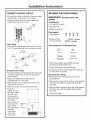
Read these instructions completely and carefuJJy.
Design Information
Models Available ..............................................................3
Cutout & Product Dimensions ........................................3
• iMPORTANT:
Save these instructions for local inspector's use.
Optional Accessories ......................................................3
Tools and Materials Required ......................................3
• iMPORTANT:
Observe all governing codes and ordinances.
Note to Installer - Be sure to leave these
instructions with the Consumer.
Installation
Advance Planning ............................................................4
Power Supply ....................................................................5
Remove Packaging ..........................................................5
Adjust Height of Icemaker ..............................................5
Water Supply ....................................................................6
Connect the Drain ............................................................6
• Note to Consumer
- Keep these instructions
with your Owner's Manual for future reference.
WARNING:
This appliance must be properly grounded.
Failure to do so can result in death, fire, or
electrical shock. See "Power Supply," page 5.
AVERTISSEMENT
Connect Water Supply ....................................................7
Reverse Door Swing ....................................................7, 8
:
Accessories
Cot appareil dolt 6tre correctement mis
la terre. Le non-respect de cos
instructions peut causer la mort, un
incendie ou un choc 61ectrique. Consulter
_ Alimentation 61ectrique _, page 5.
ZI P75WW, ZIP75BB Kit for 3/4" thick panels ........9, 10
If you received a damaged icemaker, you should
immediately contact your dealer or builder.
Proper installation is the responsibility of the installer.
Product failure due to improper installation is not
covered under the GE Appliance Warranty. See the
Owner's Manual for warranty information.
• Use this appliance only for its intended purpose.
Check with local utilities for electrical codes that apply
in your area. Local codes vary. Installation, electrical
connections and grounding must comply with
applicable codes. In the absence of local codes, the
icemaker should be installed in accordance with
National Electrical Code ANSI/NFPA 70-1990 or latest
edition.
For Monogram local service in your area, call
1.800.444.1845.
For Monogram Service in Canada, call
1.888.880.3830.
For Monogram Parts and Accessories, call
1.80&626.2002.
2
Design information
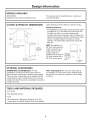
MODELS
AVAILABLE
ZDI15, ZDIS15
Available in black, white and stainless steel,
The icemaker may be installed below a countertop or
used free-standing.
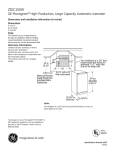
CUTOUT
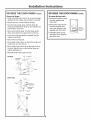
Cutout dimensions shown allow for a full door swing.
& PRODUCT
DiMENSiONS
Additional Clearances:
• The installation of a 3/4"thick custom panel will require
an additional 1-1/2"wide filler strip on the hinge side.
The filler strip will act as a spacer between the
icemaker case and an adjacent cabinet. The filler strip
will prevent interference with the icemaker door swing
when it is installed between frameless or framed
cabinetry. The width of the opening must include the
filler strip.
NOTE: The addition of a
"16-1/2" with a 3/4" thick
custom panel
3/4" thick front panel will
result in a front to back
34" min.
Adjustable
to 34-1/2"
depth of 24-1/16." The
product cannot be
installed flush to adjacent
24" deep cabinets with a
3/4"thick custom panel,
23-5/16"to
Door Front \
OPTIONAL
i¸
i
d
<
Factory set
\
forll OC'
door",
swing. Allow
",,,
2"min,towall 1102_
f°r90°d°°r
swing
\\\
.\,\
5-1/2" Minimum
to Wall
ACCESSORIES
ZIP75WW White and ZIP75BB BlackiFor
the
ZpKliDrain
Pump Kit. For use when a floor drain is
not available. The drain pump must be installed inside
the unit and can operate at a maximum vertical height
of 10 feet.
installation of a trimless 3/4" thick custom panel on
white and black models (not for stainless steel models).
This kit provides a handle that can be installed with the
custom panel. A custom handle of your choice may be
installed onto the 3/4" panel. See installation instructions
on pages 9 and 10.
TOOLS AND MATERIALS
REQUIRED
• 1/4" socket
• 3/4" adjustable wrench
,Level
• GE SmartConnect Refrigerator Tubing Kit or 1/4" O.D.
copper tubing, of sufficient length to reach the installation
TM
3
Installation instructions
ADVANCE
PLANNING
ADVANCE
CAUTION: Dueto
excessive
weight, TWO PEOPLEARE REQUIRED TO
MOVE AND iNSTALL THiS ICEMAKER.
Failure to do so can result in back or
other injury.
PLANNING
(cont.)
Before you begin:
1. If a custom panel is to be installed, follow the
instructions shown on pages 9 and 10.
-Order ZIP75 (black or white) panel kit.
-Order the custom panel from the cabinet
manufacturer.
-Secure the custom panel onto the icemaker.
IVliSE EN GARDE :
A cause de son poids eleve;JL FAUT
DEUX PERSONNES POUR DEPLACER ET
iNSTALLER CETTE MACHINE _, OLA_0NS.
Le non-respect de ces instructions peut
causer des biessures au dos ou d'autre
nature.
2. Determine a method of drainage. If a floor drain
is to be installed, the drain must be accurately
located. The installation of a custom door panel will
affectthe drain location. See page 6to determine
the exact location of the floor drain, front to back,
with or without a custom door panel.
-A drain pump kit, ZPK1, is available and will not
interfere with placement of the icemaker.
IMPORTANT:
The performance of the icemaker
may be affected when it is connected to a reverse
osmosis system. An RO system may reduce water
pressure and affectthe fill cycle, which is dependent
on time and flow. The reduced water pressure (less
than 30 p.s.i.) may cause the reservoir not to fill and
flush properly during the ice making cycle.
3. The door swing is reversible. If desired, change the
door swing before installation.
4. Slide the icemaker into the installation location.
-Open and close the door to be sure there is no
interference.
-Checkto be sure the icemaker can be moved
back into the opening, flush with adjacent
cabinetry. There should be no interference with
the floor drain.
* Do not use copper tubing when the icemaker is
connected to a reverse osmosiswater system.
Choose the location:
* Not designed for outdoor installation.
* The icemaker must be installed in an area protected
from elements such as wind, rain, water spray or drip.
The area should be ventilated with temperatures
above 55°F(13°0) and below 110°F(43°C). Best results
are obtained between 70°F (21%) and 90°F(32°0).
*The icemaker may be closed in on the top and
three sides as long as the front is unobstructed for
air circulation and proper operation.
-Installation should be such thatthe icemaker can
be moved forward for servicing, if necessary.
-The bottom grille on the front must be unobstructed
to provide proper air flow.
4
Installation instructions
POWER SUPPLY
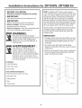
REMOVE
AND PARTS
• Lay the carton on rear face
and break open the bottom
flap.
WARNING:
FOR PERSONAL SAFETY,THIS
(PleaseAPPLIANCE
read carefully).
MUST BE PROPERLYGROUNDED. Failure to
follow these instructions can result in death,
fire, or electrical shock.
AVERTISSEMENT
PACKAGING
• Set the carton upright
with all four bottom flaps
outward.
:
• Lift carton up and off
icemaker.
(S'ilvous lisez avec soin).POUR VOTRE
SI_CURITI_,CETAPPAREIL DOlT f:TRE
CORRECTEMENT MIS A LA TERRE. Le
Open Bottom Flaps
• Remove all tape and
packaging material from the outside and inside
of the cabinet.
non-respect de ces instructions peut causer
la mort, un incendie ou un choc electrique.
• Locate parts package with plastic plug buttons.
Set aside.
Do not use an extension cord or adapter plug with
this appliance. Follow National Electrical Code or
prevailing local codes and ordinances.
This icemaker must be supplied with 115V,60Hz, and
connected to an individual, properly grounded branch
circuit, and protected by a 15 or 20 amp circuit breaker
or time delay fuse.
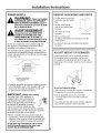
ADJUST
HEIGHT OF ICEMAKER
Height adjustments may be necessary to install
the icemaker below a countertop, and may be
accomplished by adjusting both the front and rear
leveling legs. The icemaker must be level to operate
properly.
Electrical Supply Should
Enter From Back Wall
In Shaded Area.
Raise
• A properly grounded three-prong receptacle should
be located within reach of the icemaker's 66" long
power cord. For a built-in installation, locate the
receptacle in the shaded area shown.
Lower
To level and adjust the height:
• With one person holding the icemaker, carefully tilt
the machine to access the leveling legs.
IMPORTANT:
(Please read carefully).
The power cord of this appliance is
equipped with a three-prong (grounding) plug that mates with a standard
three-prong grounding wall receptacle
to minimize the possibility of electric
shock. The customer should have the
wall receptacle and circuit checked by a qualified
electrician to make sure the receptacle is properly
grounded and has the correct polarity.
• Use an adjustable wrench to turn the legs.
-Turn legs right to lower, turn left to raise the
icemaker.
• Check top and side with a level. Continue adjusting
legs until the icemaker is level and stable.
• Where a standard two-prong wall receptacle is
encountered, it is the personal responsibility and
obligation of the customer to have it replaced with
a properly grounded three-prong wall receptacle.
Do not, under any circumstances, cut or remove
the third (ground) prong from the power cord.
DO NOT USE AN EXTENSION CORD.
5
InstalJation instructions
WATER SUPPLY
WATER SUPPLY (cont.)
* A cold water supply is required for icemaker
operation. The water pressure must be between
30 and 120 p.s.i.
• Install optional water filter in the water line near the
icemaker. A water filter is recommended in areas
where water supply contains sand or particles.
Installation instructions are packed with the filter.
IMPORTANT:
Water SupplyShould
Enter FromBack Wall
In Shaded Area.
* Route GE SmartConnect Kit or 1/4" O.D. copper
tubing between house cold water line and the water
connection location.
The performance of the icemaker
may be affected when it is connected to a reverse
osmosis system. An R.O. system may also reduce
water pressure and affect the fill cycle, which is
dependent on time and flow. The reduced water
pressure (less than 30 p.s.i.) may cause the reservoir
notto fill and flush properly during the ice making cycle.
• Do not use copper tubing when the icemaker is
connected to a reverse osmosis water system.
TM
The water line should be long enough to extend to the
back of the icemaker. Allow enough to accommodate
moving unit forward for service.
NOTE: The only GE approved plastic tubing is supplied in
the GE SmartConnect Refrigerator Tubing kits. Do not
use any other plastic water supply line because the line
is under pressure at all times. Other types of plastic may
crack or rupture with age and cause water damage to
your home. GE SmartConnect Refrigerator Tubing Kits
are available in the following lengths:
TM
TM
2'(0.6 m) WX08Xl0002
6' (1.8 m) WX08Xl0006
15'(4.6 m) WX08X10015
25' (7.6 m) WX08X10025
Shut off the main water supply
Turn on the nearest faucet long enough to clear the
line of water.
Install a shut-off valve between the icemaker water
valve and cold water pipe in a basement or cabinet.
The installation of an easily accessible shut-off valve
in the water line is required.
NOTE: It is best to install the valve into a vertical water
pipe. If you install the valve into a horizontal water
pipe, make the connection atthe top or side, rather
than at the bottom, to avoid drawing off any sediment
from the water pipe.
• Turn on the main water supply and flush debris from the
line. Run about a quart of water through the tubing into
a bucket. Shut off water supply at the shut-off valve.
NOTE: Saddle type shut-off valves are included in many
water supply kits, but are not recommended for this
application.
NOTE:Commonwealth of Massachusetts Plumbing
Codes 248CMR shall be adhered to. Saddle valves
are illegal and use is not permitted in Massachusetts.
Consult with your licensed plumber.
_6
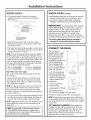
CONNECT
THE DRAIN
This icemaker is
equipped with a gravity
drain to prevent water
from flowing back into
the storage bin and
overflowing onto the floor.
The ideal installation
has a standpipe with a
2"to 1-1/2" PVC drain
reducer installed directly
below the drain tube:
-A 1" min. physical gap
between the bottom of
the icemaker drain hose
and the top of the house
drain is required. See
illustration.
/Drain Hose
1" Min. Gap
3-_-
Cu_om Panel
-7-1/2" to centerline
of the opening.
-Approximately 3-1/2" high.
LocateStandpipein exact
Centerof The Cutout
-22" from the front, or
22-3/4"when installing a 3/4" door panel.
• Drain lines must be at least 5/8" inside diameter.
NOTE: A drain pump is necessary when a floor drain
is not available. Order ZPK1 Drain Pump Kit or contact
your local plumber for a recommended pump available
in your area.
TEST DRAIN HOSE ALIGNMENT: Before sliding the
icemaker into the cabinet opening, check to be sure
the bottom of the drain tube is below the rear cover.
To test, place a pan belowthe drain hose. Pour a
gallon of water into the ice bin and check to be sure
that water does not wet the rear cover.
Installation instructions
CONNECT
WATER SUPPLY
REVERSE THE DOOR SWING
* The water line should be flushed to clear any foreign
material before connecting to the icemaker.
IMPORTANT:
* Connect the water line to the water supply tube
outside of the rear access cover.
Tools Required:
Water
//
I
• 1/4" and 5/16"wrench
• Flat putty knife
Line
o
Disconnect power to the
icemaker.
@Supply
• Phillips screwdriver
Parts Supplied:
• 4 plug buttons
• 4 hinge screws
(on some models)
Copper Tubing:
* Use a standard plumbing female connector or union
for 1/4" copper tubing that can be purchased locally.
Coupling
(NotS@plied)
Parts Identification: (For Reference 0nly)
Hinge Pin
Handle Screw
5/16" Hex Head
Hinge Screw
Endcap Screw
Nut
(Supplied)
\
\
Nut
(Supplied)
Lineto
Icemal(er
• Remove the handle screws and lift off handle.
(On black and white models only.)
Ferrule
(Not Supplied)
• Remove the hinge pin from the top hinge.
GE SmartConnect'=Tubing:
* Insert the molded end of the tubing intothe icemaker
connection. Tighten the compression nut until it is
just hand tight.
* Tighten one additional turn with a wrench.
Overtightening can cause leaks!
* Make sure there are no sharp bends or kinks that
could restrict water flow.
* Slide the icemaker into its permanent location.
leaks. Tighten
any connections
(including
connections
atthe valve)
if necessary.
Reverse the door endcaps:
• Remove the screws and endcaps from the door,
top and bottom.
• Place the top endcap onto the bottom of the opposite
side of the door with the long flat side facing the
door front.
• Place the bottom endcap onto the top of the opposite
side of the door, with the long flat side facing the
door front.
* To prevent
rattling, be sure
the copper tubing
does not touch
the side wall or
other parts inside
the cabinet.
* Open the shut-off
valve. Check for
• Lift the door off of the bottom hinge. Place the hinge
pin back into the top hinge.
• Setthe door aside.
Water Pan
Water Valve -
5-11/16"
4-5/8"
Installation instructions
REVERSE THE DOOR SWING
(cont.}
Reverse the hinges:
• Using a flat putty knife, remove the screw hole plugs
opposite the door hinges, top and bottom. Set aside.
• Remove the two screws holding top hinge.
• Turn the hinge upside down, with the hinge pin
pointing up. Reinstall the hinge on the opposite side
at the bottom of the door.
Remove the bottom hinge. Turn the hinge upside
down and install on the opposite side atthe top.
• Push screw hole plug buttons (supplied) into the
original screw holes.
Remove the top hinge pin.
Place plastic hinge sleeve on the bottom hinge and
position the door onto the pin.
• Place plastic hinge sleeve in the top hinge hole on
the door. Align the door on the bottom hinge and
replace top hinge pin.
Reinstall handle with original screws.
Top Hinge
_
Hinge Pin
Hinge Sleeve/
Door Stop
Hex Head Hinge Screw
BottomHinge
"O
Phgs_
"_
""" ""_-'_
Hex Head
_
J
Hinge Screw
" 22eS'
eve/
J
Hin_
_"--Hinge
Pin
Top Hinge
Bottom Hinge
_8
REVERSE THE DOOR SWING
(cont.)
To reverse the door catch:
• Remove the plastic screws
from the opposite side
of the door.
• Remove the metal screws
from the magnetic door
catch and reinstall on the
opposite side of the door.
• Install the plastic screw
into place on the opposite
side of the door.
Reverse
Door Catch
Position
I
Installation instructions for ZIP75WW, ZIP75BB Kit
• BEFORE YOU BEGIN:
NOTE: If installing a 3/4"trimless custom panel, a
1-1/2"wide filler strip may be required. The filler strip
will act as a spacer between the icemaker case and
the adjacent cabinet, and will prevent interference
with the icemaker door swing when it is installed
between frameless or framed cabinetry. The width of
the cutout opening must include the width of the filler
strip. The product cannot be installed flush to adjacent
24" deep cabinets with a 3/4" thick custom panel.
Read these instructions completely and carefuJJy.
• iMPORTANT:
Save these instructions for local inspector's use.
• iMPORTANT:
Observe all governing codes and ordinances.
• Note to InstaflerBe sure to leave these
instructions with the Consumer.
This kit contains a new handle and two side mounting
brackets to support a trimless custom door panel
up to 3/4"thick. A custom handle may replace the
supplied handle.
• Note to Consumer
- Keep these instructions with
your Owner's Manual for future reference.
WARNING:
Disconnect electrical power supply to
icemaker before installing front panel. Do not
operate icemaker while installing panel.
Failure to do so can result in death, fire, or
electrical shock.
iMPORTANT:
AVERTJSSEMENT
* The custom panel, both raised and flat design,
should be constructed in the same manner as typical
cabinet doors.
* Cut edges of the custom door panel will be seen and
must be finished for best appearance. The back side
ofthe panel should be finished a minimum of 1/2"
on all sides.
:
II faut debrancher ralimentation de la
machine _ gla£ons avant d'installer le
panneau avant. La machine _ gla_ons ne
doit pas _tre en marche pendant rinstallation
du panneau avant. Le non-respect de cos
instructions peut causer la mort, un incendie
ou un choc 61ectrique.
* Order the custom panel from the cabinet manufacturer.
Be sure to provide the exact dimensions so that the
panel is constructed accurately.
Kit Contents:
LeflTdm
* 2 side trim pieces
* 8 side trim screws
* Door handle
Tools and Materials Required:
•, 8 flat head wood screws, 1/2" long
29 1/2" I
Custom
Panel
• Drill and 1/8" bit
• Safety glasses
J
*Tape
\ RightTrim
• Custom panel
14_23/32"
9
Installation instructions for ZIP75WW, ZIP75BB Kit
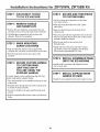
STEP 5
TO THE iCE MACHINE
SECURE SIDE TRIM PIECES
TO CUSTOM PANEL
• Lay the custom panel appearance-side-down
on a clean surface.
STEP 2
REMOVE HANDLE
AND NAMEPLATE
• Align top and bottom side trim to the custom
panel sides.
• Remove the door handle by removing the two top
mounting screws. Set screws aside, Discard handle.
• Tape the side trim pieces to the back of the
custom panel,
• The Monogram nameplate is held in place with
adhesive. Remove the nameplate.
• Place the panel with trim against the door to be sure
that trim and panel fits the door side to side and top
to bottom. Adjust as needed.
STEP 3
• Mark screw locations and remove trim.
MARK MOUNTING
SCREW LOCATIONS
Drill pilot holes.
• Install side trim to the back side of the custom
• Align and hold the side trim pieces against the
icemaker door and mark screw locations on the sides.
panel with screws (not supplied). Use flat head
wood screws approximately 1/2" long,
• Drill 1/8" pilot holes into the door sides of the
icemaker.
STEP 6
STEP 4 SECURE CUSTOM HANDLE
TO CUSTOM PANEL.
(SKIP THIS STEP IF
YOU ARE USING THE
SUPPLIED HANDLE)
INSTALL ASSEMBLED PANEL
ONTO THE ICE MACHINE
• Install panel to icemaker with supplied screws,
four on each side.
STEP 7
A custom handle can be installed onto the 3/4"thick
panel, replacing the supplied handle.
INSTALL SUPPLIED DOOR
HANDLE (IF USED)
• Install the new supplied handle with original screws.
• The custom handle can be installed at the top or side
of the panel.
• Drill pilot holes through the front of the custom panel
to match the chosen handle.
• Secure the handle to the panel with flat head wood
screws.
• Replace original handle screws in the top of the door
frame,
10
Notes
11
NOTE:While performing installations described in this book,
safety glasses or goggles should be worn.
]l))F
o
,_lO?tO_'Yaltt
oo
[0(:(1[ ,_(_-Uit:( _ i?t 30_tT
(/?'('(/,
c(l[I
l ._00. 444. l,_4 _.
NOTE:
al
and
I) vodu(:l
( enel-al
Ele(lri(.
Sl)e(ifi(aliol_S
inll)rov(*nlenl
is a continuing
Thel-et_n-e,
_11(_ stl|)i(..1
malel-ials,
lo
(hange
endeavor
al)l)earal_(e
wilhoul
noli(e.
Monogram:
Pub.No. 49-60016-4 ]
PartNo. 197D2522PO01
]
2217409
02-06JR
Printedin tl_e United States
GE Col_sumer& Industria /
GEAppliancos
Gotle_] Electric _mpang
Louisdlle, KY40225
go com
©2000 GE Compmly