1
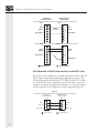
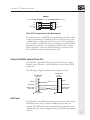
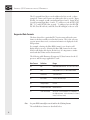
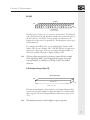
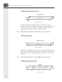
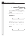
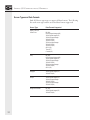
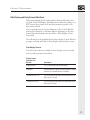
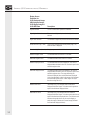
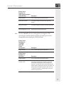
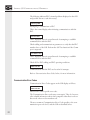
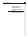
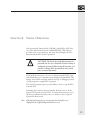
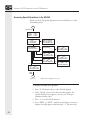
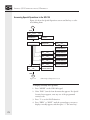
Publication 0300129-02 Rev. C SIEMENS (S5 Communications) Reference IMPORTANT NOTES 1. READ ALL OF THE INFORMATION CONTAINED IN THIS MANUAL BEFORE YOU INSTALL THE PRODUCT. 2. The information contained in this manual applies to hardware and software version 1.0 or later. 3. This manual assumes a full working knowledge of the relevant programmable controller. NOTICE The products and services described in this manual are useful in a wide variety of applications. Therefore, the user and others responsible for applying the products and services described herein are responsible for determining their acceptability for each application. While efforts have been made to provide accurate information within this manual, Spectrum Controls assumes no responsibility for the accuracy, completeness or usefulness of the information contained herein. Under no circumstances will Spectrum Controls be responsible or liable for any damages or losses, including indirect or consequential damages or losses, arising out of either the use of any information contained within this manual or the use of any product or service referenced herein. No patent liability is assumed by Spectrum Controls with respect to the use of any of the information, products, circuits, programming or services referenced herein. The information contained in this manual is subject to change without notice. Caution Spectrum Controls’ devices contain electronic components which are susceptible to damage from electrostatic discharge. A static charge can accumulate on the surface of ordinary plastic wrapping or cushioning material. If any Spectrum Controls’ device must be returned to Spectrum Controls, the following packaging instruction must be followed: PREFERRED: Use the original packaging material as supplied by Spectrum Controls. Place the device inside the conductive plastic bag. ACCEPTABLE: Wrap the device in some type of antistatic material. Antistatic plastic material can be identified by its pink color, and can be obtained in sheet or bag form. UNACCEPTABLE: Do not use ordinary plastic film, foam, or styrene chips (“popcorn” or “peanuts”). These materials can accumulate charges in excess of 10,000 volts, resulting in possible damage to the Spectrum Controls electronic device. Antistatic (metallized plastic) bags can be obtained from the following manufacturers: 3M Company Static, Inc. Charles Water (800-328-1368) (800-782-8424) (617-964-8370) Type 2100 bag 8000 Series bag CP-303 bag LIMITED WARRANTY Spectrum Controls warrants that its products are free from defects in material and workmanship under normal use and service, as described in Spectrum Controls literature covering this product, for a period of 1 year. Spectrum Controls’ obligations under this warranty are limited to replacing or repairing, at its option, at its factory or facility, any product which shall, in the applicable period after shipment, be returned to Spectrum Controls’ facility, transportation charges prepaid, and which after examination is determined, to the satisfaction of Spectrum Controls, to be thus defective. This warranty shall not apply to any such equipment which shall have been repaired or altered except by Spectrum Controls or which shall have been subject to misuse, neglect or accident. In no case shall Spectrum Controls’ liability exceed the purchase price. The aforementioned provisions do not extend the original warranty period of any product which has either been repaired or replaced by Spectrum Controls. Copyright and Trademark information: SOI, SOI-SPS, and SOI-PRO are trademarks of Spectrum Controls, Inc. IBM is a registered trademark of International Business Machines Corporation. MS-DOS is a registered trademark of Microsoft Corporation. SIMATIC is a registered trademark of Siemens AG. All other trademarks belong to their respective owners. © 1999 Spectrum Controls, Inc. All rights reserved. CONTENTS CHAPTER 1: COMMUNICATIONS ........................................ 1 Using the Communications Port .................................... 1 Using the SOI-260’s Optional Printer Port..................... 3 ASCII Input ................................................................... 3 Special Switch Settings ................................................... 4 CHAPTER 2: PROGRAMMING ............................................. 5 Supported Operand Types .............................................. 5 Supported Data Formats................................................. 6 Screen Types and Data Formats .................................... 12 Data Display and Entry Screen Definitions .................. 13 SOI Configuration Data Menu .................................... 19 CHAPTER 3: TROUBLESHOOTING .................................... 21 General Symptoms and Solutions ................................. 21 Communication Error Codes ....................................... 22 CHAPTER 4: SPECIAL OPERATIONS ..................................25 Accessing Special Operations in the SOI-260 ............... 26 Accessing Special Operations in the SOI-120 ............... 28 INDEX ............................................................................... 31 CHAPTER 1: COMMUNICATIONS CHAPTER 1: COMMUNICATIONS This chapter of the Siemens (S5 Communications) Reference concerns: the cabling needed to use the SOI-120 or SOI-260 Communications Port and the SOI-260’s optional Printer Port, using the SOI-260’s optional Printer Port with ASCII input devices (including bar code scanners), and special PLC and SOI switch settings. Using the Communications Port The communications port may be used for up/downloading application programs or communicating with the PLC. The following illustrations identify cable pin-outs for SOI-to-computer communications, Spectrum Controls’ SCC-3 up/download cable (including adapters), and SOI-to-PLC communications. SOI Upload/Download Cable Requirements The illustration below shows the up/download cable pin-out configuration for the communications port (RS-232 selected). The diagram indicates the required connections when building your own cable. 1 SIEMENS (S5 COMMUNICATIONS ) REFERENCE SOI RS-232 Communications Port Computer Serial Port (COM1, COM2) 9 pin: Data In Data Out Signal Ground 9 pin: 9 pin: Data In Data Out Signal Ground 1 2 3 4 5 6 7 8 9 1 2 3 4 5 6 7 8 9 Data In Data Out Signal Ground 25 pin: 1 2 Data Out 3 Data In 4 5 6 7 Signal Ground 8 25 1 2 3 4 5 6 7 8 9 Male Connector Female Connector SOI Up/Download via RS-232 Communication Port with SCC-3 Cable If you don’t want to build your own cable, Spectrum Controls offers the SCC-3 cable for uploading/downloading application programs. The following illustrations describe the SCC-3 cable. Use the SCC-3 cable to connect the RS-232 communication port of the SOI to a personal computer for transferring application programs. A 9-to-25 pin adapter may be required if your computer has a 9-pin communication port. SCC-3 SOI RS-232 Communications Port 9 pin: 1 Data in 2 Data Out 3 4 Signal Ground 5 Male Connector 2 Computer Serial Port (COM1, COM2) 25 pin: 1 2 Data Out 3 Data In 4 7 Signal Ground Female Connector CHAPTER 1: COMMUNICATIONS Adapter 25-Pin Male Connector TXD RXD Signal Ground DTR 2 3 7 20 9-Pin Female Connector 3 2 5 4 TXD RXD Signal Ground DTR SOI-to-PLC Communications Cable Requirements For communications, a SIMATIC S5 programmable controller contains a single programming port (which may also be used for point-to-point communications, as supported by the S5 protocol). The programming port is a female 15-pin D-sub connector configured as a serial digital 20 mA current loop interface. To communicate with the SOI, a special cable is required to convert the 20 mA current loop serial data to the RS-232 levels that can be interpreted by the SOI. Using the SOI-260’s Optional Printer Port The SOI-260's optional RS-232 printer port may be used to output Printer Forms to a Printer or other serial device, such as a large ASCII display unit. The following configuration illustrates the cabling to be used. SOI-260 RS-232C Printer Port Data Out Signal Ground Request to Send Clear to Send 1 2 3 4 5 6 7 8 9 Female connector RS-232C Printer or other Serial Device 1 2 3 4 5 6 7 8 9 Data In Signal Ground Request to Send Clear to Send Male connector ASCII Input The SOI-260’s optional RS-232 printer port may also be used to accept ASCII data from a variety of devices, including decoded bar code scanners. The ASCII data can be entered directly from the device into a standard data entry screen (configured using the SOI-SPS programming software). 3 SIEMENS (S5 COMMUNICATIONS ) REFERENCE Note If an odd number of characters is received from the scanner, a Null character is added to create an even byte count. This facilitates word writes to the controller. If keypad entry is enabled, the operator may also enter the decimal equivalent of an ASCII character in the data entry field. For example, an operator can manually enter 2 characters and then scan a bar code containing 8 characters. The SOI then writes all 10 characters to the controller. The SOI writes data to the controller on receipt of an ASCII carriage return or when the RETURN key is pressed. Special Switch Settings The SIMATIC S5 programmable controller does not require any special DIP switch or other switch settings to establish communications with the SOI. The SOI communications parameters (baud rate, data bits, and parity) must match that of the S5 processor, but unless you have changed these parameters in the S5 processor, you should not have to reset anything: the default SOI settings match those of the S5 processor. The SOI DIP switch settings are described in the SOI-120 and SOI-260 Operator Interface User Manuals. 4 CHAPTER 2: PROGRAMMING CHAPTER 2: PROGRAMMING This chapter of the Siemens (S5 Communications) Reference addresses supported PLC registers and data formats, screen types and definitions, and PLC-specific configuration requirements. Supported Operand Types The SOI supports the following operand types in your S5 processor: Note: Operand Definition Address Range Allowed Data Formats I (IW, IB) Inputs 128 bytes (0-127) KH, KM, KF, KS, KB Q (QW, QB) Outputs 128 bytes (0-127) KH, KM, KF, KS, KB F (FW, FY) Flags 256 bytes (0-255) KH, KM, KF, KS, KB T Timers 128 words (0-127) KT, KM C Counters 128 words (0-127) KC, KM DW Data Words 256 words (0-255) KH, KM, KF, KS, KB The S5 operands listed above are a subset of the operands defined by the S5 protocol. Thus, some of the operands used by high-end and low-end SIMATIC S5 controllers are not supported by this protocol implementation. 5 SIEMENS (S5 COMMUNICATIONS ) REFERENCE The S5 operands listed above can be addressed as bits, words, or bytes (exception: Timers and Counters are addressed as bits or words). Input Word 0, for example, would contain Input Bytes 0 and 1. Input Word 1 would contain Input Bytes 1 and 2. To address a word, the IW, QW, FW, T, C, and DW ID codes are used. To address a byte, the IB, QB, FY, DL (Data Word Left), and DR (Data Word Right) codes are used. Supported Data Formats The data selected for a particular PLC location must reflect the same format as the data actually stored in that location. This is the only way you can ensure that correct, consistent information is displayed on the SOI products. For example, selecting the Hex (KH) format for one location will display data in one way. Selecting the Byte (KB) format for the same location will display the data in another way. It is important to understand each data format and its characteristics. The following table illustrates all supported S5 data formats for the S5 processor and the ranges applicable to each: Note: Data Format Definition Range KM Bits 0000 0000 0000 0000 to 1111 1111 1111 1111 KH Hex Binary 0000 to FFFF, or BCD 0000 to 9999 KF Fixed Point -32768 to 32767 KS ASCII Data 1 ASCII character / byte KB Unsigned Byte 0 to 255 KC Counter Load Value 000 to 999 BCD KT Timer Load Value abc.d, abc = count 0-999BCD, d = timebase 0-3 (0= 0.01 sec/count, 1= 0.1 sec/count, 2= 1.0 sec/ count, 3= 10 sec/ count) See your PLC manual for more detail on the S5 data formats. The available data formats are described below. 6 CHAPTER 2: PROGRAMMING Bit (KM) Bit Data MSB 15 14 13 12 11 10 9 8 7 6 5 4 3 2 1 0 LSB 16 individual bits (One 16-bit location) The PLC stores a binary (0 or 1) status for a bit location. The SOI will read a PLC bit location and determine whether the operational status of the bit is ON (1) or OFF (0). You can specify associated text to be displayed for either state of a specified bit. This description can be up to twenty characters. For example, the OFF(0) state of a bit might display “Pump is OFF,” and the ON (1) state “Pump is ON.” SOI-SPS allocates enough screen characters for the longest of the two text strings. In this example, 11 characters would be allocated to display “Pump is OFF.” Note: The fewer characters used, the less memory is required. In the example above, displaying "OFF" (given the appropriate context) conveys the same information in 3 characters as "Pump is OFF" does with 11 characters. 8-Bit Unsigned Integer (Byte, KB) 8-Bit Unsigned Integer MSB 8-Bit Data Field Bit 7 LSB Bit 0 Range = 0 to +255 This data format displays a 8-bit register as an Unsigned Integer value. It represents a positive number by using the 8th bit as a data bit rather than a sign bit. The 8-bit Unsigned Integer values have a range of 0 to +255. Note: This data format may be scaled to different engineering units. 7 SIEMENS (S5 COMMUNICATIONS ) REFERENCE 16-Bit Signed Integer (Fixed Point, KF) 16-Bit Signed Integer MSB 15-Bit Data Field LSB Bit 15 (sign bit) Bit 0 Range = -32768 to +32767 This data type displays a 16-bit register as a signed Integer (two’s complement) value. The 16th bit of the register is the sign bit and is set (1) for a negative and cleared (0) for a positive number. The 16-bit signed integer values have a range of -32768 to +32767. Note: This data format may also be scaled to different engineering units. 16-Bit Unsigned Integer 16-Bit Unsigned Integer MSB 16-Bit Data Field LSB Bit 15 Bit 0 Range = 0 to +65535 This data format displays a 16-bit register as an Unsigned Integer value. It represents a positive number by using the 16th bit as a data bit rather than a sign bit. The 16-bit Unsigned Integer values have a range of 0 to +65,535. Note : This data format may also be scaled to different engineering units. 16-Bit Binary Coded Decimal (KH) 16-Bit BCD MSB Digit 4 Bit 15 Digit 3 Bit 12 Bit 11 Digit 2 Bit 8 Bit 7 Range = 0 to 9999 8 Digit 1 Bit 4 Bit 3 LSB Bit 0 CHAPTER 2: PROGRAMMING This data type displays a 16-bit register location as a 4-digit Binary Coded Decimal value. The range for the 16 bit BCD selection is 0 to +9999. Note: This data format may also be scaled to different engineering units. 16-Bit Hexadecimal (KH) 16-Bit HEX MSB Digit 4 Bit 15 Digit 3 Bit 12 Bit 11 Digit 2 Bit 8 Bit 7 Digit 1 Bit 4 Bit 3 Bit 0 LSB Range = 0 to FFFF This data type displays a 16-bit register location as a 4-digit hexadecimal value. The range for the 16-bit Hex format is 0 to +FFFF. The Hexadecimal number system is defined as a base of 16 (0-9 and the characters A, B, C, D, E, F). Note: This data format may not be scaled to different engineering units. It is used for display-only (non-entry) operations. 32-Bit Unsigned Integer 32-Bit Unsigned Integer MSB 16-Bit Location #1 16-Bit Location #2 (next sequential location) LSB Range = 0 to 4,294,967,295 This data format displays data located in two consecutive 16-bit register locations as a 32-bit Unsigned Integer. It uses a memory register plus the next higher register to form the 32-bit location. The High data value is stored in the first register and the Low data value is stored in the next sequential register location. The range for the 32-bit unsigned Integer value is 0 to +4,294,967,295. Note: This data format may not be scaled to different engineering units. 9 SIEMENS (S5 COMMUNICATIONS ) REFERENCE 32-Bit Binary Coded Decimal (KH) 32-Bit BCD MSB 16-Bit Location #1 16-Bit Location #2 (next sequential location) LSB Range = 0 to 99,999,999 This data type displays two consecutive 16-bit register locations as a 32bit BCD value. It uses a memory register plus the next higher register to form the 32 bit location. The range for the 32 bit BCD value is 0 to +99,999,999. Note: This data format may not be scaled to different engineering units. 32-Bit Hexadecimal (KH) 32-Bit HEX MSB 16-Bit Location #1 16-Bit Location #2 (next sequential location) LSB Range = 0 to FFFF FFFF This data type displays two consecutive 16-bit register locations as a 32bit Hex value. It uses a memory register plus the next higher register to form the 32-bit location. The range for the 32-bit HEX value is 0 to FFFF FFFF. Note: This data format may not be scaled to different engineering units. This data format is used for display-only (non-entry) operations. ASCII (KS) ASCII Data Field MSB 8-Bit Location #1 8-Bit Location #2 (next sequential location) CHR #1 10 CHR #2 LSB CHAPTER 2: PROGRAMMING Each 16-bit location may contain two ASCII characters (1 byte each). By default, the most significant byte of the base address stores the first character, the least significant byte stores the second character, the first byte of the next sequential location stores the third character, and so on. The data held in this range of address locations is expected to be an ASCII data format. Note: The ASCII data format is very useful for PLC applications reading ASCII data from bar code readers or data collection terminals. Timer (KT) 16-Bit Timer MSB Bit 15 Timebase Bit Bit 13 12 Value Bit 11 Bit 10 Bit 9 LSB Bit 0 Range = 000.0 to 999.d This data type displays the first 10 bits of a 16-bit register location as a 3-digit (decimal) unsigned integer. The range for the Timer selection is 000.0 to +999.d, where d is the timebase (0 = 0.01 sec/count, 1 = 0.1 sec/count, 2 = 1.0 sec/count , and 3 = 10 sec/count). Timebase d is found in Bits 12 and 13. Note: This data format may not be scaled to different engineering units. Counter (KC) 16-Bit Counter MSB Value Bit 15 Bit 10 Bit 9 LSB Bit 0 Range = 0 to 999 This data type displays the first 10 bits of a 16-bit register location as a 3-digit (decimal) unsigned integer. The range for the Counter selection is 0 to +999. Note: This data format may not be scaled to different engineering units. 11 SIEMENS (S5 COMMUNICATIONS ) REFERENCE Screen Types and Data Formats Each SOI Screen type may not support all data formats. The following lists each screen type and the associated data formats supported. Screen Type Display, Alarm, & Printer Form 12 Data Formats Supported Bit (KM) 8-Bit Unsigned Integer (KB) 16-Bit Signed Integer (KF) 16-Bit Unsigned Integer 16-Bit BCD (KH) 16-Bit HEX (KH) 32-Bit Unsigned Integer 32-Bit BCD (KH) 32-Bit HEX (KH) ASCII (KS) Timer (KT) Counter (KC) Entry Bit (KM) 8-Bit Unsigned Integer (KB) 16-Bit Signed Integer (KF) 16-Bit Unsigned Integer 16-Bit BCD (KH) 32-Bit Unsigned Integer 32-Bit BCD (KH) ASCII (KS) Bargraph 16-Bit Signed Integer (KF) 16-Bit BCD (KH) Recipe 16-Bit Signed Integer (KF) 16-Bit Unsigned Integer 16-Bit BCD (KH) 32-Bit Unsigned Integer 32-Bit BCD (KH) Background Monitor Bit (KM) 16-Bit Signed Integer (KF) 16-Bit BCD (KH) CHAPTER 2: PROGRAMMING Data Display and Entry Screen Definitions When programming Data Display and Data Entry fields and positioning them on the SOI display, each field must be defined according to its PLC location, data format, and other data parameters specific to the data format selected. You are prompted for the register definitions at the Control Window. Each register definition is somewhat different, depending on the data format selected and whether the data field is a Data Display or Data Entry field. The following lists the applicable data formats and the Control Window prompts associated with each for Data Display and Data Entry screens. Data Display Screens The data format selections available for Data Display screens are listed below and their parameters described. Display Screen Parameter for: Bit Data Description Register Number The PLC data location operand and address. Bit Number The Bit number if the register number designates a multiple bit location (a 16 bit data address, for example). Text when Bit is OFF (0) The 20 character text description to be displayed when the bit is in an OFF (0) state Text when Bit is ON (1) The 20 character text description to be displayed when the bit is in an ON (1) state. 13 SIEMENS (S5 COMMUNICATIONS ) REFERENCE 14 Display Screen Parameter for: 16-Bit Unsigned Integer, 8-Bit Unsigned Integer, 16-Bit Signed Integer & 16-Bit BCD Data Description Register Number The PLC data location operand and address. Digits Right of Decimal The number of digits to be placed to the right of the decimal. Digits Left of Decimal The number of digits to be placed to the left of the decimal. Leave Place for Sign (Y or N) Leave a one character place for the polarity sign (+ or -) when the data is displayed. Show Leading Zeros (Y or N) Display any zeros to the left of the data. Minimum Register Value The minimum data value of the PLC location. Maximum Register Value The maximum data value of the PLC location. Minimum Displayed Value The minimum data value to be displayed. This value is displayed when the data in the PLC location is equal to the minimum register value. Maximum Displayed Value The maximum data value to be displayed. This value is displayed when the data in the PLC location is equal to the maximum register value. The range defined by the Minimum Displayed Value and the Maximum Displayed Value is proportionally scaled to the range of the minimum and maximum register values. If both ranges are equal then the scaling ratio is 1:1. Minimum Bar Value (Bar Graph Only) The minimum value of data to be displayed in the Bar Graph. This value must be greater or equal to the Minimum Displayed Value. Maximum Bar Value (Bar Graph Only) The maximum value of data to be displayed in the Bar Graph. This value must be less than or equal to the Maximum Displayed Value. The Minimum and Maximum bar graph values may be used to display a particular range or window of an overall range (Minimum and Maximum Displayed Values). CHAPTER 2: PROGRAMMING Display Screen Parameter for: 32-Bit Unsigned Integer & 32-Bit BCD Data Description Register Number The PLC data location operand and address. Digits Right of Decimal The number of digits to be placed to the right of the decimal. Digits Left of Decimal The number of digits to be placed to the left of the decimal. Show Leading Zeros (Y or N) Display any zeros to the left of the data. Note : For the 32-Bit BCD selections, scaling of data is not supported. The selected register number and the next higher sequential register number identify the locations defining the 32 bit data value. Display Screen Parameter for: 16 -Bit HEX, 32-Bit HEX, Timer & Counter Data Description Register Number The PLC data location operand and address. Display Screen Parameter for: ASCII Data: Description Register Number The PLC data location operand and address. Character Count The number of characters (2 characters for each 16 bit data location) to be displayed, up to a maximum of 20 characters. The initial byte of the location identified by the register number is displayed first, then the second byte, the first byte of the next higher sequential location, and so on. To display 20 characters, a sequential block of ten 16 bit locations is read by the SOI. 15 SIEMENS (S5 COMMUNICATIONS ) REFERENCE Data Entry Screens The data format selections available for Data Entry screens are listed below and their parameters described. Entry Screen Parameter for: Bit Data Description Register Number The PLC data location operand and address. Bit Number The Bit number if the register number designates a multiple bit location (a 16 bit data address, for example). This selection is irrelevant if the register number refers to a Bit type address. Input Data by Pressing ‘1’/’0' or ‘Y’/’N’ ? (Enter 1 or Y) This parameter determines whether the operator will enter 1 or Y to set the defined bit location. If 1 is entered, 0 will clear the bit location. If Y is entered, N will clear the bit location. Default Value ? Z = No Default (Enter 1,0,Y,N,Z) 16 This parameter defines the default value that is displayed at the data entry position of the SOI display. If a default value of Y is entered, a Y is displayed, and the operator is only required to press ENTER to set the bit location. An entry of Z defines no default value. If there is no default value programmed, and the operator presses the ENTER, no data is sent to the PLC. CHAPTER 2: PROGRAMMING Entry Screen Parameter for: 16-Bit Unsigned Integer, 8-Bit Unsigned Integer, 16-Bit Signed Integer & 16-Bit BCD Data Description Register Number The PLC data location operand and address. Digits Right of Decimal The number of digits to be placed to the right of the decimal. Digits Left of Decimal The number of digits to be placed to the left of the decimal. Leave Place for Sign (Y or N) Leave a one character place for the polarity sign (+ or -) when the data is displayed. Minimum Register Value The minimum data value of the PLC location. Maximum Register Value The maximum data value of the PLC location. Minimum Entry Value The minimum data value to be entered. When this value is entered the minimum register value is entered to the defined PLC location. Maximum Entry Value The maximum data value to be entered. When this value is entered the maximum register value is entered to the defined PLC location. The range defined by the minimum entry value and the maximum entry value is proportionally scaled to the range of the minimum and maximum register values. If both ranges are equal then the scaling ratio is 1:1. Low User Input Limit The minimum entry value that an operator may enter. This value must be within the minimum and maximum entry values. If a value lower than this limit is entered the SOI will display an “Input Error” screen displaying the minimum and maximum entry limits. High User Input Limit The maximum entry value that an operator may enter. This value must be within the minimum and maximum entry values. If a value higher than this limit is entered the SOI will display an “Input Error” screen displaying the minimum and maximum entry limits. Default Value This parameter defines a default value that is displayed at the entry location of the display. An entry of Z defines no default value. 17 SIEMENS (S5 COMMUNICATIONS ) REFERENCE Entry Screen Parameter for: ASCII Data Description Register Number The PLC data location operand and address. Character Count The number of characters (2 characters for each 16 bit data location) to be displayed, up to a maximum of 20 characters. The initial byte of the location identified by the register number is displayed first, then the second byte, the first byte of the next higher sequential location, and so on. To display 20 characters, a sequential block of ten 16 bit locations is read by the SOI. Entry Screen Parameter for: 32-Bit Unsigned Integer & 32-Bit BCD Data Description Register Number The PLC data location operand and address. Digits Right of Decimal The number of digits to be placed to the right of the decimal. Digits Left of Decimal The number of digits to be placed to the left of the decimal. Low User Input Limit The minimum entry value that an operator may enter. This value must be within the range of 0 to +99,999,999. If a value lower than this is entered, the SOI will display an “Input Error” screen displaying the minimum and maximum entry limits. High User Input Limit The maximum entry value that an operator may enter. This value must be within the range of 0 to +99,999,999. If a value higher than this is entered, the SOI will display an “Input Error” screen displaying the minimum and maximum entry limits. Default Value This parameter defines a default value that is displayed at the entry location of the display. An entry of Z defines no default. Note : For the 32-Bit BCD selections, scaling of data is not supported. The defined register number and the next higher sequential number locations will define the data value. 18 CHAPTER 2: PROGRAMMING SOI Configuration Data Menu This section describes the PLC-specific requirements that the SOI-SPS programming software supports. The programming information may be found at the SOI Configuration Data Menu in the SOI-SPS software. Note: Refer to the SOI-SPS programming software manual for complete details on programming and additional information regarding the SOI configuration Data Menu. In addition, refer to the Siemens PLC operations manual for details on the specific PLC you are working with. Time Synchronization The Real Time Clock of the SOI-260 may either be written to the PLC or synchronized with the PLC by utilizing the Write Time or Read Time selections, respectively. These selections are located after selecting the Time Synchronization selection from the SOI Configuration Data menu. The Real Time Clock data will be written to the PLC in a batch of eight byte registers. A base register is defined as the first of eight bytes to hold the clock data. These eight byte registers contain data as follows: Base Unused Base +1 Day of Week, 1-7 (Sunday=1) Base +2 Day of Month, 1-31 Base +3 Month, 1-12 Base +4 Year, tens and units (e.g., 1995=95) Base +5 Hour, 0-23 Base +6 Minutes, 0-59 Base +7 Seconds, 0-59 The clock data will be synchronized on a 60-69 second interval. These eight locations should not be the actual clock location of the PLC as the SOI is not setting the PLC clock itself but simply providing a clock source to the PLC at a certain location. 19 SIEMENS (S5 COMMUNICATIONS ) REFERENCE Communications Port Setup To define the Communications Port Parameters, select SOI Configuration Data from the Edit File - Option Selection menu. At the SOI Configuration Data menu, select the PLC Hardware Parameters item. The baud rate, data bits, and parity information must be entered to match the respective settings of the S5 processor. The Communications Port parameters have the same default values as the S5 processor: 20 Baud Rate: 9600 Data Bits: 8 Parity: Even CHAPTER 3: TROUBLESHOOTING CHAPTER 3: TROUBLESHOOTING This chapter of the Siemens (S5 Communications) Reference provides solutions to possible operational problems with the SOI and its use with the Siemens S5 processor. Also contained is a description of the Communication Error Codes specific to the S5 communication protocol used for the S5 processor and the SOI. General Symptoms and Solutions Typically, any problems that may be specific to a particular PLC will involve communications between the SOI and the PLC. The communication driver software used in communicating with the PLC has been tested and has passed critical compliance procedures, thereby limiting the software as a possible problem. The only other possible problems are the cabling configurations and the communication parameters (baud rate, data bits, and parity) involved. These parameters must be identical for both the SOI and the PLC. The cabling and the communications parameters are always the first things to check. If the communications cabling and communications parameters are all correct, perform the Self-Test Mode to rule out any non-functioning features of the SOI. Note: Refer to the SOI-120 and SOI-260 User’s Manual for information about the Self-Test Mode. 21 SIEMENS (S5 COMMUNICATIONS ) REFERENCE The following indicates PLC-oriented problems displayed on the SOI and possible actions to take if necessary. S5 PROTOCOL Establishing COMM Attempting to communicate to PLC This is the normal display when initiating communications with the PLC. S5 PROTOCOL <PLC NOT FOUND> This is displayed after a 4-second interval of attempting to establish communications with the PLC. Check cabling and communications parameters to verify that the PLC matches those of the SOI. Perform the Self-Test function if the Comm port is suspected. Comm ERROR Press ENTER To Reset This is displayed after a 4-second interval of attempting to establish communications with the PLC. Check SOI to PLC cabling and PLC operating conditions. COMM LOSS, PRESS Y ERROR CODE: XXX Communication with the PLC was lost after 16 attempts. Refer to Communication Error Codes, below, for more information. Communication Error Codes Communication Error Codes appear on the SOI display as follows: COMM LOSS, PRESS Y ERROR CODE: XXX where XXX is a PLC-specific error code. The Communication Error codes may seem cryptic. They do, however, offer valuable information when other symptoms either have not been discovered or have not been understood. The most common Communication Error Codes specific to the communication protocols for S5 and the SOI are described below. 22 CHAPTER 3: TROUBLESHOOTING Error Code Description 12H, 15H, 16H General Message Structure Error An expected message response from the PLC did not occur. For example, an error would occur if the SOI expected but did not receive an acknowledge from the PLC of data written to the PLC. 14H Illegal Data Block The SOI requested a data block that is undefined within the PLC. The operator should request data from a data block that has been defined by the programming of the PLC. 18H Illegal Data Word The SOI is trying to access a data word of a data block that is beyond the PLC’s programmed range for the requested data block. The operator should request a data word that is within the range that has been defined by the programming of the PLC’s data block. 23 SIEMENS (S5 COMMUNICATIONS ) REFERENCE 24 CHAPTER 4: SPECIAL OPERATIONS CHAPTER 4: SPECIAL OPERATIONS After pressing the Function Key (SOI-260) or Mode Key (SOI-120), one of the menu item selections is called SPECIAL. This selection provides access to two functions: the Point-Access/Display (P-A/D) function and the PLC Start/Stop function. ! CAUTION: The Point-Access/Display function is a powerful tool. Its access should be restricted solely to authorized personnel. When using this function, it is possible to change PLC data that may alter critical process control operations. The P-A/D function gives you access to all unrestricted S5 PLC operands. With this access, operands may be displayed and modified. This feature of the SOI is extremely useful in start-up or debugging sessions of SOI programs or regular PLC operations. The Start/Stop function gives you the ability to start or stop the PLC from the SOI. Assuming that it exists in the program file, the first screen to be displayed is the Special Security Screen. You must then enter any one of the three programmed security codes to continue to the S5 Special Operations menu screen. Note If the Special Security Screen is not programmed, the first screen displayed is the S5 Special Operations menu screen. 25 SIEMENS (S5 COMMUNICATIONS ) REFERENCE Accessing Special Operations in the SOI-260 Figure 4.1 shows the Special Operations screens and the keys or selections linking them: Start F (function key) 1 C- Port 2 P-Port 3 Clk/Cal 4 Reset 5 5 Special 6 Term 7 Test 8 Other AS511 Special Press "1" to enter P/AD "2" to Start/Stop 2 * Start/Stop PLC * Press 1 to start PLC Press 2 to stop PLC Press ENTER to exit 1 AS511 Operand Type Use PREV/NEXT Press entr to select ________________ D T I F Select Data Block: (Range 0-255): ___ T000 Timers KT=____ KH=____ 15.... KM= ....0 0000 0000 0000 0000 IW000 Inputs KF=____ KH=____ 15.... KM= ....0 0000 0000 0000 0000 C Q DB000 DW000 Data KF=____ KH=____ 15.... KM= ....0 0000 0000 0000 0000 C000 Counters KC=____ KH=____ 15.... KM= ....0 0000 0000 0000 0000 QW000 Outputs KF=____ KH=____ 15.... KM= ....0 0000 0000 0000 0000 FW000 Flags KF=____ KH=____ 15.... KM= ....0 0000 0000 0000 0000 MAIN MENU End Figure 4.1 SOI-260 Special Operations screens To display or modify PLC operands: 1. Press “F” (the function key) on the SOI-260 keypad. 2. Select “Special” (item 5) from the menu that appears. If a Special Security Screen appears, enter any one of the programmed security codes. 3. Press “1” to use the P-A/D function. 4. Press “PREV” or “NEXT” until the operand type you want to display or modify appears, and then press “↵” (the enter key). 26 CHAPTER 4: SPECIAL OPERATIONS 5. If you selected the Data Block operand type, enter the block you want to display or modify. For all other operand types, press “Y” or “N” to increment or decrement the address shown, and then press “↵” (the enter key) to display the contents in real time. Note: The contents of each address appear in several different formats, depending on the operand type selected. 6. Press “PREV” or “NEXT” to move the cursor to the field you want to modify, and enter new data, if desired. To edit binary data, position the cursor at the binary field, press “↵” (the enter key), and press “+/-” to toggle between 1 or 0. 7. Press “↵” (the enter key) to load the new data into the PLC. The new data that was loaded into the PLC is immediately displayed. Note: At any point, pressing “MAIN MENU” returns you to the main menu. To start/stop the PLC: 1. Press “F” (the function key) on the SOI-260 keypad. 2. Select “Special” (item 5) from the menu that appears. If a Special Security Screen appears, enter any one of the programmed security codes. 3. Press “2” to use the Start/Stop function. 4. Press “1” to start the PLC or “2” to stop it. Press “↵” (the enter key) to exit without starting or stopping the PLC. Note: Allow 1-2 seconds for the PLC to start or stop. 27 SIEMENS (S5 COMMUNICATIONS ) REFERENCE Accessing Special Operations in the SOI-120 Figure 4.2 shows the Special Operations screens and the keys or selections linking them: Start MODE 1 Rst 4 PAD 2 Port 5 Term 3 Test 6 Other 4 1 P-AD 2 Start/Stop PLC 2 1 Start PLC 2 Stop PLC D Select Data Block (Range 0-255): ___ 1 Use Prev/Next & Entr __________________ DB000 DW000 Data KF=____ KH=____ PREV NEXT DB000 DW000 KM= 0000 0000 0000 0000 T T000 Timers KT=____ KH=____ C C000 Counters KC=____ KH=____ Q QW000 Outputs KF=____ KH=____ F FW000 Flags KF=____ KH=____ I IW000 Inputs KF=____ KH=____ PREV NEXT PREV NEXT PREV NEXT PREV NEXT PREV NEXT T000 KM= 0000 0000 0000 0000 C000 KM= 0000 0000 0000 0000 QW000 KM= 0000 0000 0000 0000 FW000 KM= 0000 0000 0000 0000 IW000 KM= 0000 0000 0000 0000 MENU End Figure 4.2 SOI-120 Special Operations screens To display or modify PLC operands: 1. Press “MODE” on the SOI-120 keypad. 2. Select “PAD” (item 4) from the menu that appears. If a Special Security Screen appears, enter any one of the programmed security codes. 3. Press “1” to use the P-A/D function. 4. Press “PREV” or “NEXT” until the operand type you want to display or modify appears, and then press “↵” (the enter key). 28 CHAPTER 4: SPECIAL OPERATIONS 5. If you selected the Data Block operand type, enter the block you want to display or modify. For all other operand types, press “F1” or “F2” to increment or decrement the address shown, and then press “↵” (the enter key) to display the contents in real time. Note: The contents of each address appear in several different formats, depending on the operand type selected. 6. Press “PREV” or “NEXT” to move the cursor to the field you want to modify, and enter new data, if desired. To edit binary data, position the cursor at the binary field, press “↵” (the enter key), and press “+/-” to toggle between 1 or 0. 7. Press “↵” (the enter key) to load the new data into the PLC. The new data that was loaded into the PLC is immediately displayed. Note: At any point, pressing “MENU” returns you to the main menu. To start/stop the PLC: 1. Press “MODE” on the SOI-120 keypad. 2. Select “PAD” (item 4) from the menu that appears. If a Special Security Screen appears, enter any one of the programmed security codes. 3. Press “2” to use the Start/Stop function. 4. Press “1” to start the PLC or “2” to stop it. Press “↵” (the enter key) to exit without starting or stopping the PLC. Note: Allow 1-2 seconds for the PLC to start or stop. 29 SIEMENS (S5 COMMUNICATIONS ) REFERENCE 30 INDEX INDEX Symbols 16-bit formats BCD 8–9 Hex 9 signed integer 8 unsigned integer 8 32-bit formats BCD 10 Hex 10 unsigned integer 9 A ASCII data input 3–4 format 10–11 Communications 1 error codes 22–23 port 1–3, 20 SOI-to-PLC 3 Configuration data menu 19–20 D Data display screen parameters 13–15 entry screen parameters 16–18 formats supported 6–11, 12 Data bits 20 DIP switch settings 4 Display screen parameters 13–15 Download/upload cabling 1–2 E B Barcode scanner 3–4 Baud rate 20 BCD formats 16-bit 8–9 32-bit 10 Binary Coded Decimal. See BCD formats Bit format 7 C Cabling SOI-to-Computer 1–2, 1–3 SOI-to-PLC 3 Clock 19 Codes, error 22–23 Entry screen parameters 16–18 Error codes 22–23 F Formats supported 6–11, 12 H Hex formats 16-bit 9 32-bit 10 I Integer formats 16-bit signed 8 16-bit unsigned 8 32-bit unsigned 9 31 SIEMENS (S5 COMMUNICATIONS ) REFERENCE M Menu, configuration data 19–20 O Operands accessing/displaying SOI-120 28–29 SOI-260 26–27 supported 5–6 P P-A/D. See Point access/display Packaging instructions 1 Parity 20 PLC operands supported 5–6 start/stop 25–29 SOI-120 28–29 SOI-260 26–27 switch settings 4 Point access/display 25–29 SOI-120 28–29 SOI-260 26–27 Port communications 1–3, 20 printer 3–4 Printer port 3–4 Programming 5–20 data formats supported 6–11, 12 operands supported 5–6 screens data display & entry 13–18 types 12 SOI configuration data menu 19–20 R Registers. See Operands RS-232 port 1–2, 3–4 S SCC-3 cable 2–3 Screens data display 13–15 entry 16–18 types 12 Setup, communications port 20 SOI switch settings 4 Special Operations 25–29 32 Start/Stop PLC 25–29 SOI-120 28–29 SOI-260 26–27 Switch settings 4 Symptoms and solutions 21–22 Synchronization 19 T Terminal mode 4 Time synchronization 19 Troubleshooting 21–23 communication error codes 22–23 symptoms and solutions 21–22 U Upload/download cabling 1–2 W Warranty information 2 Copyright © 1999 Spectrum Controls, Inc. All rights reserved. Specifications subject to change without notice. Printed in U.S.A. Publication 0300129-02 Rev. C January 1999 Corporate Headquarters Spectrum Controls, Inc. P.O. Box 5533 • Bellevue, Washington 98006 Fax: (425) 641-9473 • Tel: (425) 746-9481 Northeastern U.S.A. Sales Office Spectrum Controls, Inc. 48945 Van Dyke, 4B • Utica, Michigan 48317 Fax: (586) 731-2715 • Tel: (586) 731-2397 Southeastern U.S.A. Sales Office Spectrum Controls, Inc. 8860 Saddle Trail • Ball Ground, Georgia 30107 Fax: (678) 455-4615 • Tel: (678) 455-4640 Web Site: http://www.spectrumcontrols.com E-mail: spectrum@spectrumcontrols.com