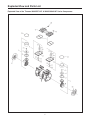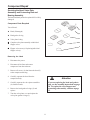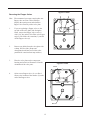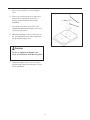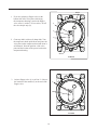
1
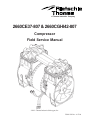
A Thomas Industries Company
2660CE37-807 & 2660CGHI42-807
Compressor
Field Service Manual
©2003 Thomas Industries Sheboygan, Inc.
FSM 0159 Rev. A 07/04
2
A Field Service Manual
Prepared by
A Thomas Industries Company
Thomas Compressor
2660CE37-807 & 2660CGHI42-807
Field Service Manual
©2003 Thomas Industries, Sheboygan Inc.
Field Service Manual FSM 0159
Rev. A 0704
Table of Contents
Page
Introduction ..................................................................................................................................................................... 4
Safety First ....................................................................................................................................................................... 5
Exploded View and Parts List ..................................................................................................................................... 6 - 7
Preventive Maintenance and Troubleshooting Guide ................................................................................................. 9 - 10
Required Tools and Materials ........................................................................................................................................ 11
Component Repair ......................................................................................................................................................... 11
Servicing the Head or Valve Assembly .................................................................................................................... 11
Servicing the Connecting Rod Assembly and Eccentric Assembly ....................................................................... 16
Reassembling the Compressor ................................................................................................................................ 20
3
Introduction
This Field Service Manual is intended for use ONLY by properly trained and experienced repair personnel employed by an
authorized service center. THIS SERVICE MANUAL SHOULD NOT BE USED BY OR DISTRIBUTED TO THE PUBLIC.
THE INSTRUCTIONS AND WARNINGS HEREIN PRESUME EXISTING FAMILIARITY WITH THE DESIGN AND
FUNCTION OF THESE AND SIMILAR PRODUCTS, AND THEIR COMPONENTS.
Please Note:
The model(s) represented in this manual may have additions and/or modifications made at any time. Pictures represent a standard
unit series and an actual unit may vary slightly. This manual is based on the latest technical information available at the time of
creation or last revision. It is believed to be generally accurate and reliable. Consult the factory if additional detailed information
is desired, or whenever there is a question about a given unit’s configuration or performance specifications.
4
Safety First
It is recommended that you thoroughly read and understand this manual before you attempt to service the
Thomas series of compressors to which this applies. PLEASE NOTE THE FOLLOWING CAUTIONS
AND WARNINGS FOR YOUR OWN SAFETY.
Caution
To avoid personal injury and/or property damage, only authorized service personnel should
service this unit.
Warning
To avoid the risk of electrical shock, personal injury, or death, disconnect power before servicing this
unit.
Caution
To avoid personal injury, do not remove fan guards while unit is connected to power.
Caution
To avoid personal injury, especially to eyes and face, use eye and face protection when
servicing this unit.
Caution
To avoid personal injury, especially to eyes and face, never point the exhaust air flow at
yourself or other people in the area. Unit is capable of pressures of 100 psig.
Caution
To avoid damage, never lubricate any component in your compressor. All moving parts are
permanently lubricated.
Caution
To avoid property damage or personal injury, always try rotating the fan by HAND prior to
connecting the unit to the power source. Check for suction at the air inlet port by placing your
finger over the port as you turn the fan. You should feel a slight suction with each rotation
of the fan. If you dont feel suction, or if you feel or hear a thump as you turn the fan, DO NOT
CONNECT THE UNIT TO A POWER SOURCE. Review the assembly procedure for
possible error.
5
Exploded View and Parts List
Exploded View of the Thomas 2660CE37-807 & 2660CGHI42-807 Series Compressor
6
Field Service Parts List for Thomas 2660CE37-807 & 2660CGHI42-807 Compressor
Item
No.
1
Part
No.
See Chart
Qty.
--
Qty.
Per Unit
2
Per Ass'y
Description
Connecting Rod, Eccentric & Bearing Assembly
2
624677
1
2
Piston Cup
3
625776
1
2
Screw - Piston Cup Retainer
4
626392
1
2
Piston Cup Retainer
5
618114
1
2
Cylinder Sleeve
6
610880
--
1
Head
7
623143
--
2
O-Ring - Head Gasket
8
625175
--
8
Screw - Head
9
621591
--
2
Valve Plate Assembly
10
617177
1
2
Valve Restraint
11
617562
2
4
Valve Keeper Strip
12
621485
2
4
Valve Flapper - Intake & Exhaust
13
621461
1
2
Valve Plate
14
625094
2
4
Screw - Valve Flapper
15
623137
--
2
O-Ring Valve Plate
16
638282
--
1
Fan - Black
17
638281
--
1
Fan - Gray
18
638702
--
1
Pressure Relief Valve
Connecting Rod, Eccentric & Bearing Assembly Chart
1
666660
--
2
For 2660CE37-807
1
666702
--
2
For 2660CGHI42-807
7
Preventive Maintenance and Troubleshooting Guide
Thomas Industries recommends that you perform the following service to minimize unexpected downtime
for your compressor:
•
Replace the connecting rods or piston cups and sleeves
•
Replace the flapper valves
•
Replace the head gasket O-rings
•
Replace the valve plate O-rings
8
Troubleshooting Guide
If you are having a problem with your compressor, use this table to help determine the cause(s):
Low
Flow
Problem
1
Low Unit Will Motor
Loud
Pressure Not Start Overheats Unit
x
Possible Cause
Corrective Action
x
High voltage at
compressor
Reduce voltage
x
Low voltage at
compressor
Increase voltage
x
x
x
x
x
Damaged valves
Replace flapper valves
x
x
x
Debris in valves
Remove debris and check
for valve damage
x
x
x
Damaged gaskets
Replace gaskets
x
x
x
Worn Cup
Replace connecting rod
assembly or cup
x
x
x
Loose head screws
Tighten head screws
Broken fan
Replace fan
Bent motor shaft
Replace entire unit
Damaged capacitor
Replace capacitor
Loose fittings
Tighten fittings
Insufficient
ventilation
in enclosure
Increase air
circulation
to enclosure
Worn bearings
Replace Conn Rod
Eccentric and
Bearing assembly
x
x
x
x
x
x
x
x
x
x
x
1 Thermal protector in motor will interrupt current when motor overheats.
9
Required Tools and Materials
To disassemble and reassemble your compressor, you need the following tools and materials:
Torque wrench that has an inch-pound scale (for head screws, set screws, flapper valve screw, and pipe plugs).
Torx® T-25 driver (for head screws).
1/8" Allen wrench attachment for torque wrench (for eccentric set screw).
1/2" Hex Socket attachment for torque wrench (for flapper valve screw).
Torx® T-27 driver (for retainer screws).
Soft, clean cloths
Compressor
Housing
Capacitor LEAD END
Capacitor LEAD SIDE
of Compressor
Reference Drawing: Terminology to assist with the following instructions.
10
Component Repair
Servicing the Head, Valve Plate
Assembly and Connecting Rod and
Bearing Assembly
The head would only need to be replaced if it is visibly
damaged.
Component Parts Required
You will need:
1
Head (if damaged)
2
Head gasket O-ring
3
Valve plate O-ring
4
Complete valve plate assembly or individual
flapper valves.
5
Flapper valve screw(s) if replacing individual
flapper valve(s).
Removing the Head
1. Disconnect the power.
2. Disconnect all air lines and remove
compressor from the enclosure.
3. Remove all screws (1) that fasten the head (2)
to the compressor housing.
4. Carefully separate the head from the
compressor body.
Attention
5. Carefully separate the valve plate assemblies
(4) from the heads.
If you are replacing the head and gaskets
only, see the assembly instructions on page
20. To replace the valve flappers and
connecting rod assembly, continue to page
12.
6. Remove the head gasket O-rings (3) and
replace.
7. Turn the valve plates over and replace the
valve plate gasket O-rings (5).
11
Opposite Lead Side
Removing the Flapper Valves
4
3
Note: We recommend you remove and replace one
flapper valve at a time. This will help to
simplify the repair process and orient the
flapper valve correctly on the valve plate.
2
1.
If you are replacing a flapper valve on the
top side of the valve plate (side facing the
head), remove the flapper valve screw (1)
with a 1/4" hex socket, lift off the valve keeper
strip (2), lift off the valve restraint (3), and lift
off the flapper valve (4).
2.
Remove any debris from the valve plate with
a damp, lint free cloth. (Soaps and
detergeants should not be used due to the
potential for corrosion from soap residue.)
3.
Place the valve plate on the compressor
housing and orient it as illustrated. Note the
orientation of the valve ports.
1
Opposite Lead Side
Port 1
2
4.
Orient a new flapper valve (1) over Port 1.
Observe the location of the notches (2) at the
end of the flapper valve.
1
2
2669-6
Port 2
12
5. Place a valve restraint (3) over the flapper
valve.
6. Place a valve keeper strip (4) over the valve
restraint observing that the word “UP” is
facing you and oriented as shown in the
illustration.
4
5
7. Line up the screw holes in all of the valve
components and insert the flapper valve screw
(5) into the valve plate.
3
8. Make sure the flapper valve is centered over
the port and that all of the other components
line up with the flapper valve.
Caution
Do not overtighten the flapper valve
screw or it will shear off in the valve plate.
9. Tighten the flapper valve screw to 18 inchpounds, using a torque wrench with a 1/4" hex
socket attachment.
13
Port 1
1. If you are replacing a flapper valve on the
bottom side of the valve plate (side facing
the compressor housing), remove the flapper
valve screw (1) with a 1/4" hex socket, lift off
the valve keeper strip (2),
1
2
3
2. Clean any debris with a soft, damp cloth. Turn
the compressor head upside down and place the
valve plate on the compressor head and orient it
as illustrated. Note the position of the valve
ports and the location of the power leads on the
compressor housing.
Port 2
Lead Side
3. Orient a flapper valve (1) over Port 2. Observe
the location of the notches (2) at the end of the
flapper valve.
2
1
Lead Side
14
3. Place a valve keeper strip (3) over the flapper
valve, observing that the word “UP” is facing
you, not the valve plate, and oriented as shown
in the illustration.
4. Line up the screw holes in all of the valve
components and insert the flapper valve screw
(4) into the valve plate.
4
5. Make sure the flapper valve is centered over
the Port and that the valve keeper strip lines up
with the flapper valve.
3
Caution
Do not overtighten the flapper valve
screw or it will shear off in the valve
plate.
6. Tighten the flapper valve screw to 18 inchpounds, using a torque wrench with a 1/4" hex
socket attachment.
Attention
If you are only replacing the valve
flappers, see the assembly
instructions on page 20.
If you are replacing the cup and
sleeve turn to the Rebuilding
Connecting Rod Assemblies Section
found on page 17.
15
Servicing the Connecting Rod Assembly
and Eccentric Assembly
Refer to the Preventive Maintenance and
Troubleshooting Guide in this manual to determine
whether a complete connecting rod assembly, or its
component parts, or an eccentric needs to be
serviced.
Component Parts Required
You will need:
Connecting rod assembly(ies) or piston cups and
sleeves
Valve plate gasket O-ring(s)
Head gasket O-ring(s) (if defective)
Removing the Connecting Rod Assembly
and Eccentric
NOTE: ONLY REMOVE ONE CONNECTING
ROD ASSEMBLY AT A TIME.
1. Carefully remove the fan by pulling it straight off
the motor shaft. Do not pull the fan blades.
16
2. Turn the motor shaft to align the eccentric set
screw with its access hole and use an Allen
wrench to loosen the eccentric set screw (see
illustration for location of access hole).
Eccentric
Eccentric Set Screw
Access Hole
Opening in
Housing
3. Make sure the connecting rod is at "Top Dead
Center". Slide the connecting rod assembly
straight off the shaft through the opening in the
housing.
17
Caution
Do not crimp the piston cup (4) when you
remove the connecting rod assembly from
the compressor housing. If the cup is
crimped, you must replace it.
Rebuilding Connecting Rod Assemblies
If you are rebuilding the connecting rod
assembly using component parts, follow this
procedure:
1
When replacing the piston cup (4), be sure
to replace the sleeve (1) at the same time.
Place the con rod shaft in a fixture before
attempting to remove the retainer screw.
Heat will help to dissolve the loctite bond.
2
3
4
1
5
1. Remove the retainer screw (2) from the
cup retainer.
2
3
2. Remove the retainer (3) from the
connecting rod.
4
3. Remove the cup (4) and discard.
5
4. Place the new piston cup (4) on the
connecting rod.
5. Place a piston cup retainer (3) on the
cup/connecting rod making sure the boss of
the retainer is seated in the pilot of the rod.
Note:
Both Connecting Rods
shown for
orientation,
DO NOT remove
both at once.
6. Insert the retainer screw (2) into the
connecting rod (5) and tighten to 95-105
inch-pounds.
Attention
To replace the connecting rod and
bearing assembly continue
to page 19.
18
Assembly of the Connecting Rod to the
Compressor
1. Line up eccentric set screw with flat on shaft.
Slide connecting rod assembly over shaft
through front of housing with eccentric toward
end of shaft. Push connecting rod assembly
tight against housing bearing.
Note: Both connecting rod assemblies shown
for orientation.
DO NOT remove both at once.
2. Rotate eccentric to line up set screw with
access hole in bottom of housing. Tighten
screw to 125 in. lbs. Make sure the eccentric
set screw is seated perpindicular on the shaft
flat.
Set Screw
Access Hole
19
Reassembling the Compressor
Top of Valve Plate
Groove
After the connecting rod assembly and eccentric
are correctly assembled, you can assemble the
valve plates and head to the compressor.
Caution
To prevent damage to the compressor,
never apply any sealant or lubrication to
the O-rings.
1. Insert a new head gasket O-ring into the
groove located on the top of the valve plate.
O-ring Gasket
O-ring Groove
2. Insert the valve plate gasket O-ring into the Oring groove located on the bottom of the valve
plate.
Bottom of Valve Plate
O-Ring
20
3. Position the compressor housing as shown in
the illustration. Notice the orientation of the
power leads.
Note: Make sure that the connecting rod
sleeves are seated against the compressor
housing.
Power
Leads
4. Observe the orientation of the valve plate
assemblies. The tabs on the valve plate
indicate exhaust side. Place them on the
compressor housing as shown.
Tab
Tab
Note: Ensure the valve plate is properly engaged
to housing locators.
Note: Ensure that O-Rings are fully assembled in
grooves and not pinched.
Valve Plate
Compressor
Housing
21
Power
Leads
Opposite Lead Side
5. Place the head on the valve plate assemblies
observing the position of the air intake and
exhaust ports.
4
6
Exhaust
2
8
Note: Make sure the head gasket O-rings are not
pinched.
6. Insert the head screws and finger tighten each
screw until it is snug.Use a Torx® T-25 driver
to tighten each head screw to 55 inchpounds, in the sequence shown.
5
Caution
3
7
1
Intake
Numbers indicate tightening sequence
To avoid property damage or personal
injury, always try rotating the fan by
HAND, prior to connecting the unit to
the power source. Check for suction at
the air inlet port by placing your finger
over the port as you turn the fan. You
should feel a slight suction with each
rotation of the fan. If you don't feel
suction, or if you feel or hear a thump
as you turn the fan, DO NOT
CONNECT THE UNIT TO A POWER
SOURCE; review the assembly
procedure for possible error.
Servicing the Fan
Clip Toward
Compressor
If one or both of the fans break, use the following
procedure:
1. Carefully remove the fan by pulling it straight
off the motor shaft.
2. Align the flat on the motor shaft with the flat
on the fan and slide the fan back onto the
motor shaft, making sure the fan clip (1) faces
as shown.
Clip Toward
Compressor
22
NOTES
23
A Thomas Industries Company
24