1
A4 Network Laser Printer
EPSON EPL-N1600
®
4009770
Notice
All rights reserved. No part of this manual may be reproduced, stored in a retrieval system, or transmitted in any form or by any means electronic,
mechanical, photocopying, or otherwise, without the prior written permission of SEIKO EPSON CORPORATION.
All effort have been made to ensure the accuracy of the contents of this manual. However, should any errors be detected, SEIKO EPSON would
greatly appreciate being informed of them.
The contents of this manual are subject to change without notice.
All effort have been made to ensure the accuracy of the contents of this manual. However, should any errors be detected, SEIKO EPSON would
greatly appreciate being informed of them.
The above not withstanding SEIKO EPSON CORPORATION can assume no responsibility for any errors in this manual or the consequences
thereof.
EPSON is a registered trademark of SEIKO EPSON CORPORATION.
General Notice:
Other product names used herein are for identification purpose only and may be trademarks or registered trademarks of their
respective owners. EPSON disclaims any and all rights in those marks.
Copyright © 1998 SEIKO EPSON CORPORATION. Printed in Japan.
PRECAUTIONS
Precautionary notations throughout the text are categorized relative to 1)Personal injury and 2) damage to equipment.
DANGER
Signals a precaution which, if ignored, could result in serious or fatal personal injury. Great caution should be exercised in
performing procedures preceded by DANGER Headings.
WARNING
Signals a precaution which, if ignored, could result in damage to equipment.
The precautionary measures itemized below should always be observed when performing repair/maintenance procedures.
DANGER
1. ALWAYS DISCONNECT THE PRODUCT FROM THE POWER SOURCE AND PERIPHERAL DEVICES PERFORMING ANY
MAINTENANCE OR REPAIR PROCEDURES.
2. NO WORK SHOULD BE PERFORMED ON THE UNIT BY PERSONS UNFAMILIAR WITH BASIC SAFETY MEASURES AS DICTATED
FOR ALL ELECTRONICS TECHNICIANS IN THEIR LINE OF WORK.
3. WHEN PERFORMING TESTING AS DICTATED WITHIN THIS MANUAL, DO NOT CONNECT THE UNIT TO A POWER SOURCE UNTIL
INSTRUCTED TO DO SO. WHEN THE POWER SUPPLY CABLE MUST BE CONNECTED, USE EXTREME CAUTION IN WORKING ON
POWER SUPPLY AND OTHER ELECTRONIC COMPONENTS.
WARNING
1. REPAIRS ON EPSON PRODUCT SHOULD BE PERFORMED ONLY BY AN EPSON CERTIFIED REPAIR TECHNICIAN.
2. MAKE CERTAIN THAT THE SOURCE VOLTAGES IS THE SAME AS THE RATED VOLTAGE, LISTED ON THE SERIAL NUMBER/
RATING PLATE. IF THE EPSON PRODUCT HAS A PRIMARY AC RATING DIFFERENT FROM AVAILABLE POWER SOURCE, DO NOT
CONNECT IT TO THE POWER SOURCE.
3. ALWAYS VERIFY THAT THE EPSON PRODUCT HAS BEEN DISCONNECTED FROM THE POWER SOURCE BEFORE REMOVING OR
REPLACING PRINTED CIRCUIT BOARDS AND/OR INDIVIDUAL CHIPS.
4. IN ORDER TO PROTECT SENSITIVE MICROPROCESSORS AND CIRCUITRY, USE STATIC DISCHARGE EQUIPMENT, SUCH AS
ANTI-STATIC WRIST STRAPS, WHEN ACCESSING INTERNAL COMPONENTS.
5. REPLACE MALFUNCTIONING COMPONENTS ONLY WITH THOSE COMPONENTS BY THE MANUFACTURE; INTRODUCTION OF
SECOND-SOURCE ICs OR OTHER NONAPPROVED COMPONENTS MAY DAMAGE THE PRODUCT AND VOID ANY APPLICABLE
1.
EPSON WARRANTY.
About This Manual
This manual describes basic functions, theory of electrical and mechanical operations, maintenance and repair procedures of EPL-N1600. The
instructions and procedures included herein are intended for the experienced repair technicians, and attention should be given to the precautions on
the preceding page.
Contents
Symbols Used in This Manual
This manual consists of six chapters and Appendix.
CHAPTER 1. PRODUCT DESCRIPTIONS
Provides a general overview and specifications of the
product.
CHAPTER 2. OPERATING PRINCIPLES
Describes the theory of electrical and mechanical
operations of the product.
CHAPTER 3. TROUBLESHOOTING
Provides the step-by-step procedures for
troubleshooting.
CHAPTER 4. DISASSEMBLY AND ASSEMBLY
Describes the step-by-step procedures for
disassembling and assembling the product.
CHAPTER 5. ADJUSTMENTS
Provides Epson-approved methods for adjustment.
CHAPTER 6. MAINTENANCE
Provides preventive maintenance procedures and the
lists of Epson-approved lubricants and adhesives
required for servicing the product.
APPENDIX Provides the following additional information for
reference:
• Connector pin assignments
• Electric circuit boards components layout
• Exploded diagram
• Electrical circuit boards schematics
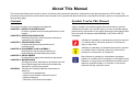
Various symbols are used throughout this manual either to provide
additional information on a specific topic or to warn of possible danger
present during a procedure or an action. Be aware of all symbols when
they are used, and always read WARNING, CAUTION or NOTE
messages.
W A R N IN G
C A U T IO N
C H E C K
P O IN T
Indicates an operating or maintenance procedure, practice
or condition that, if not strictly observed, could result in
injury or loss of life.
Indicates an operating or maintenance procedure, practice,
or condition that, if not strictly observed, could result in
damage to, or destruction of, equipment.
May indicate an operating or maintenance procedure,
practice or condition that is necessary to accomplish a task
efficiently. It may also provide additional information that is
related to a specific subject, or comment on the results
achieved through a previous action.
Safety Information
To prevent accidents during a maintenance procedure, strictly observe
the Warnings and Cautions. Do not do anything that is dangerous or not
within the scope of this document.
Do not do anything that is dangerous even if not specifically described
in this manual. In addition to the descriptions below and those given in
this manual, there are many situations and circumstances that are
dangerous. Be aware of these when you are working with the printer.
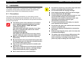
Safety Precautions
POWER SUPPLY AND ELECTRICAL COMPONENTS
Before starting any service procedure, turn off the printer and unplug
the power cord from the wall outlet. If you must service the printer when
the power is applied, be aware of the potential for electrical shock and
do all tasks by following the procedures in this manual.
W A R N IN G
Do not touch electrical components on the HPS unless
you are instructed to do so by a service procedure.
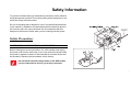
MECHANICAL COMPONENTS
Safety Components
If you service a driving assembly (e.g., gears), first turn off the power
and unplug the power cord. Then manually rotate the assembly.
The printer is equipped with safety components (e.g., interlock
switches, fuses, thermostat) and safety switches for protecting users
and service personnel from injury and the equipment from damage.
W A R N IN G
Do not touch the driving part (e.g., gears) while the
assembly (printer) is being driven.
Interlock Switch
The interlock switch opens to interrupt +24VDC and +5V-LD (Laser
diode drive) from the power supply circuit (HPS) to the controller
circuit (C258MAIN) when the Cover Assy. Exit is open.
Warning/Caution Labels
WARNING and CAUTION labels are stuck on dangerous parts in the
printer to make you aware of the potential dangers that are present
when you are working with those parts.
ROS ASSY.
The laser beam used in this printer is invisible and it has a narrower
frequency band and more coherent phases than any other light
(sunlight, electric light). It has excellent monochromaticity and
convergence. A thin laser beam reaches long distances. Because of its
convergence characteristic, the laser beam converges into one point,
causing high density and high temperature. A laser beam is harmful to
the human body.
W A R N IN G
Do not expose yourself to the laser beam to prevent
injury (blindness).
Do not open the cover that has the laser beam
warning label.
If you disassemble or assemble the printer, turn off
the power.
If you need to work on the printer with power applied,
strictly follow the instructions in this manual.
Understand how the laser beam functions and take
maximum precautions not to injure yourself or anyone
around you.
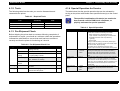
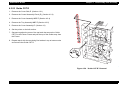
FUSER ASSY.
To prevent you from becoming injured or burned, do the following
before working with a high temperature Assembly (e.g., Fuser
Assembly):
turn off the printer.
Unplug the power cord.
Wait until it cools down.
W A R N IN G
The high temperature Assembly is very hot
immediately after any printer operations. Wait at least
40 minutes before you start working on the printer.
General Cautions
Some materials (e.g., Developer or Fuser Oil) may cause bodily
injury. Do not swallow or inhale these materials or allow them to
come in contact with the eyes.
Help to protect those around you and follow the prohibitions against
swallowing or inhaling those materials. Be careful to protect the
eyes at all times.
Place a sheet under the printer so that the floor or workbench is
protected.
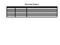
Revision Status
Revision
Issued Date
Description
Rev. 0
August 17, 1998
Preliminary release. (intended for service training purpose only)
Rev. A
October 30, 1998
First issue.
E P S O N E P L -N1 6 0 0
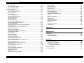
Table of Contents
Product Description
Operating Principles
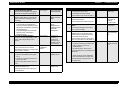
OVERVIEW .................................................................................................. 14
CONSUMABLES AND OPTIONS ........................................................... 14
OVERVIEW .................................................................................................. 38
Electrophotographic Printing ................................................................... 38
Paper Transportation .............................................................................. 40
Main Engine Components Function ........................................................ 41
Main Control Circuit................................................................................. 55
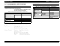
SPECIFICATIONS........................................................................................ 15
ENGINE SPECIFICATIONS.................................................................... 15
PAPER SPECIFICATIONS ..................................................................... 16
CONTROLLER SPECIFICATIONS......................................................... 17
ELECTRICAL SPECIFICATIONS ........................................................... 18
CONSUMABLES..................................................................................... 18
OTHER SPECIFICATIONS..................................................................... 18
ENVIRONMENTAL SPECIFICATIONS .................................................. 19
OPERATING CONDITIONS.................................................................... 20
SAFETY APPROVAL .............................................................................. 21
RELIABILITY, DURABILITY AND MAINTENABILITY............................. 22
EXTERNAL DIMENSIONS AND WEIGHT.............................................. 23
INTERFACE SPECIFICATIONS .................................................................. 24
Bidirectional Parallel Interface................................................................. 24
Serial Interface ........................................................................................ 25
OPERATING SPECIFICATIONS ................................................................. 26
Panel Settings ......................................................................................... 28
OneTouch Mode ................................................................................ 28
SelecType Mode ................................................................................ 28
Printer Status Messages ......................................................................... 31
Initialization Process................................................................................ 32
Special Functions .................................................................................... 33
OTHER SPECIFICATIONS..................................................................... 34
Jumper Settings ................................................................................. 34
Program-ROM Specifications............................................................. 34
RAM Capacity .................................................................................... 35
Operating Precaution ......................................................................... 35
Rev. A
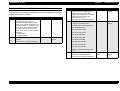
Troubleshooting
OVERVIEW ..................................................................................................
Service-Call Errors ..................................................................................
Printer Messages ....................................................................................
Status Messages ...............................................................................
Error Messages..................................................................................
Warning Messages ............................................................................
58
58
60
61
62
66
Troubleshooting............................................................................................
Troubleshooting with Error Messages.....................................................
Troubleshooting with Printer Operation...................................................
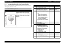
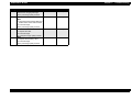
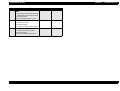
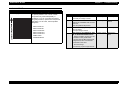
Troubleshooting with Print Image Quality ...............................................
67
67
76
82
Disassembly and Assembly
OVERVIEW ................................................................................................
Precautions ...........................................................................................
Tools .....................................................................................................
Pre-Shipment Check .............................................................................
Special Operaiton for Service ...............................................................
100
100
101
101
101
DISASSEMBLY AND ASSEMBLY ............................................................. 103
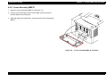
Cover Side,E ......................................................................................... 104
Shield Assembly Top.ST ....................................................................... 105
11
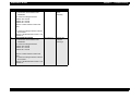
E P S O N E P L -N1 6 0 0
Control Panel......................................................................................... 106
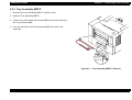
Cover Assembly MBF.E ........................................................................ 107
Tray Assembly MBF.E........................................................................... 108
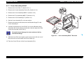
Cover Assembly,E ...................................................................................... 109
Cover Assembly Exit,E.......................................................................... 110
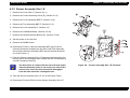
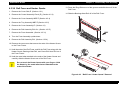
Sensor Assembly-Size 1,E.................................................................... 111
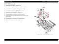
Drive Assembly ..................................................................................... 112
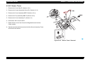
Solenoid Feed ....................................................................................... 113
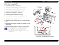
Chute Inlet Registration......................................................................... 114
Roll Assembly Registration ................................................................... 115
Roll Assembly Feed .............................................................................. 116
Actuator No Paper................................................................................. 117
Roll Assembly Turn ............................................................................... 118
Actuators Pre-Registration A and B ...................................................... 119
Kit Chute Registration Assembly........................................................... 120
Actuator Registration............................................................................. 121
Link Interlock Switch and Cam Interlock Switch.................................... 122
Chute Exchange.................................................................................... 123
Actuator Exit-2/L, -2/S and Sensor Photo ............................................. 124
Solenoid Exchange ............................................................................... 125
Gear Duplex Assembly.......................................................................... 126
Roll Assembly Pinch Pre-Registration................................................... 127
Frame Assembly MBF........................................................................... 128
Solenoid MBF........................................................................................ 129
Roll Assembly MBF ............................................................................... 130
Holder Gear MBF .................................................................................. 131
Gear Assembly MBF ............................................................................. 132
Plate Assembly Bottom MBF................................................................. 133
Sensor No Paper MBF .......................................................................... 134
Pad Assembly Retard and Stopper Paper ............................................ 135
Roll Assembly Exit Out.......................................................................... 136
Roll-Press and Bearing-Pressure Roll................................................... 137
Actuator-Exit.......................................................................................... 138
Sensor Assembly Photo Exit ................................................................. 139
Fuser Assembly..................................................................................... 140
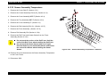
Sensor Assembly Temperature............................................................. 141
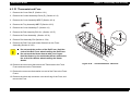
Thermostat and Fuse ............................................................................ 142
Roll Assembly Exit................................................................................. 143
Roll-Pinch .............................................................................................. 144
Roll Fuser and Heater Quartz ............................................................... 145
Rev. A
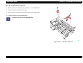
ROS Assembly ...................................................................................... 146
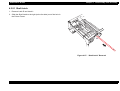
Mirror Assembly .................................................................................... 147
Roll Assembly BTR ............................................................................... 148
Sensor Toner ........................................................................................ 149
Switch Assembly 5V Interlock ............................................................... 150
Drive Assembly-F/P .............................................................................. 151
Drive Assembly Main ............................................................................ 152
Shield Assembly Bottom (E) ................................................................. 153
Fan IOT ................................................................................................. 154
Chassis Assembly PS ........................................................................... 155
HPS ...................................................................................................... 156
PWBA Hotaru ........................................................................................ 157
C258MAIN Removal ............................................................................. 158
Latch R and Latch L .............................................................................. 159
Shaft Latch ............................................................................................ 160
Guide R (A) and (B) .............................................................................. 161
Guide CST R ......................................................................................... 162
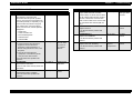
Adjustment
Maintenance
OVERVIEW ................................................................................................ 166
User Maintenance ................................................................................. 166
Service Maintenance............................................................................. 166
Appendix
Electrical Connection..................................................................................
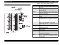
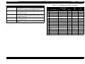
Connectors - C258MAIN .......................................................................
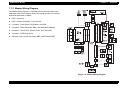
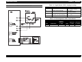
Master Wiring Diagram .........................................................................
Wiring Diagram Notation ..................................................................
168
168
169
170
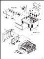
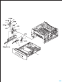
Exploded Diagram...................................................................................... 181
Circuit Schematics...................................................................................... 208
12
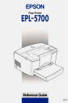
PRODUCT DESCRIPTION
EPSON EPL-N1600
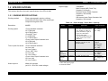
1.1 OVERVIEW
The EPL-N1600 is the latest in EPSON’s advanced lines of laser
printers and offering the following features.
Chapter 1
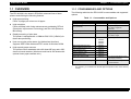
1.1.1 CONSUMABLES AND OPTIONS
The following table lists the EPL-N1600’s consumables and supported
options.
Table 1-1. Consumables and Options
High-speed printing
Prints 16 pages per minute on A4 paper.
High resolution
Prints at 600dpi, with further enhancement provided by RITech
(Resolution Improvement Technology) and Enh. MG (Enhance
MicroGray).
Rapid processing of print data
The printer is equipped with a 150MHz RISC-CPU (VR4310) for
faster data processing.
Item
Note
S051056
Life: 8500 pages
500 Sheet Lower Paper Cassette
Unit (Universal)
C81290*
Supported paper size:
A4, Letter, Legal, B5,
Executive
Face Up Tray
C81294*
Eject capacity: 40 sheets
Duplex Unit
C81293*
Supported paper size:
A4, Letter, Legal
Ethernet Card
C82357*
C82362*
C82363*
C82364*
Type-B Optional I/F Card
32KB Serial Interface Card
C82307*
32KB Parallel Interface Card
C82310*
Coax Interface Card
C82314*
Twinax Interface Card
C82315*
GPIB Interface Card
C82313*
AppleTalk Interface Card
C82312*
Use with EPSONScript Level
2 package (C83229*)
EPSONScript Level 2 Package
C83229*
• Emulates PostScript Level2
• ROM module
*:
Rev. A
Code
Imaging Cartridge
Host can monitor printer status (by bidirectional interface)
Supports IEEE-1284 nibble and ECP modes in Windows 95/98.
High-capacity paper sources
The printer comes standards with a 80-sheet MP tray and a 250sheet universal cassette. (Maximum total load is 830 sheets with
optional lower paper cassette unit.)
Product Description
The asterisk (*) is a substitute for the last digit of the product code, which varies by
country.
14
EPSON EPL-N1600
Chapter 1
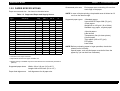
1.2 SPECIFICATIONS
Paper Supply:
This section describes the basic specifications of the EPL-N1600.
1.2.1 ENGINE SPECIFICATIONS
Printing method:
Electro-photographic printing, utilizing
semiconductor laser beam scan and singlecomponent magnetic toner
Resolution:
600DPI
Printing speed:
<From Standard cassette>
15.7 PPM (A4)
16.6 PPM (Letter)
<From MP Tray>
11.3 PPM (A4)
11.7 PPM (Letter)
<From Lower Paper Cassette Unit>
15.2 PPM (A4)
16.0 PPM (Letter)
Time to print first sheet:
<From standard cassette>
14.4 sec (A4)
14.2 sec (Letter)
<From <MP Tray>
13.3 sec (A4)
13.1 sec (Letter)
<From Lower Paper Cassette Unit>
15.5 sec (A4)
15.3 sec (Letter)
Product Description
<Standard>
Multi Purpose (MP) Feed Tray
(Capacity: 80 sheets)
Universal Lower Paper Cassette
(Capacity: 250 sheets)
<Optional>
500-sheets Lower Paper Cassette Unit
(Capacity: 500 sheets)
Table 1-2. Paper Supply / Paper Size / Capacity
Paper
Supply
MP Tray
Capacity
Paper Size
Paper Thickness
80 sheets
*1
• Standard size paper
90 x 148 - 215.9 x 355.6mm
(A4, JIS-B5, A5, Letter, GLetter, Executive, Legal, GLegal, F4, Half-Letter)
• Custom size paper
Any size of paper within the
range of 90 x 148 - 215.9 x
355.6mm
Normal paper:
60 - 105g/m²
(16 - 28lb)
10 sheets
Envelopes
(Monarch, C10, DL, C5, C6,
International-B5)
Special paper:
190g/m²
Normal paper:
60 - 105g/m²
(16 - 28lb)
40 sheets
Labels / OHP sheet
Special paper
Standard
Paper
Cassette *2
250 sheets
*1
A4, Letter, G-Legal, Legal, JIS-B5
Normal paper:
60 - 105g/m²
(16 - 28lb)
Lower Paper
Cassette
Unit *2
500 sheets
*1
A4, Letter, G-Legal, Legal
Normal paper:
60 - 105g/m² (16 28lb)
*1: With 20lb (70g/m²) paper.
Warm-up time:
Rev. A
Within 45 seconds
(at 22°C / 55% RH / rated voltage)
*2: Universal cassette.
15
EPSON EPL-N1600
Chapter 1
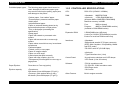
1.2.2 PAPER SPECIFICATIONS
Guaranteed print area:
Product Description
Entire paper area, excluding 4.0 mm from
each edge of the paper.
Paper sources and size : As shown in the table below.
NOTE: In case of duplex printing, the printable area is limited to 6.0
mm from the bottom edge.
Table 1-3. Supported Paper and Supply Source
Size
mm (inch)
Type
MP
Tray
STD
CST *1
Lower
CST *2
Duplex
*3
A4
210 x 297
Yes
Yes
Yes
Yes
A5
148 x 210
Yes
No
No
No
JIS-B5
182 x 257
Yes
Yes
No
No
LT
215.9 x 279.4 (8.5 x 11")
Yes
Yes
Yes
Yes
HLT
139.7 x 215.9 (5.5 x 8.5")
Yes
No
No
No
LGL
215.9 x 355.6 (8.5 x 14")
Yes
Yes
Yes
Yes
EXE
184.15 x 266.7 (7.25 x 10.5")
Yes
Yes
No
No
GLG
215.9 x 330.2 (8.5 x 13")
Yes
Yes
Yes
Yes
GLT
203.2 x 266.7 (8 x 10.5")
Yes
No
No
No
F4
210 x 360
Yes
No
No
No
MON
98.43 x 190.5 (37/8 x 7½")
Yes
No
No
No
C10
104.78 x 241.3 (41/8 x 9½")
Yes
No
No
No
DL
110 x 220
Yes
No
No
No
C5
162 x 229
Yes
No
No
No
C6
114 x 162
Yes
No
No
No
I-B5
176 x 250
Yes
No
No
No
16MO
198 x 275
Yes
No
No
No
Supported paper types:
<Standard paper>
Xerox 4024 DP Paper 20lb (75 g/m²)
<Plain paper>
Weight=60 to 150 g/m² (16 to 28 lbs)
Standard copy paper, recycled paper
<Special paper>
Label sheets
Transparency film (for laser printer)
Colored paper
Thick paper (105 to 157 g/m²)
DTP paper
Letter head
NOTE: Before purchasing paper in large quantities, check that
sheets are fed correctly.
Special paper, such as thick paper must be fed from the
paper tray (do not feed from cassettes).
*1: Universal Lower Paper Cassette
*2: Optional 500-sheets lower paper cassette unit
*3: Duplex printing is available only with a sheet fed from the cassette unit (standard or
optional).
Supported paper sizes:
Width= 90 to 216 mm (3.5 to 8.5 ")
Length=148 to 355.6mm (5.8 to 14 ")
Paper feed alignmnent:
Left alignmnent for all paper size
Rev. A
16
EPSON EPL-N1600
Prohibited paper types:
Chapter 1
The following paper types should never be
used. Attempts to feed these paper types
may result in inferior print quality, paper jams,
and damage to the printer.
*Carbon paper, "non-carbon" paper
*Thermal paper, pressure-sensitive paper
*Acidic paper
*Inkjet-dedicated paper
*Paper or postcard already printed on by
thermal-transfer printer or inkjet printer
*Thin or thick paper (exceeding the
specification)
*Damp paper
*Paper with coated or processed color
surface
*Paper with extra smooth or extra rough
surface
*Paper whose rear side has very inconsistent
smoothness
*Perforated paper
*Folded, curled, or torn paper
*Paper of irregular shape
*Paper cut at off-angle
*Label sheets that peel too easily
*Paper with clips, staples, glue, etc.
*Transparency film designed for color copy or
page printer
Paper Ejection:
Face-down or Face-up (option)
Ejection capacity:
<Face-down>
250 sheets (Xerox 4024 paper (75 g/m²))
<Face-up> (with optional face-up tray)
40 sheets (Xerox 4024 paper (75 g/m²))
Rev. A
Product Description
1.2.3 CONTROLLER SPECIFICATIONS
CPU:
RISC-CPU (VR4300 / 150MHz)
RAM:
<Standard> 8MB EDO RAM
<Optional>
1 EDO-RAM SIMM slot
(Accepts 4MB to 32MB EDO-RAM SIMM)
Maximum memory is 40MB
ROM:
Font:
2MB (on-board)
4MB
(on ROM-DIMM module)
Program:
(Installed in ROM-DIMM socket)
Expansion ROM:
2 ROM-DIMM slots (A/B slots)
A slot=For C83229* (EPSONScript) module
B slot=For local-font ROM module only
Interfaces:
<Standard>
*Bidirectional parallel I/F (B type connector)
(IEEE-1284 compliant / Compatibility, Nibble
and ECP mode)
*RS-232C serial I/F (D-SUB 25pin)
<Optional>
*Type-B interface slot (1 slot)
Control Panel:
*8 push-button switches and 6 LED lamps.
*LCD Panel (1-line 20-column)
Software:
*PCL5e emulation mode
*FX, ESC/P2, I239X emulation mode
*ESC/Page mode
*GL/2 mode
Other Feature:
Built-in engine controller
17
EPSON EPL-N1600
Chapter 1
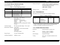
1.2.4 ELECTRICAL SPECIFICATIONS
Power Requirements:
Dielectric Strength:
Insulation shall not break down when the
following voltage is applied between primary
circuit and chassis for 1 minute:
*100V model: AC1000V
*200V model: AC1500V
Leakage Current:
3.5mA or less
See table below.
Table 1-4. Power Supply Specification
Item
100V Model
200V Model
Input Voltage
120V ±10%
(90 to 132V)
220 - 240V ±10%
(198 to 264V)
50 - 60Hz ±3Hz
50 - 60Hz ±3Hz
6.5A
3.5A
Rated Frequency
Rated Current
Power Consumption
•
•
•
•
Maximum:
Continuous printing:
Stand-by (Heater ON):
Stand-by (Heater OFF):
AC Line Noise:
700W
350W
70W
30W
Pulse width= 50 to 1000 ns
Pulse polarity=+ / Repetition= Asynchronous
Modes=
Common / Normal
1KV
Voltage=
(Parts must be able to withstand 2KV without
damage)
Transient Outage:
DIP 100% (at rated voltage - 10%) 1 cycle
Electrostatic Tolerance:
<upto 10KV>
No hard error, no user-nonrecoverable
software error
<upto 15KV>
No damage to parts
Surge Current:
1/2-cycle / Not above 50A
Insulation Resistance:
10Mohm or more
Rev. A
Product Description
1.2.5 CONSUMABLES
This printer's only consumable part is the Imaging Cartridge.
Table 1-5. Imaging Cartridge
Name
Imaging Cartridge
S051056
Components
•
•
•
•
•
•
Development unit
Toner
OPC Drum
Charging Roller
Waste Toner Box
Cleaner Blade
Life
Average:
8500 pages *
Weight
Approx. 1.3Kg
*: Toner life is estimated based on continuous printing on A4 size paper with 5% print
coverage. Toner life will vary according to print coverage and printing method
(continuous or intermittent, print density, toner-save mode, etc.).
1.2.6 OTHER SPECIFICATIONS
Printer life:
300,000 sheets or 5 years in use
Noise:
Stand-by: Approx. 32.0dB(A)
Operating: Approx. 50.0dB(A)
Ozone Density:
Less than 0.02 ppm
Toxicity:
OPC, toner, and plastic materials are all
nontoxic.
18
EPSON EPL-N1600
Chapter 1
1.2.7 ENVIRONMENTAL SPECIFICATIONS
CONSUMABLES
Table 1-7. Environmental Conditions - Consumables
MAIN UNIT AND CONSUMABLES
Temperature and humidity: See table below.
(The conditions below are applicable for both
the main unit and consumables.)
Table 1-6. Environmental Conditions - Main Unit
Humidity Temperature
Item
Conditions
Normal
0 to 35°C
High temperature
35 to 40°C
Low temperature
-20 to 0°C
Normal
Extreme
(within 1 month)
Normal
Extreme
(within 1 month)
0 to 35°C
High temperature
35 to 40°C
Low temperature
-20 to 0°C
Normal
Extreme
(within 1 month)
Conditions
20 to 80%RH
High humidity
80 to 95%RH
Low humidity
10 to 20%RH
Air Pressure
460 to 760hPa
Storage
Within 24 months from the
production
20 to 80%RH
High humidity
80 to 95%RH
Low humidity
10 to 20%RH
Within 24 months from the
production
Storage
Air Pressure (Altitude):
460 to 760hPa (Max. 2500 meters)
Drop Tolerance:
No damage when tested in accordance with
JIS Z0200-1987 level 1
Direction=1 corner, 6 sides, 3 edge
Vibration Tolerance:
Vibration=
Acceleration=
Sweep time=
Direction=
Time=
Rev. A
Humidity Temperature
Item
Extreme
(within 1 month)
Product Description
5 to 100Hz / 100 to 5Hz
0.7G
10 minutes (one way)
Three directions (X/Y/Z)
50 minutes in each direction
19
EPSON EPL-N1600
Chapter 1
Product Description
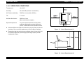
1.2.8 OPERATING CONDITIONS
Temperature:
10 to 32°C
Humidity:
20 to 80%RH (without condensation)
Air Pressure (Altitude):
760hPa or more (below 2500m)
Tilt:
5° or less
Ambient Illumination:
3000 lux or less
(Must avoid direct sunlight.)
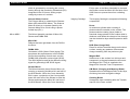
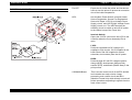
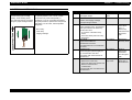
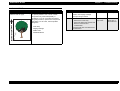
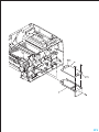
Space Requirement:
To ensure proper operation of the printer,
sufficient open space must be left around
printer, as indicated in the illustration below.
At least 400mm free space must be left at top of printer to allow for
opening of the cover and replacement of the Imaging Cartridge.
Figure 1-1. Space Requirement (1)
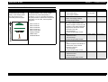
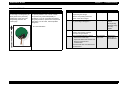
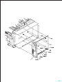
Remember that the printer becomes higher when a lower feed unit
is installed. Maximum printer height (with large-capacity feeder
installed) is 453mm.
Figure 1-2. Space Requirement (2)
Rev. A
20
EPSON EPL-N1600
Chapter 1
1.2.9 SAFETY APPROVAL
Others:
Safety Regulation
Model
Applicable Standard
100V Model
• UL 1950
• CSA 22.2 No.950
200V Model
• TUV-GS (EN60950)
Safety Regulation (Laser Radiation)
Model
Applicable Standard
100V Model
FDA (NCDRH) Class 1
200V Model
TUV-GS (EN60825)
Product Description
<Toner>
No effect on human health.
(In compliance with OSHA, TSCA, EINECS,
woker safety laws and CSCL)
<OPC>
No effect on human health.
(In compliance with OSHA)
<Ozone>
In compliance with UL478 5th Edition
<Materials>
In compliance with Swiss environment
protection law (no CdS content)
EMC
Model
Applicable Standard
100V Model
• CNS 13438
• CISPR22 (for Taiwan)
• FCC Part15 Subpart B Class B / CSA C108.8 Class B
200V Model
• EC EMC directive 89/336/PEC
EN55022 Class B
EN61000-3-2
EN61000-3-3
EN50082-1
• AS 3548 (for Australia)
Power consumption:
Rev. A
In compliance with International Energy Star
program
21
EPSON EPL-N1600
Chapter 1
1.2.10 RELIABILITY, DURABILITY AND
MAINTENABILITY
MPBF:
Life:
MTTR:
Jam Rate:
120,000 sheets
(Average number of sheets printed between
failures, where "failure" indicates a condition
that requires part replacement or that cannot
be corrected by user.)
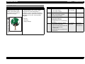
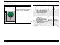
Print Start Position:
Using standard paper from paper tray or
cassette;
<Main scan direction>
Target position (c) ±2.5mm
<Subscan direction>
Target position (a) ±2.0mm
Skew:
Using standard A4 paper from paper tray or
cassette;
300,000 sheets or 5 years in use
(whichever comes first)
30 minutes
(Average time to complete and confirm repair
after ascertaining the site of the failure.)
Product Description
<Main scan direction>|c - d | ±2.0mm
<Sub scan direciton> | a - b | ±1.5mm
Ejection Curl:
20mm or less
(after 5 minutes from ejection)
As indicated in the table below.
Table 1-8. Paper Feed Reliability
Cassette
MP Tray
Single-side
Print
Duplex Print
Single-side
Print
Special Paper
Jam Rate
1/3000 or less
1/2000
1/600
1/100
Mis-feed rate
1/800 or less
-
1/300
1/25
*: Above figures are based on uncurled paper used immediately after removal from
package.
*: The above figures include jams caused by misfeeds, multiple feeds, etc.
*: The above figures do no cover feeding at interface between paper stacks loaded at
different times.
Figure 1-3. Printing Accuracy
Rev. A
22
EPSON EPL-N1600
Chapter 1
Product Description
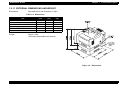
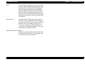
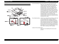
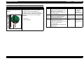
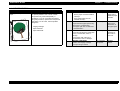
1.2.11 EXTERNAL DIMENSIONS AND WEIGHT
Dimensions:
See table below and illustration on right.
Table 1-9. Dimensions
Width
(mm)
Item
Depth
(mm)
Height
(mm)
EPL-N1600(Main unit)
421
420
264
Lower Paper Cassette Unit (C812902)
396
389
114
(With main unit)
421
420
379
Duplex Unit (C812932)
396
517
254
(With main unit)
421
542
325
Full option
421
542
441
Weight:
Approx. 13Kg
(excluding consumables and options)
Figure 1-4. Dimensions
Rev. A
23
EPSON EPL-N1600
Chapter 1
Product Description
1.3 INTERFACE SPECIFICATIONS
The EPL-N1600 supports the following interfaces.
Table 1-10. Bidirectional Parallel I/F Pin Assignment
Pin
Bidirectional parallel I/F (standard)
RS-232C serial (standard)
Type-B interface slot (1 slot for optional interface card)
I/O
IEEE 1284-B Connector
*1
Compatibility
1
In
nStrobe
2-9
In/Out
Nibble
ECP
HostClk
DATA1 - 8
10
Out
nACK
PtrClk
PeriphClk
11
Out
Busy
PrtBusy
PeriphAck
AckDataReq
12
Out
PError
13
Out
Select
The printer's built-in parallel interface complies with IEEE-1284, and
supports Compatibility, Nibble and ECP modes.
14
In
nAutoFd
15
-
NC
16
-
GND
Transmission:
8-bit parallel (IEEE-1284 compliant)
17
-
CG
18
Out
PeripheralLogic High
Synchronization:
By externally supplied STROBE signal
(STRBX)
19-30
-
GND
1.3.1 Bidirectional Parallel Interface
Handshaking:
Logic Level:
Connector:
By ACKX or BUSY
TTL level
IEEE-1284-B connector (36pin)
(57RE-40360-830B(D7A) DDK or equivalent)
Mode:
Compatibility, Nibble and ECP mode
Pin Assignment::
See the table on right.
Rev. A
31
In
32
Out
nFault
33
-
GND
34
-
NC
35
Out
+5V
36
In
nSelectin
nAckReverse
Xflag
HostBusy
nInit
HostAck
nReverseRequest
nDataAvail
nPeriphRequest
IEEE1284 Active
*1: "I/O" indicates a signal direction viewed from the printer.
24
EPSON EPL-N1600
Chapter 1
Product Description
1.3.2 Serial Interface
Type:
RS-232C (conforms to EIA)
Transmission:
Full duplex
Synchronization:
Table 1-11. Serial I/F (RS-232C) Pin Assignment
Pin
Signal
I/O
*1
2
TXD
Out
3
RXD
In
Received data. This pin transmits data from the
computer to the printer.
5
CTS
In
Always ignored.
Asynchronous
Description
Transmits data. This pin transmits serial data from
the printer to the computer.
Transmission rates:
300 to 57600 bps
Parity bit:
Even, Odd or NONE
17
Start bit:
1
20
Stop bit:
1/2
Data length:
7 or 8 bits
Protocols:
•XON/XOFF control (software control)
(Robust mode is supported)
•DTR control (hardware control)
23
Connector:
D-SUB 25pin
(17LE-13250-27(D57)
Received data. This pin transmits data from the
computer to the printer.
24
Transmits data. This pin transmits serial data from
the printer to the computer.
See the table on right.
25
Pin Assignment:
DTR
Out
Transmits data. This pin transmits serial data from
the printer to the computer.
Out
Data terminal ready. This pin indicates whether or
not the printer is ready to receive data. If the
printer ready protocol is not selected, the printer is
always ready to receive data (this pin is always
HIGH). If the printer ready protocol is selected, the
printer can accept data when the pin level is HIGH
and cannot accept data when the pin level is
LOW. When the DTR signal goes LOW, the host
computer must stop sedning data within 256
characters. This function can be set on or off with
the default-setting mode of the printer.
In
Received data. This pin transmits data from the
computer to the printer.
*1: "I/O" indicates a signal direction viewed from the printer.
Rev. A
25
EPSON EPL-N1600
Chapter 1
Product Description
1.4 OPERATING SPECIFICATIONS
LCD PANEL
The control panel of the EPL-N1600 includes a variety of buttons and
indicator lamps, together with an LCD. The user can use the panel to
select the printer's operating mode, to set the various printer functions,
and to view settings and status information.
1-line by 20 column LCD display equipped with backlight, and it is used
for displaying printer status and setup menus
LED LAMPS
There are 6 LED lamps and a function of each one of these LED lamps
are as below.
Figure 1-5. EPL-N1600 - Control Panel
Rev. A
On Line LED
ON:
Printer is ready to receive data and print.
OFF: Printer is not for receiving print data.
Form Feed LED
ON:
Printer contains data that has not yet been processed.
(If data is not effective print data, light will not be on.)
OFF:
Printer has finished processing all print data.
(If control code is not terminated, however, this lamp will
be ON.)
Brinking: Printer is currently processing data.
Continue LED
Brinking: Printer is in error state. User can clear the error by
pressing the Clear Error button.
One-Touch Mode 1 / 2 LED
Indicate that panel is either in One-Touch mode 1.or One-Touch
mode 2.
SelecType
Indicates that printer is in SelecType setting mode.
26
EPSON EPL-N1600
BUTTONS
OnLine button
Toggles printer ONLINE state on and off. (If printer is in one of the
setup modes, this switch releases the mode and sets the printer to
ONLINE state.)
Form Feed button
If the printer contains data but is not enabled for printing (if Form
Feed lamp is on), this switch causes printer to output printing results
and eject the paper. (This button does not cause ejection if Form
Feed lamp is off.)
Chapter 1
Continue button
Clears error (if pressed while Continue LED is blinking). When
printer is in ONLINE state, this button will also clear any warning
display that may appear on the LCD.
SelecType / ALT button
Selects the panel setting mode: OneTouch Mode 1, OneTouch
Mode 2, or SelecType Mode. Also operates as a ALT key. Panel
button operations vary according to the currently selected panel
setting mode.
Product Description
ITEM button
Selects the corresponding OneTouch mode option listed above this
button, or selects the fucntion available within the current menu,
after entering the SelecType mode.
VALUE button
Selects the corresponding OneTouch mode option listed above this
button, or selects the parameter available within the current item,
after entering the Item of the SelecType mode.
ENTER button / Status Sheet print
Selects the corresponding OneTouch mode option listed above this
button, or accepts the setting curretnly shown on the LCD as a new
setting when in SelecType mode.
Press this button twice when the printer is online to print the status
sheet.
RESET (ALT + Conitnue)
Pressing the Continue button while holding down the ALT button will
reset the printer. The LCD will display the message RESET. To
generate a complete reset (warm boot), continue to hold down these
buttons for approximately five seconds after the RESET message
appears; the message will then change to RESET ALL and the
printer will start warm-up processing.
MENU button
Selects the corresponding OneTouch mode setting listed above this
button, or selects the SelecType menu if in SelecType mode. Press
this button whe the printer is online to enter SelecType mode.
Rev. A
27
EPSON EPL-N1600
Chapter 1
Product Description
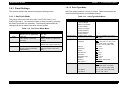
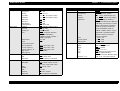
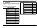
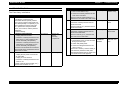
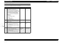
1.4.1 Panel Settings
1.4.1.2 SelecType Mode
This section explains the printer's three panel-setting modes.
SeleType mode presents a variety of menus. Table below shows the
mode's switch operations and available settings.
1.4.1.1 OneTouch Mode
Table 1-13. SelecType Mode Menu
The printer offers two quick-set modes: OneTouch mode 1 and
OneTouch mode 2. You can select either of these modes by pressing
the SelecType button as necessary. The following table shows the
settings that can be made from each of these modes.
MENU Button
OneTouch Mode 1
Status Sheet
LJ4 Font Sample
ESCP2 Font Sample
FX Font Sample
I239X Font Sample
PS Status Sheet*1
PS Font Sample*1
PS Fact Sheet*1
Emulation Menu
Parallel / Serial / AUX*2
Auto / LJ4 / ESCP2 / FX / I239X /
PS*1 / GL2
Printing Menu
Paper Source
Page Size
Auto / MP / LC1 / LC2*3
A4 *4 / A5 / / B5 / LT / HLT / LGL /
GLT / GLG / EXE / F4 / MON /
C10 / DL / C5 / C6 / IB5 / CTM
OFF / ON
Port / Land
1 - 999
OFF / ON
600 / 300
OFF / ON*6
OFF / ON
Long Edge / Short Edge
Front / Back
OneTouch Mode 2
MENU
Paper Source
(Selects source for paper feed)
RITech
(On / Off)
ITEM
Paper Size
(Use to display or select the
paper size)
Copies
(Selects number of copies to be
printed.)
VALUE
Manual Feed
MP Tray Size
(Selects size of paper in MP tray.)
ENTER
Orientation
(Selects vertical or horizontal
image direction.)
Toner-Save Mode
(Sets Toner-Save mode ON or
OFF.)
Wide A4
Orientation
Copies
Manual Feed
Resolution
Skip Blank Page
Duplex*5
Binding*5
Start Page*5
Tray Size Menu
MP Tray Size*7
LC1 Size*8
LC2 SIze*3
Rev. A
VALUE Button
Test Menu
Table 1-12. OneTouch Mode Menu
Button
ITEM Button
A4 *4 / A5 / / B5 / LT / HLT / LGL /
GLT / GLG / EXE / F4 / MON /
C10 / DL / C5 / C6 / IB5 / CTM
A4 / LT / LGL / GLG / B5 / EXE
A4 / LT / LGL / GLG
28
EPSON EPL-N1600
MENU Button
Config Menu
Setup Menu
Chapter 1
ITEM Button
RITech
Toner Save
Density
Top Offset
Left Offset
Size Ignore
Auto Cont
Page Protect
Image Optimum
ON / OFF
OFF / ON
1/2/3/4/5
-9.0 - 0.0 - 99.0 (step: 0.5mm)
-9.0 - 0.0 - 99.0 (step: 0.5mm)
OFF / ON
OFF / ON
Auto / ON
Auto / OFF / ON
Interface
Time Out
Standby*24
Lang
Auto / Parallel / Serial / AUX*2
0, 5 - 60 - 300
Enable / Disable
English / Français / Deutsch /
ITALIANO / ESPANOL /
SVENSKA / Dansk / Nerderl. /
SUOMI / Português
OFF / ON
E****F
Printer Name
Toner
Toner Counter Clear
MP Init. Paper*12
LC1 Init. Paper*12
LC2 Init. Paper*3 *12
Page Count
SelecType Init
Parallel Menu
Serial Menu
MENU Button
ITEM Button
VALUE Button
AUX Menu*2
Buffer Size
Normal / Maximum / Minimum
LJ4 Menu
FontSorce
Font Number
Pitch*9
Height*9
SymSet*10
Resident / DIMM / Download
0 - available (max. 65535)
0.44 - 10.00 - 99.99 (step:0.1cpi)
4.00 - 12.00 - 999.75 (step:0.25pt)
IBM-US / Roman-8 / ECM94-1 /
8859-2 ISO / 8859-9 ISO / IBM-DM /
PcMultiling / PcE.Europe / PcTk437
WiAnsi / WiE.Europe / WiTurkish /
DeskTop / PsText / VeInternati /
VeUS / MsPublishin / Math-8 /
PsMath / VeMath / PiFont / Legal /
ANSI ASCII / Swedish2 / Italian /
Spanish / German / Norweg1 /
French2 / Windows
5 - 64*4 - 128
0 - 277 - 3199
0 - 277 - 3199
Form
Source Symset
Dest Symset
100% / 75% / 50% / 25%
100% / 75% / 50% / 25%
100% / 75% / 50% / 25%
0 - 99999999
GL-Mode
Scale
Origin
Pen
End
Join
Speed
Bi-D
Buffer Size
Fast / Normal
Nibble / ECP / OFF
Normal / Maximum / Minimum
Pen0/1/2 - 6*11
Word Length
Baud Rate
8/7
9600 / 19200 / 38400 / 57600 /
300 / 600 / 1200 / 2400 / 4800
None / Even / Odd
1/2
ON / OFF
ON / OFF / Robust
Normal / Maximum / Minimum
Parity
Stop Bit
DTR
Xon/Xoff
Buffer Size
Rev. A
VALUE Button
Product Description
GL/2 Menu
GLlike / LJ4GL
OFF / A0 / A1 / A2 / A3
Corner / Center
Pen0 / 1 / 2 - 6*11
Butt / Square / Triangular / Round
Mitered / Miteredveveled /
Triangular / Round / Beveled / None
0.05 - 0.35 - 5.00 (step:0.05mm)
29
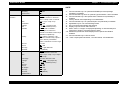
EPSON EPL-N1600
MENU Button
PS Menu*1
ESCP2 Menu
FX Menu
Chapter 1
ITEM Button
Err Sheet
MicroGray
Protect Level
OFF / ON
ON / OFF
1-5
Font
Courier / Prestige / Roman /
Sans serif / Roman T / Orator S /
Sans H / Script / OCR A / OCR B
10cpi / 12cpi / 15cpi / Prop.
OFF / ON
0.40 - 0.5 - 1.50 (step:0.05")
1 - 66*4 - available (max 81)
PcUSA / Italic / PcMultilin /
PcPortugue / PcCanFrenc /
PcNordic / PcTurkish2 / PcE.Europe
BpBRASCII / BpAbicomp
USA / French / Germany / UK /
Denmark / Sweden / Italy / Spain1 /
Japan / Norway / Denmark2 /
Spain2 / LatinAmeric / Korea / Legal
ON / OFF
OFF / ON
Dark / Light / BarCode
0, 0 (slashed)
Pitch
Condensed
T.Margin
Text
CGTable
Country
Auto CR
Auto LF
Bit Image
ZeroChar
I239X Menu
Font
Pitch
Code Page
T.Margin
Text
Auto CR
Auto LF
Alt. Graphic
Bit Image
ZeroChar
CharacterSet*4
Rev. A
VALUE Button
Product Description
NOTE:
*1:
Can be selected only if an optional EPSONScript Level2 package
(C83229*) is installed.
*2: Can be selected only when an optional Type-B interface card is installed.
*3: Can be selected only if the optional lower cassette unit (C812902) is
installed.
*4: Factory default varies depending on the destination.
*5: Can be selected only if an optional Duplex unit (C812932) is installed.
*6: Applicable only for LJ4 and ESC/Page mode.
*7: Do not change automatically after printing.
*8: Display only and cannot select the size.
*9: Either "Pitch" or "Height" is displayed depending on the selected pitch:
Fixed pitch="Height", Proportional pitch="Pitch"
*10: Additional symbol sets will be displayed if an optional font ROM is
installed.
*11: Can be selected only in GL/Like mode.
*12: "100%" capacity:MP=80 sheets, LC1=250 sheets, LC2=500sheets
Courier / Prestige / Gothic / Orator /
Script / Presentor / Sans serif
10cpi / 12cpi / 15cpi / 17cpi / 20cpi /
24cpi / Prop.
437 / 850 / 860 / 863 / 865
0.30 - 0.40 - 1.50 (step:0.05")
1 - 67*4 - available (max 81)
OFF / ON
OFF / ON
OFF / ON
Dark / Light
0, 0 (slashed)
1/2
30
EPSON EPL-N1600
Chapter 1
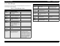
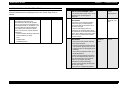
1.4.2 Printer Status Messages
Message
Reset to Save
The table below lists the printer status messages that are displayed on
the LCD panel.
Service Req. effff *1
ROM check
Type
Service-call error
Status
RAM check
Paper Jam
Warning
Face Up print off
Check Paper Size
Image Optimum
Need Memory
Status
Warming Up
Reset
Exiting Paper Jam
Menus Locked (at panel setting operation)
Form Feed (during test prinitn)
Reset All
Check Duplex P-Size
Status
Writing DIMM A
Format Error DIMM A
Self Test
Duplex Unit Fail
Type
Duplex print was off
Table 1-14. Error Message
Message
Product Description
Error
Toner Low
Standby
Warning
Satus
Ready
*1:
Refer to Chapter-3 Troubleshooting for detail.
Feed Jam
Paper Jam in Duplex
Jam in Duplex Tray
The order of list is corresponding to a priority of message and the list
starts from the high priority order.
Jam in Duplex Cover
Insert Imaging Crtg
Printer Open
Duplex Cover Open
Insert Duplex Tray
Manual Feed xxx yyyy
Insert LC1
Paper Out sssss tttt
Paper Set sssss ttttt
Print Overrun
Illegal Aux I?F Card
Mem Overflow
Duplex Mem Overflow
Illegal DIMM A
Write Error DIMM A
Rev. A
31
EPSON EPL-N1600
Chapter 1
Product Description
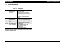
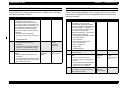
1.4.3 Initialization Process
The following tables shows the process carried out for each of the
printer's three initialization types.
Table 1-15. Initialization
Type
Trigger
Processing
Reset
Press "Continue" button
while holding down
"ALT" button
• Cancels all data processing and all
completed print jobs.
• Deletes all data stored in the receive
buffer for the currently active interface.
(Retains data for other interfaces.)
• Clears error condition.
Use this reset operation to cancel multiplecopy printing or to abort inappropriate
printing.
Warm Boot
Press "Continue" button
while holding down
"ALT" button and hold
them for specified period
of time.
Terminates printing jobs and executes reset
for all interfaces. The printer returns to its
initial power-on state; but does not repeat
power-on self tests
• Initialize memory.
• Clear receive buffers for all interfaces.
Cold Start
Executed at power-on.
(Power-on initialization)
•
•
•
•
•
Initialize engine.
Check ROM/ EEPROM and RAM.
Check peripheral devices.
Initialize memory.
Initialize peripheral devices.
For all three reset types, the printer will enter READY state upon normal
termination of reset processing.
Rev. A
32
EPSON EPL-N1600
Chapter 1
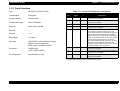
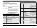
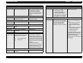
1.4.4 Special Functions
Table 1-16. .Special Function
Mode/Operation
Built-in special fucntion can be selected by turning on the printer while
holding down the specific combination of button(s). The table below
explains each operation
C A U T IO N
All special functions (with the exception of hex dumps)
are intended for service technicians only and are not
documented in the user manual. Please handle these
operations with due care.
Note that to activate the operation you must continue to hold the buttons
down until the LCD indicates that "RAM check" is completed
Product Description
Buttons
Result
Hex-Dump Mode
Form Feed
Once this mode is activated, the printer
prints a hex dump of all received codes
and data. To cancel this mode, you must
switch the printer off.
Initialize EEPROM*1
• Online
• Continue
• Menu
Clears all EEPROM content, then writes
factory settings into EEPROM. (Also
initializes total page count.)
Initialize panel
settings*1
Continue
Resets all panel settings (common
environment settings and interfacespecific settings) to their factory defaults.
Clear total page count*1 • Online
• Menu
• Item
Clears the total page count to 0.
Force-erase the flashROM module*1
Deletes content of flash ROM module in
slot A.
•
•
•
•
ALT
Item
Value
Enter
Update program ROM*1 • Online
• ALT
• Value
Updates content of ROM-DIMM in
program sockets.
Copy ROM module*1
• Online
• ALT
• Enter
Copies content of ROM module in slot B
into ROM module in slot A.
Toner Counter Reset
• Online
• Form Feed
Reset the toner counter value to "Full"
status.
Maintenance Mode *1
• Online
• Form Feed
• Continue
The maintenance menu item is added to
the setting menu.
*1: For details, refer to Chapter 4 "Disassembly and Reassembly"
Rev. A
33
EPSON EPL-N1600
Chapter 1
Product Description
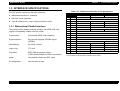
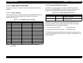
1.4.5 OTHER SPECIFICATIONS
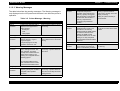
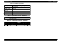
1.4.5.2 Program-ROM Specifications
This section presents information related to product distribution and
handling.
The printer's control program is provided on a ROM board which
mounts into the ROM-DIMM slot on the main board. The printer will
include one of the ROM boards indicated in the table below.
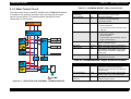
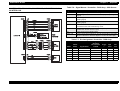
1.4.5.1 Jumper Settings
Table 1-18. Program ROM Specification
The main control circuit board of this printer (C258MAIN) includes four
jumper switches. Set the switches in accordance with product
destination, as follows.
Name
No.
C215PROG
• Flash PROM
• 8Mbit x 4 (IC 3/4/5/6)
Board Subassembly
C258PROG
• Mask ROM
• 16Mbit x 2 (IC 1/2)
Table 1-17. C258MAIN Jumper Settings
Jumper
Standard *1
Latin America
Russia
RJ1
Installed
Installed
Installed
RJ3
Not installed
Not installed
Not installed
RJ4
Not installed
Not installed
Not installed
RJ5
Installed
Not installed
Installed
RJ6
Not installed
Installed
Not installed
RJ7
Not installed
Not installed
Not installed
RJ8
Not installed
Not installed
Not installed
RJ9
Not installed
Not installed
Not installed
RJ10
Not installed
Not installed
Not installed
RJ11
Installed
Installed
Installed
RJ12
Not installed
Not installed
Not installed
RJ13
Installed
Installed
Installed
RJ14
Not installed
Not installed
Not installed
JP2
1 - 2 pin connected
1 - 2 pin connected
1 - 2 pin connected
JP3
Connected
Connected
Connected
Specification
Board Subassembly
Specifically, the ROM board will be flash-type during initial mass
production (so that it can be updated locally), but will be changed to
mask-ROM type when production stabilizes.
At start of mass production:
C215PROG board
When production becomes stable:
C258PROG board
The C215PROG board (flash ROM) can be updated using the printer's
"progarm-ROM update" feature. Refer to Chapter 5, "Adjustments," for
more information.
NOTE: *1:Applicable for all destinations except for Latin America
and Russia.
Rev. A
34
EPSON EPL-N1600
Chapter 1
Product Description
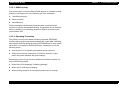
1.4.5.3 RAM Capacity
If the printer does not have sufficient RAM capacity to complete normal
printing, it will display one of the following two error messages.
"Insufficient memory"
"Mem Overflow"
"Need Memory"
These messages indicates that the printer does not have enough
memory to execute the specified printing. The problem can be resolved
either by installing (or increasing) expansion RAM or by reducing the
receive-buffer size.
1.4.5.4 Operating Precaution
The printer's control circuit board includes nonvolatile (EEPROM)
memory that is used to store printer settings and control data. Switching
off the power while the printer is writing to EEPROM may in some cases
cause loss or corruption of EEPROM content, resulting in one of the
following errors.
At next power-on, the printer generates a service-call error.
When user executes a warm boot ("full reset") from the control
panel, the printer initializes the panel settings.
Accordingly, power should never be switched off while the printer is in
any of the following states.
When the LCD is displaying "Initializing Settings".
When the On Line lamp is blinking.
When printing operation is in progress (while motor is running).
Rev. A
35
OPERATING PRINCIPLES
EPSON EPL-N1600
Chapter 2
Operating Principles
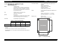
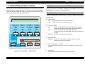
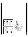
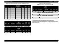
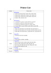
2.1 OVERVIEW
2.1.1 Electrophotographic Printing
This chapter explains the functions and operating principles of engine
mechanism and controller of the EPL-N1600.
Like other EPSON page printers, the EPL-N1600 also using the
electrophtographic prinitng system combined with a semi-conductor
laser beam scanning system, as illustrated below.
.
Figure 2-1. Electrophotographic Process Components
Rev. A
38
EPSON EPL-N1600
Chapter 2
Operating Principles
Table 2-1. Electrophotographic Printing Process
Step
Process
Explanation
1
Charging
In this process, electric discharge from the BCR (Bias Charge Roll) generates a uniform negative charge on the surface of the OPC (Organic
Photconductor) drum located within the Imaging Cartridge.The BCR is a conductive roller positioned in contact with the OPC drum, The HVPS ASSY
applies a bias voltage (a negative DC bias voltage superposed on an AC voltage) to the BCR. The AC voltage is controlled by constant-current regulation
and the current level is apporx. 800µA (850Hz). This AC component evens out the residual charge left on the OPC drum during the previous print cycle,
so that a uniform negative charge corresponding to the DC bias voltage level (approx. -400VDC) is generated over the entire drum surface.
2
Exposure
In this process, the ROS (Raster Output Scanner) ASSY generates the latent image onto the OPC drum surface by scanning the drum with the laser. The
scanner motor rotates the polygon mirror within the ROS ASSY. The mirror reflects the laser beam produced by the laser diode so that the beam scans
across the drum surface. The OPC drum surface consists of a photoconductive layer covering an aluminum (conductor) base. As the beam strikes the
surface it generates electrons and holes within the photoconductive layer. The electrons are pulled by the electric field into the conductor base, while the
holes move to the outside surface of the photocondutor layer (the outside of the drum), combining with the surface electrons and reducing the surface
charge (increasing the potential). This action occurs only at the areas illuminated by the beam. The result is that the negative charge at the illuminated
areas is lower than the negative charge at the non-illuminated areas. This charge differential constitutes the latent image. The SOS (Start of Scan)
sensor attached at the side of MIRROR M1 detects the scan start position (by detecting the laser illumination at the scan start area).
3
Development
This process applies toner to the drum surface to generate the visible image. This printer utilizes non-conductive dry single-component magnetic toner.
Toner adheres to a surface of the MAG ROLL by magnetic force, while the narrow gap between the CM (Charging and Metering) blade keeps this toner
coating extremely thin and uniform. The friction between the CM blade and the MAG ROLL generates a negative charge on the toner. A negative DC
voltage (approx. -315VDC) superposed on an AC voltage (approx. 1.8KVp-p at 3.0KHz) is applied to a thin semiconductive sleeve that covers the MAG
ROLL, as a developing bias (DB). The DC component of the bias keeps the MAG ROLL at negative potential with respect to the OPC drum’s conductive
layer and the AC component of the development bias serves to facilitate the transfer of the toner on the MAG ROLL. As a consequence, the parts of the
drum surface that were not hit by the laser beam (the areas where the negative charge was not reduced) will have lower potential than the MAG ROLL,
while the parts that were hit by the laser beam will have higher potential. Because the toner on the MAG ROLL is negatively charged, it will transfer to the
OPC drum only at those areas where the potential on the drum is higher than the potential on the MAG ROLL, thereby forming the visible image.
4
Transfer
This process transfers the visible image formed by a toner on the OPC drum surface, to the paper. This printer utilizes a BTR (Bias Transfer Roller) to
effect the transfer. The BTR is a conductive roller that is in positioned in contact with the OPC drum. When the paper moves be tween the OPC drum and
the BTR, the BTR applies an HVPS-generated positive charge (+700VDC) to the back side of the paper. This pulls the toner image off the drum surface
and onto the paper.
5
Separation
In the separation process, the action of the negatively charged DETACH SAW neutralizes a positive charge remained on the paper which causes the
paper to stick to the drum surface, so that the paper comes free of the drum. Specifically, an HVPS-generated negative voltage (-2.0KVDC) is applied to
the DETACH SAW.
6
Fusing
This process fuses the toner image (the image transferred onto the paper in the transfer process) to the paper. This printer uses a HEAT ROLL to fuse
the image to the paper. The HEAT ROLL is heated by an internal heater lamp. A PRESSURE ROLL is positioned in contact with the HEAT ROLL. When
paper passes between the HEAT ROLL and PRESSURE ROLL, the application of heat and pressure fuses the toner to the paper.
7
Cleaning
In this process, a cleaning plate attached to the OPC drum scrapes residual toner (the toner that not transfered to the paper) off the drum surface. The
toner scraped off from the drum surface is collected in the waste-toner compartment within the Imaging Cartridge.
In addition to the above explained cleaning operation, the BTR surface is also cleaned electrically. At the initialization cycle of the printer operation or
before starting a print job, a negative charge (approx. -600VDC) is applied to the BTR and the toner sticking on the BTR surface is transferred from the
BTR to the drum by this voltage.
Rev. A
39
EPSON EPL-N1600
Chapter 2
Operating Principles
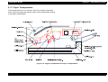
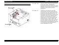
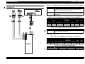
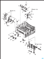
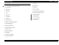
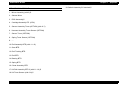
2.1.2 Paper Transportation
The illustration below is a cut-section view of the engine mechanism
and it shows the paper path and the major engine components relating
to the paper transportation.
Figure 2-2. Engine Components for Paper Transportation
Rev. A
40
EPSON EPL-N1600
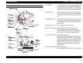
2.1.3 Main Engine Components Function
Chapter 2
Paper Cassette:
Universal paper cassette that can hold six
regular sizes of plain paper cut sheets up to 250
sheets. Adjusting the Back Stopper makes the
Actuators on the left side of the Cassette in a
combination corresponding to the position of the
Back Stopper. The Actuators press their
corresponding prongs of the Spring Size, which
in turn actuate the corresponding Paper Size
Switches of the Sensor Assembly-Size 1.
PWB ASSY.-Size 1:
The board has three Paper Size Switches 1 to 3.
Each Switch is actuated by the corresponding
prong of the Spring Size when the prong is
pressed by the corresponding Actuator on the
Paper Cassette. The pattern of actuated
Switches identifies the size of the paper that is
loaded in the Cassette. When the Cassette is
not in place, all Switches are not actuated, and
the printer can detect removal of the Cassette.
Refer to Paper Size Detection in Section 13 for
the relationship between paper sizes and
patterns of actuated Paper Size Switches.
Spring Size:
The Spring Size is pressed by the
corresponding Actuators on the left side of the
Paper Cassette, and the psring is then pressing
the corresponding paper size switchs.
This section explains the structure and operation ofeach part of the
engine mechanism.
PAPER CASSETTE (STANDARD)
Rev. A
Operating Principles
41
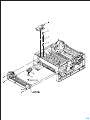
EPSON EPL-N1600
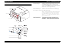
PAPER TRANSPORTATION I
Chapter 2
Operating Principles
Drive ASSY. :
This unit distributes a drive that transmitted from
the main motor, to Feed Rolls (Roll Assembly
Feed and Roll Assembly MBF), Turn Rolls (Roll
Assembly Turn), and also to the optional units
Solenoid Feed:
Releases the drive gear of the Roll Assembly
Feed to allow the gear to rotate when actuated
and latches the gear when the gear rotates one
turn.
Roll Assembly Feed:
Rotates one turn each time the Solenoid Feed is
actuated. The Roll Assembly Feed pushes one
sheet of paper out of the Paper Cassette during
each rotation.
Rolls Assembly Turn: Drives paper fed into the printer.
Sensor Pre-Registration and Actuators Pre-Registration A / B:
Detect when a paper reaches the position
before the Sensor Registration. The signal from
this sensor is used for paper jam detection.
Sensor Registration and Actuator Registration:
Detect when a paper reaches the position just
before the EP Cartridge Drum. The signal from
the Sensor Registration is used as the reference
timing signal for generating the P.SYNC (Page
Synchronization) signal inside the MCU. The
signal from this sensor is also used for paper
jam detection.
Sensor No Paper and Actuator No Paper:
Detect when the Paper Cassette is out of paper.
Rev. A
42
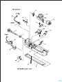
EPSON EPL-N1600
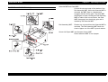
PAPER TRANSPORTATION I REAR
Chapter 2
Operating Principles
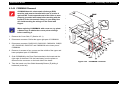
Chute Exchange:
Switches the paper path between the exit to the
Face Down Delivery Tray on the top of the
Cover Assembly Exit and the exit to the optional
Duplex Unit or Face Up Catch Tray.
Solenoid Exchange:
Switches the position of the Chute Exchange.
Sensor Photo and Actuators Exit-2/L and 2/S:
These Actuators and Sensor detect when paper
passes the position just before the exit to the
Face Down Delivery Tray. This Sensor Photo
(PL3.2.8) is also called Sensor Exit-2 or Exit-2
Sensor in this manual.
Gear Duplex ASSY.:
Rev. A
Transmits the drive power generated by the
Drive ASSY. Main to the optional Duplex Unit.
43
EPSON EPL-N1600
PAPER TRANSPORTATION II (1)
Chapter 2
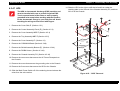
Lever Jam Clear:
Operating Principles
This lever is pressed down by the Cover
Assembly Exit and presses the Roll Pinch PreRegistration against the Roll Assembly Turn.
When the Cover Assembly Exit is open, the
Lever Jam Clear is released and releases the
Roll Pinch Pre-Registration. This makes jam
clear easier.
Roll Pinch Pre-Registration:
This pinch roll is pressed against the Roll
Assembly Turn by the Cover Assembly Exit by
means of the Spring-Hold Rod, Stopper Rod,
and Spring NIP Pre-Registration to drive paper
in cooperation with the Roll Assembly Turn.
Rev. A
44
EPSON EPL-N1600
PAPER TRANSPORTATION II (2)
Chapter 2
Operating Principles
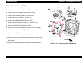
Solenoid MBF and Gear MBF:
Control the start and stop of the rotation of the
Roll Assembly MBF. When the Solenoid MBF is
actuated, the MBF Gear is unlatched and
engages with the driving gear. The Gear MBF
then begins to rotate, causing the Roll Assembly
MBF to rotate. After one revolution, the Gear
MBF disengage from the driving gear and is
latched by the Solenoid MBF.
Roll Assembly MBF:
Rotates one turn each time the Solenoid MBF is
actuated. The Roll Assembly MBF feeds one
sheet of paper out of the MBF by each rotation.
Sensor No Paper MBF and Actuator Sensor MBF:
Detect when the MBF is out of paper.
Rev. A
45
EPSON EPL-N1600
FUSING AND PAPER EXIT
Rev. A
Chapter 2
Operating Principles
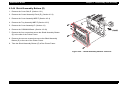
Sensor Assembly Photo Exit and Actuator-Exit:
Detect when paper passes the position just after
the Fuser.
Roll Pressure:
A roll with sponge rubber attached around a
metal shaft. The Roll Pressure is pressed up by
the springs and applies pressure to the paper
passing between itself and the Roll Fuser.
Fuser Unit:
Roll Fuser:
A hollow, surface-coated metal tube that is
heated by the Heater lamp held inside the roller.
The toner on the paper is melted and bonded to
the paper by means of heat and pressure
applied by the rollers.
Heater Lamp:
A glass tube with a heat generating coil sealed
in it. The Heater Lamp is located inside the Roll
Fuser and heats the Roll Fuser.
Sensor Assembly Temperature:
A resistor (thermistor) whose resistance varies
sharply in a known manner with the
temperature. This sensor is held in contact with
the surface of the Roll Fuser and monitors the
temperature. The signal from this sensor is used
to maintain the temperature of the surface of the
Roll Fuser within the specified range by
switching on and off the AC power to the Heater
Lamp. The signal is also used for the first-stage
overheat protection.
46
EPSON EPL-N1600
Chapter 2
Operating Principles
Thermostat:
Connected in series with the Heater Lamp. The
Thermostat functions as the second-stage
overheat protection. If the first stage fails to
prevent a Fuser overheat, the Thermostat opens
the power supply circuit to the Heater Lamp.
This Thermostat opens at about 160 °C (inside
temperature).
Fuse:
A thermal fuse connected in series with the
Heater Lamp. The Fuse functions as the thirdstage overheat protection. If both the first and
second stages fail to prevent a Fuser overheat,
the Fuse opens the power supply circuit to the
Heater Lamp. This Fuse melts at about 141 °C.
Rev. A
47
EPSON EPL-N1600
XEROGRAPHIC MODULES
Chapter 2
ROS ASSY:
Operating Principles
The ROS (Raster Output Scanner) Assembly
scans a laser beam on the drum surface. The
ROS Assembly consists of two major
components: PWBA LD and Scanner Assembly.
Basic Operation:
The Laser Diode (LD) of the PWBA LD emits
laser light. The LD is switched on and off
according to the print image signal during
printing. The power of the laser light is
monitored by the monitor circuit and controlled
to be a constant power. The laser light from the
LD is shaped and converged into a very thin
beam by means of a slit and a Cylinder Lens,
and directed to a Polygon Mirror. The Polygon
Mirror has six facets and is rotated at a constant
speed by the Scanner Motor. These facets
reflect the laser beam in turn as the Polygon
Mirror rotates. The laser beam reflected by the
Polygon Mirror passes through a Correction
Lens L1 and is reflected by a Mirror M1 onto the
drum surface, moving from one end of the Drum
to the other. The laser beam is thus scanned
one line by each facet of the Polygon Mirror.
LD Output Power Control:
The drive current of the LD is switched on and
off by the Current Switching Circuit in the LDD
(Laser Diode Driver) according to the print
image signal (/PDATA) from the engine control
circuit. The LD drive current while the LD is on is
precisely determined by the two DC voltage
signals (VLI and VL2) from HMCU. The laser
power is monitored using a monitor signal (MO),
Rev. A
48
EPSON EPL-N1600
Chapter 2
which is generated by converting the current
flowing through the monitoring Photodiode (PD)
integrated in the LD into an analog output
voltage by means of a resistor.
Scanner Motor Control:
The Polygon Mirror is rotated by the Scanner
Motor (also called ROS Motor). The Scanner
Motor is driven at a constant speed by the
Scanner Motor Drive Circuit using a phaselocked loop (PLL).
Mirror ASSY:
The Mirror Assembly consists of Mirror M1,
Shutter and PWBA SOS.
Mirror M1:
Reflects the laser light beam from the ROS to
the Drum.
PWBA SOS:
Generates a SOS (Start of Scan) signal. The
laser beam hits a photosensor on the PWBA
SOS at the beginning of each scan, and the
PWBA SOS generates a pulse signal (/SOS).
The /SOS signal is used as the reference timing
signal for generating LINE SYNC signal.
Shutter Mirror:
The Mirror Assembly has a Shutter Mirror (A)
covering or exposing the Mirror M1 and lens of
the SOS Sensor. When the Cover Assembly
Exit is open, a projection of the Cover pushes
down the crank arm of the Shutter to raise the
Shutter and expose the Mirror M1 and lens of
the SOS Sensor. When the Cover Assembly
Rev. A
Operating Principles
Exit is open or the Mirror Assembly is removed,
the Shutter covers the Mirror M1 and lens of the
SOS Sensor to prevent them from collecting
dust.
Imaging Cartridge
The Imaging Cartridge is composed of following
components.
Drum:
An aluminum cylinder with a coating of
photoconductive material on the surface. The
photoconductive coating (layer) holds an
electrical charge placed on the surface while in
darkness, and allows the charge to flow through
into the conductive layer when exposed to laser
light.
BCR (Bias Charge Roll):
Places a uniform electrical charge on the drum
surface, erasing any patterns of decreased
charge remaining from the previous cycle.
Magnet Roll:
Holds toner on the surface in a thin layer and
transports it to the gap between the drum and
the Magnet Roll. Toner is supplied to the
Magnet Roll from the Toner Compartment.
CM Blade (Charging and Metering Blade):
Spreads toner on the Magnet Roll in a thin layer,
and also gives toner a negative charge.
Cleaning Blade:
Scrapes the toner remaining after the Transfer
step off of the Drum surface.
49
EPSON EPL-N1600
Chapter 2
BTR:
The BTR (Bias Transfer Roll) is in contact with
the Drum and rotates along with the Drum being
driven by the Drum Gear. The BTR applies a
positive charge to the back side of the paper
when the paper travels between the BTR and
the Drum. The toner image transfers from the
Drum surface to the front side of the paper being
attracted by the positive charge on the back side
of the paper.
Sensor Toner:
A magnetic sensor that detects when toner is
low in the Toner Compartment of the Imaging
Cartridge. (Amount of toner is monitored by both
Sensor Toner and a software counter, and
“Toner Low” message is displayed whenever
the condition is detected by Sensor Toner, prior
to the status of software counter.)
Operating Principles
Switch Assembly 5V Interlock:
Detects the closing of the Cover Assembly Exit
as illustrated in figure below. The signal is used
in the control circuit for the Printer.
Rev. A
50
Rev. A
EPSON EPL-N1600
Chapter 2
51
Operating Principles
EPSON EPL-N1600
DRIVE MODULES
Rev. A
Chapter 2
Operating Principles
Drive ASSY. Main:
Includes the Motor Assembly Main (Main Motor)
and the Gear Cluster. The Main Motor
generates the drive power, and the Gear Cluster
distributes the drive power to the Roll Assembly
Registration, Drum and BTR, and Drive
Assembly-F/P.
Drive ASSY.-F/P:
Transmits the drive power from the Drive
Assembly Main to the Roll Assembly Exit Out
and the Roll Fuser (also called Heat Roll), Roll
Assembly Exit, and optional Duplex Unit. The
transmission of the drive power to the Roll Fuser
is switched on and off by a floating idler gear.
When the Cover Assembly Exit is closed, a
molded tab of the Cover presses down on the
floating idler gear to engage it with the Roll
Fuser gear. When the Cover is open, the tab of
the Cover releases the floating idler gear. The
floating idler gear then disengages from the Roll
Fuser driving gear and interrupts the drive
power transmission to the Fuser.
52
EPSON EPL-N1600
ELECTRICAL MODULES
Chapter 2
Operating Principles
Fan IOT:
Expels the air inside the printer and introduces
fresh air into the printer to prevent an excessive
rise of the inside temperature.
HPS:
Has the Main Power Switch, Interlock Switch,
Sensor Registration, Sensor Pre-Registration,
Sensor No Paper, LVPS (Low Voltage Power
Supply) circuit, and HVPS (High Voltage Power
Supply) circuit on it. The HPS also has the
switching circuit to switch on and off AC power
to the Heater Lamp of the Fuser Unit.
Interlock Switch:
Opens the 24 VDC circuit from the LVPS to the
controller when the Cover Assembly Exit is
open.
LVPS:
Produces regulated low DC voltages (5V
supplied to logic circuits, 5V-LD supplied to the
Laser Diode, and 24V supplied to motors,
solenoids, and clutches) from the AC power.
HVPS:
Produces high AC and DC voltages used for
charge (BCR), development (Magnet Roll),
transfer (BTR), and detack (Detack Saw) in the
print process.
C258MAIN Board:
Rev. A
This is a main control circuit of the EPL-N1600
and contains two major circuits: image
processing main control circuit and MCU
(Machine Control Unit) which directly controls all
printer operations responding to signals from the
main control circuit.
53
EPSON EPL-N1600
FRAME
Chapter 2
Operating Principles
Actuator Assembly Link Interlock Switch, and Link Interlock Switch:
When the Cover Assembly Exit is closed, a
molded projection of the Cover Assembly Exit
presses down the Actuator Assembly Link
Interlock Switch, which in turn press the Link
Interlock Switch to the Interlock Switch. The
Interlock Switch is therefore held On when the
Cover Assembly Exit is closed. When the Cover
Assembly Exit is open, the Actuator Assembly
Link Interlock Switch is released, and the Link
Interlock Switch is moved away from the
Interlock Switch by the force of the spring. The
Interlock Switch is therefore Off when the Cover
Assembly Exit is open.
Drum Shaft Latching: Guide R (A), Guide R (B), and Spring. When the
Cover Assembly Exit is closed, a molded
projection of the Cover Assembly Exit pushes
down the Guide R (A). The EP Cartridge is thus
held in place by the Guide R (A) in cooperation
with the Guide R (B). When the Cover Assembly
Exit is opened, the Lever Latch is pulled up by
the Spring to turn the Latch Shaft away from the
Dram Shaft, releasing the EP Cartridge.
Latches L/R and Latch Shaft:
Hold the Cover Assembly Exit in the closed
position.
Rev. A
54
EPSON EPL-N1600
Chapter 2
2.1.4 Main Control Circuit
Table 2-2. C258MAIN BOARD - Main Control Circuit
Component
The main control circuit of the EPL-N1600 is the C258MAIN Board and
it consists of two sections: the main control circuitry and the engine
control circuitry (MCU). The following tables describe the main
components of each section.
Operating Principles
Location
Operation
CPU (VR4310)
µPD30200GD
IC1
A RISC CPU running at 150MHz. Controls
the board’s main control section.
ASIC E05B41BA
IC10
Controls the following:
• Memory access (RAM/ROM)
• DMA (I/O, Video)
ASIC E05B40BA
IC15
Controls the following:
• External interfaces
• Communication with the operation panel
• Interrupts
ASIC E05B28KA
IC16
Controls the following:
• Video data generation
• RIT/PGI operation
• Video interface (communication with the
engine control section)
DRAM
IC19-22
Two 16Mbit ((16) modules. Serve as the
system’s standard memory.
Mask ROM
IC17/18
8Mbit mask ROM. Stores font dataand IPL.
Program ROM
CN5
Either C215PROG (Flash ROM version) or
C215PROG-B (Mask-ROM version) ROMDIMM module is installed in ROM-DIMM
socket CN5.
EEPROM (NM93C86A)
IC13
16Kbit EEPROM which saves printer
configurations and status.
Table 2-3. C258MAIN BOARD - Engine Control Circuit (MCU)
Component
Location
Operation
CPU (PD78054)
IC201
Engine control CPU. Controls engine
components (implements printing) in
accordance with video data from the main
control section.
ASIC (PD65622GF)
IC202
Controls the video interface with the main
control section. Also controls EEPROM.
EEPROM
(AT93C45)
IC203
Capacity is 16Kbit. Stores setup parameters
related to engine control.
Figure 2-3. CIRCUIT BLOCK DIAGRAM - C258MAIN BOARD
Rev. A
55
TROUBLESHOOTING
EPSON EPL-N1600
Chapter 3
3.1 OVERVIEW
This section describes the possible steps to troubleshoot and repair the
printer. Due to a complexity of the laser printer, most effective approch
to troubleshoot the problem is either checking the printer in accordance
with the error message displayed by the printer or the printed image
quality.
Table 3-1. Service-Call Errors
Error
Type
“e”
Error
Code
“ffff”
E
(Engine)
0003
Fusing ASSY. Problem
0004
ROS Assy. Problem
0005
Fan Motor Problem
0008
EEPROM Failure (in Engine Control Circuit)
0014
Communication Error (between main control circuit and
engine control circuit)
0017
CPU Error (undefined interrupt)
0081
CPU Error (TLB modification exception)
0082
CPU Error (TLB mistake exception [Load/Fetch])
0083
CPU Error (TLB mistake exception [Store])
0084
CPU Error (address error exception [Load/Fetch])
0085
CPU Error (address error exception [Store])
0086
CPU Error (bus error exception [Fetch])
0087
CPU Error (bus error exception [Load/Store])
0088
CPU Error (SYSCALL exception)
0089
CPU Error (Break exception)
0090
CPU Error (Reserved instruction exception)
0091
CPU Error (coprocessor unused exception)
0092
CPU Error (FPU exception)
0093
CPU Error (TLB exception)
0094
CPU Error (XTLB exception)
0095
CPU Error (cache exception)
0096
CPU Error (Trap exception)
0097
CPU Error (FPU exception)
0098
CPU Error (watch exception)
3.1.1 Service-Call Errors
This printer has a built-in diagnostic function and If the printer detects
an error which is not recoverable by the user, the printer displays
“Service Req” message with corresponding error type code. You can
identify the problem by referring to the type of error and a component
identified as defective is need to be replaced to new one to solve the
problem. The table shown in right lists the Service-Call errors.
Rev. A
Troubleshooting
C
(Controller)
Description
0128
CPU Error (undefined trap)
0129-0254
CPU Error (undefined trap)
0255
CPU Error (NMI exception)
0256
CPU Error (division by zero)
0257
CPU Error (processing overflow)
0258
CPU Error (break generated)
58
EPSON EPL-N1600
Error
Type
“e”
Error
Code
“ffff”
C
(Controller)
0800
Rev. A
Chapter 3
Troubleshooting
Description
IPL Error (controller failure)
1000
Standard RAM Error (no RAM, etc.)
1001
Standard RAM Error (no minimum stack area, etc.)
1002
Standard RAM Error (less than standard size, etc.)
1003
Expansion RAM Error
1100
ROM Checksum Error (bit0 - 15) (Font)
1101
ROM Checksum Error (bit16 - 31) (Font)
1120
ROM Checksum Error (bit0 - 7) (Program)
1121
ROM Checksum Error (bit 8 -15) (Program)
1122
ROM Checksum Error (bit16 - 23) (Program)
1123
ROM Checksum Error (bit24-31) (Program)
1170
Option FONT ROM Checksum Error
1180
Option ROM Module A Checksum Error
1181
Option ROM Module B Checksum Error
1185
Unsupported ROM Module
1200
EEPROM Write Error
1210
EEPROM Write Count Limit Error
1400
Printer Engine Initialization Failure
1999
Other Hardware Error
2000
Software Error
59
EPSON EPL-N1600
Chapter 3
3.1.2 Printer Messages
Priority
The LCD panel of the control panel unit is used to display various printer
status and error condition. There are three types of message displayed
by the printer: Status Message, Error Message and Warning Message.
The table below lists all messages displayed by the printer. The order of
list is corresponding to a display priority of each message.
Table 3-2. Printer Messages
Priority
Higher
Rev. A
Message
Type
Service Req. effff
Service-call error
ROM check
Status
RAM check
Staus
Self Test
Status
Reset All
Status
Reset
Status
Duplex Unit Fail
Error
Check Duplex P-Size
Error
Exiting Paper Jam
Error
Paper Jam
Error
Feed Jam
Error
Paper Jam in Duplex
Error
Jam in Duplex Tray
Error
Jam in Duplex Cover
Error
Insert Imaging Crtg
Error
Printer Open
Error
Duplex Cover Open
Error
Insert Duplex Tray
Error
Manual Feed xxx yyyy
Error
Insert LC1
Error
Paper Out sssss tttt
Error
Paper Set sssss ttttt
Error
Print Overrun
Error
Illegal Aux I?F Card
Error
Lower
Troubleshooting
Message
Type
Mem Overflow
Error
Duplex Mem Overflow
Error
Illegal DIMM A
Error
Write Error DIMM A
Error
Reset to Save
Status
Writing DIMM A
Status
Menus Locked (at panel setting operation)
Warning
Duplex print was off
Warning
Face Up print off
Warning
Check Paper Size
Warning
Image Optimum
Warning
Need Memory
Warning
Format Error DIMM A
Warning
Form Feed (during test prinitn)
Status
Warming Up
Status
Toner Low
Warning
Standby
Satus
Ready
Status
60
EPSON EPL-N1600
Chapter 3
3.1.2.1 Status Messages
LED
The table below shows the Status message displayed by the printer and
the meaning of each message.
Table 3-3. Printer Message - Status
LED
Description
Action
ROM check
Online:
Continue:
The printer is checking
checksumm and format of
program ROM.
-----
Online:
Continue:
The printer is checking function
and capacity of RAM memory.
-----
Onlin:
Continue:
The printer is performing
diagnostics and initialization
process.
-----
The warm-boot process is in
progress. When the warm-boot
process completes, the
message is changed to “Reset”
and perform the reset
operation.
-----
The reset process is in
progress.
-----
The panel settings is changed
by the panel setting mode
during print job process.
The mesage is cancelled by one
of the following operation:
• Press Online button and the
panel settings is cacelled. The
printer is back to Readt state.
• Perform Reset or Warm-boot
process. The panel settings
becomes valid and all print
jobs are cancelled.
The printer is writing data to the
ROM module
*Do not remove the module or
turn the printer off while the
printer is writing the data.
The printer is priting the
remaining print job.
-----
One of READY state message.
The printer is in warm-up
process.
-----
The printer is not ready to start
printing operation.
Press Online button to back to
Ready state.
The printer is in stand-by state
(Power save mode).
-----
Form Feed
Online:
Continue:
Warming Up
Offline
Standby
Online:
Continue:
Reset All
Online:
Continue:
Online:
Continue:
Online: OFF
Continue:
Self Test
Action
Writing DIMM A
Online:
Continue:
RAM check
Description
Troubleshooting
Reset
Online:
Continue:
Reset to Save
Online: OFF
Continue:
Rev. A
61
EPSON EPL-N1600
Chapter 3
3.1.2.2 Error Messages
LED
The table below lists the error messages and an operation to be
performed. When any error state is detected by the printer, the Online
LED goes off and the Conitnue LED indicates the following three
conditions.
Continue LED = OFF: If the error condition can be removed, the printer
restarts automatically without pressing the
Continue button.
Continue LED = Blink: The printer restarts when the Continue button is
pressed. If “Auto-Cont” is ON in the device
menu, the error status is cancelled automatically
after the specified period of time has passed.
Continue LED = ON:
The printer restart only when the Continue
button is pressed after removing the error.
Description
Onlin:OFF
Continue:OFF
The duplex unit becomes
unvalid during power on.
Online: OFF
Continue: OFF
Online: OFF
Continue: Blink
Online: OFF
Continue: OFF
Turn the printer off and re-install
the duplex unit.
Rev. A
Occurs only during duplex
Set correct paper in the printer
printing, if “Size Ignore=Off” has and press Continue button. Then
been selected in Device menu. restart printing.
The paper loaded is shorter
than the paper size specified for
printing.
If the error occur at first face
printing, the printer eject the
sheet without printing next face.
A paper jam has occured at the
Fusing process.
Open the top cover and remove
the imaging cartridge. Then
remove jammed paper inside the
printer.
The error state will be cancelled
automatically by closing the top
cover and the printer resume the
printing after warm-up.
A paper jjam has occured at the
image transfer process.
Open the top cover and remove
jammed paper.
The error state will be cancelled
automatically by closing the top
cover and the printer resume the
printing after warm-up
A paper jam has occured at the
paper entrance.
If another paper jjam has
occured at thhe same time, the
error message displayed on the
LCD will be the one
corresponding to another paper
jam, such as “Paper Jam”.
Open the top cover and check for
any jammed paper at the paper
entrance.
The error state will be cancelled
only when the top cover is
closed. The printer wil resume
printing after warm-up.
Feed Jam
Action
Check Duplex P-Size
Action
Paper Jam
Duplex Unit Fail
Online: OFF
Continue: OFF
Description
Exiting Paper Jam
Table 3-4. Printer Message - Error
LED
Troubleshooting
Paper Jam in Duplex
Online: OFF
Continue: OFF
A paper jam hhas occured in
the Duplex Unit.
Open the Duplex Unit and
remove any jammed paper.
The error state will be concelled
automatically by closing the
Duplex Unit.
Jam in Duplex Tray
Online: OFF
Continue: OFF
A paper jam has occured in the
Duplex Tray.
Take out the Duplex Tray and
remove jammed paper. The error
state will be cancelled by
reinstalling the Duplex Tray.
The printer resume printing from
first face after warm-up.
62
EPSON EPL-N1600
LED
Chapter 3
Description
Action
Jam in Duplex Cover
Online: OFF
Continue: OFF
A paper jam has occured in a
rear cover of the Duplex unit.
LED
Open the top cover and install
the imaging cartridge.
Paper Set sssss tttt
The top cover is open.
Close the top cover.
A rear cover of the Duplex Unit
is open.
Close the cover.
The tray is not set inside the
Duplex Unit.
Reinstall the tray.
Manual Feed xxx yyyy
Online: OFF
Continue: Blink
Set specified size of paper in the
seletced paper supply.
The imaging cartridge is not
installed in the printer.
Insert Duplex Tray
Online: OFF
Continue: OFF
This error occurs when:
• no paper is available in the
selected paper supply.
• no paper is available in all
connected paper suppy
units. If the error occurs with
this condition, the message
will display “LC1” as sssss.
Online: OFF
Continue: OFF
Duplex Cover Open
Online: OFF
Continue: OFF
Action
Paper Out sssss tttt
Printer Open
Online: OFF
Continue: OFF
Description
Open the Duplex Unit and
remove any jammed paper. The
error state will be concelled
automatically by closing the
Duplex Unit. The printer resume
printing from the first face after
warm-up.
Insert Imaging Crtg
Online: OFF
Continue: OFF
Troubleshooting
If “Manual Feed=On” has been
selected, this error occurs when
the printer receives the print
job.
xxx:
Paper supply source
yyyy: Paper size
Do one of the following:
• Set the paper in specified
paper supply and press either
Online or Continue button. The
printer prints with the specified
paper supply and indicates the
same error again at next page
printing.
• Press either Online or
Continue button. The printer
feeds a paper from the paper
supply with highest priority.
• Perform Reset or Warm-boot.
Standard cassette is not set in
the printer.
Reinstall the paper cassette.
Online: OFF
Continue: Blink
In case if ‘Size Ignore=Off” has
been selected in Config. Menu,
this error occur when the paper
size in the selected paper
supply and the paper size
specified for printing is different.
1. If “Auto Cont=OFF”:
The error can be cancelled by
either:
• Press Continue button after
putting a specified size of
paper in the selected paper
supply
• Press Continue button without
changing the paper in the
selected paper supply.
2. If “Auto Cont=ON”:
In this case, the error is cancelled
automatically after passing the
specified period of time, and the
printer resume printing by
feeding a paper from the selected
paper supply.
Insert LC1
Online: OFF
Continue: OFF
Rev. A
63
EPSON EPL-N1600
LED
Chapter 3
Description
Action
Print Overrun
Online: OFF
Continue: Blink
LED
Description
Troubleshooting
Action
Mem Overflow
Due to complexity of print job
data, the printer is unable to
continue the data process and
causing an overrun.
1. If “Auto Cont=OFF”:
The error can be cancelled by
either:
• Press Continue button causes
the printer to retry printing with
all available vacant memory. If
no memory left or printing
failed again, the
corresponding page is deleted
and processing the next page.
• Perform Rest or Warm-boot,
and retry printing by setting
“Auto Cont=ON”.
2. If “Auto Cont=ON”:
In this case, the error is cancelled
automatically after passing the
specified period of time, and the
printer retry priting as case-1)
above.
Online: OFF
Continue: Blink
Memory capacity become
insufficient during the data
process.
1. If “Auto Cont=OFF”:
The error can be cancelled by
either:
• press Continue button and a
printer operation is different
afterwards depending on the
cause of error. If a buffer
overflow is a cause of error, a
command causing the error is
discarded and the page
processed already is ejjected.
If the error occurs when
processing the first face of
duplex print data, the page is
ejected with only first face
printed, and a second face is
printed on next page. In case if
the error occurs while
registering a Macro-pattern, a
command causing the error is
discarded and the printer
continue the process.
Invalid AUX I/F Card
Online: OFF
Continue: OFF
Rev. A
The optional I/F card which is
not supported by this printer, is
installed.
Turn the printer off and remove
the I/F card.
• perform Reset or Warm-boot.
2. If “Auto Cont=ON”:
In this case, the error is cancelled
automatically after passing the
specified period of time, and the
printer operates as case-1).
64
EPSON EPL-N1600
LED
Chapter 3
Description
Troubleshooting
Action
Duplex Mem Overflow
Online: OFF
Continue: Blink
The available memory is
insufficient to process the data
for second face of duplex
printing.
The printer only prints first face
and eject the page.
1. If “Auto Cont=OFF”:
The error can be cancelled by
either:
• Press Continue button causes
the printer to reprocess the
data for second face and print
it on the second face of nnext
page.
• Perform Rest or Warm-boot,
and retry printing by setting
“Auto Cont=ON”.
2. If “Auto Cont=ON”:
In this case, the error is cancelled
automatically after passing the
specified period of time, and the
printer print a second face as
case-1) above.
Invalid ROM A
Online: OFF
Continue: OFF
Unusable ROM module is
installed.
(i.e ROM module that not being
formatted and write-protected,
or defective one.)
Turn the printer off and remove
the ROM module.
Write Error ROM A
Online: OFF
Continue: OFF
Rev. A
The printer tried to write on
write-protected ROM module,
or writing operation was
incomplete. Or ROM module is
not installed in Slot-A.
Perform wither::
• Turn the printer off and
remove the ROM module
• Perform Reset-All operation.
65
EPSON EPL-N1600
Chapter 3
3.1.2.3 Warning Messages
LED
The table below lists the warning messages. The Warning message is
only displayed on the LCD panel and the state is not affect the printer’ s
operation.
Online:
Continue:
Table 3-5. Printer Message - Warning
LED
Description
Action
Duplex Print was Off
Online:
Continue:
Printing was performed with a
paper that not supported for
duplex printing.
• Envelopes
• OHP
• Thick papers
Press Continue button to cancel
the warning.
Face up exit is selected when
printing with Gov. Legal or
Legal size paper.
The printed page is forcibly
ejected at Face down exit.
Press Cotinue button or perform
Reset / Warm-boot to cancel the
warning.
This warning is only displayed
when “Size Ignore=OFF” has
been selected. The paper
actually fed is shorter than the
paper size for printing. The
warning do not appear with the
following papers:
Press Continue button to cancel
the warning or perform Reset or
Warm-boot.
Press Continue button to cancel
warning or perform Reset or
Warm-boot to forcibly cancel the
image processing.
Adding an optional memory is
recommended.
Online:
Continue:
This warning occurs when
installed ROM module is not
formatted. If this warning
displayed with the ROM module
to which the data has been
written, the ROM module
should be defective or the data
writing is not fully completed,
and the ROM module should be
removed.
Press Continue button or turn off
the printer and remove the ROM
module.
The amount of remaining toner
is decreased. The amount of
toner is calculated by software.
Press Continue button to cancel
the warning.
Toner Low
Online:
Continue:
Check Paper Size
Online:
Continue:
The printer performs memory
compression/expansion
operation when detecting low
memory capacity during print
data processing. This warning
occurs when the number of
memory compression is
exceeding the predefined
number.
Action
Format Error ROM A
Face Up print off
Online:
Continue:
Description
Troubleshooting
DL/C5/COM10/Monarch/A5/
Half Letter/Government Letter/
F4/C6International B5/Custom
Image Optimum
Online:
Continue:
Due to insufficient memory
capacity, printing was unable to
complete at the specified
resolution.
Press Continue button to cancel
the warning or perform Reset or
Warm-boot to forcibly cancel the
printing process.
Need Memory
Rev. A
66
EPSON EPL-N1600
Chapter 3
Troubleshooting
3.2 Troubleshooting
3.2.1 Troubleshooting with Error Messages
The basic troubleshooting is divided into three catogories and the
procdures to follow for proceeding the troubleshooting is outlined in the
flowchart shown below.
1.1 SERVICE REQ E0008
Read or write error is occured with the EEPROM on the Engine control
circuit.
Step
Actions and Questions
Yes
No
SUSPECT COMPONENTS
The following components are
associated with this specific problem.
One or more of these components may
have failed partially or completely. If you
cannot isolate the problem using this
FIP, replace each component listed
below, one at a time, until the problem
disappears.
• C258MAIN BOARD
1
Switch printer power on and off several
times.
Does this error occur whenever printer
power is switched on?
Replace the
C258MAIN
Board.
-----
Figure 3-1. Troubleshooting Flow
Rev. A
67
EPSON EPL-N1600
Chapter 3
Troubleshooting
1.2 SERVICE REQ E0004
Step
The ROS (Raster Output Scanner) Assy. is defective.
Step
Actions and Questions
Yes
3
No
SUSPECT COMPONENTS
The following components are
associated with this specific problem.
One or more of these components may
have failed partially or completely. If
you cannot isolate the problem using
this FIP, replace each component listed
below, one at a time, until the problem
disappears.
• Harness Assembly ROS
• Harness Assembly SOS
Actions and Questions
+5 VDC POWER SUPPLY
1. Remove the Cover Side, and then
C258MAIN board.
2. Check the voltage between:
-FG and J31-A10
-FG and J31-A11
-FG and J31-B11
Yes
Replace the
C258MAIN.
No
Replace the
HPS.
Is there +5VDC between:
FG and J31-A10
FG and J31-A11
FG and J31-B11?
1
SCANNER MOTOR
Unplug J27 (Main Drive Motor) from
CN227 of the C258MAN and J222
(Fan) from the HPS.
1. Run a test print.
2. Listen for the sound of the Scanner
Motor.
Can you hear the Scanner Motor
running before the U2 code appears?
Go to step 3.
Replace the
ROS Assembly.
2
LASER DIODE POWER
1. Remove the Main Cover.
2. Remove the Lever Jam Clear.
3. Switch on printer power.
4. Cheat the Main Interlock Switch.
5. Do not unplug P/J262.
6. Check the voltage between P262-7
and P262-5 on the PWB LD.
Replace the
ROS Assembly.
Go to step 4.
Note:
Since there is no convenient test point
on the HPS to check for +5VDC, this
step has you check four separate
+5VDC voltages that run from the HPS
through the PWBA Hotaru and on to the
C258MAIN through J31. Although not a
foolproof test, it should give you some
indication of whether or not the +5VDC
portion of the HPS is working correctly.
Failure to read +5VDC on any of the
test points most likely reflect a HPS
failure, but in some cases an PWBA
Hotaru or C258MAIN failure may give
you the same readings.
Is there +5 VDC between P262-5 and
P262-7?
Rev. A
68
EPSON EPL-N1600
Chapter 3
Step
1.3 SERVICE REQ E0003
Actions and Questions
Yes
1
2
TEMPERATURE SENSORS
1. Unplug J292 from P/J291.
2. Check the continuity between the two
black wires on J292 (Leading to the
Sensor Assembly Temperature).
3. Check the continuity between the two
white wires on J292 (leading to the
Sensor Assembly Temperature).
Are there a few hundreds ohms between
the two black wires and between the two
white wires on J292?
Go to step 2.
HEATER LAMP CIRCUIT
1. Unplug the AC power cord from the
AC wall outlet.
2. Unplug J11 from the HPS.
3. Check the continuity between the two
wires on J11.
Is there continuity (approximately 2.5Ω)
between the two wires on J11?
Go to step 6.
Rev. A
Replace the
Sensor
Assembly
Temperature.
Go to step 3.
No
HEAT LAMP
Go to step 4.
1. Remove the Heater Lamp.
2. Check the continuity between the two
ends of the Heat Rod.
Is there continuity (approximately 2.5Ω)
between the two ends of the Heat Lamp?
Replace the
Heater Lamp.
4
FUSE
Check the continuity between the two
ends of the Fuse.
Is there continuity (0Ω) between the two
ends of the Fuse?
Go to step 5.
Replace the
Fuse
5
THERMOSTAT
Check the continuity between the two
ends of the Thermostat.
Is there continuity (0~2Ω) between the
two ends of the Thermostat?
Go to step 6.
Replace the
Thermostat.
6
HEATER LAMP POWER SUPPLY
Replace
1. Reinstall the Fuser, if it was removed C258MAIN
BOARD.
during a previous step.
2. Switch ON printer power.
3. Check the voltage between the two
wires on P/J11.
Is there 90~132VAC (110VAC model) or
198~264VAC (220VAC model) even
momentarily between the two wires on P/
J11 before the U4 code appears?
No
SUSPECT COMPONENTS
The following components are
associated with this specific problem.
One or more of these components may
have failed partially or completely. If you
cannot isolate the problem using this
FIP, replace each component listed
below, one at a time, until the problem
disappears.
• Fuser Assembly
Yes
3
The Fuser Assy. is defective.
Step
Actions and Questions
Troubleshooting
Replace the
HPS with new
one.
69
EPSON EPL-N1600
Chapter 3
Troubleshooting
1.4 SERVICE REQ E0005
Fan IOT unit or Duplex Unit Fan is in trouble.
Step
Actions and Questions
Yes
No
SUSPECT COMPONENTS
The following components are
associated with this specific problem.
One or more of these components may
have failed partially or completely. If you
cannot isolate the problem using this
FIP, replace each component listed
below, one at a time, until the problem
disappears.
• Fan IOT
• Fan Assembly Duplex
• HPS
• PWBA Hotaru
• C258MAIN Board
1
FAN IOT
Does the Fan rotate when you switch on
printer power?
Go to step 3.
Go to step 2.
2
FAN SIGNAL
1. Disconnect P/J222 from the HPS.
2. Check the voltage between P/J222-3
and P/J222-1.
Is there +12~24VDC between P/J222-3
and P/J222-1?
Replace the
Fan.
Replace the
HPS.
3
PWBA HOTARU
Replace the
C258MAIN
1. Remove the PWBA Hotaru.
2. Check for the continuity between P21- Board.
B2 and P31-B12.
Is there continuity between P21 and
P31?
Rev. A
Replace the
PWBA Hotaru.
70
EPSON EPL-N1600
Chapter 3
Step
1.5 ERROR MESSAGE “PRINTER OPEN”
Actions and Questions
SUSPECT COMPONENTS
The following components are
associated with this specific problem.
One or more of these components may
have failed partially or completely. If you
cannot isolate the problem using this
FIP, replace each component listed
below, one at a time, until the problem
disappears.
• Interlock Switch actuating mechanism
• Interlock Switch (on HPS)
• HPS
• PWBA Hotaru
• C258MAIN Board
Rev. A
Yes
Yes
No
1
INTERLOCK SWITCH ACTUATOR
TAB ON COVER ASSEMBLY EXIT
Is the actuator tab in place on the Cover
Assembly Exit; not damaged nor
deformed?
Go to step 2.
Replace the
Cover
Assembly Exit.
2
INTERLOCK SWITCH ACTUATING
MECHANISM
Press down on the Actuator Interlock
Switch directly by a small-diameter
screwdriver through the inside hole of
the Spring Actuator.
Is there a small clicking sound of
actuation of the Interlock Switch when
you press down on the Actuator Interlock
Switch, and is there a slow spring-action
return when you release the Actuator
Interlock Switch?
Go to step 3.
Replace the
HPS with new
one.
3
INTERLOCK SWITCH ACTUATING
MECHANISM
1. Remove the Link Interlock Switch &
Cam Interlock Switch.
2. Inspect the Actuator Interlock Switch,
Cam Actuator, Spring Cam, and Link
Interlock Switch for disengagement or
breakage.
3. Also check the Interlock Switch by a
Digital Multi Meter.
-Is there continuity between terminals 1
and 2 of the Interlock Switch when you
press the hinged arm of the Interlock
Switch? If not, replace the HPS.
-Reinstall the Actuator Assembly
Interlock Switch replacing broken parts
with new one, if any.
Does this error message still appear?
Replace the
C258MAIN
Board.
Problem
solved.
Check if the above error displayed even if the Cover Assy. Exit is
closed.
Step
Actions and Questions
Troubleshooting
No
71
EPSON EPL-N1600
Chapter 3
Troubleshooting
1.6 ERROR MESSAGE “EXITING PAPER JAM”
1.7 ERROR MESSAGE “PAPER JAM”
Check if this error message appears even if no paper Jam in the paper
exit section has been occured.
Check if this message appears even if no paper jam over the Sensor
Registration or between the Sensor Registration and the Sensor Exit
has been occured.
Step
Actions and Questions
Yes
No
SUSPECT COMPONENTS
The following components are
associated with this specific problem.
One or more of these components may
have failed partially or completely. If you
cannot isolate the problem using this
FIP, replace each component listed
below, one at a time, until the problem
disappears.
• Actuator-exit and Sensor Exit
• Actuators Exit-2L/2S and Sensor Exit2
• C258MAIN Board
Step
1
ACTUATOR-EXIT AND SENSOR EXIT
• Does the Actuator-exit move
smoothly?
• Is the output level of the Sensor Exit at
CN226-2 on the C258MAIN change
when you actuate the actuator-exit?
Go to step 2.
Replace the
Sensor
Assembly
Photo Exit.
4
ACTUATOR EXIT-2L/2S AND SENSOR
EXIT-2
• Do the Actuators Exit-2L/2S move
smoothly?
• Is the output level of the Sensor Exit 2
at CN226-5 change when you actuate
the actuator exit-2L/2S?
Replace the
C258MAIN
Board.
Replace the
Sensor Photo.
Rev. A
Actions and Questions
Yes
No
SUSPECT COMPONENTS
The following components are
associated with this specific problem.
One or more of these components may
have failed partially or completely. If
you cannot isolate the problem using
this procedure, replace each
component listed below, one at a time,
until the problem disappears.
• Roll Registration Assembly and Roll
Pinch Registration
• Fuser Assembly
• Actuator-Exit and Sensor Exit
• Drive Assembly Main
• Drive Assembly-F/P
• PWBA Hotaru
• C258MAIN Board
1
Does the jammed sheet of paper reach
the Sensor Exit?
Go to step 2.
Go to step 3.
2
ACTUATOR-EXIT AND SENSOR
EXIT
• Does the Actuator-exit move
smoothly and have a spring action
return?
• Is the output level of the Sensor Exit
at CN226-2 on the C258MAIN
change when you actuate it?
Replace the
C258MAIN
Board.
Replace the
Sensor
Assembly Photo
Exit.
3
PAPER CONDITION
Is the paper in the Paper Cassette or
MBF wrinkled or damp?
Replace the
paper with
fresh, dry paper.
Go to step 4.
72
EPSON EPL-N1600
Step
Actions and Questions
Chapter 3
Yes
No
4
PAPER SIZE AND WEIGHT
Are the size and weight of the paper
used within the paper specification?
Go to step 5.
Use paper within
the specification.
5
DRIVE ASSEMBLY MAIN
Does the Main Motor run and do the
gears of the Drive Assembly rotate
normally?
Go to step 6.
Replace the
Drive Assembly
Main.
ROLL ASSEMBLY REGISTRATION
• Is the Roll Pinch Registration in
place and pressed against the Roll
Registration Assembly by the Spring
Nip Registration?
• Is the Roll Registration Assembly
clean and free of damage or
excessive wear?
Go to step 7.
ACTUATOR REGISTRATION
Does the Actuator Registration move
freely, with a slight spring-action
return?
Go to step 8.
8
SENSOR REGISTRATION ON HPS
Is the output level of the Sensor
Registration at CN221-21 change when
you press the Actuator?
Replace the
C258MAIN
Board.
Go to step 9.
9
PWBA HOTARU
1. Remove the PWBA Hotaru (RRP
7.2.1).
2. Check for continuity between P21B6 and P31-B8.
Is there continuity between P21 and
P31?
Replace HPS.
Replace the
PWBA Hotaru.
DETACK SAW
Inspect the Detack Saw.
Is the Detack Saw clean and free of
contamination?
Go to step 11.
6
7
10
Rev. A
Reseat the Roll
Pinch
Registration or
replace the Roll
Assembly
Registration.
Correct the
problem, or
replace the
Actuator if the
problem cannot
be corrected.
Step
Actions and Questions
Troubleshooting
Yes
No
11
ROLL FUSER
1. Remove the Fuser Assy.
1. Rotate the Fuser Drive Gear.
Does the Roll Fuser rotate smoothly?
Go to step 12.
Replace the
Fuser Assy.
12
ROLL-PRESS
Rotate the Roll-Press.
Does the Roll-Press rotate smoothly?
Go to step 13.
Replace the
Roll-Press or
BearingPressure Roll.
13
ROLL ASSEMBLY EXIT AND ROLLPINCH
Do the Roll Assembly Exit and RollPinch rotate smoothly?
Go to step 14.
Replace the
Fuser Assy.
14
GUIDE L
(Slidably held on the left side of the
Frame between the Mirror Assembly
and the Roll Assembly Exit)
Does the Roll Fuser drive gear rotate
when you press down on the Guide L?
Go to step 15.
Replace the
Drive AssemblyF/P.
15
EXIT GUIDE LINK ACTUATOR
• Locate the Guide Link actuator tab
that is molded on the Cover
Assembly Exit.
Is the actuator tab in place on the
Cover Assembly Exit; not damaged nor
deformed?
Run test prints.
Replace the
Cover Assembly
Exit.
• Slowly close the Cover Assembly
Exit and observe the actuator tab.
Does the actuator tab press down on
the Guide Link?
Clean the
Detack Saw.
73
EPSON EPL-N1600
Chapter 3
Step
1.8 ERROR MESSAGE “INSERT IMAGING CRTG”
Actions and Questions
Yes
1
Remove and reinstall the imaging
Cartridge.
Does this error message still appear?
No
Reseat the HPS to make sure that the
conductor strips for applying the
voltages of the HPS to the BCR,
Magnet Roll, and BTR are in complete
contact with the corresponding
conductors on the HPS.
Does this error message still appear?
Go to step 3.
Problem
solved.
3
PWBA HOTARU (PL7.2.4)
1. Remove the PWBA Hotaru.
2. Check for the continuity between:
Go to step 4.
Replace PWBA
Hotaru.
Replace the
HPS.
Problem
solved.
No
SUSPECT COMPONENTS
The following components are
associated with this specific problem.
One or more of these components may
have failed partially or completely. If you
cannot isolate the problem using this
FIP, replace each component listed
below, one at a time, until the problem
disappears.
• PWBA Hotaru
• C258MAIN Board
Yes
2
Check if this error message is displayed even if the imaging cartridge is
already installed in the printer.
Step
Actions and Questions
Troubleshooting
P21-A9 andP31-A5
P21-A10 and P31-A4
P21-A11 and P31-A3
P21-B7 and P31-B7
Go to step 2.
P21-B8 and P31-B6
Problem
solved.
P21-B9 and P31-B5
P21-B10 and P31-B4
P21-B11 and P31-B3
P21-B13 and P31-B1
Is there continuity between P21 and
P31?
4
Rev. A
C258MAIN Board
Replace the C258MAIN Board.
Does this error message still appear?
74
EPSON EPL-N1600
Chapter 3
Troubleshooting
1.9 ERROR MESSAGE “INSERT LC1”
This error message is displayed when the printer detects that the upper
Paper Cassette is not in place. If this error message is displayed though
the upper Paper Cassette is installed, locate and eliminate sources of
the problem following the procedure below.
Step
Actions and Questions
Yes
No
SUSPECT COMPONENTS
The following components are
associated with this specific problem.
One or more of these components may
have failed partially or completely. If you
cannot isolate the problem using this
FIP, replace each component listed
below, one at a time, until the problem
disappears.
• Paper Cassette
• Size Switches on the Sensor
Assembly-Size 1
• C258MAIN Board
1
PAPER CASSETTE
Inspect the Actuator that are located on
the side of the Paper Cassette.
IS the Actuator intact, not chipped nor
broken?
Go to step 2.
Replace the
Paper Cassette
with new one.
2
SIZE SWITCHES
• Do the Size Switches function
correctly?
• Is the signal level at CN224-9 change
when you press and release each
prong of the Spring Size?
Replace the
C258MAIN
Board.
Replace the
Senor
Assembly Size1.
Rev. A
75
EPSON EPL-N1600
Chapter 3
3.2.2 Troubleshooting with Printer Operation
Step
Actions and Questions
Yes
1
AC POWER CORD
Inspect the AC Power Cord.
Go to step 2.
Is the AC Power Cord plugged into the
back of the printer, and is the other end
plugged into an AC wall outlet?
2
AC POWER
Check the voltage at the wall outlet.
Go to step 5.
Replace the
HPS.
5
+5 VDC POWER SUPPLY
Go to step 6.
1. Remove the C258MAIN.
2. Check the voltage between:
P31-A10 and FG
P31-A11 and FG
P31-B11 and FG
Is there +5VDC between P31 and FG?
Replace the
HPS
Troubleshoot
the AC power
at the wall
outlet for a
possible tripped
breaker or
open circuit.
Go to step 5.
Go to step 4.
Is there approximately 110 VAC (or 220
VAC for the 220 VAC model) at the AC
wall outlet?
3
Rev. A
+24VDC POWER SUPPLY
1. Remove the C258MAIN.
1. Slide the PWBA Hotaru out about an
inch so it disconnects from the HPS.
1. Switch ON Main Power.
1. Inspect the Fan IOT.
Is the Fan rotating?
Connect the
AC Power Cord
to the printer,
and plug it into
a wall outlet.
Go to step 3.
No
+24VDC POWER SUPPLY
1. Slide the PWBA Hotaru out about an
inch so it disconnects from the HPS.
2. Disconnect the Fan IOT from P/J222.
3. Switch ON Main Power.
4. Check the voltage between P/J222-3
and P/J222-1.
Is there +24VDC between P/J222-3 and
P/J222-1?
No
SUSPECT COMPONENTS
The following components are
associated with this specific problem.
One or more of these components may
have failed partially or completely. If you
cannot isolate the problem using this
FIP, replace each component listed
below, one at a time, until the problem
disappears.
• No recommendations
Yes
4
2.1 PRINTER DOES NOT OPERATE PROPERLY
Step
Actions and Questions
Troubleshooting
Note:
Since there is no convenient test point
on the HPS to check for +5VDC, this
step has you check four separate
+5VDC voltages that run from the HPS
through the PWBA Hotaru and on to the
C258MAIN through J31. Although not a
foolproof test, it should give you some
indication of whether or not the +5VDC
portion of the HPS is working correctly.
Failure to read +5VDC on any of the test
points most likely reflect a HPS failure,
but in some cases an PWBA Hotaru
failure may give you the same readings.
6
PWBA HOTARU
1. Remove the C258MAIN.
2. Check the voltages between:
P31-A10 and FG
P31-A11 and FG
P31-B11 and FG
Is there +5VDC between P31 and FG?
Go to step 7.
Replace the
PWBA Hotaru.
76
EPSON EPL-N1600
Step
7
Actions and Questions
HPS
Chapter 3
Yes
Go to step 8
No
Replace HPS.
Step
9
1. Remove Cover Assembly Main.
2. Disconnect J222 of the Fan IOT from
the HPS.
3. Check the voltage between P/J222-3
and P/J222-1
Is there +24VDC between P/J222-1 and
P/J222-3?
Note:
Steps 8 through 16 attempt to isolate a faulty component that might be loading down
the Power Supply.
8
C258MAIN Board
1. Reinstall the C258MAIN leaving all
the connectors disconnected.
2. Check the voltages between:
CN231-A10 and FG
CN231-A11 and FG
CN231-B11 and FG.
Is there +5VDC between CN231 and
FG?
1. Check the voltage between P/J222-3
and P/J222-1
Is there +24VDC between P/J222-1 and
P/J222-3?
Rev. A
Go to step 9.
Replace the
C258MAIN
Board.
Actions and Questions
DRIVE ASSEMBLY MAIN
1. Reconnect J27 of the Main Motor to
CN227 of the C258MAIN.
2. Check the voltages between:
CN231-A10 <=> FG
CN231-A11 <=> FG
CN231-B11 <=> FG
Is there +5VDC between CN231 and
FG?
Troubleshooting
Yes
No
Go to step 10.
Replace the
Drive Assembly
Main.
Go to step 11.
Replace the
ROS
Assembly.
1. Check the voltage between P/J222-3
and P/J222-1
Is there +24VDC between P/J222-1 and
P/J222-3?
10
ROS ASSEMBLY
1. Reconnect J23 to CN223 of the
C258MAIN.
2. Check the voltages between:
CN231-A10 and FG
CN231-A11 and FG
CN231-B11 and FG
Is there +5VDC between CN231 and
FG?
1. Check the voltage between P/J222-3
and P/J222-1
Is there +24VDC between P/J222-1 and
P/J222-3?
77
EPSON EPL-N1600
Step
11
Actions and Questions
SOS ASSEMBLY
1. Reconnect J22 to CN222 of the
C258MAIN.
2. Check the voltages between:
CN231-A10 and FG
CN231-A11 and FG
CN231-B11 and FG
Is there +5VDC between CN231 and
FG?
Chapter 3
Yes
Troubleshooting
No
Go to step 12.
Replace the
Mirror
Assembly.
Go to step 13.
Replace the
Solenoid
Exchange.
1. Check the voltage between P/J222-3
and P/J222-1.
Is there +24VDC between P/J222-1 and
P/J222-3?
12
SOLENOID EXCHANGE
1. Reconnect J25 to CN225 of the
C258MAIN.
2. Check the voltages between:
CN231-A10 and FG
CN231-A11 and FG
CN231-B11 and FG
Is there +5VDC between CN231 and
FG?
1. Check the voltage between P/J222-3
and P/J222-1
Is there +24VDC between P/J222-1 and
P/J222-3?
Rev. A
78
EPSON EPL-N1600
Step
13
Actions and Questions
SENSOR ASSEMBLY-SIZE 1
1. Reconnect J24 to CN224 of the
C258MAIN.
2. Check the voltages between:
CN231-A10 <=> FG
CN231-A11 <=> FG
CN231-B11 <=> FG
Is there +5VDC between CN231 and
FG?
Chapter 3
Yes
Go to step 14.
No
Replace the
Sensor
Assembly- Size
1.
1. Check the voltage between P/J222-3
and P/J222-1
Is there +24VDC between P/J222-1 and
P/J222-3?
14
SENSOR ASSEMBLY
TEMPERATURE
1. Reconnect J28 to CN228 of the
C258MAIN.
1. Check the voltages between:
CN231-A10 and FG
CN231-A11 and FG
CN231-B11 and FG
Is there +5VDC between CN231 and
FG?
Go to step 15.
Replace the
Sensor
Assembly
Temperature.
Step
15
Actions and Questions
SENSOR PHOTO AND SENSOR
ASSEMBLY PHOTO EXIT
1. Reconnect J26 to CN226 of the
C258MAIN.
2. Check the voltages between:
CN231-A10 and FG
CN231-A11 and FG
CN231-B11 and FG
Is there +5VDC between CN231 and
FG?
Troubleshooting
Yes
Check for other
wirings.
No
Replace the
Sensor Photo
or the Sensor
Assembly
Photo Exit.
1. Check the voltage between P/J222-3
and P/J222-1.
Is there +24VDC between P/J222-1 and
P/J222-3?
1. Check the voltage between P/J222-3
and P/J222-1
Is there +24VDC between P/J222-1 and
P/J222-3?
Rev. A
79
EPSON EPL-N1600
Chapter 3
Step
2.2 ABNORMAL PRINT OPERAITON
Step
Actions and Questions
Yes
1
Does the printer enter a print cycle?
2
+5 VDC POWER SUPPLY
Go to step 3.
1. Remove the C258MAIN.
2. Check the voltage between:
P31-A10 and FG
P31-A11 and FG
P31-B11 and FG
Is there +5VDC between P31 and FG?
Go to step 3.
Yes
No
4
Does the printer still exhibit erratic
operation?
Go to step 5.
Problem
solved.
5
Replace the C258MAIN.
Does the printer still exhibit erratic
operation?
Go to step 6.
Problem
solved.
6
Execute Status Sheet printing.
Does the printer reset while making a
test print?
Go to Electrical
Noise.
-----
No
SUSPECT COMPONENTS
The following components are
associated with this specific problem.
One or more of these components may
have failed partially or completely. If you
cannot isolate the problem using this
procedure, replace each component
listed below, one at a time, until the
problem disappears.
• No recommendations
Actions and Questions
Troubleshooting
Go to step 2.
Replace the
HPS.
Note:
Since there is no convenient test point
on the HPS (PL7.1.2) to check for
+5VDC, this step has you check four
separate +5VDC voltages that run from
the HPS through the PWBA Hotaru and
on to the C258MAIN through J31.
Although not a foolproof test, it should
give you some indication of whether or
not the +5VDC portion of the HPS is
working correctly. Failure to read
+5VDC on any of the test points most
likely reflect a HPS failure, but in some
cases an PWBA Hotaru failure may give
you the same readings.
3
C258MAIN Board
Execute Status Sheet printing.
Can the printer generate a test print?
Rev. A
Go to step 4.
Replace the
C258MAIN.
80
EPSON EPL-N1600
Chapter 3
Step
2.3 ELECTRICAL NOISE
Step
Actions and Questions
Yes
1
EXTERNAL NOISE
1. Check if there is other electrical
equipment, such as electrical
generators, radio transmitters, or
devices using electrical motors, near
the printer.
2. Shut off the other electrical
equipment, or relocate the printer
away from the other devices.
Is the electrical noise problem still
present?
Go to step 2.
Permanently
relocate either
the printer or
the problem
devices.
2
AC GROUND
Check the AC wall outlet.
Is the AC wall outlet correctly wired and
grounded?
Go to step 3.
Repair the AC
wall outlet.
3
IMAGING CARTRIDGE
Replace the Imaging Cartridge.
Is the electrical noise problem still
present?
Go to step 4.
Problem
solved.
Rev. A
Yes
No
4
PLATE CONTACTS
Inspect Plate-Heat Roll and Plate
Contacts RTN, CR, BTR, DB, and DTS.
Are all of these Plate Contacts in place,
not bent or deformed, and does each
Plate Contact make secure contact with
the associated HPS terminal (DB, CR,
etc.)?
Go to step 5.
Repair the
damaged Plate
Contact.
5
HPS
Replace the HPS.
Is the Electrical Noise problem still
present?
Go to step 6.
Problem
solved.
6
C258MAIN Board
Replace the C258MAIN.
Is the Electrical Noise problem still
present?
Go to step 7.
Problem
solved.
7
Fuser Assy.
Replace the Fuser Assembly.
Is the Electrical Noise problem still
present?
Go to other
suspect
Components.
Problem
solved.
No
SUSPECT COMPONENTS
The following components are
associated with this specific problem.
One or more of these components may
have failed partially or completely. If you
cannot isolate the problem using this
FIP, replace each component listed
below, one at a time, until the problem
disappears.
• Duplex Unit
• Lower Cassette Unit
• Drive Assembly Main
• Solenoid Feed
• Solenoid MBF
Actions and Questions
Troubleshooting
81
EPSON EPL-N1600
Chapter 3
Troubleshooting
3.2.3 Troubleshooting with Print Image Quality
This section describes the checkpoints for troubleshooting the printer by
referring the print image quality.
Step
Problem
•
•
•
•
•
Rev. A
Plate Contact CR
Plate Contact DB
Plate Contact BTR
Plate Contact DTS
Plate Contact RTN
No
Go to Step 2.
Go to Step 3.
2
Check and correct the print density
setting with the panel setting mode
(Config. Menu).
Does the problem still persist?
Replace the
C258MAIN with
a known good
one.
Problem
solved.
3
1. Print test image and turn off the
printer halfway through the print
cycle.
2. Carefully remove the Imaging
Cartrigde and inspect the toner
image created on the OPC drum
surface just before the transfer
area (the area which comes into
contact with the BTR Roll).
Is the toner image on the OPC drum
sharp and black in the normal
density?
Go to Step .8
Go to Step 4.
4
Install a new Imaging Cartridge and
print test image.
Is the print image normal?
Problem solved.
Go to Step 5.
5
HPS OUTPUT VOLTAGES CR AND
DB TO BCR AND MAGNET ROLL
1. Reform the plate contacts CR, DB
and RTN so they make better
contacts with the Bias Charge Roll,
Magnet Roll, Drum and with the
terminals on the HPS.
2. Print test image.
Is the test print quality normal?
Problem solved.
Go to Step 6.
6
HPS
1. Replace the HPS.
2. Print test image.
Is the print image quality normal?
Problem solved.
-----
7
PAPER CONDITION
Is the paper damp?
Replace with dry
paper.
Go to Step 11.
Suspect Components
The following components are assosiated with
this specific problem. One or more of these
components may have failed partially or
completely. If you can not isolate the problem
using this procedure, replace each components
listed below, one at a time, until the problem
disappears.
Yes
Print test image.
Is the test print image normal?
3.1 LIGHT (UNDERTONE) PRINT
The overall image density is too
light.
Action and Question
1
82
EPSON EPL-N1600
Step
Action and Question
Chapter 3
Yes
No
8
IMAGING CARTRIDGE
Install a new Imaging Cartridge.
Is the print image quality normal?
Problem solved.
Go to Step 9.
9
HPS OUTPUT VOLTAGE TR TO
BTR
1. Reform the Plate Contact BTR so it
makes better contact with the HPS.
2. Print test image.
Is the print image quality normal?
Problem solved.
Go to Step 9.
10
HPS
1. Replace the HPS.
2. Print test image.
3. Is the print image quality normal?
Problem solved.
Go to Step 11.
11
BTR
1. Replace the Roll Assy. BTR.
2. Print test image.
Is the print image quality normal?
Problem solved.
-----
Rev. A
Troubleshooting
83
EPSON EPL-N1600
Chapter 3
Troubleshooting
3.2 BLANK PRINT (NO IMAGE)
Problem
The entire page is blank.
Suspect Components
The following components are assosiated with
this specific problem. One or more of these
components may have failed partially or
completely. If you can not isolate the problem
using this procedure, replace each components
listed below, one at a time, until the problem
disappears.
•
•
•
•
•
•
•
Rev. A
Plate Contact CR
Plate Contact DB
Plate Contact BTR
Plate Contact DTS
Plate Contact RTN
PWBA Hotaru
C258MAIN Board
Step
Action and Question
Yes
No
1
Print test image.
Is the test print image normal?
Go to Step 2.
Go to Step 3.
2
C258MAIN BOARD
Replace the C258MAIN with a known
good one.
Does the problem still persist?
Go to Step 4.
Problem
solved.
3
1. Print test image and turn off the
printer halfway through the print
cycle.
2. Carefully remove the Imaging
Cartrigde and inspect the toner
image created on the OPC drum
surface just before the transfer
area (the area which comes into
contact with the BTR Roll).
Is the toner image formed on the OPC
drum surface?
Go to Step .
Go to Step .
4
Install a new Imaging Cartridge and
print test image.
Is the print image normal?
Problem solved.
Go to Step 5.
5
HPS OUTPUT VOLTAGES CR AND
DB TO BCR AND MAGNET ROLL
1. Reform the plate contacts CR, DB
and RTN so they make better
contacts with the Bias Charge Roll,
Magnet Roll, Drum and with the
terminals on the HPS.
2. Print test image.
Is the density of print image normal?
Problem solved.
Go to Step 6.
6
PAPER CONDITION
Is the paper damp?
Replace with dry
paper.
Go to Step 7.
7
IMAGING CARTRIDGE
Install a new Imaging Cartridge.
Is the print image quality normal?
Problem solved.
Go to Step 8.
84
EPSON EPL-N1600
Step
Chapter 3
Action and Question
Yes
8
HPS OUTPUT VOLTAGE TR TO
BTR
1. Reform the Plate Contact BTR so it
makes better contact with the HPS.
2. Print test image.
Is the print image quality normal?
Problem solved.
Go to Step 9.
9
HPS
1. Replace the HPS.
2. Print test image.
3. Is the print image quality normal?
Problem solved.
Go to Step 10.
10
BTR
1. Replace the Roll Assy. BTR.
2. Print test image.
Is the print image quality normal?
Problem solved.
-----
Rev. A
Troubleshooting
No
85
EPSON EPL-N1600
Chapter 3
Troubleshooting
3.3 BLACK PRINT
Problem
The entire page is black.
Suspect Components
The following components are assosiated with
this specific problem. One or more of these
components may have failed partially or
completely. If you can not isolate the problem
using this procedure, replace each components
listed below, one at a time, until the problem
disappears.
•
•
•
•
•
•
•
Rev. A
Plate Contact CR
Plate Contact DB
Plate Contact BTR
Plate Contact DTS
Plate Contact RTN
PWBA Hotaru
C258MAIN Board
Step
Action and Question
Yes
No
1
Print test image.
Is the test print image normal?
Go to Step 2.
Go to Step 3.
2
C258MAIN BOARD
Replace the C258MAIN with a known
good one.
Does the problem still persist?
Go to Step 4.
Problem
solved.
3
Install a new Imaging Cartridge and
print test image.
Is the print image normal?
Problem solved.
Go to Step 4.
4
HPS OUTPUT VOLTAGES CR AND
DB TO BCR AND MAGNET ROLL
1. Reform the plate contacts CR, DB
and RTN so they make better
contacts with the Bias Charge Roll,
Magnet Roll, Drum and with the
terminals on the HPS.
2. Print test image.
Is the density of print image normal?
Problem solved.
Replace the
HPS.
86
EPSON EPL-N1600
Chapter 3
Troubleshooting
3.4 VERTICAL WHITE BANDING
Problem
There are areas of the image that
are extrreamly light or missig
entirely. These missing areas
form wide ands that runs vertically
along the paper feeding direction.
Step
Suspect Components
The following components are assosiated with
this specific problem. One or more of these
components may have failed partially or
completely. If you can not isolate the problem
using this procedure, replace each components
listed below, one at a time, until the problem
disappears.
Yes
No
PAPER CONDITIONS
Is the paper damp?
Replace with dry
paper.
Go to Step 2.
2
IMAGING CARTRIDGE
Install a new Imaging Cartridge.
Is the print image normal?
Problem solved.
Go to Step 3.
3
LASER BEAM PATH
inspect the Mirror Assy. and the laser
beam path between the ROS Assy.
and the OPC drum.
• Is a surface of the Mirror Assy.
clean?
• Is the laser beam path free of any
obstruction?
Go to Step 4.
Clean a surface
of the Mirror
Assy. or
remove any
ostructions from
laser beam
path.
4
ROLL BTR
Inspect the Roll BTR for
contamination and wear.
Is the Roll BTR free of contamination
and wear?
Go to Step 5.
Replace the
Roll Assy. BTR.
5
PAPER PATH]
Inspect the paper path throughly for
any contamination and wear.
Is the paper path clean and free of
obstaruction?
Go to Step 6.
Clean or
remove any
obstruction
from the paper
path.
6
ROLL FUSER AND ROLL PRESS
1. Remove the Fuser Assy.
2. Inspect the Roll Fuser and the Roll
Press for scratches and
contamination.
Are these Rolls free of scratches and
contamination?
Go to suspect
component.
Replace the
Roll Fuser or
the Roll Press.
• Mirror Assy.
• Fuser Assy.
• Imaging Cartridge
Rev. A
Action and Question
1
87
EPSON EPL-N1600
Chapter 3
Troubleshooting
3.5 HORIZONTAL WHITE BANDING
Problem
There are areas of the image that
are extrreamly light or missig
entirely. These missing areas
form wide ands that runs
horizontally across the paper.
The following components are assosiated with
this specific problem. One or more of these
components may have failed partially or
completely. If you can not isolate the problem
using this procedure, replace each components
listed below, one at a time, until the problem
disappears.
•
•
•
•
•
•
•
•
Rev. A
Step
Suspect Components
Plate Contact CR
Plate Contact DB
Plate Contact BTR
Plate Contact DTS
Plate Contatct RTN
Imaging Cartridge
PWBA Hotaru
C258MAIN Board
Action and Question
Yes
No
1
PAPER CONDITIONS
• Is the paper damp?
• Is the paper wrinkled?
Replace with
new, dry paper.
Go to Step 2.
2
IMAGING CARTRIDGE
Install a new Imaging Cartridge.
Is the print image normal?
Problem solved.
Go to Step 3.
3
HPS OUTPUT VOLTAGES CR AND
DB TO BCR AND MAGNET ROLL
1. Reform the plate contacts CR, DB
and RTN so they make better BCR,
Magnet Roll, OPC Drum and the
terminals on the HPS.
2. Print test image.
Is the print image quality normal?
Problem solved.
Go to Step 4.
4
HPS
1. Replace the HPS.
2. Print test image.
Is the print image quality normal?
Problem solved.
Go to Step 5.
5
HPS OUTPUT VOLTAGE TR TO
BTR
1. Reform the plate contact BTR so it
makes better contact with the
terminal on the HPS.
2. Print test image.
Is the print image quality normal?
Problem solved.
Go to Step 6.
6
HPS
1. Replace the HPS.
2. Print test image.
Is the print image quality normal?
Problem solved.
-----
88
EPSON EPL-N1600
Chapter 3
Troubleshooting
3.6 VERTICAL BLACK STREAKS
Problem
There are black lines runs
vertically along the paper feeding
direction.
The following components are assosiated with
this specific problem. One or more of these
components may have failed partially or
completely. If you can not isolate the problem
using this procedure, replace each components
listed below, one at a time, until the problem
disappears.
• Fuser Assy.
• Imaging Cartridge
Rev. A
Step
Suspect Components
Action and Question
Yes
No
1
PAPER PATH
Inspect the entire paper path for any
obstruction or contamination.
Is the paper path free of obstruciton
and contamination?
Go to Step 2.
Clean
contamination
or remove
obstruction in
the paper path.
2
IMAGING CARTRIDGE
Install a new Imaging Cartridge.
Is the print image normal?
Problem solved.
Go to Step 3.
3
ROLL FUSER AND ROLL PRESS
1. Remove the Fuser Assy.
2. Inspect the Roll Fuser and the Roll
Press for scratches and
contamination.
Are these Rolls free of scratches and
contamination?
Go to “Electrical
Noise”.
Replace the
Roll Fuser or
the Roll Press.
89
EPSON EPL-N1600
Chapter 3
Troubleshooting
3.7 HORIZONTAL BLACK STREAKS
Problem
There are areas of the image that
are extrreamly light or missig
entirely. These missing areas
form wide ands that runs
horizontally across the paper.
Rev. A
Step
Suspect Components
Action and Question
Yes
No
The following components are assosiated with
this specific problem. One or more of these
components may have failed partially or
completely. If you can not isolate the problem
using this procedure, replace each components
listed below, one at a time, until the problem
disappears.
1
IMAGING CARTRIDGE
Install a new Imaging Cartridge.
Is the print image normal?
Problem solved.
Go to Step 2.
2
Problem solved.
Go to Step 3.
•
•
•
•
•
•
•
•
HPS OUTPUT VOLTAGES CR AND
DB TO BCR AND MAGNET ROLL
1. Reform the plate contacts CR, DB
and RTN so they make better BCR,
Magnet Roll, OPC Drum and the
terminals on the HPS.
2. Print test image.
Is the print image quality normal?
3
HPS
1. Replace the HPS.
2. Print test image.
Is the print image quality normal?
Problem solved.
Go to Step 4.
4
ROLL FUSER AND ROLL PRESS
1. Remove Fuser Assy.
2. Inspect the Roll Fuser and the Roll
Press for scratches and
contamination.
Are these rolls free of scratches and
contamination?
Go to “Electrical
Noise”.
Replace the
Roll Fuser or
the Roll Press.
Plate Contact CR
Plate Contact DB
Plate Contact BTR
Plate Contact DTS
Plate Contatct RTN
Imaging Cartridge
PWBA Hotaru
C258MAIN Board
90
EPSON EPL-N1600
Chapter 3
Troubleshooting
3.8 WHITE SPOT
Problem
There are areas of the image that
are extrreamly light or missig
entirely. These missing areas
form spots that are localized to
small area of the page
Step
Suspect Components
The following components are assosiated with
this specific problem. One or more of these
components may have failed partially or
completely. If you can not isolate the problem
using this procedure, replace each components
listed below, one at a time, until the problem
disappears.
Yes
No
1
PAPER CONDITIONS
• Is the paper damp?
• Is the paper wrinkled?
Replace with a
new, dry paper.
Go to Step 2.
2
IMAGING CARTRIDGE
Install a new Imaging Cartridge.
Is the print image normal?
Problem solved.
Go to Step 3.
3
ROLL BTR
Inspect the Roll BTR for
contamination and wear.
Is the Roll BTR free of contamination
and wear?
Go to Step 4.
Replace the
Roll Assy. BTR.
4
ROLL FUSER AND ROLL PRESS
1. Remove the Fuser Assy.
2. Inspect the Roll Fuser and the Roll
Press for scratches and
contamination.
Are these Rolls free of scratches and
contamination?
Go to suspect
component.
Replace the
Roll Fuser or
the Roll Press.
• Roll BTR
• Fuser Assy.
• Imaging Cartridge
Rev. A
Action and Question
91
EPSON EPL-N1600
Chapter 3
Troubleshooting
3.9 BLACK SPOT
Problem
There are spots of toner randomly
scattered over the page.
The following components are assosiated with
this specific problem. One or more of these
components may have failed partially or
completely. If you can not isolate the problem
using this procedure, replace each components
listed below, one at a time, until the problem
disappears.
•
•
•
•
Rev. A
Step
Suspect Components
Fuser Assy.
Imaging Cartridge
PWBA Hotar
C258MAIN Board
Action and Question
Yes
No
1
IMAGING CARTRIDGE
Install a new Imaging Cartridge.
Is the print image normal?
Problem solved.
Go to Step 2.
2
ROLL FUSER AND ROLL PRESS
1. Remove the Fuser Assy.
2. Inspect the Roll Fuser and the Roll
Press for scratches and
contamination.
Are these Rolls free of scratches and
contamination?
Go to suspect
component.
Replace the
Roll Fuser or
the Roll Press.
92
EPSON EPL-N1600
Chapter 3
Troubleshooting
3.10 GHOST PRINT
Problem
There are ghost image appeared
on the image. The image may be
either ghosts of the previously
printed page or the part of the
image being printed on the
current page.
Step
Suspect Components
The following components are assosiated with
this specific problem. One or more of these
components may have failed partially or
completely. If you can not isolate the problem
using this procedure, replace each components
listed below, one at a time, until the problem
disappears.
Action and Question
Yes
1
REPETITIVE PRINTING
Inspect the ghost image.
Was the user printing numerous
copies of the same image?
Go to Step 2.
Go to Step 3.
2
Print 30 pages of various images.
Do ghost image still appear?
Go to Step 3.
Problem
solved.
Avoid printing
the same image
for many
copies.
3
IMAGING CARTRIDGE
Install a new Imaging Cartridge.
Is the print image normal?
Problem solved.
Go to Step 4.
4
ROLL FUSER AND ROLL PRESS
1. Remove the Fuser Assy.
2. Inspect the Roll Fuser and the Roll
Press for scratches and
contamination.
Are these Rolls free of scratches and
contamination?
Go to suspect
component.
Replace the
Roll Fuser or
the Roll Press.
• No recommendation
Rev. A
No
93
EPSON EPL-N1600
Chapter 3
Troubleshooting
3.11 DIRTY BACKBROUND
Problem
There is toner contamination on
all or part of the page. The
contamination appears as a very
light gray dusting.
The following components are assosiated with
this specific problem. One or more of these
components may have failed partially or
completely. If you can not isolate the problem
using this procedure, replace each components
listed below, one at a time, until the problem
disappears.
•
•
•
•
Rev. A
Step
Suspect Components
Fuser Assy.
Imaging Cartridge
PWBA Hotaru
C258MAIN Board
Action and Question
Yes
No
1
IMAGING CARTRIDGE
Install a new Imaging Cartridge.
Is the print image normal?
Problem solved.
Go to Step 2.
2
HPS OUTPUT VOLTAGES CR AND
DB TO BCR AND MAGNET ROLL
1. Reform the plate contacts CR, DB
and RTN so they make better BCR,
Magnet Roll, OPC Drum and the
terminals on the HPS.
2. Print test image.
Is the print image quality normal?
Problem solved.
Go to Step 4.
3
HPS
1. Replace the HPS.
2. Print test image.
Is the print image quality normal?
Problem solved.
Go to Step 4.
4
ROLL FUSER AND ROLL PRESS
1. Remove Fuser Assy.
2. Inspect the Roll Fuser and the Roll
Press for scratches and
contamination.
Are these rolls free of scratches and
contamination?
Go to suspec
component.
Replace the
Roll Fuser or
the Roll Press.
94
EPSON EPL-N1600
Chapter 3
Troubleshooting
3.12 SKEWED PRINTING
Problem
The image is not parallel with the
paper.
The following components are assosiated with
this specific problem. One or more of these
components may have failed partially or
completely. If you can not isolate the problem
using this procedure, replace each components
listed below, one at a time, until the problem
disappears.
• Imaging Cartridge
• Paper Cassette
• Paper Path Rolls
Rev. A
Step
Suspect Components
Action and Question
Yes
No
1
PAPER FEED
• Are the paper cassettes installed
correctly?
• Is the paper loaded into the
cassette correctly?
Go to Step 2.
Reload the
paper and reinstall the paper
cassette.
2
PAPER PATH
Inspect the entire paper path for any
ostructoion or contamination.
Is the paper path free of obstruction
or contamination?
Go to Step 3.
Clean or
remove the
obstruction in
the paper path.
3
PAPER PATH ROLLS
Inspect all rolls along the paper path
for any contamination, wear or
damage.
Are the paper path rolls free of
contamination, wear or damage?
Go to Step 4.
Replace the
damaged or
worn rolls to
new one.
4
IMAGING CARTRIDGE
Install a new Imaging Cartridge.
Is the print image normal?
Go to suspect
component.
Problem
solved.
95
EPSON EPL-N1600
Chapter 3
Troubleshooting
3.13 DAMAGED PRINTING
Problem
The printed paper is either
wrinkled, creased, or torn.
The following components are assosiated with
this specific problem. One or more of these
components may have failed partially or
completely. If you can not isolate the problem
using this procedure, replace each components
listed below, one at a time, until the problem
disappears.
• Fuser Assy.
• Paper Cassette
• Paper Path Rolls
Rev. A
Step
Suspect Components
Action and Question
Yes
No
1
PAPER FEED
• Are the paper cassettes installed
correctly?
• Is the paper loaded into the
cassette correctly?
Go to Step 2.
Reload the
paper and reinstall the paper
cassette.
2
PAPER CONDITION
Is the paper damp?
Replace with
new, dry paper.
Go to Step 3.
3
PAPER PATH
Inspect the entire paper path for any
ostructoion or contamination.
Is the paper path free of obstruction
or contamination?
Go to Step 4.
Clean or
remove the
obstruction in
the paper path.
4
PAPER PATH ROLLS
Inspect all rolls along the paper path
for any contamination, wear or
damage.
Are the paper path rolls free of
contamination, wear or damage?
Go to Step 5.
Replace the
damaged or
worn rolls to
new one.
5
FUSER ASSY.
1. Remove the Fuser Assy.
2. Inspect the surface of Roll Fuser
and Roll Press.
Are the surface of rolls free of dirt or
scracthes?
Go to Step 6.
Clean or
replace the
rolls.
6
IMAGING CARTRIDGE
Install a new Imaging Cartridge.
Is the print image normal?
Go to suspect
component.
Problem
solved.
96
EPSON EPL-N1600
Chapter 3
Troubleshooting
3.14 UNFUSED IMAGE
Problem
The image is not fully fused to the
paper. The image is easy to rub
off.
Step
Suspect Components
The following components are assosiated with
this specific problem. One or more of these
components may have failed partially or
completely. If you can not isolate the problem
using this procedure, replace each components
listed below, one at a time, until the problem
disappears.
Action and Question
Yes
No
1
PAPER CONDITION
• Is the paper damp?
• Is the paper wrinkled?
Replace with a
new, dry paper.
Go to Step 2.
4
FUSER ASSY
Replace the Fuser Assy.
Is the print image still unfused?
Replace
C258MAIN
Board.
Problem
solved.
• Fuser Assy.
• PWBA Hotaru
Rev. A
97
EPSON EPL-N1600
Chapter 3
Troubleshooting
3.15 MISREGISTRATION
Problem
The printed is not centered on the
page or is bleeding off the page.
Step
Suspect Components
The following components are assosiated with
this specific problem. One or more of these
components may have failed partially or
completely. If you can not isolate the problem
using this procedure, replace each components
listed below, one at a time, until the problem
disappears.
Yes
No
1
PAPER CONDITION
• Is the paper damp?
• Is the paper wrinkled?
Replace with
new, dry paper.
Go to Step 2.
2
PAPER FEED
Observe the paper feeding.
Is the paper fed crooked?
Go to “Skewed
Image”.
Go to Step 3.
3
PAPER PATH
Inspect the entire paper path for any
ostructoion or contamination.
Is the paper path free of obstruction
or contamination?
Go to Step 4.
Clean or
remove the
obstruction in
the paper path.
4
C258MAIN BOARD
Replace the C258MAIN and Print test
image.
Is the print image normal?
Problem solved.
-----
• PWBA Hotaru
• C258MAIN Board
Rev. A
Action and Question
98
DISASSEMBLY AND ASSEMBLY
EPSON EPL-N1600
Chapter 4
Disassembly and Assembly
4.1 OVERVIEW
This chapter explains how to disassemble the printer and its various
mechanisms. Except where otherwise indicated, the reassembly
procedure is the reverse of the disassembly procedure.
4.1.1 Precautions
This section describes the precautions you must take to prevent
accidents during disassembly and reassembly work. Be sure to carry
out all work in accordance with the precautions and general instructions
provided in this manual.
W A R N IN G
Rev. A
The following three safety switches are provided to
protect against equipment breakdown or possible
injury. DO NOT MODIFY THESE SWITCHES:
<INTERLOCK SWITCH>
This safety switch goes OFF when the Cover Assy.
Exit opens, cutting the 24V power to the control
circuitry and the engine.
<5V INTERLOCK SWITCH>
This switch goes OFF when the Cover Assy. Exit is
opened, cutting the power to the laser-diode circuit.
Make sure to unplug the printer before beginning
disassembly.
Be aware that the fuser unit remains hot for some time
after the printer goes off. Allow the unit sufficient time
to cool down before you touch it.
Take care to avoid catching hands in movable parts
(rollers, fan, etc.).
Never touch conductive areas of the printer (the HPS
ASSY primary side, the chassis, or the high-voltage
components) while the printer is plugged in.
Never remove the cover of the ROS ASSY.
C A U T IO N
Be careful to avoid injury from frame edges and other
sharp or protruding areas of the printer.
Do not disassemble the Imaging Cartridge.
Keep Imaging Cartridges away from direct sunlight.
Do not disassemble the ROS ASSY.
Avoid touching IC elements with bare hands, so as to
prevent possible damage from electrostatic
discharge. If you need to touch these areas, wear
appropriate electrostatic protection gear
(electrostatic wrist band, etc.).
To ensure work efficiency and safety, use only the
tools specified in this manual.
Do not open the upper case until the main motor has
come to a complete stop.
Remove the Imaging Cartridge before transporting
the printer.
Before transporting the printer, pack it correctly into
its dedicated packaging.
The printer uses screws of many different types. Be
sure to note the correct location for each screw
before removing it. Inserting screws into the wrong
places may strip or damage the screw holes.
4-100
EPSON EPL-N1600
Chapter 4
Disassembly and Assembly
4.1.2 Tools
4.1.4 Special Operaiton for Service
The following table lists the tools you need to disassemble and
reassemble the printer.
The table below lists the special operation that can be activated by
turning on the printer while holds down specified button(s) on the control
panel.
Table 4-1. Required Tools
Market
Availability
Tool
C H E C K
P O IN T
Code
Phillips screwdriver
Yes
B743800200
Tweezers
Yes
B641000100
Round nose pliers
Yes
B740400100
The specified combination of button(s) are need to be
kept pressed until the RAM check completes, to
properly activates the special operation.
Table 4-3. Special Operation
Item
4.1.3 Pre-Shipment Check
Button(s)
Form Feed
Prints all received data in Hexadecimal format. The
printed sheet contains the following information:
• ASCII character list in Hexadecimal format
• 1-byte character corresponding to a received data
(unreadble character code is expressed by
“.”(period))
• Page number
Printng is made according to the factory default print
settings except; I/F selection, Power-save mode, Paper
size, Toner-save, Duplex printing.
This mode can be cancelled by the Warm-boot
sequence (Alt+Continue) or power Off/On of the printer.
Initialize EEPROM
•
•
•
Set 00H to all address of EEPROM to clear all setting
including the toltal page count and write the factory
default settings. After the reset operation, the printer
performs warm-boot sequence and returns to normal
state.
Initialize panel
settings
Continue
Reset all panel settings of the common menu and each
I/F setting menu to the factory defaults. The settings
which the user cannot define directly, such as the total
page count, are not initialized. After the initialization, the
printer performs warm-boot sequence and returns to
normal state.
Clear Total Page
Count
•
•
•
Reset the total page count value to zero (0). After the
reset operation, the printer performs warm-boot
sequence.
Before shipping the printer back to customer following completion of
maintenance or repair, you should at a minimum check the operations
indicated the table below to ensure that work has been carried out
correctly and that the printer is functioning as it should.
Table 4-2. Pre-Shipment Check List
Type
Operation
Funciton
Control Panel
Checkpoints
Confirm that LCD, LEDs and buttons are
working correctly.
Fuser ASSY
Does the heater lamp light up correctly?
Status Shet
Printing
• Is outpur normal?
• Is print quality normal?
Data Printing
Conform normal printing in all modes.
(PCL, ESC/P2, FX, I239X)
Firmware
Version
Version is :
Cleaning
-
Confirm that inside and outside of the printer
are clean.
Packing
-
Confirm that Imaging cartdige has been
removed from the printer.
Rev. A
Description
Hex-Dump Mode
OK?
Online
Continue
Menu
Online
Menu
Item
4-101
EPSON EPL-N1600
Item
Button(s)
Chapter 4
Description
Item
Copy ROM Module
•
•
•
Online
ALT
Enter
Copy the contents of ROM module installed in slot-B to a
Flash-ROM module installed in slot-A. If slot-B is vacant,
the contents of ROM module in program socket are
copied instead.
1. Enter the mode.
2. When a message “DIMM COPY MODE” is displayed,
press Enter button to continue and a data copy starts
after erasing the contents of target ROM module.
3. When data copy complete, the printer perform warmboot sequence and returns to normal state.
Toner Counter
Reset
•
•
Online
Form Feed
Reset the toner counter value to “E■■■■F”.
Maintenance Mode
•
•
•
Online
Form Feed
Continue
A menu item “Maintenance Menu” will be added as a
menu item.
With the EPL-N1600, an item “Reset Roller” will be
added and this function is used to initialize the position
of pick up roller in the MP Tray and the paper cassette in
order to prevent possible paper jam at the power on.
Force-erase the
Flash-ROM module
•
•
•
•
Alt
Item
Value
Enter
Erase all data in the Flash-ROM module installed in slotA. The erase operation starts when the LCD message is
changed to “Erase DIMM A”. After completing erase
operation, the printer performs warm-boot and returns to
normal state.
Update Program
ROM
•
•
•
Online
Alt
Value
Update the contents of ROM module installed in the
program ROM slot.
1. Connect the PC to the printer with a parallel I/F.
2. Enter the mode.
3. The LCD panel displays a message “Program
Device..” for 3 seconds and changed to a message
“Version 00.02 ..” for another 3 seconds.
4. The LCD panel message is changed to “Please Send
Data” and wait for the data transfer from the
connected PC.
If you turn off the printer at this point, the update
operation is cancelled and the contents of program
ROM module remains unchanged.
5. Transfer the new program ROM data file from the PC
to the printer in BINARY transfer mode. The LCD
panel message is changed to “OLD:xxxxx
NEW:xxxx” and goes to stand-by state.
6. Press Enter button to continue the update operation,
or pressing MENU button to display a message
“WAIT RESET” and discard received data (the
contents of program ROM module remains
unchanged).
7. When Enter button is pressed, a message “Erasing
Device” is displayed and all the contents of ROM
module are being erased. Once this message is
displayed, the contents of ROM module cannot be
recovered.
8. After completing the data erase, the printer is writing
the received data to the ROM module, and while
writing the data, a message “PRG xxxxxxxx” is
displayed on the LCD panel.
9. When completing the data write, a check-sum value
is displayed on the LCD panel as “xxxx, xxxx, xxxx,
xxxx”.
10.Press Enter button and a message “O.K:Please
Reboot” appear on the LCD. Press Enter button
again to start rebooting the printer and the printer
become ready state.
Rev. A
Button(s)
Disassembly and Assembly
Description
4-102
EPSON EPL-N1600
Chapter 4
Disassembly and Assembly
4.2 DISASSEMBLY AND ASSEMBLY
This section explains how to disassemble the printer to access its main
components. Except where otherwise indicated, the reassembly
procedure is the reverse of the disassembly procedure. The following
flowchart show the disassembly flow.
Rev. A
4-103
EPSON EPL-N1600
Chapter 4
Disassembly and Assembly
4.2.1 Cover Side,E
1. Remove the upper Paper Cassette.
2. Tilt back the Duplex Vertical Unit, if the optional Duplex Unit is
installed.
3. Press the release button and open the Cover Exit,E.
4. Remove the two screws (1) that are located at the rear of the Cover
Side,E.
5. Release the hook on the interior surface of the top side of the Cover
Side by pulling the edge of the top side (2) up, and then pull the
Cover Side away from the printer.
6. Release a latch that is located on the interior surface of the top side
of the Cover Side by pulling the bottom part of the front side to the
front and then to the left (toward you) (3).
7. Pull the Cover Side off of the printer (4).
Figure 4-1. “Cover Side, E” Removal
Rev. A
4-104
EPSON EPL-N1600
Chapter 4
Disassembly and Assembly
4.2.2 Shield Assembly Top.ST
1. Remove the Cover Side,E. (Section 4.2.1)
2. Remove the four screws that secure the Shield Assembly Top.ST to
the Cover Side.
3. Remove the Shield Assembly Top.
Figure 4-2. “Shield Assembly Top.ST” Removal
Rev. A
4-105
EPSON EPL-N1600
Chapter 4
Disassembly and Assembly
4.2.3 Control Panel
1. Remove the Cover Side,E. (Section 4.2.1)
2. Disconnect CN9 from the C258MAIN Board.
3. Remove the screw that secures the Control Assembly Panel (E) to
the Cover Assembly,E.
4. Remove the Control Panel, passing the CN9 harness out of the
Shield Assembly Bottom (E) through the cutout in the top side of the
Shield Assembly Bottom (E).
Figure 4-3. “Control Panel” Removal
Rev. A
4-106
EPSON EPL-N1600
Chapter 4
Disassembly and Assembly
4.2.4 Cover Assembly MBF.E
1. Open the Cover Assembly MBF.E. (Section 4.2.1)
2. Press out on the left pivot of the Frame MBF until the left pivot
bracket slides free of the pivot.
3. Slide the right pivot bracket free, and remove the Cover Assembly
MBF.E.
Figure 4-4. “Cover Assembly MBF.E” Removal
Rev. A
4-107
EPSON EPL-N1600
Chapter 4
Disassembly and Assembly
4.2.5 Tray Assembly MBF.E
1. Remove the Cover Assembly MBF.E. (Section 4.2.4)
2. Open the Tray Assembly MBF.E.
3. Press out on the left side of the Frame MBF and free the left side of
the Tray Assembly MBF.
4. Free the right side of the Tray Assembly MBF and remove the
Assembly.
Figure 4-5. “Tray Assembly MBF.E” Removal
Rev. A
4-108
EPSON EPL-N1600
Chapter 4
Disassembly and Assembly
4.3 Cover Assembly,E
1. Remove the Duplex Unit if installed.
2. Remove the Cover Side,E. (Section 4.2.1)
3. Remove the Control Assembly Panel (E). (Section 4.2.3)
4. Remove the Cover Assembly MBF.E. (Section 4.2.4)
5. Remove the Tray Assembly MBF.E. (Section 4.2.5)
6. Loosen the two screws that are located at the front of the Cover
Assembly,E.
7. Remove the two screws that are located at the rear of the Cover
Assembly,E.
8. Open the Cover Exit,E
9. Remove the two screws that are located on the top of the Cover
Assembly,E.
10. Lift the Cover off of the Printer Frame pulling the bottom end of the
Cover Assembly,E below the Printer Power Switch away from the
Printer Frame to make the edge of the switch hole in the Cover pass
over the Printer Power Switch (1).
Figure 4-6. “Cover Assembly, E” Removal
Rev. A
4-109
EPSON EPL-N1600
Chapter 4
Disassembly and Assembly
4.3.1 Cover Assembly Exit,E
1. Remove the Cover Side, E. (Section 4.2.1)
2. Remove the Control Assembly Panel (E). (Section 4.2.3)
3. Remove the Cover Assembly MBF.E. (Section 4.2.4)
4. Remove the Tray Assembly MBF.E. (Section 4.2.5)
5. Remove the Cover Assembly,E. (Section 4.3)
6. Set the Cover Assembly,E on its rear surface.
7. Remove the three screws that secure the Bracket Hinge,E to the
Cover Assembly,E.
8. Carefully manipulate the Cover Exit,E to move the Bracket Hinge
away from the mount toward you and then raise the right side of the
Cover Exit to tilt the Cover Exit (1).
C H E C K
P O IN T
Be careful not to damage the strip conductor laid by
the Bracket Hinge.
Figure 4-7. “Cover Assembly Exit,E” Removal
9. Shift the Cover Exit to the right to get the pivot on the left arm out of
the pivot hole on the left side of the Cover Main (2).
10. Take the Cover Exit out of the Cover Assembly,E (3).
Rev. A
4-110
EPSON EPL-N1600
Chapter 4
Disassembly and Assembly
4.3.2 Sensor Assembly-Size 1,E
1. Remove the Cover Side, E. (Section 4.2.1)
2. Remove the Control Assembly Panel (E). (Section 4.2.3)
3. Remove the Cover Assembly MBF.E. (Section 4.2.4)
4. Remove the Tray Assembly MBF.E. (Section 4.2.5)
5. Remove the Cover Assembly,E. (Section 4.3)
6. Remove the C258MAIN Board. (Section 4.3.49)
7. Remove the Shield Assembly Bottom (E). (Section 4.3.44)
8. Set the printer on its rear side.
9. Remove the PWBA Hotaru.
10. Disconnect P/J236-1 (Harness Assembly MBF) and P/J234-2
(Harness Solenoid) located at the left side of the ROS Assembly,
and route the Harness Assembly MBF and the Harness Solenoid
out of the Frame (1).
11. Push the Sensor Assembly-Size 1,E downward while pressing the
latching tab in the rectangular hole located near the J24 harness by
a small screwdriver blade (2).
C H E C K
P O IN T
The latch tab is in contact with the rear side wall (lower
side wall when the printer is set on the rear side) of the
access hole. Press the latch tab until it disengages
from the side wall of the rectangular hole.
Figure 4-8. “Sensor Assembly Size 1,E” Removal
12. Take the Sensor Assembly-Size 1,E out of the Printer Frame.
13. Disconnect P234 and P236 from the Sensor Assembly Size-1,E.
Rev. A
4-111
EPSON EPL-N1600
4.3.3 Drive Assembly
Chapter 4
Disassembly and Assembly
18. Remove the four screws that secure the Drive Assembly to the
Frame.
1. Remove the Cover Side,E.(Section 4.2.1)
19. Remove the Drive Assembly off of the Frame.
2. Remove the Control Assembly Panel (E). (Section 4.2.3)
20. Slide the Roll Assembly Turn off of their shaft by pressing the latch.
3. Remove the Cover Assembly MBF.E.(Section 4.2.4)
4. Remove the Tray Assembly MBF.E.(Section 4.2.5)
5. Remove the Cover Assembly,E.(Section 4.3)
6. Remove the C258MAIN Board. (Section 4.3.49)
7. Remove the Shield Assembly Bottom (E). (Section 4.3.44)
8. Remove the PWBA Hotaru. (Section 4.3.48)
9. Remove the Chassis Assembly PS. (Section 4.3.46)
10. Remove the wire harness from the Drive Assembly front plate (5).
11. Disconnect J2341 on the wire harness from the Solenoid Feed from
P234-1 on the wire harness from the Sensor Assembly-Size 1,E.
12. Remove the Lever Jam Clear, Spring-Hold Rod, Stopper Rod and
Spring Nip Pre-Registration (steps 6 and 7 of RRP 4.1.1).
13. Remove the Frame Assembly MBF.
14. Set the printer on the rear surface.
15. Remove the Roll Assembly Feed (2 and 3).
16. Remove the Actuator No Paper (4).
Figure 4-9. “Drive Assembly” Removal
17. Return the printer to an upright position.
Rev. A
4-112
EPSON EPL-N1600
Chapter 4
Disassembly and Assembly
4.3.4 Solenoid Feed
1. Remove the Cover Side,E. (Section 4.2.1)
2. Remove the Control Assembly Panel (E). (Section 4.2.3)
3. Remove the Cover Assembly MBF.E. (Section 4.2.4)
4. Remove the Tray Assembly MBF.E.(Section 4.2.5)
5. Remove the Cover Assembly,E.(Section 4.3)
6. Remove the C258MAIN Board. (Section 4.3.49)
7. Remove the Shield Assembly Bottom (E). (Section 4.3.44)
8. Remove the wire harness from the Drive Assembly front plate.
9. Remove the four screws that secure the Drive Assembly front plate
(2).
Figure 4-10. “Solenoid Feed” Removal
10. Squeeze together the latch clips that retain the front plate and pull
the front plate away from the Drive Assembly gears. After the front
plate becomes free of the gear shafts, lift it up to make the inner arm
of the front plate clear the large gear (3).
11. Slide the large gear (3) off of the shaft so that you can access the
Solenoid Feed.
12. Disconnect J2341 (on the Solenoid Feed wire harness) from P234-1
(on the wire harness from the Sensor Assembly-Size 1,E).
13. Remove the screw that secures the Feed Solenoid and take the
Solenoid out of the Drive Assembly.
Rev. A
4-113
EPSON EPL-N1600
Chapter 4
Disassembly and Assembly
4.3.5 Chute Inlet Registration
1. Remove the Cover Side,E. (Section 4.2.1)
2. Remove the Control Assembly Panel (E). (Section 4.2.3)
3. Remove the Cover Assembly MBF.E.(Section 4.2.4)
4. Remove the Tray Assembly MBF.E.(Section 4.2.5)
5. Remove the Cover Assembly,E. (Section 4.3)
6. Remove the ROS Assembly. (Section 4.3.37)
7. Remove the Latch R and L.(Section 4.3.50)
8. Remove the Shaft Latch. (Section 4.3.51)
9. Remove the six screws that secure the Angle to the Printer Frame.
10. Remove the Angle, along with the attached Chute Inlet Registration,
from the Printer Frame.
11. Remove the two screws that secure the Chute Inlet Registration to
the Angle and separate the Chute from the Angle.
12. Remove the screw that secures the Plate Earth Chute to the Angle
and separate the Plate Earth Chute from the Angle.
Rev. A
Figure 4-11. “Chute Inlet Registration” Removal
4-114
EPSON EPL-N1600
Chapter 4
Disassembly and Assembly
4.3.6 Roll Assembly Registration
1. Remove the Cover Side,E. (Section 4.2.1)
2. Remove the Control Assembly Panel (E). (Section 4.2.3)
3. Remove the Cover Assembly MBF.E.(Section 4.2.4)
4. Remove the Tray Assembly MBF.E.(Section 4.2.5)
5. Remove the Cover Assembly,E. (Section 4.3)
6. Remove the two screws that secure the Roll Assembly Registration
to the Printer Frame.
7. Lift the Roll Assembly Registration out of the printer.
Figure 4-12. “Roll Assembly Registration” Removal
Rev. A
4-115
EPSON EPL-N1600
Chapter 4
Disassembly and Assembly
4.3.7 Roll Assembly Feed
1. Remove the Cover Side,E. (Section 4.2.1)
2. Remove the Control Assembly Panel (E). (Section 4.2.3)
3. Remove the Cover Assembly MBF.E.(Section 4.2.4)
4. Remove the Tray Assembly MBF.E.(Section 4.2.5)
5. Remove the Cover Assembly,E. (Section 4.3)
6. Remove the C258MAIN Board.(Section 4.3.49)
7. Remove the Shield Assembly Bottom (E).(Section 4.3.44)
8. Remove the PWBA Hotaru.(Section 4.3.48)
9. Remove the Chassis Assembly PS. (Section 4.3.46)
10. Set the printer on the rear surface.
11. Press the Roll Assembly Feed to slide it to the right on the shaft.
12. Press on the flat side of the Roll Assembly Feed away from the
shaft.
Figure 4-13. “Roll Assembly Feed” Removal
Rev. A
4-116
EPSON EPL-N1600
Chapter 4
Disassembly and Assembly
4.3.8 Actuator No Paper
1. Remove the Cover Side,E. (Section 4.2.1)
2. Remove the Control Assembly Panel (E). (Section 4.2.3)
3. Remove the Cover Assembly MBF.E.(Section 4.2.4)
4. Remove the Tray Assembly MBF.E.(Section 4.2.5)
5. Remove the Cover Assembly,E. (Section 4.3)
6. Remove the C258MAIN Board.(Section 4.3.49)
7. Remove the Shield Assembly Bottom (E).(Section 4.3.44)
8. Remove the PWBA Hotaru(Section 4.3.48)
9. Remove the Chassis Assembly PS. (Section 4.3.46)
10. Set the printer on the rear surface.
11. Remove the Roll Assembly Feed.
12. Press the Bearing Feed away from the Roll Assembly Feed to pull
off the latches (1) at the bottom part of the Bearing Feed. Then, tilt
the Bearing Feed away from the shaft as far as it can go, manipulate
it to disengage the hook (2) at the bottom, and remove it.
Figure 4-14. “Actuator No Ppaer” Removal
13. Turn the Actuator No Paper around the shaft to line up the groove in
the inside surface of the Actuator with a stopper projection on the
shaft (3), and slide the Actuator off of the shaft.
Rev. A
4-117
EPSON EPL-N1600
Chapter 4
Disassembly and Assembly
4.3.9 Roll Assembly Turn
1. Remove the Cover Side,E. (Section 4.2.1)
2. Remove the Control Assembly Panel (E). (Section 4.2.3)
3. Remove the Cover Assembly MBF.E.(Section 4.2.4)
4. Remove the Tray Assembly MBF.E.(Section 4.2.5)
5. Remove the Cover Assembly,E. (Section 4.3)
6. Set the Printer Frame on its rear surface.
7. Press the Bearing Turn to the right while prying up the latch by the
tip of a small screwdriver.
8. Press the latch on the shaft, and slide the Roll Assembly Turn off of
the shaft.
Figure 4-15. “Roll Assembly Turn” Removal
Rev. A
4-118
EPSON EPL-N1600
4.3.10 Actuators Pre-Registration A and B
1. Remove the Cover Side,E. (Section 4.2.1)
2. Remove the Control Assembly Panel (E). (Section 4.2.3)
3. Remove the Cover Assembly MBF.E.(Section 4.2.4)
Chapter 4
Disassembly and Assembly
19. Pull the right end (spring-loaded end) of Actuator Pre-Registration B
(PL3.1.19: one with the longer shaft) out of the retaining opening in
the right mounting post, and slide the Actuator off of the hole in the
left mounting post.
20. Pull the Actuator Pre-Registration A out of the retaining opening in
the mounting posts.
4. Remove the Tray Assembly MBF.E.(Section 4.2.5)
5. Remove the Cover Assembly,E. (Section 4.3)
6. Remove the Lever Jam Clear, Spring-Hold Rod, Stopper Rod and
Spring Nip Pre-Registration (steps 6 and 7 of PL4.1.1).
7. Remove the Frame Assembly MBF.(Section 4.3.19)
8. Remove the C258MAIN Board.(Section 4.3.49)
9. Remove the Shield Assembly Bottom (E).(Section 4.3.44)
10. Remove the PWBA Hotaru.(Section 4.3.48)
11. Remove the Chassis Assembly PS.(Section 4.3.46)
12. Remove the Roll Assembly Feed.(Section 4.3.7)
13. Remove the Actuator No Paper.(Section 4.3.8)
14. Remove the Drive Assembly-F/P.(Section 4.3.42)
15. Remove the Drive Assembly Main.(Section 4.3.43)
16. Remove the Drive Assembly.(Section 4.3.3)
17. Remove the Sensor Toner if installed.
Figure 4-16. “Actuator Pre-Registration A” Removal
18. Remove the Kit Chute Registration Assembly. (Section 4.3.11)
Rev. A
4-119
EPSON EPL-N1600
4.3.11 Kit Chute Registration Assembly
Chapter 4
Disassembly and Assembly
19. Press together the hook of the Chute Rib and push up the Rib
upward (to the front).
1. Remove the Cover Side,E. (Section 4.2.1)
2. Remove the Control Assembly Panel (E). (Section 4.2.3)
3. Remove the Cover Assembly MBF.E.(Section 4.2.4)
4. Remove the Tray Assembly MBF.E.(Section 4.2.5)
5. Remove the Cover Assembly,E. (Section 4.3)
20. Remove the five screws that secure the Kit Chute Registration
Assembly to the Printer Frame.
21. Pull a little the left side of the Kit Chute Registration Assembly and
hold on the air, then pull right side carefully with the Link Interlock
Switch skidding to the left, and finally take the Kit Chute Registration
Assembly out of the Printer Frame.
6. Remove the C258MAIN Board.(Section 4.3.49)
7. Remove the Shield Assembly Bottom (E).(Section 4.3.44)
8. Remove the PWBA Hotaru.(Section 4.3.48)
9. Remove the Chassis Assembly PS.(Section 4.3.46)
10. Remove the Roll Assembly Feed.(Section 4.3.7)
11. Remove the Actuator No Paper.(Section 4.3.8)
12. Remove the Drive Assembly-F/P. (Section 4.3.42)
13. Remove the Drive Assembly Main. (Section 4.3.43)
14. Remove Lever Jam Clear, Spring-Hold Rod, Stopper Rod, and
Spring Nip Pre-Registration.
15. Remove the Frame Assembly MBF. (Section 4.3.19)
16. Remove the Drive Assembly.(Section 4.3.3)
17. Remove the Sensor Toner if installed.
Figure 4-17. “Kit Chute Registration Assembly” Removal
18. Set the Printer Frame on its rear surface.
Rev. A
4-120
EPSON EPL-N1600
4.3.12 Actuator Registration
1. Remove the Cover Side,E. (Section 4.2.1)
Chapter 4
Disassembly and Assembly
19. Pull the Actuator Registration, along with the Spring Sensor
Registration, out of the retaining holes in the mounting posts on the
Printer Frame.
2. Remove the Control Assembly Panel (E). (Section 4.2.3)
3. Remove the Cover Assembly MBF.E.(Section 4.2.4)
4. Remove the Tray Assembly MBF.E.(Section 4.2.5)
5. Remove the Cover Assembly,E. (Section 4.3)
6. Remove the Lever Jam Clear, Spring-Hold Rod, Stopper Rod, and
Spring Nip Pre-Registration (steps 6 and 7 of RRP 4.1.1).
7. Remove the Frame Assembly MBF.(Section 4.3.19)
8. Remove C258MAIN Board.(Section 4.3.49)
9. Remove Shield Assembly Bottom (E).(Section 4.3.44)
10. Remove PWBA Hotaru.(Section 4.3.48)
11. Remove the Chassis Assembly PS.(Section 4.3.46)
12. Remove the Roll Assembly Feed.(Section 4.3.7)
13. Remove the Actuator No Paper.(Section 4.3.8)
14. Remove the Drive Assembly-F/P.(Section 4.3.42)
Figure 4-18. “Actuator Registration” Removal
15. Remove the Drive Assembly Main.(Section 4.3.43)
16. Remove the Drive Assembly.(Section 4.3.3)
17. Remove the Sensor Tone if installed.
18. Remove the Kit Chute Registration Assembly. (Section 4.3.11)
Rev. A
4-121
EPSON EPL-N1600
4.3.13 Link Interlock Switch and Cam Interlock
Switch
Chapter 4
Disassembly and Assembly
18. Remove the Kit Chute Registration Assembly. (Section 4.3.11)
19. Pull the Cam Interlock Switch off of the retaining slots.
1. Remove the Cover Side,E. (Section 4.2.1)
2. Remove the Control Assembly Panel (E). (Section 4.2.3)
20. Press down the stopper tab on the Link Interlock Switch and slide
the Link Interlock Switch to the left out of the guide on the Kit Chute
Registration Assembly Kit Chute Registration Assembly.
3. Remove the Cover Assembly MBF.E.(Section 4.2.4)
4. Remove the Tray Assembly MBF.E.(Section 4.2.5)
5. Remove the Cover Assembly,E. (Section 4.3)
6. Remove the Lever Jam Clear, Spring-Hold Rod, Stopper Rod, and
Spring Nip Pre-Registration (steps 6 and 7 of RRP 4.1.1).
7. Remove the Frame Assembly MBF.(Section 4.3.19)
8. Remove the C258MAIN Board.(Section 4.3.49)
9. Remove the Shield Assembly Bottom (E).(Section 4.3.44)
10. Remove the PWBA Hotaru.(Section 4.3.48)
11. Remove the Chassis Assembly PS.(Section 4.3.46)
12. Remove the Drive Assembly-F/P.(Section 4.3.42)
13. Remove the Drive Assembly Main.(Section 4.3.43)
14. Remove the Sensor Toner if installed.
15. Remove the Roll Assembly Feed.(Section 4.3.7)
Figure 4-19. “Link Interlock Switch/Cam Interlock Switch”
Removal
16. Remove the Actuator No paper.(Section 4.3.8)
17. Remove the Drive Assembly.(Section 4.3.3)
Rev. A
4-122
EPSON EPL-N1600
Chapter 4
Disassembly and Assembly
4.3.14 Chute Exchange
1. Remove the Cover Side,E. (Section 4.2.1)
2. Remove the Control Assembly Panel (E). (Section 4.2.3)
3. Remove the Cover Assembly MBF.E.(Section 4.2.4)
4. Remove the Tray Assembly MBF.E.(Section 4.2.5)
5. Remove the Cover Assembly,E. (Section 4.3)
6. Remove the Roll Assembly Exit Out.(Section 4.3.27)
7. Remove the Fuser Assembly.(Section 4.3.31)
8. Squeeze together the latch tabs of the left (right side of the printer)
Cap Chute Exchange and press the latch tabs out of the hole in the
Frame, and hold the Chute Exchange in the position.
9. Squeeze together the latch tabs of the right (left side of the printer)
Cap Chute Exchange and carefully pull the Chute Exchange away
from the Frame, together with the Caps Chute Exchange.
C H E C K
P O IN T
Rev. A
Figure 4-20. “Chute Exchange” Removal
Correctly direct the latch tabs of CAP CHUTE
EXCHANGE to a hole of the frame by viewing through
the gaps.
4-123
EPSON EPL-N1600
Chapter 4
Disassembly and Assembly
4.3.15 Actuator Exit-2/L, -2/S and Sensor Photo
1. Remove the Cover Side,E. (Section 4.2.1)
2. Remove the Control Assembly Panel (E). (Section 4.2.3)
3. Remove the Cover Assembly MBF.E.(Section 4.2.4)
4. Remove the Tray Assembly MBF.E.(Section 4.2.5)
5. Remove the Cover Assembly,E. (Section 4.3)
6. Remove the three screws that secure the Plate Base Actuator, and
remove the Plate Base Actuator, taking care to keep the Actuator
Exit-2/L and -2/S mounted on the Plate in place.
7. Note how the Spring Exit- 2/L and -2/S are attached to the
Actuators.
8. Lift the Actuator Exit-2/L, along with the Spring Exit-2/L, out of the
Plate.
9. Lift the Actuator Exit-2/S, along with the Spring Exit-2/S, out of the
Plate.
Figure 4-21. “Actuator Exit-2/L,2/S and Sensor Photo” Removal
10. Press together the hooks of the Sensor Photo while pushing the
Sensor out through the Frame.
11. Disconnect J285 from the Sensor Photo.
Rev. A
4-124
EPSON EPL-N1600
Chapter 4
Disassembly and Assembly
4.3.16 Solenoid Exchange
1. Remove the Cover Side,E. (Section 4.2.1)
2. Remove the Control Assembly Panel (E). (Section 4.2.3)
3. Remove the Cover Assembly MBF.E.(Section 4.2.4)
4. Remove the Tray Assembly MBF.E.(Section 4.2.5)
5. Remove the Cover Assembly,E. (Section 4.3)
6. Remove the C258MAIN Board.(Section 4.3.49)
7. Remove the Shield Assembly Bottom (E). (Section 4.3.44)
8. Remove the two screws that secure the Solenoid Exchange
(Direction solenoid) to the Printer Frame.
9. Take the Solenoid out of the Frame, tilting the top of the Solenoid
away from the Frame while pushing in the bottom end of the
Solenoid plunger upward obliquely to disengage the Solenoid
plunger from the forked arm of the Chute Exchange.
C H E C K
P O IN T
Rev. A
Position the SOLENOID EXCHANGE as to locate the
screw holes on your right.
Make sure to engage the solenoid plunger with a falk
arm of the CHUTE EXCHANGE while pushing up the
arm with your finger.
Figure 4-22. “Solenoid Exchange” Removal
4-125
EPSON EPL-N1600
Chapter 4
Disassembly and Assembly
4.3.17 Gear Duplex Assembly
1. Remove the Cover Side,E. (Section 4.2.1)
2. Remove the Control Assembly Panel (E). (Section 4.2.3)
3. Remove the Cover Assembly MBF.E.(Section 4.2.4)
4. Remove the Tray Assembly MBF.E.(Section 4.2.5)
5. Remove the Cover Assembly,E. (Section 4.3)
6. Remove the two screws that secure the Gear Duplex Assembly to
the rear of the Printer Frame.
7. Remove the Gear Duplex Assembly out of the Printer Frame.
Figure 4-23. “Gear Duplex Assembly” Removal
Rev. A
4-126
EPSON EPL-N1600
Chapter 4
Disassembly and Assembly
4.3.18 Roll Assembly Pinch Pre-Registration
1. Remove the Cover Side,E. (Section 4.2.1)
2. Remove the Control Assembly Panel (E). (Section 4.2.3)
3. Remove the Cover Assembly MBF.E.(Section 4.2.4)
4. Remove the Tray Assembly MBF.E.(Section 4.2.5)
5. Remove the Cover Assembly,E. (Section 4.3)
6. Pull the Lever Jam Clear off of the retaining brackets (1).
7. Remove the Spring-Hold Rod, Stopper Rod, and Spring Nip PreRegistration (2).
8. Remove the Frame Assembly MBF.(Section 4.3.19)
9. Remove the C258MAIN Board.(Section 4.3.49)
10. Remove the Shield Assembly Bottom (E).(Section 4.3.44)
11. Remove the PWBA Hotaru.(Section 4.3.48)
12. Remove the Actuator No Paper.(Section 4.3.8)
13. Remove the Drive Assembly-F/P.(Section 4.3.42)
Figure 4-24. “Roll Assembly Pinch Pre-Registration” Removal
14. Remove the Drive Assembly Main.(Section 4.3.43)
15. Remove the Sensor Toner if installed.
16. Remove the Kit Chute Registration Assembly. (Section 4.3.11)
17. Squeeze together the latches of the Roll Assembly Pinch Preregistration (3) and take it out of the Frame (4).
Rev. A
4-127
EPSON EPL-N1600
Chapter 4
Disassembly and Assembly
4.3.19 Frame Assembly MBF
1. Remove the Cover Side,E. (Section 4.2.1)
2. Remove the Control Assembly Panel (E). (Section 4.2.3)
3. Remove the Cover Assembly MBF.E.(Section 4.2.4)
4. Remove the Tray Assembly MBF.E.(Section 4.2.5)
5. Remove the Cover Assembly,E. (Section 4.3)
6. Remove the Lever Jam Clear, Spring-Hold Rod, Stopper Rod, and
Spring Nip Pre-Registration (steps 6 and 7 of RRP 4.1.1).
7. Disconnect P236-1/J236-2 and P234-2/J2342.
8. Remove the four screws that secure the Frame Assembly MBF to
the Printer Frame.
9. Slowly take the Frame Assembly MBF off of the Frame,
manipulating so that the free end of the shaft of the Roll Assembly
MBF comes out of the receptacle.
Figure 4-25. “Frame Assembly MBF” Removal
Rev. A
4-128
EPSON EPL-N1600
Chapter 4
Disassembly and Assembly
4.3.20 Solenoid MBF
1. Remove the Cover Side,E. (Section 4.2.1)
2. Remove the Control Assembly Panel (E). (Section 4.2.3)
3. Remove the Cover Assembly MBF.E.(Section 4.2.4)
4. Remove the Tray Assembly MBF.E.(Section 4.2.5)
5. Remove the Cover Assembly,E. (Section 4.3)
6. Remove the Lever Jam Clear, Spring-Hold Rod, Stopper Rod, and
Spring Nip Pre-Registration (steps 6 and 7 of RRP 4.1.1).
7. Disconnect P234-2/J2342.
8. Remove the Frame Assembly MBF.(Section 4.3.19)
9. Remove the screw that secures the Solenoid MBF to the Frame
Assembly MBF.
Figure 4-26. “Solenoid MBF” Removal
10. Press down on the Solenoid arm to free it from the gears and
remove the Solenoid.
Rev. A
4-129
EPSON EPL-N1600
Chapter 4
Disassembly and Assembly
4.3.21 Roll Assembly MBF
1. Remove the Cover Side,E. (Section 4.2.1)
2. Remove the Control Assembly Panel (E). (Section 4.2.3)
3. Remove the Cover Assembly MBF.E.(Section 4.2.4)
4. Remove the Tray Assembly MBF.E.(Section 4.2.5)
5. Remove the Cover Assembly,E. (Section 4.3)
6. Remove the Lever Jam Clear, Spring-Hold Rod, Stopper Rod, and
Spring Nip Pre-Registration (steps 6 and 7 of RRP 4.1.1).
7. Remove the Frame Assembly MBF.(Section 4.3.19)
8. Pull up the Roll latch and slide the Roll Assembly MBF off of the
shaft.
Figure 4-27. “Roll Assembly MBF” Removal
Rev. A
4-130
EPSON EPL-N1600
Chapter 4
Disassembly and Assembly
4.3.22 Holder Gear MBF
1. Remove the Cover Side,E. (Section 4.2.1)
2. Remove the Control Assembly Panel (E). (Section 4.2.3)
3. Remove the Cover Assembly MBF.E.(Section 4.2.4)
4. Remove the Tray Assembly MBF.E.(Section 4.2.5)
5. Remove the Cover Assembly,E. (Section 4.3)
6. Remove the Lever Jam Clear, Spring-Hold Rod, Stopper Rod, and
Spring Nip Pre-Registration (steps 6 and 7 of RRP 4.1.1).
7. Remove the Frame Assembly MBF.(Section 4.3.19)
8. Remove the Roll Assembly MBF.(Section 4.3.21)
9. Remove the screw that secures the Holder Gear MBF to the Frame
MBF.
10. Press the latch beside the Solenoid arm to release the Holder Gear
MBF.
11. Reach under the Holder and press the spring-loaded lever while you
slide the Holder Gear MBF out of the shaft of the Gear Assembly
MBF.
Figure 4-28. “Holder Gear MBF” Removal
12. Be careful not to lose the Spring Lever MBF because it is not fixed
to the Holder Gear MBF nor to the Lever MBF .
Rev. A
4-131
EPSON EPL-N1600
Chapter 4
Disassembly and Assembly
4.3.23 Gear Assembly MBF
1. Remove the Cover Side,E. (Section 4.2.1)
2. Remove the Control Assembly Panel (E). (Section 4.2.3)
3. Remove the Cover Assembly MBF.E.(Section 4.2.4)
4. Remove the Tray Assembly MBF.E.(Section 4.2.5)
5. Remove the Cover Assembly,E. (Section 4.3)
6. Remove the Lever Jam Clear, Spring-Hold Rod, Stopper Rod, and
Spring Nip Pre-Registration (steps 6 and 7 of RRP 4.1.1).
7. Remove the Frame Assembly MBF.(Section 4.3.19)
8. Remove the Roll Assembly MBF.(Section 4.3.21)
Figure 4-29. “Gear Assembly MBF” Removal
9. Remove the Holder Gear MBF. (Section 4.3.22)
10. Pull up on the Cam MBF latch while you slide the Cam MBF off of
the shaft of the Gear Assembly MBF (1).
11. Push the Lever Gear out of the way (2) and slide the Gear Assembly
MBF out of the bearing hole (3).
12. Remove the Bearing MBF from the bearing hole.
Rev. A
4-132
EPSON EPL-N1600
Chapter 4
Disassembly and Assembly
4.3.24 Plate Assembly Bottom MBF
1. Remove the Cover Side,E. (Section 4.2.1)
2. Remove the Control Assembly Panel (E). (Section 4.2.3)
3. Remove the Cover Assembly MBF.E.(Section 4.2.4)
4. Remove the Tray Assembly MBF.E.(Section 4.2.5)
5. Remove the Cover Assembly,E. (Section 4.3)
6. Remove the Lever Jam Clear, Spring-Hold Rod, Stopper Rod, and
Spring Nip Pre-Registration (steps 6 and 7 of RRP 4.1.1).
7. Remove the Frame Assembly MBF.(Section 4.3.19)
8. Remove the Roll Assembly MBF.(Section 4.3.21)
9. Remove the Holder Gear MBF. (Section 4.3.22)
10. Pry the right pivot arm of the bottom Plate by a small flat screwdriver
blade away from the right side of the Frame MBF.
Figure 4-30. “Platen Assembly Bottom MBF” Removal
11. Slide the left end of the Bottom Plate away from the left side of the
Frame MBF and remove the Plate Assembly Bottom MBF.
C H E C K
P O IN T
Rev. A
Be careful not to lose the Spring Normal Force MBF
because it is not fixed to the Frame MBF nor to the
MBF Bottom Plate.
4-133
EPSON EPL-N1600
Chapter 4
Disassembly and Assembly
4.3.25 Sensor No Paper MBF
1. Remove the Cover Side,E. (Section 4.2.1)
2. Remove the Control Assembly Panel (E). (Section 4.2.3)
3. Remove the Cover Assembly MBF.E.(Section 4.2.4)
4. Remove the Tray Assembly MBF.E.(Section 4.2.5)
5. Remove the Cover Assembly,E. (Section 4.3)
6. Remove the Lever Jam Clear, Spring-Hold Rod, Stopper Rod, and
Spring Nip Pre-Registration (steps 6 and 7 of RRP 4.1.1).
7. Remove the Frame Assembly MBF.(Section 4.3.19)
8. Remove the Roll Assembly MBF.(Section 4.3.21)
9. Remove the Holder Gear MBF. (Section 4.3.22)
10. Remove the Plate Assembly Bottom MBF. (Section 4.3.24)
11. Disconnect J236-2.
12. Squeeze together the clips that are holding the Sensor No Paper
MBF to the bottom of the Frame Assembly MBF and remove the
Sensor No Paper MBF from the Frame together with the Harness
Sensor MBF.
Figure 4-31. “Sensor No Paper MBF” Removal
13. Disconnect J236-3 to remove the Harness Sensor MBF from the
Sensor No Paper MBF.
Rev. A
4-134
EPSON EPL-N1600
Chapter 4
Disassembly and Assembly
4.3.26 Pad Assembly Retard and Stopper Paper
1. Remove the Cover Side,E. (Section 4.2.1)
2. Remove the Control Assembly Panel (E). (Section 4.2.3)
3. Remove the Cover Assembly MBF.E.(Section 4.2.4)
4. Remove the Tray Assembly MBF.E.(Section 4.2.5)
5. Remove the Cover Assembly,E. (Section 4.3)
6. Remove the Lever Jam Clear, Spring-Hold Rod, Stopper Rod, and
Spring Nip Pre-Registration (steps 6 and 7 of RRP 4.1.1).
7. Remove the Frame Assembly MBF .(Section 4.3.19)
8. Remove the Roll Assembly MBF .(Section 4.3.21)
9. Remove the Holder Gear MBF . (Section 4.3.22)
10. Remove the Gear Assembly MBF . (Section 4.3.23)
11. Remove the Plate Assembly Bottom MBF. (Section 4.3.24)
12. Release the two latches of the Pad Assembly Retard by a flat
screwdriver blade and pull up the Pad Assembly Retard off of the
two pivot points.
13. Pull up the Stopper Paper off of the two pivot points.
Figure 4-32. “Pad Assembly / Stopper Paper” Removal
Rev. A
4-135
EPSON EPL-N1600
Chapter 4
Disassembly and Assembly
4.3.27 Roll Assembly Exit Out
1. Remove the Cover Side,E. (Section 4.2.1)
2. Remove the Control Assembly Panel (E). (Section 4.2.3)
3. Remove the Cover Assembly MBF.E.(Section 4.2.4)
4. Remove the Tray Assembly MBF.E.(Section 4.2.5)
5. Remove the Cover Assembly,E. (Section 4.3)
6. Release the latch on the Bearing-Exit Roll SP (PL5.1.5: right
bearing) and slide the Bearing off of the shaft.
7. Release the latch on the Gear Exit Out, and slide the Roll Assembly
Exit Out to the right to get the left end of the shaft out of the BearingExit Roll (PL5.1.6: left bearing).
8. Remove the Roll Assembly Exit Out out of the left bearing hole.
9. Remove the Roll Assembly Exit Out and the Bearing-Exit Roll.
Figure 4-33. “Roll Assembly Exit Out” Removal
Rev. A
4-136
EPSON EPL-N1600
Chapter 4
Disassembly and Assembly
4.3.28 Roll-Press and Bearing-Pressure Roll
1. Remove the Cover Side,E. (Section 4.2.1)
2. Remove the Control Assembly Panel (E). (Section 4.2.3)
3. Remove the Cover Assembly MBF.E.(Section 4.2.4)
4. Remove the Tray Assembly MBF.E.(Section 4.2.5)
5. Remove the Cover Assembly,E. (Section 4.3)
6. Remove Roll Assembly Exit Out.(Section 4.3.27)
7. Remove the Fuser Assembly. (Section 4.3.31)
8. Pull up one end of the Roll-Press out of the Bearing Pressure Roll
and lift the Roll-Press out of the Printer Frame.
C H E C K
P O IN T
Do not touch the surface of the Roll-Press with fingers.
Hold the Roll-Press by the shaft or the ends of the RollPress.
9. Remove the two screws that secure each Bearing Pressure Roll.
10. Lift the Bearing-Pressure Roll off the Printer Frame.
Figure 4-34. “Roll-Press / Bearing-Pressure Roll” Removal
Rev. A
4-137
EPSON EPL-N1600
Chapter 4
Disassembly and Assembly
4.3.29 Actuator-Exit
1. Remove the Cover Side,E. (Section 4.2.1)
2. Remove the Control Assembly Panel (E). (Section 4.2.3)
3. Remove the Cover Assembly MBF.E.(Section 4.2.4)
4. Remove the Tray Assembly MBF.E.(Section 4.2.5)
5. Remove the Cover Assembly,E. (Section 4.3)
6. Remove Roll Assembly Exit Out.(Section 4.3.27)
7. Remove the Fuser Assembly. (Section 4.3.31)
8. Pull the Actuator-Exit out of the retaining slots in the Printer Frame.
Figure 4-35. “Actuator-Exit” Removal
Rev. A
4-138
EPSON EPL-N1600
Chapter 4
Disassembly and Assembly
4.3.30 Sensor Assembly Photo Exit
1. Remove the Cover Side,E. (Section 4.2.1)
2. Remove the Control Assembly Panel (E). (Section 4.2.3)
3. Remove the Cover Assembly MBF.E.(Section 4.2.4)
4. Remove the Tray Assembly MBF.E.(Section 4.2.5)
5. Remove the Cover Assembly,E. (Section 4.3)
6. Remove the C258MAIN Board.(Section 4.3.49)
7. Remove Shield Assembly Bottom (E).(Section 4.3.44)
8. Remove PWBA Hotaru.(Section 4.3.48)
9. Remove the Chassis Assembly PS. (Section 4.3.46)
10. Set the printer on the front surface.
11. Press and release the latches of the Sensor Assembly Photo Exit
and remove the Sensor from the Printer Frame (1).
12. Disconnect J281 from the Sensor.
Figure 4-36. “Sensor Assembly Photo Exit” Removal
Rev. A
4-139
EPSON EPL-N1600
Chapter 4
Disassembly and Assembly
4.3.31 Fuser Assembly
1. Remove the Cover Side,E. (Section 4.2.1)
2. Remove the Control Assembly Panel (E). (Section 4.2.3)
3. Remove the Cover Assembly MBF.E.(Section 4.2.4)
4. Remove the Tray Assembly MBF.E.(Section 4.2.5)
5. Remove the Cover Assembly,E. (Section 4.3)
6. Remove the Roll Assembly Exit Out. (Section 4.3.27)
7. Disconnect J291 from the Fuser Assembly.
8. Disconnect P/J11 on the wires (AC supply circuit) from the PWBA
PS.
9. Remove the four screws that secure the Fuser Assembly to the
Printer Frame.
10. Lift up the left side (drive side) of the Fuser Assembly, then lift the
entire Fuser Assembly out of the Frame.
C H E C K
P O IN T
Rev. A
Be careful not to break the Actuator Exit-2/L or 2/S
when replacing the Fuser Assembly. If you attempt to
lower the Fuser Assembly with the Fuser Assembly
being caught by the Actuator Exit-2/L or -2/S, the
Actuator can break. Raise the Actuators Exit-2/L and 2/
S when lowering the Fuser Assembly into place so that
the Fuser Assembly is not caught by the Actuator Exit2/L or -2/S.
Figure 4-37. “Fuser Assembly” Removal
4-140
EPSON EPL-N1600
Chapter 4
Disassembly and Assembly
4.3.32 Sensor Assembly Temperature
1. Remove the Cover Side,E. (Section 4.2.1)
2. Remove the Control Assembly Panel (E). (Section 4.2.3)
3. Remove the Cover Assembly MBF.E.(Section 4.2.4)
4. Remove the Tray Assembly MBF.E.(Section 4.2.5)
5. Remove the Cover Assembly,E. (Section 4.3)
6. Remove the Roll Assembly Exit Out. (Section 4.3.27)
7. Remove the Fuser Assembly. (Section 4.3.31)
8. Remove Roll Assembly Exit.(Section 4.3.34)
9. Remove the Roll Fuser and Heater Quartz from the Fuser
Assembly.(Section 4.3.36)
C A U T IO N
Do not touch the surface of the Roll Fuser. Hold the
ends of the Roll Fuser when handling the Roll Fuser.
Do not touch the Heater Quartz with your fingers.
Hold the Heater by the metal tabs that are attached to
the ends of the Heater when handling the Heater
Quartz.
Figure 4-38. “Sensor Assembly Temperature” Removal
10. Remove the screw that secures the Sensor Assembly Temperature
to the Fuser Frame.
11. Disconnect J292.
Rev. A
4-141
EPSON EPL-N1600
Chapter 4
Disassembly and Assembly
4.3.33 Thermostat and Fuse
1. Remove the Cover Side,E. (Section 4.2.1)
2. Remove the Control Assembly Panel (E). (Section 4.2.3)
3. Remove the Cover Assembly MBF.E.(Section 4.2.4)
4. Remove the Tray Assembly MBF.E.(Section 4.2.5)
5. Remove the Cover Assembly,E. (Section 4.3)
6. Remove the Roll Assembly Exit Out. (Section 4.3.27)
7. Remove the Fuser Assembly. (Section 4.3.31)
8. Remove Roll Assembly Exit.(Section 4.3.34)
9. Remove the Roll Fuser and Heater Quartz from the Fuser
Assembly.(Section 4.3.36)
C A U T IO N
Do not touch the surface of the Roll Fuser. Hold the
ends of the Roll Fuser when handling the Roll Fuser.
Do not touch the Heater Quartz with your fingers.
Hold the Heater by the metal tabs that are attached to
the ends of the Heater when handling the Heater
Quartz.
10. Remove the two screws that secure the Thermostat to the Fuser
Frame and remove the Thermostat.
Figure 4-39. “Thermostat/Fuse” Removal
11. Remove the one screw that retains one end of the Fuse to the Fuser
Frame.
12. Remove the short strip conductor over the left leg of the Fuse, and
remove the Fuse.
Rev. A
4-142
EPSON EPL-N1600
Chapter 4
Disassembly and Assembly
4.3.34 Roll Assembly Exit
1. Remove the Cover Side,E. (Section 4.2.1)
2. Remove the Control Assembly Panel (E). (Section 4.2.3)
3. Remove the Cover Assembly MBF.E.(Section 4.2.4)
4. Remove the Tray Assembly MBF.E.(Section 4.2.5)
5. Remove the Cover Assembly,E. (Section 4.3)
6. Remove the Roll Assembly Exit Out. (Section 4.3.27)
7. Remove the Fuser Assembly. (Section 4.3.31)
8. Turn the Fuser Assembly upside down.
9. Release (press down) the latch on the Bearing-Exit Roll SP (right
bearing) with the blade of a small screwdriver (1) and slide the
Bearing off of the shaft.
10. Release the latch on the Gear-Exit with the blade of a small
screwdriver (2) and slide the Roll Assembly Exit to the right to get
the left end of the shaft (left end of the shaft is partially cut flat) out of
the Bearing-Exit Roll (left bearing).
11. Slide the Roll Assembly Exit to the left to get the right end of the
shaft out of the bearing hole.
Figure 4-40. ‘Roll Assembly” Removal
Rev. A
4-143
EPSON EPL-N1600
Chapter 4
Disassembly and Assembly
4.3.35 Roll-Pinch
1. Remove the Cover Side,E. (Section 4.2.1)
2. Remove the Control Assembly Panel (E). (Section 4.2.3)
3. Remove the Cover Assembly MBF.E.(Section 4.2.4)
4. Remove the Tray Assembly MBF.E.(Section 4.2.5)
5. Remove the Cover Assembly,E. (Section 4.3)
6. Remove the Roll Assembly Exit Out. (Section 4.3.27)
7. Remove the Fuser Assembly. (Section 4.3.31)
8. Remove the Roll Assembly Exit. (Section 4.3.34)
9. Pry the Roll-Pinch off of the Chute-Exit Heat Roll.
Figure 4-41. “Roll-Pinch” Removal
Rev. A
4-144
EPSON EPL-N1600
4.3.36 Roll Fuser and Heater Quartz
Chapter 4
Disassembly and Assembly
13. Press the Ring-Rollers out of the grooves and slide them off of the
Roll Fuser.
1. Remove the Cover Side,E. (Section 4.2.1)
14. Slide the Bearings Heat Roll off of the Roll Fuser.
2. Remove the Control Assembly Panel (E). (Section 4.2.3)
3. Remove the Cover Assembly MBF.E.(Section 4.2.4)
4. Remove the Tray Assembly MBF.E.(Section 4.2.5)
5. Remove the Cover Assembly,E. (Section 4.3)
6. Remove the Roll Assembly Exit Out. (Section 4.3.27)
7. Remove the Fuser Assemble. (Section 4.3.31)
8. Turn the Fuser Assembly upside down.
9. Remove the Roll Assembly Exit. (Section 4.3.34)
10. Remove the two screws that secure the ends of the Heater Quartz
to the Fuser Frame.
11. Hold the ends of the Roll Fuser, and lift the Roll Fuser along with the
Heater Quartz, Bearings Heat Roll, and Chute-Exit Heat Roll out of
the Fuser Frame.
12. Hold the metal tabs attached to the ends of the Heater Quartz and
carefully slide the Heater Quartz out of the Roll Fuser.
C A U T IO N
Do not touch the Heater Quartz with your fingers. Hold
the Heater by the metal tabs that are attached to the
ends of the Heater.
Figure 4-42. “Roll-Fuser / Heater Quartz” Removal
Rev. A
4-145
EPSON EPL-N1600
Chapter 4
Disassembly and Assembly
4.3.37 ROS Assembly
1. Remove the Cover Side,E. (Section 4.2.1)
2. Remove the Control Assembly Panel (E). (Section 4.2.3)
3. Remove the Cover Assembly MBF.E.(Section 4.2.4)
4. Remove the Tray Assembly MBF.E.(Section 4.2.5)
5. Remove the Cover Assembly,E. (Section 4.3)
6. Disconnect J2262 connected to the ROS Assembly.
7. Remove the five screws that secure the ROS Assembly to the
Printer Frame.
8. Disconnect J2312 connected to the ROS Assembly
9. Lift the ROS Assembly off of the Printer Frame.
Figure 4-43. “ROS Assembly” Removal
Rev. A
4-146
EPSON EPL-N1600
Chapter 4
Disassembly and Assembly
4.3.38 Mirror Assembly
1. Remove the Cover Side,E. (Section 4.2.1)
2. Remove the Control Assembly Panel (E). (Section 4.2.3)
3. Remove the Cover Assembly MBF.E.(Section 4.2.4)
4. Remove the Tray Assembly MBF.E.(Section 4.2.5)
5. Remove the Cover Assembly,E. (Section 4.3)
6. Release the Harness Assembly SOS-HE extending to the PWBA
SOS from the hooks on the Mirror Assembly.
7. Pull the wire harness downward to disconnect J301 from the PWBA
SOS.
8. Remove the two screws that secure the Mirror Assembly to the
Printer Frame.
9. Remove the Mirror Assembly.
C A U T IO N
Do not touch the Mirror. Dirt or fingerprints on the
mirror can cause print quality problems.
Figure 4-44. “Mirror Assembly” Removal
Rev. A
4-147
EPSON EPL-N1600
Chapter 4
Disassembly and Assembly
4.3.39 Roll Assembly BTR
1. Remove the Cover Side,E. (Section 4.2.1)
2. Remove the Control Assembly Panel (E). (Section 4.2.3)
3. Remove the Cover Assembly MBF.E.(Section 4.2.4)
4. Remove the Tray Assembly MBF.E.(Section 4.2.5)
5. Remove the Cover Assembly,E. (Section 4.3)
6. Place the BTR Tool under the right end of the BTR shaft, and pry
the end of the shaft off of the Bearing BTR. (See the illustration for
the correct use of the BTR Tool.)
7. Place the BTR Tool under the left end of the BTR shaft, and pry the
left end off of the Bearing BTR. (See the illustration for the correct
use of the BTR Tool.)
8. Lift the Roll Assembly BTR together with the Chute Assembly BTR
out of the Frame.
C A U T IO N
Do not touch the black sponge rubber roll. Handle the
Roll Assembly BTR only by the metal ends.
Figure 4-45. “Roll Assembly BTR” Removal
9. Slide the Gear BTR off of the end of the Roll Assembly BTR shaft.
10. Pull the Chute Assembly BTR away from the Roll Assembly BTR.
11. Pull the Roll Tracking BTR to slide off of each end of the Roll
Assembly BTR shaft.
Rev. A
4-148
EPSON EPL-N1600
Chapter 4
Disassembly and Assembly
4.3.40 Sensor Toner
1. Remove the Cover Side,E. (Section 4.2.1)
2. Remove the Control Assembly Panel (E). (Section 4.2.3)
3. Remove the Cover Assembly MBF.E.(Section 4.2.4)
4. Remove the Tray Assembly MBF.E.(Section 4.2.5)
5. Remove the Cover Assembly,E. (Section 4.3)
6. Disconnect J221 from the HPS.
7. Raise the free end of the Chute Inlet Registration and hold the
Chute upright.
8. Spread apart the bracket arms that hold the Sensor Assembly Toner
and remove the Sensor.
Figure 4-46. “Sensor Toner” Removal
Rev. A
4-149
EPSON EPL-N1600
Chapter 4
Disassembly and Assembly
4.3.41 Switch Assembly 5V Interlock
1. Remove the Cover Side,E. (Section 4.2.1)
2. Remove the Control Assembly Panel (E). (Section 4.2.3)
3. Remove the Cover Assembly MBF.E.(Section 4.2.4)
4. Remove the Tray Assembly MBF.E.(Section 4.2.5)
5. Remove the Cover Assembly,E. (Section 4.3)
6. Disconnect J233 from the Switch Assembly 5V Interlock.
7. Remove the two screws that secure the Switch Assembly 5V
Interlock to the Printer Frame.
8. Pull the Switch Assembly 5V Interlock away from the Frame.
Figure 4-47. “Switch Assembly 5V Interlock” Removal
Rev. A
4-150
EPSON EPL-N1600
Chapter 4
Disassembly and Assembly
4.3.42 Drive Assembly-F/P
1. Remove the Cover Side,E. (Section 4.2.1)
2. Remove the Control Assembly Panel (E). (Section 4.2.3)
3. Remove the Cover Assembly MBF.E.(Section 4.2.4)
4. Remove the Tray Assembly MBF.E.(Section 4.2.5)
5. Remove the Cover Assembly,E. (Section 4.3)
6. Remove the C258MAIN Board.(Section 4.3.49)
7. Remove the Shield Assembly Bottom (E). (Section 4.3.44)
8. Remove the Harness of Drive Assembly Main aside from the front
plate of the Drive Assembly-F/P.
9. Release the Harness Assembly ROS-HE from the Drive AssemblyF/P.
10. Remove the four screws that secure the Drive Assembly-F/P to the
Printer Frame.
11. Slowly pull the Drive Assembly-F/P away from the Printer Frame.
C H E C K
P O IN T
The spring-loaded lever is slightly caught by the
bottom part of Gear 10 when you pull the Drive
Assembly-F/P straight away from the printer.
Manipulate the Drive Assembly-F/P so that the lever
clears Gear 10.
Figure 4-48. “Drive Assembly F/P” Removal
Rev. A
4-151
EPSON EPL-N1600
Chapter 4
Disassembly and Assembly
4.3.43 Drive Assembly Main
1. Remove the Cover Side,E. (Section 4.2.1)
2. Remove the Control Assembly Panel (E). (Section 4.2.3)
3. Remove the Cover Assembly MBF.E.(Section 4.2.4)
4. Remove the Tray Assembly MBF.E.(Section 4.2.5)
5. Remove the Cover Assembly,E. (Section 4.3)
6. Remove the C258MAIN Board.(Section 4.3.49)
7. Remove the Shield Assembly Bottom (E).(Section 4.3.44)
8. Remove the harness of the Drive Assembly-F/P and the Harness
Assembly ROS-HE aside from the front plate of the Drive AssemblyF/P.
9. Remove the Drive Assembly-F/P. (Section 4.3.42)
10. Remove the four screws that secure the Drive Assembly Main to the
Printer Frame.
11. Slide the Drive Assembly Main out of the Frame.
Figure 4-49. “Drive Assembly Main” Removal
Rev. A
4-152
EPSON EPL-N1600
Chapter 4
Disassembly and Assembly
4.3.44 Shield Assembly Bottom (E)
1. Remove the Cover Side,E. (Section 4.2.1)
2. Remove the Control Assembly Panel (E). (Section 4.2.3)
3. Remove the Cover Assembly MBF.E.(Section 4.2.4)
4. Remove the Tray Assembly MBF.E.(Section 4.2.5)
5. Remove the Cover Assembly,E. (Section 4.3)
6. Remove the C258MAIN Board. (Section 4.3.49)
7. Remove the four screws that secure the Shield Assembly Bottom
(E) to the side of the Printer Frame.
8. Remove the two rear screws that secure the Shield Assembly
Bottom (E) to the rear of the Printer Frame.
9. Take the Shield Assembly Bottom (E) off the Printer Frame.
Figure 4-50. “Shield Assembly Bottom” Removal
Rev. A
4-153
EPSON EPL-N1600
Chapter 4
Disassembly and Assembly
4.3.45 Fan IOT
1. Remove the Cover Side,E. (Section 4.2.1)
2. Remove the Control Assembly Panel (E). (Section 4.2.3)
3. Remove the Cover Assembly MBF.E.(Section 4.2.4)
4. Remove the Tray Assembly MBF.E.(Section 4.2.5)
5. Remove the Cover Assembly,E. (Section 4.3)
6. Disconnect J222 from the HPS.
7. Remove the two screws that secure the Fan IOT to the Frame.
8. Pull the Fan straight out and remove it from the Frame.
Figure 4-51. “Fan IOT” Removal
Rev. A
4-154
EPSON EPL-N1600
Chapter 4
Disassembly and Assembly
4.3.46 Chassis Assembly PS
1. Remove the Cover Side,E. (Section 4.2.1)
2. Remove the Control Assembly Panel (E). (Section 4.2.3)
3. Remove the Cover Assembly MBF.E.(Section 4.2.4)
4. Remove the Tray Assembly MBF.E.(Section 4.2.5)
5. Remove the Cover Assembly,E. (Section 4.3)
6. Remove the C258MAIN Board.(Section 4.3.49)
7. Remove the Shield Assembly Bottom (E). (Section 4.3.44)
8. Remove the PWBA Hotaru. (Section 4.3.48)
9. Disconnect J221 from the HPS (if the Sensor Toner is installed).
10. Disconnect J222 from the HPS (Fan IOT).
11. Disconnect P/J11 (Fuser).
12. Set the printer on the left side (drive side).
13. Remove the seven screws that secure the Chassis Assembly PS to
the bottom of the Frame. Access one of the screws through a hole in
the Chassis.
14. Remove the Chassis Assembly PS by pulling the bottom toward
you, then sliding the Assembly down and out of the Frame.
Rev. A
Figure 4-52. “Chassis Assembly PS” Removal
4-155
EPSON EPL-N1600
4.3.47 HPS
W A R N IN G
The HPS is electrostatic discharge (ESD) sensitive and
must be handled with care to protect it against ESD.
Touch exposed metal of the frame or wear properly
grounded wrist strap before working with the board to
let the electrostatic charge in your body flow off. Avoid
touching the wirings on the board with fingers.
Chapter 4
Disassembly and Assembly
14. Slide the HPS to the right to shift the left end from under the
retaining tabs on the left end of the Chassis Assembly PS, and then
lift it off of the Chassis.
1. Remove the Cover Side,E. (Section 4.2.1)
2. Remove the Control Assembly Panel (E). (Section 4.2.3)
3. Remove the Cover Assembly MBF.E.(Section 4.2.4)
4. Remove the Tray Assembly MBF.E.(Section 4.2.5)
5. Remove the Cover Assembly,E. (Section 4.3)
6. Remove the C258MAIN Board.(Section 4.3.49)
7. Remove the Shield Assembly Bottom (E). (Section 4.3.44)
8. Remove the PWBA Hotaru. (Section 4.3.48)
9. Remove the Chassis Assembly PS. (Section 4.3.46)
10. Remove the two screws that secure the AC Power Receptacle to
the Chassis.
11. Remove the screw that secures the grounding wire to the Chassis.
12. Remove the five screws that secure the HPS to the Chassis.
13. Slide the Main Power Switch off of the retaining slot and release the
wires from the wire retainer.
Rev. A
Figure 4-53. “HPS” Removal
4-156
EPSON EPL-N1600
Chapter 4
Disassembly and Assembly
4.3.48 PWBA Hotaru
1. Remove the Cover Side,E. (Section 4.2.1)
2. Remove the Control Assembly Panel (E). (Section 4.2.3)
3. Remove the Cover Assembly MBF.E.(Section 4.2.4)
4. Remove the Tray Assembly MBF.E.(Section 4.2.5)
5. Remove the Cover Assembly,E. (Section 4.3)
6. Remove the C258MAIN Board.(Section 4.3.49)
7. Remove the Shield Assembly Bottom (E). (Section 4.3.44)
8. Remove the screw that secures the Holder Electrical to the Frame
(side).
9. If the Cartridge Assembly EP. (CRU) is still installed, remove it.
10. Locate the access hole to the screw that secures the PWBA Hotaru
to the Chassis Assembly PS. The hole is located immediately in
front of the Fuser Assembly.
Figure 4-54. “PWBA Hotaru” Removal
11. Remove the screw that is located below the access hole.
12. Slide the Holder Electrical out of the Frame.
13. Disconnect all P/Js from the PWBA Hotaru.
14. Remove the two screws that secure and PWBA Hotaru to the
Holder Electrical and remove the PWBA from the Holder.
Rev. A
4-157
EPSON EPL-N1600
Chapter 4
Disassembly and Assembly
4.3.49 C258MAIN Removal
W A R N IN G
C258MAIN board is electrostatic discharge (ESD)
sensitive and must be handled with care to protect it
against ESD. Touch exposed metal of the frame or wear
properly grounded wrist strap before working with the
board to let the electrostatic charge in your body flow
off. Avoid touching the wirings on the board with
fingers.
C H E C K
P O IN T
When replacing C258MMAIN with a new one, try prints
a Status Page to obtain the current printer settings
before removing it.
1. Remove the Cover Side, E. (Section 4.2.1)
2. Disconnect connector CN9 at the upper right part of C258MAIN.
3. Disconnect connector CN222/J22, CN223/J23, CN224/J24, CN225/
J25, CN226/J26, CN227/J27 and CN228/J28 at the lower part of
C258MAIN.
4. Remove six screws at four corners and the middle of the upper and
lower peripheral part of C258MAIN.
5. Grab C258MAIN by the Rear Panel attached to the board and the
right edge of the board. Pull the board away from the printer to
disconnect the connector on the back side of the board.
Figure 4-55. “C258MAIN” Removal
6. Take the board out of the Shield Assembly Bottom (E) sliding it
backward (to the left).
Rev. A
4-158
EPSON EPL-N1600
Chapter 4
Disassembly and Assembly
4.3.50 Latch R and Latch L
1. Remove the screw that secures the Latch L to the Shaft Latch.
2. Pull the Latch L off of the Shaft Latch.
3. Remove the screw that secures the Latch R to the Shaft Latch.
4. Pull the Latch R off of the Shaft Latch.
C H E C K
P O IN T
Be careful not to lose the Spring Latch .
Figure 4-56. “Latch R/L” Removal
Rev. A
4-159
EPSON EPL-N1600
Chapter 4
Disassembly and Assembly
4.3.51 Shaft Latch
1. Remove Latch R and Latch L.
2. Slide the Shaft Latch to the right (to the fan-side) out of the hole in
the Printer Frame.
Figure 4-57. “Shaft Latch” Removal
Rev. A
4-160
EPSON EPL-N1600
Chapter 4
Disassembly and Assembly
4.3.52 Guide R (A) and (B)
1. Remove the Cover Side,E. (Section 4.2.1)
2. Remove the Control Assembly Panel (E). (Section 4.2.3)
3. Remove the Cover Assembly MBF.E.(Section 4.2.4)
4. Remove the Tray Assembly MBF.E.(Section 4.2.5)
5. Remove the Cover Assembly,E. (Section 4.3)
6. Disconnect J221 (Toner Sensor) from the HPS (1).
7. Remove the four screws that secure the Guide Actuator to the
Printer Frame and remove the Guide Actuator (2).
8. Unhook the Spring and remove it.
9. Slide the Guide R (A) and (B) out of the slot in the Printer Frame.
Figure 4-58. “Guide R (A)/(B)” Removal
Rev. A
4-161
EPSON EPL-N1600
Chapter 4
Disassembly and Assembly
4.3.53 Guide CST R
1. Remove the Cover Side,E. (Section 4.2.1)
2. Remove the Control Assembly Panel (E). (Section 4.2.3)
3. Remove the Cover Assembly MBF.E.(Section 4.2.4)
4. Remove the Tray Assembly MBF.E.(Section 4.2.5)
5. Remove the Cover Assembly,E. (Section 4.3)
6. Set the printer on the left surface.
7. Squeeze together the arms of the top latch that secure the Guide
CST R to the Printer Frame and pull the top of the Guide away from
the Frame.
8. Repeat step 4 with the remaining five latches in top to bottom order
and remove the Guide CST R.
Figure 4-59. “Guide CST R” Removal
Rev. A
4-162
ADJUSTMENT
EPSON EPL-N1600
Chapter 5
Adjustment
No specific adjustment required on this printer after repair.
Rev. A
164
MAINTENANCE
EPSON EPL-N1600
Chapter 6
6.1 OVERVIEW
6.1.2 Service Maintenance
This chapter describes the maintenance required by the printer.
The following item requires a maintenance by the service engineer.
6.1.1 User Maintenance
Item
The maintenance item listed in table below should be perrformed by the
user.
Item
Mirror Assy.
Cleaning
C A U T IO N
Rev. A
When Required
When irregular image
quality appears
Maintenance
Fuser Assy.
When Required
• Clean the Assy. (Roll Fuser and Roll Press) when
abnormal image quality is observed.
• If necessary, replace the Fuser Assy. after
printing 100,000 pages.
Description
Slides the cleaner unit that is built in
the Mirror Assy., left and right.
Make sure to return the cleaner unit to the end of the
Mirror Unit after cleaning it. (Leaving it in the middle of
the Mirror Unit causes abnormal image (vertical white
line)).
166
APPENDIX
EPSON EPL-N1600
Chapter 7
Appendix
7.1 Electrical Connection
This section provides a supplemental information about the electrical
connetion in the EPL-N1600.
7.1.1 Connectors - C258MAIN
The figure below shows the connectors on the C258MAIN Board.
Figure 7-1. Connectors - C258MAIN
Rev. A
168
EPSON EPL-N1600
Chapter 7
Appendix
7.1.2 Master Wiring Diagram
The Master Wiring Diagram, is divided into the following eight block
diagrams. Each block diagram shows the signal names, pin numbers,
and other information in detail.
HPS - Controller
HPS - Imaging Cartridge / Toner Sensor
Controller - Laser Diode, ROS Motor, and SOS
Controller - Motor Assembly Main, and Solenoid Exchange
Controller - Sensor Exit, Sensor Photo, and Thermistor
Controller - PWB Assy.-Size1
Solenoid Feed, Sensor No Paper MBF, and Solenoid MBF
Figure 7-2. Master Wiring Diagram
Rev. A
169
EPSON EPL-N1600
Chapter 7
Appendix
7.1.2.1 Wiring Diagram Notation
The meaning of the symbols used in the wiring diagram is as listed in
table below.
Table 7-1. Wiring Diagram Notation
Symbols
Description
A plug
A jack
Pin YY and Jack YY of connectors Pxx and
Jxx.
5VDC power supply
24VDC power supply
• “/” indicates the low-active signal and it
goes LOW when it is ON.
• “TTL” indicates the signal level and is TTL
compatible.
(HIGH: 4 to 5VDC / LOW: 0 to 0.8VDC)
• “ON(L)” indicates the signal goes LOW
when it is ON.
• “xxVDC” indicates the signal level when it
is HIGH.
Rev. A
170
EPSON EPL-N1600
Chapter 7
Table 7-2. Signal Names / HPS - Controller
HPS - CONTROLLER
Signal Name
Rev. A
Appendix
Description
/HEAT
Control signal which switches on and off the Heater Quartz.
The Heater Quartz is switched on when this signal is Low and
off when High.
NO TONER
Signal from the Sensor Toner in the Cartridge Assembly EP.
(CRU). This signal is Low when toner is detected in the
Cartridge Assembly EP. (CRU) and High when the toner is not
detected (running out).
/PRE REG
Signal from the Sensor Pre-reg. in the P/H section. This signal
is High when paper is not detected by the Sensor Pre-reg. and
becomes Low when detected.
/CR
Control signal which switches on and off the Bias Charge
voltage (DC component) applied to the BCR. The Bias Charge
voltage (DC) is not applied when this signal is High and applied
when Low.
/FAN
Switches the speed of the Fan IOT between High and Low.
When this signal is Low, the driving voltage to the Fan (FAN) is
24 VDC, and the Fan rotates at High speed.
When this signal is High, the driving voltage to the Fan (FAN) is
12 VDC, and the Fan rotates at Low speed.
/DB AC
Control signal which switches on and off the Development Bias
voltage (AC component) applied to the Mag. Roll. The
Development Bias voltage (AC) is not applied when this signal
is High and applied when Low.
/DB DC
Control signal which switches on and off the Development Bias
voltage (DC component) applied to the Mag. Roll. The
Development Bias voltage (DC) is not applied when this signal
is High and applied when Low.
Fan Alarm
Monitor signal (Fan Alarm) from the Fan IOT which rises High
when the Fan stops.
5V-LD
+5V power supply for driving the LD (interrupted when the Exit
Cover is open)
NO PAPER 1
Signal from the Sensor No-paper for Cassette 1. This signal is
Low when paper is detected and becomes High when paper is
not detected (the Cassette is empty).
/REG IN
Signal from the Sensor Registration. This signal is High when
paper is not detected by the Sensor Registration and becomes
Low when detected.
171
EPSON EPL-N1600
Signal Name
/TR+
/TR-
Chapter 7
Signal which switches the polarity of the Transfer Bias voltage.
The Transfer Bias voltage is positive when this signal is Low
and negative when High.
/DTS
Control signal which switches on and off the voltage to the
Detack Saw. The voltage is not applied when this signal is Low
and applied when High.
TR A/D
Monitoring signal which indicates the Transfer Bias current to
the BTR (Analog signal)
TR D/A
Control signal which determines the value of the Transfer Bias
current.
Rev. A
Table 7-3. Pin Assignment / HPS - Controller
Description
Control signal which switches on and off the Transfer Bias
voltage applied to the BTR. The Transfer Bias voltage is not
applied when this signal is High and applied when Low.
Appendix
P21
A5
Signal Name
Signal Direction
M: Controller
P: HPS
High
Level
Trigger
/HEAT
M→P
Level
4~5 VDC
Low
Level
0~0.8 VDC
A6
NO TONER
M←P
Level
TTL
TTL
A7
/PRE REG
M←P
Level
TTL
TTL
A8
/CR-DC
Level
24 VDC
0~0.8 VDC
A9
/CR-AC
Level
24 VDC
0~0.8 VDC
A10
/DB-AC
Level
24 VDC
0~0.8 VDC
A11
/DB-DC
M→P
M→P
M→P
M→P
Level
4~5 VDC
0~0.8 VDC
B2
Fan Alarm
M←P
Level
TTL
TTL
B4
5V-LD
M←P
-
4~5 VDC
0~0.8 VDC
B5
NO PAPER 1
M←P
Level
TTL
TTL
B6
/REG IN
M←P
Level
TTL
TTL
B7
TR
Level
24 VDC
0~0.8 VDC
B8
TR+/-
Level
24 VDC
0~0.8 VDC
B9
/DTS
M→P
M→P
M→P
Level
24 VDC
0~0.8 VDC
B10
TR A/D
M←P
-
*
*
B11
TR D/A
M→P
-
*
*
172
EPSON EPL-N1600
Chapter 7
Appendix
Table 7-4. Signal Names / HPS - Imaging Cartridge
HPS - IMAGING CARTRIDGE / TONER SENSOR
Signal Name
Description
Output Voltage
DB
DC/AC output to the Magnet Roll
DC: −315 V,
AC: 1.8 kVp-p, 3.0 kHz
CR
DC/AC output to the BCR
DC: −400 V,
AC: 800 µA, 850 Hz
TR
DC output to the BTR (+DC in
Transfer, −DC when cleaning)
+DC: 250 V to 6 kV,
−DC: -600 V
DTS
DC output to the DTS
DC: -2 kV
Table 7-5. Pin Assignment / HPS - Toner Sensor
P221
3
Rev. A
Signal Name
NO TONER
Signal
Direction
S: Sensor
P: HPS
S→P
Trigger
High Level
4~5 VDC
Low Level
0~0.8 VDC
Level
TTL
TTL
173
EPSON EPL-N1600
Chapter 7
Appendix
Table 7-6. Signal Names / Controller - ROS Assy., SOS Sensor
CONTROLLER − ROS ASSY., SOS SENSOR, AND SWITCH ASSY.
5V INTERLOCK
Signal Name
Description
/PDATA
Print Image Data (Low = Black dot:, High = White dot)
MO
Monitor signal which feeds back the LD output power (Analog
signal)
VL2
Control signal which determines the drive current for the LD
(Analog signal)
VL1
Control signal which determines the drive current for the LD
(Analog signal)
5V-IL
+5VDC circuit from the Switch Assembly 5V Interlock. The circuit is
connected to the Laser Diode driving circuit
5V-LD
+5VDC Laser Diode driving circuit (interrupted by the Interlock
Switch when the Exit Cover is open)
CLK
Clock signal used for latching data
/RMOT ON
Control signal which switches on and off the ROS Motor (The ROS
Motor is switched on when this signal is Low and off when High)
Table 7-7. Pin Assignment / Controller - ROS Assy.
Rev. A
Signal
Direction
M: Controller
R: ROS
CN223
P262 or
P2312
14
P262-1
/P. DATA
M→R
Level
TTL
TTL
13
P262-2
MO
M←R
-
-
-
Signal Name
Trigge
r
High
Level
Low
Level
12
P262-3
VL2
M→R
-
-
-
11
P262-4
VL1
M→R
-
-
-
9
P262-7
5V-LD
M→R
-
5V
0V
3
P2312-3
/RMOT ON
M→R
Level
TTL
TTL
174
EPSON EPL-N1600
Chapter 7
Appendix
Table 7-8. ROS Motor Specification
Item
Description
Motor Type
DC Brushless motor for dividing thhe Polygon Mirror with a
PLL control circuit
Number of poles/
Direction of rotation
3-phase 12 poles / Clockwise (When viewed from the
Mirror side)
Speed of rotation of
output shaft
20461.11 rpm ± 0.5%
Starting time
4 seconds or less (for rated load at 22 °C)
Starting current
1.0 A or less (rms)
Rated current
0.35 A or less (rms)
Rated voltage
24 VDC ± 10%
Table 7-9. Signal Names / Controller - SOS Sensor
Signal Name
Description
SOS
SOS detection signal. Normally High. Goes Low when the laser
beam strikes the SOS.
Table 7-10. Pin Assignment / Controller - SOS Sensor
CN222
2
Rev. A
P301
2
Signal Name
/SOS
Signal
Direction
M: Controller
R: ROS
M←R
Trigge
r
Level
High
Level
TTL
Low
Level
TTL
175
EPSON EPL-N1600
Chapter 7
Appendix
Table 7-14. Pin Assignment / Controller − Motor Assy. Main
CONTROLLER − MOTOR ASSY MAIN, AND SOLENOID EXCHANGE
CN227
Signal Name
Signal Direction
MM: Main Motor
M: Controller
Trigger
High
Level
Low
Level
6
/A
MM ← M
Level
24V
0V
5
B
MM ← M
Level
24V
0V
4
A
MM ← M
Level
24V
0V
3
/B
MM ← M
Level
24V
0V
Table 7-15. Siganl Names / Controller - Solenoid Exchange
Signal Name
/EXIT FD
Signal which actuates the Solenoid Exchange to switch paper exit
path.
Low: Switches the paper path to the Duplex Unit or the Face Up
Catch Tray when any of them is installed.
High: Does not change the paper path
/EXIT ST
Signal which actuates the Solenoid Exchange to switch paper exit
path.
Low: Switches the paper path to the exit of the Base Engine
High: Does not change the paper path
Table 7-11. Motor Assy. MAIN Specification
Item
Description
Motor Type
Permanent magnet steppting motor (Hybrid)
Step angle
1.8 ± 0.04 degrees
Speed of rotation
2853.9 pps (pulses per second)
DC resistance of motor windings
2.2 Ω per phase ± 10% (at ambient temperature
of 25 °C)
Table 7-16. Pin Assignment / Controller - Solenoid Exchange
Table 7-12. Solenoid Exchange Specifications
77.814 Ω ± 10% (measured between P25-1 and
P25-2 and between P25-2 and P25-3)
DC resistance
CN225
Table 7-13. Signal Names / Controller − Motor Assy Main
Signal Name
Description
/A
Phase /A drive signal for the Main Motor (Low when driving, and
High when not driving)
B
Phase B drive signal for the Main Motor (Low when driving, and
High when not driving)
A
Phase A drive signal for the Main Motor (Low when driving, and
High when not driving)
/B
Phase /B drive signal for the Main Motor (Low when driving, and
High when not driving)
Rev. A
Description
Signal Name
Signal Direction
M: Controller
E: Exit Solenoid
Trigger
High
Level
Low
Level
1
/EXIT FD
M→E
Level
24V
0V
3
/EXIT ST
M→E
Level
24V
0V
176
EPSON EPL-N1600
CONTROLLER − SENSOR EXIT, SENSOR PHOTO, AND
THERMISTOR
Chapter 7
Appendix
Table 7-17. Signal Names / Sensor Exit, Sensor Photo, Thermistor
Signal Name
Description
/EXIT
Signal from the Sensor Exit. This signal is Low when the Sensor
Assembly Photo Exit is actuated by paper, and High when the
Sensor Assembly Photo Exit is deactuated.
/EXIT2
Signal from the Exit2 Sensor. This signal is Low when the Exit2
Sensor is actuated by paper, and High when the Sensor Photo is
deactuated.
Table 7-18. Pin Assignment / Controller - Sensro Exit/Photo
P281 or
P285
CN226
Signal Name
Signal
Direction
M: Controller
S: Sensor
Trigger
High
Level
Low
Level
2
P281-2
/EXIT
M←S
-
TTL
TTL
5
P285-2
/EXIT2
M←S
-
TTL
TTL
Table 7-19. Signal Names / Controller - Thermistor
Signal Name
Description
Signal from the Thermistor which monitors the temperature of the
Fuser Heat Roll (Analog signal)
STS*
*: STS (Soft Touch Sensor)
Table 7-20. Pin Assignment / Controller - Thermistor
CN228
2
J291
1
J292
2
Signal
Direction
M: Controller
Signal Name
S: Sensor
M←S
STS
Trigger
-
High
Level
-
Low
Level
-
Table 7-21. Thermistor Specification
Temperature (°C)
Resistance (Ω)
Rev. A
20
438.3
30
302.3
184
6.532
177
EPSON EPL-N1600
CONTROLLER − PWB ASSEMBLY-SIZE 1
Chapter 7
Table 7-22. Signal names / Controller - PWB Assy. Size-1
Signal Name
Rev. A
Appendix
Description
/SUB RDY
Signal which indicates the status of the Duplex Unit. This signal is
Low when the Duplex Unit is ready and High when not ready.
/SCLK2
Clock signal for synchronized transmission of Command (/CMD2
below) and Status (/STA2 below) between the Duplex Unit and the
Controller
/CMD2
Command signal to the Duplex Unit
/STA2
Status signal from the Duplex Unit
SIZE2
Signal which indicates the size of the paper in Cassette 2 (Analog
signal)
SIZE1
Signal which indicates the size of the paper in Cassette 1 (Analog
signal)
NO PAPER2
Signal from the Sensor No Paper Feed 2. This signal is High when
there is paper in the Cassette and Low when there is not.
NO PAPER M
Signal from the Sensor No Paper MBF. This signal is High when
there is paper on the MBF and Low when there is not.
/FEED2
Signal for actuating the Solenoid Feed 2 which starts feeding of
paper in Cassette 2.
/FEED1
Signal for actuating the Solenoid Feed which starts feeding of paper
in Cassette 1.
/FEED MBF
Signal for actuating the Solenoid MBF which starts feeding of paper
on the MBF.
178
EPSON EPL-N1600
Chapter 7
Table 7-23. Pin Assignment / Controller - PWB Assy. Size-1
CN224
P231
Signal Name
Signal Direction
M: Controller
P: PWB Assembly-Size 1
High
Level
Trigger
1
/SUB RDY
M←P
Level
TTL
TTL
14
2
/SCLK2
M→P
Level
TTL
TTL
13
3
/CMD2
M→P
Level
TTL
TTL
12
4
/STA2
M←P
Level
TTL
TTL
10
6
SIZE2
M←P
-
-
-
9
7
SIZE1
M←P
-
-
-
8
8
NO PAPER2
M←P
Level
TTL
TTL
7
9
NO PAPERM
M←P
Level
TTL
TTL
3
13
/FEED2
M→P
Level
24 V
0V
2
14
/FEED1
M→P
Level
24 V
0V
1
15
/FEED MBF
M→P
Level
24 V
0V
P234
2
J2341
2
Signal Name
/FEED1
P ← SF
Level
High
Level
24V
P236
P236-3
Signal Name
Signal Direction
P: PWB
AssemblySize 1
SM: Sensor No
Paper MBF
3
1
/NO PAPER M
P ← SM
Trigger
High
Level
Low
Level
Level
TTL
TTL
Table 7-27. Solenoid Feed Specifications
Table 7-24. Pin Assignment / PWB Assy. Size-1 - Solenoid Feed1
Signal Direction
P: PWB AssemblySize 1
SF: Solenoid Feed Trigger
Table 7-26. Pin Assignment /
PWB Assy. Size-1 - Sensor No Paper MBF
Low
Level
15
Appendix
Low
Level
DC resistance
90 Ω ± 10% at 20 °C
Table 7-28. Solenoid MBF Specifications
DC resistance
90 Ω ± 10% at 20 °C
The table below shows the relationship between paper size,
combination of paper size switch operation and a corresponding voltage
level of SIZE signal.
0V
Table 7-25. Pin Assignment / PWB Assy. Size-1 - Solenoid MBF
P234
4
J2342
2
Rev. A
Signal Name
/FEED MBF
Signal Direction
P: PWB
AssemblySize 1
SM: Solenoid MBF
Trigger
High
Level
P ← SM
Level
24V
Low
Level
0V
179
EPSON EPL-N1600
Chapter 7
Appendix
Table 7-29. SIZE Signal Voltage
Paper Size
Lower Paper
Cassette Unit
(Standard)
Lower Paper
Cassette Unit
(Option)
No cassette
Paper Size Switch
*1
SW1
SW2
SW3
0
0
0
Signal
Voltage
(VDC)
0.00
B5 (SEF) *2
1
0
0
1.20
Executive
1
0
1
2.50
Letter (SEF)
0
0
1
2.02
A4 (SEF)
0
1
1
2.72
Legal (13”)
1
1
0
2.26
Legal (14”)
1
1
1
3.01
No cassette
0
0
0
0.45
Letter (SEF)
0
0
1
2.19
A4 (SEF)
0
1
1
2.82
Legal (13”)
1
1
0
2.40
Legal (14”)
1
1
1
3.08
*1: “0”= Switch is not pressed.
“1”= Switch is pressed.
*2: “SEF”=Short edge feed
Rev. A
180
EPSON EPL-N1600
7.2 Exploded Diagram
This section provides exploded diagram of each part of engine
mechanism of the EPL-N1600.
Chapter 7
Appendix
16. Control Assembly Panel (E) $
17. Face Up Catch Tray (OPTION) $
18. --
COVERS
19. --
1. Cover Assembly,E (with 2, 4~11)
20. Kit Cover Exit E (with 8~11) $
2. Cover Main,E
21. Kit Cover Main E (with 2, 5~7) $
3. --
22. Guard Exit
4. Cap Main
5. Eliminator
6. Spring Button
7. Button Latch,E
8. Bracket Hinge,E
9. Cover Assembly Exit,E (with 10, 11)
10. Spring Assembly L
11. Spring Assembly R
12. Tray Assembly MBF.E $
13. Cover Assembly MBF.E$
14. Cover Side,E $
15. Shield Assembly Top.ST
Rev. A
181
EPSON EPL-N1600
Chapter 7
Appendix
PAPER CASETTE
1. Cassette Epson
2. Sensor Assembly-Size 1.E (with 3~6) $
3. Plate Earth
4. PWB Assembly-Size 1.E
5. Harness Assembly Option
6. Spring Size
7. Harness Solenoid
8. Harness Assembly MBF
Rev. A
183
EPSON EPL-N1600
PAPER TRANSPORTATION (I)
1. -2. -3. Drive Assembly (with 4~5) $
4. Solenoid Feed $
5. Roll Assembly Turn $
6. Plate Earth Chute
7. Angle
8. Chute Inlet Registration
9. Roll Assembly Registration (with 10~15) $
10. Holder Registration
11. Gear Registration
12. Spring NIP Registration
Chapter 7
Appendix
19. Actuator Pre-RegistrationB
20. Bearing Pre-Registration
21. Actuator Pre-RegistrationA
22. Link Interlock Switch
23. Cam Interlock Switch
24. Spring Sensor Registration
25. Actuator Registration
26. Bearing Feed
27. Roll Assembly Feed $
28. Actuator No Paper $
29. Bearing Turn
30. Chute Rib
31. Bearing MBF R
13. Shaft Pinch Registration
14. Roll Pinch Registration
15. Roll Registration Assembly
16. Plate Contact Inlet
17. Kit Chute Registration Assembly (with 18~23) $
18. Spring Sensor Pre-Registration
Rev. A
185
EPSON EPL-N1600
Chapter 7
Appendix
PAPER TRANSPORTATION (I) REAR
1. Chute Exchange
2. Cap Chute Exchange
3. Plate Base Actuator
4. Spring Exit-2/L
5. Actuator Exit-2/L
6. Spring Exit-2/S
7. Actuator Exit-2/S
8. Sensor Photo $
9. Solenoid Exchange $
10. Gear Duplex Assembly
11. Kit Chute Exchange (with 1~2) $
Rev. A
187
EPSON EPL-N1600
Chapter 7
Appendix
PAPER TRANSPORTATION (II)
1. Reference only (Exploded on PL4.2)
2. Roll Assembly Pinch Pre-Registration (with 3, 4)
3. Roll Pinch Pre-Registration
4. Holder Pinch Pre-Registration
5. Lever Jam Clear $
6. Spring-Hold Rod
7. Stopper Rod
8. Spring NIP Pre-Registration
Rev. A
189
EPSON EPL-N1600
MBF
1. Frame Assembly MBF (with 2~24) $
2. Frame MBF
3. Plate Assembly Bottom MBF
4. Spring Normal Force MBF
5. Plate Earth
Chapter 7
Appendix
19. Spring Retard
20. Pad Assembly Retard
21. Solenoid MBF $
22. Stopper Paper
23. Kit Retard (with 19 and 20) $
24. Guide Registration MBF
6. Gear Assembly MBF
7. Bearing MBF
8. Harness Sensor MBF
9. Sensor No Paper MBF $
10. Spring Sensor MBF
11. Actuator Sensor MBF
12. Lever Gear
13. Spring Lever Gear
14. Cam MBF
15. Holder Gear MBF
16. Roll Assembly MBF $
17. Spring Lever MBF
18. Lever MBF
Rev. A
191
EPSON EPL-N1600
FUSING & PAPER EXIT
1. Reference only (Exploded on PL5.2)
2. Eliminator
Chapter 7
Appendix
19. Sensor Assembly Photo Exit $
20. Kit Pressure Roll (with 10~16) $
21. Kit Exit Roll (with 4~7) $
3. Chute Exit Pressure Roll
4. Roll Assembly Exit Out
5. Bearing-Exit Roll SP
6. Bearing-Exit Roll
7. Gear Exit Out
8. Eliminator
9. Chute-Inlet
10. Roll-Press
11. NIP Lever,L
12. Bearing-Pressure Roll
13. Spring NIP
14. Plate Assembly-Base Pressure Roll,L
15. NIP Lever,R
16. Plate Assembly-Base Pressure Roll,R
17. Spring-Exit
18. Actuator-Exit
Rev. A
193
EPSON EPL-N1600
FUSER UNIT
1. Fuser Assembly (with 2~23,25~28) $
2. Frame-Fuser
3. Plate-AC B
4. Plate Fuse
5. Fuse
6. Plate-AC A
7. Thermostat
8. Gear-Exit
9. Bearing-Exit Roll
Chapter 7
Appendix
19. Roll-Pinch
20. Spring Pinch
21. Roll Fuser
22. Gear Heat Roll
23. Connector Panel Header M12
24. Harness Assembly STS-HE
25. Cap-Heat Roll,R
26. Cap-Heat Roll,L
27. Finger Assembly
28. Spring-Finger
10. Sensor Assembly Temperature
11. Roll Assembly Exit
12. Bearing Exit Roll SP
13. Spring-Ground, Heat Roll
14. Heater Quartz
15. Bearing Heat Roll
16. Ring-Roller
17. Connector Assembly
18. Chute-Exit Heat Roll
Rev. A
195
EPSON EPL-N1600
XEROGRAPHIC MODULE
Chapter 7
Appendix
19. Switch Assembly 5V Interlock $
1. Mirror Assembly (with 2) $
2. Shutter Mirror
3. ROS Assembly $
4. Cartridge Assembly EP. (CRU)
5. Sensor Assembly Toner (OPTION) (with 6~7)
6. Harness Assembly Toner Sensor (OPTION)
7. Sensor Toner (OPTION)
8. Spring Toner Sensor (OPTION)
9. - 10. Roll Assembly BTR (with 11~13)
11. Gear BTR
12. Roll Tracking BTR
13. Roll BTR
14. Bearing BTR
15. Spring BTR
16. Chute Assembly BTR
17. Kit Roll Assembly BTR 2 (with 11~16) $
18. Kit Toner Sensor (with 6~8) $
Rev. A
197
EPSON EPL-N1600
Chapter 7
Appendix
DRIVE MODULE
1. Drive Assembly Main $
2. Gear 11
3. Gear 10
4. Gear 13
5. Gear 12
6. Drive Assembly-F/P $
Rev. A
199
EPSON EPL-N1600
Chapter 7
Appendix
ELECTRICAL MODULE
1. Chassis Assembly PS (with 2~4)
2. HPS $
3. Sheet PS
4. Chassis PS
5. Harness Exit-HE $
6. Fan IOT $
7. Harness Assembly ROS-HE
8. Harness Assembly SOS-HE
9. Shield Assembly Bottom (E)
10. ---
Rev. A
201
EPSON EPL-N1600
Chapter 7
Appendix
MCU
1. -2. Holder Electrical
3. -4. PWBA Hotaru $
Rev. A
203
EPSON EPL-N1600
Chapter 7
Appendix
CONTROLLER
1. Controller Assembly (C258MAIN BOARD)
Rev. A
205
EPSON EPL-N1600
FRAME
1. Guide CST R
2. Plate Frame Upper
3. Spring Latch
4. Latch R
5. Shaft Latch
6. Latch L
7. Guide L
8. Eliminator
9. Plate-Ground
10. Diode
11. Spring Pressure Roll
12. -13. Actuator Assembly ILS (with 14~18)
14. --
Chapter 7
Appendix
28. Frame Main
29. -30. -31. -32. -33. Plate Contact FG
34. Resistor Baffle
35. Plate Earth MBF,Main
36. Guide Link
37. Chute Side Registration
38. Kit Foot (item 20 x 4) $
39. Spring-Ground
40. Guide R (A)
41. Guide R (B)
42. Spring
15. Spring Cam
16. Cam Actuator
17. Guide Actuator
18. Actuator Interlock Switch
19. -20. Foot
21. Plate-Heat Roll
22. Diode
23. Plate Contact RTN
24. Plate Contact CR
25. Plate Contact BTR
26. Plate Contact DB
27. Plate Contact DTS
Rev. A
207
EPSON EPL-N1600
Chapter 7
Appendix
7.3 Circuit Schematics
The circuit schematics of circuit boards listed below are shown in
following pages.
C258MAIN BOARD (Main controller)
C258PROG BOARD (ROM-DIMM Board)
Rev. A
208