1
GE Monogram
Installation
Instructions
Professional
Gas Cooktops
48" Natural
Gas Models
ZGU48N4G
ZGU48N6R
ZGU48N6D
48" LP Gas Models
ZGU48L4G
ZGU48L6R
ZGU48L6D
36"Nanu_lGasModels
ZGU3GNG
ZGU3GN4R
ZGU36N4D
36" LP Gas Models
ZGU36L6
ZGU36L
4t?
ZGU36L
41)
®
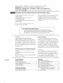
Before
you begin--Read
these instructions
completely
and carefully.
Save these instructions
for local inspector's
use.
IMPORTANT:
OBSERVE
ALL GOVERNING
CODES AND ORDINANCES.
NOTE TO INSTALLER: Be sure to leave these instructions
with the Consumer.
IMPORTANT:
NOTE TO CONSUMER:
Ir!,w.,l:mh, t_ This appliance
must
Kee t) these
be properly
instructions
grounded.
See "Electrical
For Monogram local service in your area,
1-800-444-1845.
For Monogram Service in Canada,
Call 1-888-880-3030.
For Monogram Parts and Accessories,
1-800-626-2002.
If you received
should contact
a damaged
cooktop,
your dealer.
with your
call
Proper
Owner's
Supply",
installation
Manual
page
for future
reference.
6. I
is the responsibility
of the
installer.
Product
failure due to improper
installation
is not covered
under the GE
Appliance
for details.
Warranty.
See the Owner's
Manual
you
In the Commonwealthof Massachusetts:
• This product must be installed by a licensed plumber or gas fitter
• When using ball type gas shut off valves, they shall be Thandle type
• A flexible gas connector, when used, must not exceed 3 feet
CAUTION:
THESE COOKTOPS SHOULD BE
INSTALLED IN CONJUNCTION
WITH A
SUITABLE OVERHEAD VENT HOOD. Due
Island
to the high heat capacity of this unit, particular attention
should be paid to the hood and
duct work installation
to assure it meets local
grounding
must comply with applicable
codes.
In the absence of local codes, the cooktop
should be installed
in accordance
with the
National
Fuel Gas Code ANSI 223.1-1990
and
National
Electrical
Code ANSI/NFPA
70-1990.
building
codes.
Standard
countertop
A 1200 CFM Hood
cooktops.
A 600 CFM hood
and island installations:
is recommended
for 48"
is recommended
cooktops.
Hoods should be 24" rain.
width as the cooktop.
Contents
deep
for 36"
and the same
installations:
Check local building
codes for the proper
method
of cooktop
installation.
Local codes
vary. Installation,
electrical
connections
and
CAUTION:
These cooktops are extremely hem% Due to
the weight and size of the cooktop and to
reduce the risk of personal injury or damage
to the product, TWO PEOPLE ARE
REQUIRED FOR PROPER INSTALLATION.
Installation
Step 1: Remove Packaging ........................................ 7
Step 2: Cut the Countertop Opening ........................ 7
Step 3: Install the Cooktop ......................................... 8
Installation Options ..................................................... 5 Step 4: Conect Cooktop to Gas ................................. 8
Advance Planning ....................................................... 5 Step 5: Install the Cooktop Backguard .................... 8
Step 6: Connect Electrical ......................................... 9
Step 7: Assemble Burners, Check Ignition ............. 9
Installation Preparation
Adjustable Low Burner Settings ................ 10
Tools & Materials Required.......................................
6
Finalize
Installation ................................................... 10
Power Supply Locations ............................................
6
Design Information
Models Available .........................................................
3
Accessory Requirements .......................................... 3
Product Dimensions and Clearances ...................... 4
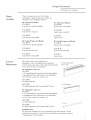
Design Information
Professional
Models
Available
These cooktops are factory set for either
natural gas or liquid propane gas. Order the
model for your installation situation.
48" Natural Gas Models:
ZGU48N4G
4 gas burners, grill and griddle
36" Natural
ZGU36N4D
4 gas burners
and
ZGU48N6R
6 gas burners
and grill
ZGU36N4R
4 gas burners
and grill
ZGU48N6D
6 gas burners
and griddle
ZGU36N6
6 gas burners
griddle
36" Liquid Propane Gas Models:
ZGU36L4D
4 gas burners,
4 gas burners
grill and griddle
and griddle
ZGU36L4R
6 gas burners
and grill
4 gas burners
ZGU48L6D
and grill
ZGU36L6
6 gas burners
Requirements
Gas Models:
48" Liquid Propane Gas Models:
ZGU48L4G
ZGU48L6R
Accessory
Gas Cooktops
and griddle
6 gas burners
All models require
the installation
of a
backguard
or trim. A backguard/trim
should be
ordered
at the same time as the cooktop.
Both should
be on site at the time of installation.
48" backguards,
ZXC1B48
order
22" HighBackguardWith
one:
1/2" trim backguard
(required
for island installations
or installations
where back wall is non-combustible;
such as brick, ceramic
tile, marble,
etc).
Wam_
ZXC12B48
12" high backguard
ZXC22B48
22" high backguard
36" backguards,
ZXC1B36
12" HighBackguard
with warming
order
shelf (2 piece)
one:
1/2" trim backguard
(required
for island installations
or installations
where back wall is non-combustible;
such as brick, ceramic
tile, marble,
etc).
ZXC12B36
12" high
backguard
ZXC22B36
22" high
backguard
Installation
For approved
with warming
shelf
(2 piece)
Note:
installations
to non-combustible
back wall materials,
material
representative
to ensure that the material
has appropriate
to staining and/or
discoloration.
consult
resistance
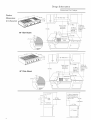
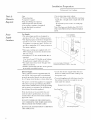
Design
Information
Professional
Gas Cooktops
Product
Dimensions
Cleai"ances
1M::!
3 ,,M,
18"Min.
48"
Wide
Instructions /
Combustible
t
Material From
Combusiible Cooking
Material
Surface
Models
7/8"
/o
36" Min. to
Combustible
Material From
Cooking
36"
Wide Models
1/2"
/o
/
_26-5/8_
2q/2"_u7
/
_Hiclh
/
21-11/4"
Si_elfo
I
36"Min.
Combustibles
2 _ow___
f
12"Min.to Combustibles
WithoutBackguard
or O"
to NonoCombustible
Wall
with1/2"Trim
36"Min.
Combustibles
_/
1/2"Trim
-- O"Clearance
to
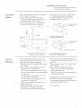
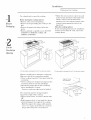
Installation
Preparation
P1"ofessiollal
Installation
These
24"
Options
cooktops
can
or deeper
• In 24"
25"
deep
cooktop
the
• In 25"
deep
flush
with
the
project
fi'ont
of the
approximately
fi'ont
of the
cabinets,
the
• The stainless surface of tile cooktop
will be
1/2" higher than adjacent
countertop.
• Cooktop
fits flush to rear of cutout,
no
in standard
cabinets.
cabinets,
will
beyond
be installed
1-7/8"
additional
suf)port
is required.
countertop.
the
fi'ont
Gas Cooktops
cooktop
of tile
will
be
Oooktop
1/2" AboveA@acent
Counte)tops.
countertop.
0
26-5/8"
21q/4"
High __
/ Back /
Countertop _
Low Back
FrontProjectsOutwardasShown
FromStandardDepthCabinets.
12"
Cooktop
8-7J16,,
Z lj2,,5
'
O
1
,_
3" to CenterLine_II
1/2" AboveAdjacent
Countertops,
ii
of GasInlet
/_,,_22-3/4"
1/2" _
23-1/4"
2-1/2'_I
CabinetFace-ProjectingControlPanel_
CabinetFace- FlushControlPanel_
Advance
Refer
to
"Dimensions
appropriate
Planning
ances
placement
when
can
hood
above
The
The
the
-For
vent
vent
the
hood
hood
necessary
clear-
installation.
be installed
the
for
installation
cooktop
directly
above
of a vent
surface.
should
should
be at least 24" deep.
be the same
width
as
cooktop.
48"
hood
For
the
not
cooktop.
recommend
Clearances"
and
planning
• Cabinetry
the
• We
and
models,
blower
36"
hood
• Refer
height
• Working
should
between
we recommend
be
models,
blower
we recommend
be
to hood
600
the
the
Allow 36" rain. above the cooking
combustible
materials.
vent
instructions
for
must conform
areas
adjacent
to the cooktop
have
18" minimum
clearance
and
cabinet
surface
to
bottom.
with local codes.
In the absence
of local codes, the gas
cooktop
must comply with the National
Gas Code, ANSI Z223.1-1990.
dimensions.
countertop
and side wall or
be at least 12" on
• These cooktops
require
8" free space below
the countertop.
• If the cooktop
is installed in an island:
-Allow 12" rain. clearance
at the back to
combustible
materials.
• Installation
CFM.
installation
• Clearance
between
cooktop
combustible
material
must
each side.
vent
CFM.
1200
FrontFlushWith Cabinets-a Minimum
of 25-3/4" CabinetDepthRequired
A.G.A. approved.
Fuel
Installation
Preparation
Professional
Tools 8,z
Materials
Required:
• Saw
• Measuring
• Carlaenter's
• Pipe
and
• Manual
• Gas
• Pipe
Po weF
Supply
Locations
square
fttings
gas
as required.
line
[aressure
• Large
• Gas-resistant
• 5 foot, 5/8"
supply line.
codes.)
tape
shut-off
regulator
flat-blade
Gas Cooktops
pipe joint sealant
AGA-certified
flexible
(Length
must comply
metal gas
with local
If required
by local codes, use solid pipe
fittings.
Note: Purchase
new flexible line. DO NOT
valve.
(SUlalalied)
screwdriver
USE OLD, PREVIOUSLY USED FLEXIBLE
LINE.
wrench
Gas Supply:
• The natural
gas models are designed
to
otaerate at 6" to 14" water column
taressure.
• Tim liquid faropane
models are designed
to
operate
at 11" to 14" water colmnn
faressure.
A regulator
is required
at the g.P. source to
provide a maxinmm
of 14" water faressure to
tim range regulator.
• These
gas cooktops
are supplied
with 1/2"
gas connection
located at tim
left rear corner.
• A nAnimum
5/8" dia. metal flexible line is
NPT female
required.
Use 5-foot long 5/8" flexible metal tubing.
(Length
must comfaly with local codes.)
• For rigid connection,
locate tim pipe stub
within area shown.
LocateGasSupply
ProtrusionFromWall or on Floor2" FromWall
• Install a manual
shut-off valve in tim gas line,
in an easily accessible
location.
Electric Supply:
These cooktops
must be SUlatalied with 120
volt, 60 Hz., and connected
to a individual,
faroperly grounded
by a 15 amp circuit
branch
breaker
• Locate
shown
foot power
circuit protected
or time delay fuse.
The faower cord of this appliance
is equipped
with a three-prong
(grounding)
plug which
mates with a standard
three-t)rong
grounding
wall recetatacle
to minimize
the possibility
of
shock hazard fl'om this appliance.
If the electrical
service
farovided
does
cord.
• To avoid tangling
cord with items stored in
the cabinet,
locate the recetatacle
on rear
wall, inside the cabinet.
ReceptacleBoxCover
ThreeProngPlug
not
meet the above specifications,
it is recommended
that a licensed electrician
install
afataroved
the electric supply within the area
or within reach of the cooktop's
six
an
outlet.
DO NOT UNDER ANY CIRCUMSTANCES,
CUT OR REMOVE THE THIRD (GROUND)
PRONG FROM THE POWER CORD.
DO NOT USE AN EXTENSION
THIS APPLIANCE.
CORD WITH
ThreeProngReceptacle
Installation
Pl"ofessional
Use a hand-truck
Remove
Packaging
to move
• Flatten the carton and use a piece as a pad
on the bottom
and back of the hand-truck.
this cooktop.
Before moving the cooktop
indoors:
• Remove outer carton and packing.
• Remove the straps holding
the cooktop
skid.
• Remove
knobs.
the grates
and
• Remove
grill and/or
drawers
griddle
below
covers.
Gas Cooktops
Lift the cooktop
onto the hand-truck
standing
on its end, with the bottom of the
cooktop
resting against the back of the
hand-tru ck.
to the
Move the cooktop
indoors:
If door and passageways
into the installation
location
are less than 30" wide, remove the
the
DO NOT
ATTEMPT TO REMOVE A GRILL OR
GRIDDLE ASSEMBLY.
cooktop
knobs.
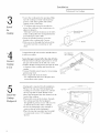
2
Cut the
Countertop
Opening
48" wide models are designedto fit in 48" or wider base cabinets
Measure
carefully when cutting the countertop.
Make sure sides of the opening
are parallel.
• These cooktops
requires
8" free space below
countertop.
• These Cooktops
are designed
to hang
36" wide models are designedto fit in 36" or wider base cabinets
the
AdjacentCabinet
fl'om the
countertop
fl'om its rear and side flanges.
• Smooth
any rough edges on the countertop
before installing
the cooktop.
Formica
countertop
edges nmst
The countertop
must
be strong
be finished.
enough
to
support
the weight of the cooktop.
• Support
cleats can be secured
to cabinet
CounterSunk
Screws
sides.
OR
• Build a support
deck or box inside the cabinet
which will support
tim weight of the cooktop.
-Build the support
box using a solid material,
cut a 5" x 5" square in the left rear corner
for
the gas inlet and power cord clearances.
Installation
P1"ofessiollal
3
• Lower tim cooktop
into tim opening.
Make
sure tim cooktop
is evenly seated and sut>
ported.
A side fl'ame gasket will seal tim
cooktop
to tim countertop.
• "L" brackets
with screws are provided
to
Msta]]
secure tim cooktop
to the countertop
or to
adjacent
cabinetry.
-Alternate
screw hole locations
on tile sides
the
Cooktop
Alternate Bracket
ScrewHoles
of tim cooktop
allow for varying thicknesses
of countertops
or side cleats.
• Select tim bracket location,
secure tim
bracket to tim cooktop
with 2 screws.
• Drive one screw through
tim bottom
of tim
"g" bracket and into countertop
or side
cleats.
A malrual shut-off valve must
it will be accessible.
Connect
Cooktop
to Gas
be installed
where
connections
A backguard
Cooktop
Backguard
Flexor RigidGas
LineToRegul_
in tim system.
is required
the cooktop
and into tile backguard.
(If a griddle
is present,
secure with 2 screws
on the left and center of the cooktop.)
• Secure the backguard
to the wall with 3
screws at the top of the backguard.
• Place the top cap in position
and re-install
screws.
,/_-f
for all installations.
• Insert the backguard
into the channel
on the
back of the cooktop.
• Fasten with screws at the bottom,
through
2 countersunk
shown.)
Regulator
and
• Remove the top cap of tile backguard
by
backing out 2 counter
sunk screws. Lift off
the top cap and set aside. Retain screws.
the
-"L" Bracket
Assure that gas is turned off at the shut-off valve.
• Lift and remove all open top burners
to reveal
tim gas inlet location
at tim left rear corner.
• Pull tim flexible metal gas line through
tim back
oi" bottom of tim cooktop
until it meets tim
regular.
• Connect
flexible metal connector
to incoming
gas line pipe stub.
• Turn on gas and check for leaks:
Use a liquid leak detector
at alljoints
Msta]]
Gas Cooktops
(12" backguard
TopCap_
2Screws_,
Installation
Professional
Plug power cord into properly
receptacle.
Gas Cooktops
grounded
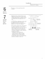
st< 6
Connect
Electrical
s,,
7
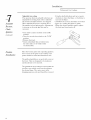
Assemble
BlJl_neYs,
Check
Ignition
• Replace the
• AdJustments
burner
should
vibration
during
gas supply make
sary.
bowls and burner
not be required,
transit
minor
or variations
adjustments
caps.
unless
in local
neces-
m
J
adjustments
• Burner
are made
flames
should
after
.Main Burner
Venturi(rear)
be blue
and
stable
{D
¢
niteri
i
installation.
urner
shutter
or burner
ports are not blocked.
If
one of these conditions
continues,
adjust the
air shutter
as required.
-If the flame is too yellow, there is
insufficient
air flow, adjust the shutter
counterclockwise
to increase
air inlet.
If the flame is noisy or tends to lift away
fl'om the burner,
there is too much air. Turn
the shutter
clockwise to reduce air.
u
ii
iii
Ul
Ul
- SimmerBurner
Venturi(rear)
i
with
no yellow or yellow tips, excessive noise or
lifting of the flame fl'om the burner.
If any of
these conditions
exist, check
that the air
flgniter
urner
CAUTION:
Burner adjustments
must be made
by a qualified
technician
at the time of
installation.
Extreme
care should be used if
m
- Air Shutter
MainBurner
Venturi(front)
"SimmerBurner
Venturi(front)
Installation
Professional
Adjustable
The
low
open
adjustable
BIJI_HeI_S,
Minor
and
and
in local
to increase
or decrease
Ignition
• Turn
knob
valves
valve
before
may
fluctuations
necessary.
grill
Each
adjusted
adjustments
Check
(conm_ll_t)
burners
low setting.
ally tested
Assemble
• Grip the shaft with pliers and turn counterclockwise
to lower the flame, or clockwise
to
increase
the flame.
CAUTION: Do not turn the flame so low that
setting
top
an
is individu-
it is shipped.
be required
due
gas pressure.
gas
have
it goes out, causing the igniter to spark.
• When the desired setting is made, replace
the knob and turn burner
off.
to
Adjustments
flow
counter-clockwise
may
be
to the
LITE
to the
"LOW"
position.
• Once
lit, turn
position.
• Remove
• Insert
the
the
the
know
knob.
a thin-blade
valve
back
shaft.
flat
(3/32"
screwdriver
blade
into
width
reconlmended.)
Finalize
Installation
Place the burner
grates into operating
position.
Press corner
of the grate to the cooktop.
The
grates
The
should
grill and
be seated
griddle
and
should
are secured
not rock.
with screws
at
the front. They are designed
to be stationary
and should not to be removed.
The griddle has two leveling screws beneath
rear flue cover which can be used to adjust
the desired slope. The center screw is for
shipping
10
purposes
only and should
Gas Cooktops
the
to
be removed.
Notes
Professional
Gas Cooktops
Note: While performing installations described in this book,
safety glasses or goggles should be worn.
Fur MonQqmm ioc+d ,service in your area, call
1-800-444-1845.
Note: P1oduct improvement
Genelal Electric. Thelefore,
specifications
are
subject
to
is a continuing
endeavor at
matelials, appearance
and
change
without
notice.
O
Monogram:
Webringgoodthingsto life.
GECortsumet PtocJucts
_No,49-8812-6
g
No, 164D3333P056 /
(N.D,760) 4/03
10659-Rev, 6
General Electric Company
Louisdlle, KY40225
© 2003 General Electric Company