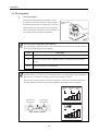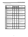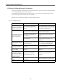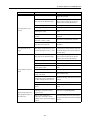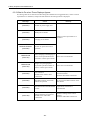
1
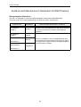
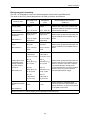
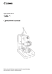
Digital Retinal Camera CR-1 Operation Manual Before using the instrument, be sure to read this manual thoroughly. Keep the manual where it is easily accessible. PLEASE NOTE 1. Please contact a Canon representative or distributor to have the instruments installed. 2. Computer, monitor, or other equipment used in the CR-1 fundus imaging system must be conforming to the IEC60601-1/UL60601-1 or IEC60950/UL60950. Furthermore all configurations shall comply with the system standard IEC 60601-1-1. If in doubt, consult the technical services department or your local representative. Be sure to also use an isolation transformer conforming to IEC60601-1/UL60601-1 when a computer or monitor conforming to IEC60950/UL60950 is used. 3. To maintain compliance to IEC60601-1-2, it is recommended that the computer, monitor, or other equipment configured with the CR-1 be evaluated to IEC60601-1-2 or FCC Part.15 Subpart B Class B and CISPR 24. 4. The user is responsible for the use and maintenance of the product. We suggest that a member of the user’s staff be designated as being in charge of maintenance so as to ensure that the product is kept in a safe and good condition. Also, medical products must be used only by a qualified person. 5. This product may malfunction due to electromagnetic waves caused by cellular phones, transceivers, radiocontrolled toys, etc. Be sure to avoid having objects such as these, which affect this product, brought near the product. 6. In no event will Canon be liable for direct or indirect consequential damage arising out of the use of this product. Canon will not be liable for loss of image data due to any reason. 7. Reading of image and storage of data must be performed in accordance with the law of the country where the product is being used. Also, the user is responsible for maintaining the privacy of image data. 8. The power cable supplied is designed to be used solely with this camera. Do not use it for any other products. 9. Canon reserves the right to change the specifications, configuration and appearance of the product without prior notice. European Union (and EEA*) only. This symbol indicates that this product is not to be disposed of with your household waste, according to the WEEE Directive (2002/96/EC) and your national law. This product should be handed over to a designated collection point, e.g., on an authorized one-for-one basis when you buy a new similar product or to an authorized collection site for recycling waste electrical and electronic equipment (EEE). Improper handling of this type of waste could have a possible negative impact on the environment and human health due to potentially hazardous substances that are generally associated with EEE. At the same time, your cooperation in the correct disposal of this product will contribute to the effective usage of natural resources. For more information about where you can drop off your waste equipment for recycling, please contact your local city office, waste authority, approved WEEE scheme or your household waste disposal service. For more information regarding return and recycling of WEEE products, please visit www.canon-europe.com. * EEA : Norway, Iceland and Liechtenstein © CANON INC. 2008 All rights reserved. Under copyright laws, this manual may not be copied, in whole or in part, without the written consent of Canon. Safety Information Regulations This instrument conforms to IEC 60601-1-2:2001. For U.S.A. and Canada • When the CR-1 is going to be operated at a voltage of 240V in USA or Canada, be sure to connect the instrument to a center tapped voltage source. • This instrument is a CLASS I EQUIPMENT according to UL60601-1. MEDICAL EQUIPMENT WITH RESPECT TO ELETRICAL SHOCK, FIRE AND MECHANICAL HAZARDS ONLY IN ACCORDANCE WITH UL60601-1 <CONTROL NUMBER 41C4> WITH RESPECT TO ELETRIC SHOCK, FIRE MECHANICAL AND OTHER SPECIFIED HAZARDS ONLY IN ACCORDANCE WITH CAN/CSA C22.2 NO. 601.1, MEDICAL EQUIPMENT CERTIFIED FOR CANADA • Grounding reliability can only be achieved when the equipment is connected to an equivalent receptacle marked “Hospital Only” or “Hospital Grade”. • The following mark indicates that the instrument is a Type B Applied Parts. • The degree of protection against ingress of water is IPX0. • This equipment is not suitable for use in the presence of a flammable anaesthetic mixture with air or with oxygen or nitrous oxide. • The mode of operation is Continuous Operation. For EU Countries • The following mark shows compliance of the instrument with Directive 93/42/EEC. • This instrument is a CLASS I EQUIPMENT according to EN 60601-1. • The following mark indicates that the instrument is a Type B Applied Parts according to EN 60601-1. Für Deutschland • Während des Betriebs liegt der Schalldruckpegel dieses Instruments bei 70 dB(A) oder weniger gemäß ISO 7779. (1) Safety Information Guidance and Manufacturer’s Declaration for EMC Directive Electromagnetic Emissions The CR-1 is intended for use in the electromagnetic environment specified below. The user of the CR-1 should assure that it is used in such an environment. Emission Test Compliance RF emissions CISPR 11 GROUP 1 RF emissions CISPR 11 Class B Harmonic emissions Class A IEC 61000-3-2 Voltage fluctuations/ flicker emissions Electromagnetic Environment – Guidance The CR-1 uses RF energy only for its internal function. Therefore, its RF emissions are very low and are not likely to cause any interference in nearby electromagnetic equipment. The CR-1 is suitable for use in all establishments other than domestic and those directly connected to the public low-voltage power supply network that supplies buildings used for domestic purposes. Compliances IEC 61000-3-3 (2) Safety Information Electromagnetic Immunity The CR-1 is intended for use in the electromagnetic environment specified below. The user of the CR-1 should assure that it is used in such an environment. Immunity Test IEC 60601 Test Level Compliance Level Electrostatic discharge (ESD) ±(2, 4, 6) kV contact ±(2, 4, 6) kV contact IEC 61000-4-2 ±(2, 4, 8) kV air ±(2, 4, 8) kV air ±2 kV for power supply lines ±2 kV for power supply lines ±1 kV for input/ output lines ±1 kV for input/ output lines ±1 kV differential mode ±1 kV differential mode ±2 kV common mode ±2 kV common mode <5% UT (>95% dip in UT) for 0.5 cycle <5% UT (>95% dip in UT) for 0.5 cycle 40% UT (60% dip in UT) for 5 cycles 40% UT (60% dip in UT) for 5 cycles 70% UT (30% dip in UT) for 25 cycles 70% UT (30% dip in UT) for 25 cycles <5% UT (>95% dip in UT) for 5 sec <5% UT (>95% dip in UT) for 5 sec Electrical fast transient/burst IEC 61000-4-4 Surge IEC 61000-4-5 Voltage dips, short interruptions and voltage variations on power supply input lines IEC 61000-4-11 Power frequency (50/60Hz) magnetic field 3 A/m Electromagnetic Environment – Guidance Floors should be wood, concrete or ceramic tile. If floors are covered with synthetic material, the relative humidity should be at least 30%. Mains power quality should be that of a typical commercial or hospital environment. Mains power quality should be that of a typical commercial or hospital environment. Mains power quality should be that of a typical commercial or hospital environment. If the user of the CR-1 requires continued operation during power mains interruptions, it is recommended that the CR-1 be powered from an uninterruptible power supply. Power frequency magnetic fields should be at levels characteristic of a typical location in a typical commercial or hospital environment. 3 A/m IEC 61000-4-8 NOTE: UT is the a.c. mains voltage prior to application of the test level. (3) Safety Information Immunity Test IEC 60601 Test Level Compliance Level Electromagnetic Environment – Guidance Portable and mobile RF communications equipment should be used no closer to any part of the CR-1, including cables, than the recommended separation distance calculated from the equation applicable to the frequency of the transmitter. Recommended separations distance d = 1.2 P Conducted RF IEC 61000-4-6 Radiated RF IEC 61000-4-3 3 Vrms 150 kHz to 80 MHz 3 V/m 80 MHz to 2.5 GHz d = 1.2 P 80 MHz to 800 MHz 3 Vrms d = 2.3 P 800 MHz to 2.5 GHz where P is the maximum output power rating of the transmitter in watts (W) according to the transmitter manufacturer and d is the recommended separation distance in metres (m). 3 V/m Field strengths from fixed RF transmitters, as determined by an electromagnetic site surveya, should be less than the compliance level in each frequency rangeb. Interference may occur in the vicinity of equipment marked with the following symbol: NOTE 1: At 80 MHz and 800 MHz, the higher frequency range applies. NOTE 2: These guidelines may not apply in all situations. Electromagnetic propagation is affected by absorption and reflections from structures, object and people. a Field strengths from fixed transmitters, such as base stations for radio (cellular/cordless) telephones and land mobile radios, amateur radio, AM and FM radio broadcast and TV broadcast cannot be predicted theoretically with accuracy. To assess the electromagnetic environment due to fixed RF transmitters, an electromagnetic site survey should be considered. If the measured field strength in the location where the CR-1 is used exceeds the applicable RF compliance level above, the CR-1 should be observed to verify normal operation. If abnormal performance is observed, additional measures may be necessary, such as reorienting or relocating the CR-1. b Over the frequency range 150 kHz to 80 MHz, field strengths should be less than 3 V/m. (4) Safety Information Recommended Separation Distances The CR-1 is intended for use in an electromagnetic environment in which radiated RF disturbances are controlled. The user of the CR-1 can help prevent electromagnetic interference by maintaining a minimum distance between portable and mobile RF communications equipment (transmitters) and the CR-1 as recommended below, according to the maximum output power of the communications equipment. Rated maximum output power of transmitter Separation distance according to frequency of transmitter m 150 kHz ~ 80 MHz 80 MHz ~ 800 MHz 800 MHz ~ 2.5 GHz W d = 1.2 P d = 1.2 P d = 2.3 P 0.01 0.12 0.12 0.23 0.1 0.38 0.38 0.73 1 1.2 1.2 2.3 10 3.8 3.8 7.3 100 12 12 23 For transmitters rated at a maximum output power not listed above, the recommended separation distance d in metres (m) can be estimated using the equation applicable to the frequency of the transmitter, where P is the maximum output power rating of the transmitter in watts (W) according to the transmitter manufacturer. NOTE 1: At 80 MHz and 800 MHz, the separation distance for the higher frequency range applies. NOTE 2: These guidelines may not apply in all situations. Electromagnetic propagation is affected by absorption and reflection from structures, objects and people. (5) Safety Information General Safety Information Follow the safety instructions in this manual and all warnings and cautions printed on the warning labels. Ignoring such cautions or warnings while handling the product may result in injury or accident. Be sure to read and fully understand the manual before using this product. Keep this manual for future reference. Meaning of Caution Signs ! WARNING This indicates a potentially hazardous situation which, if not heeded, could result in death or serious injury to you or others. ! CAUTION This indicates hazardous situation which, if not heeded, may result in minor or moderate injury to you or others, or may result in machine damage. NOTE This is used to emphasize essential information. Be sure to read this information to avoid incorrect operation. (6) Safety Information Installation and Environment of Use ! WARNING Do not use or store the instrument near any flammable chemicals such as alcohol, thinner, benzine, etc. If chemicals are spilled or evaporate, it may result in fire or electric shock through contact with electric parts inside the instruments. Also, some disinfectants are flammable. Be sure to take care when using them. ! CAUTION Do not use or store the instrument in a location with the conditions listed below. Otherwise, it may result in failure or malfunction, fall or cause fire or injury. • Close to facilities where water is used. • Where it will be exposed to direct sunlight. • Close to air-conditioner or ventilation equipment. • Close to heat source such as a heater. • Prone to vibration. • Insecure place. • Dusty environment. • Saline or sulfurous environment. • High temperature or humidity. • Freezing or condensation. ! CAUTION Do not cover the vent holes on the cover. Otherwise, the temperature in the instrument may rise and cause fire. ! CAUTION Place the instrument on a firm table. Do not place it extremely near the edge of the table in order to avoid damage or injury due to falling. Installation Operation ! WARNING Do not connect the instrument with anything other than specified. Otherwise, it may result in fire or electric shock. Also, when other equipment is going to be connected to the instrument using the connector for interface, be sure to check after the connection that leakage current is within the tolerable value. For details, please contact a Canon representative or distributor. Power Supply ! WARNING Only operate the instrument with the type of power supply indicated on the rating label. Otherwise, it may result in fire or electric shock. ! WARNING Be sure to turn OFF the power before plugging or unplugging the cables as indicated in this manual. Also, do not handle it with wet hands. Otherwise, you may get an electric shock that may result in death or serious injury. ! WARNING Securely plug in the power cable into the AC outlet. If contact failure occurs, or if dust or metal object comes in contact with the exposed metal prong of the plug, fire or electric shock may result. (7) Safety Information Power Supply ! WARNING Be sure to hold the plug to disconnect the power cable. If you pull the cable, the core wire may be damaged, resulting in fire or electric shock. ! WARNING Do not cut or process the cables. Also, do not place anything heavy, including the instrument on it, step on it, pull it, bend it, or bundle it. Otherwise, the cable may be damaged, which may result in fire or electric shock. ! WARNING Do not get the power for more than one instrument from the same AC outlet. Otherwise, it may result in fire or electric shock. ! CAUTION Before connecting or disconnecting the cables, be sure to hold the instrument firmly in order to ensure safety. Otherwise, the main unit may fall over, possibly causing injury. ! CAUTION The instrument is shipped with a grounding type (three-core) power cable. To reduce the risk of electric shock, always plug the cable into a grounded power outlet. ! CAUTION To make it easy to disconnect the plug at any time, avoid putting any obstacles near the outlet. Handling ! WARNING Never disassemble or modify the product as it may result in fire or electric shock. Also, since the instrument incorporates high-voltage parts that may cause electric shocks and other hazardous parts, touching them may cause death or serious injury. ! WARNING Do not place anything on top of the instrument. Otherwise, the object may fall and cause injury. Also, if metal objects such as needle or clip falls into the instrument, or if liquid is spilled, it may result in fire or electric shock. ! WARNING When the instrument is going to be moved, be sure to turn OFF the power, unplug the power cable from the AC outlet, and disconnect other cables. Otherwise, the cable may be damaged, which may result in fire or electric shock. Also, when the instrument is going to be carried, be sure to tighten the stage unit lock button, grip the lift handles at the left and right of the bottom panel and hold it horizontally. Do not hold it by the digital camera (sold separately) or the face rest poles or other parts, as they may come off and result in injury. ! WARNING Do not hit or drop the instrument. The instrument may be damaged if it receives a strong jolt, which may result in fire or electric shock if the instrument is used without it being repaired. ! CAUTION Wipe the forehead rest and chin rest with ethanol or glutaraldehyde solution to disinfect them each time a different patient uses the instrument in order to prevent infection. Please consult a specialist for the procedure for disinfection. (8) Safety Information Handling ! CAUTION To ensure cleanliness, replace the chin rest paper whenever changing patients. ! CAUTION When adjusting the forward position of the main unit, be sure to move the main unit slowly toward the patient while looking from the side of the patient, so as to prevent accidental contact of the objective lens with patient. ! CAUTION Do not place your hand or fingers between the stage and base. Also, ensure that the patient does not place his/her hand or fingers there either. Otherwise, fingers may be hurt. ! CAUTION When the instrument is not going to be used, turn OFF the power. Also, unplug the power cable from the AC outlet when it is not going to be used for a long time. When Problem Occurs ! WARNING Should any of the following occur, immediately turn OFF the power of each instrument, unplug the power cable from the AC outlet, and contact a Canon representative or distributor. • When there is smoke, odd smell or abnormal sound. • When liquid has been spilled into the instrument or a metal object has entered through an opening. • When the instrument has been dropped and it is damaged. Maintenance and Inspection ! WARNING For safety reasons, be sure to turn OFF the power when the inspections indicated in this manual are going to be performed. Otherwise, it may result in electric shock. ! WARNING When the instrument is going to be cleaned, be sure to turn OFF the power, and unplug the power cable from the AC outlet. Never use alcohol, benzine, thinner or any other flammable cleaning agents. Otherwise, fire or electric shock may result. ! WARNING Clean the plug of the power cable periodically by unplugging it from the AC outlet and removing dust or dirt from the plug, its periphery and AC outlet with a dry cloth. If the cable is kept plugged in for a long time in a dusty, humid or sooty place, dust around the plug will attract moisture, and this could cause insulation failure which could result in a fire. ! WARNING The instrument must be repaired by a qualified engineer only. If it is not repaired properly, it may cause fire, electric shock, or accident. ! CAUTION For safety reasons, be sure to inspect the instrument before using it. (9) Safety Information Labels and Markings on the Instrument The CR-1 has a label on it. The label contents and its position are indicated below. (10) Contents Safety Information..........................................................................................(1) Regulations ............................................................................................(1) Guidance and Manufacturer’s Declaration for EMC Directive ...............(2) General Safety Information ....................................................................(6) Labels and Markings on the Instrument ..............................................(10) 1. Features...................................................................................................... 1 2. Notes for Using the Instrument ................................................................... 2 3. Description .................................................................................................. 4 3.1 Main Unit ........................................................................................... 4 3.2 Operation Panel ................................................................................. 6 3.3 Monitor Display Screens .................................................................... 7 4. Operation .................................................................................................... 9 4.1 Preparation ........................................................................................ 9 4.2 Adjusting the Position and Focusing ............................................... 11 4.3 Photography .................................................................................... 18 5. Settings ..................................................................................................... 21 6. Daily Inspection and Maintenance ............................................................ 23 6.1 Inspection ........................................................................................ 23 6.1.1 Before Turning ON the Power ............................................... 23 6.1.2 Turning ON the Power ........................................................... 25 6.2 Before Calling a Service Technician ................................................ 26 6.2.1 Troubleshooting ..................................................................... 26 6.2.2 What to Do when These Displays Appear ............................. 28 6.3 Cleaning and Disinfection ................................................................ 29 6.3.1 Objective Lens ....................................................................... 29 6.3.2 Forehead Rest ....................................................................... 30 6.3.3 Cover and Monitor ................................................................. 30 6.4 Refilling the Chin Rest Paper .......................................................... 31 6.5 Power Cable Connections ............................................................... 32 Contents 6.6 Attaching and Removing the EOS Digital Camera .......................... 33 6.6.1 Attaching the EOS Digital Camera ........................................ 33 6.6.2 Removing the EOS Digital Camera ....................................... 34 6.7 Connecting the USB Cable .............................................................. 36 6.8 Carrying the Instrument ................................................................... 37 7. Service Information ................................................................................... 39 8. Main Specifications ................................................................................... 40 9. Components.............................................................................................. 41 1. Features The Canon CR-1 digital retinal camera is used to take digital photographic retinal images of patient’s eyes across a wide range (photographic angle of view of 45 degrees) in a naturally dilated state without the use of mydriatics. It has the following features. Compact size and superior operability Compact dimensions and a light weight. Since the main unit can be raised and lowered by the operation lever, and the chin rest became motordriven, the alignment procedure has dramatically improved. Function for photographing small pupils supported The camera can photograph small pupils when their field angle is 45° and the diameter is ø4 mm or more. If it is hard to dilate the pupil of a patient’s eye, the small pupil photography function enables photographs to be taken of pupils with a diameter of ø3.7 mm or more. Optimum system for digital photography By using the Retinal imaging control software NM system that is optimized for digital photography (hereinafter called “control software”), the images photographed by the CR-1 can be browsed, processed, stored, output to the DICOM storage server, exported to DICOM files and output to an inkjet printer. High-speed image transfer is enabled using the USB 2.0 interface. In addition, depending on the photograph condition, flash intensity and EOS digital camera are automatically set and other steps are taken so as to optimize the photography work flow. High-picture-quality, high-definition diagnostic images Diagnostic images with a high picture quality and high definition can be obtained by using an EOS digital camera which incorporates a large, high-definition CMOS sensor. -1- 2. Notes for Using the Instrument Before Use • Check and clean the objective lens before taking an image, as any stains or scratches on it will appear as white spots. • Sudden heating of the room in cold areas will cause condensation to form on the objective lens or on optical parts inside the instrument. In this case, wait until condensation disappears before performing photography. • Do not touch the lens part of the main unit and the mirror part of the digital camera when attaching and detaching the digital camera from the main unit. If any dirt, fingerprints, dust, and other foreign objects attaches to the lens or mirror part, you cannot take a good image. When Images are Taken • Do not use the digital camera’s built-in flash. After Use • Turn OFF the power of the instrument. Place the cap over the objective lens, and place the dust cover over the instrument. You cannot take a good picture when the objective lens is dirty. • If the EOS digital camera is removed and left unattached, dust and other foreign objects can enter the main unit and the EOS digital camera. Be sure to always attach the caps to the respective mounts. Cleaning and disinfection • Do not let the tip of a blower touch the objective lens. • Do not wipe off or rub the objective lens when there is dust or other substances on it. This could scratch the lens surface. • Never wipe the objective lens with disinfecting ethanol, eyeglass lens cleaner, or cleaning paper containing silicon. The lens surface could be damaged or the surface may not be completely wiped off. • Do not clean the cover of the instrument with lens cleaner. The cover of the instrument could be damaged. • Never use alcohol, benzine, thinner, or other solvents to clean the cover of the instrument. This could • Never use disinfecting ethanol, glutaraldehyde or other solvents to clean the cover of the instrument, damage the cover of the instrument. except the forehead rest and the chin rest. This could damage the cover of the instrument. • If the chin rest paper will not be used, be sure to disinfect the chin rest whenever the patient is changed in the same way as the forehead rest. -2- 2. Notes for Using the Instrument Environment of Use • Do not install or store the camera or leave it standing in an adverse environment such as where the temperature and humidity levels are high. Doing so may cause trouble and/or malfunction. Be sure to observe the points on page (7) when selecting the installation location. • Dust in the air will not only attach to the objective lens, but will also attach onto the optical parts inside the instrument. You cannot take a good image when dust is on them. Please keep the room clean. Installation • Please ask a Canon representative or distributor to perform installation of this product. • Please handle this product carefully. The adjustment can be altered if it is subjected to a strong shock or jolt. • If this product will be transported in an automobile or shipped a long distance, protective measures need to be taken for vibrations and shocks. Ask a Canon representative or distributor for more information. Others For U.S.A. Rx only-Caution: Federal law restricts this device to sale by or on the order of a licensed practitioner. Intended Use: CR-1 is intended to be used for taking digital images of retina of human eye without a mydriatic. For European Union Intended Use: This medical device is intended to observe image and record retinal fundus through the pupil without contact with subject’s eye for the purpose of diagnosis by way of producing fundus image information. -3- 3. Description 3.1 Main Unit f a b c g h i d j e Symbol k Name Function a Diopter compensation lever Used when the target is not brought into focus by turning the focus knob. b Height adjustment mark Adjust so that the height of the patient’s eye is aligned with this mark. This is used for adjusting the height of the chin rest. c Focus knob Used for focusing on patient’s eye. d Panel lighting Illuminates the operation panel (see page 6) area. e Lift handles To carry the camera, hold these parts at the left and right of the main unit’s bottom panel. f LCD monitor Displays the anterior eye and retina observation screens as well as various setting screen. g Digital Camera Take fundus images (sold separately) h Digital camera cover Covers the terminal of the digital camera. i Shutter release button Press this button to take an image. j Operation lever Aligns the camera with the patient’s eye. k Operation panel 3.2 Operation Panel (see page 6) -4- 3. Description l q r m s n o p t Symbol Name Function l External eye fixation unit terminal Accepts the external eye fixation unit (sold separately). m Objective lens Lens used for photography. n Stage unit lock button Locks and unlocks the stage unit. o Power switch The power turns ON when pressed to the I side, and the power turns OFF when pressed to the O side. p AC power connector The supplied power cable is connected. q Forehead rest Place the patient’s forehead against this rest. r Face rest Holds the patient’s face in place. s Chin rest Place the patient’s chin on this rest. t USB connector The USB cable is connected. -5- 3. Description 3.2 Operation Panel a f b g c h d e i Symbol Name Function a Brightness adjuster Used for adjusting brightness in field of view for observation. b ×2 switch Switches the ×2 photography function ON and OFF. c SP (Small pupil photography) switch Switches the function for photographing small pupil diameters ON and OFF. d Flash intensity switch Pressing the left switch reduces the flash intensity. Pressing the right switch increases the flash intensity. e ALIGNMENT switch Switches between the anterior eye observation screen and retina observation screen. f FIX TARGET switches Used to move the internal eye fixation lamp during retina observation. g SET switch Used to display the setup menu screen (see page 21), perform the blinking display and reference position operations of the internal eye fixation lamp. h CHIN REST switch Pressing the Pressing the i POWER lamp Lights up when the power is ON. It blinks in the sleep mode. -6- button raises the chin rest. button lowers the chin rest. 3. Description 3.3 Monitor Display Screens R a b g R h c i d j LOW e STEREO Anterior eye observation screen Symbol f STEREO Retina observation screen Name Function a Photographic status The photographic preparation status (see page 18) is indicated by colors. b ×2 photography Appears when the ×2 photography function is ON. c SP Appears when the small pupil photography function is ON. d Flash intensity mode “LOW” is displayed under low flash intensity conditions. e Flash intensity indicator Shows the flash intensity which has been selected. f Stereo mode Appears when the stereo mode (see page 14) has been set. g Left/right eye Either R (right eye) or L (left eye) is displayed. h SP range Indicates the small pupil photography range. i ×2 photography range Indicates the ×2 photography range. j Eye fixation lamp position The presentation position of the internal eye fixation lamp is shown here. -7- 3. Description -8- 4. Operation Concerning the power-saving function The power-saving function is activated under the following circumstances. • When none of the switches on the operation panel has been operated, when the stage unit has not been switched to the left or right or when the diopter correction slider has not been operated for 10 or more minutes while power is supplied to the camera When the power-saving function has been activated, the POWER lamp on the operation panel blinks. To restore normal operation, press any switch on the operation panel, move the stage to the left or right or operate the diopter compensation lever. Concerning control software operations For details on the control software operations, refer to the operation manual of the control software. Note: Before preparing to take photographs, check the sections on the Power Cable Connections (see page 32), Attaching the EOS Digital Camera (see page 33) and Connecting the USB Cable (see page 36). 4.1 Preparation 1 Turn ON the computer. Turn ON the computer, and start the control software. 2 Turn ON the power of the main unit. Press the power switch to the I side. The anterior eye observation screen is displayed on the LCD monitor. R Continued on the following page >> -9- 4. Operation 3 Unlock the stage unit. Press the stage unit lock button to release the lock. 4 Adjust the height of the main unit. Turn the operation lever, and align the main unit with the center position of the height adjustment mark. Center of height adjustment mark 5 Darken the room. Darken the room so that there is barely enough light (approx. 5 lux) by which to read a newspaper. 6 Input the study information into the computer. Use the control software to input the study information. 7 Disinfect the face rest, and replace the chin rest paper. ! CAUTION To prevent the risk of infection, wipe the forehead rest with a disinfectant such as ethanol or glutaraldehyde whenever the patient is changed. For details on the disinfection procedure, consult a specialist. To ensure cleanliness, replace the chin rest paper whenever the patient is ! CAUTION changed. If the chin rest papers will not be used, disinfect the chin rest as well. -10- 4. Operation 4.2 Adjusting the Position and Focusing 1 Have the patient sit down. Have the patient place his or her chin against the chin rest and his or her forehead against the forehead rest. 2 Align the height of the patient’s eye. Move the chin rest up or down so that the patient’s eye is aligned with the height adjustment mark by operating the CHIN REST switches. Height adjustment mark 3 Display the patient’s eye to be photographed on the monitor. Hold the operation lever, pull it towards you, and then move it in the direction of the eye to be photographed. Continued on the following page >> -11- 4. Operation 4 Align the position of the pupil. ! CAUTION When adjusting the position of the main unit in the front-back direction, slowly bring the main unit closer to the patient while looking at the patient’s eye from the side. You may injure the patient’s eye if the objective lens makes contact with it. ! CAUTION Do not put your fingers or hands between the sliding part and base of the stage unit . Similarly, do not allow patients to put their hands in these places. Otherwise, your or their hands or fingers may be pinched, possibly resulting in injury. (1) Use the operation lever to adjust the anterior eye image so that it is displayed more or less in the center of the monitor. If the image cannot be adjusted in the up/down direction, use the CHIN REST switch to move the patient’s face up or down. Direction Operation Height Turn the operation lever. Slide movement Hold the operation lever, and pull it to the left and right to perform rough adjustment, and tilt it to the left and right to perform fine adjustment. Forward/backward Hold the operation lever, and pull it forward and backward to perform rough adjustment, and tilt it forward and backward to perform fine adjustment. (2) Have the patient stare at the flashing eye fixation lamp (green). Note: When observing the anterior eye, it may not be possible for a patient requiring high diopter correction to see the eye fixation lamp. (3) Tilt the operation lever forward or backward so that the images of the pupil which have been split into the top and bottom are aligned. For coarse movements in the front/ back direction, move the stage unit back or forth while holding the operation lever. If the pupil is smaller than the inside pupil position alignment mark: Darken the room further to dilate the pupil more. If the pupil still does not become larger, use the SP function (see page 13). -12- 4. Operation Concerning the SP function Use the SP (small pupil photography) function if the pupil of the patient’s eye fails to become larger than the inside pupil position alignment mark even after waiting for a while in the darkened room. This function enables pupils with a diameter down to 3.7 mm to be photographed. (1) Press the SP switch on the operation panel. (2) Press the ALIGNMENT switch, and display the retinal image on the monitor. The photography range is now R displayed. SP range (3) From this point, operate by following the regular procedure. Note: Do not use the SP function when the patient’s eyes have been thoroughly dilated. The images will be overexposed. Note: The images may contain flare around the edges of the images outside the photography range. Continued on the following page >> -13- 4. Operation 5 Display the retina observation screen. Press the ALIGNMENT switch. The internal eye fixation lamp flashes for 3 seconds. R Note: When the stage unit is slid toward the other eye on the retina observation screen, the anterior eye observation screen is displayed. Concerning the stereo mode The stereo mode can be set to ON or OFF using the [Set menu] .Refer to 5. Settings (see page 21). When this mode is ON, “STEREO” is displayed on the observation screen. In the stereo mode, the display will not return to the anterior eye observation screen even when photographs are taken. 6 Adjust the brightness. Turning the brightness adjuster clockwise increases the brightness; conversely, turning it counterclockwise reduces the brightness. Concerning the brightness for observation There are four observation brightness positions on the scale. Considering the strain on the patient’s eye, select the lowest possible brightness level. 7 Have the patient place his or her face securely against the face rest and chin rest. -14- 4. Operation 8 Decide on the area to be photographed. Have the patient stare at the green internal eye fixation lamp. If necessary, while viewing the monitor, press the FIX TARGET switch to move the internal eye fixation lamp, and guide the patient’s eye. The internal eye fixation lamp moves up and down and toward the left and right. Resetting the internal eye fixation lamp position When the SET switch is held down for about 2 or more seconds, the internal eye fixation lamp flashes for 2 seconds and can be returned to its reference position. If flare is visible or the working distance dots cannot be seen If either of these events occurs, refer to 6.2.1 Troubleshooting (see page 26). 9 Select the photography range. Each time the ×2 switch is pressed, the x2 photography function is set from ON to OFF (or vice versa), and when the function is set to ON, “×2” is displayed on the monitor screen. When images are taken in this status, a range equivalent to one-fourth of the observation screen at the center (×2 photography range) is stored. The stored images will be enlarged and displayed on the monitor by the control software. Field angle is equivalent to 43°. R 2 photography range Continued on the following page >> -15- 4. Operation 10 Bring the eye into focus. Turn the focus knob and align the split lines into a single straight line. Split lines Working distance dots In the event of the following: When the split lines are not visible: If this is the case, refer to 6.2.1 Troubleshooting (see page 26). When the split lines are not aligned into a single straight line: If the split lines are not aligned: Use the diopter compensation lever to insert the diopter compensation lens, and take the photographs. Given below is the diopter range in which images can be photographed. 0 position: –10 to +15 D – position: –31 to –7 (D) + position: +11 to +33 (D) However, when the diopter compensation lever is aligned with the “–” or “+” position, the split lines will vanish from the screen so turn the focus knob and bring the examinee's eye into focus so that the retinal image is clearly visible. -16- Diopter compensation lever 4. Operation Note: When operating the diopter compensation lever, set it precisely to the 0, “–” or “+” position. If the lever is set to a position midway between two settings, fundus images will not be taken properly. 11 Adjust the position of the retinal image. Tilt the operation lever forward or backward so that the left and right working distance dots are made as small as possible. Also, use the operation lever to make fine adjustments so that the positions of these dots are symmetrical between the top and bottom and symmetrical between the left and right. Note: Flare will be visible around the edges of the retinal photographs unless these fine adjustments are undertaken properly. -17- 4. Operation 4.3 Photography 1 Take a photograph. Check that the photography status display is green. In a flare-free status, check the focus again, and press Shutter release button the shutter release button. A retinal image is now taken, and the anterior eye observation screen is displayed. However, the retina observation screen will remain on the monitor if the stereo mode is established. Concerning the photography status displays The photography preparation statuses of the retinal camera are indicated on the LCD monitor by the colors of the photography status displays. Color Green Description Images can be taken. Red In this status, preparations to take photographs are underway (photographs cannot be taken yet). This remains lighted at all times on the anterior eye observation screen. None Communications are not established with the control software (the retina observation status is not established). Concerning the adjustment of the flash intensity The flash intensity is already set to the standard level for each photography mode (standard/low flash intensity). To adjust the intensity, press the flash intensity switches. Each time one of these switches is pressed, the intensity is increased or reduced by steps of 0.3. The flash intensity selected is shown by the lighted area of the flash intensity indicator. Minimum value Decreases the flash intensity Increases the flash intensity Standard Maximum value value Standard photography Flash intensity switches Low flash intensity photography (LOW) -18- 4. Operation 2 Review the image. The fundus images and study information are displayed in the control software. Check the images. When the images taken are not clear If this is the case, refer to 6.2.1 Troubleshooting (see page 26). 3 Now take a photography of the other eye. Taking photographs of one eye will cause the pupils of both eyes to contract excessively. Wait at least 5 minutes, and check that the pupils have dilated. Then align the position of the other eye and bring it into focus by following the same steps as in section 4.2 (see page 11), and take the photographs. 4 End the study. End the study with the control software. 5 Lock the stage unit. Press the stage unit lock button to lock the stage unit. 6 Turn OFF the power of the main unit. Press the power switch to the O side. -19- 4. Operation -20- 5. Settings The various settings can be established on the setup menu screen. 1 Display the setup menu screen. Press the SET switch on the anterior eye observation screen. The setup menu screen is now displayed. SET MENU >MONITOR PANEL STEREO FIX RESET LOW FLASH SPLIT 50 4 ON . OFF ON . OFF ON . OFF ON . OFF SET END 2 Change the settings. Press the or FIX TARGET switch to select the items. Press the or FIX TARGET switch to select (or change) the setting. Selection item MONITOR PANEL Function Used to adjust the brightness of the monitor display screen. Any value from 1 to 100 can be set. Used to adjust the brightness of the panel lighting. Any value from 1 to 8 can be set. STEREO Used to set the stereo mode to ON or OFF. ON: The stereo mode is established. (The display does not return to the anterior eye observation screen after photographs are taken.) OFF: The stereo mode is not established. FIX RESET Used to select whether the internal eye fixation lamp is to be returned automatically to its reference position after photographs are taken. ON: The internal eye fixation lamp is returned automatically to its reference position after photographs are taken. OFF: The position of the internal eye fixation lamp remains unchanged even after photographs are taken. This setting cannot be used when the stereo mode is ON. Continued on the following page >> -21- 5. Settings Selection item LOW FLASH Used to select whether to take photographs at low flash intensity levels. ON: Photographs are taken at low flash intensity levels. OFF: Photographs are not taken at low flash intensity levels. SPLIT Used to select whether to display the split lines for focusing. ON: The split lines are displayed. (They are not displayed when diopter correction has been undertaken.) OFF: The split lines are not displayed. INT FIXATION 3 Function Used to select whether to use the internal eye fixation lamp. ON: The internal eye fixation lamp is used. OFF: The internal eye fixation lamp is not used. Exit the setup menu screen. When all of the settings have been performed, press the SET switch. The settings are saved, and the display returns to the anterior eye observation screen. If the main unit enters the sleep mode when the monitor displays the setup menu. If the main unit enters the sleep mode when the monitor displays the setup menu, it saves the last displayed settings immediately before entering the sleep mode. -22- 6. Daily Inspection and Maintenance ! WARNING The instrument must be repaired by a qualified engineer only. If it is not repaired properly, it may cause fire, electric shock, or accident. ! CAUTION For safety reasons, be sure to inspect the instrument before using it. 6.1 Inspection In order to ensure that the instrument is used safely and normally, please be sure to inspect the instrument before use. If the inspection finds a fault, and you are unable to correct the problem, please contact a Canon representative or distributor. It is recommended that you either copy the table 6.1.1 (see page 23) and 6.1.2 (see page 25) on the following pages, or create a separate checklist for recording the inspection results. 6.1.1 Before Turning ON the Power For safety reasons, be sure to turn OFF the power when the following ! WARNING inspections are going to be performed. Otherwise, it may result in electric shock. Power cable Location ! WARNING Clean the plug of the power cable periodically by unplugging it from the AC outlet and removing dust or dirt from the plug, its periphery and AC outlet with a dry cloth. If the cable is kept plugged in for a long time in a dusty, humid or sooty place, dust around the plug will attract moisture, and this could cause insulation failure which could result in a fire. Result Inspection Month Month Month Remedy Day Day Day Check that the power cable is not damaged and the covering is not torn. Pass/ Fail Pass/ Fail Pass/ Fail Contact a Canon representative or distributor if there is any problem. Check that the power cable is fully inserted into the connector on the main unit and the AC outlet. Also check the connections of the cables between the equipment. Pass/ Fail Pass/ Fail Pass/ Fail Fully insert the power cable into the connector and the AC outlet with the power turned OFF. Continued on the following page >> -23- EOS Digital camera Main unit Location 6. Daily Inspection and Maintenance Result Inspection Month Month Month Remedy Day Day Day Check that the cover and parts are not damaged and are not loose. Pass/ Fail Pass/ Fail Pass/ Fail Hold the operation lever, and check that stage unit moves smoothly when it is moved back and forth and to the right and left. Check that the locking of the stage unit operates properly. Pass/ Fail Pass/ Fail Pass/ Fail Turn the operation lever, and check that the retinal camera main unit moves smoothly up and down as far as the upper and lower limits. Pass/ Fail Pass/ Fail Pass/ Fail Check how much chin rest paper is left. Pass/ Fail Pass/ Fail Pass/ Fail Replenish the paper if there is not much left. Refer to section 6.4 (see page 31). Disinfect the forehead rest. If the chin rest paper will not be used, be sure to disinfect the chin rest as well. Pass/ Fail Pass/ Fail Pass/ Fail Disinfect the forehead rest whenever changing patients (see page 30). Check that the monitor is not dirty. Pass/ Fail Pass/ Fail Pass/ Fail If it is dirty, clean it. Refer to section 6.3.3 (see page 30). Check that the EOS digital camera is firmly attached and the cables are connected correctly. Pass/ Fail Pass/ Fail Pass/ Fail Contact a Canon representative or distributor if there is any problem. Contact a Canon representative or distributor if the cover and parts are damaged or are loose. Contact a Canon representative or distributor if there is any problem. -24- 6. Daily Inspection and Maintenance 6.1.2 Turning ON the Power Main unit Location Turn on the power of all the equipment which has been connected as a system. Result Inspection Remedy Month Month Month Day Day Day Check whether the POWER lemp lights. Pass/ Fail Pass/ Fail Pass/ Fail Contact a Canon representative or distributor if the power cable is not connected properly. Check that the control software starts up normally and that the photographic preparation statuses of the retinal camera are displayed correctly. Pass/ Fail Pass/ Fail Pass/ Fail Contact a Canon representative or distributor if the statuses are not displayed correctly. Press the ALIGNMENT switch, and check that the monitor display is switched. Pass/ Fail Pass/ Fail Pass/ Fail If the monitor display is not switched, contact a Canon representative or distributor. On the retina observation screen, place a sheet of paper in front of the objective lens, turn the brightness adjuster, and check that the monitor screen brightness changes. Pass/ Fail Pass/ Fail Pass/ Fail If the screen brightness does not change, contact a Canon representative or distributor. Use the eyes of a suitable individual as the examinee’s eye, and check that the retinal image, split lines, eye fixation lamp and working distance dots are displayed on the monitor. Turn the focus knob, and check how well the split lines can be seen. Pass/ Fail Pass/ Fail Pass/ Fail If the retinal image cannot be seen even though the anterior eye image is visible or if the split lines, etc. can be seen even though the pupil position has been aligned properly, contact a Canon representative or distributor. Place a sheet of paper in front of the objective lens, shoot the paper, and check that the light from the flash strikes the paper. Pass/ Fail Pass/ Fail Pass/ Fail Contact a Canon representative or distributor if the light from the flash does not strike the paper. Check that the chin rest moves smoothly up and down when the CHIN REST switch is pressed. Pass/ Fail Pass/ Fail Pass/ Fail Contact a Canon representative or distributor if there are any problems. -25- 6. Daily Inspection and Maintenance 6.2 Before Calling a Service Technician Perform the appropriate remedy when any of the problems below appear in inspection or during operation or a warning is displayed in the control software. If performing the remedy still does not fix the problem, or the warning is still displayed, turn OFF the power, and contact a Canon representative or distributor. Please be sure to describe the problem or warning message in detail. 6.2.1 Troubleshooting Problem When the retinal camera main unit is raised and lowered, its movement is stiff at the upper limit. The POWER lemp does not light up when the power is turned ON. Cause Remedy The camera was subjected to severe vibration while it was in transit. Turn the operation lever, and move the main unit to the upper level by raising and lowering it several times. The power cable is disconnected. Turn OFF the power to the main unit, and connect the cable properly. An indoor circuit breaker has been tripped. Find and resolve the cause of the tripped circuit breaker, and reset the circuit breaker. The cable is cut. Turn OFF the power to the main unit, and contact a Canon representative or distributor. What appears on the The brightness of the monitor has Increase the value of the MONITOR set monitor screen is faint and not been adjusted. at the SET MENU (see page 21). hard to see. It is hard to see the working distance dots. The light used for observation is too bright. Reduce the brightness. The working distance dots The pupil position is not aligned are not visible. properly. Align the pupil position properly (see page 11). The fundus image is still not visible even when increasing the brightness for observation with the brightness adjuster. The light source used for observation does not light. Contact a Canon representative or distributor. The split lines is not visible. The brightness for observation is too strong. Reduce the brightness for observation. Flare is visible. The positioning is not correct. Perform positioning. -26- 6. Daily Inspection and Maintenance Problem The split lines are not visible. Cause Remedy The split bar is not displayed. Press the focus indicator switch to display the split bar. The pupil is not dilated enough. Make the patient’s pupil dilate. If the pupil is still too small, press the SP switch to activate the SP function. The positioning is not correct. Perform positioning. The image is unfocused. Focus the image. Eyebrows or eyelashes are blocking the pupil. Instruct the patient to open his or her eye wider. The patient’s vitreous body is unclear. Focusing cannot be performed with the split lines. The diopter compensation lever is Set to the no compensation position. set to the - side or + side. The LED used to display the split lines has been burnt out. The split lines do not align. Sharp images cannot be taken. Contact a Canon representative or distributor. Turn the focus knob to focus so that the The diopter of the patient’s eye is cross hair lines in the field of view and outside the range of -10 to +15 D. the fundus image can be seen clearly at the same time. The pupil is not dilated enough. Make the patient’s pupil dilate. If the pupil is still too small, press the SP switch to activate the SP function. The positioning is not correct. Perform positioning. The image is unfocused. Focus the image. Eyebrows or eyelashes are blocking the pupil. Instruct the patient to open his or her eye wider. The patient’s eye is opaque. A sharp image cannot be taken. The patient blinked when the image was taken. Take another image. The flash intensity, the diopter Check the settings, and select the correct compensation lever, SP functions settings. or other settings are not correct. Black points appear on photographed images in the same area. The objective lens is dirty. Clean the lens (see page 29). The patient is wearing contact lenses. Instruct the patient to remove the contact lenses. Dust or other substance is adhering to the surface of the objective lens. Clean the lens (see page 29). Dust or other substance is adhering to the surface of the CMOS sensor of the EOS digital camera. Clean the CMOS sensor by referring to the operation manual for the EOS digital camera. -27- 6. Daily Inspection and Maintenance 6.2.2 What to Do when These Displays Appear If a message fails to be cleared even after taking the remedial action suggested below, contact a Canon representative or distributor, and provide full details of the message which is displayed. Message Cause Remedy DEVICE ERROR (code 001) Trouble in power supply unit BACKUP ERROR (code 003) Backup device failure CHARGER ERROR (code 004) Charging circuit failure Contact a Canon representative or distributor. QUICK RETURN MIRROR ERROR (code 006) EXCESSIVE OPERATION (code 103) EXCESSIVE OPERATION (code 109) CHECK CAMERA (code 202) CHECK CAMERA (code 206) CHECK STROBO (code 205) CHECK PC (code 108) Trouble in quick return mirror operation Power charging or discharging in excess of the specifications has Please wait a few moments. occurred in a short space of time. Images were photographed beyond the specified number of times in a short space of time. Please wait a few moments. The power of the camera has not been turned on. Trouble in the camera cable connections Check that the power of the EOS camera has been turned on. Check the EOS cable connections. The Shutter button on the EOS camera was pressed. Do not press the Shutter button on the EOS camera. The flash has deteriorated and did Replacement of the flash is not fire. recommended. The communication (serial port) settings of the PC are incorrect. Trouble in the USB cable connections -28- Check the settings of the control software. Check the USB cable connections. 6. Daily Inspection and Maintenance 6.3 Cleaning and Disinfection 6.3.1 Objective Lens Note: Do not wipe off or rub the objective lens when there is dust or other substances on it. This could scratch the lens surface. Note: Never wipe the objective lens with disinfecting ethanol, eyeglass lens cleaner, or cleaning paper containing silicon. The lens surface could be damaged or the surface may not be completely wiped off. Note: Do not let the tip of a blower touch the objective lens. Use the procedure below to clean the objective lens when it is dirty. Please order the lens cleaning paper, lens cleaner, and blower from a Canon representative or distributor. 1 Check for any dust or dirt. Shine the light of a pen light, for example, onto the objective lens, and check how much dirt is present. 2 Wipe off any dust or dirt. Remove the brush from the blower brush, and use the blower to blow away any dust or dirt on the objective lens. 3 Wipe off the objective lens. Gently wipe the lens with Canon-designated lens cleaning paper that has been wet with the Canondesignated lens cleaner. Starting from the center of the lens, wipe the lens in increasingly larger spirals toward the circumference. Change the paper, and wipe several times until the dirt is removed and the cleaner is completely wiped off. -29- 6. Daily Inspection and Maintenance 6.3.2 Forehead Rest CAUTION To prevent the risk of infection, wipe the forehead rest with disinfecting ethanol, glutaraldehyde solution, or other disinfectant whenever changing patients. For more details on the disinfection procedure, please consult a specialist. Please also consult a specialist when using a disinfectant other than those specified above and then adding another disinfectant to ethanol since this could damage the forehead rest. Disinfect the forehead rest whenever changing patients. 6.3.3 Cover and Monitor ! WARNING When the instrument is going to be cleaned, be sure to turn OFF the power, and unplug the power cable from the AC outlet. Never use alcohol, benzine, thinner or any other flammable cleaning agents. Otherwise, fire or electric shock may result. Note: Do not clean the cover of the instrument with lens cleaner. The cover of the instrument could be damaged. Use the procedure below to clean the cover when it is dirty. 1 Turn OFF the power of the main unit. Press the power switch to the O side. 2 Unplug the power cable. 3 Wipe the instrument with cleanser. Soak a soft cloth with diluted neutral cleanser and wring it out. 4 Wipe off with a rinsed cloth. Wipe with a cloth that has been dipped in water and wringed out. -30- 6. Daily Inspection and Maintenance 6.4 Refilling the Chin Rest Paper Note: If the chin rest paper will not be used, be sure to disinfect the chin rest whenever the patient is changed in the same way as the forehead rest. 1 Pull out the chin rest right and left holding pins. 2 Insert the holding pins in the chin rest paper. Insert the holding pins in the right and left holes of the chin rest paper. About 100 sheets of paper can be mounted. 3 Attach the chin rest paper to the chin rest. Attach the chin rest paper with holding pins attached to the chin rest. -31- 6. Daily Inspection and Maintenance 6.5 Power Cable Connections 1 WARNING Be sure to operate this instrument using the power supply described in the specifications. Otherwise, it may result in fire or electric shock. WARNING Be sure to turn OFF the power before plugging or unplugging the cables as indicated in this manual. Also, do not handle it with wet hands. Otherwise, you may get an electric shock that may result in death or serious injury. CAUTION Before connecting or disconnecting the cables, be sure to hold the instrument firmly in order to ensure safety. Otherwise, the main unit may fall over, possibly causing injury. CAUTION Always use a grounded AC outlet for a 3-pin plug as the power outlet. Turn OFF the power of the main unit. Press the power switch to the O side. 2 Connect the power cable to the main unit. Insert the power cable connector firmly into the power connector while holding down the main unit with your hand. 3 Insert the power plug into the AC outlet. Insert the plug all the way into the outlet. -32- 6. Daily Inspection and Maintenance 6.6 Attaching and Removing the EOS Digital Camera 6.6.1 Attaching the EOS Digital Camera Note: Do not touch the lens part of the main unit and the mirror part of the digital camera when attaching and detaching the digital camera from the main unit. If any dirt, fingerprints, dust, and other foreign objects attaches to the lens or mirror part, you cannot take a good image. 1 Turn OFF the power of the main unit. Press the power switch to the O side. 2 Remove the power plug from the AC outlet. 3 Attach the EOS digital camera to the DC coupler. Open the battery compartment cover on the EOS digital camera, and attach the DC coupler. After attaching the DC coupler, pass the cord through the DC coupler cord hole, and then close the battery compartment cover. 4 Mount the EOS digital camera to the main unit. Align the EF lens mount index of the EOS digital camera with the CR-1 positioning mark. Positioning mark EF lens mount index Fit the lens mount of the EOS digital camera into the camera mount, and turn the camera unit clockwise until it clicks into place. Continued on the following page >> -33- 6. Daily Inspection and Maintenance 5 Attach the cable to the EOS digital camera. Open the terminal cover of the EOS digital camera, and connect the respective cables to the digital terminal, PC terminal, remote control terminal and video out terminal. 6 Attach the camera cover to the EOS digital camera. Attach the camera cover to the EOS digital camera. Attach the camera cover screws to the tripod socket on the bottom of the EOS digital camera. 6.6.2 Removing the EOS Digital Camera Note: If the EOS digital camera is removed and left unattached, dust and other foreign objects can enter the main unit and EOS digital camera. Be sure to always attach the caps to the respective mounts. 1 Turn OFF the power of the main unit. Press the power switch to the O side. 2 Remove the power plug from the AC outlet. 3 Remove the camera cover. Loosen the screws of the camera cover to remove the cover. 4 Disconnect the cables. Remove the respective cables from the digital terminal, PC terminal, remote control terminal and video out terminal. -34- 6. Daily Inspection and Maintenance 5 Remove the EOS digital camera. Turn the EOS digital camera counter-clockwise while holding down the lens release button on the EOS digital camera to detach the camera. 6 Remove the DC coupler. Open the battery compartment cover on the EOS digital camera, and then slide the battery lock lever to remove the DC coupler. After removing the DC coupler, close the battery compartment cover. 7 Attach the cap to the camera mount. Attach the mount cap to the camera mount. Also attach the mount cap to the lens mount of the EOS digital camera. -35- 6. Daily Inspection and Maintenance 6.7 Connecting the USB Cable 1 Turn OFF the power of the main unit. Press the power switch to the O side. 2 Remove the power plug from the AC outlet. 3 Connect the USB cable to the main unit. Insert the USB cable connector firmly into the USB connector while holding down the main unit with your hand. 4 Connect the USB connector at the other end to the computer. Connect the connector at the other end of the USB cable to the computer. Note: Use the following type of USB cable. Communication may not be possible if any other kind of cable is used. • Cable with type AB connector plug supporting USB 2.0 Hi-Speed, maximum length of 3 meters For further details, contact a Canon representative or the distributor from which you purchased the unit. -36- 6. Daily Inspection and Maintenance 6.8 Carrying the Instrument This is the procedure when carrying the instrument by hand. WARNING When the instrument is going to be moved, be sure to turn OFF the power, unplug the power cable from the AC outlet, and disconnect other cables. Otherwise, the cable may be damaged, which may result in fire or electric shock. Also, when the instrument is going to be carried, be sure to tighten the stage unit lock button, grip the lift handles at the left and right of the bottom panel, and hold it horizontally. Do not hold it by the digital camera (Sold separately) or the face rest poles or other parts, as they may come off and result in injury. WARNING Do not hit or drop the instrument. The instrument may be damaged if it receives a strong jolt, which may result in fire or electric shock if the instrument is used without it being repaired. Note: If this product will be transported in a automobile or shipped a long distance, protective measures need to be taken for vibrations and shocks. Ask a Canon representative or distributor for more information. 1 Turn OFF the power of the main unit. Press the power switch to the O side. 2 Remove the connected cables. Remove all power cables and USB cables. 3 Remove the EOS digital camera. See section 6.6.2 Removing the EOS Digital Camera (see page 34). 4 Secure the parts in place. Tighten the stage unit lock. 5 Carry the main unit. Hold the main unit by gripping the lift handles at the left and right of the bottom panel, and keep it horizontally when carrying. -37- 6. Daily Inspection and Maintenance -38- 7. Service Information Repair If problem cannot be solved even after taking the measures indicated in Section 6, contact a Canon representative or distributor for repair. When requesting repair, please provide us with the following information by referring to the rating label on the main unit. Product name: CR-1 Serial number : 6-digit number indicated on the rating label Phenomenon: In detail. Limit for Supplying Performance Parts for Repair Performance parts (parts required to maintain the functioning of the product) of this product will be stocked for eight years after discontinuance of production, to allow for repair. Expendable Parts Replaced by Service Person Following parts are apt to become worn out or to deteriorate due to the characteristics of the material or structure. These parts cannot be replaced by the user. If these parts are found to be worn out or to have deteriorated during daily or regular inspection, contact a Canon representative or distributor for repair. • Strobe tube for photography • Base board (USB connector) -39- 8. Main Specifications Type Non-Mydriatic type Field angle 45°/43° (digital) Image size on the sensor ø13.7 mm Diameter of pupil required ø4 mm or more ø3.7 mm or more (when using the small pupil photography function) Working distance 35 mm Patient’s diopter range –10 to +15D (Without compensation lens) –31 to –7D (when using negative compensation lens) +11 to +33D (when using positive compensation lens) Flash intensity 5.9 EV (Standard) Linked to photography mode Can be set manually (–1.5 to +0.9 EV 0.3 EV increments) Focusing Split line alignment type Camera used for photography Canon EOS digital camera (sold separately) Camera used for observation and alignment CCD camera Eye fixation lamp Internal eye fixation lamp External eye fixation unit (sold separately) Working range Stage horizontal movement 100 mm side to side, 40 mm front and back Main unit vertical movement 30 mm Chin rest vertical movement 60 mm Monitor 5.7 inch LCD color monitor (panning horizontally ±20 degrees) Environment requirements Use Temperature: 10°C to 35°C Humidity: 30% to 80% RH (no condensation) Atmospheric pressure: 800 hPa to 1060 hPa Storage and Transportation Temperature: –30°C to 60°C Humidity: 10% to 60% RH (no condensation) Atmospheric pressure: 700 hPa to 1060 hPa Rated power supply AC100V–240V, 50/60Hz, 1–0.4A Dimensions 320(W) × 530(L) × 550(H) mm Mass 21.5 kg (Excluding EOS digital camera) Note: In the International System of Units (SI), the expression 1D (diopter) = 1m-1. -40- 9. Components CR-1 main unit ......................................................................................................................... 1 Power cable (3 m, Non-Shielded) ............................................................................................ 1 Chin rest paper.......................................................................................................................... 100 Objective lens cap..................................................................................................................... 1 Camera mount cap .................................................................................................................... 1 Dust cover................................................................................................................................. 1 CD-ROM (Retinal imaging control software NM) .................................................................. 1 Optional Units External eye fixation unit Chin rest paper (500 sheets) -41- CANON INC. Medical Equipment Group 30-2, Shimomaruko 3-chome, Ohta-ku, Tokyo, Japan Telephone: (81)-3-3758-2111 CANON U.S.A., INC. CANON MEDICAL SYSTEMS Eye Care Systems Department 15975 Alton Parkway, Irvine, CA 92618, U.S.A. Telephone: (1)-949-753-4000 CANON EUROPA N.V. Medical Products Division Bovenkerkerweg 59-61, 1185 XB Amstelveen, The Netherlands Telephone: (31)-20-545-8926 CANON (CHINA) CO., LTD. Medical Equipment Division 15F. Jinbao Building, No.89 Jinbao Street, Dongcheng District, Beijing, 100005, China Telephone: (86)-10-8513-9999 CANON SINGAPORE PTE. LTD. Medical Equipment Department 1 Harbour Front Avenue, #04-01 Keppel Bay Tower, Singapore 098632 Telephone: (65)-6799-8888 CANON AUSTRALIA PTY. LTD. Optical Products Division 1 Thomas Holt Drive, North Ryde, NSW 2113, Australia Telephone: (61)-2-9805-2000 PUB. L-IE-5160 0408P0.001 Printed in Japan