1
Owner's Manual
JCRAFTSMAN"I
WIRE FEED MIG WELDER
Model No.
196.205690
CAUTION: Before using this
product, read this manual and
follow all its Safety Rules and
Operating Instructions.
Sears, Roebuck and Co., Hoffman
www.sears.com/craftsman
Estates,
EspaSol p.31
IL 60179
U.S.A.
Craftsman Limited Warranty .............. 2
Introduction
........................................
2
Safety Summary ..................................
3
Safety Information ..............................
3
Shock Hazards ..................................
4
Flash Hazards ....................................
4
Fire Hazards ......................................
5
Fume Hazards ....................................
6
Compressed Gasses
and Equipment Hazards .................. 6
Additional Safety Information ............ 7
Welder Specifications
........................ 8.
Description ........................................
8
Welder Operating Characteristics ...... 8
Duty Cycle ........................................
8
Internal Thermal Protection ................ 8
Know Your Welder ..............................
9
Welder Installation ..............................
10
Power Source Connection ................ 10
Power Requirements ........................ 10
Connect to Power Source ................ 10
Extension Cords ..............................
10
Assembling the Welder ...................... 10
Unpacking the Welder ...................... 10
Packing List ......................................
10
Assemble the Face Shield .............. 10
Installing the Handle ........................ 11
Installing the Feet ............................
11
Selecting Shielding Gas .................. 11
Install the Shielding Gas .................. 12
Limited
Three-Year
Warranty
on Craftsman
Check the Gas Flow ........................
Align and Set the Drive Roller ..........
Install the Welding Wire ..................
Set the Wire Drive Tension ..............
12
13
13
15
Change Polarity ................................
Operation
............................................
Controls and Indicators ......................
Power Switch ..................................
Voltage Selector ..............................
Wire Speed Control ..........................
Learning to Weld ................................
Holding the Gun ................................
Welding Techniques
..........................
Moving the Gun ................................
Types of Weld Beads ......................
Welding Positions ............................
Multiple Pass Welding ......................
Special Welding Methods ................
Spot Welding ..................................
Maintenance
........................................
General ..............................................
Consumable Maintenance ..................
Maintaining the Contact Tip ................
Maintaining the Nozzle ......................
Testing for a Shorted Nozzle ..............
Replace a Gun Liner ..........................
Preventive Maintenance
....................
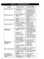
Troubleshooting
..................................
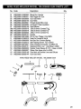
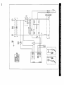
Wiring Diagram ....................................
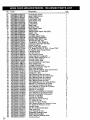
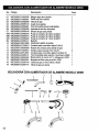
Parts List ..............................................
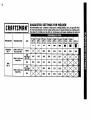
Suggested Settings ............................
15
16
16
16
16
16
16
16
17
17
18
18
19
20
20
21
21
21
21
22
22
22
23
23
25
26
30
Welder
For three years from the date of purchase, if any part of this welder, except for the gun or
cables, fails due to a defect in material or workmanship,
return it to your nearest Sears Parts &
Repair Center, and it will be repaired free of charge. Sears will repair the gun or cables free of
charge for only one year from the date of purchase. This warranty does not cover expendable
parts such as contact tips or nozzles, which are consumed during normal welder operation.
This warranty applies only while this product is used in the United States. This warranty gives
you specific legal rights, and you may also have other rights which vary from state to state.
Sears, Roebuck
and Co., D/817WA,
Hoffman
Estates,
IL 60179
This Welder User's guide provides specific information about your wire feed welder. It is to be used
together with the Welding Instruction Guide to provide all of the information needed to safely and
effectively use your wire feed welder. The information in this book applies to your specific model of
wire feed welder and gives instructions on set-up, installation and actual use of the welder.
2
Note:
•
Every craftsman respects the tools with
which they work. They know that the tools
represent years of constantly improved
designs and developments.
The true
craftsman also knows that tools are
dangerous if misused or abused.
Reading this operator's manual before using
the welder will enable you to do a better,
safer job. Learn the welder's applications
and ILmitations as well as the specific
poter_i'al hazards peculiar to welding.
IMPORTANT SAFETY
INFORMATION
•
The following safety alert symbols identify
important safety messages in this manual.
When you see one of the symbols shown
here, be alert to the possibility of personal
injury and carefully read the message that
follows.
This symbol indicates that the
possibility of electric shock hazard
exists during the operation of the
step(s) that follow.
Tills symbol indicates that the
possibility of fire hazard exists
during the operation of the step(s)
that follow.
The following safety information is provided
as guidelines to help you operate your new
welder under the safest possible conditions.
Any equipment that uses electrical power
can be potentially dangerous to use when
safety or safe handling instructions are not
known or not followed. The following safety
information is provided to give the user the
information necessary for safe use and
operation.
This symbol indicates that the
helmet must be worn during the
step(s) that follow to protect
against eye damage and burns
due to flash hazard.
A procedure step preceded by a
WARNING is an indication that the next step
contains a procedure that might be injurious
to a person if proper safety precautions are
not heeded.
This symbol indicates that the
possibility of being burned by hot
slag exists during operation of the
step(s) that follow.
A procedure preceded by a CAUTION is an
indication that the next step contains a
procedure that might damage the equipment
being used.
A NOTE may be used before or after a
procedure step to highlight or explain
something in that step.
READ ALL SAFETY INSTRUCTIONS
CAREFULLY
before attempting to install,
operate, or service this welder. Failure to
comply with these instructions could result in
personal injury and/or property damage.
RETAIN THESE INSTRUCTIONS
FUTURE REFERENCE.
FOR
This symbol indicates that the
possibility of toxic gas hazard
exists during operation of the
step(s) that follow.
This symbol indicates that the eye
protection should be worn to
protect against flying debris in
the following step(s).
This symbol indicates that the
possibility of injury or death exists
due to improper handling and
maintenance of compressed gas
cylinders or regulators.
Published standards on safety are
available. They are listed in ADDITIONAL
SAFETY INFORMATION
at the end of
this SAFETY SUMMARY.
The National Electrical Code, Occupation
Safety and Health Act regulations, local
industrial codes and local inspection
requirements also provide a basis for
equipment installation, use, and service.
3
SHOCK HAZARD
•
WARNING
ELECTRIC SHOCK CAN KILLI To reduce
the risk of death or serious injury from shock,
read, understand, and follow the following
safety instructions. In addition, make certain
that anyone else who uses this welding
equipment, or who is a bystander in the
welding area understands and follows these
safety instructions as well.
IMPORTANT!
TO REDUCE THE RISK
OF DEATH, INJURY, OR PROPERTY
DAMAGE, DO NOT ATTEMPT
OPERATION
of this welding equipment
until you have read and understand the
following safety summary.
Do not, in any manner, come into
physical contact with any part of the
welding current circuit. The welding
current circuit includes:
a. the work piece or any conductive
material in contact with it,
b. the ground clamp,
c. the electrode_ or welding wire,
d. any metal parts on the electrode
holder, or wire feed gun.
Do not weld in a damp area or come in
contact with a moist or wet surface.
Do not attempt to weld if any part of
clothing or body is wet.
Do not allow the welding equipment to
come in contact with water or moisture.
Do not drag welding cables, wire feed
gun, or welder power cord through or
allow them to come into contact with
water or moisture.
Do not touch welder, attempt to turn
welder on or off if any part of the body or
clothing is moist or if you are in physical
contact with water or moisture.
Do not attempt to plug the welder into the
power source if any part of body or clothing is moist, or if you are in physical
contact with water or moisture.
Do not connect welder work piece clamp
to or weld on electrical conduit.
Do not alter power cord or power cord
plug in any way.
Do not attempt to plug the welder
4
•
•
•
into the power source if the ground prong
on power cord plug is bent over, broken
off, or missing.
Do not allow the welder to be connected
to the power source or attempt to weld if
the welder, welding cables, welding site,
or welder power cord are exposed to any
form of atmospheric precipitation,
or salt
water spray.
Do not carry coiled welding cables around
shoulders, or any other part of the body,
when they are plugged into the welder.
Do not modify any wiring, ground
connections, switches, or fuses in this
welding equipment.
Wear welding gloves to help insulate
hands from welding circuit.
Keep all liquid containers far enough
away from the welder and work area so
that if spilled, the liquid can not possibly
come in contact with any part of the
welder or electrical welding circuit.
Replace any cracked or damaged parts
that are insulated or act as
insulators such as welding cables, power
cord, or electrode holder IMMEDIATELY.
FLASH HAZARDS
WARNING
ARC RAYS CAN INJURE EYES AND
BURN SKIN! To reduce the risk of injury
from arc rays, read, understand, and follow
the following safety instructions. In addition,
make certain that anyone else that uses this
welding equipment, or is a bystander in the
welding area understands and follows these
safety instructions as well. Headshields and
filter should conform to ANSI Z87.1 standards.
Do not look at an electric arc without proper
protection. A welding arc is extremely bright
and intense and, with inadequate or no eye
protection, the retina can be burned, leaving a permanent dark spot in the field of
vision. A shield or helmet with a number 10
shade filter lens (minimum) must be used.
Do not strike a welding arc until all
bystanders and you (the welder) have
welding shields and/or helmets in place.
Do not wear a cracked or broken
helmet and replace any cracked or
broken filter lenses IMMEDIATELY.
Do not allow the uninsulated portion
of the wire feed gun to touch the ground
clamp or grounded work to prevent an
arc flash from being
created on contact.
Provide bystanders with shields or
helmets fitted with a #10 shade filter lens.
Wear protective clothing. The intense
light of the welding arc can burn the skin
in much the same way as the sun, even
through light-weight clothing. Wear dark
clothing of heavy material. The shirt worn
should be long sleeved and the collar
kept buttoned to protect chest and neck.
Protectagainst REFLECTEDARC RAYS.
Arc rays can be reflectedoff shiny surfaces
such as a glossy paintedsurface,
aluminum,stainless steel, and glass. It is
possiblefor your eyes to be injured by
reflectedarc rays even when wearing a
protectivehelmet or shield. If welding with a
reflectivesurface behind you, arc rays can
bounce off the surface, then off the filter
lens on the inside of your helmet or shield,
then into your eyes. If a reflective
backgroundexists in your welding area,
either remove it or cover it with something
non-flammableand non-reflective.
Reflectivearc rays can also cause skin
burn in additionto eye injury.
•
•
•
•
FIRE HAZARDS
WARNING
FIRE OR EXPLOSION
CAN CAUSE
DEATH, INJURY, AND PROPERTY DAMAGE! To reduce the risk of death, injury, or
property damage from fire or explosion, read,
understand, and follow the following safety
instructions.
In addition, make certain that
anyone else that uses this welding equipment, or is a bystander in the welding area,
understands and follows these safety
instructions as well. REMEMBER!
Arc welding by nature produces sparks, hot
spatter, molten metal drops, hot slag, and hot
metal parts that can start fires, burn skin, and
damage eyes.
•
Do not wear gloves or other clothing that
contains oil, grease, or other
flammable substances.
Do not wear flammable hair
preparations.
Do not weld in an area until it is checked
and cleared of combustible and/or
flammable materials. BE AWARE that
sparks and slag can fly 35 feet and can
pass through small cracks.and openings.
If work and combustibles cannot be
separated by a minimum of 35 feet,
protect against ignition with suitable,
snug-fitting, fire resistant, covers or
shields.
Do not weld on walls until checking for
and removing combustibles touching the
other side of the walls.
Do not weld, cut, or perform other such
work on used barrels, drums, tanks, or
other containers that had contained a
flammable or toxic substance. The
techniques for removing flammable substance and vapors, to make a used
container safe for welding or cutting, are
quite complex and require special
education and training.
Do not strike an arc on a compressed
gas or air cylinder or other pressure
vessel. Doing so will create a brittle area
that can result in a violent rupture
immediately or at a later time as a result
of rough handling.
Do not weld or cut in an area where the
air may contain flammable dust (such as
grain dust), gas, or liquid vapors (such as
gasoline).
Do not handle hot metal, such as the work
piece or electrode stubs, with bare hands.
Wear leather gloves, heavy long sleeve
shirt, cuffless trousers, high-topped
shoes, helmet, and cap. As necessary,
use additional protective clothing such as
leather jacket or sleeves, fire resistant
leggings, or apron. Hot sparks or metal
can lodge in rolled up sleeves, trouser
cuffs, or pockets. Sleeves and collars
should be kept buttoned and pockets
eliminated from the shirt front.
Have fire extinguisher equipment handy
for immediate user A portable chemical
fire extinguisher, type ABC, is
recommended.
Wear ear plugs when welding overhead
5
chlorinated hydrocarbons, such as
trichloroethylene and perchloroethylene,
can be decomposed by the heat of an
electric arc or its ultraviolet radiation.
These actions can cause PHOSGENE, a
HIGHLY TOXIC gas to form, along with
other lung and eye-irritating gasses. Do
not weld or cut where these solvent
vapors can be drawn into the work area
or where the ultraviolet radiation can
penetrate to areas containing even very
small amounts of these vapors.
Do not weld in a confined area unless it
is being ventilated or the operator (and
anyone else in the area) is wearing an
air-supplied respirator.
Stop welding if you develop momentary
eye, nose, or throat irritation as this
indicates inadequate ventilation. Stop
work and take necessary steps to
improve ventilation in the welding area.
Do not resume welding if physical
discomfort persists.
to prevent spatter or slag from falling
into ear.
Make sure welding area has a good,
solid, safe floor, preferably concrete or
masonry, not tiled, carpeted, or made of
any other flammable material.
Protect flammable walls, ceilings,
and floors with heat resistant covers
or shields.
Check welding area to make sure
it is free of sparks, glowing metal or
slag, and flames before leaving the
welding area.
FUME HAZARDS
WARNING
FUMES, GASSES, AND VAPORS CAN
CAUSE DISCOMFORT,
ILLNESS, AND
DEATH! To reduce the risk of discomfort,
illness, or death, read, understand, and
follow the following safety instructions.
In
addition, make certain that anyone else that
uses this welding equipment or is a
bystander in the welding area, understands
and follows these safety instructions as well.
Do not weld in an area until it is checked
for adequate ventilation as described in
ANSI standard #Z49.1. If ventilation is
not adequate to exchange all fumes and
gasses generated during the welding
process with fresh air, do not weld unless
you (the welder) and all bystanders are
wearing air-supplied respirators.
Do not heat metals coated with, or that
contain, materials that produce toxic
fumes (such as galvanized steel), unless
the coating is removed. Make certain the
area is well ventilated, and the operator
and all bystanders are wearing air-supplied respirators.
Do not weld, cut, or heat lead, zinc,
cadmium, mercury, beryllium, or similar
metals without seeking professional
advice and inspection of the ventilation of
the welding area. These metals produce
EXTREMELY
TOXIC fumes which can
cause discomfort, illness, and death.
Do not weld or cut in areas that are near
chlorinated solvents. Vapors from
6
COMPRESSED GASSES AND
EQUIPMENT HAZARDS
WARNING
IMPROPER HANDLING AND
MAINTENANCE
OF COMPRESSED
GAS
CYLINDERS AND REGULATORS
CAN
RESULT IN SERIOUS INJURY OR DEATH!
To reduce the risk of injury or death from
compressed gasses and equipment hazards,
read, understand, and follow the following
safety instructions. In addition, make certain
that anyone else who uses this welding
equipment or a bystander in the welding area
understands and follows these safety
instructions as well.
•
•
Do not use flammable gasses with MIG
welders. Only inert or nonflammable
gasses are suitable for MIG welding.
Examples are Carbon Dioxide, Argon,
Helium, etc. or mixtures of more than one
of these gasses.
Do not attempt to mix gasses or refill a
cylinder yourself. Do not expose
cylinders to excessive heat, sparks, slag
and flame, etc. Cylinders exposed to
temperatures above 130°F will require
•
•
•
•
•
•
•
•
•
•
water spray cooling.
Do not expose cylinders to electricity of
any kind.
Do not use a cylinder or its contents for
anything other than its intended use. Do
not use as a support or roller.
Do not locate cylinders in passageways
or work area where they may
be struck.
Do not use a wrench or hammer to open
a cylinder valve that cannot be opened
b3i-hand. Notify your supplier.
D_ not modify or exchange gas
cylinder fittings.
Do not deface or alter name, number or
other markings on a cylinder. Do not rely
on cylinder color to identify
the contents.
Do not connect a regulator to a cylinder
containing gas other than that for which
the regulator was designed.
Do not attempt to make regulator repairs.
Send faulty regulators to manufacturer's
designated repair center for repair.
Do not attempt to lubricate a regulator.
Always change cylinders carefully to
prevent leaks and damage to their walls,
valves, or safety devices.
Always secure cylinders with a steel chain
so that they cannot be knocked over.
Always protect a cylinder, especially the
valve, from bumps, falls, falling objects
and weather. Remember that gasses in
the cylinders are under pressure and
damage to a regulator can cause the
regulator or portion of the regulator to be
explosively ejected from the cylinder.
Always make certain the cylinder cap is
securely in place on the cylinder,
whenever the cylinder is moved.
Always close the cylinder valve and
immediately remove a faulty regulator
from service, for repair, if any of the
following conditions exist.
Gas leaks externally.
Delivery pressure continues to rise with
down stream valve closed.
The gauge pointer does not move off the
stop pin when pressurized or fails to
return to the stop pin after pressure is
released.
ADDITIONAL
SAFETY
INFORMATION
For additional information concerning
welding safety, refer to the following
standards and comply with them as
applicable.
•
•
•
•
•
ANSI Standard Z49.1 - SAFETY IN
WELDING AND CUTTING - obtainable
from the American Welding Society, 550
NW Le Jeune Road, Miamil FL 33126
Telephone (800) 443-9353,
Fax (30_) 443-7559 - www.amweld.org
or www.,_ws:org
ANSI Standard Z87.1 - SAFE PRACTICE FOR OCCUPATION AND
EDUCATIONAL
EYE AND FACE
PROTECTION
- obtainable from the
American National Standards Institute,
11 West 42nd St., New York, NY 10036
Telephone (212) 642-4900,
Fax (212) 398-0023 - www.ansi.org
NFPA Standard 51B - CUTTING AND
WELDING PROCESS - obtainable from
the National Fire Protection Association,
1 Batterymarch Park, P.O. Box 9101,
Quincy, MA 02269-9101
Telephone (617) 770-3000
Fax (617) 770-0700 - www.nfpa.org
OSHAStandard
29 CFR, Part 1910,
Subpart Q., WELDING, CUTTING AND
BRAZING - obtainable from your state
OSHA office or U.S. Dept. of Labor
OSHA, Office of Public Affairs, Room
N3647, 200 Constitution Ave.,
Washington,
DC 20210 - www.osha.gov
CSA Standard Wl17.2 - Code for
SAFETY IN WELDING AND CUTTING. obtainable from Canadian Standards
Association,
178 Rexdale Blvd.,
Etobicoke, Ontario M9W 1R3 www.csa.ca
American Welding Society Standard
A6.0. WELDING AND CUTTING
CONTAINERS
WHICH HAVE HELD
COMBUSTIBLES.
- obtainable from the
American Welding Society, 550 NW Le
Jeune Road, Miami, FL 33126
Telephone (800) 443-9353,
Fax (305) 443-7559 - www.amweld.org
or www.aws.org
7
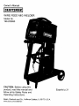
DESCRIPTION
Your new MIG (Metal Inert Gas) wire feed
welder is designed for maintenance and
sheet metal fabrication. The welder consists
of a single-phase power transformer,
stabilizer, rectifier, and a unique built-in
control/feeder.
Now you can weld sheet metal from 24
gauge up to 3/16 inch thick with a single
pass. You can weld thicker steel with
beveling and multiple pass techniques. Table
1 lists your MIG welder specifications.
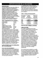
Table 1. Welder
Specifications
Primary (input) volts 120 Vac
Primary (input) Amps 13
Phase Single
Frequency 60Hz
Secondary (output) volts 21
Secondary (UL output) amps 85
Open Circuit Volts (Max.) 30 Vdc
Duty Cycle Rating 40%
MIG welders equipped
with gas are capable
of welding with 0.024.(_0:6mm) and 0.030
(0.8mm) solid steel wire on dc reverse
polarity and with 0.030 (0.8mm)
self-shielding
flux-core wire on dc straight
polarity. Larger, 0.035 inch (0.9mm) diameter
solid steel wire, on dc reverse polarity may
also be used on this welder. The use of
larger diameter wire makes welding difficult
and the results cannot be guaranteed. Use of
larger than .035 diameter wire is not
recommended.
WELDER OPERATING
CHARACTERISTICS
DUTY CYCLE
The duty cycle rating of a welder defines
how long the operator can weld and how
long the welder must be rested and cooled.
Duty cycle is expressed as a percentage of
10 minutes and represents the maximum
welding time allowed. The balance of the
10-minute cycle is required for cooling.
Your new welder has a duty cycle rating of
40% at the rated output. This means that you
8
can weld for four (4) minutes out of 10 with
the remaining six (6) minutes required for
cooling. (See Table 2).
Table 2. Duty Cycle Ratings
Duty
Cycle
Rating
Maximum
Welding
Time
Required
Resting
Time
20%
2 minutes
8 minutes
60%
80%
100%
6 minutes
8 minutes
10 minutes
4 minutes
2 minutes
0 minutes
INTERNAL THERMAL
PROTECTION
CAUTION
Do not constantly exceed the duty cycle or
damage to the welder can result. If you
exceed the duty cycle of the welder, an
internal thermal protector will open, shutting
off all welder functions except the cooling
fan. If this happens, DO NOT SHUT OFF
THE WELDER. Leave the welder turned on
with the fan running. After cooling, the
thermal protector will automatically
reset and
the welder will function normally again.
However you should wait at least ten
minutes after the thermal protector opens
before resuming welding. You must do this
even if the thermal protector resets itself
before the ten minutes is up or you may
experience less than specified duty cycle
performance.
If you find that the welder will not weld for
two minutes without stopping, reduce the
wire speed slightly and tune in the welder at
the lowest wire speed setting that still
produces a smooth arc. Welding with the
wire speed set too high causes excessive
current draw and shortens the duty cycle.
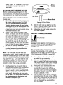
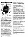
Handle
Gun Cable
Wire Speed
Voltage
Selector
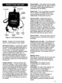
Power Switch - This switch turns the welder
ON and OFF. (Make sure the power switch is
in the OFF position before performing any
maintenance on the welder.)
Power Cord - This is a standard, grounded
120 volt power cord. (Make sure you are
using a properly grounded 120 Vac, 60Hz,
single phase, 20 amp power source.)
Power
_r!und
Welding
Gun
Figure
Jnd Clamp
Cable
Power
Ground Clamp -Attaching
the ground
clamp to your work piece "completes" the
welding current circuit. You must attach the
ground clami_ to-the metal you are welding. If
the ground clamp is not connected to the
metal work piece you intend to weld, the
welder will not have a completed circuit and
you will be unable to weld. A poor connection
at the ground clamp will waste power and
heat. Scrape away dirt, rust, scale, oil or
paint before attaching the ground clamp.
Cord
1. Model 20569 Welder
Handle - Rugged, top mounted handle
allows for easy transport of your welder.
Wire Speed Control - Use this dial to adjust
the speed at which the welder feeds wire to
the gun. 1 is the slowest wire feed speed, 10
is the highest. You will need to adjust or
"tune-in" your wire speed for different welding
conditions (thickness of metals, gas -vsgasless welding, metal type, wire size, etc.).
When the wire speed is properly "tuned-in"
the welding wire will melt into the material you
are welding as quickly as it is fed through the
welding gun.
Voltage SelectorThis four position dial
adjusts the voltage or "heat" of your welder.
A is the lowest and D is the highest. Different
materials and material thickness will require
different voltage settings. You will need to
adjust your voltage accordingly for different
welding conditions. By properly adjusting
your voltage settings and wire feed speed,
you will enable clean, precision welds. (Refer
to the Suggested Settings Chart on p.30 of
this manual OR on the inside of the door of
the welder.)
Ground Cable - The ground cable connects
the ground clamp to the internal workings of
the welder.
Welding Gun and Cable - The welding gun
controls the delivery of the welding wire to
the material to be welded. The welding wire
is fed through the welding cable and welding
gun when the welding gun trigger is pulled.
You will need to install a contact tip and
welding nozzle to the end of the welding gun,
as described later in this manual, prior to
welding.
Welding Terms
Now that you are familiar with the main parts
of the welder, make note of the following
terms. You will see them used throughout
this manual.
weld puddle: The localized volume
of molten metal in a weld prior to its
solidification.
weld angle: The angle of the welding wire,
as it extends from the welding gun, in
relation to the item being welded.
slag: The protective coating that forms on
the surface of molten metal.
arc: A sustained luminous discharge of
electricity across a gap in a circuit.
welding bead: The extended build up of a
weld, made by pushing or pulling the weld
puddle.
9
POWER SOURCE CONNECTION
POWER REQUIREMENTS
This welder is designed to operate on a
properly grounded 120 volt, 60Hz, singlephase alternating current (ac) power source
fused with a 20 amp time delayed fuse or
circuit breaker. It is recommended that a
qualified electrician verify the ACTUAL
VOLTAGE at the receptacle into which the
welder will be plugged and confirm that the
receptacle is properly fused and grounded.
The use of the proper circuit size can
eliminate nuisance circuit breaker tripping
when welding.
DO NOT OPERATE THIS WELDER if the
ACTUAL power source voltage is less than
105 volts ac or greater than 132 volts ac.
Contact a qualified electrician if this problem
exists. Improper performance and/or damage
to the welder will result if operated on
inadequate or excessive power.
CONNECT
TO POWER
SOURCE
Select a properly grounded extension cord
that will mate directly with the power source
receptacle and the welder power cord without
the use of adapters. Make certain that the
extension is properly wired and in good
electrical condition.
Extension cords must be a #12 gauge cord at
the smallest. Do not use an extension cord
over 25 ft. in length.
ASSEMBLING
THE
WELDER
The following procedures describe the
process required to assemble, install,
maintain, and prepare to weld with your new
wire feed welder.
UNPACKING
THE WELDER
1. Remove any cartons or bags containing
parts/accessories. (Most parts are
shipped INSIDE the welder door.)
2. Open the cartons or bags packed with your
welder and inspect their contents for damage.
3. Layout the parts and compare them to
the the packing list in Table 3 to familiarize yourself with the parts and what they
are called. This will help you when
reading the manual.
PACKING LIST
Table 3 contains a list of the items you will
find packed in the carton.
Table 3. P_cking List
High voltage danger from power source!
Consult a qualified electrician for proper
installation of receptacle at the power source.
This welder must be grounded while in use to
protect the operator from electrical shock. If
you are not sure if your outlet is properly
grounded, have it checked by a qualified
electrician. Do not cut off the grounding prong
or alter the plug in any way and do not use
any adapters between the welder's power
cord and the power source receptacle. Make
sure the POWER switch is OFF then connect
your welder's power cord to a properly
grounded 120Vac, 60 Hz, single phase, 20
amp power source.
EXTENSION
CORDS
For optimum welder performance, an
extension cord should not be used unless
absolutely necessary. If necessary, care
must be taken in selecting an extension cord
appropriate for use with your specific welder.
10
ITEM
Welder
Face Shield
Face Shield Handle
Shaded Lens
Welder Handle
Handle Screws
Front and Back Foot
Foot Screws
Wire Brush/Hammer
Parts Bag
Contact Tip 0.024
Contact Tip 0.030
Contact Tip 0.040
Nozzle
Wire .030 Fluxcore
Manual, Instruction
QTY.
1
1
1
1
1
2
1 ea.
4
1
1
5
5
5
2
1/2 lb.
1
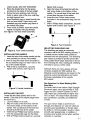
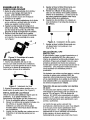
ASSEMBLE
THE FACE SHIELD
1. Remove the lens retaining pegs and
shield handle nut from the arm of the
shield handle. (DO NoT DISCARDT)
Place the shaded lens into the space
provided on the inside of the face shield.
3. Screw the lens retaining nuts into the
holes to either side of the lens until they
are tight against lens.
4. Insert threaded peg on shield handle into
hole on face shield. Press firmly until
threaded peg and smaller peg below it
are locked into place.
5. From inside of shield, screw the shield
handle nut tightly onto peg threads.
See F_ur e 2 for face shield assembly.
2.
5.
6.
7.
tighten both screws.
Align the holes of the back foot with the
rear screw holes on the bottom of the
welder. The curved face of the back foot
should face the rear of the welder.
Insert the two Phillips head screws
(included in the accessories bag) into the
holes.
With a Phillips head screwdriver, securely
tighten both screws. (see Figure 4)
II
I
1
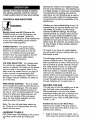
Figure 4. Feet Installation
Figure
2. Face Shield Assembly
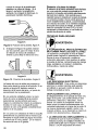
INSTALLING THE HANDLE
1. Insert the tabs of the welder handle into the
slots provided on the top of the welder.
2. Insert a large flat head screw (included in
the accessories
bag) into each hole on the
top of the welder handle.
3. With a flat tip screwdriver, securely
tighten both screws. (see Figure 3)
1
1
!
Figure
I
3. Handle
Installation
INSTALLING
THE FEET
Locate the two black plastic feet for the
welder. (The front foot is slightly larger than
the back foot.)
1. Lay the welder on its side.
2. Align the holes of the front foot with the
front screw holes on the bottom of the
welder. The curved face of the front foot
should face the front of the welder.
3. Insert the two Phillips head screws (included in the accessories bag) into the holes.
4. With a Phillips head screwdriver, securely
SELECTING SHIELDING GAS
The shielding gas plays an extremely
important role in the MIG welding process. It
is critical that the molten weld puddle be
shielded from the atmosphere. The shielding
gas creates a protective pocket around the
weld puddle which keeps impurities in the air
from infecting the weld. Inadequate shielding
will result in porous, brittle welds.
Although there are many gasses and gas
mixtures available for MIG welding, the
following recommendations
are based on the
electrical output characteristics
and metal
thickness capabilities of this specific
MIG welder.
Gas Selection For Steel Welding With
Steel Wire
For either mild or low carbon (High Strength
Structural) steel, use a gas mixture of 75%
Argon and 25% Carbon Dioxide. DO NOT
USE Argon gas concentrations higher than
75% on steel. The result will be extremely
poor penetration, porosity, and brittleness
of weld.
This gas mixture helps to prevent burn
through and distortion on very thin steel yet
provides good penetration on thicker steel.
Its ability to minimize spatter results in clean,
smooth weld appearances.
In addition, it
provides good puddle control when welding
vertically or overhead.
11
Gas Selection For Stainless Steel Welding
The best shielding gas for stainless steel
welding is a mixture of 90% Helium, 7.5%
Argon, and 2.5% Carbon Dioxide. However,
100% Argon can also be used, but an
increase in the area being heated by the arc
will be experienced causing slightly greater
distortion of the base metal.
Gas Selection For Steel Welding With
Silicon Bronze Wire
Use only pure Argon when welding steel with
Silicon-Bronze wire.
INSTALL
THE SHIELDING
GAS
WARNING
IMPROPER HANDLING AND MAINTENANCE OF COMPRESSED
GAS CYLINDERS AND REGULATORS
CAN RESULT
IN SERIOUS INJURY OR DEATH! Always
secure gas cylinders to the welding cart, a
wall, or other fixed support to prevent the
cylinder from falling o_er and rupturing.
Read, understand, and follow all the COMPRESSED GASSES AND EQUIPMENT
HAZARDS in the SAFETY SUMMARY at the
front of this manual. Secure your gas cylinder to the welding cart, or other fixed support.
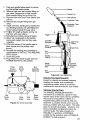
1.
2.
3.
4.
5.
12
Remove the protective cap from the cylinder and inspect the regulator connecting
threads for dust, dirt, oil, and grease.
Remove any dust or dirt with a clean
cloth. DO NOT ATTACH YOUR REGULATOR IF OIL, GREASE, OR DAMAGE
ARE PRESENT.
Open the cylinder valve FOR JUST AN
INSTANT to blow out any foreign matter
inside the valve port. Never aim the open
valve cylinder port at yourself or
bystanders.
Screw the regulator into the cylinder
valve and tighten with a wrench.
Firmly push the gas hose over barbed fittings on back of welder and regulator.
Secure both ends of hose onto barbed fittings with hose clamps.
CHECK
THE GAS FLOW
WARNING
IMPROPER HANDLING AND MAINTENANCE
OF COMPRESSED GAS CYLINDERS AND
REGULATORS CAN RESULT IN SERIOUS
INJURY OR DEATH. To reduce the risk of
injury or death, always stand to the side of the
cylinder opposite the regulator when opening
the cylinder valve, keeping the cylinder valve
between you and the regulator. Never aim the
open cylinder valve port at yourself or
bystanders. Failure to comply with this warning
could result in serious personal injury.
Note: If the cylinder you have is equipped
with male regulator connecting threads
instead of female, you will need to obtain a
special compressed gas cylinder adaptor
from your gas supplier to install between
your gas cylinder and regulator.
-The gas control function does not
require the welder to be turned on or
plugged in.
-To avoid damage to your regulator, make
sure you have the regulator valve closed
before opening the cylinder valve.
1. Slowly crack open the cylinder valve,
then turn open ALL THE WAY.
2. Pull the trigger on the gun to allow the
gas to flow. KEEP THE TRIGGER
PULLED. Listen and feel for gas flowing
from the end of the welding gun. If your
regulator has no adjustment, it has been
preset at the factory for a flow of 20 cubic
feet per hour. If your gas regulator has an
adjustment to control the gas flow rate,
turn the adjustment key clockwise to
increase gas flow; counterclockwise
to
reduce flow. For most welding, the gas
flow should be set at 15-20 cubic feet per
hour. If no gas is heard or felt, verify all
steps involved in connecting the gas.
3. Release the trigger.
Note: If welding outside or in a draft, it may
become necessary to set up a wind break to
keep the shielding gas from being blown
from the weld area.
-MAKE SURE TO TURN OFF THE GAS
CYLINDER VALVE WHEN DONE
WELDING.
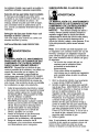
, Drive
Roller
ALIGN AND SET THE DRIVE ROLLER
Before installing any welding wire into the
unit, the proper sized groove must be placed
into position on the wire drive mechanism.
Change the drive roller according to the following steps:
1. Remove the drive tension by unscrewing
tl_e tension adjusting screw (ALL THE
V_AY in a counterclockwise
direction).
The drive tension screw will come loose,
allowing you to pull the drive tension arm
up away from the drive roller. Make sure
to keep the screw and the spring in place
with the drive tension arm.
2. If there is wire already installed in the
welder, roll it back onto the wire spool by
hand-turning the spool counter-clockwise.
Be careful not to allow the wire to come
out of the rear end of the gun without
holding onto it or it will unspool itself. Put
the end of the wire into the hole on the
outside edge of the wire spool and bend
it over to hold the wire in place. Remove
the spool of wire from the welder.
3. Loosen the drive roller set screw with the
provided hex wrench and pull the drive
roller off the drive shaft.
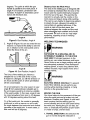
Note: The drive roller has two wire size
grooves built into it. When installing the drive
roller the number stamped on the drive roller
for the wire size you are using should be facing away from you. If you can read the wire
size you are using on the drive roller, it is
installed backwards. Use only the proper
size drive roller when using your welder.
,
Find the side of the drive roller that is
stamped with the same wire diameter as
that of the wire being installed (see
Figure 5, and if in metric, see DESCRIPTION). Push the drive roller onto the
motor shaft, aligning the set screw with
the flat side of the drive shaft. Make sure
the side stamped with the desired wire
diameter is away from you.
_Motor
Shaft
Rgure 5. Drive Roller
5.
6.
Slide the roller onto the shaft so that the
groove in the roller lines up with the inlet
tube and the welding gun liner.
Tighten the set screw, while holding the
drive roller in place.
INSTALL
I
THE WELDING
WIRE
f]WARNING
Electric shock can kill! Always turn the
POWER switch OFF and unplug the power
cord from the ac power source before
installing wire.
Be very careful when removing the welding
nozzle. The contact tip on this welder is
electrically hot as long as POWER is turned
ON. Make certain POWER is turned OFF.
1.
2.
3.
4.
Remove the nozzle and contact tip from
the end of the gun assembly.
Make sure the proper groove on the drive
roller is in place for the wire being installed.
If the proper groove is not in place, change
the drive roller as described above.
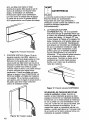
Unwrap the spool of wire and then find
the leading end of the wire (it goes
through a hole in the outer edge of the
spool and is bent over the spool edge to
prevent the wire from unspooling), BUT
DO NOT UNHOOK IT YET.
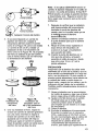
Place the spool on the spindle in such a
manner that when the wire comes off the
spool, it will look like the top illustration in
Figure 6. The welding wire should always
come off the top of the spool into the
drive mechanism.
13
Note: If TOO MUCH tension is applied to the
wire spool, the wire will slip on the drive
roller or will not be able to feed at all. If TOO
LITTLE tension is applied, the spool of wire
will want to unspool itself. Readjust the drive
brake tension as necessary to correct for
either problem.
Right Way
Figure 6. Wire Installation
.
If you are installing a four-inch spool of
wire, install the drive brake hardware on
the top of the spool of wire according to
figure 7A. If you are installing an eightinch spool, install the spindle adapter and
drive brake hardware as shown in Figure
7B. The purpose of the drive brake is to
cause the spool of wire to stop turning at
nearly the same moment that wire
feeding stops.
7. After checking to make sure that your
welder is disconnected
from the ac power
source, free the leading end of the wire
from the spool, but do not let go of it until
told to do so, or the wire will unspool
itself.
8. Use a wire cutter, cut the bent end off the
leading end of the wire so that only a
straight leading end remains.
9. Loosen the tension adjusting screw
holding the drive tension arm in place
and lift the tension arm up off the drive
roller.
10. Insert the leading end of the wire into the
inlet guide tube. Then push it across the
drive roller and into the gun assembly
about six inches.
CAUTION
I
I
I
t
I
I
I
I
I
I
I
I
I
I
I
I
Figure 7A. Drive
Brake Hardware
Installation
6.
14
Figure 7B. Spindle
Adapter and Drive
Brake Installation
Once the drive brake hardware is installed,
set the spool tension. With one hand, turn
the wire spool and continue turning it while
adjusting the tension on the spool. With
your free hand, tighten (tum clockwise) the
knob that holds the spool in place. Stop
tightening when drag is felt on the wire
spool that you are turning, then stop handturning the wire spool.
Make certain that the welding wire is actually
is going into the gun liner. Be very sure it has
not somehow been accidentally been routed
alongside the liner or even in some other
direction. If this should happen, the wire
could feed inside the cable casing or take a
right angle and follow the wires and gas
hose inside the welder. It could also feed
back on itself jamming up the mechanism.
11. Line the wire up in the inside groove of
the drive roller, then allow the drive tension arm to drop onto the drive roller.
12. Tighten (turn clockwise) the drive tension
adjusting screw until the tension roller is
applying enough force on the wire to
prevent it from slipping out of the drive
assembly.
13. Let go of the wire.
14. Connect the welder power cord to the ac
power source. Turn the welder ON by
setting the VOLTAGE switch to the voltage (heat) setting recommended
for the
gauge metal that is to be welded. Refer
to the label mounted on the cover, inside
the drive compartment,
for recommended
voltage (heat) settings for your welding
job. The VOLTAGE selector controls the
weld heat. There are four voltage heat
15.
16.
17.
18.
selections (lettered A through D) available
on this welder. Position A provides the
lowest voltage (heat) and position D the
highest voltage (heat).
Set the WIRE SPEED control to the
middle of the wire speed range.
Straighten the gun cable and pull the
trigger on the welding gun to feed the
wire through the gun assembly.
When at least an inch of wire sticks out
pa,._tthe end of the gun, release the
trigger.
Select a contact tip stamped with the
same diameter as the wire being used. If
stamped in metric see DESCRIPTION.
Note: Due to inherent variances in flux-cored
welding wire, it may be necessary to use a
contact tip one size larger than your flux core
wire if wire jams occur.
19. Slide the contact tip over the wire
(protruding from the end of the gun).
Thread the contact tip into the end of the
gun and hand-tighten
securely.
20. Install the nozzle on the gun assembly.
For best results, coat the inside of the
nozzle with anti-stick spray or gel.
21. Cut off the excess wire that extends past
the end of the nozzle.
CHANGE
POLARITY
This welder allows you the capability to
change the welding current polarity. You may
select either dc Straight (dc - Flux Cored) or
dc Reverse Polarity (dc + MIG). For welding
steel with solid wire, stainless steel, flux cored
hardfacing of steel, and silicon bronze welding
of steel, select dc Reverse Polarity (dc +
MIG). When using self-shielding, flux-core
steel wire, use dc Straight Polarity (dc - Flux
Cored).
Change the polarity of your welder according
to the followi_lg procedure steps. Figure 6
shows what the polarity block should look like
for each polarity setting.
Electric shock can kill! Always turn the
power OFF and unplug the power cord from
the ac power source before changing polarity.
CAUTION
Do not use a ratchet, crescent or other lever
type wrench to tighten knobs on the polarity
block. The nuts must be hand tightened only.
Too much torque applied to one of the knobs
could cause the knob to break off.
1.
SET THE WIRE
DRIVE
TENSION
To reduce the risk of arc flash, make certain
that the wire coming out of the end of the
gun does not come in contact with work
piece, ground clamp or any grounded material during the drive tension setting process or
arcing will occur.
.
2.
Pull the trigger on the gun.
Turn the drive tension adjustment knob
clockwise, increasing the drive tension
until the wire seems to feed smoothly
without slipping.
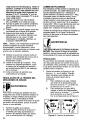
Remove the retaining knobs from the +
and - mounting posts on the Gas/No Gas
Board, located just below the drive motor
on the inside of your welder.
A. For Gasless welding, mount the
Ground Clamp ring terminal to the "+"
mounting post and the Torch ring terminal to the "-" mounting post.
B. For Gas (MIG) welding, mount the
Ground Clamp ring terminal to the "-"
mounting post and theTorch ring
terminal to the "+" mounting post.
See configuration shown in Figure 8.
NO
GAS
GAS
Figure 8. Changing Polarity
15
Operation of this welder consists of selecting
and adjusting operating controls for optimum
voltage (welding heat) and wire speed settings.
CONTROLS
ANDINDICATORS
WARNING
Electric shock can kill! Whenever the
POWER switch is in the ON position, the
welding circuit is activated. Under this
condition, an arc will occur if the welding wire
or any part of the welding circuit comes in
contact with welding ground.
POWER SWITCH - The power switch
supplies electrical current to the welder.
Whenever the power switch is in the ON
position, the welding circuit is activated.
ALWAYS turn the power switch to the OFF
position and unplug the welder before
performing any maintenance.
VOLTAGE SELECTOR; - The voltage selector controls the welding heat. The voltage
selector is lettered A-D. Letter A is the lowest
heat and letter D the highest. Refer to the
label under the welder hood (or on page 30
of this manual) for recommended
heat
settings for your welding job. Position D on
the Voltage Selector produces the rated output of 85 amps.
WIRE SPEED CONTROL - The wire speed
control adjusts the speed at which the wire is
fed out of the welding gun. The wire speed
needs to be closely matched (tuned-in) to
the rate at which it is being melted off. Some
things that affect wire speed selection are
the type and diameter of the wire being
used, the heat setting selected, and the
welding position to be used.
Note: The wire will feed faster without an
arc. When an arc is being drawn, the wire
speed will slow down.
LEARNING
Whether you have welded before or not, it is
important that you become familiar with your
new welder, its controls, and the results
achieved at different settings. We strongly
recommend that you practice with your new
welder on scrap metal trying different heat
settings, base metal thicknesses, and welding
positions for each type and size of wire you
will be using. By doing this you will gain a feel
for how changes in these welding variables
affect the weld.
Of course, if you have not welded before,
you will need to develop welding skills and
techniques as well.
The self-taught welder learns through a
process of trial and error. The best way to
teach yourself how to weld is with short periods of practice at regular intervals. All practice welds should be done on scrap metal
that can be discarded. Do not attempt to
make any repairs on valuable equipment
until you have satisfied yourself that your
practice welds are of good appearance
and
free of slag or gas inclusions. What you fail
to learn through practice will be learned
through mistakes and re-welds later on.
HOLDING
THE
GUN
The best way to hold the welding gun is the
way that feels most comfortable to you.
While practicing to use your new welder,
experiment holding the gun in different positions until you find the one that seems to
work best for you. Refer to WELDING POSITIONSp.18)
Position the Gun to the Work Piece
There are two angles of the gun nozzle in
relation to the work piece that must be considered when welding.
TO WELD
MIG (Metal Inert Gas) welding is the process
of uniting metallic parts by heating and
/O
allowing the metals to flow together through
the use of an electrical arc. The electrical arc
is created between a continuous consumable
wire electrode (the welding wire) and the
work piece. An inert shielding gas is used to
protect the weld puddle from contamination
and enhance the welding capabilities of the
electrical arc.
1. Angle A (Figure 9) can be varied, but in
most cases the optimum angle will be 60
degrees. The point at which the gun
handle is parallel to the work piece. If
angle A is increased, penetration will
increase. If angle A is decreased, penetration will decrease also.
m
i
i
Angle A
Figure 9. Gun Position, Angle A
.
Angle B (Figure 10) can be varied for two
reasons: to improve the ability to see the
arc in relation to the weld puddle and to
direct the force of the arc.
Angle B
Figure 10. Gun Position,
Angle B
The force of the welding arc follows a
straight line out of the end of the nozzle.
If angle B is changed, so will the direction of
arc force and the point at which penetration
will be concentrated.
On a butt weld joint, the only reason to vary
angle B from perpendicular
(straight up) to
the work piece would be to improve visibility
of the weld puddle. In this case, angle B can
be varied anywhere from zero to 45 degrees
with 30 degrees working about the best.
On a fillet
positioned
the angle
members
fillet weld
weld joint, the nozzle is generally
in such a manner so as to split
between the horizontal and vertical
of the weld joint. In most cases, a
will be 45 degrees.
Distance from the Work Piece
The end of the welding gun is designed with
the contact tip recessed from the end of the
nozzle and the nozzle electrically insulated
from the rest of the gun. This permits the
operator to actually rest the nozzle on the
work piece and drag it along while welding.
This can be very helpful to beginning welders
to steady the gun, allowing the welder to
concentrate on welding technique. If the
nozzle is held off the work piece, the
distance between the nozzle and the work
piece shoul_be
kept constant and should
not exceed 1_4 inch or the arc may begin
sputtering, signaling a loss in welding
performance
WELDING
TECHNIQUES
WARNING
EXPOSURE TO A WELDING ARC IS
EXTREMELY
HARMFUL TO THE EYES
AND SKIN! Prolonged exposure to the
welding arc can cause blindness and burns.
Never strike an arc or begin welding until you
are adequately protected. Wear flameproof
welding gloves, a heavy long sleeved shirt,
cuffless trousers, high topped shoes and a
welding helmet.
ELECTRIC SHOCK CAN KILL! To prevent
ELECTRIC SHOCK, do not perform any
welding while standing, kneeling, or lying
directly on the grounded work.
MOVING THE GUN
Gun travel refers to the movement of the gun
along the weld joint and is broken into two
elements: Direction and Speed. A solid weld
bead requires that the welding gun be
moved steadily and at the right speed along
the weld joint. Moving the gun too fast, too
slow, or erratically will prevent proper fusion
or create a lumpy, uneven bead.
1. TRAVEL DIRECTION is the direction
gun is moved along the weld joint in
the
17
relation to the weld puddle. The gun is either
PUSHED (see Figure 11) into the weld puddle or PULLED away from the weld puddle.
PUSH
Figure
Puddle
11. Travel
PULL
Direction
For most welding jobs you will pull the
gun along the weld joint to take advan- tage of the greater weld puddle visibility.
2. TRAVEL SPEED is the rate at which the
gun is being pushed or pulled along the
weld joint. For a fixed heat setting, the
faster the travel speed, the lower the
penetration and the lower and narrower
the finished weld bead. Likewise, the
slower the travel speed, the deeper the
penetration and the higher and wider the
finished weld bead.
TYPES
OF WELD
centered over the weld joint. This is the easiest type of bead to make.
Figure
12. Stringer
Bead
2. The WEAVE BEAD (Figure 13) is used
when you want to deposit metal over a wider
space than would be possible with a stringer
bead. It is made by weaving from side to
side while moving with the gun. It is best to
hesitate momentarily at each side before
weaving back the other way.
BEADS
The following paragrap_hs discuss
commonly used weldin_]'beads.
the most
Once you have the gun in position with the
wire lined up on the weld joint, lower your
helmet, pull the trigger and the arc will start.
In a second or two you will notice a weld
puddle form and the base of the bead be
ginning to build. It is now time to begin to
move with the gun. If you are just learning to
weld, simply move the gun in a straight line
and at a steady speed along the weld joint.
Try to achieve a weld with the desired
penetration and a bead that is fairly flat and
consistent in width.
Figure 13. Weave Bead
WELDING POSITIONS
There are four basic welding positions: flat,
horizontal, vertical, and overhead.
1. The FLAT POSITION (Figure 14) is the
easiest of the welding positions and is most
commonly used. It is best if you can weld in
the flat position if at all possible as good
results are easier to achieve.
As you become more familiar with your new
welder and better at laying some simple weld
beads, you can begin to try some different
weld bead types.
There are two basic types of weld beads, the
stringer bead and the weave bead.
1. The STRINGER BEAD (Figure 12) is
formed by traveling with the gun in a straight
line while keeping the wire and nozzle
18
Figure
14. Flat Position
2. The HORIZONTAL
POSITION (Figure 15)
is next in difficulty level. It is performed very
much the same as the flat weld except that
angle B (see HOLDING THE GUN - p.16) is
such that the wire, and therefore the arc force,
is directed more toward the metal above the
weld joint. This is to help prevent the weld
puddle from running downward while still
allowing slow enough travel speed to achieve
good penetration. A good starting point for
angle B is about 30 degrees DOWN from
being perpendicular to the work piece.
Figure
15. Horizontal
Position
3. The VERTICAL POSITION (Figure 16) is
the next most difficult position. Pulling the
gun from top to bottom may be easier for
many people, but in some instances it can
be difficult to prevent the puddle from
running downward. Pushing the gun from
bottom to top may provide better puddle
control and allow slower rates of travel
speed to achieve deeper penetration. When
vertical welding, angle B (see HOLDING
THE GUN - p.16) is usually always kept at
zero, but angle A will generally range from 45
to 60 degrees to provide better puddle
control.
]WARNING
Hot slag can cause fires and serious injury
from burns! Be sure to wear protective clothing and eye gear when using the Overhead
Position.
4. The OVERHEAD POSITION (Figure 17) is
the most difficult welding position because
gravity is pulling at the weld puddle trying to
make it drip o?f the work piece. Angle A (see
HOLDING THE GUN - p.16) should be maintained at 60 degrees, the same as in the flat
position. Maintaining this angle will reduce the
chances of molten metal falling into the nozzle
should it drip from the weld puddle. Angle B
should be held at zero degrees so that the
wire is aiming directly into the weld joint. If
you experience excessive dripping of the weld
puddle, select a lower heat setting. Also, the
weave bead tends to work better than the
stringer bead when welding overhead.
Figure
MULTIPLE
Figure
16. Vertical
Position
17. Overhead
Position
PASS WELDING
Butt Weld Joints. When butt welding thicker
materials, you will need to prepare the edges
of the material to be joined by grinding a
bevel on the edge of one or both pieces of
the metal being joined. When this is done, a
V is created between the two pieces of
metal, that will have to be welded closed. In
most cases more than one pass or bead will
need to be laid into the joint to close the V.
Laying more than one bead into the same
weld joint is known as a multiple-pass
weld.
The illustrations in Figure 18 show the
sequence for laying multiple pass beads into
a single V butt joint.
19
NOTE: WHEN USING SELF-SHIELDING
FLUX-CORE
WIRE it is very important to
thoroughly chip and brush the slag off each
completed weld bead before making another
pass or the next pass will be of poor quality.
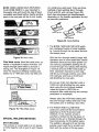
of a continuous weld bead. There are three
methods of spot welding: Burn-Through,
Punch and Fill, and Lap (see Figure 20).
Each has advantages and disadvantages
depending on the specific application as well
as personal preference.
PUNCH AND FILL
_
LAP SPOT
BURN THROUGH
Figure 20. Spot Welding
.
Figure
18. Butt Joints
i
Do not use 0.024 inch diameter solid or
0.030 inch self-shielding
fiux-core wires
when using the burn-through method
unless the metal is VERY thin or
excessive filler metal build-up and minimal
penetration is acceptable.
Lap Joint Welded
In Three Passes
_
__
li_,_
_
TJont n
Three Passes
Always select the HIGH heat setting with
the burn-through
method and tune in the
wire speed prior to making a spot weld.
(
,
Figure
SPECIAL
19. Fillet Weld Joints
WELDING
BURN-THROUGH
METHOD welds
overlapped pieces of metal together
burning through the top piece and into
bottom piece.
With the burn-through
method, larger wire
diameters tend to work better than smaller
diameters because they have greater current carrying capabilities allowing the arc
to burn through very quickly while leaving
a minimal amount of filler metal build up.
Wire diameters that tend to work best,
with the burn-through
method, are 0.030
inch diameter solid wire or 0.035 inch
self-shielding
flux-core wire.
Fillet Weld Joints. Most fillet weld joints, on
metals of moderate to heavy thickness, will
require multiple pass welds to produce a
strong joint. The illustrations in Figure 19
show the sequence of laying multiple pass
beads into a T fillet joint and a lap fillet joint.
I _
The
two
by
the
METHODS
SPOT WELDING
The purpose of a spot weld is to join pieces
of metal together with a spot of weld instead
20
The PUNCH AND FILL METHOD
produces a weld with the most finished
appearance
of the three spot weld
methods. In this method, a hole is
punched or drilled into the top piece of
metal and the arc is directed through the
hole to penetrate into the bottom piece.
The puddle is allowed to fill up the hole
leaving a spot weld that is smooth and
flush with the surface of the top piece.
Select the wire diameter, heat setting, and
tune in the wire speed as if you were
welding the same thickness material with
a continuous bead.
3. The LAP SPOT METHOD directs the
welding arc to penetrate the bottom and
top pieces, at the same time, right along
each side of the lap joint seam.
Select the wire diameter, heat setting, and
tune in the wire speed as if you were
welding the same thickness material with
a co_tinuous bead.
SPOT WELDING
INSTRUCTIONS
1. Select the wire diameter and heat setting
recommended
above for the method of
spot welding you intend to use.
2. Tune in the wire speed as if you were
going to make a continuous weld.
3. Hold the nozzle piece completely
perpendicular
to and about 1/4 inch off
the work piece.
4. Pull the trigger on the gun and release it
when it appears that the desired penetration has been achieved.
5. Make practice spot welds on scrap metal,
varying the length of time you hold the
trigger, until a desired spot weld is made.
6. Make spot welds on the actual work piece
at desired locations.
This welder has been engineered to give
many years of trouble-free service providing
that a few very simple steps are taken to
properly maintain it.
1. Keep the wire drive compartment
lid
closed at all times unless the wire needs
to be changed or the drive tension needs
adjusting.
2. Keep all consumables
(contact tips, nozzles, and gun liner) clean and replace
when nec_essary. See CONSUMABLE
MAINTEI_ANCE
and TROUBLESHOOTING later in this section for detailed
information.
3. Replace power cord, ground cable,
ground clamp, or gun assembly when
damaged or worn.
4. Periodically clean dust, dirt, grease, etc.
from your welder. Every six months, or as
necessary, remove the side panels from
the welder and air-blow any dust and dirt
that may have accumulated
inside the
welder.
I
f]WARNING
Electric shock can kill! To reduce the risk
of electric shock, always unplug the welder
from its ac power source before removing
side panels.
CONSUMABLE
MAINTENANCE
IT IS VERY IMPORTANT TO MAINTAIN THE
CONSUMABLES
TO AVOID THE NEED
FOR PREMATURE
REPLACEMENT
OF
THE GUN ASSEMBLY.
The GUN LINER is intended to provide an
unrestricted path for the welding wire to flow
through the gun assembly. Over time the
liner will accumulate dust, dirt, and other
debris. Replacement
is necessary when
these accumulations
begin to restrict the free
flow of wire through the gun assembly.
MAINTAINING
THE CONTACT TIP
The purpose of the CONTACT TIP is to
transfer welding current to the welding wire
while allowing the wire to pass through it
smoothly.
21
Always use a contact tip stamped with the
same diameter as the wire it will be used
with.
Note: Due to inherent variances in flux-cored
welding wire, it may be necessary to use a
contact tip one size larger than your flux core
wire if wire jams occur.
.
.
If the wire burns back into the tip, remove
the tip from the gun and clean the hole
running through it with an oxygen-acetylene torch tip cleaner or tip drill.
Over time, the hole in the contact tip will
become worn by the wire passing
through it. The more worn this hole
becomes, the less efficient is the transfer
of welding current to the wire and eventually arc breakage and difficult arc starting
will result. Replace contact tips when
signs of wear become apparent.
MAINTAINING
THE NOZZLE
The nozzle directs the shielding gas to the
weld puddle, determines the size of the
shielding area, and prevents the electrically
hot contact tip from contacting the work
piece.
CAUTION
\.
KEEP THE NOZZLE CLEAN! During the
welding process, spatter and slag will build
up inside the nozzle and must be cleaned
out periodically. Failure to clean and/or
replace the nozzle in a timely fashion WILL
CAUSE DAMAGE TO THE FRONT-END
OF
THE GUN ASSEMBLY.
For best results, coat the inside of a new, or
freshly cleaned nozzle with anti stick spray
or gel.
1. Stop welding and clean any accumulated
slag or spatter from the nozzle every 5 to
10 minutes of welding time.
2. When welding overhead, if any molten
metal drips from the weld puddle and
falls into the nozzle, STOP WELDING
IMMEDIATELY
and clean the nozzle.
3. If the slag cannot be thoroughly cleaned
from the nozzle, REPLACE THE
NOZZLE!
Failure to keep the nozzle adequately
cleaned can result in the following
problems:
22
A SHORTED nozzle results when spatter
buildup bridges the insulation in the nozzle,
allowing welding current to flow through it as
well as the contact tip. When shorted, a
nozzle will steal welding current from the
wire whenever it contacts the grounded work
piece. This causes erratic welds and reduced
penetration.
In addition, a shorted nozzle
overheats the end of the gun, which can
DAMAGE the front-end of the gun.
A RESTRICTED
nozzle is created when
enough slag builds up in the nozzle to affect
the direction, concentration,
and/or rate of
the shielding gas flow. This problem can
cause porous, brittle welds and reduce
penetration.
TESTING FOR A SHORTED NOZZLE
Arcing between the nozzle and the work
piece ALWAYS means the nozzle is shorted,
but this can be hard to detect through the
lens of a welding helmet. The following
testing method is another way to tell if a
nozzle is shorted.
With the welder unplugged from the ac
power source, touch the probes of an
ohmmeter or continuity tester to the end of
the contact tip and the outside of the nozzle.
If there is any continuity at all, the nozzle IS
shorted. Clean or replace as needed.
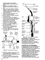
REPLACE A GUN LINER
When installing a new gun liner, care must be
taken not to kink or otherwise damage the gun
liner. See Figure 21 for the drive assembly
and Figure 22 for the gun assembly.
1. Turn OFF welder POWER SWITCH and
unplug welder from power supply.
2. Open the welder side panel.
3. Loosen the tension arm and lift it up off
the drive roller.
4.
5.
6.
Turn the wire spool counter-clockwise
(be
sure to hold onto the wire itself while
turning the spool or the wire will unspool
itself when it becomes free of the gun
liner), and remove wire from gun
assembly.
Lay gun cable and gun handle straight
out in front of unit.
Remove gun liner holding clamp by
removing two self tapping screws and
two bolts with nuts.
7. Take gun handle halves apart by removing five phillips head screws.
8. Remove liner from fast coupler fitting on
gas valve. Depress lip on fast coupler
back towards fitting and pull liner out.
9. Remove liner from outer torch sleeve and
pull out.
10. Remove fast coupler fitting from gas
valve.
11. Install new liner, starting from handle end
and feeding towards unit with fitting end
of I_ner going towards the gas valve.
12. Fitllner for length at feeder end by cutting liner with wire cutters.
13. Reinstall liner holding clamp at feeder.
14. Return all components to the handle
casing and realign them as they were
originally.
15. With both halves of the handle case in
place, tighten the five phillips head
screws.
16. Reinstall the welding wire according to
specifications
in INSTALL THE WELDING
WIRE section.
17. Close side panel.
18. Plug welder into power supply and turn
POWER SWITCH to ON position.
Drive
Tension
Adjustment
Drive
Gun
Tension
Arm
Assembly
(Tail
Nozzle
Contact Tip
Gas Diffuser
Conductor
Tube
Jbe
Insulation
Trigg
.
Live Wire
Gas Hose
Switch
Contacts
Gun
Liner
Handle
Casing
Switch
Switch
Wire
Wire
Gun
Cable
Figure 22. Gun Assembly
PREVENTIVE
MAINTENANCE
Except for internal and external cleaning,
cleaning the nozzle, and occasionally
retightening screws, there is no periodic
maintenance recommended
for your welder.
®
Inlet
Guide
Tube
Figure
Drive
Jn
Strain
Relief
Roller
Liner
Clamp
21. Drive Assembly
TROUBLESHOOTING
The following TROUBLESHOOTING
information is provided as a guide to help
resolve some of the more common problems
that could be encountered. Table 4 is a
troubleshooting
table provided to help you
determine a possible remedy when you are
having a problem with your welder. This table
does not provide all possible
solutions, only
those possibilities considered to likely be
common faults. The table consists of a
TROUBLE or symptom, a POSSIBLE
CAUSE for the symptom, and a POSSIBLE
REMEDY for that symptom.
23
POSSIBLE
TROUBLE
Dirty, porous, brittle weld
Wire feed works but no arc
1. Plugged welding nozzle
2. No shielding gas
3. Wrong type of gas
4. Dirty or rusty welding wire
ING gas section of manual•
4. Replace spool of wire.
1. Bad ground or loose
connection
1. Check ground and
connections• Tighten as
Arc works but not feeding wire 1. Faulty wire speed control
assembly
2. No tension on drive roller
3. Faulty drive motor (RARE!)
Low output or non_enetrating weld
1. Faulty trigger on gun
2. Exceeded duty cycle;
thermal protector opened
3. Faulty transformer (RARE!)
1. Loose connection inside
machine
2. Too tong or improper
extension cord
3. Wrong type or size wire
4. Poor ground connection
5. Wrong size contact tip
6. Loose gun connection or
faulty gun assembly
7. Wrong welding polarity set
8. Dirty or rusty welding wire
Wire is jamming or
"birdnesting" at the
drive roller
REMEDY
1, Clean or replace nozzle.
2. Tank empty, flow restricted
or regulator set too low.
3. See SELECTING SHIELD-
2. Bad connection to gun or
faulty gun
i Nothing works except fan
POSSIBLE
CAUSE
1. Too much tension on
drive roller
necessary.
2. Check connection to gun or
replace gun
1. Replace wire speed control
assembly.
2, Adjust the drive tension.
3. Replace drive motor.
• Replace gun trigger.
2• Let welder cool at least
10 minutes (observe and
maintain proper duty cycle.)
3. Replace transformer.
1• Blow inside of machine out
with compressed air. Clean
and tighten all connections.
2, See EXTENSION CORDS
section of manual.
3. Use correct size wire.
4• Reposition clamp and check
cable to clamp connection.
5• Use correct size contact tip.
6. "13ghtengun or replace gun.
7. Change to proper polarity.
8. Replace spool of wire•
: 1. Adjust drive tension• (See
INSTALL THE
WELDING WIRE)
2• Replace gun liner.
3. Replace contact tip.
2. Gun liner worn or damaged
3. Contact tip is clogged or
damaged
4. Liner stretched or is too tonc 4. Trim liner to proper length.
Wire burns back to contact tip
94
1•
2.
3•
4•
Ground clamp and/or
ground cable gets hot
Gun liner worn or damaged
Liner stretched or is too lone
Wrong size contact tip
Contact tip is clogged or
damaged
Bad connection from cable
to clamp
Gun nozzle arcs to work
surface
Slag buildup inside nozzle
or nozzle is shorted
1.
2.
3.
4.
Replace gun liner•
Trim liner to proper length•
Use correct size contact tip.
Replace contact tip.
Tighten connection or
replace cable•
Clean or replace nozzle
as needed.
_L,_'
pT( .f,pT
' PT( (PT
$3_- /
--1
6AS/NO GASCHANGE
eJ114
E__,F<..-'
_
ii
120V
60Hz
r--T-_
T1
(<
I
'$1[ _)
I i
il
I
[_-L.__.
i
K1
_.1
I
I
I
I
L._J
+®
I'_ _''"
"_1
I+<_----------',_ "1
E 0592
22710044
I -<_-----_:::::_
(......
i
£____.J
26
No.
Code
Description
Qty.
01
02
03
04
05
06
07
08
09
10
11
12
13
14
15
15a
16
17
18
19
20
21
22
23
23a
24
25
26
27
28
29
30
31
32
33
34
35
36
37
38
39
40
41
42
43
44
45
46
47
48
49
50
51
52
53
54
55
56
57
58
59
60
61
62
63
64
65
66
WE20569-21690175
WE20569-21690176
WE20569-21600021
WE20569-21610014
WE20569-21610015
WE20569-05000065
WE20569-33700138
WE20569-33715063
WE20569-33720063
WE20569-05000066
WE20569-05000067
WE20569-22200035
WE20569-22205117
WE20569-04600054
WE20569-04600002
WE20569-21800036
WE20569-22400021
WE20569-22210014
WE20569-44120087
WE20569-22225016
WE20569-44135001
WE20569-44400024
WE20569-22710044
WE20569-04600114
WE20569-21800051
WE20569-23000081
WE20569-21690244
WE20569-21605010
WE20569-20220018
WE20569-43210148
WE20569-22110025
WE20569-21690001
WE20569-216_1_310
WE20569-21690312
WE20569-22910070
WE20569-04600141
WE20569-33805001
WE20569-21010010
WE20569-21590002
WE20569-21020018
WE20569-21020006
WE20569-21020039
WE20569-21020038
WE20569-21020037
WE20569-21020018
WE20569-21030010
WE20569-21000005
WE20569-21035002
WE20569-21025029
WE20569-21030008
WE20569-21000020
WE20569-21035004
WE20569-21025028
WE20569-21030011
WE20569-21025011
WE20569-21020011
WE20569-21030002
WE20569-21025015
WE20569-21020003
WE20569-21005017
WE20569-21005040
WE20569-33810095
WE20569-21690177
WE20569-21055015
WE20569-77600316
WE20569-21905002
WE20569-21905007
WE20569-21905011
Front Plastic Frame
Back Plastic Frame
Plastic Hanlde
Front Plastic Foot
Back Plastic Foot
Front Panel
Lower Panel
Rear Panel
Dividing Panel
Right Upper Panel
Access Door
Yellow Power Switch 16A-250V
Switch 17A
Complete Fan
Complete Spool Holder
Spool Holder Handwheel
Rectifier PMS 30B F Type
Thermostat 100 ° 10A
Transformer 115V 40x60 AL
Contactor LX0 110V 10A4NA
Choke 40x40 AL
Black Plastic Wire Feeder
P.C. Board EO592.1R 110V + Fuse "CSA"
Kit Gas/No Gas Change Board
Handwheel 030
Gun 0/8 10mm =
Gun Pressure Cover
Cable Clamp For hole 020
Power Cable 3x4WG14 m 2.5
Ground Cable 10mm =
Ground Clamp 300A
Gun Grommet on Front Panel
Wire Speed Knob
Voltage Settings Knob
Bulkhead Connector Tube 04
Wire Feeding Motor
Wire Feed Roll e9x30.023-.030
Knurled
ST-CE Screw for Feed Roll
Hexagonal L Key
Self-Tapping Screw for Frame
Self-Tapping Screw for Thermostat
Self-Tapping Screw for Cabinet
Self-Tapping Screw for Cabinet
Self-Tapping Screw for Feet
Self-TappingScrew
for Trans.&Choke
Washer forTransformer
& Choke
TE Screw for Choke & Contactor
Gear Washer for Choke & Contactor
Hex Nut for Contactor
Washer for Contactor
TE Screw for Rectifier & Contactor
Gear Washer for Contactor Fixing
Hex Nut for Rectifier & Contactor
Washer for Rectifier
Hex Nut for Rectifier
Self-Tapping Screw for Fan
TCl Screw for Fan
Hex Nut for Spool Holder
Self-Tapping Screw for Pressure Cover
TCI Screw for Pressure Cover
Handle Screw
Iron Pin 05 for Access Door
Side Panel Clip
Lock Washer for Clip
Suggested Settings Label
Plastic Welding Mask
Dark Glass for Welding Mask
Hammer-Brush
1
1
1
1
1
1
1
1
1
1
1
1
1
1
1
1
1
1
1
1
1
1
1
1
2
1
1
2
1
1
1
1
1
1
1
1
1
1
1
8
2
10
14
4
8
8
5
7
11
4
6
8
6
4
1
2
2
1
2
2
2
2
1
1
1
1
1
1
WIRE FEED WELDER
MODEL 196.205690
3
PARTS DIAGRAM
59
4O
11
61
40
63
2
917
16
57
62
\
25
58
8
4O
38
7
4O
6
18
42
4 42
56
66J
65 j
27
15
I
21
34
35
41
,37
14
45
46
rF
g
T--
,,=,
8
25
55
5
41
58
52
16
17
30
39
23
41
47
50
51
31
47
,,=,
1,5
41
46
12
45
48
41
45
44
28
29
27
26
45
20
18
19
44
43
GO
04
No. Code
Description
Qty.
01
02
03
04
05
06
07
08a
08b
08c
09
10
11
12
13
14
15
16
17
18
19
Black Gun Handle
Red Trigger for Gun
Gun Gas Valve
Gun Neck
Thread Guide Wire Liner
Conductor Tube Insulation
Gas Diffuser
.024 (0.6mm) Contact Tip `=
.030 (0.8mm) Contact Tip ]
.040 (1.0mm) Contact Tip
Nozzle
Pin for Gun Trigger D.4x16ZN
Fast-On Contact 6.3x0.8
1
1
1
1
1
1
1
1
1
1
1
1
1
No-Gas Gun Contact Spring
Self Tapping Screw TCC 3.9xl 6
Fast Coupling Connector
04 M6x0.75
Stainless Wire Liner 1.4x4 Blue L=2500
Rubber Outer Sleeve D.17.5 + Hose L=2200
Rilsan Gas Hose e2x4 L=3200
Gas Neck w/Outside Liner and Difuser
Gun Gas Valve
1
5
1
1
1
1
1
1
WE20569-21690300
WE20569-21690301
WE20569-23005009
WE20569-23005145
WE20569-23005091
WE20569-23005090
WE20569-23005146
WE20569-23005018
WE20569-23005019
WE20569-23005020
WE20569-23005147
WE20569-33810090
WE20569-21200010
WE20569-33800009
WE20569-21020012
WE20569-22910001
WE20569-23005131
WE20569-30900022
WE20569-30900007
WE20569-23005148
WE20569-23005144
WIRE FEED WELDER
MODEL
196.205690
GUN
3
?
1
I
5
10
Z
11
1Z
29
0
SUGGESTED
I CRRFTSMRN°I
SETTINGS
FOR WELDER
Recommendations
only -yariations
in input power, welding position,
wire, and gas will affect
the weld characteristics:
Use the voltage setting and wire speed indicated as a starting point then adjust for var!_M,_ such as stick out, travel _%pe__,__,
.-_.--!d- =n_,_, _b_mnlin_ss of metal, etc.
w:l[_:q:t
_-_-l,]s. 11 _=_
PROCEDURE
WELDING
WIRE
GAS
24 gage
.024 in
.61mm
22 gage
.030 in
.76ram
--
GASLESS
OC (-)
.030 in (0.8 mm)
Flux-Core Wire
.024
in (0.6 mm)
Steel Wire
MIG
DC (+)
.030 in (0.8 mm)
Steel Wire
NONE
.I/_
--
jf_,
20 pge
.036 in
.91ram
16 gage
.048 in
1.2ram
16 gage
.060 in
1.Smm
--
mm
m
B/2
B/3
B/4
C25
(7s% Argon,
25% CO:)
A/4
A/5
AJ6
B/4
C/5
C02
B/3
B/4
C/3
C/4
C/5
B/3
B/4
C/3
(7s% Argo.,
25% CO=)
C02
14 gage
.075 in
1.9mm
12 gage
.105 in
2.6 men
10 gage
.135 in
3.4mm
3/1G in
5.0mm
D/4
DIS
D/6
m
C/3
Garantia Limitada de Craftsman ........ 31
Introduccibn
........................................
31
Resumen de Seguridad ...................... 32
Informaci6n de Seguridad .................. 32
Riesgos de Choque EI6ctrico ............ 33
Riesgos de Destello del Arco ............ 33
Riesgos de Incendio .......................... 34
Riesgos de Vapores .......................... 35
Riesgosde GasesComprimidos
y susEquipos....35
Informaci6n Adicional de Seguridad ..36
Espectf.icaciones
de la Soldadora
.... 37
Desc_ipci6n ........................................
37
Caractedsticas de Operaci6n ............ 37
Ciclo de Funcionamiento .................... 37
Protecci6n T_rmica Interna ................ 37
Conozca su Soldadora
...................... 38
Instalacibn de la Soldadora ................ 39
Conexi6n al Suministro EI6ctrico ...... 39
Electricidad Requerida ...................... 39
Conexi6n al Tomacorriente
................ 39
Cordones de Extensi6n ...................... 39
Ensamblaje de la Soldadora .............. 39
Desembalaje de la Soldadora ............ 39
Lista de Empaque ..............................
39
Ensamblaje de la Careta para Soldar ..40
Instalaci6n del Asa ............................
40
Instalaci6n de las Patas .................... 40
Selecci6n del Gas Protector .............. 40
Instalaci6n del Gas Protector ............ 41
Inspecci6n del Flujo de Gas .............. 41
Garantia limitada de Tres Afios de la Soldadora
Alineamiento
y Graduaci6ndelRodillo
deAvance ..42
Instalaci6n del Alambre Soldador ...... 42
Regulaci6n
dela Tensi6ndelAlambreSoldador....44
Cambio de Polaridad .......................... 44
Operacibn
............................................
45
Controles e Indicadores
.................... 45
Interrupter ........................................
45
Selector de Voltaje .......................... 45
ControldelaVelocidaddeAvancedelAlambre....45
Aprendiendo
a Soldar
...................... 45
Como Suje_ar la Pistola ...................... 45
T_cnicas pa-_ra_oldar ........................ 46
Desplazamiento
de la Pistola .......... 46
Tipos de Cordones de Soldadura ....47
Posiciones para Soldar .................... 47
Soldadura de Pasadas M61tiples .... 48
M6todos Especiales para Soldar .... 49
Soldadura de Puntos .................... 50
Mantenimiento
....................................
50
Mantenimiento
General ...................... 50
Mantenimiento
de Insumos ................ 50
Mantenimiento de la Punta de Contacto ..51
Mantenimiento
de la Boquilla ............ 51
Prueba de Cortocircuito en la Boquilla .... 51
Cambio del Forro de la Pistola .......... 51
Mantenimiento
Preventivo .................. 52
Diagn6stico de Problemas
................ 53
Diagrama de Cableado
...................... 54
Lista de Piezas ....................................
55
Graduaciones
Sugeridas .................... 59
Craftsman
Si cualquier parte de 6sta soldadora, excepto por la pistola o los cables, fallase debido a un defecto
de materiales o de fabricaci6n durante tres afios a partir de la fecha de compra, devolverla al
Centro de Reparaciones y Repuestos de Sears mas cercano y Sears la reparara sin costo alguno.
Sears reparara la pistola o los cables sin costo alguno s61o durante el pedodo de un afio a partir de
la fecha de compra. Esta garantia no cubre las piezas que se gastan como las puntas de contacto
o boquillas, que se consumen durante la operaci6n normal de la soldadura. Esta garantia se aplica
s61o cuando la unidad se usa en los Estados Unidos. Esta garantia otorga derechos especificos y
usted tambi_n podria tener otros derechos que varian de un Estado a otro.
Sears, Roebuck and Co., D/817WA,
Hoffman Estates, IL 60179
Este Manual del Usuario provee informaci6n especifica sobre la soldadora con alimentador de
alambre. Para disponer de toda la informaci6n
necesaria para soldar en forma segura y
eficiente, debe usarse con la Guia de Instrucciones
para Soldar. La informaci6n en este
manual se aplica a este modelo especifico de soldadora con alimentador de alambre y provee
instrucciones
para su armado, instalaci6n y su uso.
31
Todo artesano respeta las herramientas
con las
que trabaja. Sabe que las herramientas
representan afios de mejoras y desarrollo
constantes. Un verdadero artesano tambi6n
sabe que las herramientas
usan mal o se maltratan.
son peligrosas
si se
La lectura de este Manual del Operador antes
de usar la soldadora, permitir& hacer un trabajo
mejor y m&s seguro. Aprenda los usos y
limitaciones de la soldadora, asi como los
peligros relacionados con el trabajo de
soldadura.
Nota:
Los siguientes s[mbolos de alerta de
seguridad identifican mensajes de seguridad
importantes en este manual.
•
Cuando vea uno de estos simbolos que
se indican a continuaci6n, este alerta a la
posibilidad de lesiones personales y lea
cuidadosamente el mensaje que le sigue.
I
..!1
I
_l
Este simbolo indica riesgos de incendio
durante los pasos que siguen.
INFORMACION IMPORTANTE
DE SEGURIDAD
A continuaciSn se proveen pautas de seguridad
para ayudarle a operar su soldadora nueva
bajo las condiciones m_ls seguras posibles.
Cualquier equipo que use energia el_ctrica
puede ser potencialmente peligroso cuando no
se siguen o se desconocen las instrucciones
de seguridad y de manipulaciSn.
A continuaci6n se provee la informaciSn
necesaria para que el u_uario opere y use la
unidad en forma segura.
Un aviso de ADVERTENCIA precediendo un
paso de un procedimiento indica que el
siguiente paso podria lesionar a la persona si
es que no se cumplen con las precauciones de
seguridad apropiadas.
Un aviso de PRECAUCI(SN precediendo un
paso de un procedimiento indica que el
siguiente paso podria dafiar el equipo en uso.
Se puede usar una NOTA antes o despu6s de
un paso en un procedimiento para remarcar o
explicar algo propio de ese paso.
LEER TODAS LAS INSTRUCCIONES
DE
SEGURIDAD CUIDADOSAMENTE
antes de
intentar instalar, operar o darle servicio a esta
soldadora.
Ignorar estas instrucciones, podria
causar lesiones personales y/o dafios a la
propiedad.
CONSERVAR ESTAS INSTRUCCIONES
PARA REFERENCIA FUTURA.
32
descargas el6ctricas durante los
Este
indica riesgo de
pasossimbolo
que siguen.
Este simbolo indica que se debe usar
una careta para soldar durante los
pasos que siguen para proteger los
ojos contra riesgos de lesiones y
quemaduras por destellos.
Este simbolo indica que existe la
posibilidad de riesgos de gases
t6xicos durante la ejecuciSn de los
siguientes pasos.
,_]
Este simbolo indica que existe la
/ posibilidad de quemaduras por
escoria
caliente durante
de
los sigulentes
pasos. la ejecuci6n
Este simbolo indica que deben
usarse protectores de ojos para
proteger contra particulas
disparadas al aire en la ejecucion de
los siguientes pasos.
Este simbolo indica que existe la
posibilidad de lesiones o muerte por
la manipulaci6n o el mantenimiento
inadecuado de los cilindros de gas
comprimido o de los reguladores.
Existen publicaciones sobre normas de
seguridad. Estas se indican en la
informaciSn adicional de seguridad al final
de este resumen de seguridad.
El C6digo Electrico Nacional (EE.UU.), las
normas de la Ley de Salud y Seguridad
Ocupacional (OSHA), los cSdigos industriales
locales y los requisitos locales de inspecci6n
tambi6n sirven de base para la instalaci6n, uso
y servicio del equipo.
RIESGOS
DE CHOQUE
ELECTRICO
iLAS DESCARGAS ELI_CTRICAS PUEDEN
MATAR! Para reducir el riesgo de muerte o
lesiones serias por choques el_ctricos, se debe
leer, entender y acatar las siguientes
instrucciones de seguridad. Adicionalmente,
cerciorarse que todas las personas que operen
el equil_P de soldar y que est6n en el brea de la
soldad_a, tambi_n entiendan y acaten estas
rnedidas de seguridad.
• ilMPORTANTE! PARA REDUClR EL
RIESGO DE MUERTE, LESIONES O
DANOS A LA PROPIEDAD, NO INTENTAR
OPERAR este equipo de soldar hasta
haber leido y entendido el siguiente
resumen de seguridad.
• Bajo ning6n motivo hacer contacto fisico con
parle alguna de la soldadora durante el
circuito de corriente para soldar, que incluye:
a. La pieza de trabajo o cualquier material
conductor en contacto con _sta,
b. La pinza de conexi6n a tierra,
c. El electrodo o alambre de soldar,
d. Cualquier otra pieza met&lica en el
sujetador del electrodo o pistola
alimentadora de alambre.
• No soldar en un _rea h6meda ni entrar en
contacto con una superficie h6meda o
mojada.
• No intentar soldar si es que alguna parte de la
ropa o del cuerpo estuviese mojada.
• No permitir que el equipo de soldar entre en
contacto con agua o humedad.
• No arrastrar los cables soldadores, la pistola
alimentadora de alambre, ni el cord6n de
suministro el_ctrico de la soldadora. Tampoco
permitir que _stos entren en contacto con
agua o humedad.
• No tocar la soldadora, intentar encenderla o
apagarla si alguna parte del cuerpo o de la
ropa est_ hemeda o si usted est_l en contacto
ffsico con agua o humedad.
• No intentar enchufar la soldadora a un
suministro el_ctrico si alguna parte del cuerpo
o de su ropa est_ h6meda o si usted est_ en
contacto con agua o humedad.
• No conectar el sujetador ni soldar la pieza de
trabajo a un tubo conductor de electricidad.
• No alterar el cord6n de suministro electrico, ni
el enchufe en forma alguna.
• No intentar enchufar la soldadora a un
tomacorriente si la clavija para conexi6n a
tierra en el enchufe del cord6n estuviese
doblado, roto o faltante.
• No permitir que la soldadora se conecte a un
tomacordente, ni intentar soldar si la
soldadora, los cables para soldar, el lugar
donde se va a soldar o el cord6n de
suministro el6ctrico est&n expuestos en forma
alguna a precipitaci6n atmosferica,
salpicaduras o chorros de agua salada.
• No cargar los cables de soldadura enrollados
alrededor de_ hombro ni parle alguna del
cuerpo cuar_lo est6n enchufados a la
soldadora.
• No modificar el cableado, las conexiones a
tierra, interruptores ni fusibles del equipo de
soldar.
• Usar guantes de soldar para ayudar a aislar
las manos del circuito de soldadura.
• Mantener todos los envases con liquidos
alejados Io suficiente de la soldadora y de la
zona de trabajo, de modo que si el liquido se
derrama no tenga posibilidades de entrar en
contacto con parte alguna de la soldadora o
del circuito el6ctrico de soldar.
• Reemplazar INMEDIATAMENTE cualquier
pieza rajada o daSada que estuviese aislada o
sirvan de aislamiento, como los cables de
soldar, el cord6n de suministro electrico o el
sujetador de electrodos.
DESTELLOS
PELIGROSOS
ADVERTENClA
iLOS RAYOS DE LOS ARCOS PUEDEN
LESIONAR LOS OJOS Y QUEMAR LA PIEL!
Para evitar estos riesgos, se debe leer,
entender y acatar las siguientes instrucciones
de seguridad. Adicionalmente, cerciorarse que
todas las personas que operen el equipo de
soldar y que estdn en el _rea de la soldadura,
tambi_n entiendan y acaten estas medidas de
seguridad. La careta y la lente filtrante deben
cumplir con la Norma Z87.1 de ANSI.
• No rnirar a un arco electrico sin la
protecci6n adecuada.
• No mirar a un arco el6ctrico sin la protecci6n
adecuada.
• Un arco eldctrico es extremadamente
brillante y con protecci6n ocular adecuada o
sin ella, la retina puede quemarse
33
•
•
•
•
•
•
dejando una mancha negra permanente en
el campo de visi6n. Debe usarse una careta
con un lente oscuro No. 10 (minimo).
No encender el arco de soldar hasta que
todos los observadores y usted (el soldador)
tengan puesta su careta de soldar.
No usar cascos ni caretas rajadas o rotas, y
reemplazar inmediatamente los lentes
filtrantes.
No permitir que la parte no aislada de la
pistola alimentadora de alambre haga
contacto con la pinza de conexi6n a tierra o
la pieza de trabajo conectada a tierra para
evitar que se forme un arco al hacer
contacto.
Proveer caretas con lente filtrante No. 10 a
los observadores.
Usar ropa protectora. La luz intensa del arco
de soldadura puede quemar la piel de la
misma forma que el sol, alan a trav6s de ropa
liviana. Use ropa oscura de material pesado.
La camisa que se use debe ser de manga
larga y el cuello debe mantenerse abotonado
para proteger el pecho y el cuello.
Protecci6n contra los reflejos de los rayos del
arco. Los rayos del arco pueden reflejarse
en superficies brillantes como las superficies
con pintura brillante, de aluminio, acero
inoxidable y vidrio. Es posible que sus ojos
se lesionen por los reflejos de los rayos del
arco, at_n cuando se use careta protectora.
Si suelda con una su_icie
reflexiva atras
suyo, los rayos del arco pueden rebotar de la
superficie, luego de los lentes filtrantes al
costado de su careta y de ahi a sus ojos. Si
existe un fondo reflexivo en la zona del
trabajo de soldadura, saquelo o cubralo con
algo no inflamable y no reflexivo. Los rayos
que reflejan de los arcos tambi_n pueden
causar quemaduras de la piel, ademas de
lesiones a los ojos.
RIEGOS
DE INCENDIO
ADVERTENCIA
iLOS INCENDIOS O EXPLOSIONES
PUEDEN CAUSAR MUERTE, LESIONES Y
DANOS A LA PROPIEDAD!
Para evitar estos
riesgos, se debe leer, entender y acatar las
siguientes instrucciones de seguridad.
Adicionalmente, cerciorarse que todas las
personas que operen el equipo de soldar y que
esten en el &rea de la soldadura, tambien
entiendan y acaten estas medidas de
seguridad, iRECUERDE!
Porsu naturaleza,
34
los arcos de soldar producen chispas, gotean
metal derretido y escoria caliente y pedazos de
metal caliente que pueden iniciar incendios,
quemar la piel y lesionar los ojos.
• No usar guantes ni ropa que contenga aceite,
grasa u otras sustancias inflamables.
• No usar preparaciones inflamables en el
cabello.
• No soldar en un area hasta haber verificado
que no existan materiales combustibles y/o
inflamables. TENER EN CUENTA que las
chispas y la escoria puede volar 11 m (35') y
pasar por pequeSas rajaduras o aberturas.
Si su trabajo y los materiales combustibles
no pueden mantenerse separados un minimo
de 11 m (35'), protegerlos adecuadamente
para que no se enciendan, coloc&ndoles
cubiertas protectoras resistentes al fuego.
• No soldar en paredes hasta haber revisado
que no existan materiales combustibles
haciendo contacto al otro lado de las
paredes, y si las hubiese, sacarlas.
• No soldar, cortar, ni realizar trabajos similares
en tambores, cilindros, tanques, ni otros
contenedores que hayan contenido
substancias inflamables o t6xicas. Las
tecnicas para evacuar las sustancias y
vapores inflamables para que un contenedor
quede seguro para soldar o cortar, son
bastante complejas y requieren
entrenamiento y capacitaci6n especial
• No formar un arco el6ctrico en un cilindro de
gas o de aire comprimido, ni en contenedor
presurizado alguno; porque se creara un
area quebradiza que podria causar una
ruptura violenta inmediatamente o en el
futuro como consecuencia de una
manipulaci6n ruda.
• No soldar ni cortar en una zona donde el aire
pueda contener polvo inflamable (como polvo
de granos), gases, liquidos o vapores (como
de gasolina).
• No agarrar metales calientes como la pieza
de trabajo o los restos de electrodos con las
manos desnudas.
• Usar guantes de cuero, camisa gruesa de
manga larga, pantalones sin dobladillo o
basta, botines que cubran los pies hasta
arriba, casco, careta y capa.
• Seg_n fuese necesario, usar ropa protectora
adicional como saco con mangas de cuero,
polainas o mandil resistentes al fuego. Las
chispas o metales calientes pueden alojarse
en dobladillo de las mangas, la basta de los
pantalones o los bolsillos. Los pu_os y los
cuellos de las camisas deben mantenerse
abotonadas y se debe eliminar los bolsillos
del pecho de la camisa.
• iTener equipos extintores de incendio a mano
•
•
•
•
para uso inmediato! Se recomienda un extintor
port&til de quimico tipo ABC.
Cuando se suelde en posiciones por encima
de la cabeza, usar tapones de oidos para
evitar que las chispas o la escoria caliente
caigan dentro de los oidos.
Asegurarse que el _rea donde se suelda
tenga un piso bueno, s61ido y seguro,
preferiblemente de concrete o mamposteria,
sin Iosetas, alfombras ni otros materiales
inflamables.
Proteger las paredes, cielo raso, y los pisos
de materiales inflamables con cobertores
resist_entes al calor.
Ante_de abandonar el area donde se ha
soldado, revisar que no queden chispas,
metales o escoria caliente, ni llamas.
RIESGOS DE VAPORES
ADVERTENCIA
iLAS EMANACIONES, GASES Y VAPORES
PUEDEN CAUSAR INCOMODIDAD,
ENFERMEDAD O MUERTE! Para evitar estos
riesgos, se debe leer, entender y acatar las
siguientes instrucciones de seguridad.
Adicionalmente, cerciorarse que todas las
personas que operen el equipo de soldar y que
esten en el area de la soldadura, tambi6n
entiendan y acaten estas medidas de
seguridad.
• No soldar en un area si no hasta despues de
haber verificado que tenga ventilaci6n
adecuada segen Io descrito en la Norma
Z49.1 de ANSI. Si la ventilaci6n no es
adecuada para intercambiar los vapores y
gases generados durante el proceso de
soldadura con aire fresco, no soldar a
menos que usted (el soldador) y todas las
otras personas en el &rea de la soldadura
usen equipos respiradores autocontenidos.
• No calentar metales cubiertos con o que
contengan materiales que produzcan
vapores t6xicos (como acero galvanizado), a
menos que primero se saque el
recubrimiento.
Asegurarse que el area este
bien ventilada y que el operador y todas las
otras personas en el area de la soldadura
usen equipos respiradores autocontenidos.
• No soldar, cortar ni calentar plomo, zinc,
cadmio, mercurio, berilio, ni metales similares
sin asesoramiento profesional y sin haber
inspeccionado la ventilaci6n del area donde se
va a soldar. Estos metales producen vapores
EXTREMADAMENTE TOXICOS que pueden
causar incomodidad, enfermedad o muerte.
• No soldar ni cortar en areas donde existan
solventes clorinados. Los vapores de los
hidrocarbones clorinados tales come el
tricloroetileno y percloroetileno, pueden
descomponerse con el calor de un arco
electrico o su radiaci6n ultravioleta. Esto
puede generar fosgeno, un gas altamente
t6xico y otros gases irritantes de los ojos y los
pulmones. No soldar ni cortar cuando estos
vapores puedan ingresar al area de trabajo o
donde la radiaci6n ultravioleta pueda penetrar
alas _reas que contienen aunque sea
pequefias cantidades de esos vapores.
• No soldar ei_ url_rea confinada a menos que
este bien ventilada o el operador y todas las
otras personas en el &rea de la soldadura usen
equipos respiradores autocontenidos.
• Si se desarrolla una irritaci6n momentanea de
los ojos, nariz o garganta, deje de soldar
porque esto significa que la ventilaci6n no es
adecuada. Paralice el trabajo y tome las
medias necesarias para mejorar la ventilaci6n
en el area de la soldadura.
No reinicie la soldadura si la incomodidad
fisica persiste.
RIESGOS DE GASES COMPRIMIDOS
DE SUS EQUIPOS
Y
ADVERTENCIA
iLA MANIPULACION O EL MANTENIMIENTO
INADECUADO DE LOS CILINDROS DE G,_.S
COMPRIMIDO O DE LOS REGULADORES
PUEDE CAUSAR LESIONES SERIAS O
MUERTE!
Para reducir el riesgo de muerte o lesiones
serias por gases compdmidos o sus equipos,
leer, entender y seguir las siguientes
instrucciones de seguddad. Adicionalmente,
cerciorarse que todas las personas que operen
el equipo de soldar o que est6n en el _rea de
la soldadura, tambien entiendan y sigan estas
instrucciones de seguridad.
• No usar gases inflamables en
soldadoras MIG, s61o se deben usar
gases inertes o no inflamables como
por ejemplo di6xido de carbono, arg6n,
helio, etc. o mezclas de estos gases.
• No intentar mezclar gases ni rellenar los
cilindros usted mismo. No exponer los
cilindros a calor excesivo, chispas, escoda,
llamas, etc. Los cilindros expuestos a
temperaturas superiores a 54°C (130°F)
35
necesitan rociarse con agua para que se
enfrien.
• No exponer los cilindros a tipo alguno
de electricidad.
• No usar los cilindros o su contenido
para prop6sitos diferentes a los que
est&n indicados. No usar los cilindros
como soportes ni como rodillos.
• No colocar los cilindros en corredores ni
vias de transito donde los puedan golear
o tumbar.
• No usar Ilave para tuercas ni martillo
para abrir las valvulas de los cilindros
que no puedan abrirse a mano.
Comunicarse con el proveedor.
• No modificar ni intercambiar acoples,
valvulas, medidores, reguladores, etc.
entre cilindros de gases.
• No ocultar ni alterar el nombre, numero u
otras marcas identificadoras de los
cilindros. No confiarse en el color de los
cilindros para identificar su contenido.
• No conectar un regulador a un cilindro
conteniendo gas diferente a aquel para el
cual el regulador fue disefiado.
• No intentar reparar los reguladores,
enviar los que est6n defectuosos al centro
de servicios recomendado por su
fabricante para que Io reparen.
• No intentar lubricar los reguladores.
• Siempre cambiar los c[lindros
cuidadosamente para I_revenir las fugas
por dafios a sus paredes, v_lvulas o
dispositivos de seguridad.
• Siempre amarrar los cilindros con cadena
de acero para evitar que se tumben.
• Siempre proteger los cilindros,
especialmente sus v&lvulas, contra
golpes, cafdas, caida de objetos o el
clima. Recuerde que los gases dentro de
los cilindros est&n presurizados y que un
dafio a un regulador o a una de sus
partes puede hacer que salga
explosionado o disparado del cilindro
como un proyectil.
• Siempre mantener las tapas aseguradas
en los cilindros cuando se muevan.
• Siempre cerrar la v_lvula y sacar de
inmediato el regulador defectuoso para
que Io reparen si se presenta alguna de
las siguientes condiciones.
• Fugas del gas.
• La presi6n de salida sigue aumentando
cuando la v&lvula corriente abajo esta
cerrada.
• La aguja indicadora del medidor no se
mueve de la posici6n '_/acio/Parada"
aunque el cilindro est_ presurizado o no
regresa a "Vacio/Parada" despu_s de
despresurizarse.
36
INFORMACION ADICIONAL
DE SEGURIDAD
Para informaci6n adicional referente a la
seguridad para soldar, referirse alas siguientes
Normas y cumpla con Io que sea aplicable.
• Norma Z49.1 de ANSI-Seguridad para Soldar
y Cortar: Se puede obtener en la Sociedad
Americana de Soldadura, 550 NW Le Jeune,
Miami, FL. 33126, tel6fono (800) 443-9353,
fax (305) 443-7559;
www.amweld.org o www.aws.org
• Norma Z87.1 de ANSI, Pr_cticas Seguras
para el Trabajo y Educaci6n para la
Protecci6n de los Ojos y la Cara:
Se puede obtener en el Instituto Nacional
Americano de Normas,
11 West 42nd Street, New York,
New York 10036,
tel6fono (212) 642-4900,
fax (212) 398-0023, www.ansi.org
• Norma 51B NFPA, Proceso de Corte y
Soldadura: Se puede obtener en la
Asociaci6n Nacional de Protecci6n Contra
Incendios, 1 Batterymarch Park,
P.O. Box 9101, Quince, Ma. 02269-9101,
tel6fono (617) 770-3000,
fax (617) 770-0700, www.nfpa.org
• Norma 29CFR de OSHA, parte 1910,
Seccion Q, Soldadura, Corte y Soldadura
Fuerte: Se puede obtener en la oficina de
OSHA en su estado, o en la Secretaria de
Trabajo de EE.UU.
Oficina de Relaciones Publicas,
Room N3847, 200 Constituci6n Ave.,
Washington D.C. 20210,
www.osha.gov
• Norma W117.2 de CSA, C6digo de
Seguridad para Soldar y Cortar:
Puede obtenerse de la Asociaci6n
Canadiense de Normas,
178 Rexdale Boulevard,
Etobicoke, Ontario, M9W 1R3,
www.csa.ca
• Norma A6.0 de la Asociaci6n Americana de
Soldadura - Soldadura y Corte de
Contenedores que han Contenido
Combustible:
Se puede obtener de la Sociedad
Americana de Soldadura,
550 NW Le Jeune Road,
Miami, FL 33126,
telefono (800) 443-9353,
fax (305) 443-7759,
www.amweld.org
o www.aws.orgdard
DESCRIPCI(_N
Su nueva soldadora MIG (Gas Inerte al Metal) con
alimentador de alambre est& disehada para
trabajos de mantenimiento y fabricaciones con
soldadura de planchas met_licas. La soldadora se
compone de un transformador, estabilizador y
rectificador de corriente de una fase y
alimentador/controlador de alambre soldador
integrado de diseSo exclusivo. Ahora ya puede
soldar I&minas de metal calibre 24 y hasta de
4,8mrn_3/16") de espesor con una sola pasada.
Puede-soldar acero de mayor espesor con t6cnicas
de biselado y de pasadas m61tiples.
La Tabla 1 muestra las especificaciones de su
soldadora MIG con alimentador de alambre.
La soldadora tiene un ciclo nominal de
trabajo de 40% con la salida especificada.
Esto significa que se puede soldar por
cuatro (4) minutos de cada ciclo de
funcionamiento
de 10 minutos, requiriendo
los otros seis (6) minutos para enfriamiento.
(Ver la Tabla 2.)
Tabla 2. Ciclos de funcionamiento
J
Porcentaje
de trabajo
del Ciclo
•
_empo
Nominal
de Soldadura
Tiempo de
Descanso
Requerido
20%
2 minutos
8 minutos
60%
80%
100%
6 minutos
8 minutos
10 minutos
4 minutos
2 minutos
0 minutos
Tabla 1. Especificaciones de la soldadora
Entrada pdmaria
Entrada primaria
Fases
Frecuencia
Voltaje secundario de salida
Amperajesecundariode salidaUL
Voltaje Max. de circuito abierto
Ciclo de funcionamiento
120 VCA
13 Amps.
Una
60 Hz
21 V
85 Amps.
30 VCD
40%
Las soldadoras MIG equipadas con gas pueden
usar alambre de acero macizo de 0,6mm (0,024") y
0,8mm (0.030") con polaridad invertida en corriente
directa, y alambre de acero con n6cleo fundente
autoprotegido de 0,8mm (0,030") con polaridad
directa de corriente directa. Con esta soldadora
tambien se puede usar alambre mas grueso, de
0,9mm (0,035") que puede ser alambre de acero
macizo con polaridad inversa de corriente directa o
alambre de acero con nt)cleo fundente con
polaridad directa de corriente directa. El uso de un
alambre de di&metro mayor dificultara el trabajo de
soldadura y no se pueden garantizar buenos
resultados. El fabricante no recomienda el uso de
alambre de di&metro mayor a 0,9mm (0,035").
CARACTERISTICAS DE OPERACION
DE LA SOLDADORA
CICLO DE FUNCIONAMIENTO
El ciclo nominal de trabajo de la soldadora se
define como el tiempo que el operador puede
soldar en relaci6n al tiempo que debe dejarse
enfriar. El cicIo de trabajo se expresa como un
porcentaje de un periodo de 10 minutos y
representa el tiempo maximo de soldadura
continua permitida. Se requiere el saldo de los
10 minutos para enfriamiento.
PROTECCION
TI_RMICA
INTERNA
PRECAUCION
No exceder constantemente
del ciclo
nominal de trabajo porque se podria daSar
esta soldadora.
Si se excede el ciclo
nominal de trabajo de la soldadora, un
interruptor termico inferno se abrir_ para
interrumpir todas las funciones de la
soldadora excepto el ventilador de
enfriamiento.
Si ocurre esto, NO APAGUE
LA SOLDADORA,
dejela encendida para que
el ventilador siga funcionando.
Despu6s de
enfriarse, el protector t6rmico se reactivar&
autom&ticamente
y la soldadora funcionar&
normalmente
otra vez. Sin embargo, se
debe esperar por Io menos 10 minutos
despu6s que el protector t6rmico se abra,
para poder reanudar el trabajo de soldar.
Debe hacerse esto incluso si el protector
t6rmico se restablece autom&ticamente
antes de los 10 minutos, o la soldadora
rendira menos del ciclo de trabajo
especificado.
Si se observa que la soldadora no suelda
per dos minutos sin tener que parar, reducir
levemente la velocidad del alambre y afinar
a la velocidad minima que a6n produzca un
arco bien formado. Soldar con una velocidad
excesivamente
alta consume demasiada
corriente el_ctrica y acorta el ciclo de
trabajo.
37
Asa
Vel.de Alim.del alambre
Cablede lapistola
Selector
de voltaje
Interruptor:
Enciende (ON) y apaga (OFF).
(Cerciorarse que el interruptor est6 en la posici6n
de apagado (OFF) antes de realizar cualquier
mantenimiento a la soldadora).
Cordbn de Suministro El_ctrico:
Es un cord6n est&ndar de 120 voltios con
conexi6n a tierra. (Asegurarse de usar un
tomacorfiente de 120 VCA, 60 Hz, monof_sico de
20 amperios).
Pinza para Conexi6n a Tierra: Su conexi6n a la
pieza de trabajo "completa" del cimuito de
cordente para soldar de la soldadora; de Io
contrario no ser_ posible soldar Una mala
conexi6n de la pinza de conexibn a tierra hara
perder corriente y calor. Raspe la suciedad, 6xido,
sarro, aceite o pintura antes de conectar la pinza.
I
Pinza
Pistola
soldadora
Cablepara paratierra
tierra
Figura 1. Soldadora
Cable de Conexibn a Tierra: Conecta la pinza a
la parte intema de la soldadora.
Cord6n de
suministrOelectrico
Modelo 20569
Asa: Robusta, montada encima para facilitar el
transporte de la soldadora_.
Control de Velocidad del Alambre Soldador:
Usar este dial para regular la velocidad a la cual la
soldadora alimenta el alambre a la pistola. 1 es la
velocidad mas lenta y 10 es la velocidad mas
rapida. Se tendr_ que regular o "afinar" la
velocidad del alambre para las diferentes
condiciones de soldadura (espesor de los
metales, soldadura con gas vs sin gas, tipo de
metal, tamafios del alambre, etc.) Cuando se
Iogre afinar la velocidad, el alambre de soldar se
fusionara en el material que se esta soldando tan
pronto como pase por la pistola soldadora.
Selector de Voltaje: Este selector de cuatro
posiciones regula el voltaje o "calor" de la
soldadora. "A" es el minimo y "D" es el
m&ximo. Los materiales de diferente espesor
requieren diferentes graduaciones de voltaje.
Se necesita regular el voltaje de acuerdo alas
condiciones diferentes de soldadura.
Regulando adecuadamente el voltaje y la
velocidad de alimentaci6n del alambre se
pueden hacer soldaduras limpias y precisas.
(Referirse a la Tabla de Regulaciones
Sugeridas en ia pagina 30 de 6ste manual o en
el interior de la puerta de la soldadora).
38
Pistola Soldadora y Cable: La pistola soldadora
controla el paso del alambre de soldar al material
que se suelda. El alambre de soldar se alimenta
a traves del cable soldador y de la pistola
soldadora cuando se aprieta el gatillo de la pistola.
Antes de comenzar a soldar se necesita instalar
una punta de contacto y una boquilla de soldar en
el extremo de la pistola soldadora como se
describe m_s adelante en este manual.
T_rminos Propios de la Soldadura: Ahora que
se ha familiarizado con las partes principales de la
soldadora, tome nota de los siguientes t_rminos.
Los vera a Io largo de 6ste manual.
Charco de soldadura fundida
(Weld puddle): Un volumen de metal de
soldadura fundido antes que se solidifique.
Angulo de Soldar: El angulo en que el alambre
de soldadura se extiende de la pistola soldadora a
la pieza que se esta soldando.
Escoria (Slag): La capa protectora que se forma
en la superficiede los metales fundidos.
Arco: Una descarga luminosa o rayo sostenido
de electricidad a traves de una brecha en un
circuito.
Cordbn de Soldadura: La acumulaci6n
continuada extendida de soldadura que se forma
empujando o jalando el metal de
aporte fundido.
CONEXll _NAL SUMINISTRO
ELECTRICO
REQUISITOS DE CORRIENTE
Esta soldadora est_ disefiada para operar con
corriente altema (CA) monof_sica de 120 volUos,60 Hz
y fusiblede 20 amperioscon retardoo interruptor
de
circuito. Se recomiendaque un electricistacapacitado
verifiqueel VOLTAJEREAL en el tomacorrientedonde
se va a conectar lasoldadorapara confirmarque est_
debidamente protegidocon un fusible y conectado a
tierra. E_usode un circuitode la capacidadadecuada
elimina_ las molestias de aberturade losinte_ptores
de circuitocuandose est6soldando.
NO OPERAR ESTA SOLDADORA si el voltajeREAL
del suministro es menor de 105VCA o mayor de
132VCA. Comuniquese con un electricista calificado si
es que este problema existe. La soldadora funcionar_
inadecuada-mente y/o se daSar&si es que se opera
con un suministro electrico inadecuado o excesivo.
CONEXION
I
AL TOMA CORRIENTE
IADvERTENCIA
iPeligro de alto voltaje del tomacorriente!
Consultar a un electricista calificado para la
instalacibn de un tomacorriente adecuado a la
fuente electrica. Para proteger al operador
contra choques el_ctricos, esta soldadora debe
estar conectada a tierra mientras est_ en uso.
Si no se tuviese la seguridad de que el
tomacorriente este adecuadamente conectado a
tierra, hacerlo revisar por un electricista
calificado. No cortar, doblar ni alterar el
enchufe en forma alguna, ni usar tipo alguno de
adaptador entre el enchufe de la soldadora y el
tomacorriente. Cerciorarse que la soldadora
est_ con el interruptor en OFF (apagado) antes
de conectarla a un tomacorriente adecuado de
120 VCA, 60Hz, monof_sico.
CORDONES DE EXTENSION
Para el rendimiento 6ptimo de la soldadora, no
se deben usar cordones de extensi6n a
menos que sea absolutamente
necesario. Si
este fuese el caso, tener cuidado de
seleccionar el cord6n de extensi6n adecuado
para ta soldadora espec(flca en uso.
Seleccionar un cord6n de extensi6n que
conecte debidamente
a tierra directamente
en el tomacorriente
yen el enchufe de la
soldadora sin usar adaptadores.
Cerciorarse
que el cord6n de extensibn sea de los
alambres adecuados y que este en buenas
condiciones el6ctricas.
Los cordones de
extensi6n
deben tener alambres Cal. 12
como minimo y no deben exceder de 7,6m
(25') de largo.
ENSAMBLAJE
DE LA SOLDADORA
El siguiente procedimiento describe el
proceso para ensamblar, instalar, mantener
prepararse para soldar con la nueva
soldadora coj1 alimentador de alambre.
y
OESEMBAOE
,J so,oAOO
1.
2.
3.
Extraer todas las cajas o bolsas que
contengan piezas o accesorios.
(La
mayoria de las piezas se embarcan
dentro de la soldadora, abrir la
puerta.)
Abrir las cajas o bolsas de embalaje e
inspeccionar que su contenido no
haya sufrido da_os.
Disponer las piezas sobre una
superficie y compararlas contra la lista
de embalaje en la Tabla 3 para
familiarizarse
con elias y saber como
se les denomina.
Esto ayudara
cuando se lea el manual.
LISTA DE CONTENIDO
La Tabla 3 Contiene una lista de las piezas
que se encontraran en la caja.
Tabla 3 - Lista de Embalaje
Pieza
Cantidad
Soldadora
1
Careta para Soldar
1
Mango de la Careta para Soldar 1
Lente Oscuro
1
Asa de la Soldadora
1
Tornillo para el Asa
2
Pata Delantera y Posterior
1 c/u
Tornillos para Patas
4
Cepillo de Alambre/Martillo
1
Bolsa con Piezas
1
Punta de Contacto 0,024"
5
Punta de Contacto 0,030"
5
Punta de Contacto 0,040"
5
Boquilla
2
Alambre Flux-Core 0,030"
227gr (1/2 Lb)
Manual de Instrucciones
1
39
ENSAMBLAJE
DE LA
CARETA PARA SOLDAR
1. Quitar la u_as retenedoras de la lente y
la tuerca del mango del brazo de la
careta. (iNO DESECHARLOS!)
2. Colocar la lente oscuro en el espacio
provisto en la careta.
3. Insertar los tomillos sujetaclores de la lente
en los odficios a ambos lados de la lente
hasta que ajusten contra la lente,
4. Insertarla punta roscadadel mango en el
orificiode la careta. Presionarfirmemente hasta
que las roscas de la puntay la punta m_s
peque5a de abajo se enganchen en posici6n.
5. Desde el lado de dentro de la careta,
enroscar la tuerca del mango firmemente
en la punta. Parael ensamblajede lacareta,
Ver laFigura2
4.
5.
6.
Ajustar ambos tomUlos firmemente con
un desarmador con punta en cruz.
Alinear los orificios de las patas postedores con los orificios en la parte posterior
inferior de la soldadora. La cara curva de
las patas posteriores deben mirar hacia
afuera (atras) de la soldadora.
Insertar los dos tornillos con cabeza en
cruz (incluidos en la bolsa de piezas) en
los orificios.
I
!
Figu_ra 4. Instalaci6n de I_aspatas
,
Figura 2. Ensamblaje de la careta
INSTALACIC)N
DEL ASA
1. Insertar las pestaSas del asa en las
ranuras que estan encime.de la soldadora.
2. Insertar un tornillo grande de ranura recta
(incluido en la bolsa de accesorios) en
cada orificio del asa de la soldadora.
1
I!
1
I
Figura 3. Instalaci6n del Asa
3. Ajustar firmemente ambos tornillos con un
desarmador de punta plana. (Ver Figura 3)
INSTALACII_N
DE LAS PATAS
Ubicar las dos patas pl_sticas negras para la
soldadora. (Las patas frontales son
ligerarnente rn_s largas que las posteriores).
1. Echar la soldadora sobre su costado.
2. Alinear los orificiosde las paras frontales con
los orificios en la parte inferior de la
soldadora. La cara curva de las patas
frontales cleben mirar hacia afuera (frente)
de la soldaclora.
3. Insertar los dos tomillos con cabeza en cruz
(incluidos en la bolsa de piezas) en los
orificios.
40
Ajustar ambos tomillos firmemonte con
un desarrnador con punta en cruz.
(Ver la Fig. 4)
SELECClON
DEL GAS
PROTECTOR
El gas protector juega un papel importante en et
proceso de soldadura MIG Es critico que el
charco de soldadura fundida este protegido de la
atm6sfera. El gas auto-protegido crea una capa
protectora alrededor del charco de soldadura
fundida para impedir que las impurezas del aire Io
contaminen. Una protecci6n inadecuada dar_
como resultado una solcladura porosa o
quebradiza.
No obstante que existen muchos gases y muchas
mezclas de gases para soldadura MIG, las
siguientes recomendaciones se hacen basadas
en las caracteristicas de la salida de corriente de
esta soldadora MIG y su capacidad para soldar
los diversos espesores de metales.
Seleccibn del gas para soldar con alambre
de acero
Ya sea para acero blando o bajo en carb6n
(estructuralde gran fuerza) usar una mezcla de
gas de 75% de arg6n y 25% de di6xido de
carbono. NO USAR una concentraci6n de arg6n
superior a175% para el acero porque la soldadura
tendrQ extremadamente poca penetraci6n, serQ
porosa y quebradiza.
La mezcla de gas ayuda a prevenir las
quemaduras y distorsiones en acero muy delgado
a la vez que provee buena penetraci6n en el
acero mas grueso. Su capacidad para evitar
salpicaduras da como resultado una soldadura
limpia, pareja y de buena apariencia.
Adicionalmente, provee buen control del charco
de soldadurafundida paracuandose sueldaen
superficiesverticaleso elevadassuspendidas.
Seleccion del Gas para Soldar Acero Inoxidable
El mejor gas auto protegidopara soldar acero
inoxidable es una mezcla de 90% de helio con 7,5%
de arg6n y 2,5% de di6xidode carbono. Sin
embargo,tambien se puede usar 100% de arg6n;
pero aumentara el _rea de calentamientopor el
arco, creando una distorsi6nlevementemayoren el
metalbase.
Selec_bn del Gas para Soldar Acero corl
Alambre de Silicio y Bronce
S61o u-sararg6n puro cuando se suelde con
alambre de silicio y bronce.
INSTALACI6N
DEL GAS PROTECTOR
ADVERTENCIA
iLA MANIPULACI6N O EL MANTENIMIENTO
INADECUADO DE LOS CILINDROS DE GAS
COMPRIMIDO O DE LOS REGULADORES
PUEDE CAUSAR LESIONES SERIAS O
MUERTE! Siempre fljar los cilindros de gas
contra la carretilla de la soldadora, una pared o un
soporte fijo para evitar que se caigan y se
rompan. Leer, entender y seguir todas las
instruccionespara evitar RIESGOS DE GASES
COMPRIMIDOS Y EQUIPO RELACIONADO en
el RESUMEN DE SEGURIDAD al principiode
este manual. Fijar el cilindrode gas a la carretilla
de la soldadora o a alg6n otro soporte fijo.
1.
2.
3.
4.
5.
Quitar la tapa protectora del cilindro y revisar
las roscas de conexi6n del regulador y limpiar
el polvo, aceite o grasa con un paso limpio.
NO INSTALAR EL REGULADOR SI TIENE
ACEITE, GRASA O DANOS.
Abrir la v_lvula del cilindro POR UN
INSTANTE para expulsar cualquier matedal
extraSo que se encuentre en el orificio de la
v&lvula. Nunca apuntar la descarga de la
v_lvula hacia usted ni a otras personas.
Enroscar el regulador en la v_lvula del
cilindro y ajustarla con una Ilave.
Insertar la manguera de gas firmemente
en el conector arponado en la parte
posterior de la soldadora y del regulador.
Asegurar ambos extremos de la
manguera a los conectores arponados
con abrazaderas
para manguera.
VERIFICACI(_N DEL FLUJO DE GAS
ADVERTENCIA
iLA MANIPULACI(_N O EL MANTENIMIENTO
INADECUADO DE LOS CILINDROS DE GAS
COMPRIMIDO O DE LOS REGULADORES
PUEDE CAUSAR LESlONES SERIAS O
MUERTE!
Para reducir el riesg0 de lesi6n o
muerte, siempre pararse del lado contrado al
regulador cuando abra la valvula del cilindro,
manteniendo_ vatvula del cilindro entre usted y
regulador. Nunca apunte la descarga de la
v&lvula del cilindro a usted u otras persona. Si no
toma esta precauci6n podda causar lesiones
graves.
Nota: Si el cilindro que est& equipado con
un regulador con conector macho en vez de
hembra, conseguir un adaptador especial
para cilindros de gas donde su proveedor de
gas, para instalarlo entre el cilindro de gas y
el regulador.
- La funci6n de control del gas no
requiere que la soldadora este
encendida ni enchufada al
tomacorriente.
- Para evitar daSos al regulador,
cerciorarse que la v_lvula del regulador
este cerrada antes de abrir la v_lvula
del cilindro.
1. Abrir la valvula del cilindro muy levemente
y luego abrirla COMPLETAMENTE.
2. Apretar el gatillo de la pistola para permitir
que el gas fluya. MANTENER EL GATILLO
APRETADO, escuchar y observar si el gas
sale por la pistola soldadora. Si el
regulador es fijo, viene preajustado de
f&brica para un flujo de 566 L/hora (20
Pies3/hora). Si el regulador permitiese
controlar el flujo de gas, girar!o en el
sentido del reloj para aumentar el flujo y
contra el sentido del reloj para disminuirlo.
Para la mayorfa de soldaduras el flujo de
gas debe graduarse entre de 425 a 566
L/hora (15 a 20 Pies_/hora). Si no se oye o
se siente el gas, repasar todos los pasos
seguidos para conectar el gas.
3. Soltar el gatillo.
Nota: Siesta soldando a la intempede o donde haya
corrientes de aire, puede ser necesario colocar una
barrera contra el viento para evitar que el gas
protector se disperse y se aleje del _rea de soldar.
41
-RECUERDE
CERRAR LA VALVULA
DEL CILINDRO DE GAS CUANDO
TERMINE DE SOLDAR.
S_
_
ALINEAMIENTO
Y REGULACI()N DEL
RODILLO DE AVANCE
Antes de instalarcualquieralambre soldadoren
la unidad,debe colocarla ranura del tamafio
adecuado en posici6nen el mecanismo de
avance del alambre.
Cambiar el rodillo de avance de acuerdo a los
siguientes pasos:
1. Aliviar la tensi6n de avance desenroscand()
COMPLETAMENTE
(contra el sentido del
reloj) el tornillo tensor hasta soltarlo y
permitiendo tirar del brazo tensor para
separarlo del rodillo de avance. AsegQrese
de mantener el tomillo y el resorte en su
lugar con el brazo tensor.
2. Si hay alambre instalado en la soldadora,
enrollarlo manualmente de vuelta a su
carrete girando el carrete contra el sentido
del reloj. Tener cuidado de no permitir que
el alambre salga por atr&s de la pistola sin
sujetarlo, porque se desenrollara solo. Para
mantener el alambre enrollado, insertar la
punta del alambre por el agujero del borde
exterior del carrete y_doblarlo. Sacar el
carrete de alambre de la soldadora.
3. Aflojar el tornillo de fijaci6n del rodillo de
avance con la Ilave hexagonal provista y
sacarlo de su eje.
Nota: El rodillo de avance tiene dos ranuras
de diferente tamafio para alimentar alambres
de distinto di_metro. AI instalar el rodillo de
avarice, el nQmero estampado que
corresponde al calibre del alambre que va a
usar debe quedar en direcci6n opuesta a
usted. Si despues de colocarse puede leer el
calibre estampado del alambre, el rodillo
esta instalado al reves. Usar solamente
rodillos de avance del tamafio adecuado
para la soldadora.
.
42
Busque el lado del rodillo que est_l
estampado con el mismo diametro que el
alambre que se va a instalar (ver la Figura
5 y si usa unidades m6tricas, ver la
descripci6n).
Presionar el rodUlo de
avance en el eje del motor alineando el
tornillo de fijaci6n con el lado piano del eje.
Asegurarse que el lado estampado con el
nQmero del diametro del alambre
deseado no quede hacia usted.
R_'di_l°c_e
el Motor
Figura
5.
6.
5. Rodollo de Avance
Deslizar el rodillo en el eje con la ranura
del rodillo alineada con el tubo de entrada
del tubo y el forro de la pistola soldadora.
Ajustar el tomillo de fijaci6n a la vez que se
sujeta el rodillo de avance en su lugar.
INSTALACION
SOLDADOR
DEL ALAMBRE
Siempre apagar la soldadora poniendo el
interruptor en la posici6n "OFF" y
desenchufar del tomacorriente
antes de
instalar el alambre.
Tener mucho cuidado al sacar la boquilla
soldadora.
La punta de contacto de esta
soldadora se mantiene caliente
el_ctricamente
mientras que la soldadora
este encendida.
Asegurarse de apagarla.
1.
2.
3.
4.
Sacar la boquilla y la punta de
contacto del extremo de la pistola
soldadora.
Quitarle la tapa al carrete.
Desenrollar el alambre del carrete y
encontrar su extremo (pasa por el
orificio en el borde exterior del carrete
y est_ doblado para evitar que el
alambre de desenrolle). PERO NO
DESENGANCHARLO
AUN.
Colocar el carrete en el eje de modo
que el alambre al salir del carrete quede
como en la ilustraci6n superior en la
Figura 6. El alambre soldador siempre
debe salir por encima del carrete y entrar
en el mecanismo de avance.
Nota: Si se aplica DEMASIADA tensi6n al
carrete, el alambre resbalar_ en el rodillo de
avance o no podr& alimentarse. Si hay MUY
POCA tensi6n, el carrete de alambre tender&
a desenrollarse solo. Regular la tensi6n del
freno seg0n sea necesario para evitar estos
problemas.
7.
.
Si se est& instalando un carrete de
alambre de 10cm (4"), instalar el
mecanismo del freno sobre el carrete
como en la Figura 7A; pero si se instala
un carrete de 20 cm (8"), instalar un
adaptador de eje y el mecanismo de
freno como en la Figura 7B. El prop6sito
del freno es detener el giro del carrete
casi al mismo tiempo que se interrumpe
la alimentaci6n del alambre.
Despues de verificar que la soldadora
est6 desconectada
del tomacorriente,
destrabar la punta de alambre del
carrete, pero no la suelte hasta que se
le indiqueporque
el alambre
desenroll_r& "solo.
8. Usando una tenaza cortadora, cortar
la punta doblada para que el alambre
quede recto.
9. Aflojar el tornillo tensor sujetando el
brazo tensor del mecanismo de
avance en su lugar y levant&ndolo
para sacarlo del rodillo.
10. Insertar la punta del alambre por el
tubo guia de entrada y empujarlo
pasando el rodillo de avance y hasta
que entre unos 15 cm. (6") en la
pistola soldadora.
PRECAUCI()N
Aseg0rese que el alambre de soldar entre
realmente por el forro de la pistola y que no
haya entrado accidentalmente
a Io largo del
forro o en otra direcci6n. Si esto sucede, el
alambre podria alimentarse hacia adentro de
la cubierta del cable o podr[a tomar un
&ngulo recto y seguir por los cables o por la
manguera de gas, dentro de la soldadora.
Tambien podria retroalimentarse
atorando el
mecanismo.
Figura 7A.
Instalaci6n del
mecanismo
del freno
,
Figura 7B.
Instalaci6n del
adaptador para el
eje y del mecanismo
del freno
Una vez instalado el freno, regular la
tension del carrete de alambre girfindolo
con una mano mientras se regula la
tensi6n del carrete con la mano libre,
ajustando (en el sentido del reloj) la
perilla que sujeta el carrete en posici6n.
Dejar de apretar cuando se sienta que el
alambre del carrete deje de girar.
11. Alinear el alambre con la ranura interior
del rodillo de avance y dejar que el brazo
tensor caiga sobre el rodillo de avance.
12. Ajustar el tornillo tensor (en el sentido
del reloj) hasta que el rodillo haga
suficiente presi6n sobre el alambre
para impedir que se resbale y se salga
del mecanismo.
13. Soltar el alambre.
14. Enchufar la soldadora al tomacorriente.
Encender la unidad con el interruptor
(ON) y seleccionar el VOLTAJE al nivel
de calor recomendado para el calibre del
metal que va a soldar. Referirse a la
etiqueta de la cubierta dentro del
compartimiento
del mecanismo de
avance, para saber que regulaciones
de
43
15.
16.
17.
18.
voltaje (calor) recomiendan para su trabajo de
soldadura. El selector de VOLT/ME controla el
calor para soldar. En esta soldadora hay ocho
selecciones de voltaje (calor) marcadas con
las letras "A" la "D". La posicibn "A" es la de
menor voltaje (calor) y la posid6n "D" es la de
mayor voltaje (calor).
Graduar el control de VELOCIDAD
DEL ALAMBRE a la mitad del rango.
Apretar el gatillo de la pistola soldadora
para alimentar alambre a trav6s de la
pistola.
Soltar el gatillo cuando salgan unos tres
centimetros
por la boca de la pistola.
Seleccionar una punta de contacto
estampada con el mismo di_metro del
alambre que se va a usar. Siesta
estampada en unidades metricas, ver
la secci6n DESCRIPCION.
Nota:
Debido alas variaciones
propias del
alambre soldador de n6cleo fundente
autoprotegido,
podria obstruirse y seria
necesario usar una punta de un n6mero m&s
grande que el alambre soldador.
19. Deslizar la punta de contacto sobre el
alambre que sobresale de la boca de la
pistola y enroscarla apretando
firmemente a mano.
20. Instale la boquilla _n la pistola. Para
obtener los mejore_, resultados, cubrir
el interior de la boquilla con aerosol o
gel antiadherente
(#4312 del cat, logo,
no se incluye).
21.Cortar el exceso de alambre que
sobresale por la boquilla.
REGULACION DE LA TENSI()N DEL
MECANISMO DE AVANCE
ADVERTENCIA
Para reducir el riesgo por destellos del arco,
asegurarse que al salir el alambre soldador de
la pistola, no haga contacto con la pinza de
conexi6n a tierra, ni otra pieza de metal
conectada a tierra, durante el proceso de ajuste
de tensi6n del mecanismo, porque se podria
formar un arco electdco.
1. Apretar el gatillo de la pistola.
2. Girar la perilla tensora de avance en
el sentido del reloj, aumentando
la
tensi6n del alambre hasta que sienta
que se alimenta bien sin resbalar.
44
CAMBIO DE POLARIDAD
Esta soldadora permite carnbiar la poladdad de la
corriente de soldar. Se puede seleccionar CD ya
sea de poladdad regular (CD - soldadura de
nCJcleofundente) o poladdad inversa (CD + MIG).
Para soldar acero con alambre macizo, acero
inoxidable, endurecer acero con alambre de
n6cleo fundente o para soldar acero con alambre
de silicioy bronce, seleccionar CD de polaridad
inversa (CD + MIG). AI usar alambre de acero con
n0cleo fundente autoprotegido, usar CD de
regular (CD - soldadura de n6cleo fundente).
Cambiar la polaridad de la soldadora mediante los
siguientes pasos. En la Figura 6 se ilustra la
posici6n de las barras en el bloque de polaridad
para cada polaridad..
iLAS DESCARGAS EL#CTRICAS
PUEDEN
MATAR! Para reducir el riesgo de descarga
el_ctrica, siempre desconectar la soldadora del
tomacorriente (CA) antes de cambiar polaridad.
PRECAUCI(_N
No use Ilaves de trinquete, regulables ni de
otro tipo para ajustar las tuercas en la barra
de polaridad. $61o ajustarlas a mano porque
si se aplica demasiada tensi6n en una de las
perillas podria romperse.
.
Sacar las perillas de fijacion se los
bornes + y - en el tablero "Gas/No
Gas" ubicadas justo debajo de del
motor de avance dentro de la
soldadora.
A.
Para soldadura sin gas, instalar
qel anillo de la abrazadera para
tierra en el borne "+" y el anillo de
la antorcha en el borne "-".
B.
Para soldadura con gas (MIG),
instalar el anillo de la abrazadera
para tierra en el borne "-" y el anillo
de la antorcha en el borne "+".
Ver la configuraci6n
en la Figura 8.
Figura
8. Cambio
de polaridad
La operaci6n de esta soldadora consiste en
seleccionar las graduaciones 6ptimas para los
controles de voltaje (calor para soldar) y para
velocidad de alimentaci6n de alambre.
CONTROLES
E INDICADORES
IADVERTENCIA
ILAS DESCARGAS ELI_CTRICAS PUEDEN
MATAR! El circuito de corriente para
soldadura estar& activado siempre que la
soldadora est6 encendida (con el interruptor en
ON) y se podria formar un arco si el alambre
soldador o cualquier parte del circuito para
soldar hace contacto a tierra.
INTERRUPTOR - El interrupter controla el
surninistro de corriente a la soldadora y se
ilurnina cuando la soldadora est_ encendida.
El circuito de corriente para soldadura estar&
activado siempre que la soldadora est6
encendida (con el interruptor en ON). Siempre
poner el interruptor en OFF (apagado) y
desenchufar la soldadora del tomacorriente
antes de darle cualquier mantenimiento.
SELECTOR DE VOLTAJE - Controla la
temperatura para la soldadura y esta graduada
con las letras "A" la "D". La posici6n "A" es la
de menor voltaje (calor) y la posici6n "D" es la
de mayor voltaje (calor). Referirse a la etiqueta
de instrucciones dentro de la tapa de la
soldadora (o a la tabla de graduaciones
sugeridas en la p_gina 30) para saber la
regulaci6n de calor para su trabajo. La
posici6n "D" en el selector de voltaje genera la
salida especificada de 85 amperios.
CONTROL DE VELOClDAD DEL ALAMBRE
SOLDADOR: - Usar este dial para regular la
velocidad a la cual la soldadora alimenta el
alambre a la pistola. Se debe afinar la
velocidad de alimentaci6n del de acuerdo a la
velocidad en que se funde, Io que est_ en
funcion al espesor de los metales, tipo de metal,
selecci6n del calor, tamafio del alambre y
posici6n para soldar.
Nota: El alambre soldador se alimentara mas
rapido cuando no se forma arco y la velocidad
disminuira cuando se forme arco.
APRENDA A SOLDAR
La soldadura MIG (Gas Inerte al Metal) es un
proceso para unir piezas metdlicas mediante el
calor generado por un arco el_ctricoque permite
fusionar los metales. El arco el6ctdco se crea
entre un electmdo de alambre consurnible(el
alambre soldador) y la pieza de trabajo. Se usa un
gas inerte para proteger el charco de soldadura
fundida contra la contaminaci6ny para amplificarla
capacidad soldadora del arco el6ctrico.
Aunque usted haya soldado antes o no, es
importante que se familiarice con su nueva
soldadora, su,_ co0troles y los resultados que se
obtienen en cada regulaci6n. Recomendamos
fuertemente practicar con su nueva soldadora con
metal de desperdicio usando las distintas
regulaciones de calor, soldando I_minas de
distintos espesores yen posiciones disUntas para
cada tipo de alambre soldador que se va a usar.
Asf se dar& cuenta c6mo estas variables afectan
el resultado final de soldadura.
Por su puesto que si no ha soldado antes,
necesita desarrollar destreza y tecnicas para
soldar.
El soldador autodidacta aprende por prueba y
error. La mejor manera de aprender uno mismo a
soldar es dedicando tiempos breves y regulares
para pr_ctica. Todas las soldaduras de practica
deben hacerse en metal de desecho. No trate
reparar equipo valioso hasta que est_ convencido
de que sus practicas de soldadura tienen buena
apariencia y carecen de imperfecciones por
escoria o gas. Lo que no aprenda en las
practicas Io aprender_ por errores yen los
trabajos que tenga que repetir.
COMO SOSTENER LA PISTOLA
La mejor manera de sostener la pistolaes de la
manera en que usted se sienta mas cSmodo.
Practique sosteniendo la pistola en distintas
posiciones hasta que encuentre la que funcione
meier para usted. (Referirse alas "Posiciones
para Soldar" en la Pag. 18)
Posicibn de la pistola sobre la
pieza de trabajo
Hay dos _ngulos para la boquilla con relaci6n a la
pieza de trabajo que se deben considerar al
soldar.
1. /_ngulo A (Figura 9) puede variarse,
pero en la mayoria de los casos el
angulo 6ptimo es 60 grados; o sea
45
cuando el mango de la pistola est_
paralela a la pieza de trabajo. Si el
&ngulo A aumenta, la penetraciSn
aumenta. Si el _lngulo A disminuye, la
penetraci6n tambi6n disminuye.
n
m
Distancia a la pieza de trabajo
El extremo de la pistola soldadora est_ disefiado
con una punta de contacto empotrada en la
boquilla y la boquilla esta aislada el6ctficamente
del resto de la pistola. Esto permite que el
operador apoye la boquilla en la pieza de trabajo
y la arrastre al soldar. Asi se puede aprender a
mover establemente la pistola, concentrandose
en la t_cnica de soldar. Si se rnantiene separada
la boquilla de la pieza de trabajo, la distancia
debe ser constante a 6,4ram (1/4") o el arco
comenzara a chisporrotear, Io cual indica un
p_rdida de eficiencia al soldar.
TECNICAS
PARA SOLDAR
Angulo A
Figura 9. PosiciSn
2.
de la pistola, Agulo A
El &ngulo B (Figura 10) puede variarse
por dos razones: para ver mejor e! arco
en relaciSn al charco de soldadura
fundida y para dirigir la fuerza del arco.
ADVERTENCIA
iLA EXPOSIClON AL ARCO ELF:CTRICO ES
MUY DANINA PARA LOS OJOS Y LA PIEL!
La exposici6n prolongada al arco de soldar
puede causar ceguera e quemaduras. Nunca
format el arco ni comenzar a soldar sin
protecci6n adecuada. Usar guantes de soldar
a prueba de llamas, camisa gruesa de manga
larga, pantalones sin bastas o dobladillos,
botines altos y careta de soldar.
Angulo B
Figura
10. Posici6n de la pistola, ,_,ngulo B
La fuerza del arco de soldar se proyecta en
linea recta desde la punta de la boquilla. Si se
cambia el _ngulo B, tambi_n cambia la
direcciSn de la fuerza del arco y el punto de
concentraci6n de la penetraci6n.
En una junta de soldadura a tope, la t_nica
raz6n de variar el angulo B de la posici6n
perpendicular (punta vertical) seria para
mejorar la visibilidad del charco de sotdadura
fundida. En este caso, el &ngulo B puede
variarse de cero a 45 grades considerandose
6primo el de 30 grados.
En una junta con soldadura de filete la boquilla
generalmente se posiciona de tal manera que
comparta el angulo entre las piezas horizontal
y vertical que se van a soldar. En la mayoria
de casos se hace a 45 grados.
46
iLAS DESCARGAS
ELECTRICAS
PUEDEN MATAR! Para evitar una descarga
el_ctrica no soldar mientras est_ parado,
arrodillado o apoyado contra la pieza de
trabajo conectada a tierra.
DESPLAZAMIENTO
DE LA PISTOLA
El desplazamiento
de la pistola se hace a Io
largo de la junta y se puede dividir en dos
elementos: direcci6n y velocidad. Para
formar un cordon de soldadura solido se
debe mover la pistola uniformemente a la
velocidad adecuada a Io largo de la junta. Si
se mueve demasiado rapido o lento o de
manera erratica, no se fusionara o crear& un
cord6n con abultamientos
y disparejo.
1. LA DIRECCION DEL DESPLAZAMIENTO es
el sentido en que se mueve la pistola con
relacional charco de soldadura fundida. Se
puede EMPUJAR (ver la Figura 11) hacia el
charco o JALAR alej_ndose del charco.
Empujando
Figura
soldadura
fundida
11. Direcci6n
Jalando
de Desplazamiento
Figure 12. Cord6n
Para la mayoria de los trabajos de
soldadura se jala la pistola a Io largo de
la._nta para ver mejor el charco de
soJ_adura fundida.
°
.
LA VELOCIDAD DE AVANCE es la rapidez
con que se desplaza la pistola
empuj_ndola o jal_ndola por la junta que se
suelda. Para una misma regulacion de
calor, mientras mas rapido sea el
desplazamiento,
menor ser_ la penetraci6n
y m&s angosto sera el cord6n de
soldadura. Asi mismo, mientras m&s lento
sea el desplazamiento, mayor sera la
penetraci6n y el cord6n ser_ mas elevado y
ancho.
TIPOS DE CORDONES DE SOLDADURA
En los siguientes p_rrafos se describen los
cordones de soldadura con arco electrico que se
usan mas comt_nmente.
Una vez que acomode la pistola con el alambre
apuntando a la junta por soldar, bajar ia careta
de soldar para cubrirse la cara, apretar el gatillo
y formar el arco. En uno o dos segundos notara
que se forma una poza de soidadura fundida y
se empieza a formar la base del cord6n. En ese
momento se tiene que empezar a desplazar la
pistola. Si apenas est_ aprendiendo a soldar,
arrastrar la pistola en linea recta a una velocidad
uniforme por la junta. Tratar de Iograr la
penetraci6n deseada y un cordon relativamente
piano y de ancho uniforme.
de refuerzo
CORDON TEJIDO (Figura 13) se usa
cuando se quiere depositar metal sobre
un espacio m&s amplio que el que seria
posible c_brir con el cord6n de refuerzo.
Se hate deslizando la pistola de un
costado a otro. Es mejor detenerse en
el extremo de cada lado antes de
regresar hacia el otro extremo.
Figura
13. Cord6n tejido
Hay cuatro posiciones b&sicas para soidar:
plana, horizontal, vertical y suspendida.
1. POSICION PLANA (Figura 14) es la mas
facil y la que se usa m_s comSnmente.
Es mejor soldar en esta posici6n siempre
que sea posible, ya que es m&s f&cil
obtener buenos resultados con facilidad.
Puede comenzar a probar con diferentes tipos
de cordones de soldadura.
Hay dos tipos b_sicos de cordones de
soldadura, el cord6n de refuerzo y el cord6n
tejido.
Figure
.
,
CORDON DE REFUERZO (Figura 10) se
hace desplazando la pistola en linea recta
con el alambre y la boquilla centrados
sobre ia junta que se suelda. Este es el
tipo mas f_cil de cord6n.
14. Posici6n
plana
POSICION HORIZONTAL (Figura 15) es
la siguiente en grado de dificultad. Se
hace igual que la soldadura plana
o
excepto que el angulo B (ver POSICION
DE LA PISTOLA SOBRE LA PIEZA DE
TRABAJO en la p_gina 16) es tal que el
alambre, y por Io tanto la fuerza del
47
arco, se dirige m_ls hacia el metal
encima de la junta. Esto ayuda a que el
charco de soldadura no escurra hacia
abajo y se desplace con suficiente
lentitud para Iograr buena penetraci6n.
Un buen punto de partida para el _ngulo
B puede ser de unos 30 grados ABAJO
de la perpendicular con la pieza de trabajo.
ADVERTENClA
La escoria puede producir incendios y
lesiones serias por quemaduras!
Asegurarse de usar ropa protectora y
protecci6n ocular cuando se suelde en una
superficie elevada suspendida
(horizontalmente).
.
Figure
.
16. Posici6n Horizontal
POSICI(SN VERTICAL (Figura 15) es la
siguiente posici6n m_s dificil. Jalando la
pistola de arriba hacia abajo puede ser m_ls
f&cil para mucha gente, pero en algunos
casos puede ser di{l'cil evitar que escurra la
soldadura fundida crel charco hacia abajo. AI
empujar la pistola hacia arriba se puede
controlar mejor el charco y se puede avanzar
a menor velocidad para Iograr mayor
penetraci6n. Cuando se suelda una junta
vertical, el angulo B (ver POSIClON DE LA
PISTOLA SOBRE LA PIEZ.A DE TRABAJO
en la p_lgina 16) se mantiene usualmente a
cero grados, pero el _ngulo A variara de 45 a
60 grados para tener mejor control del
charco de soldadura fundida.
La POSIClON ELEVADA
SUSPENDIDA
(Fig. 17) es la posicibn
mas dificil porque la gravedad hace que
el charco de soldadura fundida gotee de
la pieza de trabajo. El &ngulo "A" (ver
Como Sujetar la Pistola en la p_gina 16)
debe mantenerse a 60 grados igual que
en la posici6n horizontal.
Manteniendo
esta &ngulo se reducir&n las osibilidades
de que la soldadura fundida se caiga. El
_ngulo "BB' debe mantenerse a cero
grados para que el alambre soldador
apunte directamente
a la junta de la
soldadura.
Si se produce goteo excesivo
de la soldadura fundida, reducir la
temperatura.
Tambi_n se debe usar la
soldadura tipo cord6n tejido porque
tiende a ser mejor que la soldadura
recta tipo refuerzo.
Figura 17. Posici6n elevada SUSPENDIDA
SOLDADURA DE PASADAS MULTIPLES
Junta de soldadura a tope. Cuando se
suelden a tope materiales gruesos se debe
preparar el borde de los matedales biselando
el borde de una o ambas piezas de metal que
se van a soldar con una esmeriladora. Asi se
crea una V entre las dos piezas de metal, que
tendra que Ilenarse de soldadura. En la
mayoria de casos se necesitar& m_s de una
pasada o cord6n para Ilenar la V. AI poner m&s
de un cord6n en la misma junta se forma una
soldadura de pasadas multiples.
Figure 16. Posici6n Vertical
48
Las ilustraciones de la Figura 18 muestran la
secuencia para formar cordones de soldadura
de varias pasadas en una junta a tope
biselada.
NOTA: AL USAR ALAMBRE FUNDENTE
AUTOPROTEGIDO,
es muy importante cepillar
completamente la escoria de cada cord6n
terminado porque si no el siguiente sera de
mala calidad.
MI_TODOSESPECIALES PARA SOLDAR
SOLDADURA
DE PUNTOS
El prop6sito es unir piezas de metal con puntos
en vez de cordones de soldadura. Hay tres
m6todos de soldadura de puntos: perforaci6n
t_rmica (Burn-Through), perforaci6n mecanica
y relleno (Punched and Fill) y traslape (Lap)
(ver la Figura 20). Cada m_todo tiene ventajas
y desventajas que dependen de la aplicaci6n
especifica y la preferencia personal.
Traslape
Figura 20. M_todos de soldadura de puntos
.
Figura 15. Junta a tope en V de tres pasadas
Juntas con filete de soldadura: La mayoria
de las soldaduras de filete en metales de
espesor moderado a grueso requieren
multiples pasadas para Iograr una uni6n fuerte.
La Figura 19 muestra la secuencia de las
pasadas en una junta en T y una junta
traslapada con filete.
El MC:TODO DE PERFORACI6N
TI_RMICA suelda dos piezas
traslapadas haciendo un agujero en la
pieza superior y penetrando en la
pieza inferior.
Con este m6todo los alambres de
mayor diametro tienden a trabajar
mejor que los de didmetro pequeSo
porque tienen mayor capacidad de
carga de corriente permitiendo que el
arco queme atravesando muy
r_pidamente y requieren un minimo
material de soldadura.
Los alambres
soldadores que funcionan mejor para
este tipo soldaduras son los macizos
con di_metro de 0,8mm (0,030") 6 de
necleo fundente autoprotegido
con
diametro de 0,9mm (0,035").
No se debe usar alambre macizo de
6mm (0,024") de diametro ni de necleo
fundente autoprotegido
con diametro de
0,80mm (0.030") en el metodo de
perforaci6n t_rmica, a menos que el
metal sea MUY delgado o acepte una
acumulaci6n excesiva de material de
soldadura con penetraci6n minima.
Figura 19. Junta a tope traslapada y
en T con tres pasadas
Siempre seleccionar la regulaci6n
ALTA de calor antes de soldar con
este metodo de perforaci6n t6rmica y
afinar la velocidad del alambre antes
de soldar por puntos.
49
2. El MI_TODO DE PERFORACION
MECANICA Y RELLENO produce la
soldadura de mejor acabado de estos
tres m6todos. En este m6todo se hace
un agujero con un troquel o taladro en la
pieza superior y se dirige el arco para
penetrar por este agujero hasta la pieza
inferior. Se deja que el metal fundido
Ilene el agujero dejando un punto liso y
raso en la superficie de la pieza superior.
Seleccionar el di_metro del alambre, la
regulaci6n de calory afinar la velocidad
del alambre como si se fuera a soldar
material del mismo espesor con un
cord6n continuo.
3. En el MC:TODO DE SOLDADURA DE
PUNTOS EN JUNTA TRASLAPADA se
dirige el arco para que penetre las
piezas superior e inferior a la misma vez
a cada lado del traslape.
Seleccionar el diametro del alambre, la
regulaci6n de calory afinar la velocidad
como si se fuera a soldar material del
mismo espesor con un cord6n continuo.
INSTRUCCIONES
DE PUNTOS
PARA SOLDADURA
1. Seleccionar el diametro del alambre y la
regulaci6n de calor r_comendada
anteriormente para el rnetodo de
soldadura por puntos que se va a usar.
2. Afinar la velocidad el alambre come si se
fuese a hacer un cord6n continuo de
soldadura.
3. Sostener la boqui!la completamente
perpendicular a la pieza de trabajo, a
una distancia de 6,4mm (1/4").
4. Apretar el gatillo y soltarlo cuando se
Iogre la penetraci6n deseada.
5. Hacer puntos de soldadura de pr_ctica
en metal de desecho, variando el tiempo
que aprieta el gatillo, hasta Iograr el
punto de sotdadura deseado.
6. Hacer los puntos de soldadura en las
posiciones deseadas en las piezas de
trabajo.
MANTENIMIENTO
GENERAL
Esta soldadora estd disefiada para ofrecer
muchos afios de servicio sin problemas
siempre y cuando se sigan unos pasos
sencillos de mantenimiento.
1. Mantener cerrada la tapa del compartimiento
del alambre en todo momento a menos que
tenga que cambiar el alambre o regular
la tensi6n del alambre.
2. Conservar limpios todos los materiales
consumibles (puntas de contacto y
boquillas) y cambiarlas cuando sea
necesario. Si desea informaci6n
detallada, referirse a la secci6n de
MANTENIMIENTO Y LIMPIEZA m&s
adelante en esta secci6n.
3. Reemplazar el cable de suministro, el
cable de conexi6n y la pinza de conexi6n
a tierra o la pistola cuando se noten
dafios o desgaste.
4. Limpiar peri6dicamente el polvo, la
suciedad, la grasa, etc. de su soldadora.
Cada seis meses o cuando sea necesario,
quitar las cubiertas laterales
de la soldadora y sopletear con aire a
presi6n la suciedad acumulada dentro
de la soldadora.
ADVERTENCIA
iLAS DESCARGAS ELECTRICAS PUEDEN
MATAR! Para reducir el riesgo de descarga
el_ctrica, siempre desconectar la soldadora del
tomacorriente (CA) antes de quitar las
cubiertas laterales.
MANTENIMIENTO
DE INSUMOS
EL MANTENIMIENTO
DE LOS ART[CULOS
DE CONSUMO ES MUY IMPORTANTE PARA
EVITAR EL REEMPLAZO PREMATURO DE LA
PISTOLA SOLDADORA.
El PROPOSITO
DEL FORRO DE LA
PISTOLA es proveer una ruta irrestricta al
alambre soldador para que pase por la
pistola. Con el tiempo se acumular_ polvo,
suciedad y otros materiales en el forro,
haciendo necesario cambiarlo cuando estas
acumulaciones comiencen a restringir el flujo
del alambre por la pistola.
50
MANTENIMIENTODE LA PUNTADE
CONTACTO
El prop6sitode la puntade contactoes
transferir la corriente de la soldadura al alambre
soldador a la vez que permiUr que el alambre
pase suavemente.
Siempre usar una punta de contacto estam-pada
con el mismo diametro que el alambre que se
usar&.
Nota: Debido alas variaciones propias del
alambre soldador de nOcleo fundente
autoprotegido, podrfa obstruirse y seria necesario
usar _a punta de un n0mero mas grande que el
alambr.e soldador.
1. Si el alambre se quema dentro de la
punta, sacarla de la pistola y limpiar el
orificio que la recorre con un limpiador
para punta de antorcha de oxiacetileno
o broca para punta.
2. Con el tiempo, el orificio de la punta de
contacto se gastar_ por el paso del alambre
soldador. Cuanto mas gastado este el orificio de
la punta, menos eficiente ser'& la transferencia
de corriente al alambre soldador y
eventualmente el arco el_ctdco se romper_ y su
encendido se dificultara.
MANTENIMIENTO DE LA BOQUILLA
La boquilla dirige el gas protector al charco de
soldadura fundida, determina el tamafio de la
superficie de la protecci6n y evita que la punta de
contacto que se calienta el_ctdcamente haga
contacto con la pieza de trabajo.
PRECAUCION
iMANTENER LIMPIA LA BOQUILLA! Durante el
proceso de soldadura se acumulan salpicaduras y
escorias dentro de la boquilla, las cuales tienen
que limpiarse ped6dicamente. Si no se limpia o
reemplaza la boquilla oportunamente, se
CAUSARAN DANOS A LA BOCA DE LA
PISTOLA Y ESO NO SE PUEDE REEMPLAZAR.
Para mejores resultados, recubrir el intedor de la
boquilla nueva o recien limpiada con un spray o
gel antipegado.
1. Deje de soldar cada 5 a 10 minutos y limpie la
escoda o las salpicaduras que se acumulen
en la boquilla.
2. Sial soldar en superficies elevadas
suspendidas gotease metal fundido a la
boquilla, iPARE DE SOLDAR
INMEDIATAMENTE! y limpie la boquilla.
3. Si no se puede limpiar completamente la
escoria de la boquilla, iCAMBIAR LA
BOQUILLA!
Si no se mantiene la boquilla adecuadamente
limpia, se pueden causar los siguientes
problemas:
PRUEBA DE CORTOCIRCUITO
EN LA BOQUILLA
Cuando se forma un arco entre la boquillay la
pieza de trabajo, hay un CORTOCIRCUITO en la
boquilla, pero puede ser d_cil de detectar a trav_s
de la careta de soldar. El siguiente m_todo es 6til
para saber si hay cortocircuitoen la boquilla.Con
la soldadora desconectada del suministroel6ctdco,
con las puntas de sondeo de un ohmi6metro o
probador de continuidadtocar la punta de contacto
de la pistolay la parte exteriorde la boquilla. Si
hay continuidad,la boquillaTIENE
CORTOCIRCUITO. Limpiaro reemplazar la
boquilla.
La boquilla se RESTRINGE cuando se acumula
suficiente escoria que afecta la direcci6n,
concentraci6n y/o velocidad del flujo de gas.
Este problema pueda producir soldaduras
porosas, quebradizas y de poca penetraci6n.
PRUEBA DE CORTOCIRCUITO EN LA
BOQUILLA Cuando se forma un arco entre la
boquilla y la pieza de trabajo,hay un CORTO
CIRCUITO en la boquilla, peru puede ser dificilde
detectar a trav6sde la caretade soldar.El siguiente
m6todo es 0tit para saber si hay cortocircuitoen la
boquilla.
Con la soldadora desconectada del suministro
el_ctrico, con las puntas de sondeo de un
ohmi6metro o probador de continuidad tocar la
punta de contacto de la pistola y la parte exterior
de la boquilla. Si hay continuidad, la boquilla
TIENE CORTOCIRCUITO. Limpiar o reemplazar
la boquilla.
REEMPLAZO DEL FORRO
DE LA PISTOLA
Cuando se instale un forro nuevo en la pistola,
se debe tener cuidado de no doblar ni dafiar el
forro. Ver el mecanismo de avance en la figura
21 y el ensamblaje de la pistola en la figura 22.
1. Apagar la unidad poniendo el interruptor
en "OFF" y desenchufadadel tomacorriente.
2. Abrir el panel lateral de la soldadora.
3. Aflojar el brazo tensor y levantarlo del
rodillo de avance.
4. Girar el carrete de alambre contra el sentido
del reloj (agarrar el alambre soldador
mientras se gira el carrete, de Io contrario
se desenrollara cuando el carrete salga del
forro de la pistola) y sacar el alambre de la
pistola.
5. Colocar el cable y el mango de la pistola
6. Sacar la abrazadera que sujeta el forro de
51
,
8.
9.
10.
11.
12.
13.
14.
15.
la pistola, quitando los dos tornillos
autoenroscantes y los dos pemos con su
tuerca.
Separar las dos mitades de la pistola
sacando los cinco tornillos con cabeza en
cruz.
Sacar el forro del acople de conexi6n
r_pida en la valvula de gas y presionar.
Presionar el labio atras del acople de
conexi6n rapida hacia el conector y halar
el forro hacia fuera.
Sacar el forro de la manga exterior de la
antorcha y halarlo hacia fuera.
Sacar el acople de conexi6n r&pida de
la valvula de gas.
Instalar el forro nuevo comenzando
por el extremo del mango y aliment_lndolo
hacia la unidad con el extremo para el
acople hacia la v_lvula de gas.
Instalar el forro en el extremo del
alimentador para probar su Iongitud y
cortarlo con un cortador de alambre.
Reinstalar la abrazadera sujetadora del
forro en el alimentador.
Reinstalar todos los componentes del
casco del mango y realinearlos como
estuvieron originalmente.
Con ambas mitades del casco del mango
en su lugar, ajustar los cinco tornillos con
cabeza en cruz.
Regulador de
Tensi6n del
Avance
B_azo
Tensor de
Avance
Casco de
la Pistola
(Extremo de
Cola)
Boquilla
Punta de contacto
Difusorde gas
Tubo conductor
tubo de gas
Gatillo
para manguera
de gas
Terminalde
alambrevivo
de gas
Manguera
-de gas
Contactodel
interrupter
Forro de la
pistola
Cascodel
mango
Alambredel
contacto del
interruptor
Alambre de
contacto del
interruptor
Cable de la
pistola
Figura 22.
Ensamblaje
de la pistola
MANTENIMIENTO
PREVENTIVO
Aparte de limpiar la soldadora por dentro y por
fuera, limpiar la boquilla y ajustar
ocasionalmente los tomillos, no hay otros
procedimientos peri6dicos de mantenimiento
recomendados para la soldadora.
®
DIAGN(_STICO DE PROBLEMAS
Tubo
Guia de
Entrada
Figura
Rodillo
de
Avance
21.
Mecanismo
Forro
de ia
Pistola
Grapa de
Alivio de
Tensi6n
de avance
16. Reinstalar el alambre soldador de acuerdo
a las especificaciones en la secci6n
INSTALACI(_N DEL ALAMBRESOLDADOR.
17. Cerrar el panel lateral.
18. Enchufar la soldadora al tomacorriente y
encenderla poniendo el interruptor en la
posici6n "ON".
52
La siguiente informaci6n para el DIAGNOSTICO
DE PROBLEMAS se ofrece como guia para
ayudar a resolver algunos de los problemas m_s
comunes. La Tabla 4 es una guia de
diagnSstico para ayudarle a determinar posibles
soluciones cuando se tenga algt3n problema con
la soldadora. Esta tabla no provee todas las
soluciones posibles, ya que s61o se han
considerado las fallas m_s comunes. La tabla
consiste de columnas con los S[NTOMAS,
CAUSAS POSIBLES cada sintoma y
SOLUCIONES POSIBLES para cada sintoma.
PROBLEMA
Soldadurasucia,porosa
y quebradiza.
CAUSA POSlBLE
POSlBLE
1. Boquilla
obstruida.
1. Urnpiaro reemplazar
la boquilla.
2. Nohaygasprotector.
4.Alambresoldadorsuclou oxidado.
2. Cilindrovacio,itujoresltingidoo
regulador
graduado
demasiado
bajo.
3. Verla secci_ SELECCI(_N
DEL
GASPROTECTOR,
4. Cambiar
el carretedealambre'soldador.
1, La conexibna tierraes mala
o est_ suelta.
lr Revisarlas conexionesa tierra
31Yajustadassi es necesario.
2, Pistolarealconectadao defect
uosa.
2. Revisarla conexibnde la pistola
o cambiarla.
3.Tipodegasequivocado.
Se alimentaalambresoldador
)eronoseforrnaarco,
SOLUCl6N
Se fonna arco pero no
alimentaalambresoldador.
1. Circuito impresode velocidaddel
1. Reemplazarel circuitoimpreso
alambre est_ defectuoso.
de velocidaddel alambre.
2. No hay tensibaen el rodino
2. Regularla tensibndel rodillode
de avance.
avance.
3,Motordeavance
defectuoso
(muyramvez). 3. Reemplazarel motorde avance.
Nada funciona,
1. GaUllode la pistola defectuoso.
2. Se excedibel cido normalde
funcionamiento,protectort_rmico
activado.
3. Transformadordefectuoso
Poca potencia de salida
o la soldadurano penetra.
1. Conexibnsuelta dentre
de la m_quina.
1.Umpiarel interiordela soldadora
sopleteando
aimcompdmido
y
ajustartodaslasconexiones.
2. Cable de extensibndemasiado
2. Verla secci_ CABLESDE
EXTENSIFNenestemanual.
largo o inadecuado.
3. SolousaralambresoldedorE71T-GS
3. 33poo tamatio equivocado de
alambre de solder,
de ncec_eo
fundenteautoprotegido
de 0,8turn(0,030").
4, Mala conexibn a tierra.
4. Reacomodar
la pinzayrevisarla
conexi6ndelcablea la pinza.
5. Punta de contactode tamafio
5.Solo usarpuntasdecontactode
equivocado.
0,Smm(0,030").
6. Pistoladefectuosao mal conectada. 6. Ajustarlaconexibndela pistola
o reemplazada.
7. Polar;dadde lasoldadura
equivocada. 7. Cambiara la polandadcorrect&
8. Alambresotdadorsuciou oxidado. 8. Cambiarel carretedealambresoldado
El alambrese amontona
en el rodillode avance.
1. Demasiada tensibnen el rodillo
de avance.
El alambrese funde
hasta la puntade contacto.
1. Form de la pistolagastadoo daflado
2. Form estiradoo demasiadolargo.
3. Puntade contactode tamafio
equivocado,
4. La puntade contactoestd
obstruidao datlada.
1. ReemplazargaUUo.
2. Dew que se enfrie porIo menos
10 rninutos(observar y mantener
un ciclodetrabajoadecuado).
3. Reemplazarel transformador.
(reravez).
1. Regularla tensibncomose indica
en la seccibnCOLOCACION
DELALAMBRESOLDADOR.
2. Forrode la pistola gastadoo dar3ad(; 2. Reemplazarla pistola.
3. Punta de contactoobstruida
3. Reemplazarla puntade contacto.
o dat_ada.
4. Forroestiradoo demasiadolargo.
4. Recortarel form al largo correcto.
1. Reemplazarla pistola.
2. Recortarel form al largocorrecto.
;3. Usar una puntade contacto
deltama_o con_cto.
;4. Reemplazarla pontade contacto.
La pinzay/o el cablede
conexibn a tierra se calientan,
Mala conexi6ndel cable a la pinza.
Ajustarla conexibno reemplazar
el cable,
Se forma un arco entre la
boquilla y la pieza de trabajo,
Escoria acumulada en la boquilla
o cortocircuito en la boquilla,
Limpiar o reemplazar la boquilla
segcansea necesado.
53
o'i
PT((PT
PT( (PT
r.._S/I_
$3 ,_
GAS CHANr_-
FE--]
I
(<
i
I
I
12ov!sl
60Hz
I
i
)i
K1
L._._
I
I
I
J
+®
f:,.<<----.---_
I NOC,,_
I --<_
-'7
No.
Code
Descripci6n
Cant.
01
02
03
04
05
06
07
08
09
10
11
12£
13_;
1415
15a
16
17
18
19
20
21
22
23
23a
24
25
26
27
28
29
30
31
32
33
34
35
36
37
38
39
40
41
42
43
44
45
46
47
48
49
50
51
52
53
54
55
56
57
58
59
60
61
62
63
64
65
66
WE20569-21690175
WE20569-21690176
WE20569-21600021
WE20569-21610014
WE20569-21610015
WE20569-05000065
WE20569-33700138
WE20569-33715063
WE20569-33720063
WE20569-05000066
WE20569-05000067
WE20569-22200035
WE20569.-22205117
WE20569-04600054
WE20569-04600002
WE20569-21800036
WE20569-22400021
WE20569-22210014
WE20569-44120087
WE20569-22225016
WE20569-44135001
WE20569-44400024
WE20569-22710044
WE20569-04600114
WE20569-21800051
WE20569-23000081
WE20569-21690244
WE20569-21605010
WE20569-20220018
WE20569--43210148
WE20569-22110025
WE20569-21690001
WE20569-21690310
WE20569-21690312
WE20569-22910070
WE20569-04600141
WE20569-33805001
WE20569-21010010
WE20569-21590002
WE20569-21020018
WE20569-21020006
WE20569-21020039
WE20569-21020038
WE20569-21020037
WE20569-21020018
WE20569-21030010
WE20569-21000005
WE20569-21035002
WE20569-21025029
WE20569-21030008
WE20569-21000020
WE20569-21035004
WE20569-21025028
WE20569-21030011
WE20569-21025011
WE20569-21020011
WE20569-21030002
WE20569-21025015
WE20569-21020003
WE20569-21005017
WE20569-21005040
WE20569-33810095
WE20569-21690177
WE20569-21055015
WE20569-77600316
WE20569-21905002
WE20569-21905007
WE20569-21905011
Marcoplbsticofrontal
MarcoRK_ticoposterior
Asapl_stica
Pata Pl_sticafrontal
Pata Pl_,sUca
posterior
PanelFrontal
PanelInferior
PanelPosterior
PanelDivisor
PanelSuperiorDerecho
PuertadeAcossso
Intermptoramarillode corriente16A-250V _
Ioterruptor17A
_
VeniJlador
completo
Portacarretecompleto
Reguladorpara portacan'ete
Rect_cadorPMS30BTtpoF
Termostatocompleto100' +IOA
Transformador
115V40x60AL
ContactoLXO110V10A4NA(CN-11)
Estrangulador
40x40xAL
Alimentador
pl_co negrode alambre
TableroP.C.E0592. 1R 110V+ FusibleCSA
Juegode tablerocambiadorGas - No Gas
Ruedade Regulaci6n_30
Pistola0/8 lOm_
Capuchode presibn
Abrazaderadel cord6npara onficioe20
Cordbnel_=ctrico
3x4WG14m 2.5
Cabledeconexibna _erra IOGR mr_
Pinzadecone:d6na lierra300A
Anillopara la p'stolaen el panelfrontal
Perillade cont]otde velocidaddel alambre
Perillaselectoradevoltaje
Tuboconed.orD.4 detabique
Motorde avaricedelalambresoldador
Rodilloalimentador
de elambre_9x30.023-.030 acordonado
TomilloAutoenroscaote
paraRodillo
LlaveAllenparaRodillo
TomilloAutoenroscanteparaMarcos
TomilloAutoenroscante
paraTermostato
TomilloAutoenroscanta
paraCa_a
TomilloAutoenroscante
paraCap
TomHIoAutoenroscanta
paraParas
Tomil]oAutoenroscante
paraTransformador
y Estrangulador
ArandelaparaTransformadory Estrangulador
TomilloTE paraEstrangulador
y Contacto
ArandelamDentadapara Estrangulador
y Contacto
TuercaHexagonalpara Contacto
ArandelaparaContacto
TomilloTE paraparaEstrangulador
y Contacto
ArandeladentadaparaContacto
TuercaHexagonalpara Estrangulador
y Contacto
ArandelaparaEstrangulador
TuercaHexagonalpara Estrangulador
TomilloAutoenroscante
para Ventilador
Tomillo TCI paraVentilador
TuercaHexagonalpara Portacarrete
TomilloAutoenroscanta
paraCapucho
TomilloTCI paraCapucho
Tomillopara el montajede la asa
Clavijadehierro_5
Sujetadordel panellateral
AntlloEl_stico
Etiquetacongraduaciones
sugeridas
Careta pl_sticapara soldar
Vkldooscuro paracaretaparasoldar
Martillo- Escobilla
1
1
1
1
1
1
1
1
1
1
1
1
1
1
1
1
1
1
1
1
1
1
1
1
2
1
1
2
1
1
1
1
1
1
1
1
1
1
1
8
2
10
14
4
8
8
5
7
11
4
6
8
6
4
1
2
2
1
2
2
2
2
1
1
1
1
1
1
55
LISTA DE PARTES PARA SOLDADORA CON ALIMENTADOR
DE ALAMBRE MODELO 196.20569
59
3
40
11
61
40
63
2
14
917
16
57
62
25
\,
8
4O
38
7
41
42
4O
56
6
4
42
18
15
21
34
33
37
Z
ILl
41
53
14
45
36.
46
54
55
2
41
16
51
17
23
47
5O
51
47
13
12
41
46
45
48
41
45
44
28
29
27
26
43
20
19
44
18
No. Cbdigo
Descripcibn
Cant.
01
02
03
04
05
06
07
08a
08b
08c
09
10
11
12
13
14
15
16
17
18
19
Mango negro de la pistola
Gatillo rojo de la pistola
V&lvula de gas
Cuello de la pistola
Forrode la pistola para gu'a del alambre
Aislamiento del tubo conductor
1
1
1
1
1
1
Difusor de gas para pistola
Punta de contacto de 0,6mm (0,024")
Punta de contacto de 0,8mm (0,030")
Punta de contacto de 1,0mm (0,040")
Boquilla
Clavija para gatillo de pistola
Contacto para encendido r_pido 6.3x0.8
Resorte de contacto para pistola sin gas
Tomillo autoenroscante TCC 3.9x16
Contacto para encendido r,_pido D.4 M6x0.75
Forro inoxidable para alambre 1.4x4 Azul L=2500
Manga exteriorde caucho e17.5 + ManguerasL=2200
Manguerade Rilsan para gas o2x4 L=3200
Cuello paragas conforro exteriory difusor
Valvula de gas para pistola
1
1
1
1
1
1
1
1
5
1
1
1
1
1
1
WE20569-21690300
WE20569-21690301
WE20569-23005009
WE20569-23005145
WE20569-23005091
WE20569-23005090
WE20569-23005146
WE20569-23005018
WE20569-23005019
WE20569-23005020
WE20569-23005147
WE20569-33810090
WE20569-21200010
WE20569-33800009
WE20569-21020012
WE20569-22910001
WE20569-23005131
WE20569-30900022
WE20569-30900007
WE20569-23005148
WE20569-23005144
SOLDADORA CON ALIMENTADOR DE ALAMBRE MODELO 20569
4
5
58
10
Z
3
=
11
1
lZ
Lesd_hnles -u- m reeememlmien_ Lmvwtmdmme
enIs eeedmdo
dosmdMslw
ea addamln
_
mldadur aJedm.iu Im eanmisgdeas do In eddedure. UMrlJ
GRADUACIONES
rosce
AI.AMBRE
GAS
SOLDADOII
SiN GAS
CD(-;
Cal. 24
0,024"
O,61mm
Almnbro Autofund.
0,8ram (0,30")
B/3
Cal. 22
Cal. 20
0,030"
SUGERIDAS
COz
Cal. 10
0,1W
3,4mm
Cal. 18
0,04_
0,gtmm
1,2mm
I
_B
B/2
B/3
A/6
B/4
C44
B/4
AJInmbre de A_ero.
O,Smm (0,30")
PARA LA SOLDADORA
el_
CJ4
D/4
X
Your Home
For repair - in your home - of all major brand appliances,
lawn and garden equipment, or heating and cooling systems,
no matter who made it, no matter who sold it!
For the replacement parts, accessories and
owner's manuals that you need to do-it-yourself.
For Sears professional
installation of home appliances
and items like garage door openers and water heaters.
1-800-4-MY-HOME
®
(1-800-469-4663)
www.sears.com
Anytime,
day or night
(U.S.A. and Canada)
www.sears.ca
Our Home
For repair of carry-in products like vacuums, lawn equipment,
and electronics, call or go on-line for the nearest
\,
Sears Parts and Repair Center.
1-800-488-1222
Anytime,
day or night (U.S.A. only)
www.sears.com
To purchase a protection agreement (U.S.A.)
or maintenance agreement (Canada) on a product serviced by Sears:
1-800-827-6655
(u.s_.)
Para pedir servicio de reparaciSn
a domicilio, y para ordenar piezas:
1-800-361-6665
(Canada)
Au Canada pour service en franq,ais:
1-800-LE-FOYER _c
1-888-SU-HOGAR sM
(1-888-784-6427)
(1-800-533.-6937)
www.sears.ca
8EAR8
© Sears,Roeb_ and Co.
® Registered Trademark / TMTrademark / SMService Mark of Sears, Roebuck and Co.
® Mama Registrada / TM Marca de F&bdca / SMMarca de Servicio de Sears, Roebuck and Co.
MCMarque de commerce
/ MDMarque d6pos_e de Sears, Roebuck and Co.