1
SERVICE MANUAL
Color Image Scanner
EPSON Perfection 1240U
Perfection 1240U PHOTO
®
SESC00-008
EPSON Perfection 1240U
Revision A
Notice:
All rights reserved. No part of this manual may be reproduced, stored in a retrieval system, or transmitted in any form or by any means, electronic,
mechanical, photocopying, recording, or otherwise, without the prior written permission of SEIKO EPSON CORPORATION.
The contents of this manual are subject to change without notice.
All effort have been made to ensure the accuracy of the contents of this manual. However, should any errors be detected, SEIKO EPSON would greatly
appreciate being informed of them.
The above not withstanding SEIKO EPSON CORPORATION can assume no responsibility for any errors in this manual or the consequences thereof.
EPSON is a registered trademark of SEIKO EPSON CORPORATION.
General Notice:
Other product names used herein are for identification purpose only and may be trademarks or registered trademarks of their
respective owners. EPSON disclaims any and all rights in those marks.
Copyright © 2000 SEIKO EPSON CORPORATION. Printed in Japan.
EPSON Perfection 1240U
Revision A
PRECAUTIONS
Precautionary notations throughout the text are categorized relative to 1)Personal injury and 2) damage to equipment.
DANGER
WARNING
Signals a precaution which, if ignored, could result in serious or fatal personal injury. Great caution should be exercised
in performing procedures preceded by DANGER Headings.
Signals a precaution which, if ignored, could result in damage to equipment.
The precautionary measures itemized below should always be observed when performing repair/maintenance procedures.
DANGER
1. ALWAYS DISCONNECT THE PRODUCT FROM THE POWER SOURCE AND PERIPHERAL DEVICES PERFORMING ANY MAINTENANCE OR REPAIR
PROCEDURES.
2. NOWORK SHOULD BE PERFORMED ON THE UNIT BY PERSONS UNFAMILIAR WITH BASIC SAFETY MEASURES AS DICTATED FOR ALL
ELECTRONICS TECHNICIANS IN THEIR LINE OF WORK.
3. WHEN PERFORMING TESTING AS DICTATED WITHIN THIS MANUAL, DO NOT CONNECT THE UNIT TO A POWER SOURCE UNTIL INSTRUCTED TO
DO SO. WHEN THE POWER SUPPLY CABLE MUST BE CONNECTED, USE EXTREME CAUTION IN WORKING ON POWER SUPPLY AND OTHER
ELECTRONIC COMPONENTS.
WARNING
1. REPAIRS ON EPSON PRODUCT SHOULD BE PERFORMED ONLY BY AN EPSON CERTIFIED REPAIR TECHNICIAN.
2. MAKE CERTAIN THAT THE SOURCE VOLTAGES IS THE SAME AS THE RATED VOLTAGE, LISTED ON THE SERIAL NUMBER/RATING PLATE. IF THE
EPSON PRODUCT HAS A PRIMARY AC RATING DIFFERENT FROM AVAILABLE POWER SOURCE, DO NOT CONNECT IT TO THE POWER SOURCE.
3. ALWAYS VERIFY THAT THE EPSON PRODUCT HAS BEEN DISCONNECTED FROM THE POWER SOURCE BEFORE REMOVING OR REPLACING
PRINTED CIRCUIT BOARDS AND/OR INDIVIDUAL CHIPS.
4. IN ORDER TO PROTECT SENSITIVE MICROPROCESSORS AND CIRCUITRY, USE STATIC DISCHARGE EQUIPMENT, SUCH AS ANTI-STATIC WRIST
STRAPS, WHEN ACCESSING INTERNAL COMPONENTS.
5. REPLACE MALFUNCTIONING COMPONENTS ONLY WITH THOSE COMPONENTS BY THE MANUFACTURE; INTRODUCTION OF SECOND-SOURCE
ICs OR OTHER NONAPPROVED COMPONENTS MAY DAMAGE THE PRODUCT AND VOID ANY APPLICABLE EPSON WARRANTY.
EPSON Perfection 1240U
Revision A
PREFACE
This manual describes basic functions, theory of electrical and mechanical operations, maintenance and repair procedures of EPSON Perfection 1240U and
Perfection 1240U PHOTO. The instructions and procedures included herein are intended for the experienced repair technicians, and attention should be given to the
precautions on the preceding page. The chapters are organized as follows:
CHAPTER 1.
PRODUCT DESCRIPTIONS
Provides a general overview and specifications of the product.
CHAPTER 2.
OPERATING PRINCIPLES
Describes the theory of electrical and mechanical operations of the product.
CHAPTER 3.
TROUBLESHOOTING
Provides the step-by-step procedures for troubleshooting.
CHAPTER 4.
DISASSEMBLY AND ASSEMBLY
Describes the step-by-step procedures for disassembling and assembling the
product.
CHAPTER 5.
ADJUSTMENTS
This product reqires no adjusment.
CHAPTER 6.
MAINTENANCE
Provides preventive maintenance procedures and the lists of Epson-approved
lubricants required for servicing the product.
APPENDIX
Provides the following additional information for reference:
• Connector Pin Assignments
• Parts List
• Exploded Diagrams
EPSON Perfection 1240U
Revision A
Revision Status
Revision
Issued Date
Description
A
August 9, 2000
First Release
EPSON Perfection 1240U
Revision A
Contents
Chapter 1 Product Description
1.1 Features ................................................................................................... 8
1.2 Product Description .................................................................................. 9
1.3 Interface Specifications .......................................................................... 12
1.3.1 USB Specifications........................................................................ 12
1.4 Control Codes......................................................................................... 13
1.5 Switches ................................................................................................. 14
1.6 Indicator Descriptions ............................................................................. 14
4.2.1 Releasing the Carriage Lock ......................................................... 27
4.2.2 Document Cover Removal ............................................................ 28
4.2.3 Upper Housing Removal ............................................................... 29
4.2.4 Inverter Lamp / Inverter Board Removal ....................................... 30
4.2.5 Carriage Unit Removal .................................................................. 33
4.2.6 Carriage Motor / Timing Belt Removal .......................................... 36
4.2.7 Main Board Removal..................................................................... 38
4.2.8 Panel Board Removal ................................................................... 40
4.2.9 Carriage Rail Removal .................................................................. 41
4.2.10 Driven Pulley Removal ................................................................ 42
1.7 Error Indications ..................................................................................... 15
1.8 Manuscript Table .................................................................................... 16
Chapter 5 Adjustment
Chapter 2 Operating Principles
Chapter 6 Maintenance
2.1 Engine Mechanism ................................................................................. 18
2.1.1 Carriage Unit ................................................................................. 18
2.1.2 Carriage Move Mechanism ........................................................... 19
6.1 Overview ................................................................................................ 46
6.1.1 Cleaning ........................................................................................ 46
6.1.2 Lubrication..................................................................................... 46
2.2 Control Circuit......................................................................................... 20
Chapter 7 Appendix
Chapter 3 Troubleshooting
3.2 Self-Diagnostic Function......................................................................... 22
7.1 Overview ................................................................................................ 48
7.1.1 Interconnection.............................................................................. 48
7.1.2 Connector Assignment .................................................................. 48
3.3 Troubleshooting...................................................................................... 23
7.2 Circuit Diagram....................................................................................... 50
3.1 Overview................................................................................................. 22
7.3 Parts List and Explode Diagrams ........................................................... 52
Chapter 4 Assembly and Disassembly
4.1 Overview................................................................................................. 26
4.1.1 Precautions ................................................................................... 26
4.1.2 Tools.............................................................................................. 26
4.1.3 Screws........................................................................................... 26
4.2 Disassembly Procedures........................................................................ 27
7.4 TPU; Parts List ....................................................................................... 55
7.5 Exploded Diagram for TPU .................................................................... 56
1
CHAPTER
PRODUCT DESCRIPTION
EPSON Perfection 1240U
Revision A
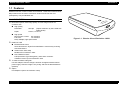
1.1 Features
EPSON Perfection 1240U consists of two models : 1240U and 1240U PHOTO.
Major features are as follows. Perfection 1240U PHOTO has the TPU
(transparency unit) as standard unit.
MAJOR FEATURES
Best suited speed / best image quality A4 color image scanner for
consumer use
High quality
Resolution:
Depth:
1200 dpi
(Optical resolution by 6 line CCD with
30600 pixels)
14 bit-in, 14 bit-out
High speed
Monochrome 2 value: 6.5 msec/line
Full Color:
7.0 msec/line
Note) 1200dpi, High speed mode
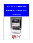
Figure 1-1. Exterior View of Perfection 1240U
EASE OF USE
EPSON Smart Panel
Same functions as ’Stylus Scan 2000/2500’. Achieve easy scanning
with three buttons.
Instant Photo Print Utility
Modified from ’Perfection 1200’
New TWAIN functions
DTR (Document Type Recognition), Auto skew correction.
TWAIN is version up from Perfection 1200.
To make it smaller and lighter
Use AC Adapter. Scanner design is slimmer and lighter without internal
power supply. Scanner weight is only 2.8kg. and Size is 269x435x93mm
(WxDxH)
Option
Film Adapter 2 (same as Perfection 1200)
Product Description
Features
8
EPSON Perfection 1240U
Revision A
1.2 Product Description
GENERAL SPECIFICATION
Product Type:
Brightness:
7 levels
Line Art:
Fixed threshold
TET (Text Enhancement Technology)
Digital halftoning:
AAS
Error Diffusion 3 modes (A, B, C)
(Bi-level, Quad-level)Dither (Resident) 4 modes (A, B, C)
Dither (User defined) 2 modes (A, B)
Flatbed color image scanner
Sub-scanning method: Movement of the Scanner-Head
Photoelectric device:
6 line alternate color CCD
Maximum Read Area:
Interface (Resident):USB (Type-B Receptacle Connector) x 1pc
8.5 x 11.7 (216 x 297mm)
USB Hosts:
All of USB ports work correctly. (The functionality of
the USB port (s) must be ensured by the vendor of the
Host)
Hub:
This device must be in the Tier 1 or 2 with
recommended USB cable. (Tier1:Host-this device
Tier2: Host-Hub-this device)
Light Source:
White Cold cathode Fluorescent Lamp
Option :
Film Adapter
Power Switch:
None
Maximum effective picture element:
10200 x 14040 pixels (1200 dpi)
Scanning Resolution:
Main
1200 dpi (Optical resolutionby 6 line CCD with 30600 pixels)
Sub
2400 dpi with Micro Step
Output resolution:
50 ∼ 4800 dpi (1 dpi step)
(9600dpi scanning is achieved by 4800dpi x200%)
Gray scale levels:
14 bits/pixel (Input 14 bits/pixel, Output 1-14/bits/
pixel)
Color Separation:
By the color filter of CCD
Zoom:
50 ∼ 200% (1% step)
Operating System: Microsoft Windows 98 (pre-install model)
Windows2000
(pre-install model, or up grade of pre-install model of
Win 98)
Millennium
(pre-install model, or up grade of pre-install model of
Win 98)
Macintosh System 8.1 or later
(Macintosh with standard connection with USB)
Scanning Speed:
Color:
7.0 msec/line
Monochrome (bi-level): 6.5 msec/line
Command level:
ESC/I (B8), FS
Gamma Correction:
CRT 2 level (A, B)
PRINTER 3 level (A, B, C)
User defined 1 level
Color Correction:
Impact-Dot Printer
Thermal Printer
Ink-Jet Printer
CRT Display
User defined 1 level
Product Description
Product Description
9
EPSON Perfection 1240U
Revision A
ELECTRICAL SPECIFICATIONS
SAFETY, EMC, EPA
Scanner unit electrical specifications
Safety:
NOM
UL 1950
CSA C22.2 NO.950
EN60950
IEC60950
EMC:
FCC Part15 Subpart B Class B
CSA C108.8 Class B
AS/NZS3548 Class B
CISPR Pub22 Class B
CNS 1348 Class B
Korea EMC
Rated input voltage:
DC24V
Power consumption:
Approx.20W (Operating)
Approx.10W (Stand-by)
Rated input current:
0.8A : DC24V
AC adapter electrical characteristics
Rated input voltage:
AC100-120V (AC100V model)
AC220-240V (AC200V model)
Input voltage:
AC 100 -120V ±10%
AC 220 - 240V ±10%
Rated input Current :
0.7A (Input AC100V)
0.4A (Input AC200V)
Rated Frequency Range:
50-60 Hz
Input Frequency Range:
49.5-60.5 Hz
Rated output voltage:
DC24V
Rated output current
0.8A
Insulation resistance:
10 MΩ at 500VDC (between AC line and
chassis)
Dielectric strength:
Product Description
CE Marking:
Low Voltage Directive 73/23/EEC
EMC Directive 89/336/EEC
EPA:
AC.1.2kV, 1 min (between AC line and
chassis)
EN60950
EN55022 Class B
EN6100-3-2
EN6100-3-3
EN50082-1
IEC60801-2/60801-3/60801-4
Energy Star Program
RESISTANCE TO ELECTRIC NOISE
Static electricity
Panel:
below 10kv, no error
below 15kv, no damage
Metal
below 7kv, no error
below 15kv, no damage
Product Description
10
EPSON Perfection 1240U
Revision A
ENVIRONMENTAL CONDITIONS
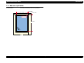
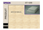
PHYSICAL DIMENSIONS AND WEIGHT
Temperature:
Dimensions:
269(W) x 435(D) x 93(H) mm
Weight:
Approx. 2.8 Kg
Operating:
5 °C to 35 °C
Storage:
-25 °C to 60 °C
Humidity:
Operating:
10 to 80%, no condensation
Storage:
10 to 85%, no condensation
RELIABILITY
MCBF:
30, 000 cycle
OPERATING CONDITIONS
Ordinary office or home conditions. Extreme dust
should be avoided.
Illumination:
Operation under direct sunlight or near strong light
source is not guaranteed and should be avoided.
435mm
Dust:
DOCUMENT
Reflective type:
Documents which has a smooth surface such as a
printing and photograph.
Transparency type (with transparency unit)
Reversal film
Negative film
93mm
269mm
Figure 1-2. Exterior Dimension of the Perfection 1240U
Product Description
Product Description
11
EPSON Perfection 1240U
Revision A
1.3 Interface Specifications
Table 1-2. Configuration
This section provides specifications of the USB, the only interface supported by
the Perfection 1240U and the Perfection 1240U PHOTO.
Element
Device
•
•
•
•
•
•
•
Class:
Vendor specific
Subclass:
Vendor specific
Protocol:
Vendor specific
Maximum packet size for endpoint 0: 64bytes
Vendor ID:
0x04B8 (Seiko EPSON Corp.)
Product ID:
0x010B
Number of possible configurations:
1
Configuration
•
•
•
•
Number of interfaces supported by this configuration: 1
Characteristics: Self-powered
Remote wake up feature: Not supported
Maximum of possible consumption: 2mA
Interface
• No Alternate setting
• Number of endpoints used by
this interface (excluding endpoint 0):
• Class:
Vendor specific
• Subclass:
Vendor specific
• Protocol:
Vendor specific
Endpoint 1
• Bulk IN transfer
• Maximum data transfer size: 64 byte
Endpoint 2
• Bulk OUT transfer
• Maximum data transfer size: 64 byte
String
Descriptor
• iManufacturer: “EPSON”
• iProduct:
“Perfection 1240U”
1.3.1 USB Specifications
Any items not included in this specification shall be in compliance with
Universal Serial Bus Specification Revision 1.1.
Configuration:
See Table 1-2.
Electric specification:
Compliant to Full Speed mode (12Mbit/s) of
Universal Serial Bus Specification Revision
1.0.
Connector:
One Receptacle (Series B)
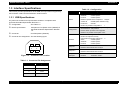
Connector Pin Assignment: See the following figure.
2
1
3
4
Figure 1-3. Connector Pin Location
Description
2
Table 1-1. Connector Pin Assignment
Product Description
Pin No.
Signal
1
VCC
2
-Data
3
+Data
4
GND
Interface Specifications
12
EPSON Perfection 1240U
Revision A
1.4 Control Codes
classification
The command levels of this scanner are ESC/I (B8) and FS. The commands
supported are shown in the table below.
Table 1-3. Control Codes
classification
Code
Set Half-tone Processing
ESC Bi
Set Auto Area Segmentation
ESC si
Down Load Dither Pattern
ESC bijd [j^2]
Set Color Correction
ESC Mi
Down Load Color Correction
ESC m d [9]
Set Threshold
ESC ti
Set Scanning Mode
ESC g i
Initialize
ESC @
Set Line Counter
ESC d i
Option Control
ESC ei
Set Film Type
ESC Ni
Set Focus Position
ESC pi
Request Focus Position
ESC q
Eject Paper
FF
Normal Response
ACK
Abnormal Response
NACK
Stop Scanning
CAN
Header
STX
Image Disposition
Name
Code
ID Request
ESC I
Status Request
ESC F
Extended Status Request
ESC f
Request Command Parameters
ESC S
Start Scanning
ESC G
Push Button Status Request
ESC !
Extended ID Request
FS I
Scanner Status Request
FS F
Scanning Parameter Request
FS S
Start New Scanning
FS G
Set Data Format
ESC D i
Set Resolution
ESC R n1 n2
Set Zooming
ESC Hi1 i2
Set Scanning Area
ESC A n1 n2 n3
Set Color
ESC C i
Set Mirroring
ESC Ki
Set Scanning Parameter
FS W
Set Brightness
ESC Li
Set Gamma Correction
ESC Z i
Down Load Gamma Table
ESC z i d [256]
Set Sharpness Control
ESC Qi
Execute Command
Set Data Format
Name
Auxiliary
Control
Image Correction
Product Description
Control Codes
13
EPSON Perfection 1240U
Revision A
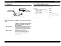
1.5 Switches
1.6 Indicator Descriptions
Push Button Switch (3) - Front (See Figure 1-4.)
LED indicator shows the various conditions by turning on/off or blinking.
Conditions indicated by LED indicator are as listed below:
Status
COPY Button
START Button
Display
Ready or receiving Push Button
Event command:
SCAN Button
Green on
Stand-by or receiving Push Button
Event command:
Green on
Busy or initialization:
Green Blinking at low speed
Error:
Red on or red blinking at high
speed or orange blinking at high
speed
Operate OFF:
Light off
Figure 1-4. Push Button Switch
EPSON Smart Panel
Same functions as 'Stylus Scan 2000/2500'. Achieve easy scanning with three
buttons.
START Button:
EPSON Smart Panel (ESP) is run, and export a
image data to application which user assigned to
relate with the START button. (This button is
user programmable)
COPY Button:
The COPY Button is assigned to the Copy utility
on ESP. The copy utility is run and activate
scanning and printing by pushing button. (This
button is not User programmable.)
SCAN Button:
The SCAN Button is assigned to the
PhotoDeluxe on ESP. Scanning starts full
automatically and export a image data to
PhotoDeluxe. (This button is not User
programmable.)
Product Description
Switches
14
EPSON Perfection 1240U
Revision A
1.7 Error Indications
FATAL ERROR
Cause:
Lamp is broken.
Power is turned on or command is received
without removing the transportation lock.
Scanner unit fault.
Disposition:
Lamp goes off and the scanner stops operating.
The bit 7 of the status byte is set.
Indicator:
Red LED High speed blinking
Remedy:
( After cause is remove )
Switch off the power and turn it on again.
Send initialization command (ESC @).
Plug out and in the USB connector.
Acceptable command:
[ESC F, ESC f, ESC @]
COMMAND ERROR
Cause:
Undefined command or undefined command
parameter is received.
Disposition:
The scanner ignores the wrong command or
parameter,( Maintain at current settings.)
Scanner sends NACK, and waits for the next
command or parameter.
Indicator:
Red LED lighting up.
Remedy:
Once the correct command is received, the error
condition is cleared.
INTERFACE ERROR
Cause:
Detects the wrong action in the communication
procedure.
Disposition:
Lamp goes off and scanner stops operating.
Indicator:
Red LED High speed blinking
Remedy:
Turn power off and then turn it on again.
Plug out and in the USB connector
Acceptable command:
None
Product Description
Error Indications
15
EPSON Perfection 1240U
Revision A
1.8 Manuscript Table
Dimension:
216 mm (Horizontal) x 297 mm (Vertical)
216 mm
3 ± 2 mm
3 ± 2 mm
Origin Point
297 mm
Front
Product Description
Manuscript Table
16
2
CHAPTER
OPERATING PRINCIPLES
EPSON Perfection 1240U
Revision A
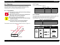
2.1 Engine Mechanism
This section explains the engine function and operating principles. Engine can
be divided into Carriage Unit and Carriage Move Mechanism.
CCD Sensor Board:
This board has Color CCD line sensor
(independent R,G,B), and controls it and drives
circuit.
Inverter Board:
This board generates voltage to drive the lamp
by pressuring up to the +24VDC and converting it
from direct current to alternating current.
Lamp:
White cold fluorescent Lamp is used as light
source. When the light quantity is not stable,
the scanner blinks the Operate light until the
light becomes stable and goes to stand-by mode.
2.1.1 Carriage Unit
Carriage unit is mainly composed of CCD sensor board, Inverter board, Lamp
(light source), Mirror and Lens mechanism.
Rear
Mirror and Lens Mechanism:The light emitted to the document
reaches the CCD sensor after being
reflected on some mirrors one after
another. Not by changing the light
source to create R/G/B light component
which can be found in the previous
models, Color CCD itself creates each
R/G/B light component.
Lamp
CCD Sensor
Board
Front
CCD Sensor
Rear
Front
Scanned image
Inverter Board
Document
Mirror2
Lamp
CCD Sensor
Board
Mirror3
B(main)
B(sub)
G(main)
G(sub)
R(main)
R(sub)
Figure 2-1. Carriage Unit Component
Mirror4
CCD Sensor
Mirror1
Lens
Figure 2-2. Mirror, Lens Mechanism
Operating Principles
Engine Mechanism
18
EPSON Perfection 1240U
Revision A
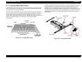
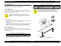
2.1.2 Carriage Move Mechanism
Scanning image is performed in the main scan direction (=1 line) by the CCD
sensor and in the sub-scan direction (=several lines) combined with carriage
unit movement. (See the figure below)
Line type, color CCD sensor can scan 1 line in main scan direction (parallel to
the carriage unit) by one time. When scanning next lines after the second line
in sub-scan direction, CR driving moves the carriage unit, which has CCD
sensor inside, and scan the other lines. The scanned data is sent to the control
board. The scanned data for “n” lines and “n-1” line are processed
consecutively.
Second
Line
Document
1 pixel
Carriage Unit slides into sub-scan direction along with the guide rail. For this
sliding operation, the carriage motor drives the timing belt attached to the
carriage unit by conveying the driving force through the drive pulley and
reduction gear. Scanning start position is determined by CR HP sensor, which
is located on the control board. Since the stepping motor is used for CR motor,
carriage home position is controlled under the open loop system. (See the
figure below)
Rear
CR HP Sensor
CR Motor
Carriage Unit
Front
First Line
Main Scan
Direction
Sub-scan Direction by
CR Movement
Timing Belt
Scanner Head
(Carriage)
Figure 2-3. Carriage Movement
Operating Principles
Driven Pulley
Drive Pulley
Transmission
Gear
Figure 2-4. Carriage Operation
Engine Mechanism
19
EPSON Perfection 1240U
Revision A
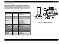
2.2 Control Circuit
The CPU (IC12) of this scanner is a one-tip 16-bit bus CPU operating at
20MHz. ASIC (IC10) manages input signal correction, image processing, and
controlling the CCD sensor board and USB interface. The power supply control
uses a DC/DC converter to generate 5 V and 12 V signals from the 24 V DC
input. Table 2-1 shows the major IC functions.
CCD Board
Image Data
(R/G/B)
8-bit
A/D
Converter Data
(IC19)
Location
IC12
CPU
24-bit Address Bus
16-bit Data Bus
MB81F6416420-102
IC13
SDRAM 4M x 16bit
IS61C6416
IC17
SRAM 64k x 16bit
IC10
USB
Controller
(IC14)
E02A34EB (IC10)
IC4,5
CR motor driver IC
M51953A
IC11
Reset IC
M27C1001-10F1
IC9
PROM 4M x 8bit
IS61C256AH
IC16
SRAM 32k x 8bit
GP1S58V
PC1
CR home position sensor
NJM2360
IC1,2
DC/DC Converter
AD9822
IC19
8bit A/D Converter
E02A35BA
IC14
USB interface control
SSR20.00BA
CR1
Clock 20MHz
NJM78M12
IC8
Regulator (12VDC)
Data Bus
Reset IC
(IC11)
PROM
( IC9)
CPU (IC12)
+24VDC
DC/DC
Converter
(IC1,2)
Regulator
(IC8)
+12VDC
SRAM
(IC16)
CLK(CR1)
+5VDC
CR
Motor
+24VDC
ASIC: Manages the following:
• Input image signal correction
• CCD control
• Line control
• Image processing
• Memory control
• Data in/output control
A3957SLBTR
Operating Principles
Lamp
&
Inverter Board
Functions
M37920
E02A32SA
USB
Address Bus
Table 2-1. Major ICs
IC
SDRAM
(IC13)
SRAM
(IC17)
CR Motor
Driver
(IC4,5)
Option
H.P.
Sensor
( PC1)
Figure 2-5. Control Circuit Diagram
Control Circuit
20
3
CHAPTER
TROUBLESHOOTING
EPSON Perfection 1240U
Revision A
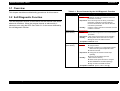
3.1 Overview
Table 3-1. Errors Detected by the Self-Diagnostic Function
This chapter describes troubleshooting procedures for this scanner.
LED Condition
Command Error
Cause:
Undefined command or undefined command
parameter is received.
Disposition: The scanner ignores the wrong command or
parameter, ( Maintain at current settings.)
Scanner sends NACK, and waits for the next
command or parameter.
Remedy:
Once the correct command is received, the error
condition is cleared.
Red LED High
speed blinking
Interface Error
Cause:
Detects the wrong action in the communication
procedure.
Disposition: Lamp goes off and scanner stops operating.
Remedy:
z Turn power off and then turn it on again.
z Plug out and in the USB connector.
Acceptable command: None
Red LED High
speed blinking
Fatal Error
Cause:
3.2 Self-Diagnostic Function
The self-diagnostic function of the scanner lets the scanner itself detect
abnormal conditions. When the scanner detects an abnormality, it
shows an error using the LED. See Table 3-1 for the errors detected by
the self-diagnostic function.
Troubleshooting
Error Type (Cause Remedy)
Red LED lighting up
Overview
z Lamp is broken.
z Power is turned on or command is received
without removing the transportation lock.
z Scanner unit fault.
Disposition: z Lamp goes off and the scanner stops
operating.
z The bit 7 of the status byte is set.
Remedy:
( After cause is remove )
z Switch off the power and turn it on again.
z Send initialization command (ESC @).
z Plug out and in the USB connector.
Acceptable command: [ESC F, ESC f, ESC @]
22
EPSON Perfection 1240U
Revision A
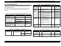
3.3 Troubleshooting
Table 3-4. The carriage unit does not operate.
This section describes how to troubleshoot problems according to
exhibited phenomenons.
See Table 3-2 that enables you to find the defective part to the unit
level. Then refer to the corresponding table for checkpoints and
solutions.
Cause
Step
Checkpoints
Finding
Remedy
CN3 on the
main board is
disconnected.
1
Check that CN3 is disconnected.
Yes
Connect CN3 on
the main board
properly.
Is grease (G-26) properly
applied?
(See Chapter 6.)
No
2
Apply grease to
the specified
points properly.
3
• With the upper housing
removed, turn the scanner on,
and check that the CR motor is
live.
• Remove the CR motor, and
check that the carriage unit
moves smoothly.
No
Check the
carriage unit,
and replace any
defective part or
disassemble and
assemble the
scanner again.
The CR motor
is defective.
4
Disconnect CN3 on the main
board. Then, using a tester,
check that the coil resistance at
each point below is 4.8Ω.
1. Between Pins 2 and 4 (Motor
side)
2. Between Pins 1 and 3 (Motor
side)
No
Replace the CR
motor.
The main
board is
defective.
5
---
---
Replace the
main board.
The carriage
drive
mechanism is
defective.
Table 3-2. Problems and Corresponding Tables to Refer to
Phenomenon
Problem
Refer to:
The scanner is turned on but
does not operate.
The scanner is not initialized.
Table 3-3
“Fatal Error” occurs. The
scanner is turned off and back
on but still shows the same
error.
The carriage unit does not
operate.
Table 3-4
The carriage unit operates but
the error is indicated.
Table 3-5
The lamp does not light up.
Table 3-6
Image is not read clearly.
Image is not read clearly.
Table 3-7
“Communication Error” occurs.
Communication with the host
is attempted again, but the
same error occurs.
USB interface error
Table 3-8
Table 3-3. The scanner is not Initialized.
Cause
Step
Connector is
disconnected.
Troubleshooting
1
Checkpoints
Check all connectors.
Are any connectors
disconnected?
Finding
Table 3-5. The carriage unit operates but the error is indicated.
Remedy
Cause
Step
Yes
Connect any
disconnected
connectors.
The scanner
upper case has
been removed.
1
Has the scanner upper
case been removed?
No
Replace the main
board.
Problem with
main circuit
board
2
---
Troubleshooting
Checkpoints
Finding
Yes
---
Remedy
Install the
scanner upper
case.
Replace the main
circuit board.
23
EPSON Perfection 1240U
Revision A
Table 3-8. USB Interface Error
Table 3-6. The lamp does not light up.
Cause
Step
Checkpoints
Finding
Remedy
CN1 on the
main board is
disconnected.
1
Check that CN1 is
disconnected.
Yes
Connect CN1 on
the main board
properly.
CN1 or CN2 on
the CCD sensor
board is
disconnected.
2
Check that CN1 or CN2 on
the CCD sensor board is
disconnected.
Yes
Connect CN1 or
CN2 on the CCD
sensor board
properly.
The connector
for the lamp is
not properly
connected to
the inverter
board.
3
Check that the connector is
properly connected to the
inverter board.
No
The lamp is
defective.
4
After replacing the lamp,
check that the lamp lights
up.
Yes
Replace the
lamp.
The inverter
board is
defective.
5
After replacing the inverter
board, check that the lamp
lights up.
Yes
Replace the
inverter board.
The main board
is defective.
6
---
---
Connect the
connector
properly.
Replace the main
board.
Table 3-7. Image is not read clearly.
Cause
Step
Checkpoints
Finding
Any mirror in the
carriage unit or
the surface of
the lamp is dirty.
1
After cleaning the mirror(s),
check that image is read
clearly.
No
Clean the
surface of the
lamp.
The CCD
sensor board is
defective.
2
---
---
Replace the
carriage unit.
The main board
is defective.
3
---
---
Replace the main
board.
Troubleshooting
Remedy
Cause
Step
Checkpoints
Finding
Remedy
The host does
not support
USB.
1
On the Windows, access
My Computer > Property >
Device Manager, and
check that Universal Serial
Bus Controller is effective.
No
Replace the host.
The TWAIN
driver attached
for the scanner
is not properly
installed.
2
Check that the driver for
the scanner is installed
properly.
No
Instal the correct
driver properly.
The USB cable
is defective.
3
After replacing the USB
cable, check that the error
is not indicated.
No
Replace the USB
cable.
The main board
is defective.
4
---
---
Replace the main
board.
Table 3-9. Option TPU does not operate
Cause
Step
Checkpoint
Finding
The cable of the
optional unit is
disconnected.
1
Is the connector
CN6 on the control
board
disconnected?
Yes
Connect the CN6
properly.
Main board is
broken.
2
---
---
Replace the main
board.
Optional unit is
broken.
3
---
Replace the
defective part of the
optional unit.
Troubleshooting
+24V line:Lamp,
Motor
+5V line: Sensor,
logic circuit.
Solution
24
4
CHAPTER
ASSEMBLY AND DISASSEMBLY
EPSON Perfection 1240U
Revision A
4.1 Overview
4.1.2 Tools
Use the tools specified in Table 4-1.
This chapter describes procedures for disassembling the EPSON
Perfection 1240U. Unless otherwise specified, the scanner can be
disassembled by reversing the disassembly procedures.
Table 4-1. Tools
Names
4.1.1 Precautions
W A R N IN G
C A U T IO N
Disconnect the power cable before disassembling or
assembling the scanner.
Wear a pair at gloves to protect your hand from the
sharp edge in the scanner mechanism.
When servicing, note the points below:
Consider the size of the scanner and make enough
room for servicing.
Since this scanner is a precision equipment,
service it on a flat, level, heavy-duty table.
Availability
Part Number
Phillips screw driver (#2)
{
B743800200
Standard screw driver
{
B743000100
Pliers
{
B740400100
Tweezers
{
B641000100
4.1.3 Screws
The screws used in the scanner are as shown in Table 4-2. Make sure
you always use the correct type and number of screws for the
assembling part. See Table 4-3 for the screw appearances.
Table 4-2. Screw Specifications
Abbreviation
CP
The directions used in this chapter are defined as shown in Figure 4-1.
In s id e
Description
Cross-recessed Pan Head screw
CBP
Cross-recessed Binding Head P-tite screw
CCP
Cross-recessed Cup Head P-tite screw
Table 4-3. Screw Appearances
R e a r (B a c k )
Head appearance
Top
Crossrecessed
R ig h t
Type
Side
Binding
L e ft
Washer
Standard
---B-tite
With Outside Toothed
lock washer
P-tite
With Spring lock
washer
Pan
F ro n t
E P S O N
Cup
Figure 4-1. Directions
Assembly and Disassembly
Overview
26
EPSON Perfection 1240U
Revision A
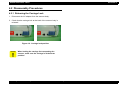
4.2 Disassembly Procedures
4.2.1 Releasing the Carriage Lock
1. Disconnect the AC adapter from the scanner body.
2. Check that the carriage lock at the back of the scanner body is
released.
Released
Locked
Figure 4-2. Carriage lock position
C A U T IO N
When locking the carriage for transporting the
scanner, make sure the carriage is at the home
position.
Assembly and Disassembly
Disassembly Procedures
27
EPSON Perfection 1240U
Revision A
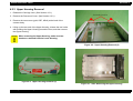
4.2.2 Document Cover Removal
1. Open the Document Cover.
2. Lift the Document Cover by its edges to remove it.
Document Cover
Figure 4-3. Document Cover Removal (1)
Assembly and Disassembly
Figure 4-4. Document Cover Removal (2)
Disassembly Procedures
28
EPSON Perfection 1240U
Revision A
4.2.3 Upper Housing Removal
1. Release the Carriage Lock. (See Section 4.2.1.)
Two Hooks on the Front
2. Remove the Document Cover. (See Section 4.2.2.)
3. Remove the two screws (gold, CBP, M3x8) at the back of the
scanner body.
4. Lifting up the rear end of the Upper Housing, release the two hooks
with pushing the Upper Housing toward the front, and then remove
the Upper Housing.
C A U T IO N
When removing the Upper Housing, make sure two
hooks are released from the Lower Housing.
Figure 4-6. Upper Housing Removal (2)
.
CBP Screws (M3x8)
Figure 4-5. Upper Housing Removal (1)
Assembly and Disassembly
Figure 4-7. After Removing the Upper Housing
Disassembly Procedures
29
EPSON Perfection 1240U
Revision A
4.2.4 Inverter Lamp / Inverter Board Removal
1. Release the Carriage Lock. (See Section 4.2.1.)
2. Remove the Document Cover. (See Section 4.2.2.)
3. Remove the Upper Housing. (See Section 4.2.3.)
4. Remove the two screws (CCP, M3x8) on the Carriage Unit. (See
Figure 4-8.)
5. Using a standard screw driver, lift up the carriage cover in the
Carriage Unit, and then move it to the back to remove it. (See Figure
4-9.)
CCP Screws (M3x8)
Figure 4-8. Carriage Unit Disassembly (1)
Figure 4-9. Carriage Unit Disassembly (2)
Assembly and Disassembly
Disassembly Procedures
30
EPSON Perfection 1240U
Revision A
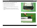
6. Disconnect the connector for the Inverter Lamp from the Inverter
Board.
Connector
7. Disconnect the 2-pin connector for the CCD sensor.
Inverter Board
8. Release the two hooks, and then remove the Inverter Board.
Connector (2-pin)
Hooks
Figure 4-10. Inverter Board Removal
Assembly and Disassembly
Disassembly Procedures
31
EPSON Perfection 1240U
Revision A
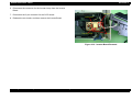
9. Remove the Lamp Cover from the Carriage Cover.
10. Remove the Inverter Lamp from the carriage cover.
C H E C K
P O IN T
• When installing the Inverter Lamp, be sure to
connect it to the hook on the Carriage Cover.
• When removing the Inverter Lamp, be careful not to
touch the Inverter Lamp directly.
• The Inverter Board will be warm immediately after
the power is turned off, so wait for it to cool
sufficiently before removing it.
Lamp Cover
Carriage Cover
Catches
Figure 4-11. Inverter Lamp Removal (1)
Lamp Cover
Inverter Lamp
Carriage Cover
Inverter Board
Figure 4-12. Inverter Lamp Removal (2)
Assembly and Disassembly
Disassembly Procedures
32
EPSON Perfection 1240U
Revision A
4.2.5 Carriage Unit Removal
1. Release the Carriage Lock. (See Section 4.2.1.)
2. Remove the Document Cover. (See Section 4.2.2.)
3. Remove the Upper Housing. (See Section 4.2.3.)
4. Remove the Clip Shaft.
5. Raise the Carriage Unit slightly to remove it from the timing belt,
remove the Carriage Guide Shaft, and then remove the Carriage
Unit.
Figure 4-14. Carriage Unit Removal (2)
Clip Shaft
Figure 4-13. Carriage Unit Removal (1)
CR Shaft
Figure 4-15. Carriage Unit Removal (3)
Assembly and Disassembly
Disassembly Procedures
33
EPSON Perfection 1240U
Revision A
6. Remove the six screws (gold, CBP, M3x8), and then remove the
Main Circuit Board Shield Plate.
6. CBS Screw (M3x8)
7. Use a standard screw driver to remove the Ferrite Core.
6. Main Board Cover
8. Disconnect the FFC Cable (white) from the Main Circuit Board.
6. CBP Screws (M3x8)
Figure 4-16. Shield Plate Removal
FFC Cable
Ferrite Core
Figure 4-17. Ferrite Core Removal
Assembly and Disassembly
Disassembly Procedures
34
EPSON Perfection 1240U
Revision A
9. FFC Cable Removal
1) Remove the two screws (CCP, M3x8) on top of the Carriage
Unit. (See Section 4.2.4.)
2) Remove the Carriage Cover. (Use a standard screw driver to
raise the Carriage Cover and then pull it backward.) (See
Section 4.2.4.)
3) Use a standard screw driver to remove the Ferrite Core.
4) Disconnect the FFC Cable (white) from underneath the
Carriage Unit (connector and hook x2).
C A U T IO N
Do not touch the mirror when removing the FFC
Cable.
Ferrite Core
Figure 4-18. FFC Cable Removal (1)
Hooks
Connector
CBS Screws (M3x4)
Figure 4-19. FFC Cable Removal (2)
Assembly and Disassembly
Disassembly Procedures
35
EPSON Perfection 1240U
Revision A
4.2.6 Carriage Motor / Timing Belt Removal
5. CBS Screw (M3x8)
1. Release the Carriage Lock. (See Section 4.2.1.)
5. Main Board Cover
6. CBS Screws (M3x8)
2. Remove the Document Cover. (See Section 4.2.2.)
3. Remove the Upper Housing. (See Section 4.2.3.)
4. Remove the Carriage Unit. (See Steps 1-8 in Section 4.2.5.)
5. Remove the six screws (gold, CBP, M3x8) and then remove the
main board cover.
6. Remove the screw (gold, CBP, M3x8) securing the CR Motor Unit.
7. Disconnect the cable for the CR Motor Unit from the connector on
the main board, and then remove the CR Motor Unit.
5. CBS Screws (M3x8)
FFC Cable
Figure 4-20. Shield Plate Removal
7. Connector
CR Motor Unit
Figure 4-21. CR Motor Unit Removal
Assembly and Disassembly
Disassembly Procedures
36
EPSON Perfection 1240U
Revision A
8. Follow the steps below to remove the Timing Belt from the CR Motor
Unit.
Transmission Gear
1) Remove the E-ring from the transmission gear.
Drive Pulley
2) Remove the transmission gear.
3) Remove the E-ring from the drive pulley.
4) Remove the drive pulley.
E-ring
Timing Belt
Figure 4-22. Timing Belt Removal
Timing Belt
Drive Pulley
Transmission Gear
E-ring
Figure 4-23. Parts in the CR Motor Unit
Assembly and Disassembly
Disassembly Procedures
37
EPSON Perfection 1240U
Revision A
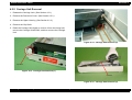
4.2.7 Main Board Removal
5. CBS Screws (M3x4)
1. Release the Carriage Lock. (See Section 4.2.1.)
2. Remove the Document Cover. (See Section 4.2.2.)
3. Remove the Upper Housing. (See Section 4.2.3.)
4. Slide the Carriage Unit slowly until you see the whole main board
cover.
5. Remove the six screws (CBP, M3x8) securing the main board
cover, and then remove the main board cover.
4. Carriage Unit
Figure 4-24. Main Board Removal (1)
Assembly and Disassembly
Disassembly Procedures
38
EPSON Perfection 1240U
Revision A
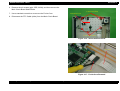
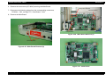
6. Remove the two screws (CP, M3x5) securing the Main Board.
Carriage FFC Connector
7. Disconnect the following cables from the corresponding connectors;
CR Motor - CN3, carriage FFC, Panel Board - CN4.
CN4 (Panel Board)
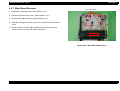
8. Remove the Main Board.
CN3 (CR Motor)
Figure 4-26. Main Board Removal (3)
CP Screw (M3x5)
Figure 4-25. Main Board Removal (2)
Figure 4-27. Main Board
Assembly and Disassembly
Disassembly Procedures
39
EPSON Perfection 1240U
Revision A
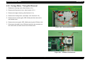
4.2.8 Panel Board Removal
1. Release the Carriage Lock. (See Section 4.2.1.)
2. Remove the Document Cover. (See Section 4.2.2.)
Hooks
3. Remove the Upper Housing. (See Section 4.2.3.)
4. Disconnect the Connector (CN1) and Hooks (x2), and then remove
the Panel Board.
C H E C K
P O IN T
In the following steps, manually move the carriage
back and forth slowly if necessary.
Connector
Panel Board
Figure 4-28. Panel Board Removal
Assembly and Disassembly
Disassembly Procedures
40
EPSON Perfection 1240U
Revision A
4.2.9 Carriage Rail Removal
CCP Screws (M3x8)
1. Release the Carriage Lock. (See Section 4.2.1.)
2. Remove the Document Cover. (See Section 4.2.2.)
3. Remove the Upper Housing. (See Section 4.2.3.)
4. Remove the Carriage Unit. (See Steps 1-6 in Section 4.2.5.)
5. Remove the two screws (CCP, M3x8) securing the Carriage Rail,
and then remove the Carriage Rail.
Carriage Rail
Figure 4-29. Carriage Rail Removal
Assembly and Disassembly
Disassembly Procedures
41
EPSON Perfection 1240U
Revision A
4.2.10 Driven Pulley Removal
Torsion Spring
Hooks
1. Release the Carriage Lock. (See Section 4.2.1.)
CCP Screws (M3x8)
2. Remove the Document Cover. (See Section 4.2.2.)
3. Remove the Upper Housing. (See Section 4.2.3.)
Driven Pulley Holder
4. Remove the Carriage Unit. (See Steps 1-8 in Section 4.2.5.)
E-ring
5. Remove the Carriage Unit. (See Steps 1-8 in Section 4.2.6.)
Driven Pulley
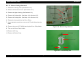
6. Release the timing belt from the Driven Pulley.
7. Use a standard screw driver to remove the Torsion Spring from the
Hook.
8. Remove the screw (CCP, M3x8) securing the Driven Pulley Holder.
Figure 4-30. Driven Pulley Removal
9. Take out the Driven Pulley Holder.
10. Remove the E-ring.
11. Remove the Driven Pulley.
Torsion Spring
Driven Pulley Holder
Driven Pulley
E-ring
Figure 4-31. Driven Pulley Unit
Assembly and Disassembly
Disassembly Procedures
42
5
CHAPTER
ADJUSTMENT
EPSON Perfection 1240U
Revision A
This scanner needs no adjustment at the level of the service, including part replacement,
specified in Chapter 4 “Disassembly and Assembly”.
Adjustment
44
6
CHAPTER
MAINTENANCE
EPSON Perfection 1240U
Revision A
6.1 Overview
Table 6-2. Lubrication Points
Figure
This chapter provides information necessary to keep the scanner function in
optimum condition constantly and to prevent troubles.
Lubrication Points
Lubrication
Figure 6-1
Transmission gear shaft of the CR motor and
drive pulley shaft.
G-26 (1x3 mm) for
each
Figure 6-1
Driven pulley shaft
G-26 (1x3 mm)
6.1.1 Cleaning
Perform cleaning when stain is noticeable. Stain on the document glass,
particularly, has a direct effect on scanned images. Therefore, be sure to clean
the glass well to remove stain thoroughly.
C A U T IO N
C A U T IO N
Excessive lubrication may cause the carriage
mechanism to be damaged or operate abnormally.
Never apply any organic solvents such as thinner or
benzene, since these may deteriorate plastic and rubber
parts.
Outer Cases
Wipe dirt off with a clean cloth, moistened with water and squeezed tightly.
To remove severe stains, use a neutral detergent.
Document Glass
Remove dust and paper debris with a dry, clean cloth. If the dirt is severe
or foreign matter is stuck on the glass, use a cloth soaked with neutral
detergent. If any trace is left, wipe it off with a dry, clean cloth again.
G-26
6.1.2 Lubrication
You need to lubricate the carriage unit if you have replaced it or notice it
making abnormal noise. See the following tables for the recommended grease
type and points to apply it.
Table 6-1. Recommended Grease
Grease Type
Contents
Part Number
Availability
G-26
40g
B702600001
E*
G-26
*: EPSON exclusive (Not on the market)
Figure 6-1. Lubrication Points
Maintenance
Overview
46
7
CHAPTER
APPENDIX
EPSON Perfection 1240U
Revision A
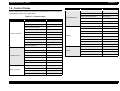
7.1 Overview
7.1.2 Connector Assignment
This section provides useful information for servicing this scanner.
Table 7-1. Connector Summary- B124MAIN
Connector
Number
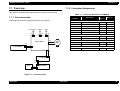
7.1.1 Interconnection
USB
CN6
CN2
2-pin
8-pin
CN5
CN3
4-pin
CN1
Panel Board
CN1
To the CCD Sensor Board
18
Table 7-2
CN2
AC Input
2
Table 7-3
CN3
To the CR Motor
4
Table 7-4
CN4
To the Panel Board
6
Table 7-5
Refer to:
CN5
To the USB Cable
4
Table 1-1
CN6
To Option
8
Table 7-6
CCD Sensor Board
4-pin
B124 MAIN
Number
of Pins
B124MAIN Board
Following figures shows interconnection of the scanner.
AC Adapter Option
Description
CN1
To the Main Board
18
Table 7-2
CN2
To the Inverter Board
2
Table 7-7
Inverter Board
CR
Motor
6-pin
CN4
CN1
To the CCD Sensor Board
2
Table 7-7
CN2
To the Lamp
2
Table 7-8
To the Main Board
6
Table 7-5
Panel Board
18-pin
CN1
CN1
CN1
CN2
CN1
Lamp
2-pin
CCD Board
Inverter Board
2-pin
CN2
Figure 7-1. Interconnection
Appendix
Overview
48
EPSON Perfection 1240U
Revision A
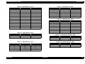
Table 7-2. Main Board - CN1
Table 7-5. Main Board - CN4
Pin No.
Signal
I/O
1, 3, 5, 7, 18
GND
-
1
GND
-
2
B
I
2
OP-LED
O
4
R
I
3
ERR-LED
O
6
G
I
4
PM-SW1
I
8
B-SH
O
5
PM-SW2
I
9
R-SH
O
6
PM-SW3
I
10
G-SH
O
11
SH
O
12
12V
O
13
F1X
O
14
F2X
O
15
RS
O
16
5V
O
17
24V
O
Pin No.
Signal
I/O
1
+24V
I
2
GND
-
Pin No.
Signal
I/O
1
+5V
O
2
GND
-
3
+24V
O
4
LOD
O
5
GND
-
6
RxD
I
7
TxD
O
8
SCK
O
Table 7-7. CCD Sensor Board - CN2
Pin No.
Signal
I/O
1
+24V
O
2
GND
-
Table 7-8. Inverter Board - CN2
Table 7-4. Main Board - CN3
Appendix
I/O
Table 7-6. Main Board - CN6
Table 7-3. Main Board - CN2
Pin No.
Signal
Pin No.
Signal
I/O
Pin No.
Signal
I/O
1
BX
O
1
LAMP
O
2
LAMP
O
2
AX
O
3
B
O
4
A
O
Overview
49
EPSON Perfection 1240U
Revision A
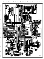
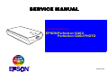
7.2 Circuit Diagram
The figure on the next page shows the circuit diagram of B124 MAIN.
B124 MAIN BOARD
Appendix
Circuit Diagram
50
EPSON Perfection 1240U
Revision A
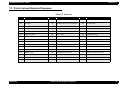
7.3 Parts List and Explode Diagrams
Table 7-9. Parts List
Ref.#
Appendix
Description
Ref.#
Description
Ref.#
Description
100
HOUSING ASSY.,LOWER;ASP
131
TIMING BELT
201
WIRE HARNESS
101
HOUSING ASSY.,UPPER;ASP
OTHERS
132
HOLDER ASSY.,PULLEY,DRIVEN
300
AC ADAPTER
102
LEVER,MOUNT,CARRIAGE
133
TORSION SPRING,238
400
POWER CABLE
103
MAT,COVER,DOCUMENT
134
SHAFT,CR
401
HARNESS
104
COVER,DOCUMENT
135
RETAINING RING
450
BOARD ASSY.,PNL
105
FERRITE CORE
136
CLIP SHAFT
500
CARRIAGE ASSY.
106
RAIL,CR
137
PULLEY,DRIVE
501
FERRITE CORE
107
FOOT
138
PULLEY,IDLE
502
HARNESS
108
DOUBLE SIDE TAPE,22X10
140
C.B.P-TITE SCREW,3X8,F/ZN
503
C.C.P-TITE,3X8,F/ZB
109
HOOK,HOUSING
141
C.C.P-TITE,3X8,F/ZB
504
COVER,CARRIAGE
110
COVER,MAIN BOARD
142
C.P.SCREW
505
LAMP SET,ASP;N
111
BASE PLATE,MAIN BOARD
150
MOTOR,ASSY.,CR
506
COVER,LAMP
112
SHEET,SLIDE
151
HOLDER ASSY.,MOTOR
507
DOUBLE SIDE TAPE,22X10
113
GASKET,ROM
152
COVER,HARNESS
508
REFLECTER,LAMP
120
LOGO PLATE 27.5X27.5
153
6N,3,F/ZN
509
SHEET,CARRIAGE,LOCK
130
PULLEY,DRIVEN
200
BOARD ASSY., MAIN
510
COVER,HOLE
Parts List and Explode Diagrams
52
EPSON Perfection 1240U
Revision A
140
140
140
120
See next page.
110
104
113
103
A
200
140
111
140
500
150
140
201
400
152
151
101
300
153
A
112
141
450
106
136
102
142
141
401
160 (For JAPAN)
134
142
130
137
135
138
135
131
140
141
109
105
140
133
108
132
109
100
107
107
GT-7700U/Perfection 1240U
Perfection 1240U PHOTO No.01
Rev.01
10244
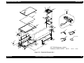
Figure 7-2. Exploded Diagram No.1
Appendix
Parts List and Explode Diagrams
53
EPSON Perfection 1240U
Revision A
506
505
508
503
510
503
504
509
501
507
502
GT-7700U/Perfection 1240U
Perfection 1240U PHOTO No.02
Rev.01
10244
Figure 7-3. Exploded Diagram No.2
Appendix
Parts List and Explode Diagrams
54
EPSON Perfection 1240U
Revision A
7.4 TPU; Parts List
Table below shows the parts list of TPU (Transparency Unit).
Table 7-10. TPU Parts List
Appendix
Number
Parts Name
800
HOUSING ASSY.,UPPER
801
B/L ASSY.
802
COVER,ILLUMINATION
803
HOUSING,LOWER
804
HOUSING,BASE
805
HOUSING,FASTEN,R
806
HOUSING,FASTEN,L
807
BOARD ASSY.,INVERTER
808
HARNESS
809
FOOT
810
SHEET,SPACER
811
C.B.B. SCREW
812
C.B.B.SCREW
813
C.B.B. SCREW
814
C.B.P-TITE SCREW,3X8,F/ZN
815
LABEL,CAUTION TPU
816
LABEL,UL;B
820
FILM HOLDER
821
FILM HOLDER;B
822
FILM HOLDER;C
823
FILM HOLDER,35
824
LABEL,FILMHOLDER
TPU; Parts List
55
EPSON Perfection 1240U
Revision A
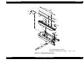
7.5 Exploded Diagram for TPU
800
808
814
B
A
807
801
B
816 FOR EAI
815
803
810
809
806
809
804
A
811
810
802
809
811
809
811
813
805
813
812
Perfection 1240U PHOTO / FILM ADAPTER
No.04
Rev.01
10244
Figure 7-4. Exploded Diagram for TPU
Appendix
Exploded Diagram for TPU
56