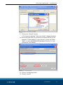
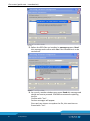
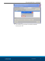
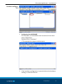
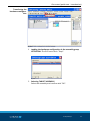
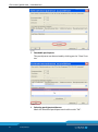
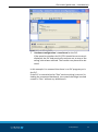
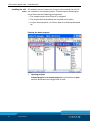
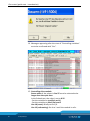
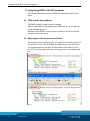
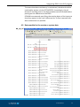
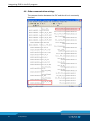
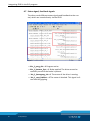
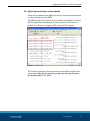
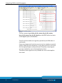
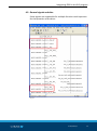
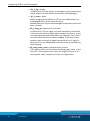
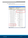
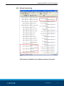
1
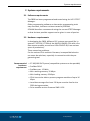
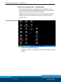
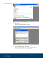
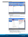
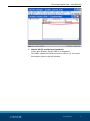
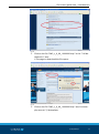
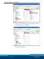
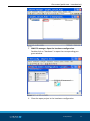
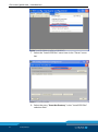
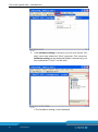
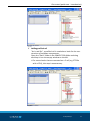
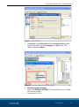
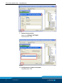
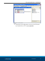
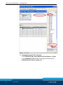
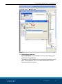
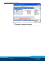
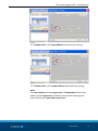
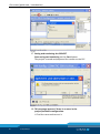
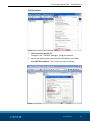
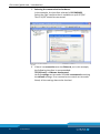
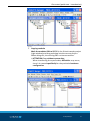
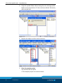
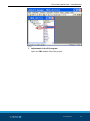
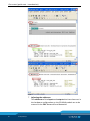
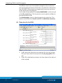
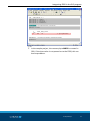
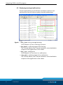
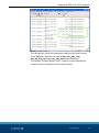
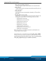
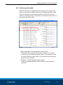
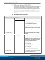
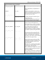
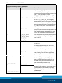
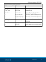
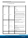
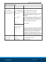
Translation of the original manual Functional module FB 20 for controlling the SCHUNK modules for the Siemens S7-300/400 PLC System Software manual Superior Clamping and Gripping Imprint Imprint Copyright: This manual remains the copyrighted property of SCHUNK GmbH & Co. KG. It is solely supplied to our customers and operators of our products and forms part of the product. This documentation may not be duplicated or made accessible to third parties, in particular competitive companies, without our prior permission. Technical changes: We reserve the right to make alterations for the purpose of technical improvement. Edition: 01.01 |06/08/2014|en © SCHUNK GmbH & Co. KG All rights reserved. Dear customer, congratulations on choosing a SCHUNK product. By choosing SCHUNK, you have opted for the highest precision, top quality and best service. You are going to increase the process reliability of your production and achieve best machining results – to the customer's complete satisfaction. SCHUNK products are inspiring. Our detailed assembly and operation manual will support you. Do you have further questions? You may contact us at any time – even after purchase. Kindest Regards Yours SCHUNK GmbH & Co. KG Spann- und Greiftechnik Bahnhofstr. 106 – 134 D-74348 Lauffen/Neckar Tel. +49-7133-103-0 Fax +49-7133-103-2399 info@de.schunk.com www.schunk.com 2 01.00|FB20 |en Table of contents Table of contents 1 About this manual .................................................................................................... 4 1.1 Applicable documents .............................................................................................. 4 2 System requirements ............................................................................................... 5 2.1 Software requirements ............................................................................................ 5 2.2 Hardware requirements ........................................................................................... 5 3 Get a start (quick start - introduction) ...................................................................... 6 4 Integrating FB20 in the PLC program ........................................................................ 48 4.1 FB20 and the data modules.................................................................................... 48 4.2 Adjusting the interface/communication ................................................................ 48 4.3 Data module for the service or system data .......................................................... 49 4.4 Time value for the FB20 ......................................................................................... 50 4.5 Displaying warnings/malfunctions ......................................................................... 52 4.6 Other communication settings ............................................................................... 54 4.7 Status signal, feed back signals .............................................................................. 56 4.8 Digital inputs/outputs at the module..................................................................... 57 4.9 General signals and data ........................................................................................ 59 4.10 Automatic referencing............................................................................................ 61 4.11 Manual referencing ................................................................................................ 63 4.12 Tap drive ................................................................................................................. 64 4.13 General specifications ............................................................................................ 65 4.14 Regulation functions............................................................................................... 66 4.15 Positioning block table ........................................................................................... 69 5 Differences between FB10 / FB20 ............................................................................ 70 5.1 FB switching: input + in/output .............................................................................. 70 5.2 FB switching: output ............................................................................................... 74 6 FB CMD commands ................................................................................................. 76 7 Notes on versions .................................................................................................... 78 01.00|FB20|en 3 About this manual 1 About this manual This manual describes the FB20 functional module. It serves as a drive module to control the Profibus. 1.1 Applicable documents • The FB20 has been developed for the S7-300/400 PLC system of Siemens AG. Therefore, the documentation of the CPU should be observed, including the manuals for the STEP7 programming software. • The Profibus installation guidelines which were created by the PNO Profibus user organization must be followed. • The functions of the drive modules, some of which are triggered by the FB20, are described in the manual "Schunk Motion Tool, Software Guide". 4 01.00|FB20|en System requirements 2 System requirements 2.1 Software requirements The FB20 has been programmed and tested using the V5.5 STEP 7 Manager. Older programming software or alternative programming tools may also work, but have not been tested by SCHUNK. SCHUNK therefore recommends using the current STEP7 Manager so that the best possible support can be given in case of queries. 2.2 Hardware requirements In developing the FB20, different PLC systems were used (for instance S7-315 2DP, ET200s of the IM151-8 PN/DP CPU with a Profibus master module, as well as a VIPA CPU315-SB, from various years of production). These caused no problems. For the various CPUs and their firmware, incompatible behavior can never be ruled out, especially in connection with the programming tool. Recommended hardware requirement • S7-300/400 PLC System (compatible systems are also possible) • Profibus DPV0 • Profibus max. 1.5 Mbit • Min. working memory 32 kByte • Min. loading memory 32 kByte • CPUs have to be able to process program modules of up to 16 kByte • Local data storage of at least 512 bytes must be free for the FB20 during execution. • Drive module version firmware SMP V1.56 01.00|FB20|en 5 Get a start (quick start - introduction) 3 Get a start (quick start - introduction) In this chapter, a project is created by way of example, such as how a drive module can be designed so that in the end, the drive module can be controlled via the variable table. SCHUNK recommends that technicians (particularly those who are inexperienced) carefully read this chapter and work through it point by point. Creating a PLC project Fig. 1 1 OPENING the SIMATIC Manager In order to create a new project, the Simatic Manager must be started. 6 01.00|FB20|en Get a start (quick start - introduction) Fig. 2 2 FILE > NEW At first, a new project must be created. Fig. 3 3 Define the project NAME and PATH Each project must have a name. This should be unique and have a storage location that is specified here. 01.00|FB20|en 7 Get a start (quick start - introduction) Fig. 4 4 View project The project name is displayed on the left. To get a better overview, we recommend setting the view to details. Fig. 5 5 Adding a PLC station: ADD > STATIONS Mark the project and select the 300/400 Simatic series. This is the foundation of the hardware configuration. 8 01.00|FB20|en Get a start (quick start - introduction) Fig. 6 6 Simatic 300 (1) is added as a foundation In the right window, Simatic 300 (1) is displayed. To further expand the folder structure, click on (+) in front of the project name in the left window. 01.00|FB20|en 9 Get a start (quick start - introduction) Installing GSD In order to be able to proceed with the creation of the project, the files GSD files from the Schunk company must be installed. The installation of the GSD files is described on the following pages. If the GSD files have already been installed, the next 17 steps can be skipped. Reference source of the GSD file • On the supplied data carrier • Download at www.schunk.com Fig. 7 1 Download from the internet http://www.schunk.com Open the "Service Downloads" areas. 10 01.00|FB20|en Get a start (quick start - introduction) Fig. 8 2 Click on the file "SMP_v_X_XX_ XXXXXXXX.zip" in the "2.4 Mechatronics" area. The page to download the file opens: Fig. 9 3 Click on the file "SMP_v_X_XX_ XXXXXXXX.zip" and, for example, save at C:\ Sammelbox. 01.00|FB20|en 11 Get a start (quick start - introduction) Fig. 10 4 Open the C:\Sammelbox directory and unpack the zip file in the folder SMP_v_X_XX_ XXXXXXXX. Fig. 11 The zip file is unpacked. 12 01.00|FB20|en Get a start (quick start - introduction) Fig. 12 5 SIMATIC manager: Open the hardware configuration. Double-click on "Hardware" to open the corresponding program window. Fig. 13 6 Close the open project in the hardware configuration. 01.00|FB20|en 13 Get a start (quick start - introduction) Fig. 14 7 Select the "Install GSD files" menu item in the "Extras" menu bar. Fig. 15 8 Select the entry "from the directory" in the "Install GSD files" selection field. 14 01.00|FB20|en Get a start (quick start - introduction) Fig. 16 9 Click on the "Search" button. The selection window "Search for Folder" dialog box opens. 10 Select the path with the previously unzipped GSD file (in our example, C:\Sammelbox). In this directory, select the folder "SMP_v_X_XX_ XXXXXXXX\GSD\Hardware Version 5.x" and click on the "OK" button. Fig. 17 11 Click on "All displayed files". 12 Click on "Install". 01.00|FB20|en 15 Get a start (quick start - introduction) Fig. 18 13 Before the GSD files are installed, a message appears. Read this message and confirm with Yes if the installation is to be carried out. Fig. 19 14 As a result, another window may open. Read this message and decide on how to proceed. SCHUNK recommends replacing the file. Confirm with "Yes". Further messages will appear. Since we have chosen to replace the file, this must be confirmed with "Yes". 16 01.00|FB20|en Get a start (quick start - introduction) Fig. 20 15 The installation has now been successfully completed. Continue with "OK". 01.00|FB20|en 17 Get a start (quick start - introduction) Fig. 21 16 Click on the "Close" button to complete the installation. Fig. 22 17 Close the hardware configuration, then open it again so that the data is transferred. 18 01.00|FB20|en Get a start (quick start - introduction) Hardware configuration Fig. 23 1 Configuring the HARDWARE For the project, the assemblies must be entered in the hardware configuration. Double click on "Hardware" The appropriate program window opens. Fig. 24 2 If the hardware configuration is opened without the hardware catalog, it could look like this. 01.00|FB20|en 19 Get a start (quick start - introduction) Fig. 25 3 If the hardware catalog is not open, you can click on the "Catalog" menu item under the "View" menu bar. This is how the hardware catalog can be displayed/hidden. Alternatively, the key combination "Ctrl+K" can be used. Fig. 26 The hardware catalog is now displayed. 20 01.00|FB20|en Get a start (quick start - introduction) Fig. 27 4 Adding profiled rail "As in real life", a profiled rail is needed as a basis for the construction of hardware components. Open the "Rack" folder in the SIMATIC 300 folder and drag and drop it into the empty window on the left. For control units that are mounted on a C rail (e.g. ET200s with a CPU), this step is unnecessary. Fig. 28 01.00|FB20|en 21 Get a start (quick start - introduction) 5 Adding a POWER SUPPLY UNIT Optionally, a power supply can be dragged and dropped from the PS300 folder to the first position of the profiled rail. Fig. 29 6 Selecting and configuring CPU Drag and drop the CPU to the second position of the profiled rail. It is imperative to pay attention to the order number of the S7 Simatic when selecting the CPU . ATTENTION: For this sample project, the PROFIBUS interface should be set to address 2. 22 01.00|FB20|en Get a start (quick start - introduction) Fig. 30 7 At General, the profile path and the storage location are displayed, but they cannot be changed changed there. Click "New" and add a subnet. Fig. 31 8 Checking network settings Retain the DEFAULT SETTINGS. This should be set to 1.5 Mbit, with the DP profile. Continue with "OK". 01.00|FB20|en 23 Get a start (quick start - introduction) Fig. 32 9 Subnet characteristics Retain the DEFAULT SETTINGS. Continue with "OK". Fig. 33 10 Configuration of subnet concluded Continue with "OK". 24 01.00|FB20|en Get a start (quick start - introduction) Fig. 34 11 Alternatively, the configuration can be set via the DP master bus. Double-click on "DP" to open properties. 01.00|FB20|en 25 Get a start (quick start - introduction) Fig. 35 12 Adding the Schunk PTA v5.3a drive In the PROFIBUS DB, select Additional Field Devices > Drives in the Schunk PTA v5.3a folder and drag and drop them to PROFIBUS(1) DP master system (1). 26 01.00|FB20|en Get a start (quick start - introduction) Fig. 36 13 Adjusting the addresses Set the ADDRESS of the PROFIBUS interface according to the manufacturer's guidelines. The address of the module can be specified accordingly via the MTS "Schunk Motion Tool". For more information, see the appropriate documentation. 01.00|FB20|en 27 Get a start (quick start - introduction) Fig. 37 14 Setting the I/O addresses of the module Double-click on the address to configure the start addresses for the input and output area. 28 01.00|FB20|en Get a start (quick start - introduction) Fig. 38 15 Double-click on the input address and make the setting. Fig. 39 16 Double-click on the output address and make the setting. NOTE The start address of the output area is independent of the start address of the input area. SCHUNK recommends selecting the same area for the input and output area. 01.00|FB20|en 29 Get a start (quick start - introduction) Fig. 40 17 Saving and translating the PROJECT Start saving and translating via the Start button. The project is saved and prepared for transfer to the PLC. Fig. 41 18 This message appears if there is an error in the project/hardware configuration. Find the cause and correct it. 30 01.00|FB20|en Get a start (quick start - introduction) PG/PC interface Fig. 42 1 PLC connection on the PC Change to the "SIMTAIC Manager" program window. 2 Select the appropriate communication hardware via the Extras PG/CPU interface. This is to be set up accordingly. Fig. 43 01.00|FB20|en 31 Get a start (quick start - introduction) 3 Selecting the communication hardware In the example, the interface selected is PLCSIM(MPI). Select the right interface that is available on your PC/PLC. The CPU/PLC should be connected. Fig. 44 4 If there is a connection over the Ethernet, as in this example, the following interface is recommended: TCP/IP(Auto) -> VMware Accelerated Various settings can be made. SCHUNK recommends retaining the default settings. If no connection to control can be established, all the settings have to be checked. 32 01.00|FB20|en Get a start (quick start - introduction) Transferring the hardware configuration Fig. 45 1 Loading the hardware configuration in the assembly group ATTENTION: The PLC has to be in "Stop". Fig. 46 2 Selecting TARGET ASSEMBLY Select the assembly and confirm with "OK". 01.00|FB20|en 33 Get a start (quick start - introduction) Fig. 47 3 Reachable participants The participants are determined by clicking on the "View" button. Fig. 48 4 Selecting participant addresses Mark the identified participant and confirm with "OK". 34 01.00|FB20|en Get a start (quick start - introduction) Fig. 49 5 Hardware configuration is transferred to the PLC. If the question whether the PLC/CPU should be set to stop is displayed, the PLC had previously not been set to stop or the wrong control was selected. The transfer may have to be aborted. In this example it is assumed that there is no PLC program yet in the PLC. If the PLC is now switched to "Run" and everything is correct (including the connected hardware), the system should go into and remain in "Run" without any disturbance. 01.00|FB20|en 35 Get a start (quick start - introduction) Installing the soft- All modules that are important to control the module via the PLC ware are included in the sample project. The description following below is based on the following prerequisites: • The sample project from Schunk is unzipped. • The project described above was created and it works. • In the created projects, no further data is included and backed up. Copying the basic program Fig. 50 1 Opening projects Created projects and sample projects from Schunk are open and the windows are arranged side by side. 36 01.00|FB20|en Get a start (quick start - introduction) Fig. 51 2 Copying modules Mark the modules OB1 to SFC15 in the Schunk sample project (right window) and drag and drop into the current project. When doing this, the existing OB1 can be overwritten. ATTENTION:Copy without system data. When transferring the system data, difficulties may occur, since it is created specifically for the particular hardware configuration Fig. 52 01.00|FB20|en 37 Get a start (quick start - introduction) 3 Copy the symbol folder. When doing this, the existing symbol folder can be overwritten if it has not been edited. Otherwise, data may be lost! Fig. 53 4 Replace the object and the entire contents. Fig. 54 5 Close the sample project The modules were copied. The sample project can now be closed. 38 01.00|FB20|en Get a start (quick start - introduction) Fig. 55 6 Adjustments in the PLC program Open the FB1 module from the project. 01.00|FB20|en 39 Get a start (quick start - introduction) Fig. 56 7 Adjusting the addresses The addresses of the inputs and outputs that have been set in the hardware configuration on the SCHUNK module are to be entered in the FB1 Network2 and Network4. 40 01.00|FB20|en Get a start (quick start - introduction) Fig. 57 8 The KOP/AWL/FUP editor can be closed. Fig. 58 9 Loading components into the CPU ATTENTION: Set the CPU to a STOP state to prevent interference and uncontrolled movements. In order to do this, the RUN/STOP switch can, for example, be set to STOP on the CPU. The modules OB1 to DB121 are to be marked. By clicking the icon in the Symbol menu bar, the program is transferred.gestellt werden. 01.00|FB20|en 41 Get a start (quick start - introduction) Fig. 59 10 CAUTION: If modules to be copied should be available on the CPU, they will be overwritten when the message is confirmed and cannot be recovered. Die The CPU should not contain any program (precondition to running): Before this message is confirmed, you should be absolutely sure that you are connected to the correct PLC and that you really want to overwrite the modules. Once you have ensured that no damage will occur by moving the assemblies, the PLC can be set to "Run". If everything was done correctly, the system should start up without any disturbance and remain in the run mode. Otherwise, the errors must be eliminated. 42 01.00|FB20|en Get a start (quick start - introduction) Fig. 60 11 Open the variable table by double-clicking on it The FB20 module can be manually controlled via the table of variables. For this, it is important to make sure beforehand that no damage can be caused by transferring the module. 01.00|FB20|en 43 Get a start (quick start - introduction) Fig. 61 12 Observe variables Go online with the table of variables; activate it with the Glasses symbol. 44 01.00|FB20|en Get a start (quick start - introduction) Fig. 62 13 Controlling variables Scrolling down to the end of the page is controlled via the symbol. It is important to scroll down so that all values are accepted. For this, it may become necessary that the control function needs to be executed several times or that already controlled specifications/signals/data are deleted. 01.00|FB20|en 45 Get a start (quick start - introduction) Fig. 63 14 Messages appearing after the start of "Controlling variables" are to be confirmed with "Yes". Fig. 64 15 Controlling drive module Status value of the values in line 37 must be selected to be longer than the cycle time. In the Schunk test, the value is set to 0.25 . - Set the variables to true(Ctrl and 1) - Set the variables to false (Ctrl and 0 Line 10 (reset): Briefly set to 1/0. Line 12 (referencing): Set it to 1 until the module is refe- 46 01.00|FB20|en Get a start (quick start - introduction) renced. See lines 48 and 49 if both are on "True". The drive can turned to the left or right by setting the variables to the status value to true in the line 15/16. The speed can be increased/decreased by changing the value of the variable in line 26. The "force" can be increased/decreased by changing the value of the variable in line 29 These are just a few examples. This table of variables is used to test/try the module’s functions. Always be sure that no harm or injury can result. 01.00|FB20|en 47 Integrating FB20 in the PLC program 4 Integrating FB20 in the PLC program This chapter describes how the FB20 can be used in the PLC program. 4.1 FB20 and the data modules The FB20 requires a data instance module. Here, a single DB can be assigned per FB20 call-up, as can be seen in the example project. Because of the FB20’s multi-instance capability, data can also be created in the static area. 4.2 Adjusting the interface/communication The communication between the PLC and the drive takes place via the I/O data. Since with the FB20, the addresses of the data from the communications are specified by pointer, the data can be in the I/O area, the peripheral area, the flag area or in the data module. Fig. 65 48 01.00|FB20|en Integrating FB20 in the PLC program To ensure that data consistency is maintained, the data should be read and/or written via the SFC14/SFC15. Accordingly, the addresses in the flag area or the data module must be cached before passing on the addresses to the FB20. SCHUNK recommends specifying the starting bytes of the inputs so that they appear in the cross-reference list, so that improved software maintenance is possible. 4.3 Data module for the service or system data db_sys_sd Fig. 66 01.00|FB20|en 49 Integrating FB20 in the PLC program The DB20 is used as an intermediate storage for the communication signals and parameters of the drive, as well as for information from the FB20. These signals are important for service, but can also be used by the user program. For the data to be updated, the value L#50331648 is to be entered at the dii_sf_cod input. This causes the current signals and data to be entered into the DB. The disadvantage is that it is detrimental to the cycle time. This option should therefore only be used if it is absolutely necessary. 4.4 Time value for the FB20 Fig. 67 1 In FB, some time functions are required. For this, the current PLC cycle time must be turned on at the dii_ztw_zyklus FB input. 2 If the FB is called up by an alarm, the time value of the alarm is to be entered. 50 01.00|FB20|en Integrating FB20 in the PLC program Fig. 68 3 In the sample project, the memory byte MB20 is created in OB1. If the time value is not passed on to the FB20, this can lead to problems. 01.00|FB20|en 51 Integrating FB20 in the PLC program 4.5 Displaying warnings/malfunctions Various signals/data are provided for the display of alarms and malfunctions that will help to rapidly eliminate malfunctions. Fig. 69 Signals • bio_1_bm = event message/warning. If the output is 1/True, a warning is present. • byo_bmnr = coded message of the warning. The "Schunk Motion Tool" manual contains a more detailed description of the significance of the values. • bio_1_sm = malfunction. If the output is 1/True, there is a malfunction. • byo_smnr = coded message of the malfunction. The "Schunk Motion Tool" manual contains a more detailed description of the significance of the values. 52 01.00|FB20|en Integrating FB20 in the PLC program Fig. 70 The FB regularly sends the command cmd (hex.96) which causes more diagnostic data on the outputs byo_sm_info_cmd, byo_sm_info_mnr, reo_sm_info_data to be displayed. The manual "Schunk Motion Tool" contains a more detailed description of the command and its output values. 01.00|FB20|en 53 Integrating FB20 in the PLC program 4.6 Other communication settings The communication between the PLC and the drive is constantly checked. Fig. 71 54 01.00|FB20|en Integrating FB20 in the PLC program • bio_1_kom_io = communication status The communication is OK if a 1/True signal is present. If this is not the case, the hardware configuration must be checked. – Settings of the E/A addresses, – Settings at the SFC14/15 and at the address pointers with cycle time. – Furthermore, the Profibus and the electrical system of the drive must be checked. • rei_sm_zt_max_kom = communication check time The maximum permissible communication time should be entered in it. If the time has been set too small or too large, many malfunctions may occur or a communication/malfunction may be detected too late. A time value of 0.3 seconds would be a good value. 01.00|FB20|en 55 Integrating FB20 in the PLC program 4.7 Status signal, feed back signals The drive sends different status signals and feedback to the control, which are issued directly via the FB20. Fig. 72 • bio_1_prog_akt = 1 Program active • bio_1_bremse_fest = 1 Brake applied. The drive cannot be manually turned if the brake is present. • bio_1_bewegung_vhr = 1 The motor of the drive is moving • bio_1_mot_blokiert = 1 The motor is blocked. This signal is often used for gripping. 56 01.00|FB20|en Integrating FB20 in the PLC program 4.8 Digital inputs/outputs at the module Some drive modules have digital I/O on the electronic board which can be controlled via the FB20. The FB20 prepares the signals of the module accordingly, so that a 0/False signal corresponding to 0 volt is present at the input or output, or if there is a voltage of 24 V at the 1/True signal. Fig. 73 The outputs located on the board can be controlled via these four input signals (bii_do_01_anst, bii_do_02_anst, bii_do_03_anst, bii_do_04_anst) on the FB20. 01.00|FB20|en 57 Integrating FB20 in the PLC program Fig. 74 The four output signals (bio_di_01_status, bio_di_02_status, bio_di_03_status, bio_di_04_status) on the FB20 show the status of the digital inputs on the board. The I/Os of the module are regularly queried by the FB20 after X commands. Since more important functions are sent to the module or queried, and/or called up more frequently, it may take more PLC cycle time for the inputs/outputs to be processed. Therefore, these signals are only suitable for non-critical application times. Therefore, these signals are only suitable for non-critical application times. 58 01.00|FB20|en Integrating FB20 in the PLC program 4.9 General signals and data Some signals are responsible for multiple functions and important for the operation of the drive. Fig. 75 01.00|FB20|en 59 Integrating FB20 in the PLC program • bii_1_frg = Enable In the case of a 0/False signal, an emergency stop is performed, which results in a malfunction and must be acknowledged. • bii_1_reset = Reset When changing from 0/False to 1/True, the malfunction is acknowledged/reset, which stops the drive. Malfunctions can only be acknowledged if they have previously been resolved. • bii_1_bwg_pf = Movement via P flank In the case of a 1/True signal, only one movement is executed in the case of a positive edge (signal change from 0 to 1), at the corresponding movement functions (e.g. tapping). This is to ensure that after the drive has been stopped, it can only be activated as soon as a positive edge (change from 0 to 1 signal) is detected. Thus, an independent start-up can be prevented (e.g. when tapping. • bii_mot_strom_nenn = Nominal motor current The engine current can be limited via the rei_sw_i value. In the case of a 1/True signal at the input, the engine is set to its nominal power value, irrespective of the set target value. 60 01.00|FB20|en Integrating FB20 in the PLC program 4.10 Automatic referencing Before positioning can be executed, the axis must be referenced. Fig. 76 01.00|FB20|en 61 Integrating FB20 in the PLC program • bii_1_ref_auto_asf = Automatic referencing If a signal 1/True is present, referencing is started, even if the axis is referenced. If the signal 0/FALSE appears while referencing, the axis goes into stop and referencing must be carried out again. • bio_1_ref_io_fu = Drive referencing status If the axis runs in the referencing are executed, the output will be 1/True. • bio_1_ref_io_fb = FB referencing status After the drive has been referenced (bio_1_ref_io_fb=1), a movement may still be made after internal setting of the drive (e.g. by moving X millimeters towards to the reference point). Only when the drive stands still after X time (set by rei_ref_auto_io_ev) for X time, a 1/True signal is output. 62 01.00|FB20|en Integrating FB20 in the PLC program 4.11 Manual referencing Fig. 77 This function is disabled in the software and has no function. 01.00|FB20|en 63 Integrating FB20 in the PLC program 4.12 Tap drive Fig. 78 • bii_1_tip_neg and bii_1_tip_pos There is the opportunity to touch the drive, even if the drive is not referenced. Once the drive is released accordingly, the drive can be moved. • rei_sw_v_tip Speed setting for the touch function. 64 01.00|FB20|en Integrating FB20 in the PLC program 4.13 General specifications Fig. 79 • rei_sw_vr Setting the ramp for acceleration/deceleration. • rei_sw_i Specification of the maximum current. The current should not be set to a value of less than 0.001. • rei_sw_ruck Setpoint setting for the "Jerk". For details see, the manual. • rei_sw_zt_pos The setpoint time for positioning when used in accordance with the control mode. The drive calculates its own speed to reach the position in the time allowed. The setpoints described above are regularly transmitted to the drive. For details see, the manual. 01.00|FB20|en 65 Integrating FB20 in the PLC program 4.14 Regulation functions Before a control function is performed, any changed values are transferred to the drive before the control functions are started. For the start of the control functions, there are three possibilities. The prerequisite is that the drive is operational (referenced and with no malfunction). Fig. 80 66 01.00|FB20|en Integrating FB20 in the PLC program • bii_1_mot_fkt_asf If the current is on 1/True here, the control function is executed using the current settings. If a value is changed, such as the control functions or a position specification, the control function is automatically started. With a signal change from 1/True to 0/False, the drive is stopped. • bii_1_mot_fkt_start The positive edge (signal change from 0/False to 1/True) launches the control. With a signal change from 1/True to 0/False, the drive is stopped. • bii_1_mot_fkt_start_pf This signal represents the same function as the I_CMD_START_POS input signal from the FB10. This means that the control function is started with the signal change from 0/False on 1/True and is only stopped again when the function has been executed/completed, or due to factors such as malfunctions, stop signals or signal release. • io_fkt_vfs_nr, reo_fkt_sw_i, reo_fkt_sw_pos If the control functions could be completed, the outputs give out the values that were set at the start of the control function. Fig. 81 01.00|FB20|en 67 Integrating FB20 in the PLC program • bio_1_fkt_io and bio_1_fkt_nio These two signals output status before the control function. • bio_1_fkt_io If the control function has been executed successfully, the current is on 1/True. • bio_1_fkt_nio If the function was not executed or aborted, a 1/True will be given out. • by_fkt_mod = Control mode Specification of the appropriate cmd command number for executing the control mode. The following values are valid: – CMD (Hex.b0): move pos – CMD (Hex.b1): move pos time – CMD (Hex.b3): move cure – CMD (Hex.b5): move vel – CMD (Hex.b7): move grip – CMD (Hex.b8): move pos rel – CMD (Hex.b9): move pos time rel – CMD (Hex.c1): exe phrase More information on the CMD commands can be found in the "Schunk Motion Tool" manual. A special function is started with the value by_fkt_mod = #16#ff. This special function makes it possible to control the drive via the speed setting and the value of the current. Here, the requirements of rei_sw_v_reg and rei_sw_i are updated repeatedly. 68 01.00|FB20|en Integrating FB20 in the PLC program 4.15 Positioning block table With the MTS tool, a positioning block table can be stored in the drive. It is possible to add functions to this positioning block table which are contrary to the functionalities of the FB20 in their execution. Therefore, there is the option to control the drive only via the positioning block table. Fig. 82 • bii_1_vfs_prio = Positioning block table priority If there is a 1/True signal at this input, the drive can only be controlled via the positioning block table. The emergency stop and stop functions remain active. The malfunction acknowledgement is also disabled. • ii_vfs_nr = Positioning block table number Here, the positioning block table number to be executed is specified. 01.00|FB20|en 69 Differences between FB10 / FB20 5 Differences between FB10 / FB20 In this chapter, the wiring of the FB10, the predecessor module for controlling the drive modules, is compared to the current FB20. The result is an overview of the similarities of the FBs as well as a presentation of the latest developments on the FB20. With this information, the change from the FB10 to the FB20 can be made quickly. 5.1 FB switching: input + in/output FB10/20 switching: input + in/output FB10 FB20 Remark I_ADDR pi_fu_adr_in The specification of the module address is now done via a pointer. This has the following advantages: pi_fu_adr_out - The I/O addresses can differ. - Entry in the cross-reference list. - Higher flexibility, because the entire address range of the CPU can be used. --- db_sys_sd This DB contains additional signals/data that can be used for the user and the service. I_FL_CYCLE_BYTE --- The flashing indicators are no longer needed. --- bii_1_bwg_pf This signal specifies whether or not a motion can be started only by a positive edge signal after the drive has been stopped (e.g., due to a malfunction or a stop function). This signal has an influence on the following signals: - bii_1_tip_neg - bii_1_tip_pos - bii_1_mot_fkt_asf - bii_1_vfs_prio I_ACK bii_1_reset Acknowledgment of a malfunction or reset of internal FB signals/data. I_RESEND_CMD --- It is no longer used to prevent an independent/unexpected start. 70 01.00|FB20|en Differences between FB10 / FB20 FB10/20 switching: input + in/output FB10 FB20 Remark I_CONT_POS_FEEDB --- The position information, as well as other signals/data, are updated at intervals. I_ENABLE bii_1_frg Release of the motion. If there is a 0 signal, an emergency stop is executed until it has been acknowledged or the drive has come to a stop. I_CMD_REF_MODUL bii_1_ref_auto_asf An extension of referencing modes was provided. Automatic referencing corresponding to the (I_CMD_REF_MODUL), as well as manual referencing as a reserve signal. bii_1_ref_hand_asf I_CMD_JOG_PLUS bii_1_tip_neg The functionalities have been improved. There are the options of switching directly, as well as changing the setpoint velocity during execution. I_CMD_JOG_MINUS bii_1_tip_pos The functionalities have been improved. There are the options of switching directly, as well as changing the setpoint velocity during execution. I_CMD_STOP_MOTION bii_1_mot_stop The functionality has been improved. Once the stop signal reached the FB (even if it was only on during one PLC cycle), the stop function is executed until there is no further motion and the brake holds the engine firmly. I_CMD_START_POS Start the motor function / control. Two types of the function starts the CMD commands have been included to suit their differing needs in the PLC programming needs. With the "bii_1_mot_fkt_start" signal, the function is started when there is a positive edge, while with the "bii_1_mot_fkt_asf" signal, the control function is always executed as soon as new values appear. This is useful in automatic, or sequencer mode, because only the new values need to be changed without the neces- bii_1_mot_fkt_asf bii_1_mot_fkt_start 01.00|FB20|en 71 Differences between FB10 / FB20 FB10/20 switching: input + in/output FB10 FB20 Remark sity of creating a signal change over several PLC cycles. Here, the control function is executed only as long as the "bii_1_mot_fkt_start" or the "bii_1_mot_fkt_asf" signals are 1/True. bii_1_mot_fkt_start_pf This signal has the same functionalities as the "bii_1_mot_fkt_start" signal, with the only difference that it does not have to remain present. This is to simulate the same/a similar functionality as "I_CMD_START_POS" with the old FB. bii_1_mot_strom_nenn This signal has been added so that a simple switch to the nominal current of the module can be done, which is useful for the touch feature, for instance. --- bii_do_01_anst bii_do_02_anst bii_do_03_anst The outputs of the drive are controlled at intervals according to the signal status in the FB. bii_do_04_anst I_POS_MODE by_fkt_mod Specification of the regulation functions of xB0..C1. As a new special function, the command xff has been added to control the drive only by the target value V/I. --- bii_1_vfs_prio The execution of the positioning block has priority. Only the stop and emergency stop functions are still functional. I_POS_SEQUENCE ii_vfs_nr Positioning block number specification Positioning blocks with ACK, referencing or similar functions cannot be executed if they are in contradiction to the functionality of the FB20. I_POS_VELOCITY rei_sw_v_tip rei_sw_v_reg I_POS_ACCELERATION 72 01.00|FB20|en rei_sw_vr For the manual or automatic operating modes in the systems, two speed specifications were now made in the new FB, which simplify the work of an PLC programmer. Accelerating value Differences between FB10 / FB20 FB10/20 switching: input + in/output FB10 FB20 Remark I_POS_CURRENT rei_sw_i Specified current I_POS_POSITION rei_sw_pos Specified position I_POS_JERK rei_sw_ruck Accelerating jerk I_POS_TIME rei_sw_zt_pos Time for positioning (regarding the "MovPosTime" command) --- rei_ref_hand_swv Referencing: speed set value (reserve) --- rei_ref_hand_zt_pos Referencing: time positioning (reserve) --- rei_ref_hand_rel_pos Referencing: relative position (reserve) I_RES_TIME --- Not used due to the structure of the FB I_TIMER_WDOG rei_sm_zt_max_kom Maximum time for communication monitoring. --- dit_ztw_zyklus PLC cycle time for time functions --- dii_sf_cod Service signals for analyzing functionality 01.00|FB20|en 73 Differences between FB10 / FB20 5.2 FB switching: output FB10/20 switching: output FB10 FB20 Remark M_WARNING bio_1_bm Signal status warning is output by the drive module. M_ALARM bio_1_sm Status signal malfunction is output by the drive module. --- byo_bmnr Warning information which was indicated on the CMD x89 return value. If the status signal Warning is not present; the value is reset after some time (max. communication). M_ERROR byo_smnr Malfunction information that was given on the x88 CMD return value. If the status signal Warning is not present; the value is reset after some time (max. communication). --- byo_sm_info_cmd This message, detailed information is read at intervals, via the CMD x96 --- byo_sm_info_mnr --- reo_sm_info_data The command and the data issued via the three output values. --- bio_1_kom_io Status signal from the FB that the communication with the drive is activated. M_REFERENCED bio_1_ref_io Status signal from the drive module that is referenced. --- bio_1_ref_io_fb Delayed status signal from the FB that the referencing has been completed, after which there is no longer any movement. --- 74 01.00|FB20|en bio_1_ref_frg_bwg Status signal for the manual referencing (reserve) bio_1_ref_frg_bwg In manual referencing, the signal is set to 1 to indicate that the drive can be moved now. Differences between FB10 / FB20 FB10/20 switching: output FB10 FB20 Remark M_PROG_ACTIVE bio_1_prog_akt Status signal from drive module. M_BRAKE_ACTIVE bio_1_bremse_fest Status signal from drive module. M_IN_MOTION bio_1_bewegung_vhr Status signal from drive module. M_MOTION_BLOCKED bio_1_mot_blockiert Status signal from drive module. M_POS_REACHED --- bio_1_fkt_io If the positioning block has priority, the signal which is output via "bio_1_fkt_io" is passed on. bio_1_fkt_nio In normal execution of the functions, CMD B0 .. C1, a distinction is made between execution OK/NOK. NOK is set if the function is aborted during its execution. bio_di_01_status Status signal from the digital input of the drive module. bio_di_02_status bio_di_03_status bio_di_04_status –- io_fkt_vfs_nr reo_fkt_sw_i reo_fkt_sw_pos If the control function has been successfully completed, the values which were present at the start of the control start function on the FB are also given out. This gives the programmer the additional option to evaluate the values in the program, e.g. for the progression conditions for the sequences. M_ACT_VELO reo_iw_v Current speed M_ACT_CURR reo_iw_i Current electrical current M_ACT_POS reo_iw_pos Current position 01.00|FB20|en 75 FB CMD commands 6 FB CMD commands CMD commands used in the FB CMD Remark x80 Some basic data representing the limits of the target values are read Read out configura- to be used in the FB. tion x8B Acknowledge malfunction x90 Not stop x91 Stop x92 Referencing x95 get state x96 get detailed error info x97 They are prepared and initially disabled until the problems on the Manual referencing drive side have been eliminated. xA0 Processed by interval. Setting speed xA1 Processed by interval. Setting acceleration value xA2 Processed by interval. Setting jerk value xA3 Processed by interval. Setting the current value xA4 Processed by interval. Set the time value 76 01.00|FB20|en FB CMD commands CMD commands used in the FB CMD Remark xB0 move pos xB1 move pos time xB3 move cure xB5 Speed movement xB7 move grip xB8 move pos rel xB9 Move pos time rel xC1 exe phrase xE1 DI/DO reading/writing Not all functions can be used by this positioning block table (e.g. referencing). Alternatively, the priority of the positioning block table (bii_1_vfs_prio) is to be activated. Read/Write is executed cyclically, along with many other commands. This leads to the up-dating time being slow. 01.00|FB20|en 77 Notes on versions 7 Notes on versions Version Date Remark Recommendation The communication or data exchange should be carried out via the SFC14/15. Alternatively, the address of the module can also be placed in the I / O area. V02-00.08.00 04.03.2014 Behavior In the Profibus protocol, the value '-1.175495e-038' appeared . Cause It could be that the programm activated a wrong address. Es wird vermutet, das ein Sprung an die verkehrte Stelle gemacht wurde. Remedy Jump mark set, and in part 't074:' the jump instruction adapted. V02-00.07.00 25.10.2014 Behavior 1 The data of get detial info were not consistent. 2 The referencing is not always executed. Cause 1 Variable interchanged. 2 If the current values are retrieved during referencing, this can lead to problems at the drive side. Remedy 1 Variable of the return from the module was used accordingly. 2 The corresponding queries were blocked: – 0xA0 - SET TARGET VEL [Velocity] – 0xA1 - SET TARGET ACC [Acceleration] – 0xA2 - SET TARGET JERK [Jerk] – 0xA3 - SET TARGET CUR [Current] – 0xA4 - SET TARGET TIME [Time] – 0x96 - GET_DETAILED_ERROR_INFO The following commands shall not be used. They could cause problems: – 0xA6 - SET TARGET POS [Posi1on] – 0xA7 - SET TARGET POS REL [rel.Positon] 78 01.00|FB20|en Notes on versions Version Date Remark V02-00.06.00 26.09.2013 Behavior Sporadically, the control values are not used for positioning or not controlled accordingly. Cause If the default values change during transmission to the fu, the current value is cached, but it is not the right one. Remedy All control relevant data are cached while sending the order (cmd.: a0..4), to use this value as a reference value. V02-00.05.00 24.09.2013 Behavior Sometimes the drive moves only at a slow speed to the position that was set by the previous speed. Cause The FB20 differs tip-v or control-target-v, but the module works only with one speed value. It could be that there is no target-v transmitted during the control drive. Therefore, the module drove with the last target-v. Remedy If the speed movement is performed (cmd.: b5), the target-v cache will be reset. V02-00.04.00 04.02.2013 Behavior The status signal "blocked" does not appear. Cause With the FB20, the values for the control (e.g. current, position, etc.) are regularly resent. If the drive is being controlled, the status bit is reset by this and will be reevaluated. This can often no longer be re-activated. Remedy If the drive is now being controlled, only a control value is resent if it has changed. V02-00.03.00 14.12.2012 Behavior If the control values, the control mode and, in the same PLC cycle, the start signal has come in, the function was not performed. Only after a repeated start impulse. Remedy When changing the control mode (for example, cmd.#b08 --> cmd.#b0), the signal "#sd.fkt_mod_delta" is set to 1, so that the start pulse is suppressed. Now the signal is only triggered if neither a start nor a control function is active. 01.00|FB20|en 79 Notes on versions Version Date Remark V02-00.02.00 27.11.2012 Behavior If the module/drive has already been referenced, no repeated referencing could be performed. Remedy If the internal referencing bit exists, no new referencing can be controlled. For that reason, the internal referencing bit is now reset by means of the positive edge to start the referencing. V02-00.01.00 21.11.2012 Behavior The drive is started via cmd XB8, travels to position but does not report that the function was concluded with io and remains being controlled by the FB. Remedy The "fu fpr position io" control signal is not reset if the same position is to be approached again. Although the brake is opened, the io signal position remains. Therefore it was necessary to intermediately save the signal which is set/reset by the flanks. Here, some problems occurred. The control for setting the signal for the io function has been improved. Addressing via pointer was extended so that db-addresses can be specified now, too. 80 01.00|FB20|en