1
I Sears, I
owner s
manual
MODEL NO.
C944.526460
CRAFTSMAN
CAUTION:
Read RULES for
Safe OPERATION
and INSTRUCTIONS
Carefully
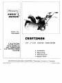
22", 7 H.P. SNOW THROWER
• Assembly
• Operating
• Maintenance
• Repair Parts
IMPORTANT
RULES FOR SAFE OPERATION
TRAINING
1. Read the operating and service instruction manual
carefully. Be thoroughly familiar with the controls
and the proper use of the equipment. Know how to
stop the unit and disengage the controls quickly.
2. Never allow children to operate the equipment.
Never allow adults to operate the equipment without proper instruction.
3. Keep the area of operation clear of all persons,
particularly small children and pets.
4. Exercise caution to avoid slipping or falling, especially when operating in reverse.
PREPARATION
1. Thoroughly inspect the area where the equipment
is to be used and remove all doormats, sleds, boards,
wires, and other foreign objects.
2. Disengage all clutches and shift into neutral before
starting the engine.
3. Do not operate the equipment without wearing
adequate winter outer garments. Wear footwear
which will improve footing on slippery surfaces. Do
not wear long scarfs or loose fitting clothing which
may become entangled in machinery.
4. Handle fuel with care; it is highly flammable.
(a) Use an approved fuel container.
(b) Never add fuel to a running engine or hot engine.
(c) Fill fuel tank outdoors with extreme care. Never
fill fuel tank indoors.
(d) Replace gasoline cap securely and wipe up
spilled fuel.
5. Use a grounded three-wire plug-in for all units
equipped with electric starting motors.
6. Adjust the impeller housing height to clear gravel
or crushed rock surface.
7. Never attempt to make any adjustments while the
engine is running (except where specifically recommended by manufacturer).
8. Let engine and machine adjust to outdoor temperatures before starting to clear snow.
5. Stop the engine whenever you leave the operating
position, before unclogging the impeller housing
or discharge guide, and when making any repairs,
adjustments, or inspections.
6. Take all possible precautions when leaving the
unit: shift into neutral, disengage the drive (primary) clutch, shut off the engine, and remove the
key.
7. When cleaning, repairing, or inspecting, make
certain the impeller and all moving parts have
stopped. Disconnect the spark plug wire, and keep
the wire away from the plug to prevent accidental
starti ng. Disconnect the cord on electric starter
motor.
8. Do not run the engine indoors, except when starting the engine and for transporting
the snow
thrower in or out of the building. Open the outside
doors; exhaust fumes are dangerous.
9. Do not clear snow across the face of slopes.
Exercise extreme caution when changing direction
on slopes. Do not attempt to clear steep slopes.
10. Never operate the snow thrower without proper
guards, plates, or other safety protective devices
in place.
11. Never operate the snow thrower near glass enclosures, automobiles, window wells, drop ofts, etc.
without proper adjustment of the snow discharge
angle. Keep children and pets away.
12. Do not overload the machine capacity by attempting to clear snow at too fast a rate.
13. Never operate the machine at high transport
speeds on slippery surfaces. Use care when
backing.
14. Never direct discharge at bystanders or allow
anyone in front of the unit.
15. Disengage power to the impeller when snow
thrower is transported or not in use.
16. Use only attachments and accessories approved
by the manufacturer of snow thrower (such as
electric starter kits, cabs, etc.).
17. Never operate the snow thrower without g.ood visibility or light. Always be sure of your footing, and
keep a firm hold on the handles. Walk; never run.
OPERATION
1. Do not put hands or feet near or under rotating
parts. Keep clear of the discharge opening at all
times.
2. Exercise extreme caution when operating on or
crossing gravel drives, walks, or roads. Stay alert
for hidden hazards or traffic. Do not carry passengers.
3. After striking a foreign Object, stop the engine,
remove the wire from the spark plug, thoroughly
inspect the snow thrower for any damage, and .repair the damage before restarting and operating
the snow thrower.
4. If t:le unit should 'start to vibrate abnormally, stop
the engine and check immediately for the cause.
Vibration is generally a warning of trouble.
MAINTENANCE
AND STORAGE
1. Check shear bolts, engine mounting bolts, etc. at
frequent intervals for proper tightnes~ .to be sure
the equipment is in safe working conditIOn.
2. Never store the machine with fuel in the fuel tank
inside a building where open flame or spar~s a:e
present. Allow the engine to cool before storing In
any enclosure.
3. Always refer to owner's manual in.structions for
important details if the snow thrower IS to be stored
for an extended period.
4. Run the machine a few minutes after throwing snow
to prevent freeze up of the impeller.
craftsman
quality snow removal equipment
For one year from purchase date, Simpsons-Sears will replace, Free of Charge,
any part or parts including the engine, found, upon examination to be defective
under normal use and service, by reason of defects in material and workmanship. The warranty is void if the unit has been the subject of misuse.
A modern low cost maintenance agreement is available on this product,
extend the guarantee. Contact your nearest Simpsons-Sears Store.
Compliance with radio interference
with resistor spark plug only.
regulations
certified,
to
replace spark plug
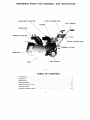
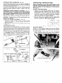
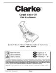
LEFT HANDLE
J
DEFLECTOR
IMPEllER
ClUT\
~
~.
SKID
PRIMARY
CLUTCH
/
GUARANTEE
3
ASSEMBLY
5
OPERATING
7
MAINTENANCE
12
SERVICE CHECK LIST
13
REPAIR PARTS
14
ENGINE REPAIR PARTS
18
For shipping
purposes, the handles and operating
controls of your snow thrower have not been assembled
to the unit. The carton of parts, in which this owner's
manual was found, contains all components and hardware necessary to complete the assembly.
NOTE: The terms Left Hand (L.H.) and Right Hand
(R.H). refer to your left and right hands when you
stand in the operator's position behind the unit.
ATTENTION:
FOR EASIER ASSEMBLY, TILT SNOW
THROWER FORWARD SO THAT IT RESTS ON SAFETY
BAR AS SHOWN (FIG. 2).
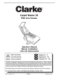
FIG. 4
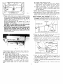
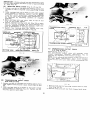
SHIFT CONTROL ROD ASSEMBLY
(Fig. 5 to 8)
1. Assemble one 3fs -16 flange nut (A) to end
control rod having the longest threaded
Flange of nut must face toward threaded
shift control rod as shown (Fig. 5 and 6).
the nut the full length of the threads.
TRANSMISSION
CONTROL
of shift
portion.
end of
Thread
BRACKET
(C)
'Z' SLOT
HANDLE
PLATE
LOCATING
PIN
SHIFT
CONTROL
ROD
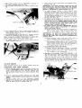
HANDLE ASSEMBLY
1. Slide lower two holes of R.H. handle over weld
screws on R.H. side of snow thrower chassis (Fig.
3). Assemble formed washer to upper weld screw,
and secure handle with two 3fs -16 flange nuts.
Tighten finger tight only.
2. Assemble L.H. handle to snow thrower in same
manner.
~
CHASSIS
r'0 ~I
~~~~f*
WELD SCREWS
A
TRANSMISSION
CONTROL BKT.
/
TRANSMISSION
~.....
~~
HANDLE
c'
WASHER
/
FIG. 6
rn~
\ "'"· -J
\
ROD________
/
FORMED
!
CONTROL
SHIFT~~.
RIGHT
~.:y
SHIFT
@ FLANGE
NUTS
3. Assemble handle plate to handles (Fig. 4), using
four 5/16-18 x 1 ¥.i carriage bolts and four 5/16-18
flange nuts. Tighten securely.
4. Tighten four 3fs -16 flange nuts securely against
lower end of both handles (Fig. 3).
~~\
~
~
\\.
2. Position other end of shift control rod up through
slot in top of handle plate, so that locating pin on
rod engages the "Z" slot in handle plate (Fig. 5).
Swing transmission
control bracket upwards (Fig.
6), and insert lower end of shift control rod into
hole in transmission control bracket (Fig. 5 and 6).
3. Assemble one 3fs -16 flange nut (B), with flange up,
to lower end of shift control rod (Fig. 6). Do not
tighten nut.
4. IMPORTANT: Position transmission
shift lever in
neutral position (Fig. 7), approximately in the centre
of slot in rear cover. Rotate wheels of unit; wheels
should turn freely if neutral has been obtained. Shift
lever may have to be moved up or down slightly
from centre of slot in order to obtain neutral.
TRANSMISSION
BOLTS
(4)
;J2~==liQ;:;
~;'~;E::~
Bi~IFT
":ER
L
TRANSMISSION
CONTROL
BRACKET
SElF TAPPING
SCREWS
5. Place shift control rod in neutral position (centre
of "l" slot at handle plate) (Fig. 8). Holding shift
control rod in this position, thread lower 3fB -16 flange
nut (B) (Fig. 6) up to transmission control bracket.
Tighten upper flange nut (A) down onto top of
transmission control bracket.
Be sure locating pin is not cocked in "l" slot of
handle plate (Fig. 8). Pin should be perpendicular
to face of handle plate.
CAUTION:
Do not tighten nut and bolt securing
transmission
control bracket to transmission
shift
lever (Fig. 6). These parts must pivot freely.
6. IMPORTANT: Be sure transmission stays in neutral
when shift rod locating pin is moved through entire
neutral range at handle plate as shown in Fig. 8.
Wheels of unit should turn freely through entire
neutral range. If they do not, make one of the following adjustments:
(a) Loosen lower flange nut (B).
(b) Tighten
upper flange nut (A) down against
transmission
control bracket one or two turns.
This will, in effect, lengthen the shift control
rod.
(c) Tighten lower flange nut up against transmission control bracket, and check again that
transmission
remains in neutral through entire
neutral position.
7. Attach spring to locating pin on shift control rod,
and to hole in bottom of handle plate (Fig. 8).
8. Assemble one 3/B -16 jam nut (C) (Fig. 5) all the way
onto threads at top of shift control rod. Screw
control knob onto shift control rod until tight, and
tighten jam nut (C) securely against knob.
CHUTE CONTROL ROD ASSEMBLY
(Fig. 9 and 10)
1. Slide lower adjusting bracket onto chute control
rod. NOTE: adjusting bracket must be angled toward
the sprocket on chute control rod as shown (Fig. 9).
EYE BOLT
1
ADJUSTING BKT.
1
~
/
.
~~~
\ /
~
I
/1
rn
I
ffi
CHUTE CONTROL ROD
~
L.H.HANDLE
FIG. 9
2. Slide eye bolt onto chute control rod, and slide
rubber bushing onto shank of eye bolt.
3. Assemble eye bolt to outside of L.H. handle, and
secure with one 1/4 -20 lock nut (0). Do not tighten
nut.
4. Assemble lower adjusting bracket to lower support
bracket using two 5/16-18 x % carriage bolts (E)
and two 5/16-18 flange nuts (F) (Fig. 10).
SPROCKE~Y
If transmission
stays in "Forward" drive inside the
neutral range, adjust flange nuts at lower end of
shift rod (Fig. 5 and 6):
(a) Loosen upper flange nut (A).
(b) Tighten lower flange nut (B) up against transmission control bracket one or two turns. This
will, in effect, shorten the shift control rod.
(c) Tighten upper flange nut down onto transmission control bracket, and check again that transmission
remains
in neutral
through
entire
neutral range.
If transmission
stays in reverse within the neutral
range, adjust flange nuts on lower shift control
rod:
,)1\
SUPPORT BKT.
". ~
FIG. 10
5. Raise the lower adjusting bracket into position SO
that sprocket on chute control rod engages holes
in flange at base of chute assembly, and tighten
two 5/16-18 flange nuts (F).
6. Tighten 1/4 -20 locknut (D) on eye bolt (Fig. 9), being
careful to position eye bolt perpendicular to chute
control rod.
7. Assemble rubber grip to end of chute control rod
(Fig. 9).
CHECKING
CHUTE OPERATION
(Fig. 10)
If sprocket teeth tend to jam in holes in flange at
base of chute assembly, lower the sprocket slightly by
loosening the two 5/16-18 flange nuts (F) and lowering
the lower adjusting bracket.
If sprocket teeth skip across holes in flange, raise the
sprocket by loosening two nuts (F) and raising the
lower adjusting
bracket slightly.
Tighten
nuts (F)
securely.
INTERLOCK WIRING HARNESS ASSEMBLY (Fig. 11)
IMPORTANT: For the protection of yourself and others,
your snow thrower is equipped with a safety interlock
system which allows operation of the unit only from
the operator's position. To complete the assembly of
the interlock
system, connect safety wire on R.H.
handle to wire at base of engine as shown (Fig. 11).
CAUTION: If these wires are left disconnected,
unit will not operate.
THROTTLE
CONTROL ASSEMBLY
your
Before attempting
to use your snow
carefully all the operating instructions
sure you understand the function of all
again the "Rules for Safe Operation"
this manual.
BEFORE STARTING ENGINE
1. Remove oil filler plug and dipstick on L.H. side of
engine and check oil level. Fill to "FULL" mark on
dipstick with S.A.E. 5W-30 oil (Fig. 13). Pour slowly
to prevent air lock. To check oil level correctly,
screw filler plug and dipstick all the way in. Overfilling the engine may affect performance. Tighten
filler plug secur:ely to prevent leakage.
2. Fill fuel tank with any regular grade of fresh, clean
gasoline. Lead free gasoline may be substituted.
Do not use Ethyl or High Octane gasoline.
(Fig. 12)
J _rT
~.'\ll'lill
1. As~emble throttle control to back of handle plate
uSing two # 10-16 x 112 self-tap screws (0) as shown'
tighten securely.
'
2. Press plastic knob firmly onto throttle control lever
(Fig. 12).
---------:::l1
/'
, ;
/_
_____
.....
o
2-SPEED SHIFT LEVER
The 2-SPEED SH IFT LEVER (Fig. 7) provides 2 speed
ranges which are selected with lever at rear of chassis.
The high speed (H I) is to be used for norma I snow removal and low speed (LO) is desirable for use when
extremely heavy work is required. Move lever to the
left for "H I" and to the right for "LO". Select "H I" or
"LO" speed prior to shifting control rod to "FORWARD"
or "REVERSE" drive. It may be necessary to move
snow thrower forward or backward slightly to align
cogs in transmission
so that shift lever can be completely engaged in "HI" or "LO" position.
thrower, read
below and be
controls. Read
at the front of
FIG. 13
Oll
Flll'
;Y'
_
....R PlU .. "
-"l
O.IPST ..'.~'.
.'=:i2J;Y' '.
•
.
'~/?
~"'.//-
/
TO START ENGINE
NOTE: All small gasoline engines tend to be difficult
to start in cold weather. Since this unit will always
be used in cold weather, we recommend you store it
in a heated area.
1. Place primary clutch lever up into disengaged
("OUT") position and place impeller clutch shift rod
in disengaged ("OUT") position (Fig. 14 and 15).
2. Move shift control rod to "NEUTRAL" position in
"Z" slot of handle plate (Fig. 16).
3. Move throttle control down to "FAST'" position (Fig.
16).
4. Turn choke lever to "FULL" choke position (Fig. 17).
Turn ignition switch located on engine shroud to
"ON" position (Fig. 17).
5. IF TEMPERATURE IS BELOW loaF: Depress primer
button on carburetor (Fig. 17), 2 or 3 times.
Step #5 may be omitted if temperature is above loaF.
6. Pull engine over rapidly with starter rope.
7. As engine warms up, slowly return choke
"OFF" position (Fig. 17).
lever to
4. Move primary clutch lever down into engaged ("IN")
position (Fig. 14).
IMPORTANT: The safety interlock system on
will automatically
stop the engine when the
clutch is engaged unless the safety lever on
handle is maintained in closed position (Fig.
this unit
primary
the R.H.
16).
5. To obtain forward motion of snow thrower move
2-speed shift lever into "La" position (Fig. 7). With
left hand, move shift control rod down into "Forward" position - bottom of "Z" slot in handle plate.
To stop forward motion: Move shift control rod back
up into "Neutral" position - centre of "Z" slot in
handle plate (Fig. 16).
6. To obtain reverse motion: With left hand, move shift
control rod up into "Reverse" position and hold in
that position (Fig. 16). NOTE: Return spring (Fig. 8)
behind handle plate will automatically
return shift
rod to "neutral"
position when shift control rod is
released from "reverse" position.
7. To obtain impeller operation: IMPORTANT: Be sure
front of unit is clear of bystanders or obstacles
before operating impeller.
(a) Before leaving operating position to engage impeller clutch lever, move primary clutch lever
up into disengaged ("OUT") position (Fig. 14).
IMPORTANT: The engine will always stop if the operator attempts to leave the operating position and
releases the safety lever without first disengaging the
primary clutch.
(b) Move impeller clutch shift rod on R.H. side of
unit to engaged ("IN") position (Fig. 15).
(c) Return to operating position (behind handles),
and squeeze safety lever on R.H. handle. Now
move primary clutch lever down slowly into engaged ("IN") position (Fig. 14). The impeller is
now operating and ready to throw snow.
8. TO DISENGAGE IMPELLER DRIVE:
(a) Before leaving operating
position, disengage
primary clutch lever ("OUT" position) (Fig. 14).
(b) Move impeller shift rod to "OUT" position (Fig.
15). Impeller is now disengaged.
9. Operaticn of discharge chute and deflector:
(Fig.
18). The direction of snow discharge from the chute
can be varied 180°, from left to right. To discharge
snow to your left, turn chute control rod handle
clockwise. Rotate handle anti-clockwise
to obtain
snow discharge to your right. The distance the snow
will be thrown can be adjusted by tilting the deflector up or down (Fig. 18).
TO STOP ENGINE
Move throttle
control
up to "STOP"
position
(Fig. 16).
OPERATING YOUR SNOW THROWER
1. Before starting engine, be sure primary clutch lever
is up in disengaged ("OUT") position (Fig. 14), impeller clutch shift rod is in ("OUT") position (Fig.
15), and shift control rod is in neutral position (Fig.
16).
2. Assume
engine.
speed.
3. Squeeze
against
hold on
operating position behind unit, and start
Using throttle control, adjust to moderate
safety lever up into operating
position
R.H. handle with right hand, and maintain
lever and R.H. handle. (Fig. 16).
CAUTION: Always stop engine before changing deflector position. Keep hands away from chute and
deflector when impeller is operating.
All V-Belts stretch a certain amount during normal
use. Consequently,
the snow thrower drive belt will
probably require adjustment after the first five hours
of operation. Belt adjustment is required whenever the
primary clutch lever drops below the warning line on
the back plate.
If your unit stays in "Forward" Drive position when
shift control rod is moved into neutral range, adjust
flange nuts at lower end of shift rod: (Fig. 5 to 8).
(a) Loosen upper flange nut.
(b) Tighten lower flange nut up toward transmission
control bracket one or two turns. This will, in
effect, shorten the shift control rod.
(c) Tighten upper flange nut down onto transmission
control bracket.
If your unit stays in "Reverse" drive when shift control
rod is returned to neutral range, adjust flange nuts on
lower shift control rod:
.
(a) Loosen lower flange nut.
(b) Tighten upper flange nut down onto transmission
control bracket one or two turns. This will, in
effect, lengthen the shift control rod.
(c) Tighten lower flange nut up against transmission
control bracket.
NOTE: Failure to adjust drive
result in excessive belt wear.
GROUND CLEARANCE ADJUSTMENT
The type and depth of snow will also influence
snow can be thrown.
distance
10. OPERATING ADJUSTMENTS
CAUTION: Always stop engine and disconnect spark
plug wire before cleaning, lubricating or adjusting
your snow thrower.
DRIVE BELT
TO TIGHTEN
belt as required
will
DRIVE BELT
1. Remove four self-tap screws (G) and one locknut
(H), and remove belt cover (Fig. 19).
(Fig. 20)
Slots in skids provide adjustment up or down. To increase or decrease ground clearance of impeller housing prop up front of unit using a piece of wood or
similar object and loosen two Ys -16 nuts on each skid.
Raise or lower the skids to desired height.
In icy or packed snow conditions, runners on skids
FIG. 19
2. Loosen four bolts (J) securing back plate to engine
(Fig. 19).
3. Loosen four engine mounting bolts at base of engine,
(Fig. 14).
4. Engage primary clutch lever ("IN" position), and
move engine toward rear of unit until primary clutch
lever rests approximately in the centre of slot (above
warning line).
5. Tighten engine bolt securely, making sure rear base
line of engine is in alignment with rear of chassis.
6. Check alignment of five holes in belt cover with four
holes in back plate (G), and bolt (H). Slide back
plate backwards or forwards until hole alignment
is obtained. Tighten four bolts (J) securing back
plate to engine.
7. Replace belt cover using four self-tap screws at
(G) and locknut at (H). Tighten securely.
SHIFT CONTROL ROD ADJUSTMENT
The "NEUTRAL"
position of the snow thrower transmission has a wide range and, in some cases, the
transmission
may remain in "Forward" or "Reverse"
position when the shift control rod is moved into the
"Neutral"
range at the handle plate. This may not
become apparent until used in heavy snow. If this
situation occurs, stop engine and proceed with the
following adjustments:
FIG. 20
may force the unit to ride on top of snow, preventing
effective snow removal. When this occurs, remove
skids and invert them so that knife edges of skids
will cut through snow.
CHAIN ADJUSTMENTS
(Fig. 21)
Correct chain tension is of vital importance in obtaining efficient performance. To obtain chain tension as
illustrated in Fig. 21, each chain should be adjusted
by following the steps below:
3/8'PLAY~
--
-
IMPORTANT: Chains should not be excessively tight.
Correct chain tension will allow a total of approximately
3/B
play (Fig. 21).
II
(A)
IMPELLER DRIVE CHAIN (Fig. 21, 22 and 23)
1. Loosen nut (N) on carriage bolt holding nylon idler
in place in slot in impeller chain guard (Fig. 22 and
23).
2. Slide carriage bolt up or down in slot until correct
chain tension is obtained. Tighten nut (N). NOTE:
If correct chain adjustment cannot be obtained
using the nylon idler further chain adjustment can
be obtained
by adjusting
position of impeller
bearings:
3. Move carriage bolt and nylon idler to top of slot
(Fig. 23) and finger tighten.
4. Loosen impeller bearing bolts (K) (Fig. 23) on each
side of impeller housing, and move bearings and
impeller assembly forward to increase chain tension, or backwards to decrease tension.
5. Tighten four bearing bolts (K), making sure that
distances (L) and (M) are equal in Fig. 22.
IMPELLER
B~A~~NG---CARRIAG-E-BOLT
I.CLUTCH
COVER
,-BEARING
I NYLON
. IDLER
TRANSMISSION
OUTPUT CHAIN
L.H.
BOTTOM VIEW
FIG. 25
TRANSMISSION OUTPUT CHAIN
(L.H. Side of Unit)
Refer to Fig. 25, 26 and 27.
The transmission output chain will probably never
require adjustment.
However, adjustment
may be
obtained by adjusting transmission position:
(C)
NOTE: Since adjusting the position of the transmission
will also affect transmission
input chain tension,
loosen nut (O) and nylon idler before proceeding (Fig.
25).
--.,
---~-r.-
TRANSMISSION
C~Q~----r!
Q
I
BOLTS (4)
c.#'/
/1
cf~,---A/dJ
_~GINE
BO~YS-.i~) - =-=
~.l./ .
S;/EVE~ /"'''VEO \:
j
~SPEED
\
(B)
TRANSMISSION
INPUT
(R.H. Side of Unit)
\)
\:
FIG. 23
- TRANSMISSION
CONTROL
BRACKET
SElF TAPPING
SCREWS
\
/
V
"-
CHAIN
1. Loosen nut (0) on carriage bolt holding nylon chain
idler against transmission input chain (Fig. 24 and
25).
2. Slide carriage bolt up or down in slot until correct
chain tension is obtained (Fig. 21). Tighten nut (0)
securely against nylon idler.
FIG. 26
1. Remove bolt and nut securing control lever to shift
lever (Fig. 26, 27).
2. Remove knob and jam nut from 2-speed shift lever.
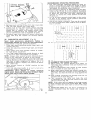
RECOMMENDED
OPERATING PROCEDURES
1. The most efficient
operating speed for snow removal is dependent on depth and weight of snow.
Experience will establish the most efficient operating speeds for particular snow conditions.
2. Recommended patterns of throwing snow are illustrated in Fig. 29 and 30. In the situation illustrated
in Fig. 29, the discharge chute should be positioned
to throw the snow with the wind, requiring the
operator to reverse the chute position at the end
of each run.
3. In Fig. 30, snow removal should begin in the centre
of area to be cleared. Chute position should be
reversed at end of each run.
4. Use of tire chains is optional. They may be removed
for snow removal from hard surfaces such as blacktop or concrete.
FIG. 27
3. Remove seven self-tap screws from rear cover plate
(Fig. 26), and remove rear cover plate.
4. Loosen nuts on four bolts inside chassis securing
transmission
to chassis, and slide transmission
toward rear of chassis until proper output chain
tension is obtained (Fig. 21). Tighten four nuts to
secure transmission
and re-assemble all parts.
5. Re-adjust input chain (section B above) using nylon
chain idler (Fig. 25). Tighten nut securely against
idler.
II
\
t+
lllll
jH I I
1]00 ~------)
, C--~---------.....-~ .........-----......---.-C
I
--~-----)
-+--
(D)
CARBURETOR
ADJUSTMENT
(Fig. 28)
Never make unnecessary
adjustments.
Factory recommended settings are correct for most applications.
If adjustment is required, proceed as follows:
1. Close high speed adjusting needle finger tight, and
re-open one turn.
2. Close idle adjusting needle finger tight, and re-open
one turn.
3. Start engine and move throttle control to "FAST"
for high speed adjustment.
4. Turn high speed adjusting needle forward or back
I/S
turn at a time until engine runs moothly.
NOTE: Always allow several seconds between adjustments for the carburetor to adjust to new setting.
5. With engine running smoothly, turn high speed ad-.
justing needle out (counter-clockwise)
I/S
turn. This
may add a slight roughness to engine, but it is
advisable to obtain a slightly rich mixture for operation under load.
6. Move throttle control to "SLOW" position for idle
adjustment.
7. Turn idle adjusting needle in or out I/S turn at a
time until engine idles smoothly.
IMPORTANT:
Never attempt
to change
maximum
engine speed. Bypassing the governor to obtain higher
speeds may cause severe engine damage.
I.L'A~
~.~"r:;=-r
-:::.
-
~L~
~
At;'i€;,:~
\-\
\
J FIG
28'
...-
-+----
...--
----+- ---+- ------..-..
------+- -----..
----..)
~
-+--
...--
......---
~
-+----
....--
III Holl
111
lH
II
n~n
1
flAlf
1
j
1
j
1
FIG. 30
JMn
j
U IU 1
TO ASSEMBLE TIRE CHAINS TO TIRES:
(a) Place chains on ground behind each wheel, so
that ends with connector links are furthest from
wheels (Fig. 31).
(b) Pull unit backwards onto chains so that wheels
rest in middle of each chain (Fig. 31).
(c) Wrap chain around wheel and connect inside link.
Make sure there are no kinks in the cross links or
side links, and that the links are snug against the
tire.
(d) Pass outside connector link through end link on
opposite end of chain (Fig. 32).
(e) Turn connector
link back, and hook the end
of connector link over the side chain to lock into
place as shown (Fig. 33).
NOTE: If the chain does not appear to be long enough
to allow connector link to be turned back 180°, check
for kinks in either the side chain or one of the cross
chains.
To remove tire chains (Fig. 33): Use a screwdriver
unhook connector
links on inside and outside
wheels.
to
of
FIG. 34
(b) Tilt snow thrower back and drain oil into pan.
(c) Replace drain cap.
2. Refill crankcase to "FULL" mark on dipstick (approximately
1 pint) with SAE. 5W-30 multi-grade
all weather oil (Fig. 13).
DO NOT OVERFILL.
3. Always check oil level before using unit, or after
every 5 hours of operation. Add oil as required to
bring level to "FULL" mark.
4. Change oil every 25 hours of operation, or once
a season, whichever comes first.
SPARK PLUG MAINTENANCE
1. Remove spark plug and inspect it each time oil is
changed. Electrodes should be kept clean and free
of carbon; accumulation of carbon or oil will reduce
engi ne efficiency.
2. Check the spark plug gap using a feeler gauge.
(.030
3. Before installing
spark plug, lightly coat threads
with graphite grease to ensure easy removal of plug
in future.
4. To ensure easy starting and efficient engine performance, replace spark plug at beginning of each
season. (Refer to engine parts list for correct replacement types).
11
)
NOTE: Just as your automobile
needs professional
mechanical maintenance from time to time, so does
your air-cooled engine. Replacement of the spark plug
and ignition points is made necessary by normal use.
SNOW THROWER LUBRICATION
CAUTION: Always stop engine and disconnect spark
plug wire before cleaning, lubricating or adjusting your
snow thrower.
MAINTENANCE
ENGINE
INSTRUCTIONS
LUBRICATION
CAUTION: Always stop engine and disconnect spark
plug wire before cleaning, lubricating or adjusting any
part of your snow thrower.
1. Change oil in crankcase after first two hours of
operation:
(a) Place pan for collecting used oil at rear of unit,
and remove drain cap from drain pipe at rear
base of engine (Fig. 34).
1. After every 8 hours operation, lubricate the following
parts of your snow thrower with light machine oil
(S.A.E. 10 or 20):
(a) Transmission control linkage.
(b) Discharge chute controls.
(c) Carburetor linkage on engine.
(d) Drive chains.
2. In addition, remove drive chains at end of each
season's use and immerse in light oil (S.A.E. 10
or 20). Allow chains to drain, then wipe dry with
cloth and re-assemble to unit.
3. At least once a season, apply a coating of chassis
grease between flange at base of discharge chute.
Greasing this area prohibits accumulation
of ice
on chute bearing surface on chassis (Fig. 10). which
would prevent effective chute operation.
CLEANING
YOUR
SNOW THROWER
CAUTION: Disconnect spark plug wire before cleaning
unit.
To ensure maximum performance:
1. Clean inside of impeller housing after every use.
2. Keep engine blower housing free of dirt. Engine is
air-cooled and dirt accumulation
will restrict cooling, causing over heating and loss of power.
TIRE SERVICE
Correct tire pressure is 20 to 25 P.S.1. Keeping tires
at correct pressure will assure good traction.
STORAGE
NOTE: Presence of moisture may cause frozen components if unit is stored in an unheated area; before
storing, actuate shift control and chute control rods
sufficiently
to remove excess water.
1. Clean snow thrower thoroughly.
2. Follow "Lubrication"
instructions above.
3. To prevent rust, wipe impeller assembly and inside
discharge chute with oily cloth.
4. Place blocks under chassis to raise tires off floor.
5. Store unit in dry, dean area ..
Problem
Correction
Does not start
1. Check to see if there is an ample amount of clean gasoline in tank and
that oil in crankcase is at proper level.
2. Be sure spark plug wire is attached to plug.
3. Check priming instructions under "TO START ENGINE".
4. Check control lever for full choke position.
Apparent loss of powerengine stalls
1. Check engine for dirt accumulation
under control cover and around
governor linkage.
2. Clean inside of impeller housing.
3. Check control setting to see that choke lever is not in choke position
and flooding the engine.
Excessive vibration generally is a warning of trouble. Stop the engine
immediately and check for damage or loose parts. If vibration persists
have the snow thrower and engine checked by your authorized service
dealer before continuing operation.
1. Check skids setting for uniformity.
Stop engine, disconnect
1. Clean inside ,of impeller
2. Clean discharge chute.
spark plug wire and,
housing, and
18 40 50
C~
~
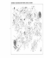
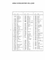
Ref.
No.
PartNo.
1.
2.
1072704
1040178
3.
4.
5.
6.
7.
8.
9.
10.
11.
12.
13.
14.
15.
16.
1072044
1039895
1073038
1071358
1072703
G120377
1016114
1072706
1035066
1017779
1071215
1039895
1035081
G453674
19.
20.
21.
22.
23.
24.
G126422
1048215
1005813
1037222
1072646
1017783
26.
27.
28.
29.
30.
31.
32.
33.
34.
35.
36.
37.
38.
39.
40.
41.
42.
1072649
1072708
1072652
1072654
1072657
53997
1072042
1072156
1072157
65139
1008523
G122052
1071305
1072695
1037035
1072618
1040101
tk---~
2.5--~_
Part Name
Body Assembly
Transmission Assembly
(see page 16 and 17)
Carriage Bolt, Y,6-18 x 1
Lock Nut, Y,6-18
Rear Cover
Machine Screw, %-20 x 1/2
Self-Tap Screw, %-20 x %
Nut, 3/8-16
Knob
Jackshaft
Bearing
Retaining Ring
Carriage Bolt, Y,6-18 x 311Lock Nut, Y,6-18
Sprocket, 10 Tooth
Roll Pin, 1j, x 1%
Chain, 67 Pitches (incl. Ref. #18)
Connector Link
Carriage Bolt, %-16 x 2%
Nylon Idler
Washer, 2~4 x 1 X t3,
Lock Nut, 3/a-16
Clutch Spool
Key, K6 x 1
Sprocket Assembly, 16 Tooth
Impeller Chain Guard
Clutch Cover
Clutch Bracket
Clutch Fork Assembly
Spring
Roll Pin, Va x 34
Axle and Sprocket Assembly
Tire
Rim
Valve Stem and Cap Assembly
Washer, 21j, x 1.12 x .061
Hex Bolt, Y,6-18x 1%
Lock Nut, Y,6-18
Chain, 53 Pitches (inc!. Ref. #40)
Connector Link
Skid
Carriage Bolt, 3/8-16 x %
Ref.
No.
43.
44.
45.
46.
47.
48.
49.
50.
51.
52.
53.
54.
55.
56.
57.
58.
59.
60.
61.
62.
63.
64.
65.
66.
67.
68.
69.
70.
71.
72.
73.
74.
75.
76.
77.
78.
79.
80.
81.
82.
83.
84.
PartNo.
1072269
1040103
1036356
1072709
1071221
1071045
10726.li2.
1037035
1072663
1051891
1073021
1072195
1071780
1072664
1072665
1072666
1073020
4933H
G120918
1071272
1072683
1072672
1072669
59309
50806
13257
1072674
1072699
1072698
1072677
1072884
1072878
58715
G120706
1071799
1071092
1072715
1072684
1072685
54138
Part Name
Scraper Bar
Carriage Bolt, V2-20 x V2
Lock Nut, %-20
Impeller Assembly
Impeller Tube Insert
Impeller Shaft
Chain, 73 Pitches (incl. ref. #50)
Connector Link
Engine, 7 H.P. Model 143.666302
PulleY,2W'
Set Screw, Y,6-18x 3/8
Thrattle Contra I
Carriage Bolt, Y,6-24x 1, Gr. 5
Lock Nut, Y,6-24
Pulley, 6"
V-Belt
Idler Bracket Assembly
Spring
Idler
Hex Bolt, 3/8-16 x 1V2
Lock Nut, %-16
Grip
Belt Guard Assembly
Escapement Assembly
Hex Bolt, Y,6-24x %
Washer, .328 x .750 x .063
Lock Washer, Y,6
Safety Switch
Electrical Wire Assembly
(Comes with 1073040)
Grommet
Belt Cover
Chute Assembly
Hand Guard
Deflector Assembly
Handle Knob
Hex Bolt, %-20 x V2
Chute Slide
Impeller Protection Bar
Data Plate
Safety Lever
Safety Lever Spring
Hex Bolt, %-20 x 2
Ref.
No.
Part No.
85.
86.
87.
88.
89.
90.
91.
92.
93.
94.
95.
96.
97.
98.
99.
100.
101.
102.
103.
104.
105.
106.
107.
108.
109.
110.
111.
115.
117.
118.
119.
1036356
1072686
1072687
1072688
9416639
1072983
1071801
1072717
1072689
1072690
1035717
1072286
1071886
1039943
1037222
1039966
1039969
1071725
1072614
1072693
1071840
1040011
G181635
1071797
1071358
1071270
1072653
1051398
1072879
1072822
1072833
120.
121.
122.
123.
124.
125.
126.
127.
128.
129.
1072835
1072836
1072837
1072838
1072839
1072840
1073040
1073043
1072718
Part Name
Lock Nut, %-20
Back Plate
Contact Plate
Bushing
Machine Screw, #10-16 x .75
Cable Tie
Control Rod Assembly
Handle Plate
R.H. Handle
L.H. Handle
Grip
Lower Support Bracket
Chute Control Assembly
Carriage Bolt, Y,6-18 x 1%
Lock Nut, 3/a-16
Knob
Spring
Formed Washer
Eye Bolt
Rubber Bushing
Grip
Transmission Control Bracket
Hex Bolt, %-24 x 311-, Gr. 5
Lock Nut, %-24
Machine Screw, %-20 x 1/2
Tire Chains
Clutch Lever
Engine Spacer (5 H.P. units only)
Hex Bolt, %-20 x 1jz
Knob
Key Switch Assembly
(Incl. Ref. No. 120 to No. 125)
Switch
Machine Screw
Clamp Washer
Lock Washer, Internal Tooth
Jam Nut
Key Assembly
Connector (Comes with 1073040)
Electrical Wire
Electrical Wire
Owner's Manual (Not shown)
Ref.
Part
No.
No.
1
2
3
4
5
6
7
8
9
10
11
12
13
14
15
16
17
18
19
20
21
22
23
24
25
180122
1036356
1035343
1039948
120392
1039927
1037222
126325
1035268
177923
137133
446161
1040008
1035275
1039930
1040009
1035281
180020
6598
1035624
70940
1035610
5430
1035599
120706
Part Name
*Bolt, Hex 3/8-16 x 1
Nut, Hex Lock (Special) 1/4-20
Support Lever - Shift
Bracket· Mounting· L.H.
*Washer 9/32-5/8 x 1/16
Bracket Assembly Support
Nut, Lock 3/8 -16
Bolt, Rd. Head Sq. Neck
1/4 -20 x 1 1/4
Pivot - Bell Crank
*Cotter Spring 1/8 x 3;4
*Pin - Cotter 1/16 x 7/16
*Washer, 7/32-7/16 x 3/64
Bell Crank
link Assembly
Spacer
Rod - Shifter
Arm - Shifter
*Bolt, Hex 1/4-20 x 3/4
Ring· Snap
Sprocket
Ball - Plain 1/4
Spring
Ring - Snap
Washer 21/32-1 x 1/32
*Bolt, Hex 1/4-20 x 1/2
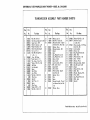
Ref.
Part
No.
No.
26
27
28
115109
120854
1035625
29
30
31
32
33
3435
36
37
38
39
40
41
1035617
1035626
1035619
1035606
1040157
1040156
1035604
1035603
1035344
42
43
44
45
1035617
1035612
1035614
1035601
46
1035602
456174
1035621
1035620
1035616
Ref.
Part Name
*Washer, Lock 1/4
* Bolt, Hex 1/4-20 x 5/8
Housing Assembly - 2-Speed
Side (Incl. Ref. #29 and 30)
Bearing - Sleeve
Bearing Assembly - Ball
Gasket
Gear
Key, Woodruff 3/16 )( 7/8
Key, Woodruff 1/8 x 5/8
Sleeve. Clutch
Gear - Clutch
Lever Assembly - Shifter
*Pin • Cotter 1/8 x 1
Countershaft
Fork - Shifter
P late Assembly - Adapter
(Inc I. Ref. #42)
Bearing - Sleeve
Gear
Spacer
Housing Assembly - Forward
and Reverse Side (Incl. Ref.
il46)
Bearing - Sleeve
No.
Part
No.
47
48
1071088
1040179
49
1071842
50
51
52
53
54
55
56
57
58
59
60
61
62
63
64
65
66
1071461
1035740
124544
1035623
1035627
1035622
1035607
1035618
53490
1040153
1035611
1035613
1035596
1035608
1040158
1035609
1035083
Part Name
Washer 9/16-9/32 x .134
Bolt, Hex, Special
1/4-20 x 3 3/4
Chain Assembly - 101 Pitches
(lncl. Ref. #50)
link Assembly
Grease - Can
*Key, Woodruff 3/32 x 5/8
Shaft - Drive
Washer 21/32-1 x 1/64
Gea r - 13 Tooth
Beari ng - Thrust
Bearing Assembly - Needle
Nut, Hex Lock 1/4-20
Gasket
Washer 21/32-1 )( 3/64
Shaft - Idler
Bracket. Mounting - R.H.
Fork· Shifter
Key, Woodruff 3/16 x 3/4
Shaft - Input
Sprocket
I
I
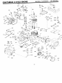
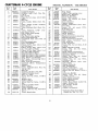
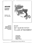
CRAFTSMAN 4-CYCLE ENGINE
1-35
I
i!Il
..--29
I
I
I
158'-~
117-~
158 --~
~..
O·
~
~«,,\\58
"
®/--82
0-81
118
"
158
116
CRAFTSMAN 4-CYCLE ENGINE
Ref.
No.
Part
No.
Part Name
1
2
666302
32586B
Complete Engine
Cylinder Assy. (Incl. Nos. 2A,
2A
3
27652
27642
Pin, Dowel
Plug, Sq. hd. pipe, 1/4-18 (Oil
drain)
Seal, Oil
Valve, Intake (Std.) (lncl. No.
3
32630
32783
Ref.
No.
33636
*27896
28423
28424
28425
650128
& 4)
27627
*27915
30195A
9)
32784
27878A
Part
No.
Valve, Intake (1/32" oversize)
(Incl. No.9)
Valve, Exhaust (Std.) (lnel. No.
9)
27880A
27882
27881
32581
650662
32680A
29783
27884
32592
32593
32594
32595
32596
32597
27888
32591C
32590
32115
34034
31303B
28427
31297
*30684
650764
650488
650691
33876
650489
*32631
30938A
30939A
650697
610118
Valve, Exhaust (1/32" oversize) (Incl. No.9)
Cap, Upper valve spring
Spring, Valve
Cap, Lower valve spring
Bolt, Connecting rod
Crankshaft Assy. (Incl. Nos. 12
& 13)
Pin, Crankshaft gear
Gear, Crankshaft
Piston & Pin Assy. (lncl. 2 of
No. 16) (Std.)
Piston & Pin Assy. (Incl. 2 of
No. 16) (.010 oversize)
Piston & Pin Assy. (Incl. 2 of
No. 16) (.020 oversize)
Ring Set, Piston (Std.)
Ring Set, Piston (.010 oversize)
Ring Set, Piston (.020 oversize)
Ring, Piston pin retaining
Rod Assy., Connecting (Incl.
Nos. 10 & 18)
Plate, Lock & Oil dipper
Camshaft (Mech. Compression
Release)
Lifter, Valve
Cover, Cylinder (lncl. Nos. 24,
106 & 147)
Seal, Oil
Dipstick, Oil (Incl. No. 88)
Gasket, Cylinder cover
Nut, "u" Type
Screw, Hex hd. Sems, 1/4-20 x
1-1/4
Washer, Flat
Gasket, Stator
Screw, Hex hd. Sems, 1/4-20 x
5/8
Gasket, Cylinder head
Head, Cylinder
Cover, Cylinder head
Screw, Hex hd. cap, 5/16-18 x
2-1/2
Cover, Spark plug
30969
30968
34144
32326A
30205
30826
30824
30699C
30700
650494
64
65
29536
650561
66
67
68
68A
31714
34126
28545
650643
29747A
32158C
650490
8116
*31688
29752
650665
34174
650572
34132
32410
29642
29826
29216
30590A
*29673
Plug, Spark
Gasket, Valve spring cover
Body Assy., Breather
Element, Breather
Cover, Valve spring
Screw, Fil. slotted hd. Sems,
10-24 x 1/2
Tube, Breather
Gasket, Intake
Flange, Carburetor (Incl. Nos.
77 & 80)
Screw, Fil. hd. macho PCR,
5/16-18 x 3/4
Cap, Oil drain
Nipple, Oil drain
Decal, Primer
Lever, Governor
Bracket, Governor adjusting
Spring, Extension
Link, Governor-to-throttle
Rod Assy., Governor (Incl.
Nos. 62 & 63)
Yoke, Governor
Screw, Phil. fil. hd. Sems, 6-40
x 5/16
Baffle, Blower housing
Screw, Phil. hex hd. Sems,
1/4-20 x 5/8
Decal, Name & Instruction
Bracket, Grommet mounting
Grommet, Plastic
Screw, Phil. pan hd. thread
forming, 8-18 x 3/8
Screw, Hex hd. cap Sems,
5/16-24 x 3/4
Housing, Blower (Incl. Nos.
135 & 136)
Washer, Belleville
Nut, Crankshaft
Gasket, Carburetor
Nut & Lockwasher, 1/4-28
Screw, Hex hd. Sems, 1/4-14 x
7/8
Deflector, Muffler
Screw, Phil. flat hd. Sems,
1/4-28 x 1-1/8
Plate, Choke indicator
Knob, Speed control
Ring, Retaining
Screw, Hex slotted washer hd.
mach., 10-32 x 3/4
Nut, Square, 10-32
Washer, Flat
Gasket, Oil dipstick
*Indicates Parts Included in
Gasket Set, Ref. No. 169.
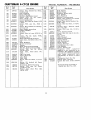
CRAFTSMAN 4-CYCLE ENGINE
Ref.
No.
Part
No.
28942
27793
34129
32398
28820
34217
650257
650760
100
102
103
104
29538
*27930
32401
650694
106
107
31845
30591
108
109
110
111
112
113
29193
30588A
26073
34159
34158
650561
Ref.
No.
Screw, Hex slotted hd. Sems,
10-32 x 3/8
Clip, Conduit
Decal, Warning
Bracket, Carburetor cover
Screw, Phil. fil. hd. macho
Sems, 10-32 x 1/2
Cover, Carburetor
Screw, Phil. pan hd. Sems, 8-32
x 5/16
Screw, Phil. pan hd., 8-32 x
7/16
Screw, Hex washer hd. self-tap,
12-14 x 5/8
Base, Engine mounting
Gasket, Muffler
Muffler
Screw, Hex hd. cap, 5/16-18 x
2
Screw, Fil. hd. macho PCR,
5/16-18 x 3/4
Shaft, Mechanical governor
Gear Assy., Governor (Incl. No.
87)
34156
115
116
117
118
119
34210
32961
29774
30705
650665
120
650128
121
122
30622
29716
32182
125
126
127
128
129
130
131
Part
No.
32183
32184
32312
32180A
32589
31843A
28763
132
650548
133
650493
134
33108
650736
136
144
33013
650542
145
146
147
152
154
156
158
162
163
164
166
31291
34131
31546
31680
32576
34133
26460
29918
32125
590417
610694A
Ring, Retainer
Spool, Governor
Washer
Plate, Fuel tank mounting
Bracket, Fuel tank mounting
Screw, Phil. hex hd. Sems,
1/4-20 x 5/8
Tank Assy., Fuel (Incl. No.
115)
Cap, Fuel tank
Valve, Shut-off
Line, Fuel
Line, Fuel
167
Screw, Hex hd. Sems, 1/4-14 x , 168
169
7/8
Screw, Fil. slotted hd. Sems,
10-24 x 1/2
Extension, Blower housing
Screw, Phil. pan hd. Sems,
1/4-28 x 7/16
Primer Assy. (Incl. Nos. 125,
126 & 127)
631920
590473
33239
Bulb, Primer
Body, Primer
Retainer, Primer bulb
Line, Primer
Key, Flywheel
Bracket, Governor gear
Screw, Hex washer hd. thread
forming, 10-24 x 1/2
Screw, Hex slotted washer hd.,
8-32 x 3/8
Screw, Hex hd. Sems, 1/4-20 x
1-3/4
Control Assy., Remote speed
(Incl. No. 56)
Screw, Phil. pan hd., 10-16 x
3/8
Cover, Starter bubble
Screw, Hex hd. cap, 5/16-18 x
13/16
Plug, Cover
Wire, Ground
Bushing, Crankshaft
Guard, Starter
Seal, Snow guard
Decal, Choke
Clamp, Fuel line
Lockwasher, No.8 E.T.
Cup, Starter
Screen, Starter cup
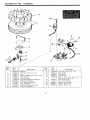
Magneto
(The
complete
magneto is not available as an
assembly. The magneto number
is shown for reference purposes
only. Order component parts
individually, as shown in parts
list.)
Carburetor (Incl. No. 75)
Starter Assy., Rewind
Gasket Set (Incl. items marked
*)
*Indicates Parts Included in
Gasket Set, Ref. No. 169.
The complete magneto is
not
available
as
an
assembly.
The magneto
number is shown for reference purposes only. Order
component parts individually. as shown in parts list.
17
r
2
~
I
(9-3
I
I
I
I
18
d
I
I
I
I
I
)
...•.
/
/
/
6
7 \
8~~
Ref.
No.
1
lA
2
3
4
5
6
7
8
9
10
Part
No.
610694A
30811A
610934
30551
610947
30992
30547A
610385
33356
610408
29181
610593
Part Name
Magneto
Flywheel (Incl. No.IA)
Fan
Spring, Breaker box dust cover
Cover, Dust
Cam, Breaker
Contact Assembly, Breaker
Washer, Terminal
Tab, Ground terminal
Nut, Terminal
Screw & Washer, Breaker
Screw, Condenser
Ref.
No.
11
12
13
14
15
16
17
18
19
19
Part
No.
30560A
30554
30548A
30545
30561B
30549
31311
29629
610955
610956
Part Name
Coil Assy. (Incl. No. 12)
Wire, Lead
Condenser
Core & Plate
Stator Assy. (Incl. Nos. 2, 3, 5
thru 14 & 16 thru 19)
Felt, Cam wiper
Clip, Coil locking
Spring, Coil wedge
Gasket, Dust cover
Gasket, Dust cover
,-.. •..•..
I
I
•..
I
I
I
I
I
I
I
I
I
I
I
I
@_16
I
I
21-@
I
~
Ref.
No.
Part
No.
1
2
3
4
5
6
7
8
9
10
11
12
631920
31834
630731
631036
650506
630766
650417
631913
630739
631815
*630748
*631027
*631021
13
631022
Part Name
Carburetor
Shaft & Lever Assy., Throttle
Spring, Throttle return
Shutter, Throttle
Screw, 4-40 x 3/16
Spring, Idle regulating screw
Screw, Idle regulating
Shaft & Lever Assy., Choke
Washer, Flat
Shutter, Choke
Plug, Welch
Plug, Welch
Inlet Needle, Seat & Clip Assy.
(Inc!. No. 13)
Clip, Inlet needle
Ref.
No.
Part
No.
14
15
16
21
22
631023
*631024
631867
27110
*31839
23
24
25
26
30
31
32
*630740
*631078
*631028
631803
630738
630735
31840
Part Name
Float, Carburetor
Shaft, Float
Bowl, Float
Gasket, Bowl-to-body
Adjustment Screw Assy., Main
(Inc!. Nos. 8, 21, 23 & 30)
"0" Ring, Adjustment screw
Screw, Idle adjustment
Gasket, Bowl-to-body
Fitting, Fuel inlet
Spring, Main adjustment screw
Spring, Choke stop
Repair Kit (Inc!. items marked
*)
Ref.
No.
1
2
3
4
5
6
Part
No.
590473
590409
590474
590411
590148
590475
590478
Part Name
Starter, Rewind
Screw, Retainer
Cam, Dog
Spring, Brake
Dog, Starter
Spring, Dog
Pulley
Ref.
No.
7
8
9
10
11
12
13
Part
No.
590414
590415
590386
590387
590459
590476
590477
Part Name
Spring & Keeper Assembly
Housing Assembly, Starter
Rope, Starter
Handle Assembly, Starter
Pin, Centering
Retainer, Dog
Screw, No.6 x 5/16
IsearsJ,
owner s
manual
The Model Number will be found on a plate attached to the
rear of the housing and engine base assembly. Always mention the Model Number when requesting servic~ or repair
parts for your SNOW THROWER.
All parts listed herein may be ordered through SEARS
ROEBUCK AND CO. or SIMPSONS-SEARS LIMITED. When
ordering parts by mail, selling prices will be furnished on
request or parts will be shipped at prevailing prices and you
will be billed accordingly.
When ordering repair parts, always give the following
mation as shown in this list.
1. The PART NUMBER
2. The PART DESCRIPTION
3. The MODEL NUMBER 4. The NAME OF ITEM -
C944.526460
22" SELF-PROPELLED
SNOW THROWER
5. The ENGINE MODEL NUMBER -143.666302
MODEL NO.
C944.526460
infor-