1
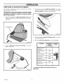
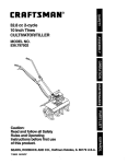
Operator's
Manual
I CRAFTSM RN°I
. _a,et_
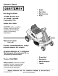
Mid-Engine Rider
• Operation
• Maintenance
• Parts
13.5 HP. Electric Start
30" Mower / Mulcher
5 Speed Transaxle
Model 536.270290
CAUTION: Before using this
product, read this manual
and follow all of its Safety
Rules and Operating
Instructions.
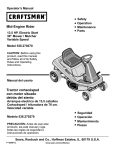
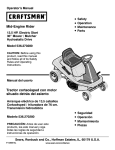
Manual del usario
Tractor cortacesped con motor
situado detras del asiento
Arranque electrico de 13,5 caballos
Cortacesped / trituradora de 76 cm.
Transaxle de 5 velocidades
• Seguridad
Modelo 536.270290
PRECAUCION:
Antes de usar este
• Operacion
• Mantenimiento
• Piezas
producto, lea este manual y siga
todas las reglas de seguridad e
instrucciones de operaci6n.
Sears, Roebuck and Co., Hoffman Estates, IL. 60179 U.S.A.
F-040607L
www.sears.com/craftsman
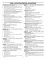
TABLE OF CONTENTS
WARRANTY
....................................
2
MAINTENANCE
3
SERVICE AND ADJUSTMENT
....................
24
SAFETY RULES .................................
4
TROUBLE SHOOTING CHART ....................
32
PREPARATION
7
SLOPE GUIDE
..................................
35
10
REPAIR PARTS
.................................
36
PRODUCT SPECIFICATIONS
OPERATION
.....................
..................................
....................................
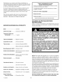
LIMITED
WARRANTY
ON CRAFTSMAN
.................................
RIDING
18
EQUIPMENT
I I
I I
For two (2) years from the
according
to the instructions
I iI
I I
defective in material or workmanship
according
to the guidelines
of coverage
listed below.
Sears will also provide free labor for these applicable warranted
parts for the two full years. During the first 30 days of purchase,
I
I
I
I
there will be no charges to service the product at your home
For your convenience,
IN HOME warranty service will still be
apply. This charge will be waived if the Craftsman
product
authorized
Sears location, please call 1-800-4-MY-HOME,:R_,.
I
I
I
I
II
States.
I I
This Warranty
I I
•
I I
for issues covered by this warranty. (See exclusions
below).
available after the first 30 days of purchase, but a trip charge will
is dropped off at an authorized
Sears location.
For the nearest
This warranty applies only while this product is within the United
does not cover:
Expendable
belts,
date of purchase,
if this Craftsman
Riding Equipment
is maintained,
lubricated
and tuned up
in the owner's manual, Sears will repair or replace free of charge any parts that are found to be
items which
become
worn during
normal
use, including
Servicing,
oil changes,
or tune-ups
but not limited
to blades,
spark
plugs,
air cleaners,
and oil filters.
I I
•
Standard
I I
•
Tire replacement
I I
•
Repairs
•
capability
of the riding equipment,
impacting
objects that bend the frame or crankshaft,
or over-speeding
the engine.
Repairs necessary because of operator negligence,
including but not limited to, electrical and mechanical
damage caused
by improper storage, failure to use the proper grade and amount of engine oil, failure to keep the deck clear of flammable
I I
I I
I I
I I
I I
•
I I
I I
•
II
Maintenance
or repair
necessary
caused
because
by punctures
of operator
from outside
abuse,
including
caused
stumps
or glass.
by towing
objects
or failure to maintain the equipment
according
to the instructions
contained
in the owner's
(fuel system) cleaning or repairs caused by fuel determined
to be contaminated
or oxidized
should
be used within
Normal
deterioration
equipment
30 days of its purchase
and wear
of the exterior
used for commercial
WARRANTY
finishes,
or rental
LIMITED
I I
For ninety
I I
I I
workmanship
and our testing determines
the battery
the first 30 days of purchase, there will be no charges
I I
I I
nience,
product
I I
HOME_,,','. This Warranty
(90) days from
beyond
manual.
(stale). In general,
the
fuel
date.
I I
or product
label replacement.
purposes.
ON BATTERY
date of purchase,
if any battery
included
with this riding
equipment
proves
defective
in material
or
will not hold a charge, Sears will replace the battery at no charge. During
to replace the battery at your home. After the first 30 days, for your conve-
IN-HOME warranty service will still be available but a trip charge will apply. This charge will be waived if the Craftsman
is dropped off at an authorized
Sears location.
For the nearest authorized
Sears location, please call 1-800-4-MYapplies
and you may also have other
F-O40607L
such as nails, thorns,
debris,
Engine
Riding
L.L_
objects,
but not limited to, damage
only while this product
rights, which
Sears,
Roebuck
vary, from
is within
the United
States.
This warranty
gives you specific
state to state.
and Co., Dept.
817WA,
2
Hoffman
Estates,
IL 60179
legal rights,
Congratulations
onyourpurchase
ofa Craftsman
Mid-Engine
Rider.
Ithasbeendesigned,
engineered
andmanufactured
to
giveyouthebestpossible
dependability
andperformance.
Ifyouexperience
anyproblems
youcannot
easilyremedy,
please
seeyournearest
SearsService
Center.
Wehavecompetent,
well
trained
technicians
andtheproper
toolstoservice
orrepairthis
unit.
Please
readandkeepthismanual.
Theinstructions
willenable
youtoassemble
andmaintain
yourunitproperly.
Always
observe
the"Safety
Rules".
Mid-Engine
Craftsman
Record in the space below
of purchase of this unit.
the serial
The model number and serial
attached to the unit.
Rider
number
number
and the date
are found on a decal
Model Number: 536.270290
Serial Number:
Date of Purchase:
Keep these
PRODUCT
Engine
..................
Charging
REPAIR
SPECIFICATIONS
Type of Fuel
Unleaded Regular
.............
..............
Above
..........................
32 degrees
Below 32 degrees
(Gap 0.030")
..
Champion
Front 22 psi (See tire sidewall)
Tire Air
Pressure
.........
Rear 14 psi (See tire sidewall)
Speed
............
Range
NOTE:
Forward
5.0 mph
..........................
Reverse
2.5 mph
This unit is equipped
Tilt
Access
.................
Housing
..........
to engine
and battery.
Blade
Height
Nut Torque
F-040607L
...........
Full-fl0ating suspension, one blade.
.........
6 positions
from
30 foot-pounds
in effective
have similar
laws.
Service
In some areas,
to control
Cutting
combustion
engine
working
order
local
by the operator.
In the State of California, the above is required by law (Section
4442 of the California Public Resources
Code). Other states may
Sears
Mower
with an internal
system is equipped with a spark arrester meeting applicable
or state laws (if any). If a spark arrester is used, it must be
maintained
Seat
repro-
and must not be used on or near any unimproved
forest-covered,
brush-covered
or grass-covered
land unless the engine's exhaust
Hydrostatic
.....
or other
cancer and birth defects or other reproductive
harm. WASH HANDS AFTER HANDLING.
RJ4C
.........
Ground
unit. See the
Battery posts, terminals and related accessories contain lead and lead compounds,
chemicals known to the State of California to cause
SAE 5W30
Pressure
System
cause cancer and birth defects
ductive harm.
SAE 30
Tire Air
Drive
on this
Engine Exhaust, some of its constituents,
and
certain vehicle components
contain or emit
chemicals
known to the State of California to
48 ounces (3 pints)
.................
Plug
AGREEMENT
3 amperes at 3600 rpm
1.1 gallon
Spark
PROTECTION
reference.
A Repair Protection Agreement
is available
nearest Sears Store for information.
Fuel Tank Size ...........
Oil Type
for future
13.5 HE
System .........
Oil Capacity
numbers
lb2 to 4 inches.
resistor
Federal
Center
local law requires
the ignition
spark
signals.
3
on federal
arrester
lands.
the use of a resistor
See a Sears
See a
for the muffler.
Service
spark
Center
plug
for a
plug for the engine.
NOTE: Actual sustained
to operating
limitations
(ft-lbs)
laws apply
for a spark
horsepower
will likely be lower due
and environmental
factors.
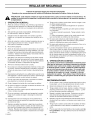
SAFETY RULES
Safe Operation
Practices for Ride-on Mowers
WARNING:
This cutting
machine
is capable
amputating
and feet and throwing objects. Failure to observe the
following safety
instructions
could
result inofserious
injury hands
or death.
I.
1.
General
operation
Read,
understand
Book,
on the machine,
21
and follow
all instructions
mower
serious
be-
fore starting.
2.
Only allow responsible
adults, who are familiar
tions, to operate the machine.
with the instruc-
3.
Clear the area of objects such as rocks, toys,
could be picked up and thrown by the blade.
wire, etc., which
4.
Be sure the area is clear of other
before
mowing.
the machine
if anyone
5.
Never
passengers.
6.
Turn off power to the blades or any attachments
before
up. Do not mow in reverse unless absolutely necessary.
carry
look down
7.
and behind
9.
11.
the area.
Slow down
before
before
and while
backing
Always
backing.
guard
the key before
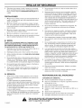
Slopes
control
before
Do not operate
removing
the grass
or good artificial
the machine
while
and others
from
and rough terrain are major factors
related to loss-ofand tip-over accidents,
which can result in severe inju-
Guide"
in the back
of this book to check
for
1.
Mow
2.
Remove
or not in use.
bagger
or unclog-
light.
up and down slopes,
3.
Watch for holes, ruts or bumps. Uneven terrain
the machine.
Taft grass can hide obstacles.
4.
Follow
obstacles
the manufacturer's
or counterweights
not across.
such as rocks,
limbs, etc...
recommendations
to improve
for wheel weights
Use extra care with grass baggers or other
can change the stability of the machine.
6.
Keep
7.
overturn
stability.
5.
all movement
could
on the slopes
in speed
slow
and
attachments,
gradual.
they
Do not
make sudden
changes
or direction.
Avoid starting
off the blades
or stopping on a slope. If tires lose traction, turn
and proceed slowly straight down the slope.
DO NOT
under the influence
of alcohol
Do not turn on slopes unless absolutely necessary, then only
turn slowly and gradually downhill, if possible.
2.
Do not mow drop-offs, ditches or embankments. A wheel over
the edge or an edge caving in could cause a sudden overturn
and an injury or death.
3.
Do not mow on wet grass. Reduced traction could cause sliding.
4.
Do not try to stabilize the machine by putting your foot on the
ground.
that can be thrown from the unit. Always wear eye protection
when you make an adjustment
or repair to the machine.
5.
Do not use a grass bagger or other rear mounted accessories
on steep slopes (greater than 10 degrees).
Use care when
III. Children
or when
very tired.
14.
Watch
15.
Use extra caution
a trailer or truck.
16.
Disengage
all attachment
attempting
to start the engine.
Always
for traffic when
wear
you operate
18.
themselves
1.
or drugs
17.
to protect
DO
ging the chute.
13.
are in-
ry or death. ALL slopes require extra caution.
If you cannot
back up the slope or if you feel uneasy on the slope, do not mow
dismounting.
Turn off power to attachment(s)
when transporting
Turn off the blade(s) when not mowing.
Mow only in daylight
age 60 years and above,
II. Slope operation
in place.
turning.
12.
safely enough
injury.
it. See the "Slope
Never leave a machine unattended
with the engine running. Always turn off the blade(s),
set the parking brake, stop the en-
Stop the engine
that operators,
safe operation.
or the mower
gine and remove
10.
Stop
Be aware of the mower discharge
direction and do not point it
at anyone. Do not operate the mower without either the entire
grass bagger
8.
enters
people
indicates
volved in a large percentage
of riding mower related injuries.
These operators should evaluate their ability to operate a riding
in the Instruction
the engine and with any attachments
Data
operating
when
goggles,
loading
or unloading
clutches
safety
the unit to protect
pulling
near or crossing
loads
roadways.
the machine
and shift into Neutral
glasses,
or an eye shield
your eyes from
or using
heavy
foreign
into
before
when
objects
equipment.
a. Use only approved drawbar
hitch points.
b. Limit loads to those you can safely control.
c. Do not turn sharply. Use care when
d. Use counterweights
or wheel weights
Instruction
Book.
backing.
when suggested
in the
19.
Do not operate this machine if you are taking drugs or other medication which can cause drowsiness
or affect your ability to operate this machine.
20.
Do not use this machine
to operate this machine
F-040607L
if you are mentally
safely.
or physically
unable
Tragic accidents can occur if the operator is not alert to the
presence of children. Children are often attracted to the machine and the mowing activity. NEVER assume that children
will remain where you last saw them.
1. Keep children out of the mowing area and in the watchful care
of another responsible adult.
2,
Be alert and turn the engine off if children enter the area.
3.
Before and when backing, look behind and down for small
children.
SAFETY RULES
4.
Never
carry
off. They
children
the safe operation
5,
Never
allow
even with the blades
injured
or interfere
6.
with
of the machine.
children
in the potential
6.
or any passengers,
may fall off and be seriously
to operate
dangers
7.
the machine.
Instruct
children
blind corners,
vision.
shrubs,
8.
Use extra
Grass
care when
handling
gasoline
and other
fuels.
Fuels
ing. Do
c. Never
not smoke.
refuel the machine
d. Never
store the machine
er inside where there
bagger
2.
Never
3.
Keep all nuts and bolts,
11.
such as a water heater.
inside a closed
especially
the blade
area.
attachment
check
Wait for all movement
unit.
•
Use only unleaded
•
Service
the air cleaner
•
Change
oil regularly.
leaves
•
Tune-up
the engine
or other debris build-up. Clean up oil or fuel spills. Allow the machine to cool before storing.
•
Keep equipment
•
Dispose
in good condition.
Check their proper
oper-
ation regularly.
To reduce
fire hazards,
Do not
the en-
damage
and
and replace
with man-
necessary.
and can cut. Wrap the blade(s) or
caution when servicing them or the
frequently.
Adjust
and service as re-
keep the machine
free of grass,
5
servicing
fuel tank completely
fuel for off-season
full.
storage.
gasoline.
regularly.
Use 30W oil in summer.
regularly.
in efficient
of used engine
precautions.
symbol
indicates:
"Attention!
Look for this This
symbol
to indicate
important
safety
Become Alert! Your Safety Is At Risk."
F-040607L
to wear,
Awareness
Drain
devices.
or over-speed
OF THE OWNER
Do not fill the engine's
with the safety
parts when
to stop before
•
tamper
running.
running.
area.
•
Never
settings
components
the brake operation
Environmental
immediately
replaced with an original equipment blade from an
authorized
service dealer. For safety, replace the blade every
Keep the equipment
with the engine
with the engine
are subject
recommended
RESPONSIBILITY
nuts
tight. Frequently
check the blade(s) for wear or damage such
as cracks and nicks. A blade that is bent or damaged
must be
two years.
Repair,
quired.
indoors.
start or run the engine
governor
components
Frequently
Check
an object.
which could expose moving parts or allow objects
For storage, always make sure the grass bag is
blade housing
with fuel in the tank or fuel contain-
is an open flame,
or repairs
can be adjusted
Mower blade(s) are sharp
wear gloves and use extra
10.
if you strike
restarting.
the engine
ufacturer's
b. Never remove the gas cap or add fuel with the engine running. Allow the engine to cool for several minutes before refue!-
5.
adjustments
make
empty.
are flammable
and the vapors are explosive.
a. Use only an approved
container.
4.
Never
deterioration,
to be thrown.
IV. Service
1.
before
change
gine.
trees
the equipment
if necessary,
The carburetor
of the machine.
Use extra care when approaching
or other objects that may obscure
Stop and inspect
operating
oil properly.
condition.
any part of the
SAFETY RULES
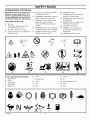
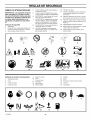
INTERNATIONAL
PICTORIALS
IMPORTANT: Some of the following pictorials are located on your unit or on
literature supplied with the product. Before you operate the unit, learn and understand the purpose for each pictorial.
Warning
2
Shield
Eyes.
Cause
Blindness
Explosive
Gases
3
No Sparks,
Flames
4
Sulphuric Acid Can Cause
Or Severe Burns
6
8
Blindness
9
Read
Operating
Owner's
This Machine.
Thrown
Bystanders
Away.
Instructions
Machine.
Before
WARNING:
Do Not Use This Machine
Greater
DANGER:
Objects.
Read
Keep People,
Away
DANGER: No Step.
11
DANGER: Keep Feet And Hands
Away From Rotating Blade,
12
DANGER: Keep Hands Away From
Rotating Blade,
13
14
DANGER: Disconnect Spark Plug
Wire Before Servicing Unit.
WARNING: Hot Surface,
15
WARNING:
Keep
User
Operating
Than
10
Manual
WARNING:
Children,
2
With Water.
Help Fast.
IMPORTANT:
On Slopes
or Smoking.
1
Eyes Immediately
Before
Can
Or Injury.
Flush
Get Medical
7
Safety Warning Pictorials
1
5
This
15 Degrees.
Especially
16
From Unit.
WARNING: Crushed Fingers.
6
3
7
8
9
12
13
14
10
MAX± 90N
Control
And Operating
Use Caution When
Connecting Or Disconnecting
Accessories,
MAX± 150N
15
16
6
Brake
11
Choke
1
Engine Start
7
Parking Brake
12
Oil
2
3
4
Lights
Engine Stop
Engine Stop
8
Clutch
13
Blade Rotation Control
9
Slow
14
Raise
5
Engine Run
10
Fast
15
Fue!
1
2
Pictorials
11
3
4
5
6
7
t_./
10
F-040607L
11
12
STOP
13
14
6
15
8
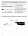
PREPARATION
PREPARATION
1.
Locate
Read
2.
Pull the tear tape no more than twelve
3.
Re-grasp
the tear tape next to the carton
4.
One the
tear tape
and follow
the
preparation
instructions
fasteners
are in the parts bag. Do not discard
until the unit is assembled.
for your
mower.
All
any parts or material
the two tear tabs at the top of the carton.
ends, remove
NOTE: In this instruction book, left and right describe the location of a part from the viewpoint of someone setting in the operator's seat.
has been
nance to theBefore
mower,doing
remove
wire from or
themaintespark
WARNING:
any the
preparation
plug.
Repeat
6.
Set the panels
7.
Move the shift lever to the neutral
the process
If the
parking
clutch/brake
9.
To remove
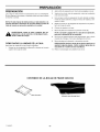
FROM THE CARTON
the unit from the carton,
follow
the instructions
LOOSE
The fasteners
and other
loose
parts are shown
below.
below.
10.
from
on the tear tabs at the bottom
The fasteners
brake
Check
the
any staples
Remove
the mower
(N) position.
section,
is engaged,
pedal to release
Remove
are shown
page 10, for the location
completely
depress
bottom
position.
of the
carton
that are in the path
from the shipping
full size. The quantity
the
the brake.
for staples.
of the tires.
skid.
is shown
in brackets
().
Side DischargeAttachment
7
both
of the carton.
PARTS - CONTENTS
LiteratureKit
F-040607L
removed
aside.
Move the lift lever to the highest
CAUTION:
HOW TO REMOVE
completely
5.
8.
and pull again.
the top wood and set aside.
NOTE: See the Operation
of the controls.
_b
inches at a time.
PREPARATION
MAINTENANCE
IMPORTANT:
FREE BATTERY
Before
the
you
battery,
check
battery
battery
must be charged.
1.
Raise the seat support
seat support rod.
2.
Check
(Figure
3.
date.
the
The
and secure
cables
If the battery
battery
cables
date
to the
tells
in the UP position
if the
Install the battery and secure with the battery retainer.
sure the positive (+) terminal is on the right side.
with the
of the battery
must
Maintenance
is put into service
before
the battery
can be attached
without
charging
is put
HOW TO INSTALL
date
THE BATTERY
Make
CABLES
be
charged.
date,
the
the
positive To
(+)prevent
terminalsparks,
before fasten
you connect
black
WARNING:
the redthe
cable
to
cable.
,_
the battery.
Cables".
into service
after
See
the battery
"How
To
date,
Charge
Use the fasteners
shown below to install the battery
fasteners
are attached to the battery cables,
the
The
cables.
(A)
2x82
FREE BATTERY
smoke.
KeepWhen
the battery
away from
sparks.
WARNING:
you charge
the any
battery,
do The
not
fumes from the battery acid can cause an explosion.
1.
To disconnect the battery retainer from the battery tray, push
in on the lower end of the battery retainer,
2.
Remove the battery from the right side of the unit.
3.
Remove the protective caps from the battery terminals.
Battery
(B)
14x79
1.
Remove the protective caps from the battery terminals.
2.
Fasten the red cable to the positive (+) terminal
fasteners as shown (Figure 1).
3.
Mount the battery
4.
Fasten the black cable to the negative (-) terminal with the
fasteners as shown.
with the
boot onto the positive (+) terminal.
A
Positive (+)
Terminal
A
Black Cable
B
Red Cable
Battery Clamp
Figure 1
F-040607L
The
Free Battery".
HOW TO CHARGE
THE MAINTENANCE
,_
Use a 12 volt battery charger to charge the battery. Charge at
a rate of 6 amperes for one hour. If you do not have a battery
charger, have a Sears or other qualified Service Center charge
the battery.
1).
See "How To Install The Battery
4.
battery
battery
the top of the battery for the location
If the battery
battery
attach
4
8
PREPARATION
HOW TO PREPARE
THE ENGINE
NOTE: The engine was shipped from the factory filled with oil.
Check the level of the oil. Add oil as needed.
Before you use the unit, read the information on safety, operation,
maintenance, and storage.
CHECK THE LEVEL OF THE MOWER HOUSING
Make sure the level of cut is still correct. After you mow a short
distance, look at the area that was cut. If the mower housing does
not cut level, see the instructions
on "How To Level The Mower
Housing"
book.
in the Service
CHECK
And Adjustment
section
of this instruction
THE TIRES
Check the air pressure in the tires. Tires with too much
will cause the unit to ride rough. Also, the wrong air
keep the mower housing from cutting level. The correct
(PSI) is as follows. Semi-pneumatic
front tires do not
Front Tires
Rear Tires
IMPORTANT!
air pressure
pressure will
air pressure
require air.
22 PSI (1.5 BAR)
14 PSI (! BAR)
BEFORE
YOU START MOWING
Check the engine oil,
Fill the fuel tank with gasoline.
Check the level of the mower housing,
Check the air pressure of the tires.
Make sure the battery cables are attached.
F-040607L
9
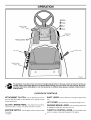
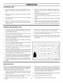
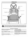
OPERATION
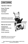
Ignition
(_
Stop
(_Run
Clutch / Brake
Pedal
Start
Attachment
Clutch
Parkiing Brake _))
Shift Lever
Lift Lever
Throttle Control
Lever
Figure 2
The operation of any lawn mower can result in foreign objects thrown in the eyes, which can result in severe eye
damage. Always wear safety glasses or eye shields before starting your lawn mower and while mowing. We recommend the Wide Vision Safety Mask for over the spectacles or standard safety glasses, available at Sears Retail or
Catalog Stores.
LOCATION
ATTACHMENT
CLUTCH:
Use the attachment
OF CONTROLS
clutch to
SHIFT LEVER:
LIFT LEVER:
CLUTCH / BRAKE PEDAL: The pedal has two functions.
The first function is a clutch. The second function is a brake.
PARKING
IGNITION
THROTTLE
the engine.
F-040607L
SWITCH:
Use the shift lever to change the speed of the
unit,
start and stop the rotation of the blade(s) and to operate a snow
thrower attachment.
Use the lift lever to change the height of cut.
BRAKE
LEVER:
Usethe
parking
brake
lever
to engage the brake when you leave the unit.
Use the ignition switch to start and stop
CONTROL
LEVER: Usethe throttle
lever to increase or decrease the speed of the engine.
10
control
OPERATION
ATTACHMENTS
This unit can use many different attachments.
This unit can pull
attachments
like a lawn sweeper, a lawn aerator, a hopper spreader,
or a small trailer. This unit can not use attachments
ground like a plow, a disk harrow, or a cultivator.
that engage
or trailer
the
For all pull-behind
attachments
or trailers,
the maximum
gross
weight is 200 pounds. Gross weight is the weight of the attachment
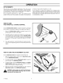
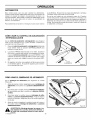
HOW TO USE
THE THROTTLE
and any load that might be on or in it.
Do not operate on a slope that is greater than 10 degrees
when
using a pull-behind
attachment
or trailer. We have included a slope
guide in this book to help you determine the slope on which you will
be operating your unit. Never allow someone to stand or ride on or
in an attachment
or trailer.
/ CHOKE CONTROL
Use the throttle/choke
control to choke the engine for cold starts
and increase or decrease the speed of the engine (see Figure 3).
1.
Move the throttle/choke
control completely forward to the
CHOKE position to start a cold engine.
2.
The FAST position
tion and when
is marked
with a detent.
using a grass bagger,
to the FAST position.
for a cooler running
For normal
move the throttle
operacontrol
For maximum
charging of the battery and
engine, operate the engine in the FAST
position.
3.
The engine
mance.
engine.
governor
is set at the factory
Do not adjust the governor
to increase
HOW TO USE THE ATTACHMENT
Use the attachment
for maximum
the speed of the
gure 3
clutch to engage the blade (Figure 4).
Before you start the engine, make sure the attachment
is in the DISENGAGE position.
2.
To rotate the blade, move the attachment
lock the blade in the ENGAGE position.
3.
To stop the blade, move the attachment clutch to the DISENGAGE position.
Before you leave the operator's position,
make sure the blade has stopped rotating.
4.
Before you ride the unit across a sidewalk or a road, move the
attachment clutch to the DISENGAGE position.
clutch
clutch
forward to
Attachment Clutch
Engage Position
from
the blade,
deflector
opening,
WARNING:
Always
keep your
handsand
andthe
feetmower
away
housing when the engine runs.
F-040607L
Throttle
Contro
CLUTCH
1.
_
,
perfor-
Figure 4
11
OPERATION
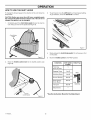
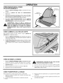
HOW TO USE THE SHIFT
LEVER
To change the forward speed or the direction of the unit, follow the
steps below.
3.
To go forward, move the shift lever to a forward speed setting.
To go backward, move the shift lever to reverse.
CAUTION: Before you move the shift lever, completely push
the clutch/brake pedal forward to stop the unit. If the unit is not
stopped, the gearbox can be damaged.
1.
Completely push the clutch/brake pedal forward to stop the
unit. Keep your foot on the pedal (see Figure 5).
Clutch/Brake
Pedal
Figure 7
Figure 5
2.
Move the throttle control lever to the SLOW position (see
Figure 6).
4.
Slowly release the clutch/brake pedal. Do not keep your foot
on the pedal.
5.
Move the throttle
control
FUNCTION
Trimming
Snow Thrower
Bagging
Grass
to the FAST
SHIFT LEVER
6 Speeds
position.
THROTTLE
1
1 or2
FAST
Mulching
Normal
Grass
Mowing
1 or2
2or3
CHOKE
FAST
m
Easy Mowing
Snow Blade
3 or4
Transport
5 or6
m
SLOW
THROTTLE
Attachments
Throttle
Control Lever
* See the Instruction Book for the Attachment.
Figure 6
F-040607L
12
OPERATION
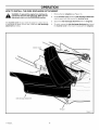
HOW TO SET THE PARKING
BRAKE
1.
Completely push the clutch/brake
2.
Lift the parking brake lever (Figure 8).
3.
Remove your foot from the clutch/brake pedal and then release
the parking brake lever. Make sure the parking brake will hold
the unit.
4.
To release the parking brake, completely push the clutch/
brake pedal forward. The parking brake will automatically release.
WARNING:
pedal forward.
Before you leave the operator's
Parking Brake
Clutch/Brake
Pedal
position,
parking
Movetothe
rotation
control Set
to the
move thebrake.
shift lever
theblade
neutral
(N) position.
the
DISENGAGE position. Stop the engine and remove
the ignition key.
HOW TO CHANGE
THE CUTTING
Figure 8
HEIGHT
To change the cutting height, raise or lower the lift lever as follows.
1.
Move the lift lever forward to lower the mower housing and
back to raise the mower housing (Figure 9).
2.
When you ride on a sidewalk or road, move the lift lever to the
highest position and move the blade rotation control to the
DISENGAGE position.
Figure 9
HOW TO STOP THE UNIT
1.
Completely push the clutch/brake
unit. Keep your foot on the pedal.
2.
Move the blade rotation control to the DISENGAGE
3.
Move the shift lever to the NEUTRAL position.
4.
Set the parking brake.
HOW TO TRANSPORT
To transport
1.
the unit, follow
Move the blade
rotation
pedal forward to stop the
_
position.
ARNING: Make sure the parking brake will hold the
unit.
5.
Move the throttle
control
to the SLOW
position.
6.
To stop the engine,
move the key.
turn the ignition key to the OFF position.
Re-
3.
Move the throttle
FAST.
control
and
4.
To go faster,
THE UNIT
the steps
control
2.
Raise the lift lever to the highest
F-040607L
below.
to the DISENGAGE
position.
position.
13
to a position
between
move the shift lever to a faster
speed.
SLOW
OPERATION
HOW TO INSTALL THE SIDE DISCHARGE
,_
ATTACHMENT
connect
theTo
wire
from the
sure disthe
WARNING:
prevent
the spark
engineplug.
fromMake
starting,
attachment clutch is in the DISENGAGE position.
The mulcher cover lets you mulch the grass for a clean, fine cut.
To discharge the grass out the side, install the side discharge
attachment as follows.
1.
Remove the two wingnuts (see Figure 10).
2.
Lift the mulcher cover. Mount the side discharge attachment
onto the same bolts that secured the mulcher cover.
3.
Secure the side discharge attachment
4.
To mulch, remove the side discharge attachment and mount
the mulcher cover to the mower housing with the wingnuts.
with the wingnuts.
Mulcher Cover
Wingnut
Side Discharge Attachment
Wingnut
Figure 10
F-040607L
14
OPERATION
BEFORE
STARTING
THE ENGINE
CHECK THE OIL
NOTE:
The engine
30 weight
1.
was shipped
oil. Check
the level
from the factory
filled with SAE
of the oil. Add oil as needed.
Make sure the unit is level.
NOTE:
runs.
Do not check
the level
of the oil while
Remove
To prevent
the engine
2.
Clean the area around the dipstick.
the oil from the dipstick.
3.
Insert the dipstick into the oil fill tube. Turn the dipstick clockwise until it is tight. Remove the dipstick. Check the oil level on
the dipstick.
system
Wipe
problems
storage
1.
Drain
2,
Start the engine.
with the fuel system,
of 30 days or longer
carburetor
Let the engine
run until the fuel lines and the
If necessary,
add oil until the oil reaches the FULL mark on the
dipstick. The quantity of oil needed from ADD to FULL is shown
4.
Never use engine cleaner or carburetor
or permanent
damage can occur.
the FULL
mark
Always
use a safety
gasoline
container.
tank
in the fuel tank
with
regular
unleaded
gasoline.
Do not use
premium
unleaded
gasoline.
Make sure the gasoline
is fresh
and clean. Leaded
gasoline
will
increase
deposits
and shorten
the life of the valves.
The factory settings for the carburetor
are for most conditions.
If the
engine is operated
under the following
conditions,
you can adjust
the carburetor
mixture. See "How To Adjust The Carburetor"
in the
Service And Adjustment
section.
gasoline
to the an
fuel enclotank.
you
are inside
sure. Before you add gasoline,
stop the engine
let the engine cool for several minutes.
fuel
cleaner
CARBURETOR
when adding
Do not smoke
add gasoline
when
the
fue!. See the storage
Do not add too much oi!.
ADD GASOLINE
WARNING:
the fue!
are empty.
After storage, make sure you use fresh
instructions
for additional
information.
reach
empty
as follows.
the fuel tank.
3.
The oil level must
on the dipstick.
Fill
engine
before
on the
the dipstick.
dipstick.
4.
CAUTION: Alcohol blended fuels (called gasohol or using
ethanol or methanol) can attract moisture which leads to
separation and formation of acids during storage. Acidic gas
can damage the fuel system of an engine while in storage.
/
Full
and
FueI Tank
/
1.
The engine
has a loss of power
2.
A change
3.
A 40 degree
from summer
change
tor was adjusted
4.
The engine
4.
Move the throttle
or does not run smooth.
to winter
operation.
in the operation
at 80 degrees
is operated
above
temperature.
The carbure-
at the factory.
4,000
feet.
HOW TO START THE ENGINE
WARNING: The electrical system has an operator
presence system that includes a sensor switch
_b
control
completely
forward
to the CHOKE
FAST position. Some models have a separate
the choke knob to the full CHOKE position.
trical
system
if the
operator
sitting on the
This
mounted
in the
seat.
These is
components
tellseat.
the elecsystem will stop the engine when the operator leaves
the seat. For your protection, always make sure this
system operates correctly.
5.
choke
or
knob. Pull
Turn the ignition key to the START position. Release the key
when the engine starts.
NOTE: If the engine does not start after four or five tries,
move the throttle control to the FAST position. Again try to
start the engine. If the engine will not start, see the
TROUBLESHOOTING
CHART.
NOTE: The engine will not start unless you depress the
clutch/brake pedal or engage the parking brake and move the
attachment clutch to the DISENGAGE position.
1.
Sit in the middle of the seat. Push the clutch/brake pedal completely forward. Keep your foot on the pedal.
6.
Slowly move the throttle control to the SLOW position. If model
has a separate choke knob, push in the choke knob.
2.
Move the shift lever to the neutral (N) position.
7.
Let a cold engine
3.
Make sure the attachment clutch is in the DISENGAGE
tion.
F-040607L
posi-
run for several
minutes.
Begin
work when the
engine is warm. To start a hot engine, move the throttle
to a position between
FAST and SLOW.
15
control
OPERATION
HOW TO OPERATE WITH THE MOWER HOUSING
WARNING: The mulch cover is a safety device. Do not
remove the mulch cover. The side discharge attach_[b
ment
discharged
material
ground.forces
Alwaysthekeep
the side discharge
in the down position. If the side discharge
is damaged, replace the with an original
part from a Sears Service Center.
toward
the
attachment
attachment
equipment
Start the engine.
2.
Move the lift lever
housing
5.
Push
6.
Move the shift lever to one of the speed
to a height
of cut position.
to a lower
position
7.
Slowly
8.
Move the throttle
9.
HOW TO OPERATE
position.
release
the clutch/brake
forward.
settings.
with
a
pedal.
control to the FAST
position.
Make sure the level of cut is still correct.
Mower
_
If you need to go
After you mow a short
Housing"
in the Service
ARNING:
For better
select a safe speed.
And Adjustment
section.
control
unit,
of the
always
THE UNIT ON HILLS
3.
steep to back straight up. Never ride the unit across
WARNING: Do not ride up or down slopes that are too
a slope. See the "Slope Guide" in the back of this
book for information on how to check slopes.
1.
Before you ride up or down a hil!, move the shift lever to the
slowest speed.
2.
Do not stop or change speed settings on a hill. If you must stop,
quickly push the clutch/brake pedal forward and set the parking
brake.
F-040607L
pedal completely
position.
distance,
look at the area that was cut. If the mower housing
does not cut level, see the instructions
on "How To Level The
Move the throttle control to the SLOW position.
_b
to the ENGAGE
In high or thick
first and then lower
CAUTION: Do not operate with the mower housing in the
LEVEL ADJUSTMENT
position. If you operate in the
LEVEL ADJUSTMENT position, the mower housing and
blades can be damaged.
3.
the clutch/brake
clutch
faster or slower, stop the unit and move the shift lever to another
speed setting.
grass, cut the grass in the highest
the mower
Move the attachment
NOTE: When you mow in heavy grass or mow
bagger, put the shift lever in the slowest speed.
IMPORTANT: When you operate with the mower housing,
always operate with the throttle control in the FAST position.
1.
4.
To start again, make sure the shift lever is in the slowest
speed.
Move the throttle
release
control to the SLOW
position.
Slowly
the pedal.
4.
If you must stop or start on a hill, always have enough space
for the unit to roll when you release the brake and engage the
clutch.
5.
Be very careful when
you change
directions
on a hill. When
a slope or in a turn on a hill, move the throttle
SLOW position to help prevent an accident.
16
control
on
to the
OPERATION
OPERATING
Check
TIPS
the attachment
blade(s)
rect.
clutch
to disengage
for correct
correctly,
adjustment.
the adjustment
For the
5.
must be cor-
Before
you use the unit, check the oil in the engine
and add oil
4.
wire is connected.
If the wire is not
life of the battery,
8.
Use the shift lever to change
control.
Make sure all the belts are inside all the belt guides. See the instructions
on how to remove and install the motion drive and
9.
Belt noise can occur when the blade or clutch is engaged. This
noise is normal and does not affect the operation
of the unit.
mower
10.
To move forward,
11.
When you use a bagger, operate the engine with the throttle
FAST position and the shift lever in first or second gear.
12.
For better cutting performance
shift lever in one of the slower
13.
After each use, clean the bottom and top of the mower housing
for better performance.
Also, a clean mower housing wil! help
If the engine will not start, first make sure the wire is attached
to the spark plug.
drive belts.
AND BAGGING
For a lawn to look better, check the cutting level of the mower
housing. See "How To Level The Mower Housing"
in the Ser-
Every
time you use the unit, check the blade. If the blade is bent
immediately
replace
the blade.
Also,
make sure
prevent
the nut for the blade is tight.
4.
Keep the blade(s) sharpened.
A worn blade(s)
ends of the grass to turn brown.
5.
Do not cut or bag grass that is wet. Wet grass will not discharge
correctly.
Let the grass dry before cutting.
6.
Use the left side of the mower
7.
Discharge
more
the cut grass
even discharge
ways,
housing
the ground
release
battery
speed,
the clutch/brake
every
three
not the throttle
pedal slowly.
in
will cause
and a quality
speeds.
cut, mow with the
a fire.
the
f
to trim near an object.
onto the mowed
area.
The result is a
start by turning to the right so that
away from shrubs, fences, drive-
etc. After one or two rounds,
left turns
the
of cut grass.
When you mow large areas,
the cut grass will discharge
tion making
always
charge
section.
3.
or damaged,
will not start.
TIPS
For the mower housing to cut level, make sure the tires have
the correct amount of air pressure
(PSI).
until finished
mow
in the opposite
(Figure
direc-
11).
If the grass is very high, cut two times to decrease the load on
the engine. First cut with the mower housing in the highest position and then lower
10.
Make sure the seat switch
For longer
months.
vice And Adjustment
9.
for the car-
7.
2.
8.
(except
the engine
MOWING
1.
adjustment
connected,
if necessary.
3.
you make an inspection,
buretor) or repair, make sure the wire from the spark plug is disconnected.
6.
2.
Before
For better
cut grass,
engine
always
the mower
housing
for the second
cut.
•
performance
and an even discharge
of the
operate the engine with the throttle in FAST
J
Figure 11
position.
MULCHING
TIPS
When you use a mulcher attachment, the grass is cut into very small
pieces. These small pieces will quickly break down. Because the
nutrients are returned to the soil, the lawn will need less fertilizer. Too
correctly mulch the grass, follow the steps below.
Set the height
1.
of the mower
Set the throttle
in the FAST
position.
slower ground speed. If ground
not have an even cut.
Operate
the mower
of the mower
housing
at a
speed is too fast, the grass will
5.
for the second
housing,
Clean the bottom
Keep a sharp edge on the blade. A blade that is not sharp
cause the ends of the grass to become brown.
3.
Make sure the grass
F-040607L
is dry. Wet grass
is difficult
will
to cut.
17
6.
If the grass
7.
If an area needs
grows
cut. Also,
mulch
of the mower
can keep the mower
2.
housing
so that only the top third
of the grass is cut. If the grass is too high, set the height of the
mower housing to the maximum
height. Then, lower the mower
instead
housing.
from working
fast, mulch
improvement,
of using the full width
at half the width.
Grass and other debris
correctly.
more often.
mulch
a second
time.
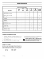
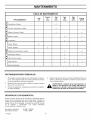
MAINTENANCE
MAINTENANCE
Tiresl
FIRST
2
HOURS
EACH
USE
PROCEDURE
I
"
Check
TABLE
I
EVERY
25
HOURS
I
"
•
_
EVERY
50
HOURS
I
"
EVERY
100
HOURS
BEFORE
STORAGE
''
•
•
M
O
Blade,
Inspect
W
Battery,
Check
and Sharpen
V
and Charge
V
E
R
Lubrication
E
N
Oil, Change
,,/
Cooling
System,
Muffler,
Check
I
'
Clean
I
I
I
_
'
_
G
I
N
_/
I
Air Filter, Clean
I
I
I
I
I
I
I
_
_/
I
I
I
I
E
Spark
Plug,
Check
Spark
Plug,
Replace
GENERAL
1.
warranty
2.
Check
_
responsibility
is to maintain
the life of the product
this product.
and is also necessary
4.
This will
to maintain
coverage.
the spark plug, drive brake,
lubricate
Check
CHECK
the fasteners.
,_
Make sure all fasteners
are tight.
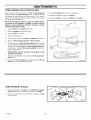
THE TIRES
Check the air pressure in the tires. Tires with too much air pressure
will cause the unit to ride rough. Also, the wrong air pressure will
keep the mower housing from cutting level. The correct air pressure
(PSI) is as follows. Semi-pneumatic front tires do not require air.
Front Tires
Rear Tires
F-040607L
"
Follow the Maintenance and the Service And Adjustment section to keep the unit in good operating condition.
WARNING:
the unit, and clean
the air filter once a year.
3.
_/
RECOMMENDATIONS
The owner's
extend
_/
22 PSI (1.5 BAR)
14 PSI (! BAR)
18
Before you make an inspection,
adjust-
ment, plug.
or repair
to the the
unit,wire
disconnect
wireplug
to the
spark
Remove
from the the
spark
to
prevent the engine from starting by accident.
MAINTENANCE
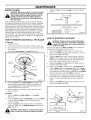
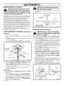
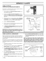
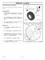
INSPECT
BLADE
WARNING:
disconnect
_lh
4.
Before you inspect or remove the blade,
the wire to the spark plug. If the blade
Tightenthe
pounds.
bladeto atorque of35foot
I
its an object,
stop the
Check When
the unit
damage.
The blade
has engine.
sharp edges.
you for
hold the blade, use gloves or cloth material to protect your hands.
I
Blade Adapter
If you keep the blade sharp and inspect the blade for damage,
the blade will cut better and be more safe to operate. Frequently
t_
s
check the blade for excessive
wear, cracks, or other damage.
Frequently
check the nut that holds the blade. Keep the nut tight.
If the blade hits an object, stop the engine. Disconnect
the wire to
the spark plug. See if the blade is bent or damaged.
Check the
blade adapter for damage.
Before you operate the unit, replace
damaged
parts with original equipment
parts. See a Sears
Service Center in your area. Every three years, have a qualified
service person inspect the blade or replace the old blade with an
original equipment
part.
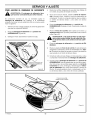
HOW TO REMOVE
nutthatholdsthe
BellevilleWashe" r
(Outside rim must be
against the blade.)
HOW TO SHARPEN
t
Blade
tJ
/
Washer
I_::_:lj
r-T-----n _"
Nut
I
Figure 13
THE BLADE
AND INSTALL THE BLADE
WARNING: Vibration
can be caused if the blade is
To Remove
1.
2.
Lift the side of the mower
3.
As you loosen
from
4.
notblade
correctly
if thecracks
blade can
is damaged.
A
that isbalanced
damagedorwith
break and
cause an accident.
Drain the fuel tank.
that has the muffler
the nut, use a piece
of wood
or spark
plug.
Keep a sharp edge on the blade. A blade that is not sharp will
cause the tips of the grass to become brown.
1. Sharpen the blade two times a year or every 25 hours.
2. Remove the blade according to the instructions in "How To
Remove And Install The Blade".
to keep the blade
rotating.
Remove
Hi-Lift
the nut, washers,
and blade
(Figure
12).
3.
Clean the blade with a brush, soap and water. Check the
blade. Look for cracks, nicks, or other damage. Replace a
badly worn or damaged blade with an original equipment
blade. See a Sears Service Center in your area.
4.
Sharpen the blade with a file (Figure 14). Make sure you
keep the original bevel angle.
Make sure the blade is balanced. Use a screwdriver and
hold the blade parallel to the ground (Figure 14). A blade
that is balanced will stay parallel to the ground. If the blade
is not balanced, the heavy end will rotate toward the ground,
Sharpen the heavy end until the blade is balanced.
A new blade will cut better than a badly worn blade. Every
three years, have a qualified service person inspect the
blade or replace the old blade with an original equipment
blade.
/
Edge Up
5.
,_
Mandrel
Adapter
6.
)_
Washer
Figure 12
5.
Check the blade and the blade adapter according to the
instructions for "Inspect Blade". Replace a badly worn or
damaged blade with an original equipment blade. See a
Sears Service Center in your area.
6.
Clean the bottom of the mower housing. Remove all the
grass and debris.
7.
To Install
1. Meunt the blade and blade adapter on the mandrel
(Figure 12).
2. Mount the blade so that the hi-lift edges are up. If the blade
is upside down, the blade will not cut correctly and can
cause an accident.
3.
Assemble the blade according to the instructions "How To
Remove And Install The Blade".
Screwdriv__
/
Fasten the blade with the original washers and nut. Make
sure the outside rim of the Belleville washer is against the
blade (Figure 13).
I
Fe
Blade is balanced
I when parallel to the ground, i
_
ARNING:
Always
keep
thecan
nut cause
tight that
holds the
blade.
A loose
nut or
blade
an accident.
F-040607L
Ground
19
Figure 14
MAINTENANCE
MAINTENANCE
FREE BATTERY
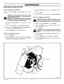
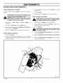
HOW TO REMOVE THE BATTERY
3.
Clean the terminals
brush.
To charge or clean the battery, remove the battery from the unit as
follows.
4.
Install the battery.
5.
To prevent corrosion, apply grease to the battery
WARNING: To prevent sparks, disconnect the black
battery cable from the negative (-) terminal before you
_
Disconnect the black cable from the negative
(Figure 15).
2.
terminals.
HOW TO CHARGE THE BATTERY
disconnect
the red
cable.
WARNING: The
battery
contains sulfuric acid which is
harmful to the skin, eyes and clothing. If the acid gets
on the body or clothing, wash with water.
1.
and the ends of the cables with a wire
smoke.
KeepWhen
the battery
away from
sparks.
WARNING:
you charge
the any
battery,
do The
not
fumes from the battery acid can cause an explosion.
_1=
(-) terminal
1.
Before you charge the battery,
Disconnect the red cable from the positive (+) terminal.
2.
To charge the battery, use a 12 volt battery charger. Charge at
a rate of 6 amperes for 1 hour.
3.
To disconnect the battery retainer from the battery tray, push
in on the lower end of the battery retainer.
3.
install the battery.
4.
Remove the battery from the right side of the unit.
,_
HOW TO CLEAN
THE
BATTERY
1.
Remove the battery.
2.
Wash the battery with a solution of one gallon of water and four
tablespoons of baking soda (sodium bicarbonate). Make sure
the solution does not get into the battery cells.
Battery
remove the battery.
the
positive To
(+)prevent
terminal sparks,
before fasten
you connect
black
WARNING:
the redthe
cable
to
cable.
4.
Fasten the red cable to the positive (+) terminal
teners as shown.
with the fas-
5.
Mount the battery
6.
Fasten the black cable to the negative (-) terminal with the fasteners as shown.
boot onto the positive (+) terminal.
A
Positive
(+)
Terminal
A
Black Cable
B
Red Cable
Battery Clamp
Figure 15
F-040607L
20
MAINTENANCE
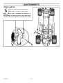
WHERE
_,,%_
TO LUBRICATE
Apply grease with a brush to the areas shown.
Lubricate the areas shown with engine oi!.
NOTE: Apply grease to the steering gear assembly,
CAUTION: If the unit is operated in dry areas that have sand,
use a dry graphite spray to lubricate the unit.
F-040607L
21
MAINTENANCE
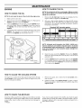
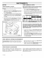
ENGINE
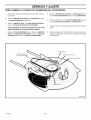
HOW TO CHANGE
HOW TO CHECK
NOTE: Do not drain the oil from a cold engine. Before you drain
the oil, let the engine run for several minutes. Make sure you do
not get oil on the belts.
THE OIL
NOTE: Do not check the level of the oil while the engine runs.
1.
Make sure the unit is level.
2.
Clean the area around the dipstick (Figure 17). Remove the
dipstick, Wipe the oil from the dipstick,
3.
Insert the dipstick into the oil fill tube. Turn the dipstick clockwise until it is tight. Remove the dipstick, Check the oil level on
the dipstick. The oil level must reach the FULL mark on the
dipstick.
4.
THE OIL
If necessary, add oil until the oil reaches the FULL mark on the
dipstick, The quantity of oil needed from ADD to FULL is
shown on the dipstick. Do not add too much oil.
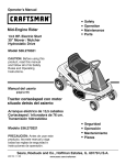
1.
Only use a high
classification
SF
according
to the
temperature
chart
quality detergent
oil rated with API service
or SG. Select the oil's SAE viscosity
grade
expected
operating
temperature
using the
below:
Required
SAE viscosity
grades
4
F
Air Screen
Remove the oil drain cap. Drain the oil completely from the
engine. Install and tighten the oil drain cap.
20
I
c 30
Dipstick
0
,
20
20
I
TEMPERATURE
1_
I
32
_
40
I
RANGE ANTICIPATED
60
1_
I
80
_0
I
100
3'0
I
40
BEFORE NEXT OIL CHANGE
NOTE: Although multi-viscosity
oils (5W30, 10W30, etc.)
improve starting in cold weather, they will result in increased
oil consumption when used above 320 F. Check the engine oil
level more frequently to avoid possible engine damage from
running low on oil.
Clean the area around the dipstick. Remove the dipstick.
Slowly pour approximately 48 ounces (3 pints) of oil into the oil
extension tube.
/
Oil Drain Cap
insert the dipstick into the oil extension tube. Turn the dipstick
in a clockwise direction until it is tight. Remove the dipstick.
Check the oil level on the dipstick. The oil level must reach the
FULL mark on the dipstick.
Engine Shroud
Figure 17
HOW TO CLEAN
THE COOLING
SYSTEM
The engine is air cooled. The air that cools the engine enters through
the air screen
on top of the engine. Clean the engine every 100
1.
Remove any grass, dirt or debris from the air screen with a
cloth or brush.
hours
2.
Inspect the edge of the engine shroud for grass or debris.
Remove any grass or debris visible at the bottom edge of the
engine shroud,
or every
year as follows.
HOW TO CHECK
Check
the muffler
THE MUFFLER
every 50 hours. Make sure the muffler
is correctly
mounted and is not loose. If the muffler is worn or burnt, replace with
a new muffler. A worn muffler is a fire hazard and can damage the
engine.
F-040607L
22
If you mount
a spark
arrester
to the muffler,
also check
the spark
arrester when you check the muffler. If the spark arrester is worn or
damaged,
replace it with a new spark arrester purchased
from a
Sears Service Center.
MAINTENANCE
HOW TO CLEAN
THE AIR FILTERS
Some engines have two filters, an outer foam filter around an inner
paper filter. Clean the air filters every 50 hours. If you operate in
dirty conditions, service more often.
11. Assemble the air filters with the nut.
12. install the cover. Fasten the cover with the knob.
NOTE: Never run the engine with the air filters removed. The air
filters will help protect the engine against wear. For the correct
replacement filter, see the parts list for the engine.
1.
Remove the knob from the cover (Figure 18).
2.
Remove the cover from the air cleaner.
3.
Remove the nut from the filters.
4.
Remove the air filters.
5.
Clean the inside of the base and the cover with a cloth.
6.
Remove the foam filter from the paper filter.
7.
If equipped, wash the foam filter in a detergent and water solution. To remove the water solution, tightly roll the foam filter in
a dry cloth. Remove the foam filter from the cloth. Completely
dry the foam filter.
j
Knob
C°ver/
Paper Filter
CAUTION: Do not wash the filters
solvents that will burn.
in gasoline
or other
8.
Evenly apply SAE 30W oil to the dry foam filter.
9.
To clean the paper filter, lightly tap the paper filter against a
hard flat surface.
10. If the paper filter is very dirty, replace the paper filter.
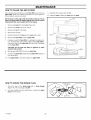
HOW TO CHECK
THE SPARK
PLUG
1.
Check the gap of the spark plug with a feeler
(Figure 19). The correct gap is 0.030".
2.
For easy starting and good performance,
plug every two years.
Feeler Gauge
0.030"
gauge
replace the spark
Spark Plug
F-040607L
23
Figure 19
SERVICE AND ADJUSTMENT
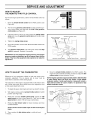
HOW TO ADJUST
THE REMOTE THROTTLE
CHOKE
CONTROL
For the best engine performance, set the remote throttle control as
follows.
1.
Move the remote
Figure
throttle
control
to the FAST
position
(see
20).
2.
The hole in the governor control lever (located just behind governor control plate) must align with the hole in the governor
control plate (see Figure 21).
3.
If the two holes
screw
FAST
Remote Throttle
Control
do not line up, then
and move the governor
loosen
control
the casing
SLOW
Figure 20
clamp
rack until the two holes
Hole In Governor
Control Plate
are aligned.
4.
Tighten the casing clamp screw.
5.
Check
the operation
of the throttle.
Move the _rottle
Governor Control Lever
Stop
control to Me
STOP position.
6.
The governor control lever must make good contact with stop
switch (if equipped). Readjust if necessary.
IMPORTANT: Do not change the engine governor. If the engine
governor needs an adjustment, go to the nearest Sears Service
Center. They have the equipment and experience to make the
adjustment.
HOW TO ADJUST
Governor Control Rack
THE CARBURETOR
6.
Move the remote
throttle
Casing Clamp Screw
control
to the FAST
Figure 21
position.
The
engine should accelerate
smoothly. If it does not, adjust the idle
mixture
valve counterclockwise
1/8 turn.
Differences
in fuel, temperature,
carburetor
adjustment.
The
assembled
to carburetor
before
altitude
air
or load may require
cleaner
starting
and
its
cover
minor
must
NOTE: Engines operated at approximately 3000 to 5000 feet (900
to 1500 meters) above sea level may require a high altitude
carburetor nozzle. If erratic performance is observed, contact a
Sears Service Center for cost to install or to purchase a high
altitude carburetor nozzle.
be
engine.
The carburetor on this engine is equipped with an idle mixture valve
with a limiter (see inset), which allows some minor adjustment,
and
an idle speed
adjustment
1.
To adjust
idle speed, start engine
2.
With engine running, put the remote throttle
position (see Figure 20).
3.
Rotate the carburetor throttle control lever against the idle
speed screw and hold it (see Figure 22). Then, turn the idle
speed screw to obtain 1750 rpm (use a tachometer).
4.
Rotate
the
idle
screw.
mixture
valve
and warm up about 5 minutes.
full travel
control in SLOW
clockwise
and
Idle Speed
Screw
then
counterclockwise.
NOTE: DO NOT remove limiter caps. DO NOT force beyond
limits.
Figure 22
5. Then, position idle idle mixture valve in middle of travel.
F-040607L
24
SERVICE AND ADJUSTMENT
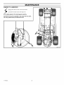
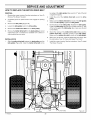
HOW TO LEVEL THE MOWER
If the mower housing
wi!! look better.
is level, the blade will cut easier
WARNING:
,_
HOUSING
and the lawn
Before you make an inspection,
Level Adjustm{
Position
adjust-
Lift Lever
ment, or repair to the unit, disconnect the wire to the
spark plug. Remove the spark plug wire to prevent
the engine from starting by accident.
1.
Make sure the unit is on a hard flat surface.
2,
Check
the air pressure
rect, the mower
are inflated
in the tires.
housing
If the air pressure
will not cut level.
\
Cover
Cutting Height
Positions
is incor-
Rear Adjuster Knob
Make sure the tires
Figure 23
to: Front Tires 22 PSi (1.5 BAR), Rear Tires 14 PSI.
(! BAR).
3.
Open the cover
(see Figure
23).
Front
Adjuster Knobs
4.
Move the lift lever
Figure
5,
to the LEVEL
ADJUSTMENT
position
(see
23).
Loosen the front and rear adjuster knobs (see Figure 23 and
Figure 24). Make sure both sides of the mower housing are setting on a flat surface. Also, make sure the lift links and adjuster
plates are loose and can easily move up or down.
Figure 24
6,
Tighten the front and rear adjuster knobs. Make sure the adjuster knobs are tight. If necessary, use a wrench to tighten the
adjuster knobs. For plastic adjuster knobs, tighten to a
torque of 7 foot pounds (9,5 N-m). For metal adjuster knobs,
tighten to a torque of 10 foot pounds (!3,5 N-m).
7.
Raise
the lift
a CUTTING
lever from
HEIGHT
the LEVEL
position
ADJUSTMENT
(Figure
position
to
25).
Cover
8.
9.
Close the cover.
Mow for a short distance.
the above
If the height of cut is not level,
repeat
Cutting Height Positions
steps.
CAUTION:
Do not operate with the mower housing in the
LEVEL ADJUSTMENT position. If you operate in the LEVEL
ADJUSTMENT position, the mower housing and blades can be
damaged.
F-040607L
Figure 25
25
SERVICE AND ADJUSTMENT
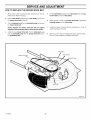
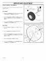
HOW TO ADJUST THE ATTACHMENT CLUTCH
_
4.
ARNING:
prevent
an injury, the attachment
clutch
must To
operate
correctly.
If the quality of cut has not improved, replace the mower drive
belt. See "How To Replace The Mower Drive Belt". If replacing
the belt does not correct the problem, take the unit to a Sears
or other qualified service center.
In normal usage, the attachment
clutch will not require an
adjustment. However, if the cutting performance decreases or the
quality of cut is poor, make the following changes.
1.
When you mow, make sure the throttle control in in the FAST
position.
2.
Move
(Figure
3.
the attachment
clutch
to the
DISENGAGE
Check the blade(s). Keep a sharp edge on the blade(s). A blade
that is not sharp will cause the tips of the grass to become
brown.
Move the attachment clutch to the DISENGAGE position,
Stop the engine. Disconnect the wire from the spark plug.
position
7.
26).
Stop the engine. Disconnect the wire from the spark plug.
_
8.
Check the operation of the blade brake, Rotate the pulley with
your hand. Make sure the brake pad is pressed tightly against
the pulley (Figure 27).
against
the pulley,
take thepad
unitdoes
to a Sears
or other
quARNING:
If the brake
not press
tightly
alified service center.
Move the attachment
clutch to the ENGAGE position.
Check the pad for the blade brake, If the pad is excessively
worn or damaged, replace the brake pad assemblies. Correct
replacement parts and assistance are available from a Sears
service center.
10. Attach the wire to the spark plug. Mow for a short distance and
again check the operation of the attachment clutch.
11.
Attachment Clutch
Engage Position
Figure 26
When you move the attachment clutch to the DISENGAGE
position, all movement will stop within five seconds. If there is
movement of the belt or the blades continue to rotate, engage
and disengage the attachment clutch five times to remove
any excess rubber from a new mower drive belt, If you need
assistance, take the unit to a Sears or other qualified service
center.
Blade Brake
(Pad Against Pulley)
Figure 27
F-O40607L
26
SERVICE AND ADJUSTMENT
HOW TO REMOVE
1.
2.
THE MOWER
HOUSING
HOW TO INSTALL
Move the attachment clutch to the DISENGAGE position.
Move the lift lever to the level adjustment position (Figure 28).
1.
2.
NOTE: Make sure the lift lever
is locked
in the LEVEL
ADJUSTMENT position.
3.
Remove the hair pins and the
washers from the rear suspension arms (Figure 29). See illustrations "C" and "D".
Level Adjustment
Remove the hair pins and washPosition
Figure 28
ers from the suspension
links.
See illustrations "A" and "B".
Disconnect the extension spring from the blade control rod,
See illustration "E".
4.
6.
Disconnect the front
illustration "F".
8.
7.
Remove the mower drive belt from the stack
illustration "G".
8.
9.
Pull the mower housing away from the right side of the unit.
To operate without the mower housing, move the lift lever to the
TOP position.
3.
4.
5.
hanger
from the frame support.
5.
6.
THE MOWER
HOUSING
Push the mower housing under the right side of the unit.
Put the mower drive belt around the stack pulley. Make sure
the %/" side of the mower drive belt is against the stack pulley.
Also, make sure the mower drive belt is not twisted.
Attach the front hanger to the frame support with the hanger
rod. Fasten with the fasteners as shown. See illustration "F".
Make sure the mower drive belt is between the stack pulley
and the two belt guides. See illustration "G".
Attach the suspension links to the lifter assembly. Fasten
with the washers and hair pins. See illustrations "A" and "B'.
Attach the rear suspension arms to the suspension brackets.
Fasten with the washers and hair pins. See illustrations "C" and
_D _.
7.
See
Attach the extension
illustration "E".
spring to the blade control rod. See
Move the attachment clutch to the ENGAGE position. Make
sure the mower drive belt is inside all the belt guides and is
also below the spacer tube.
9. Make sure the mower housing is level. See the instructions on
"How To Level The Mower Housing".
10. Check the operation of the attachment clutch. See the instructions on "How To Adjust The Attachment Clutch".
pulley. See
Lift Lever
Attachment
Clutch
_acer Tube
BeltGuide
f::l] I
G
D'
Adjuster
Arm
Lifter
Assembly
Stack Pulley
,j/
Suspension
Link
Adjuster
Arm
Mower
Drive Belt
Hanger Rod
Front Hanger
Extension
Suspension
Link
Spring
Figure 29
F-040607L
27
SERVICE AND ADJUSTMENT
HOW TO REPLACE
THE MOTION
DRIVE BELT
REMOVAL
1.
2.
top pulley of the stack pulley. Make sure the "V" side of the belt
is against the pulley.
Remove the mower housing. See the instructions on "How To
Remove The Mower Housing".
2.
Remove the idler pulley (Figure 30).
4.
Loosen the belt guides next to the drive pulley.
5.
Remove the motion drive belt from the drive pulley.
6.
Remove the motion drive belt from the stack pulley. A correct
replacement part or assistance is available from a Sears or
other qualified service center.
belt around the drive
3.
Make sure the motion drive belt is inside of the belt guides
next to the drive pulley. Tighten the belt guides.
4.
Put the belt around the idler pulley. Assemble the idler pulley.
Fasten the idler pulley with the hex nut. Make sure the "V" side
of the belt is against the idler pulley. Also, make sure the belt
is not twisted.
5.
Check the routing of the motion drive belt. Make sure the
motion drive belt is installed correctly on the idler pulley.
Make sure the motion drive belt is inside all the belt guides.
6.
Before you use the unit, check the adjustment of the clutch. See
the instructions "How To Check And Adjust The Clutch".
7.
Install the mower housing. See the instructions "How To Install
The Mower Housing".
INSTALLATION
1.
drive
pulley.
Completely push the pedal forward and engage the parking
brake.
3.
Install the end of the motion
Slide the motion drive belt between the stack pulley and the
belt guides (Figure 30). Install the motion drive belt on the
Belt Guide
Idler Pulley
Drive Pulley
Belt Guide
F-040607L
28
Figure 30
SERVICE AND ADJUSTMENT
HOW TO REPLACE
1.
2.
3.
THE MOWER
DRIVE BELT
on "How To
5.
Pull the belt retainer away from the idler pulley. Put the mower drive belt around the idler pulley.
Pull the belt retainer away from the idler pulley and remove
the mower drive belt (Figure 31).
6.
Make sure the "V" side of the mower drive belt is against the
jackshaft pulley and the idler pulley.
7.
Install
the mower
housing.
Install
The Mower
Housing".
Remove
the mower
Remove
The Mower
housing.
See the instructions
Housing".
Pull the brake pad away from the jackshaft pulley and remove
the mower drive belt.
NOTE: Replace the mower drive belt with an original
equipment belt purchased from a Sears Service Center.
4.
Install the new mower drive belt. Pull the brake pad away
from the jackshaft pulley. Put the mower drive belt around
the jackshaft pulley.
8.
Before
See the
instructions
you mow, check the attachment
tions on "How To Adjust
The Attachment
clutch.
on "How
See the instruc-
Clutch".
Idler Pulley
Belt Retainer
Mower Drive Belt
Jackshaft Pulley
Figure 31
F-040607L
29
To
SERVICE AND ADJUSTMENT
HOW TO INSTALL THE WHEELS
Cotter Pin
If the wheels must
installed as follows.
be removed
for service,
make
sure
they
are
Hub Cap
\
Front Wheel
1.
Make sure the valve
the front
wheel
etem
is to the outside
on the 8pindle
(See
Figure
of the tractor.
Slide
32).
Spindle
2.
Fasten the front wheel with washer and cotter pin. Bend the
ends of the cotter pin apart to keep the front wheel on the
spindle.
Valve Stem
3.
If your model has hub caps, install the hub cape. Make sure
the washers hold the hub caps in place.
Figure 32
Rear Wheel
Rear Wheel
1.
Front Wheel
Install
the washers
and
spacer
onto
the
axle
as shown
Figure
33.
2.
Mount
the square
3.
Make sure the valve etem is to the outside of the tractor, Align
the slot in the rear wheel with the square key. Slide the rear
wheel on the axle.
_,
Square Key
Key Slot
in
Washer
key in the key slot (See Figure
33).
4.
Fasten the rear wheel with washer
5.
If your model has hub caps, install the hub cape. Make sure
the washers hold the hub caps in place.
I
Spacer
Hub Oap
Axle
/
!
and e-ring.
E-Ring
F-040607L
Valve Stem
30
Figure 33
SERVICE AND ADJUSTMENT
HOW TO REPLACE
THE FUSE
If the fuse is blown, the engine
is next to the battery. Remove
automotive
fuse (Figure
THE ENGINE
will not start. The location of the fuse
the fuse and replace with a 15 amp.
34).
15 amp
1.
Clean
the dirt and grass from the engine.
2.
Change
3.
Check the air screen.
Cooling System".
See the instructions,
"How To Clean The
4.
Check the spark plug. See the instructions,
Spark Plug".
"How To Check The
the oil. See the instructions,
"How To Change
The Oil".
THE FUEL SYSTEM
Figure 34
HOW TO CLEAN
THE MOWER
stop the engine and disconnect
WARNING:
Before you clean
plug.
_b
Grass
and other
belt from
frequently
debris
around
on top of the mower
the pulleys
and other
1.
Move the lever for the attachment
tion.
2.
Clean the top of the mower
3.
Move the lever for the attachment
It is important to prevent gum deposits
system parts such as the carburetor,
the wire to the spark
the mower
housing,
housing
moving
during
operation,
grass and
fuel system
parts.
storage
posi-
Again
5.
After
clean
the top of the mower
to the DISENGAGE
FRONT WHEEL
The alignment
of the front wheels
STORAGE
GENERAL
the belts.
has changed,
take the unit to your
the unit for storage
as follows.
If the belts are damaged
or worn, replace
with
housing.
THE UNIT
See
To Lubricate"
"Where
(called
gasohol
or using
in storage.
the fuel system
Follow
should
these
be emptied
before
instructions:
See
"How
To Clean
do the following:
Start the engine.
2.
Run the engine until the fuel tank and the carburetor
fue! and the engine stops.
3.
Do not leave fuel in the fuel tank or the carburetor.
the function
After storage,
are out of
The fuel can
of the fuel system.
make sure you use fresh
fuel.
THE BATTERY
The Mower
1.
Remove
2.
Clean
3.
Charge
the battery.
the battery
terminals
the battery.
See the
of any deposits.
instructions
on "How
To Charge
The Battery".
4.
instructions
in the
Store
the battery
in a coo!, dry place.
Maintenance
section.
F-040607L
fuels
1.
4.
HOUSING
LUBRICATE
the
while
of 30 days or longer.
damage
belts from the factory. See the belt replacement
in the Service And Adjustment
section.
Clean the mower
Housing".
of an engine
If you do not use a stabilizer,
If the steering
Make sure all nuts, bolts and screws are tight. Inspect moving
parts for damage,
breakage
and wear. Replace if necessary.
MOWER
1.
cannot be adjusted.
INSPECTION
replacement
instructions
2.
housing.
(over 30 days)
At the end of each year, prepare
Inspect
of the mower
blended
ALIGNMENT
is damaged
and the alignment
nearest Sears Service Center.
1.
housing.
you cut the grass, clean the bottom
alcohol
NOTE: Fuel stabilizer
(like STA-BIL)
is an acceptable
alternative in reducing the formation of fuel gum in the fuel tank
and the gasoline storage container. Always follow the mix ratio
located on the container of stabilizer. Run the engine at least 10
minutes after adding the stabilizer to allow the stabilizer to
reach the carburetor. Do not drain the fuel tank and carburetor
if stabilizer is used.
housing.
position.
4.
Also,
To avoid engine problems,
clutch to the ENGAGE
clutch
storage.
from forming in essential fuel
fuel filter, fuel hose or tank
ethanol or methanol) can attract moisture which leads to separation
and formation
of acids during storage. Acidic gas can damage the
can keep the
working
correctly.
For safety and correct
clean the top of the mower housing. Remove
debris from
ing or near aDo
fire.notDodrain
not the
smoke
because
the a fumes
WARNING:
gasoline
inside
buildfrom the fuel can cause an explosion.
HOUSING
NOTE: After a long time in storage, charge the battery.
31
TROUBLESHOOTING
CHART
PROBLEM:
The engine will not start.
1. Follow the steps, "How To Start The Engine" in this book.
2.
Check the oil.
3.
Adjust the carburetor.
2.
Electric-Start
cables.
4.
Replace the fuel filter.
3.
Drain the fuel tank. Clean the fuel line. Replace the fuel filter.
PROBLEM:
4.
Remove the spark plug(s). Move the throttle to the SLOW position. Turn the ignition key to the ON position. Try to start the engine several times, install the spark plug.
1.
Replace the blade.
2.
Check for loose engine bolts.
3.
Decrease the air pressure in the tires.
Replace the spark plug.
Adjust the carburetor.
4.
Adjust the carburetor.
5.
Check for a damaged
damaged parts.
5.
6.
Models: Clean the battery terminals. Tighten the
Excessive
vibration.
belt or damaged pulley. Replace the
PROBLEM:
The engine will not turn over.
1. Follow the steps, "How To Start The Engine" in this book.
PROBLEM:
2.
Electric-Start Models: Check the level of the acid in the battery.
If needed, add water. Charge the battery.
1.
Stop the engine.
2.
Raise
3.
Replace the fuse.
3.
Replace
4.
Check the wiring harness for damage or a loose connection.
Repair the damaged wire.
4.
Move the shift lever to a slower
5.
Move the throttle
6.
Replace
5.
Electric-Start Models: replace the solenoid. Recoi!-Start Models: replace the module.
PROBLEM: The engine is difficult to start.
1.
Adjust
2.
Replace
the spark
3.
Replace
the fuel filter.
plug.
PROBLEM: The engine does not run smooth or has a
loss of power,
Check
2.
Clean the air filter.
3.
Clean the air screen.
4.
Replace
5.
The engine
6.
Adjust
7.
Replace
too hard.
the fuel filter.
The engine does
not run smooth at fast
speed.
the spark
the height of cut.
or sharpen
the blade(s).
control
the spring
for the blade
Replace the mower drive belt.
Adjust the clutch.
3.
Replace the motion drive belt.
3.
Clean the air filter.
PROBLEM:
The unit moves
clutch is engaged.
1. Adjust the clutch.
4.
Replace
2.
Check
Repair
plug.
2.
Replace
1.
control.
the fuel filter.
the wiring harness
the damaged wire.
stops when the blades
for damage
or a loose
are
Mow up and down
slopes.
Never
mow across
connection.
a slope.
Replace
2.
Clean the air filter,
the spark
3.
Adjust
the carburetor.
4.
Adjust
the throttle
5.
Drain the fuel tank.
plug.
the fuel filter.
PROBLEM: A hot engine causes a decrease in power.
1.
the
pedal is released,
belt
Replace the motion drive belt.
1.
Temporary belt noise does not change the operation of the unit.
If belt noise is continuous, check the routing of the belt. Make
sure the belt is inside all belt guides.
2.
If the noise is continuous,
2.
Clean the air screen.
F-040607L
when
adjust the clutch.
PROBLEM:
The transaxle
is difficult
to shift between
gears with the engine running and the clutch depressed.
1. Check the clutch adjustment to make sure the belt stops when
the clutch pedal is depressed with the transaxle in (N) neutral.
control.
Clean the fuel line. Replace
or stops
PROBLEM:
The rear wheels spin over uneven terrain.
1. Check the front axle. If the front axle does not freely pivot, loosen the axle bolt(s).
PROBLEM: The engine will not idle.
1.
slower
PROBLEM:
When the clutch/brake
noise can be heard.
PROBLEM: On slopes, the engine stops,
1.
not cut level.
Check the front axle. If the front axle does not freely pivot, loosen the axle bolt(s).
Adjust
The engine
idler.
Adjust the level of the mower housing.
2.
PROBLEM:
engaged,
position.
3.
1.
the throttle
speed.
to the FAST
PROBLEM:
The unit will not move when the clutch is
engaged.
1. Check the motion drive belt. Make sure the belt is installed
correctly.
Use a lower gear.
the carburetor.
PROBLEM:
correctly.
housing.
2.
2.
plug.
is working
the mower
PROBLEM:
The mower blades will not rotate.
1. Check the mower drive belt. Make sure the belt is installed correctly.
the oil.
the spark
does not discharge
Clean
PROBLEM:
The mower housing does
1. Check the air pressure in the tires.
the carburetor.
1.
The grass
32
Check the belt guides around the transaxle drive pulley. Make
sure the belt guides do not touch the pulley.
SEARS,
Federal and California
CALIFORNIA
& US EPA EMISSION
STATEMENT
CONTROL
ROEBUCK
WARRANTY
The U. S. Environmental Protection Agency ("EPA"), the California Air Resources Board ('CARB") and Sears, Roebuck and Co. are pleased to explain
the Federal and California Emission Control Systems Warranty on your new
small off-road engine. In California, new 1995 and later small off-road engines must be designed, built and equipped to meet the State's stringent
anti-smog standards. In other states, new 1997 and later model year engines must be designed, built and equipped, at the time of sale, to meet the
U.S. EPA regulations for small non-road engines. Sears, Roebuck and Co.
will warrant the emission control system on your small off-road engine for the
periods of time listed below, provided there has been no abuse, neglect, unapproved modification, or improper maintenance of your small off-road engine.
Your emission control system may include parts such as the carburetor, ignition system and exhaust system. Also included may be the compression release system and other emission-related assemblies.
Where a warrantable condition exists, Sears, Roebuck and Co. will repair
your small off-road engine at no cost to you for diagnosis, parts and labor.
MANUFACTURER'S
EMISSION
CONTROL
WARRANTY
COVERAGE
SYSTEM
Emission control systems on 1995 and later model year California small oftroad engines are warranted for two years as hereinafter noted. In other
states, 1997 and later model year engines are also warranted for two years.
If, during such warranty period, any emission-related part on your engine is
defective in materials or workmanship, the part will be repaired or replaced
by Sears, Roebuck and Co.
OWNER'S
WARRANTY
RESPONSIBILITIES
As the small off-road engine owner, you are responsible for
of the required maintenance listed in your Owner's Manual,
buck and Co. will not deny warranty solely due to the lack
your failure to provide written evidence of the performance
maintenance.
the performance
but Sears, Roeof receipts or for
of all scheduled
As the small off-road engine owner, you should, however, be aware that
Sears, Roebuck and Co. may deny you warranty coverage if your small offroad engine or a part thereof has failed due to abuse, neglect, improper maintenance or unapproved modifications.
You are responsible for presenting your small off-road engine to a Sears,
Roebuck and Co. Authorized Service Outlet as soon as a problem exists.
The warranty repairs should be completed in a reasonable amount of time,
not to exceed 30 days.
Warranty service can be arranged by contacting either a Sears, Roebuck
and Co. Authorized Service Outlet, or by contacting Sears, Roebuck and Co.
at 1-800-473-7247.
IMPORTANT
AND CO.
Emission Control Systems
Small Off-Road Engines
NOTE
This warranty statement explains your rights and obligations under the Emission Control System Warranty ("ECS Warranty") which is provided to you by
Sears, Roebuck and Co. pursuant to California law. See also the Sears, Roebuck and Co. Limited Warranties for Sears, Roebuck and Co. which is enclosed therewith on a separate sheet and also is provided to you by Sears,
Roebuck and Co. The ECS Warranty applies only to the emission control
system of your new engine. To the extent that there is any conflict in terms
between the ECS Warranty and the Sears, Roebuck and Co. Warranty, the
ECS Warranty shall apply except in any circumstances in which the Sears,
Roebuck and Co. Warranty may provide a longer warranty period. Both the
ECS Warranty and the Sears, Roebuck and Co. Warranty describe important
rights and obligations with respect to your new engine.
Warranty service can only be performed by a Sears, Roebuck and Co. Authorized Service Outlet. At the time of requesting warranty service, evidence
F-040607L
33
Limited Warranty
must be presented of the date of sale to the original purchaser. The purchaser shall pay any charges for making service calls and/or for transporting the
products to and from the place where the inspection and/or warranty work
is performed. The purchaser shall be responsible for any damage or loss incurred in connection with the transportation of any engine or any part(s)
thereof submitted for inspection and/or warranty work.
If you have any questions regarding your warranty rights and responsibilities,
you should contact Sears, Roebuck and Co. at 1-800-473-7247.
EMISSION CONTROL SYSTEM WARRANTY
Emission Control System Warranty ("ECS Warranty") for 1995 and later
model year California small off-road engines (for other states, 1997 and later
model year engines):
A. APPLICABILITY:
This warranty shall apply to 1995 and later model year
California small off-road engines (for other states, 1997 and later model year
engines). The ECS Warranty Period shall begin on the date the new engine
or equipment is delivered to its original, end-use purchaser, and shall continue for 24 consecutive months thereafter.
B. GENERAL EMISSIONS WARRANTY COVERAGE: Sears, Roebuck
and Co. warrants to the original, end-use purchaser of the new engine or
equipment and to each subsequent purchaser that each of its small off-road
engines is:
1. Designed, built and equipped so as to conform with all applicable regulations adopted by the Air Resources Board pursuant to its authority in Chapters 1 and 2, Part 5, Division 26 of the Health and Safety Code, and
2. Free from defects in materials and workmanship which, at any time during
the ECS Warranty Period, will cause a warranted emissions-related
part to
fail to be identical in all material respects to the part as described in the engine manufacturer's application for certification.
C. The ECS Warranty only pertains to emissions-related
gine, as follows:
parts on your en-
1. Any warranted, emissions-related
parts which are not scheduled for replacement as required maintenance in the Owner's Manual shall be warranted for the ECS Warranty Period. If any such part fails during the ECS
Warranty Period, it shall be repaired or replaced by Sears, Roebuck and Co.
according to Subsection 4 below. Any such part repaired or replaced under
the ECS Warranty shall be warranted for any remainder of the ECS Warranty
Period.
2. Any warranted, emissions-related part which is scheduled only for regular
inspection as specified in the Owner's Manual shall be warranted for the ECS
Warranty Period. A statement in such written instructions to the effect of "repair or replace as necessary", shall not reduce the ECS Warranty Period.
Any such part repaired or replaced under the ECS Warranty shall be warranted for the remainder of the ECS Warranty Period.
3. Any warranted, emissions-related
part which is scheduled for replacement as required maintenance in the Owner's Manual, shall be warranted for
the period of time prior to the first scheduled replacement point for that part.
If the part fails prior to the first scheduled replacement, the part shall be repaired or replaced by Sears, Roebuck and Co. according to Subsection 4 below. Any such emissions-related part repaired or replaced under the ECS
Warranty, shall be warranted for the remainder of the ECS Warranty Period
prior to the first scheduled replacement point for such emissions-related
part.
4. Repair or replacement of any warranted, emissions-related
part under
this ECS Warranty shall be performed at no charge to the owner at a Sears,
Roebuck and Co. Authorized Service Outlet.
5. The owner shall not be charged for diagnostic labor which leads to the determination that a part covered by the ECS Warranty is in fact defective, provided that such diagnostic work is performed at a Sears, Roebuck and Co.
Authorized Service Outlet.
6. Sears, Roebuck and Co. shall be liable for damages to other original engine components or approved modifications proximately caused by a failure
under warranty of an emission-related part covered by the ECS Warranty.
7.Throughout
theECSWarranty
Period,
Sears,
Roebuck
andCo.shall EMISSION-RELATED
PARTS INCLUDE
THE
maintain
asupply
ofwarranted
emission-related
parts
sufficient
tomeet
the 1. Carburetor Assembly and its Internal Components
expected
demand
forsuch
emission-related
parts.
a) Fuel filter
8.AnySears,
Roebuck
andCo.authorized
andapproved
emission-related
Carburetor gaskets
replacement
partmaybeused
intheperformance
ofanyECSWarranty b)
maintenance
orrepair
and
willbeprovided
without
charge
totheowner.
Such c) Intake pipe
useshall
notreduce
Sears,
Roebuck
andCo.ECS
Warranty
obligations. 2. Air Cleaner Assembly
9.Unapproved
add-on
ormodified
parts
maynotbeused
tomodify
orrepair a) Air filter element
aSears,
Roebuck
andCo.engine.
Such
usevoids
thisECS
Warranty
and 3. Ignition System, including:
shallbesufficient
grounds
fordisallowing
anECS
Warranty
claim.
Sears, a) Spark plug
Roebuck
andCo.shallnotbeliable
hereunder
forfailures
ofanywarrantedb) Ignition module
parts
ofaSears,
Roebuck
andCo.engine
caused
bytheuseofsuch
anun- c) Flywheel assembly
approved
add-on
ormodified
part.
FOLLOWING:
4. Catalytic Muffler (if so equipped)
a) Muffler gasket (if so equipped)
b) Exhaust manifold (if so equipped)
5. Crankcase Breather Assembly and its
Components
a) Breather connection tube
10/22/99 EPA/CARB
Sears, Roebuck and Co., Hoffman Estates, IL 60179 U.S.A.
F-040607L
34
SLOPE GUID
4_
......... .l_. D_'_,__
1
.""--_._._._'S
I
"" 'i ' "
Fold this page along dotted line indicated below. Hold page before you so that its left
edge is vertically parallel to a tree trunk or other upright structure.
Sight across the
fold in the direction of the hill or slope you want to measure.
Compare the angle of the
fold with the slope of the hill.
".......
i.........................
.
"......
ALONo
......
_i _.
.
eolbooe
a
meleee
IQ='ee°eOeOoem_emo
I
Q
Operate a walk-behind mower
across the face of slopes,
never up or down slopes.
LO
03
I
I
CA
10 DEGREES
,.
15 DEGREES
Operate a riding mower
up or down slopes, never
across the face of slopes.
On a riding mower to determine if a slope is safe to mow: (1) disengage the blade(s), (2) put the unit in reverse, and (3) try to back straight up the
slope. If you can back up the slope, it is generally safe to mow. However, if you do not feel safe, or you are not completely sure, use this guide to
determine the slope angle.
pull-behind To
or avoid
rear-mounted
do not
operate
unit on
slope
that than
is greater
than 10
WARNING:
possible attachment,
serious injury,
do not
mow the
a slope
thata is
greater
15 degrees.
If degrees.
the riding mower is used with a
_J
b.0
CO
o
.................................
_u'TAE'R_
fO'U_E'S_6P_
5U%'E
.................................
.q0
MODEL 536.270290
REPAIR PARTS
CHASSIS & HOOD
45
/
5
6
10
12
20
21
19
8
4
j"
16
16
\
\
24
/
22
/
16
15
29
26
/
30
32
43
27
19
\
28
20
4.2
r
/
13
46
40
37
39
F-O40607L
36
MODEL 536.270290
Key
No.
REPAIR PARTS
CHASSIS & HOOD
Key
No.
Part No.
Description
Seat
24
26x253
Screw
1401027E201
Hood
26
1401110
Rod, Hood Prop
3
017x47
Washer
27
1401282
Spring, Seat Deck
4
1001054
Bolt, Wing
28
1401297E701
Bracket, Prop Rod
5
002x53
Bolt, Carriage
29
26x201
Screw
6
1401036E701
Bracket, Hinge
30
15x116
Nut, NY-Lock
7
009x29
Bolt, Shoulder
31
1401248
Control, Throttle
8
009x56
Bolt, Shoulder
32
1401084
Cover, Detent (Black)
10
1401113
Rod, Battery
33
009x47
Bolt, Shoulder
11
015x84
Nut, Flange
36
1401145
Footmat, Left
12
1401025E701
Plate, Rear
37
1401144
Footmat, Right
13
26x249
Screw
39
1401298E701
Frame
14
1401050E701
Plate, Hitch
40
1401219E201
Deck, Seat
15
1401087
Cover, Black
41
094744
Bumper
16
26x263
Screw
42
15x116
Nut
17
1401076E701
Tray, Battery
43
0025x2
Screw
18
015x79
Nut, Flange
44
7601036
Kit, Foil Heat Shield
19
017x45
Washer
45
1401073
Trim, Left
20
0031x6
Pin, Cotter
46
1401072
Trim, Right
21
092317
Cap, Fuel Tank
47
0193xl
Fastener, Panel
22
1401240
Tank, Fuel
- -
F-040607L
Book, Instruction
23
06x111
Screw
Part No.
Description
1
690566
2
F-O40607L
37
MODEL 536.270290
REPAIR PARTS
STEERING
2
36
/
/
/
38
\
\
\
32
o
C.P
12
/
10
/
34
35
23
/
30
/
k
9
"_
/
17
\
\
J
14
29
\
\
21
F-O40607L
38
13
/
REPAIR PARTS
STEERING
MODEL 536.270290
Key
No.
*
Part No.
Description
1
095185
Wheel, Steering
2
711326
3
Key
No.
Part No.
Description
21
01x146
Bolt, Hex
Cap, Steering (Black)
22
011x23
E-Ring, Retainer
1401067
Console, High (Black)
23
030x35
Pin, Cotter
4
26x250
Screw
24
094131
Retainer, Spring
5
1401090
Bearing, Upper Steering
25
1401046E701
Rack, Steering
7
1401100
Shaft, Steering
26
17x201
Washer
8
1401055E701
Support, Steering
27
1401060E701
Bracket, Axle Front
9
26x249
Screw
28
17x157
Washer
10
009x67
Bolt, Shoulder
29
1401250E701
Axle & Spindle Assembly
11
1401098
Bearing, Lower Steering
30
1401059E701
Bracket, Support
12
1401102
Roller
31
15x118
Nut, Flange
13
1401058E701
Plate, Gear Mounting
32
1401143
Wheel, Front
14
1401123E701
Link, Drag
33
17x197
Washer
15
015x84
Nut, Flange
34
17xl 57
Washer
16
17x104
Washer
35
094618
Cap, Hub
17
015x88
Nut, Flange
36
0025x3
Bolt
18
01x111
Bolt, Hex
37
17x146
Washer
19
17xl 18
Washer
38
26x270
Screw
20
1401099
Gear, Pinion
When you order a tire, make sure to give the brand name of the tire so that the tread pattern on the tire will match,
F-040607L
39
MODEL 536.270290
REPAIR PARTS
MOTION DRIVE
lO
14
12
11
/
20
\
/
\,J
23
19
16
22
18
24
58
17
//_1
21
11
25
34
13
31
1
30 15_
_).
/-
32
\
33
\
\
\
I
'\
\
35
37
\
\
\
/
I
40
\
'\
\\\
43
36
45
11
s6.--q-,_
49
--"
10
57_!
\
74
52
15_
13/
j
13
64
\
51
\
69
50
15
65
66
\
70
F-O40607L
52
/
53
64
68
40
5O
j,
J
67
\
/
c_\i
15
/
53
51
MODEL 536.270290
Key
No.
1
*
Part No.
.....
Description
Engine, Briggs & Stratton
2
01x134
Bolt, Hex
3
1401207
4
REPAIR PARTS
MOTION DRIVE
Key
No.
37
Part No.
1401078
Description
Rod, Clutch
38
1401128E701
Clutch Arm Assembly
Shield Assembly, Heat
39
0011x7
Ring, Retainer
018x32
Lockwasher
40
1401077
Pulley, Drive
5
0025x2
Screw
41
002x53
Bolt, Carriage
6
1401251
Muffler
42
009x39
Bolt, Shoulder
7
091309
Gasket, Muffler
43
1401252
Pulley, Idler
8
165x75
Spring, Extension
44
37x110
Belt, Motion Drive
9
165xl 48
Spring, Extension
45
1401066
Pulley, Split Stack
10
015x88
Nut
46
019x35
Washer, Star
11
26x249
Screw
47
17xl 70
Washer
12
1401268E701
Bracket, Left Transaxle
48
01x140
Bolt, Hex
13
015x84
Nut, Flange
49
17xl 02
Washer
14
021544
Cover, Pedal
50
1401031 E701
Arm, Rear
15
0031x4
Pin, Cotter
51
1401039E701
Bracket, Rear Hanger
16
017x53
Washer
52
094067
Pin, Threaded Shoulder
17
030x20
Pin, Cotter
53
01 x155
Bolt, Hex
18
1401127E701
Pedal Assembly
54
01x120
Bolt
19
1401112
Rod, Parking Brake
55
1401051E701
Bracket, Torque Reactor
20
091079
Grip, Parking Brake Rod
56
06x105
Screw
21
1401298E701
Frame
57
017X38
Washer, Shift Yoke
22
092697
Grip, Shift Lever
58
1401260E701
Plate, Reinforcement
23
1401148 Z
Nut, Adjusting
59
1401093 Z
Yoke, Shift
24
1401122
Link, Shift
60
17x148
Washer
25
1401111
Lever, Shift
61
......
Transaxle, Peerless
26
1401032E701
Bracket, Lift Pivot
62
1401042E701
Bracket, Right Transaxle
27
165xl 47
Spring, Extension
64
17xl 60
Washer
28
009x39
Bolt, Shoulder
65
056534
Key, Square
29
1401043E701
Bracket, Pivot
66
1401103 Z
Spacer, RearWheel
30
1401104
Guide, Belt-Short
67
1401120
Wheel, Rear-15"
31
1401105
Guide, Belt -Long
68
094618
Cap, Hub
32
1401057E701
Plate, Belt Guide
69
0011x3
E-Ring
33
0025x7
Bolt
70
17xl 95
Washer
34
015x79
Nut, Flange
72
092378
Lock, Screw
35
1401059E701
Bracket, Support
73
015x43
Nut
36
094815
Nut, Adjusting
74
015x98
Nut
When you order a tire, make sure to give the brand name of the tire so that the tread pattern on the tire will match,
F-040607L
41
MODEL 536.270290
REPAIR PARTS
MOWER HOUSING SUSPENSION
2_
]
13
5
14
5
_
4
•
_
j
10
9
I
/
31
/
12
9
24
13
23
17
20
F-O40607L
42
30
MODEL 536.270290
Key
No.
Part No.
Description
1
092697
Grip, Lift Lever
2
1401117
3
REPAIR PARTS
MOWER HOUSING SUSPENSION
Key
No.
Part No.
Description
15
17x206
Washer
Lever, Lift
17
015x79
Nut, Flange
165xl 54
Spring, Extension
18
015x84
Nut, Flange
4
094137
Pad, Friction
19
1401147
Spring, Leaf
5
017x45
Washer
20
1401040E701
Hanger, Front
6
095004
Wingnut
21
1401116
Lever, PTO
7
1401033E701
Link, Lift
22
26x263
Screw
8
1401096
Tube, Spacer
23
094198
Grip, PTO
9
0031x4
Pin, Hair
24
1401199E701
Bracket, PTO
10
002x93
Bolt, Carriage
25
009x42
Bolt, Shoulder
11
1401030E701
Bracket, Front Hanger Pivot
26
165x157
Spring, Extension
12
1401118
Pin, Front Hanger
27
165x92
Spring, Extension
13
26x249
Screw
30
1401260E701
Plate, Reinforcement
14
1401129E701
Arm Assembly, Lifter
31
26x267
Screw
F-O40607L
43
MODEL 536.270290
REPAIR PARTS
MOWER HOUSING
7
3
9
4
63 /
8
©
5
12
30
\
32
31
29
13
34
24
14
7
I
I 26
6
27
35
8
/
J \
J
28
_9
29
36
\
9
!/
\
18
9
6
6_
\
15
_
39
64
8
\ \
10
16
22
21
43
12 _
50
45
47
42
52
\
/_/
52
53
54
/
45
62
51
56 /
/
55
/
57
58
F-O40607L
44
20
19
MODEL
Key
No.
REPAIR PARTS
MOWER HOUSING
536.270290
Key
No.
Part No.
Description
32
009x42
Bolt, Shoulder
34
030x20
Pin, Cotter
35
1401185E701
Arm Assembly, Brake
36
1401119
Link, Idler Arm
37
0025x7
Bolt
38
1401052E701
Bracket, Brake Mounting
Arm, Rear
39
1401094
Spacer, Jackshaft
015x79
Nut, Flange
40
1401259 Z
Plate, Idler Mounting
9
009x58
Bolt, Shoulder
42
019x45
Washer
10
1401033E701
Link, Lift
43
002x94
Bolt, Carraige
11
17xl 02
Wash er
45
002x53
Bolt, Carriage
12
0031x4
Pin, Hair
47
1401028E701
Housing, Blade
13
094067
Pin, Threaded Shoulder
48
1401106E701
Hinge, Mulching Cover
14
1401047E701
Bracket, Left Rear
49
015x88
Nut, Flange
15
1401296E701
Bracket, Right Rear
5O
028x76
Nut, Speed
16
1401038E701
Plate, Adjustment
51
014x86
Wingnut
17
094137
Pad, Friction
52
002x74
Bolt, Carriage
18
017x45
Washer
53
091767 Z
Rod, Chute Deflector
19
095004
Wingnut
54
028x23
Cap, Push
20
166x43
Spring, Left Torsion
55
1401080
Cover, Mulch
21
166x42
Spring, Right Torsion
56
094305
Mandrel Housing
22
1401095
Tube, Spacer
57
1001035
Adapter, Blade
23
1401037E701
Bracket, Deck
58
1401079E701
Blade
24
1401040E701
Hanger, Front
59
17xl 66
Washer, Cup
26
1401065
Shaft, Splined
60
17xl 65
Washer
27
1401258E701
Arm Assembly,
61
15xl 00
Nut, Blade Mount
28
009x39
Bolt, Shoulder
62
1401081
Deflector, Chute
29
017x47
Washer
63
017x91
Washer
30
165xl 57
Spring, Extension
64
001 x84
Bolt
31
166x46
Spring, Torsion
Part No.
Description
1
37x111
Belt, Blade Drive
2
1401092
Pulley, Input
3
15xl 40
Locknut
4
015x98
Nut, Flange
5
1401252
Pulley, Idler
6
015x84
Nut, Flange
7
1401031E701
8
F°040607L
Idler
45
MODEL 536.270290
REPAIR PARTS
ELECTRICAL
SYSTEM
_515AMP
FUSE
RED
/
RED
NO
|
IGNITIONSWITCH |
I OFFI M+G
I RUralB+L
ORANGE
IRUN21 .....
ISTARTI
SOLENOID
B+S
/',_,.__.,_z_
_
CLUTCH
BRAKE
I
I
SWITCH
DISENGAGED
(PEDAL U_
IGNIllON
SWITCH
VIEWED
FROM
SACK
m
SPARK
PLUG
SEAT SWITCH
YELLOW
®
BLACK
SEAT SWITCH
UNOCCUPIED
L
BLACK
S
m_
®
ORANGE
II
BED DC
OUTPUT
TEST
GRAPHIC
REPRESENTATION
OF IGNITION
SWITCH
PORT
STARTER
(SHOWN
IN
YELLOW
PTO SWITCH
DISENGAGED
PTO OFF
ORANGE
NO
F-040607L
YELLOW
ORANGE
46
OFF
POSITION)
MODEL 536.270290
Key
No.
3
REPAIR PARTS
ELECTRICAL SYSTEM
Part
No.
Description
250xl 15
Harness, Chassis Wire
1401149
Switch, Ignition
327349
Key, Ignition
1001575
Switch, Limit
302031
Fuse
407078
Holder, Fuse
094613
Solenoid
26x229
Screw, Mounting
15x116
Locknut
024x37
Cable, Battery Ground
Screw, Ground Cable
F-040607L
092739
Battery
002x82
Bolt, Carriage
014x79
Wingnut
094159
Switch, Seat Sensor
0025x2
Bolt, Carriage
15x116
Wingnut
024x24
Cable, Red B_ery
690604
Boot, Positive Terminal
47
MODEL 536.270290
Key
No.
--
F-040607L
REPAIR PARTS
DECALS
Part No.
Description
48x5212
Gas Gage (Dash -Left Side)
1
44x7197
DEKA (Battery)
1
44x7325
Warning (Seat Deck -Middle)
1
48x5208
1-5 Height Adjust (Seat Deck -Left Side)
1
48x746
NO STEP (Mower Deck - Left Side)
1
48x5211
Clutch / Brake ( Footrest -Left Side)
1
48x236
Cut Finger (Mower Deck -Right Side)
1
48x5491
Craftsman 13,5 (Hood -Right Side)
1
48x5492
Craftsman 13.5 (Hood -Left Side)
1
48x5490
Gear Select 5 speed
1
48x5214
Deck Level Position / ONLY (Seat Deck -Left Side)
1
48x5057
Warning Load Limit (Rear)
1
48x5213
Craftsman Logo (Seat Deck Front)
2
48x5209
Parking Brake Symbol (Console)
1
48x5210
Throttle Control (Console)
1
48x5205
Blade Engage / Disengage (Seat Deck -Right Side)
1
48x5215
Steering Wheel
1
48x5204
Starting Instructions
1
48x1019
13,5 HP I/C B&S (Engine)
1
(Location)
48
Qty.
NOTES
F-O40607L
49
MODEL 536.270290
ENGINE 28R707-1120-E1
11
I 1019
KIT-LABEL
I
11o_8
OWNER'S
MANUAL
I
307_
691 @_
718
13
IO_
383
24_
668
733
635
,_J
810 t
46
146
27 _
20
F-O40607L
50
MODEL 536.270290
RER
NO.
PART
NO.
1
496413
2
399265
3
_391086
4
494238
5
494240
7 O_271866
8
495735
ENGINE 28R707-1120-E1
RER
NO.
DESCRIPTION
PART
NO.
Cylinder Assembly
Kit-Bushing/Seal
(Magneto
Seal-Oil
Side)
(Magneto Side)
Sump-Engine
Head-Cylinder
Gasket-Cylinder
Head
Breather Assembly
Gasket-Breather
9
G_27803
10
691666
Screw
11
691328
(Breather Assembly)
Tube-Breather
12
_692226
27
28
494504
(.015" Thick, Standard)
.......
Note
.....
_692406
Gasket-Crank-
case
(.005" Thick)
_692405
Gasket-Crankcase
13
13A
690348
690904
33
262246
Head)
691681
(Cylinder
Screw
34
35
262247
691605
(Cylinder
Head)
36
691597
690946
693944
_291675
692125
Plug-Oil
Drain
Crankshaft
Seal-Oi!
(PTO Side)
Screw
(Engine
222698
Key- Flywheel
25
696397
Piston Assembly
(Standard)
.......
Note
696398
Piston
Piston
(.030" Oversize)
F-O40607L
40A
691939
494553
691968
45
691811
.....
46
697668
Assembly
146
691639
306
690459
696399 Piston Assembly
(.020" Oversize)
696403
690656
42
43
(.010" Oversize)
696400
40
Sump)
24
26
690356
32A
16
20
22
32
(.009" Thick)
Screw
15
Ring Set
(Standard)
Assembly
Note
.....
696404 Ring Set
(.010" Oversize)
696405 Ring Set
(.020" Oversize)
696406 Ring Set
(.030" Oversize)
Lock-Piston Pin
Pin-Piston
(Standard)
Note
.....
496320 Pin-Piston
29
Gasket-Crankcase
691299
498319
DESCRIPTION
(.005" Undersized)
Rod-Connecting
(Standard)
Note
.....
495490 Rod-Connecting
(.020" Undersized)
Screw
(Connecting Rod)
Screw
(Connecting Rod)
Valve-Exhaust
Valve-Intake
Spring-V alve
(Intake)
Spring-V alve
(Exhaust)
Retainer-V alve
(Intake)
Retainer-V alve
(Exhaust)
Keeper-V alve
Slinger-Governor/Oil
Tappet-V alve
Camshaft
Key-T iming
Shield-Cylinder
(Used Before Code Date
02112000).
Note
.....
696477 Shield-Cylinder
(Used After Code Date
02111900).
51
RER
NO.
PART
NO.
307
691003
308
491490
322
692198
322A
691681
337
802592
383
552
89838
491986
635
66538
668
690510
691
718
_692407
690959
733
691658
741
757
691284
691714
758
692423
759
691239
761
691096
810
691779
869
691802
870
691844
871
261961
1019
491252
1058
274787
DESCRIPTION
Screw
(Cylinder Shield)
Cover-Cylinder Head
(Used Before Code Date
02112000).
Note
.....
698476 Cover-Cylinder
Head
(Used After Code Date
02111900).
Screw
(Cylinder Head Cover)
Screw
(Cylinder Head Cover)
Spark Plug
Wrench-Spark Plug
Bushing-Governor
Crank
Boot-Spark Plug
Spacer
Seal-Governor Shaft
Pin-Locating
Screw
(Crankshaft Extension)
Gear-T iming
Link-Counterweight
Counterweight
Pin-Counterweight
Screw
(Counterweight)
Extension-Crankshaft
Seat-V alve
(Intake)
Seat-V alve
(Exhaust)
Bushing-Valve Guide
(Exhaust Valve)
Note
.....
231216 Bushing-Valve
Guide
(Intake Valve, Brass)
Kit-Labe!
Owners Manual
(Emission)
MODEL 536.270290
1251
ENGINE 28R707-1120-E1
1311
95_
987
231 _
_
692
_
/s I
634_I
54
1091_
276 _
950
106
108A _
634A
_
616
II
130A _
987@
j[
95_
939}
614Ii
J
404
222
265
267 _
188
209
216
202
562 _!;_
232 f
877
334
1119_
F-O40607L
52
851
MODEL 536.270290
RER
NO.
PART
NO.
DESCRIPTION
REE
NO.
PART
NO.
DESCRIPTION
RER
NO.
PART
NO.
334
691061
Screw
DESCRIPTION
50
691711
131
494885
Kit-Throttle
Shaft
51
e_,692284
Gasket-Intake
131A
494379
Kit-Throttle
Shaft
Gasket-Intake
133
494381
Float-Carburetor
404
691691
(Magneto
Washer
Armature)
51A _¢_272554
691098
Stud
137
141
e_,281165
495097
Gasket-Float
Bowl
Kit-Choke
Shaft
474
696459
(Governor
Alternator
Crank)
690953
(Carburetor)
Screw
691251
Nut
495931
(Manual Choke)
Kit-Choke
Shaft
505
141A
Lever'
691119
(Governor
Bolt
Control
562
(Governor
Pin-Cotter
Control
Lever'
691620
692012
Crank-Governor
53
54
Manifold-intake
ENGINE 28R707-1120-E1
(Intake
Manifold)
93
94
e690602
498030
Bushing-Throttle
Kit-idle
Mixture
142
697592
(Choke A Matic)
Nozzle-Carburetor
95
e691636
Screw
186
698174
Connector-Hose
614
691693
Screw
616
495800
(Throttle Valve)
Kit-idle
Speed
188
98
634
104
105
e690525
e231855
Pin-Float
Hinge
Valve-Float
Needle
202
691841
(Control Bracket)
Link-Mechanical
106
e690577
Seat-inlet
108
690464
Valve-Choke
209
216
690480
691840
Spring-Governor
Link-Choke
692
690572
Spring-Detent
692344
(Manual Choke)
Valve-Choke
222
227
694042
691374
Bracket-Control
Lever-Governor
851
877
493880
393456
231
e691636
125
698171
(Choke A Matic)
Carburetor
Terminal-Spark
Wire/ConnectorAlternator
950
691657
Screw
127
130
694524
690468
Plug-W elch
Valve-Throttle
232
691842
Spring-Governor
Clamp-Casing
Screw
495933
(Float Bowl)
Bowl-Float
Valve-Throttle
691024
690804
975
691750
265
267
108A
130A
Shaft
(Casing
F-040607L
o_,692255
333
492341
634A
Control
e690802
Screw
(Choke
Valve)
Clamp)
Washer-Sealing
Armature-Magneto
53
Spring/Seal
(Manual
Governor
276
e690801
Link
987
1091
1119
e691326
691333
691183
Assembly
Choke)
Spring/Seal
Assembly
(Choke A Matic)
Seal-Throttle
Cap-Limiter
Screw
(Alternator)
Plug
Shaft
MODEL 536.270290
11036
LABEL-EMISSION
ENGINE 28R707-1120-E1
I
240
523
287
968
8421
967
167
445
524
363
783 _
344 %
176
11_
668A
733
_
185_
75 _
304
305A
1070_
1005
F-O40607L
54
MODEL 536.270290
RER
NO.
PART
NO.
11
691328
23
693557
37
73
690456
691748
74
691655
75
78
167
176
185
690582
690661
692297
*691917
690958
187
697098
240
287
393458
691002
304
690846
F-040607L
DESCRIPTION
Tube-Breather
Flywheel
Guard-Flywheel
Screen-Rotating
Screw
(Rotating Screen)
Washer
(Flywheel)
Screw
(Flywheel Guard)
Seal-Air Cleaner Nut
SeaI-O Ring
(Air Cleaner Base)
Nut
(Air Cleaner Base)
Line-Fuel
Filter-Fuel
Screw
(Dipstick Tube)
Housing-Blower
ENGINE 28R707-1120-E1
RER
NO.
PART
NO.
305
692198
305A
363
692127
19203
445
496894
455
467
691173
691668
523
692014
524
*281370
525
601
691398
95162
668A
691323
726
727
490324
732
691002
DESCRIPTION
Screw
(Blower Housing)
Screw
(Blower Housing)
Flywheel Puller
Filter-Air Cleaner
Cartridge
Cup-Flywheel
Knob-Air Cleaner
Dipstick
Seal-Dipstick Tube
Tube-Dipstick
Clamp-Hose
Spacer
Gear-Ring
(See Reference 23 for
Service)
Cover-Starter Drive
Screw
55
RER
NO.
PART
NO.
733
691658
(Starter
Screw
783
693713
(Crankshaft
Gear-Pinion
789
842
698329
*691870
DESCRIPTION
Drive
Cover)
Extension)
Wire Assembly
Seal- O Ring
(Dipstick/Tube
Assem-
bly)
847
875
496415
696129
Dipstick/Tube
Assembly
Base-Air
Cleaner
967
272403
Filter-Pre
Cleaner
968
971
691916
692126
Cover-Air
Screw
Cleaner
1005
1036
691905
696770
Fan-Flywheel
Labe!-Emission
1051
1070
691265
690372
Ring-Retaining
Screw
(Air Cleaner
(Flywheel
Base)
Fan)
MODEL 536.270290
slol
ENGINE 28R707-1120-E1
358 ENGINE
GASKET
SET
513
783
1051b
311
462
797
121 CARBURETOR
797A @
106 _
503<_
OVERHAUL
276 _
KIT
987
105_
231
104_
634_
697_
95 t_
93@
729
137
309AI
801A
977 CARBURETOR
8761
,lO_p_j
896
544A
803A_
310 1
783AO
802AI
513 @
1083
'_11A
lO8__
NOTE: For Replacement Starter Motor,
See Reference 309.
F-040607L
GASKET
56
1095 VALVE
GASKET
SET
SET
MODEL 536.270290
RER
NO.
PART
NO.
3
_391086
12
_692226
RER
NO.
DESCRIPTION
Seal-Oil
276
(Magneto
7 O_271866
9 O_27803
309
Side)
Gasket-Cylinder
Gasket-Breather
Head
_692406
(.005" Thick)
_692405
Gasket-Crankcase
_291675
(.009" Thick)
Seal-Oil
51 o_,692284
51A _O272554
(PTO Side)
Gasket-Intake
Gasket-Intake
o690602
o691636
Bushing-Throttle
Screw
(Throttle
Shaft
Valve)
104
105
o690525
o231655
Pin-Float
Hinge
Valve-Float
Needle
106
121
o690577
499220
Seat-inlet
Kit-Carburetor
137
o_,281165
176 _/_691917
231
o691636
Gasket-Float
693551
309A
310
690323
311
497608
311A
395538
358
494241
462
691261
503
510
510A
513
524
544
544A
634
691532
693699
495878
692024
.281370
692034
390837
o690801
634A
o690802
Overhaul
Bowl
691
_692407
DESCRIPTION
Washer-Sealing
Motor-Starter
Motor-Starter
(For Replacement
Starter Motor,See Ref.
309)
Bolt
(Starter Motor)
Brush Set
Brush Set
Gasket Set-Engine
Washer
(Brush Retainer)
Strap-Starter
Drive-Starter
Drive-Starter
Clutch-Drive
Seal-Dipstick Tube
Armature-Starter
Armature-Starter
Spring/Seal Assembly
(Manual Choke)
Spring/Seal Assembly
(Choke A Matic)
Seal-Governor Shaft
SeaI-O
Ring
(Air Cleaner Base)
697
Screw
(Choke
F-040607L
o.692255
Gasket-Crank-
case
93
95
PART
NO.
Gasket-Crankcase
(.015" Thick, Standard)
.......
Note
.....
20
ENGINE 28R707-1120-E1
690372
Screw
Valve)
57
RER
NO.
PART
NO.
729
783
783A
691224
693713
693059
(Drive Cap)
Clip-Wire
Gear-Pinion
Gear-Pinion
797
693167
Nut
(Brush
Nut
Retainer)
691029
(Brush
Retainer)
797A
DESCRIPTION
801
691429
Cap-Drive
801A
802
394856
691286
Cap-Drive
Cap-End
802A
395537
Cap-End
803
803A
693757
398159
Housing-Starter
Housing-Starter
842
_691870
Seal-
O Ring
(Dipstick
876
896
977
967
495877
691641
Kit-Pinion
Pin-Drive
494385
Gasket
o691326
Tube)
Spring
Retainer
Set-Carburetor
Seal-Throttle
Shaft
1051
1083
691265
691626
Ring-Retaining
Nut
1083A
690958
(Starter
Nut
1090
691293
(Starter Terminal)
Retainer-Brush
1095
498539
Gasket
Terminal)
Set-Valve
MODEL 536.270290
PEERLESS
TRANSAXLE
915-032A
I
90
69 6
150
1617
23
18A
_
18
49
50
47
51
31
MODEL and SERIAL
NUMBERS HERE
54
65A
34
/
33
F-040607L
58
MODEL 536.270290
Key
No.
Part No.
1
772153
Description
Transaxle Cover
2
780086
3
770110
4
776300
6
PEERLESS
Key
No,
TRANSAXLE
915-032A
Part No.
Description
39
786026
Dowel Pin 5/16 x 3/4
Needle Bering .6251D
40
792076A
Flat Washer .3121D .059W
Transaxle Case (Cast)
41
790096
Brake Lever
Countershaft
42
792073A
Screw, 1/4-20 x 1.25
778281
Spur Gear 16T
43
792075
Lock Nut 5/16-24
7
778122A
Spur Gear 22T
44
790025
Brake Pad Holder
8
792160
Shift Key
46
786086
Brake Lever Bracket
8A
792047
Woodruff Key #9
47
775105
Axle 17.188
9
784352
Shift Collar
48
774665
Axle 12.000 (Incl. 2 of 26)
10
784365
Shift Rod & Fork
49
778381
Spur Gear 35T
778290A
Bevel Gear & Bearing (Incl. 174)
50
778374
Spur Gear 30T
12
778262
Bevel Pinion 14T
51
778375
Spur Gear 25T
13
778368
Bevel Gear 13T Incl. 14
52
778278
Spur Gear 22T
14
778368
Bevel Pinion 13T (Incl. 13)
53
778287
Spur Gear 19T
15
778260
Ring Gear 43T
54
778263
Spur Gear 11T
16
786150
Bearing Strip
56
778193
Spur Gear 15T
17
786139
Drive Pin
57
778184
Spur Gear 20T
18
786147
Neutral Sleeve .453L
58
778297
Spur Gear 25T
18A
786159
Neutral Sleeve .390L
59
778380
Spur Gear 28T
20
792139
Steel Ball 3/8 Diameter
60
778285
Spur Gear 31T
22
792142
Spring .385OD .6094L
61
778265
Spur Gear 34T
23
788061
Seal Ring
63
786155A
Spacer .765 x .559
25
792073A
Screw 1/4-20 x 1.25
65
780162
Thrust Washer .7031D .091W
26
792125
Retaining Ring (pkg of 2)
65A
780160
Thrust Washer .5631D .031W
27
792035
Retaining Ring
66
776299
Input Shaft
28
788040
Retaining Ring
67
776352
Shifter & Brake Shaft
29
780072
Thrust Washer .6271D .031W
69
780161
Thrust Washer .7031D .031W
30
780108
Cup Washer 1.1271D .032W
71
788069
Square Cut Ring .4751D
30A
780145
Washer 1.1271D .032W
76
780090
Flat Washer 1.1281D .058W
30B
780178
Flat Washer .8351D .031W
77
788078A
Inverted Retaining Ring (pkg. 2)
31
780001
Flat Washer .7501D .56W
79
792144
Spring .430OD .500L
32
792001
O-Ring .6071D
90
788067B
Grease (32 oz. bottle Bentonite)
33
788076
O-Ring .530tD
150
510334
Liquid Gasket Anaerobic
34
780159
Bushing .5635
161
776302
Reverse Idler
36
790071
Brake Disk
174
780085
Needle Bearing .6251D
37
790007
Brake Pad Plate
900
794792
38
799021
Brake Pad
915-032A Complete Replacement (order from 71-999)
11A
F-O40607L
59
INDEX
A
Operation,
13
Check,
Adjustments,
Mower
Housing,
Air Screen,
22
Attachments,
Level,
25
Engine,
22
Mower,
21
Operation
Attachments,
11
M
Lift Lever,
Mower
Battery
20
Clean,
Belt
Removal, 20
Storage, 31
Belt
20
Throttle
19
Mower
C
21
Parking
31
Location,
install,
27
Operation,
Level,
25
27
Plug,
Service
23
And Adjustment,
Carburetor,
13
Motion
Mower
Cooling System,
Fuel, 9, 15
Lubrication,
22
Muffler, 22
Oil, 9, 15, 22
Preparation,
9
Spark Arrester,
Starting, 15
Storage, 31
Throttle Control,
22
Chart,
Mower
American
institute,
Height,
13
27
Adjustment,
Remove,
Spark
12
Slope
Guide,
Spark
Arrester,
Spark
Plug, 23
35
T
22
Arrester,
22
Throttle
Control
Location,
Operation,
17
10
Operation,
Tire Pressure,
Mulcher Cover,
Remove, 14
Switch,
Location,
Trouble
9, 18
Shooting
Chart, 32
W
O
Warranty,
Oi!
10
11
10
L
Lift Lever
9, 22
16
27
31
I
Attachment,
25
Mulcher,
15
10
Side Discharge
Install, 14
29
Operation,
Muffler,
Location,
31
Install,
11
15
Housing
Cutting
Level
Operation,
Operation,
Filter, Air, 23
Location,
National
4-5
Shift Lever
28
Drive Belt,
Clean,
9, 22
18
Drive Belt,
Replace,
F
F-040607L
Safety Rules,
Standard
24
Replace,
Engine
ignition
13
Seat Switch,
Maintenance
E
Fuse,
10
S
22
25
Fuel, Type,
Brake
Clean,
Spark
Height
10, 11
13
P
Housing
Muffler,
10
Control,
Transport,
30
Remove,
Clutch / Brake Pedal,
Location,
10
15
31
Lubrication,
Install,
10, 13
10, 12
Stop The Unit, 13
Install,
19
Change,
Brake,
Start The Engine,
Wheels,
Adjust,
On Hills, 16
Parking
Drive, 29
Blade
19
And
Operate
Drive, 28
Fuse,
29
17
17
Mower
19
10
16
And Bagging,
Shift Lever,
Filter, Air, 23
28
Replace,
Cutting
Housing,
Motion
Blade,
Motion Drive,
Replace,
Mower Drive,
Controls,
Location,
10, 13
Mulching,
Charge,
10
10
Of Controls,
Mowing
Charge, 20
Check, 8
Clean, 20
Install, 8
Pedal,
Switch,
Location
Battery
11
/ Brake
Ignition
Maintenance
Sharpen,
15
Clutch
B
Inspect,
Remove
15, 22
Type,
Lubrication
Change,
22
Wheel
60
2
Alignment,
31
Tractor cortacesped con motor situado detras del asiento
Modelo 536.270290
PRECAUCION:
Antes de usar este producto,
todas las reglas de seguridad
lea este manual y siga
e instrucciones
de operaci6n.
CONTENIDO
PIEZAS .......................................
GARANTiA ...................................
36
61
ESPECIFICACIONES DEL PRODUCTO ..........
REGLAS DE SEGURIDAD ......................
PREPARACION ...............................
62
63
66
OPERACION
..................................
69
MANTENIMIENTO
.............................
SERVICIO Y AJUSTE ..........................
TABLA DE LOCALIZACION DE AVERiAS ........
GUiA DE INCLINACION ........................
78
84
92
94
i
I I
GARANTIA
LIMITADA
EN CRAFTSMAN
TRACTORES
I I
I I
I I
Este Tractor Craftsman
esta garantizado
por dos (2) a_os a partir de la fecha de compra,
siempre
y cuando se le haya
mantenido
lubricado
y afinado de acuerdo alas
instrucciones
especificadas
en el Manual del Usuario.
Sears reparar__ o
reemplazara,
sin costo alguno, cualquier
parte del equipo que resulte defectuosa,
ya sea en material o mano de obra, de
I I
acuerdo
I I
Por dos a_os completos,
I I
dias despu6s
II
de leer las exclusiones
I
I
I
I
I
I
I
I
alas
especificaciones
de la compra,
Estados
Esta garantia
no cubre:
•
Partes de duraci6n
I I
de aire, correas
I I
I I
•
•
I I
I I
•
I
I
I
I
•
I I
I I
a continuaci6n.
con servicio
a domicilio
para estas
gratuito
partes
garantizadas.
para las condiciones
cubiertas
Durante
los primeros
por esta garantia.
30
(Favor
Unidos.
II
que se desgastan
con el uso normal,
incluyendo
pero sin limitarse
a cuchillas,
bujias,
filtros
de aceite.
vidrio
de aceites o afinamientos.
a pinchazos
por objetos externos,
tales como
clavos,
Reparaciones
necesarias
a causa de abuso por parte del operador,
incluyendo
pero sin limitarse
remolque de objetos que sobrepasan
la capacidad
del tractor,
golpes de la unidad contra objetos
espinas,
tocones
o
a, da_os debidos al
que doblen e! chasis
o el cigQer_al, o dar_o debido a la velocidad
excesiva a que se somete al motor.
Reparaciones
necesarias
a causa de negligencia
por parte del operador,
incluyendo
pero sin limitarse a, da_o electrico
y mec__nico debidos al almacenamiento
inadecuado
de la unidad, dar_o por no usar el grado correcto de aceite de motor
yen la cantidad recomendada,
dar_o por no mantener la plataforma
limpia de basuras inflamables,
o por no mantener e!
de acuerdo
Limpieza
Deterioro
Tractor
alas
o reparaciones
Generalmente,
•
limitada
y filtros
Servicio de Mantenimiento
Estandar, cambios
Remplazo o reparaci6n
de neumaticos
debido
equipo
•
I I
I I
contara
listadas
mano de obra sin costo
a continuaci6n).
I I
I I
I
I
I
I
proveer&
Para su conveniencia,
el servicio de garantia A DOMICILIO
estara disponible todavia despu6s de los primeros 30 dias de la
fecha de compra,
pero se aplicar& a este servicio un cargo por el viaje.
Este cargo no sera aplicado si Ileva el Craftsman
producto a un Centro de Servicio Sears autorizado.
Para Iocalizar el Centro de Servicio Sears autorizado, m&s cercano a usted,
favor de Ilamar al
1-800-4-MY-HOME(R).
Esta garantia
aplica solamente
mientras
e! producto
se encuentra
dentro de
I I
II
de cobertura
Sears
instrucciones
al motor
el combustible
y desgaste
normal
que sea utilizado
usarse
del acabado
en el manual
de combustible)
dentro
de 30 dias
exterior,
o reemplazo
con fines comerciales
por
del propietario.
usar
combustible
de la fecha
de compra.
de las etiquetas
contaminado
u oxidado
(viejo).
del producto.
o de alquiler.
I I
GARANTiA
I
I
I
I
I
I
I
I
Si en el plazo de noventa (90) dias a partir de la fecha de compra, cualquier bateria que este incluida con este tractor, resultara
defectuosa
sea en el material o mano de obra y, nuestras pruebas determinen
que la bateria no mantiene la carga, Sears remplazar& la bateria sin costo para usted. Durante los primeros 30 dias a partir de la fecha de compra, la bateria podra ser reemplazada a domicilio, sin cargo para usted. Para su conveniencia,
el servicio de garantia A DOMIClLIO
estara disponible todavia
despues de los primeros 30 de la fecha de compra, pero se aplicara a este servicio un cargo por el viaje.
Este cargo no ser&
aplicado si Ileva el producto a un Centro de Servicio Sears autorizado.
Para Iocalizar el Centro de Servicio Sears autorizado,
m&s cercano a usted, favor de Ilamar al 1-800-4-MY-HOME(R).
Esta garantia aplica solamente
mientras el producto se encuentre dentro de Estados Unidos.
Esta garantia
le otorga derechos
legales especificos,
ademas, usted puede tener otros
I
I
I
I
I
I
I
I
_,
derechos
F-040607L
LIMITADA
debe
que aparecen
(sistema
legales
PARA BATERiA
Di817WA,
que varian Sears,
segOn Roebuck
el estado and
dondeCo.,resida.
61
Hoffman
Estates,
IL. 60179.
//
Felicidades
por su compra de este Tractor cortac6sped
con
motor situado detr__s del asiento de Craftsman.
Su unidad ha sido
dise_ada
se refiere
y fabricada
para darle los mejores
a confiabilidad
y desempe_o.
resultados
Tractor cortacesped
con motor
situado detras del asiento
en Io que
Anote en los espacios correspondientes,
y la fecha de compra de la unidad.
Si encuentra
algOn problema
en la unidad que usted no pueda
solucionar,
consulte con el Centro de Servicio Sears m__s
cercano
a usted.
herramientas
unidad.
Favor
Nuestros
capacitados
para reparar
de leer y guardar
permitiran
apropiada.
tecnicos
necesarias
disponen
o dar servicio
este manual.
Los nQmeros de modelo y serie se encuentran en la etiqueta fijada a la unidad.
de las
Nt_mero de modelo: 536,270290
a esta
Las instrucciones
Numero de 8erie:
le
ensamblar
y mantener su unidad de la manera
Siga siempre las "Reglas de seguridad".
Fecha
de compra:
Guarde
esta informaci6n
para referencia
ACUERDO DE PROTECCION
REPARACIONES
ESPECIFICACIONES
DEL PRODUCTO
Motor
13,5 HR
...................
Sistema de Carga
........
de Combustible
Capacidad
Tipo
de Aceite
......
...........
(Separaci6n
Arriba
Debajo
0,030")
Presibn de Aire de Neum_ticos
..........................
Los gases de escape del motor, asi como varios
de sus constituyentes,
y algunos componentes
de este vehJculo contienen o emiten sustancias
quimicas
reconocidas
por
el
Estado
de
California como carcinogenas,
tambien pueden
producir defecto8 congenitos
u otros dar_o8 al
sistema
reproductivo,
sin plomo
Los borne8, terminale8 y accesorio8
relacionados con la bateria contienen plomo y compuestos del plomo, sustancias
quJmicas que el Estado de California reconoce como carcin6gena8,
adem&s estas sustancias
pueden producir dar_os congenitos a los bebes u otros dar_os al sistema reproductivo
h,umano.
DEBE LAVARSE
LAS MANOS DESPUES DE MANIPULAR
ESTOS
COMPONENTES.
(3 pintas)
de 32 grados
de 32 grados
SAE 30
SAE 5W30
. Champion
RJ4C
. Delantera
22 psi (yea el costado
del neum&tico)
Presibn de Aire de Neum_ticos
. Trasera
..........................
Sistema de propulsibn
Regular,
48 onzas
..........................
Bujia
PARA
Existe un Acuerdo
de Protecci6n
para Reparaciones
para esta
unidad. Para obtener mas informaci6n,
consulte en la tienda Sears
mas cercana a usted.
1,1 gal6n
.....
de Aceite
futura.
3 amperios a 3600 rpm
Tamaho del Tanque de
Combustible
..........
Tipo
e! n_mero de serie
.......
14 psi (vea e! costado
del neum&tico)
NOTA:
Hidr0static0
interna
y no debe
cultivados
cubiertos
Esta unidad
est'_ equipada
con un motor
ser utilizada
sobre
de bosque, maleza
o cerca
o cesped
de combusti6n
de terrenos
no
a menos que el
sistema de escape del motor est6 equipado con un parachispas
que
cumpla con las leyes locales o estatales aplicables
(si existen).
Si
Velocidad
de VshJculo
....
se utiliza un parachispas,
el operador
condiciones
de funcionamiento.
5,0 mph de avance
En el estado
..........................
Asiento
con Inclinacion
...
....
de Corte ...........
por la
son aplicables
lugares,
de resistencia
Consulte
6 posiciones de 11/2a 4 pulgadas.
NOTA:
30 pies-libra
(ft-lbs)
federales.
Vaya a un Centro
un parachispas
las leyes
de Servicio
de Servicio
para el tubo de escape.
locales
para controlar
en un Centro
requieren
el uso de una
las ser_ales de encendido.
Sears para conseguir
la bujia
para el motor.
Es probable
do a limitaciones
62
en terrenos
para obtener
En algunos
Suspensi6nno restringida,una cuchilla.
Par de Torsion de
F-040607L
son requeridas
Acceso al motor y a la bateria.
de resistencia
Tuerca de Cuchilla .....
en buenas
ley (Secci6n 4442 del C6digo de Recursos P[iblicos de California).
Otros estados pueden tener leyes semejantes.
Las leyes federales
bujia
Altura
estas condiciones
mantenerlo
2,5 mph de marcha atrAs
Sears
Carter de la Cortadora
de California,
debe
que
la potencia
de operaci6n
continua
y a factores
sea menor
ambientales.
debi-
REGLAS DE SEGURIDAD
Practicas de operacion segura para vehiculos autoportados
Basadas en las recomendaciones del Instituto de Estandares Nacionales de Estados Unidos de America
PRECAUCION: Esta maquina cortadora es capaz de amputar manos y pies y de lanzar objetos con mucha fuerza. No
respetar las instrucciones de seguridad a continuacion podria resultar en lesiones graves o la muerte del operador o
de espectadores.
I.
1.
OPERACION
S61o permits
en el motor
que adultos
las instrucciones,
3.
4.
18.
Antes de comenzar
el trabajo, lea, entienda y siga todas las
instrucciones
que aparecen
en el Manual de Instrucciones,
en la mAquina,
tos.
2.
GENERAL:
yen
cualquiera
responsables,
utilicen
de los aditamen-
familiarizados
con
la maquina.
19.
Nunca
6.
Antes
20.
la maquina.
21.
ped o a cualquier
7.
a. Utilice
remolque
L_nicamente
aprobados.
desconecte
aditamento
la alimentaci6n
que tenga
al cortaces-
instalado.
No corte
de enganche
a aquellas
c. No gire el volante
ceder.
bruscamente.
con puntos
que usted
pueda
Tenga
No opere
esta mAquina
siestA
tomando
controlar
cuidado
drogas
de
al retroesto
u otras
me-
que pudieran causar somnolencia
o que pudieran
su habilidad pars operar esta mAquina.
No opere
esta mAquina
operarla
si su estado
emocional
o fisico
no le
con seguridad.
Los datos recopilados
indican
que los operadores
de 60
y mientras
siones
Est6 atento
retrocede.
a la direcci6n
de descarga
hacia
personas
de la hierba
o hacia
cortada.
lugares
la velocidad
antes
de mano,
y retire
la alimentaci6n
la Ilave antes de ba-
a los aditamentos
cuando
no los
antes
de desmontar
el recolector
pars desobtruir
el conducto
12.
Corte el c6sped
a la luz del dis o con buena
13.
No opere
drogas,
la maquina
o siesta
de hierba
o
bajo los efectos
luz artificial.
de! alcohol
o de
muy cansado.
Est6 atento al trafico cuando
minos o si debe cruzarlos.
opere
la maquina
o pot vuelcos
de la unidad
y que pueden
resultar
en la cuesta,
no la corte.
Consulte
la "Guia
de
RECOMENDACIONES
de descarga.
siestA
EN CUESTAS:
evaluacion
de cuestas".
Para obtener mayor informacion
al
respecto,
consulte
esta guia que aparece al final de este manual.
este utilizando
o cuando transporte
la unidad.
Desembrague
la cuchilla(s)
cuando no est6 cortando el cesped.
Pare el motor
que
en lesiones graves o muerte.
TODAS las cuestas requieren
que se tomen precauciones
adicionales.
Si no puede subir
la cuesta usando el cambio de marcha atras, o si se siente
incomodo
Desconecte
sufrir e!!os u otras personas
presentes.
Las cuestas y los terrenos accidentados
son factores principales que se relacionan
a accidente8
causados
por perdidas
de dar la vuelta.
pare el motor
que pudieran
II. OPERACION
de control
el freno
jarse.
graves
se encuentren
donde
Nunca deje una mAquina desatendida
mientras el motor estA
en marcha.
Siempre desembrague
la cuchilla(s),
enganche
1.
En las cuestas, corte el cesped verticalmente
(hacia arriba
hacia abajo), y no en lines perpendicular
(de lado a lado).
2.
Quite
3.
Tenga
cerca de ca-
todo obstAculo
cuidado
disparejo
puede
ramas,
hacer que la maquina
esconder
etc.
o resaltos.
El terreno
se vuelque.
"La hier-
obstAculos".
4.
Desenganche
5.
Respete y siga las recomendaciones del fabricante acerca
de pesos para las ruedas o contrapesos para mejorar la estabilidad.
6.
Tenga mucho cuidado cuando utilice el recolector de hierba
u otros aditamentos, estos afectan la estabilidad de la mRquina.
7.
Procure que todos los movimientos en las cuestas sean Isnto8 y graduale8.
No haga cambios bruscos de velocidad o
de direcci6n.
los embragues
Siempre
use gafas de protecci6n
pars los ojos cuando
utilice
de los aditamentos
en la posici6n
neutro
de esta manera
y
antes
prote-
gerA sus ojos de objetos que pudieran
ser lanzados por la
mAquina.
Este tipo de protecci6n
ocular tambien debe usarIo cuando
necesite
hacer
ajustes
o reparaciones
a la mAqui-
ha.
F-O40607L
a baja velocidad.
dad suficientemente
baja pars
cambiar de velocidad
mientras
u algOn tipo de protector
la unidad,
la unidad
piedras,
baches
y
Si usa un remolque o camioneta
pars transportar
la unidad,
tenga mucho cuidado al cargar o descargar
la unidad de!
vehiculo.
todos
Maneje
tal como
con los hoyos,
ba muy alta puede
coloque la palanca de cambios
de arrancar el motor.
17.
barras
retroceder
9.
16.
o cuan-
Estos operadores
deben evaluar sus habilidades
pars manejar de manera segura un tractor cortacesped
y evitar asi le-
Aminore
15.
cargas
en reversa a menos que esto sea absolutamente
Siempre mire hacia abajo y hacia atras antes de
8.
14.
remolcar
a_os o mrs, sufren un mayor nOmero de accidentes
y lesiones relacionados
con el manejo de maquinas
cortac6sped.
pudiera haber gente.
No opere la unidad sin tener instalado
e! recolector
de hierba o el dispositivo
de seguridad.
11.
deba
el cAsped
necesario.
No dirija la descarga
10.
cuando
pesados.
b. Limite las cargas
con seguridad.
permite
Ileve pasajeros.
de retroceder,
cuidado
equipos
dicinas
afectar
Antes de comenzar
a cortar el cesped, asegL_rese de que no
hays ninguna persona en el Area. Si alguien entra en el
5.
mucho
do utilice
d. Utilice contrapesos
o pesos en las ruedas cuando
sea recomendado
en el Manual de Instrucciones.
Despeje el Area de objetos tales como piedras, juguetes,
cables, etc., que podrian ser lanzados con fuerza por la cuchills.
Area, pare de inmediato
Tenga
63
Seleccione
una veloci-
que no tenga que parar
estA en la cuesta.
o
REGLAS DE SEGURIDAD
8.
Evite tener
que arrancar
Si los neumAticos
el motor
pierden
Ila(s) y contin0e
cuesta.
o pararlo
tracci6n,
despacio
en una cuesta.
desembrague
directamente
2.
Nunca arranque el motor ni Io deje en marcha dentro de un
recinto cerrado.
3.
Mantenga todas las tuercas y pernos apretados, especialmente las tuercas de montaje de la cuchilla(s). Revise con
frecuencia la cuchilla(s) para vet siestA gastada o si tiene
algLin da_o tal como grietas o abolladuras. Una cuchilla torcida o da_ada debe set reemplazada inmediatamente pot
una cuchilla de repuesto original la cual puede obtener en un
centro de servicio autorizado. Para mayor seguridad, teemplace la cuchilla cada dos argos. Mantenga e! equipo en
buenas condiciones.
4.
Nunca
la cuchi-
hacia
el pie de la
PRECAUClONES
1.
No gire en las cuestas
cesario,
abajo,
2.
el cesped
Una rueda
cerca de precipicios,
sobre
borde podria causar
nes o la muerte.
3.
que sea absolutamente
gire lenta y gradualmente
ne-
cuesta
si es posible.
No corte
nes.
a menos
si debe hacer!o,
No corte
puede
el c6sped
hacer
un vuelco
siesta
No trate de estabilizar
5.
No
utilice
inesperado
de un
provocando
La reducida
lesio-
tracci6n
5.
su pie al suelo.
ni otro accesorio
(de mrs
alerta
ocurrir
accidentee
a la preeencia
tragicoe
de nihos.
de remol-
de 10 grados).
Mantenga
a los ni_os fuera
dado de un adulto
2.
3.
Mant6ngase
ei el operador
A muchoe
no eeta
Antes
y mientras
y pare el motor
retrocede,
Nunca
permita
si entran
mire hacia
8.
Nunca
permita
que ni_os
los nir_os los peligros
6.
operen
vayan
Ens6r_eles
9.
a
de la mAquina.
mucho
cuando
manipule
bles. Los combustibles
exp!osivos.
gasolina
y los vapores
a. Utilice 0nicamente
un recipiente
aprobado.
b. Nunca quite la tapa del tanque de gasolina
bustible
cuando
se enfrie durante
No fume cuando
el motor
est& en marcha.
varios minutos
Ilene el tanque.
c. Nunca agregue combustible
tra en un recinto cerrado.
d. Nunca
guarde
el cortac6sped
antes
cuando
ni a_ada
son
los frenos
CONSIDERACION
frecuentemente.
com-
con
AjL_stelos y reviselos
se encuenen el tan-
de agua.
AMBIENTAL
No Ilene completamente
•
Saque
el combustible
temporada
que, o el recipiente
de combustible
en un recinto donde haya
alguna llama expuesta,
tal como e! pi!oto de un calentador
el tanque
64
de combustible.
de la maquina
al guardarla
durante
la
de no uso.
•
Use solamente
•
Examine
y limpie el filtro de aire regulamente.
•
Cambie
verano.
e! aceite
•
Ajuste
•
Mantenga
•
Deshagase
el motor
gasolina
sin p!omo.
regularmente.
Use
aceite
de
30W
regularmente.
el equipo
en buen estado
debidamente
del aceite
dad
Eeteeete
simbolo
eignifica:
"Atenciont
Eete
Fijeeeimportantee.
en este eimbolo,
le indica
precauciones
de segurialerta! Su eeguridad eeta en peligro'.
F-040607L
por la
DEL PROPIETARIO
•
Deje que e! motor
con combustible
lanzados
La cuchilla(s) de la cortadora es afilada y puede cortarle.
Envuelva la cuchilla(s) o utilice guantes y tome precauciones
cuando tenga que revisarla o revisar e! Area del alojamiento
de la cuchilla.
RESPONSABILIDAD
de Ilenar el tanque.
la unidad
sean
asegLirese
siempre de que el
Revise los componentes
11. Antes de comenzar a revisar cualquier parte de la unidad,
espere a que todo movimiento se detenga.
y otros combusti-
son inflamables
que objetos
segOn sea necesario.
IV. SERVIClO:
Tenga
o permitir
AI guardar la unidad,
de hierba est6 vacio.
10. Examine
Tenga mucho cuidado cuando se aproxime a esquinas ciegas, arbustos, arboles u otros objetos que le impidan una
buena visibilidad.
1.
desechos.
Deje que la
peri6dicamente,
y cuando sea necesario,
reemplace!os
piezas de repuesto
recomendadas
por el fabricante.
"pa-
cuando la cuchilla(s)
lesionarse
gravemensegura de la mAquina.
la mAquina.
m6viles
maquina.
recolector
abajo
como
la mAquina
u otros
Los componentes
del recolector
de hierba estAn sujetos a
desgaste,
da_o y deterioro, factores que pueden exponer las
partes
al Area.
y hacia
mantenga
hojas
estA en marcha.
No cambie los ajustes del regulador de!
motor ni sobrepase
la velocidad
de r6gimen del motor.
y bajo el cui-
ni_os
atras
que nir_os u otras personas
sajeros" en el cortac6sped,
ni siquiera
no est6 puesta.
EIIos pueden caerse,
te o pueden interferir con la operaci6n
5.
de incendio,
de hierba,
Nunca realice ajustes o reparaciones
con e! motor en marcha. El carburador
puede ser ajustado
mientras el motor
por si hay ni_os.
4.
los riesgos
Re-
7.
nir_oe lee atraen
del Area de trabajo
de seguridad.
de que trabajan
Pare e inspeccione
el equipo si choca contra algOn objeto.
Si es necesario,
repare el equipo antes de hacerlo arrancar
de nuevo.
que no sea el operador.
alerta
reducir
los dispositivos
para cerciorarse
6.
lae cortadoras
autoportadas,
NUNCA euponga
que los nihoe permaneceran
en el _ltimo
lugar donde los via
1.
Para
con frecuencia
Limpie derrames de aceite o de combustible.
maquina se enfrie antes de guardarla.
III. NINOS:
Pueden
trate de modificar
viselos
bien.
libre de acumulaciones
bajando
de hierba
empinadas
o terraple-
resbale.
la maquina
el recolector
cuestas
zanjas
o el desprendimiento
mojado.
que la maquina
4.
queen
un borde
de funcionamiento.
de motor
usado.
en el
REGLAS DE SEGURIDAD
SiMBOLOS
INTERNACIONALES
4
El &cido sulfOrico puede causar ceguera o
quemaduras graves.
IMPORTANTE: Los siguientes simbolos
estan ubicados en su unidad o indicados en la informacion impresa que esta
incluida con el producto. Antes de usar
la unidad, debe familiarizarse con el
significado y proposito de cada simboIo,
5
7
ADVERTENCIA: Objetos pueden set lanzados de la m&quina. Opere a una distancia
segura de otras personas. Lea el Manual
del Usuario antes de operar esta m&quina.
Simbolos
de seguridad
1
Advertencia
8
ADVERTENCIA: No use esta m&quina en
cuestas de m_ts de 15 grades.
2
Proteja los ojos. Gases potensialmente explosivos le pueden enceguecer o lesionar.
9
3
Evite chispas y llamas, No fume.
6
Limpie los ojos inmediatamente con agua.
Consiga asistencia m6dica inmediatamente.
IMPORTANTE: Lea el Manual del Usuario
antes de operar esta m&quina.
PELIGRO: Mantenga a otras personas,
particularmente nihos, a una distancia segura de esta m&quina.
10
PELIGRO: No pisar.
11
PELIGRO: Mantenga los pies y las manes
a una distancia segura de la cuchilla en
movimiento.
12
PELIGRO: Mantenga las manes a una distancia segura de la cuchilla en movimiento.
13
PELIGRO: Desconecte el cable de la bujia
antes de realizar cualquier reparaci6n en la
m_quina.
14
ADVERTENCIA:
15
ADVERTENCIA: Tenga cuidado al conectar
o desconectar los accesorios.
16
ADVERTENCIA:
mente la mane.
Superficie caliente.
Puede lesionar grave-
6
A
7
8
12
13
10
MAX± 90N
Simbolos
de control
MAX± 150N
15
16
5
Motor en marcha
11
Oebador
Freno
Freno de mano
Embrague
Marcha lenta
12
Aceite
Faros
Parada del motor
6
7
8
9
13
14
Direcci6n de rotaci6n de la cuchilla
Levantar
Parada del motor
10
Marcha rapida
15
Combustible
1
Arranque del motor
2
3
4
y funcionamiento
14
11
!! i;--O I e o (®)[t
1
2
10
11
F-040607L
3
12
4
STOP
5
6
13
14
65
7
15
8
PREPARACION
PREPARACION
Lea y siga las instrucciones
de preparaci6n
No tire ninguna de las piezas ni materiales
de montar la unidad.
para su cortac6sped.
por mas de doce pulgadas
3.
Vuelva a tirar de la cinta
mas cerca del cart6n.
de separaci6n,
4.
Una vez que la cinta de separaci6n
ha side retirada completamente de ambos extremes, saque el marco de madera y col6-
Para sacar
Ubique
superior
la unidad
LA UNIDAD
de la caja, haga
las dos lengQetas
5.
Repita el proceso en las lengQetas
ferior de la caja de cart6n.
6.
Coloque
7.
Mueva
de separaci6n
de cambios
9.
Mueva
la palanca
en la parte
10.
Retire
de elevaci6n
Revise
a la posici6n
neutro
est,_ enganchado,
para desenganchar
a la posici6n
el fondo
DE LA BOLSA DE PIEZAS
de la plataforma
pise a fondo
el freno
mas alta.
de envio.
SUELTAS
Aditament0para descargalateral
66
(N).
de Operacion,
de la caja de cart6n
algunas
grapas.
Retire cualquier
en el camino de los neumaticos.
el cortac_sped
de la parte in-
a un lade.
Si el freno de estacionamiento
el pedal de embrague / freno
quedaran
encuentre
F0lletoinf0rmativ0
F-040607L
la palanca
PRECAUCI6N:
de la caja de cart6n.
CONTENIDO
los paneles
8.
Io siguiente:
ubicadas
esta vez haci6ndolo
NOTA: Consulte la pagina 69 en la seccion
para vet la ubicacion
de los controles.
DE LA CAJA
de separaci6n
a la vez.
quelo a un lado.
preparacion o de Antes
dar servicio
al cortacesped,
descoADVERTENCIA.
de hacer
cualquier tipo
de
necte el cable de la bujia.
COMO SACAR
1.
Jale la cinta de separaci6n
hasta que haya acabado
NOTA. En este manual de instrucciones, el lado derecho o izquierdo describe la ubicacion de una pieza desde el punto de
vista del cuando se encuentra sentado en la unidad.
_b
2.
grapa
por si
que se
PREPARACION
BATERiA
LIBRE
IMPORTANTE.
DE MANTENIMIENTO
Use un cargador de baterias de 12 voltios para cargar la
bateria. Carguela a una velocidad de 6 amperios per hera. Si
no tiene un cargador, Ileve la bateria a un centro autorizado
para que Io hagan per usted.
Antes de conectar los cables de bateria a la
bateria, compruebe la fecha de la misma. Esta fecha le indicara
si necesita cambiar la bateria.
Levante
3,
el
LEVANTADA
soporte
del
con la vari!la
asiento
y
fije!o
en
la
posici6n
Busque la fecha de la bateria en la parte superior de la misma
(Figura 35).
5.
Si la bateria va a entrar en servicio antes de la fecha de la
bateria, puede conectar los cables sin cambiar la bateria.
Consulte "C6mo instalar los cables de la bateria".
COMO INSTALAR
BATEBiA
LOS CABLES
DE LA
conscte el cable rojo
borne
(+) antes
de coADVERTENCIA.
Para alque
no positivo
se produzcan
chispas,
nectar el cable negro.
_b
Use los sujetadores que se muestran a continuaci6n para instalar
los cables de la bateria. Los sujetadores vienen junto con los
cables de la bateria.
Si la bateria va a entrar en servicio despu6s de la fecha de la
bateria, tendra que cargarla. Consulte "C6mo cargar una
bateria sin mantenimiento".
COMO CARGAR UNA BATERiA
LIBRE DE MANTENIMIENTO
(A)
2x82
(B)
14x79
bateria.
No deje que
Ileguen
chispas.
vaporesla
ADVERTENCIA.
No Is
fume
cuando
este Los
cargando
de la bateria podrian provocar una explosion.
1.
Quite las tapas protectoras de los bornes
2.
Para desconectar la abrazadera de la bateria de la bandeja,
empuje el extreme inferior de la abrazadera.
Conecte el cable rojo al borne positivo
sujetadores come se indica (Figura 35).
3.
Monte el manguito protector de la bateria al terminal positivo
_b
1.
El
del soporte.
4.
6.
Instale la bateria y fijela en su sitio con su 8ujetador.
terminal positivo (+) tiene que quedar a la derecha.
2.
Quite
la bateria
3.
Quite
las tapas
desde
e! lade derecho
de los bornes
(+)
con
de la bateria.
Bateria
Conecte el cable negro al borne
sujetadores como se indica.
negativo
(-) con
A
Borne
positivo (+)
A
Cable negro
B
Manguito
Cable rojo
Abrazadera
de la bater[a
Figura 35
F-040607L
los
(+).
de la unidad.
4.
protectoras
de la bateria.
67
los
PREPARACION
COMO PREPARAR
EL MOTOR
NOTA, El motor viene de fabrica Ileno de aceite, Compruebe su
nivel. Armadamas aceite si es necesario.
Lea toda
la informaci6n
de seguridad,
funcionamiento,
mantenimiento y almacenamiento antes de utilizar la unidad.
COMO REVISAR
NIVELADO
SI EL CARTER
ESTA
AsegOrese
de haber cortado el cesped de manera uniforme.
Una
vez haya cortado un trozo, vu61vase a observarlo.
Si el carter no
esta cortando
de forma pareja,
lea las instrucciones
en "C6mo
nivelar el carter" en la secci6n de Servicio y Ajuste de este manual
de instrucciones.
COMO REVISAR
LOS NEUMATICOS
Revise la presi6n de aire de los neumaticos.
Demasiada
presi6n
de aire en los neumAticos
hara que la unidad salte. Tambi6n,
la
presi6n de aire incorrecta
harA que el carter de la cortadora
de
c6sped corte en forma dispareja.
La presi6n de aire (PSI) correcta
es
la
indicada
a continuacion.
Las
ruedas
delanteras
semineumaticas
NeumAticos
NeumAticos
no requieren
delanteros
traseros
ilMPORTANTE!
aire.
22 PSI (1,5 BAR)
14 PSI (! BAR)
ANTES
DE EMPEZAR
A CORTAR
Revise el aceite del motor,
Llene el tanque de gasolina,
Compruebe que el carter este nivelado,
Revise la presion de los neumaticos,
Asegt_rese de que los cables de la bateria esten
conectados.
F-040607L
68
EL ClaSPED
OPERAClON
Interruptor
@
de encendido
Stop
(_Run
Pedal de embrague y freno
Start
Embrague de aditamento
Palanca de freno de
estacionamiento
_))
Palanca de control
/
Palancade eievaci6n
Palanca de control de
aceleraci6n
Figura 36
La operacion de cualquier cortadora de cesped puede causar el lanzamiento de objetos extrahos y lesionar los ojos,
Io cual puede resultar en dar_os graves a la vista. Siempre utilice gafas de proteccion o un protector para los ojos
antes de encender su cortadora de cesped o mientras esta cortando el cesped. Recomendamos gafas de seguridad
estandar o una mascara de seguridad de visi6n amplia (Wide Vision Safety Mask) para colocar sobre los lentes.
UBICACION
EMBRAGUE
de aditamentos
operar
DE ADITAMENTOS:
para iniciar y parar la rotaci6n
el aditamento
DE CONTROLES
utilice el embrague
de la cuchilla
PALANCA
ra cambiar
y para
DE CAMBIOS:
la ve!ocidad
PALANCA
de! quitanieves.
DE ELEVACION:
ci6n para cambiar
PEDAL
DE EMBRAGUE
funciones.
La primera
funci6n
Y FRENO:
es de embrague.
PALANCA
Elpedaltienedos
La segunda
funci6n
Utilice
es de freno.
freno
tor de encendido
F-040607L
DE ENCENDIDO:
para encender
y apagar
Utilicee!interrup-
el motor.
69
pa-
la altura
Utilice la palanca
de eleva-
del corte.
de freno
de estacionamiento
para enganchar
el
deja la unidad.
PALANCA
INTERRUPTOR
de cambios
DE FRENO DE ESTACIONAMIENTO:
la palanca
cuando
Use la palanca
de la unidad.
Utilice la palanca
nuir la ve!ocidad
DE CONTROL
de control
de! motor.
DE ACELERACION:
de aceleraci6n
para aumentar
o dismi-
OPERAClON
ADITAMENTOS
Esta unidad
puede
usar una gran variedad
de aditamentos.
Tambien puede arrastrar aditamentos
tales como una barredora de
c&sped, un aireador
de c&sped, una esparcidora
de tolva o un
remolque
pequer_o. Esta unidad no puede usar aditamentos
que se
entierren
en el suelo, tales como un arado, un escarificador
de
discos o una cultivadora.
Para aditamentos
de arrastre
o remolques,
COMO USAR EL CONTROL
/ ESTRANGULACION
el peso
bruto
es de 200 libras. El peso bruto es el peso del aditamento
y cualquier
carga que pueda que se le a_ada.
o remolque
No use en una cuesta con una inclinaci6n
mayor de 10 grados
cuando ester usando un aditamento
de arrastre o un remolque.
En
este manual hemos incluido una guia de cuestas para ayudarle a
determinar
la inclinaci6n
de la cuesta donde estara operando
su
unidad.
Nunca permita a nadie que se pare o monte en o dentro de
un aditamento
o remolque.
maximo
DE ACELERAClON
Use el control de aceleracion / eetrangulacion
para ahogar el
motor en los arranques en frio y para aumentar o disminuir la
velocidad del motor (Figura 37).
1.
Mueva el control de aceleraci6n / eetrangulacion totalmente
hacia delante hasta la posici6n ESTRANGULADOR
para
arrancar un motor en frio.
2,
La posici6n RAPIDO est,_ marcada con un ret6n. Durante el
uso normal y cuando est& usando una recogedora de hierba,
mueva el control de aceleracion a la posici6n R/kPIDO. Para
mantener al m&ximo la carga de bateria y hacer que el motor
opere con menos calor, hAgalo funcionar en la posici6n R/_,PIDO.
3,
El regulador del motor viene ajustado
de fabrica para brindar
un rendimiento
6ptimo.
No ajuste el regulador para incrementar la velocidad de! motor.
COMO USAR EL EMBRAGUE
Use el embrague
(Figura 38).
de aditamento
para enganchar
la cuchi!la
Antes de arrancar el motor, asegOrese de que el embrague de
aditamento se encuentre en la poeicion DESENGANCHADO.
2.
Para hacer girar la cuchilla, mueva el embrague
de aditamento hacia delante para fijar la cuchilla en la poeici6n
ENGANCHADO.
3.
Para hacer parar la cuchilla, mueva el embrague
mento a la poeicion
DESENGANCHADO.
Antes
de aditade dejar la
posici6n
haya deja-
asegL_rese
Figura 37
DE ADITAMENTO
1.
de operador,
Oontro
ae aceleracl6n
de que la cuchilla
Embrague de aditamento
Posici6n enganchado
do de girar.
4.
Antes de montar y desplazar
la unidad a traves
de la calle, mueva el embrague
de aditamento
DI=SENGANCHADO.
de la acera o
a la poeici6n
pies
alejadoe de Mantenga
la cuchilla, eiempre
abertura lae
delmanoe
deflector,
ADVERTENCIA:
y losy
del carter del cortaceeped cuando el motor eete en
marcha.
F-040607L
Figura 38
_
7O
OPERACl0N
COMO USAR LA PALANCA
Para cambiar la velocidad
de avarice
siga los pasos a continuaci6n.
DE CAMBIOS
o la direcci6n
de la unidad,
3.
Empuje
completamente
delante
(Figura
para detener
39).
el pedal de embrague
la unidad.
avanzar,
ajustes
lanca
PRECAUCI6N: Antes de mover la palanca de cambioe, empuje
completamente el pedal de embrague y freno hacia delante
para detener la unidad. Si la unidad no ee detiene, 8e puede
dar_ar la caja de cambioe.
1.
Para
Mantenga
y freno
mueva
de velocidad
la palanca
de avarice.
de cambioe
a la posici6n
de cambioe
a uno de los
Para retroceder,
de marcha
mueva la pa-
atr&s.
hacia
el pie en e! pedal.
Pedal de embrague
y freno
Figura 41
4.
Suelte
lentamente
el pedal de embrague
y freno.
No manten-
ga el pie en el pedal.
5.
Mueva
el control
de aceleracion
a la posici6n
R/kPIDO.
Figura 39
FUNCI6N
2.
Mueva
LENTO
la palanca
(Figura
de control
de aceleracion
a la posici6n
PALANCA DE
CAMBIOS
6 velecidades
ACELERA-
Cl6N
40).
Recorte de hierba
Quitanieves
1
Recogedora de
hierba
162
Triturar la hierba
162
Corte Normal
263
Corte facil
Cuchillade quitanieves
364
Transporte
566
RAPIDO
ESTRANG
i
_n
illlm
LENTO
ACELERADOR
Aditamentos
* Consultar el Manual de instrucciones
aditamento.
de aceleraci6n
Figura 40
F-040607L
71
para el
OPERATION
COMO ENGANCHAR
EL FRENO
DE ESTACIONAMIENTO
Freno de
estacionamiento
1.
Empuje el pedal de embrague y freno completamente
delante.
2.
Levante
la
(Figure 42).
3.
Saque el pi6 del pedal de embrague y freno, luego suelte la palanca del freno de estacionamiento. AsegLirese de que el
freno de estacionamiento puede sujetar la unidad.
4.
Para soltar el freno de estacionamiento, empuje el pedal de
embrague y freno completamente hacia delante. El freno de
estacionamiento se soltarA automAticamente.
palanca
ADVERTENCIA:
,_
del
freno
Antes
de
LA ALTURA
Para cambiar
la altura de corte,
elevacion
de la siguiente
manera.
Mueva
la palanca
la poeici6n
de
cortac6sped
(Figure
y hacia
Figure 42
DE CORTE
levante
de elevacion
c&rter del cortac6sped
2.
dejar
Pedal de
embrague y freno
estacionamiento
neutro
Enganche
el freno
de mano.
operador,(N).mueva
la palanca
de cambioe
a laMueva
poeici6nel
control de rotacion de la cuchilla a la poeici6n
DESENGANCHADO.
Pare el motor y quite la Ilave de
ignicion.
COMO CAMBIAR
1.
de
hacia
o baje
hacia
la palanca
delante
de
para bajar
atr&s para levantar
el
el c&rter del
43).
Cuando transporte la unidad sobre la acera o el camino, mueva
la palanca de elevation
a la posici6n m6s alta y mueva e! control de rotaci6n
DO.
de la cuchi!la
a la posici6n
DESENGANCHA-
Figure 43
COMO DETENER
LA UNIDAD
1.
Empuje
delante
el pedal de embrague
para detener la unidad.
2.
Mueva el control
SENGANCHADO.
de rotaci6n
3.
Mueva
de cambios
4.
Enganche
la palanca
el freno
1.
la unidad,
Mueva el control
SENGANCHADO.
2.
Levante
F-040607L
la palanca
de la cuchilla
a la posici6n
a la posici6n
,_
NEUTRO.
5.
Mueva
el control de aceleraci6n
a la posici6n
6.
Para parar e! motor, gire la Ilave de ignici6n
GADO (OFF). Saque la Ilave.
3.
Mueva el control
y R/_,PIDO.
4.
Para avanzar m&s rapido,
velocidad
m&s r&pida.
LENTO
(SLOW).
a la posici6n
APA-
LA UNIDAD
siga los pasos
de rotaci6n
ADVERTENCIA:
Aeeg,',reee
que el freno de eetacionamiento puede
sujetar ladeunidad.
DE-
de estacionamiento.
COMO TRANSPORTAR
Para transportar
y freno completamente
hacia
Mantenga
el pi6 en el pedal.
a continuaci6n.
de la cuchilla
de elevaci6n
a la posici6n
a la posici6n
DE-
m&s alta.
72
de aceleraci6n
mueva
a una posici6n
la palanca
entre
de cambios
LENTO
a una
OPERAClON
COMO DE INSTALAR
EL ADITAMENTO
PARA DESCARGA
Levante la cubierta para trituradora. Monte el aditamento de
deecarga lateral en los mismo pernos que sujetaban la cubierta para trituradora.
deeconecte
el cable
la bujia.
del adiADVERTENCIA.
Paradeevitar
queElelembrague
motor arranque,
tamento tiene que estar en la poeicion de DESEMBRAGUE.
,_
La cubierta para trituradora le permite triturar la hierba para
obtener un corte mAs fino y limpio. Para descargar la hierba pot el
lado, instale el aditamento para descarga lateral de la siguiente
manera.
1.
Desatornille
las dos tuercae
de maripoea
(Figura
LATERAL
44).
3.
Sujete el aditamento
mariposa.
de descarga lateral con las tuercae de
4.
Para triturar la hierba, quite el aditamento de descarga lateral
e instale la cubierta para trituradora en el carter del cortacAsped usando las tuercae de maripoea.
Cubierta para trituradora
Tuerca de mariposa
Aditamento
de descarga lateral
Tuerca de mariposa
Figura 44
F-040607L
73
OPERAClON
ANTES
DE ENCENDER
EL MOTOR
PRECAUCION:
Los combustibles
mezcladoe con alcohol
(llamadoe gaeohol o aquelloe que uean etanol o metanol),
pueden atraer humedad Io cual cauea la separaci6n y formacion
de acidoe durante el almacenamiento de la unidad. La gasolina
que contiene acidoe puede daSar el sistema de combustible de
un motor mientras la unidad ee encuentra almacenada.
REVISE EL ACEITE
NOTA: La unidad rue enviada deeds la fabrica con el motor Ileno
de aceite SAE, peso 30. Revise el nivel del aceite. Agregue
aceite, eeg6n sea neceeario.
1.
AsegQrese de que la unidad est_ nivelada.
NOTA: No revise el nivel del aceite cuando el motor eete en
marcha.
Para
evitar
problemas
con el sistema
de alimentaci6n
de
combustible,
vacie este Oltimo antes de guardar la unidad por 30 dias
continuos o m_s, siguiendo los pasos siguientes.
2.
Limpie
aceite.
las partes alrededor de la varilla indicadora del nivel de
Retire la varilla indicadora.
Limpie el aceite de la varilla.
1.
3.
Inserte
la varilla indicadora
2.
Gire la varilla indicadora
dentro
del tubo para agregar
hacia la derecha
aceite.
Si sea necesario,
agregue
hasta que est_ apreta3.
aceite hasta que el aceite Ilegue hasta
la marca LLENO en la varilla indicadora.
La cantidad de aceite
necesaria desde AGREGAR
a LLENO se muestra en la varilla
indicadora.
No agregue
demasiado
4.
aceite.
de
con
combustible
plomo
dep6sitos y acortar_
las v_dvulas.
Tanque de gasolina
en el medio del asiento.
y freno completamente
el pedal.
3.
miento
para informaci6n
Nunca
utilice limpiador
adicional.
de motor o limpiador
de combustible,
de carburador
ya que podrian
en el
ocurrir
son para la mayoria
de las
1.
El motor tiene una p_rdida
te.
2.
Un cambio
3.
Un cambio en la temperatura de operaci6n de m_ts de 40 grados.
El carburador
fue ajustado a 80 grados en la f_tbrica.
4.
El motor
de operaci6n
de potencia
de verano
o no funciona
suavemen-
a invierno.
Mueva la palanca
funciona
a una altura
superior
a 4.000 pies.
EL MOTOR
4.
Empuje
hacia adelante.
5.
de cambios
AsegOrese de que el embrague
DESEMBRAGUE.
F-040607L
a la posici6n
de cuchilla
neutro
completamente
hasta que est_ en la posici6n
Gire la Ilave de encendido a la posici6n ARRANQUE. Suelte la
Ilave cuando el motor arranque.
NOTA: Si el motor no arranca deepuee de cuatro o cinco
intentos, mueva el acelerador a la poeicion RAPIDO. Intents
arrancar el motor otra vez. Si el motor no arranca, consults
la TABLA DE LOCALIZACION DE AVERIAS.
el pedal de embrague
Mantenga
Empuje completamente
hacia adelante la palanca de de control
de aceleraci6n
hasta la posici6n AHOGAR o R,_,PIDO. Algunos
modelos tienen una perilla de cebado del carburador
separada.
Tire de la perilla
AHOGAR.
NOTA: El motor no arrancara a menoe que ueted pies el pedal de
embrague y freno, o enganche el freno de eetacionamiento y
mueva la palanca de embrague de aditamentoe a la poeicion de
DESEMBRAGUE.
2.
Despues de haber guardado la m_tquina, asegOrese de utilizar
combustible
fresco. Consulte las instrucciones
de almacena-
la vida Otil de
que detecta la preeencia
delel6ctrico
operador,tiene
el cual
incluye
ADVERTENCIA:
El sietema
un sietema
un sensor conectado al aeiento. Eetoe componentee
le indican al sistema electrico ei el operador eeta eentado en
el aeiento. Eete sistema parara el motor cuando el operador
salga de su aeiento. Para eu proteccion, aeeg_reee de que eete
sietema eiempre funcione correctamente.
Sientese
hasta que las li-
est_n vacios.
condiciones.
Si el motor funciona bajo las condiciones
siguientes,
puede ajustar la mezcla del carburador.
Consulte
"C6mo ajustar el
carburador"
en la secci6n de Servicio y Ajuste.
aumentar_t
COMO ARRANCAR
1.
y el carburador
Los ajustes de f_.brica para el carburador
utilice gasolina sin plomo de alto
octanaje.
AsegOrese
de que la
con
gasolinasearegular
No __n__
gasolina
frescasin plomo.
y limpia.
Gasolina
Deje que el motor funcione
CARBURADOR
do de gaeolina. No
fumeeiempre
mientrae
gaeolina
al
ADVERTENCIA:
Utilice
un agrega
recipiente
aprobatanque de combustible. No agregue gaeolina cuando
eete en un lugar cerrado. Antes de agregar gaeolina, apague
el motor y d6jelo que ee enfrle durante varioe minutoe.
el tanque
el motor.
sistema de alimentaci6n
da_os permanentes.
AGREGUEGASOLINA
Llene
Encienda
de combustible.
neas de combustible
da. Retire la varilla indicadora y revise el nivel del aceite. El nivel
de aceite debe Ilegar hasta la marca LLENO en la varilla.
4.
Drene el tanque
Mueva lentamente
el control de aceleraci6n
a la posici6n LENTO. Si el modelo tiene un bot6n cebador separado,
presione el
bot6n cebador.
su pie sobre
Deje que un motor frio est_ en marcha durante varios minutos.
Comience a cortar el c_sped una vez que el motor se caliente.
(N).
est_ en la posici6n
Para arrancar un motor caliente,
ci6n entre R._.PIDO y LENTO.
74
mueva el acelerador
a una posi-
OPERAClON
COM0 0PERAR, CON EL CARTER DE LA CORTADORA
_
ADVERTENCIA: La cubierta para trituradora es un
dispositivo de seguridad.
No la quite.
El deflector
5.
Empuje el pedal
adelante.
fuerza
material
cortado
hacia
la tierra.
Mantengalo
siempre el en
la posici6n
hacia
abajo.
Si el deflector
esta dar_ado, reemplacelo con una pieza original obtenida en un Centro de Servicio Sears.
6.
Mueva la palanca de cambios a una de las selecciones de velocidad.
7.
Lentamente
1.
8.
Mueva
Arranque e! motor.
el acelerador
4.
Mueva el embrague de aditamento a la posici6n de ENGANCHE.
COMO OPERAR
a la posici6n
1.
2.
No
de manejar
de cambios
pare
la unidad
ni cambie
de Servicio
_b
a la posici6n
R/_PIDO.
Si ne-
la unidad y mue-
el carter
de la cortadora
sea
ob-
Si el carter de la cortadora
las instrucciones
sobre "C6de c6sped"
en la secci6n
y Ajuste.
o cuesta abajo,
mas baja.
las
DVERTENCIA:
Parauna
unvelocidad
mejor control
de la unidad,
seleccione
siempre
segura.
EN CUESTAS
3.
ve!ocidades
mueva
4.
la pa-
cuando
Para arrancar de nuevo, aseg6rese de que la palanca de cambios este en la velocidad
mas baja.
Mueva el control de
aceleraci6n
e! pedal.
se
a la posici6n
Si debe parar
ciente espacio
y enganche
LENTO.
Y vaya soltando
lentamente
o arrancar
en una cuesta, tenga siempre sufipara que la unidad ruede cuando suelte el freno
el embrague.
Tenga mucho cuidado cuando cambia de direcci6n
sobre una
cuesta.
Cuando estA en una cuesta o en una curva sobre la
encuentre
en una cuesta.
Si debe parar, empuje rapidamente
el pedal de embrague y freno hacia adelante y enganche el freno de estacionamiento.
F-040607L
y freno.
LENTO.
LA UNIDAD
cuesta arriba
a la velocidad
el pedal de embrague
el control de aceleraci6n
mo nivelar
nea
recta.
Nuncalamaneje
la unidad
a traves
cuesta.
Consulte
"Guia para
cuestas"
al final de
deuna
este manual para obtener informaci6n sobre como evaluar las cuestas.
Antes
lanca
suelte
serve el Area que ha sido cortada.
no corta de forma pareja, consulte
ADVERTENCIA:
No suba ni baje cuestas que son demasiado empinadas para poder retroceder en una li_b
hacia
Aseg6rese
de que el nivel de corte ajustado en la fabrica
correcto todavia.
Despu6s de cortar una corta distancia,
PRECAUCION:
No opere la unidad con el carter del
cortacesped en la posicion de AJUSTE DE NIVEL. Si Io
hace asi, el carter y las cuchillas del cortacesped pueden
resultar dar_ados.
Mueva
completamente
cesita ir mAs rApido o mas despacio, detenga
va la palanca de cambios a otra velocidad.
Mueva la palanca de elevaci6n a una posici6n de altura de corte. Cuando la hierba esta alta o densa, corte el cesped en la
posici6n mas alta primero y luego c6rtelo otra vez con el carter
del cortacesped en una posici6n mAs baja.
3.
y freno
NOTA: Cuando corta en cesped denso o con una bolsa
recogedora, cambie la palanca de cambios a la velocidad
mas baja.
IMPORTANTE: Cuando opere con el carter del cortacesped,
hagalo siempre con el control de aceleracion colocado en la
posicion RAPIDO.
2.
de embrague
cuesta,
mueva
para evitar
75
el control
accidentes.
de aceleraci6n
a la posici6n
LENTO
OPERACl0N
SUGERENCIAS
PARA LA OPERACION
1.
Examine el embrague de aditamentos
para el ajuste correcto.
Para que la cuchilla (o cuchillas) desenganche
correctamente,
2.
Antes de usar la unidad,
aceite si es necesario.
el ajuste
6.
AsegL_rese de que el cable de interruptor
del asiento est6 conectado.
Si el cable no esta conectado, no se encendera el motor.
7.
Para una vida mas larga de la bateria,
debe ser correcto.
revise
e! aceite
en e! motor
y armada
cArguela
cada tres me-
ses.
3.
Si no se enciende el motor, primero
tado el cable a la bujia.
8.
4.
AsegOrese
que todas las correas esten dentro de las guias de
correas.
Consulte las instrucciones
sobre c6mo quitar e instalar las correas de transmisi6n
de marcha y de transmisi6n
de
la cortadora.
Utilice la palanca de cambios para cambiar la velocidad de vehiculo, no el acelerador.
9.
El ruido de la correa puede producirse cuando se engancha
la
cuchilla o el embrague.
Este ruido es normal y no afecta la operaci6n de la unidad.
Antes de hacer una ejecute una inspecci6n,
cepci6n del carburador),
o una reparaci6n,
cable de la bujia este desconectado.
10.
Para
avanzar,
siempre
embrague
y freno.
5.
SUGERENCIAS
asegOrese
que este conec-
un ajuste (con exasegt_rese que e!
PARA EL CORTE Y REGOGIDA
suelte
lentamente
e!
pedal
de
DE LA HIERBA
1.
Para que el c6sped luzca mejor, examine el nivel de corte del
compartimento
de cuchilla.
Consulte "C6mo nivelar el carter
del cortacesped"
en la secci6n de Servicio y Ajuste.
10.
Para un meier rendimiento
del motor y una descarga pareja de
los recortes de la hierba, siempre opere el motor con el acelerador en la posici6n RAPIDO.
2.
Para que el carter de la cortadora de c6sped corte de forma pareja, asegQrese que los neumAticos tengan la cantidad correc-
11.
Cuando se utiliza una bolsa recogedora_ opere el motor con el
control de aceleraci6n
en la posici6n RAPIDO y la palanca de
cambios en primera o segunda.
Cada vez que utilice la unidad, examine la cuchilla.
Si la cuchiIla esta torcida o dar_ada, reemplAcela
inmediatamente.
Tambi6n, asegL_rese que la tuerca para la cuchilla est& apretada.
12.
Para un mejor rendimiento
del corte y un corte de calidad, corte
con la palanca de cambios en una de las ve!ocidades
mas ba-
4.
Mantenga
la cuchilla (o cuchillas) afilada.
das causaran que las puntas del cesped
13.
5.
No corte ni recoja la hierba cuando el c6sped este mojado.
La
hierba mojada no se descargara
correctamente.
Permita que
el cesped se seque antes de cortarlo.
6.
Utilice el lado izquierdo del carter de la cortadora
ra recortar cerca de algOn objeto.
7.
Descargue
los recortes de la hierba sobre el Area cortada.
El
resultado
es una descarga
mAs pareja de los recortes
de la
hierba.
8.
Cuando se cortan Areas grandes, empiece por doblar a la derecha para que los recortes de la hierba se descarguen
en sentido opuesto de los arbustos, las cerca, las entradas
de autos,
etc. Despu6s de una o dos vueltas, corte en la direcci6n opuesta dando
vueltas
hacia
la izquierda
hasta
que termine
(Figura 45).
9.
Si el cesped estA muy alto, c6rtelo dos veces para disminuir la
carga sobre el motor. Primero corte con el carter de la cortadora de cesped en la posici6n mAs alta y luego bAjelo para el se-
ta de presi6n
3.
gundo
de aire
(PSI).
Jas,
Las cuchillas gastase tornen marr6n.
de c6sped
f
pa-
J
•
PARA USAR LA TRITURADORA
Cuando se utiliza el aditamento
para triturar, se corta la hierba en
pedazos
muy finitos.
Estos pedazos
se descompondran
muy
rApidamente.
El cesped
necesitara
menos
abono
porque
los
alimentos
nutritivos se vuelven a la tierra.
Para triturar la hierba
correctamente,
Ponga
J
Figura 45
corte.
SUGERENCIAS
1.
Despu6s de cada use, limpie la parte inferior y la parte superior
del carter de la cortadora de c6sped para un mejor rendimiento.
AdemAs, un carter limpio ayudara a evitar un incendio.
siga los pasos
4.
Ponga la altura del carter de la cortadora de c6sped para que
se corte solamente
la tercera parte superior del c6sped.
Si el
cesped es demasiado
alto, ponga la altura del carter a la altura
maxima.
Entonces, baje el carter para un segundo corte. Ademas, en vez de usar la anchura completa
del carter, triture a la
mitad de la anchura.
5.
Limpie el fondo del carter de la cortadora de c6sped. Los recortes de la hierba y otros escombros
puede impedir que la cortadora funcione
correctamente.
6.
Si la hierba
7.
Si un Area necesita
a continuaci6n.
el control de aceleraci6n
RAPIDO.
Opere
la cortadora en una velocidad mAs lenta. Si la velocidad
masiado rapida, el cesped no tendrA un corte parejo.
en la posici6n
es de-
2.
Mantenga
la cuchilla bien afilada. Una cuchilla
sara que las puntas se tornen marr6n.
3.
El c6sped
AsegOrese
que el c&sped est6 seco.
dificil de cortar.
F-040607L
desafilada
mojado
cau-
es muy
76
crece
rapidamente,
triture
un mejoramiento,
con mas frecuencia.
triture
una segunda
vez.
MANTENIMIENTO
TABLA
DE MANTENIMIENTO
Primeras
2
horas
Cada
uso
PROCEDIMIENTO
Cada
25
horas
Cada
50
horas
Cada
100
horas
Antesde
guardar
C
O
R
T
A
D
O
Cuchi!la, Inspeccionar y Afilar
,/
Bateria, Revisar y Cargar
Bateria,
Limpiar
I
I
I
I
i
,
I
I
I
I
I
I
I
I
I
I
I
I
_
.
.
._f
R
A
,/
Lubricaci6n
Aceite,
,/
i
i
I
I
I
I
I
I
Cambiar
M
O
T
Silenciador,
Revisar
O
R
Bujia,
Revisar
I
Bujia,
I
Reemplazar
_
RECOMENDACIONES
la cobertura
2,
Revise la bujia y el freno motriz,
filtro de aire una vez al argo.
3.
Revise los sujetadores.
res est6n apretados.
REVISION
a este proes necesa-
4.
de garantia.
lubrique
AsegOrese
la unidad,
y limpie el
_kk
de que todos los sujetado-
Revise la presi6n de aire de los neum&ticos.
Demasiada
presi6n
de aire en los neum&ticos
hara que la unidad salte. Tambi6n,
la
presi6n de aire incorrecta
har& que el carter de la cortadora
de
c6sped corte en forma dispareja.
La presi6n de aire (PSI) correcta
es
la
indicada
a continuacion.
Las
ruedas
delanteras
Neum_tticos
NeumAticos
F-040607L
no requieren
delanteros
traseros
Siga las indicaciones
de las secciones
de Mantenimiento
y de
Servicio y Ajuste para mantener la unidad en buenas condiciones de funcionamiento.
ADVERTENCIA:
DE LOS NEUM.ATICOS
semineumaticas
I
"
GENERALES
El propietario es responsable
de dar mantenimiento
ducto. Esto alargar__ la vida de la unidad y tambien
rio para mantener
_
aire.
22 PSI (1,5 BAR)
14 PSI (! BAR)
77
Antes de hacer una inepeccion, un
ajuete, que
o una
a la el
unidad,
deeconecte
el
cable
va areparacion
la bujia. Quite
cable de
la bujia para
prevenir que el motor ee encienda por accidente.
MANTENIMIENTO
INSPECCION
DE LA CUCHILLA
,_
cuchilla, deeconecte
cable
de la bujia. o Si
la cu-la
,_
ADVERTENCIA:
Antes el de
inepeccionar
sacar
chilla golpea un objeto, pare el motor. Examine la
unidad por ei tiene algt_n daho. La cuchilla tiene orilla8 muy
afiladae. Cuando sujete la cuchilla,
use guantes
o un pedazo de tela fuerte para proteger
sue manos.
4.
I
Si mantiene
la cuchilla afilada y la revisa por si tiene algOn dar_o,
la cuchilla cortarR mejor y la unidad sera mrs segura de operar.
Revise con frecuencia
el estado de la cuchilla para detectar
desgaste
excesivo,
grietas u alg0n otro dar_o. Revise
peri6dicamente
la tuerca que sujeta la cuchilla. Mantenga
la
tuerca bien apretada. Si la cuchilla golpea un objeto, pare el
motor. Desconecte
el cable de la bujia. Revise la cuchi!la por si
estuviera
doblada o da_ada. Revise el adaptador
de la cuchilla
por si estuviera
dar_ado. Reemplace
cualquier
parte dar_ada con
repuestos
originales,
antes de operar la unidad. Si necesita
asistencia
t&cnica, vaya a un Centro de Servicio Sears cercano a
usted. Cada tres argos, haga que un tecnico de servicio
cualificado
inspeccione
o reemplace
la cuchilla vieja con una
cuchilla de repuesto original.
COMO DESMONTAR
Para
Y MONTAR
Adaptador
J
_
j
COMO AFILAR
Ouchilla
_ _
Arandela Belleville
(el borde externo debe
quedar contra la cuchilla)
LA CUCHILLA
_r
_
L--__
[__
I
el tanque
2.
Levante
la bujia.
3.
Mientras afloja la tuerca,
inmovilizar
la cuchilla.
4.
Saque
Tuerca
Figura 47
LA CUCHILLA
ADVERTENCIA"
Si la cuchilla no eeta bien equili-
brada
o si esta
cauear
vibracion
en
la maquina.
Unadafiada,
cuchilla puede
dar_ada
con grietae
puede
provocar un accidente.
Mantenga la hoja de la ¢uchilla afilada. Una cuchilla desafilada
hara que las puntas de las briznas de hierba se tornen marr6n.
1. Afile la ¢uchilla dos veces al a_o o cada 25 horas de uso.
del combustible.
el lado de la cortadora
la tuerca,
que contiene
use un pedazo
arandelae
el silenciador
de madera
o
para
2.
y cuchilla
(vea la Figura
46).
3.
4.
Bordes elevados (hi-lift)
5.
Mandril
de cuchilla
Cuchilla
Arandela Belleville __
Tuerca _
6.
Arandela
I_1
Figura 46
Revise la cuchilla y el adaptador
de cuchilla seg0n
ca en las instrucciones
de "lnspecci6n
de la cuchilla".
se indiReem-
7.
place una cuchilla muy desgastada
o da_ada con un
repuesto original de fRbrica. Consulte con un Centro de Servicio Sears cercano a usted.
Limpie el fondo del cRrter del cortac_sped
resto de hierba y basura.
para quitar
Desmonte la ¢uehilla siguiendo las instrucciones que aparecen en la secci6n "C6mo desmontar y montar la cuchilla".
Limpie la cuchilla con un cepi!!o, jab6n y agua. Revise la
¢uchilla. Fijese si tiene grietas, muescas o algt_n otro dar_o.
Si la cucbilla estR muy desgastada o dar_ada, reemplAcela
con una cuchilla de repuesto original. Consulte en un Centro
de Servicio Sears de su Rrea.
Afile la ¢uchilla con una lima (Figura 48). AsegQrese de
mantener Rngulo oblicuo original.
Compruebe que la cuchilla est6 bien balanceada. Use un
deetornillador
y sujete la ¢uchilla de manera que quede
paralela con el euelo (Figura 48). Si la cuchilla estA bien
balanceada se mantendrA paralela al euelo. Si la cuchilla
no esta bien balanceada, el extremo mrs pesado girarR hacia el euelo. Afile el extremo pesado hasta que la cuchilla
quede bien balanceada.
Una cuchilla nueva cortara mejor que una que est6 muy desgastada. Cada tres argos, haga que un t&cnico de servicio
cualificado inspeccione la cuchilla o reemplace la cuchilla
vieja por una cuchilla de repuesto original.
Monte las ¢uchilla de acuerdo alas instrucciones que aparecen en la secci6n "C6mo desmontar y montar la cuchilla".
todo
Para instalar
Cuchilla
1.
Monte la cuchilla
(Figura 46).
2.
Monte la cuchilla de manera que los borde8
elevado8
queden hacia arriba. Si la cuchilla est& puesta al reves, esta no
cortara
Arandela
j
,_
Vacie
6.
de
cuchilla
sacar
1.
5.
tuerca
que sujeta Mantenga
la cuchilla.siempre
Una tuerca
o cuchilla
ADVERTENCIA:
apretada
la
floja puede cauear un accidente.
Apriete la tuerca que sujeta la cuchilla con un par de apriete
35 libras-pie.
y el adaptador
de la manera
de cuchilla
en el mandril
Destor
correcta
y podria
causar
un accidente.
3.
Sujete la cuchilla con las arandelas
y tuerca
originales.
Compruebe
que el bordes externo de la arandela
Belleville
quede contra la cuchilla (Figura 47).
F-040607L
I
al suelo.
Suelo
78
I
Figura 48
MANTENIMIENTO
BATERiA
COMO
LIBRE
DE MANTENIMIENTO
DESMONTAR
LA BATERiA
Si necesita cambiar o limpiar la bateria, desm6ntela de la siguiente
manera.
ADVERTENCIA. Para evitar que ee produzcan chiepae, deeconecte el cable negro de la bateria del borne
_1=
Desconecte
(Figura 49).
2.
Desconecte
3.
Empuje
e!
el cable
el extremo
desconectarla
4.
Desmonte
COMO
cable
del
del borne
borne
poeitivo
inferior de la abrazadera
negativo
4.
Instale la bateria.
5.
Aplique grasa a los bornee para prevenir la corrosi6n.
(-)
1.
Antes de cargar la bateria tiene que desmontarla.
2.
Use un cargador de 12 voltios para bateriae. C&rguela a una
velocidad de 6 amperios por 1 hora.
3.
Instale la bateria.
(+).
de la bateria
No deje que le Ileguen
chiepae.
Los carga
gases ladelbateria.
acido
ADVERTENCIA.
No fume
mientrae
de la bateria podrian provocar una exploei6n.
_
para
de la bandeja.
la bateria
LIMPIAR
rojo
negro
Limpie los bornee y los extremes de los cables con un cepillo
para cables.
COMO CARGAR LA BATERiA
ADVERTENCIA.
negativo
(-) antesLadebateria
deeconectar
contieneel rojo.
acido eulfurico
dahino para la piel, Ice ojoe y la ropa. Si el acido toca
el cuerpo o la ropa, lavese con agua.
1.
3.
desde
el lade derecho
pae, conecte el cable
borneeepoeitivo
(+) antes
ADVERTENCIA:
Para rojo
evitaral que
produzcan
chiede conectar el negro.
_b
de la unidad.
4.
Conecte el cable rojo al borne poeitivo (+) con los sujetadores, como se muestra.
5.
Monte el manguito protector de la bateria al borne poeitivo
LA BATERiA
1.
Desmonte la bateria.
2.
L_vela con un gal6n de agua mezclada con cuatro cucharadas
de bicarbonate de soda. No deje que el agua entre en los elementos de la bateria.
(+).
6.
Conecte el cable negro al borne negativo (-) cen los sujetadores, come se muestra.
Baterfa
\
Borne positivo (+)
A
B
Cable negro
Cable rojo
Abrazadera
Figura 49
F-040607L
79
MANTENIMIENTO
DONDE
_,.%_
_
LUBRICAR
Lubrique con aceite de motor las &reas mostraAplique
grasa con un cepillo alas Areas mostradas.
das.
Aplique graea al eneamblado del mecaniemo
NOTA:
de
direcci6n.
PRECAUCION:
Si la unidad ee opera en areas aridae donde
hay arena, utilice polvo de grafito eeco para lubricar la unidad.
Figura 50
F-040607L
80
MANTENIMIENTO
COMO CAMBIAR
MOTOR
COMO REVISAR
que el motor este
1.
Aseg_rese de que la unidad este nivelada.
2.
Limpie el Area alrededor de la varilla indicadora de nivel de
aceite (Figura 51). Retire la varilla indicadora. Limpie el aceite de la varilla indicadora.
3.
Inserte la varilla indicadora
en el tubo para agregar aceite. Gire la varilla hacia la derecha hasta que este apretada.
Retire
la varilla.
Revise el nivel del aceite en la varilla
indicadora.
El
nivel de aceite
esta varilla.
4.
debe
alcanzar
hasta
Si sea necesario,
agregue aceite
hasta la marca FULL en la varilla
aceite
necesaria
la varilla
desde
indicadora.
NOTA: No drene aceite de un motor frio. Antes de drenar el
aceite, deje que el motor funcione durante varios minutos.
Asegt_rese de no derramar aceite en las correas.
EL ACEITE
NOTA: No revise el nivel del aceite mientras
en marcha.
ADD
la marca
(lleno)
a FULL se muestra
demasiado
1.
Retire
motor.
2.
Utilice solamente
un aceite con detergente
de alta calidad,
valorado
con la clasificaci6n
SF o SG de servicio
API.
de!
de acuerdo
la tabla de
Grados de viscosidad SAE requeridos
en
4
en
aceite.
F
20
c 30
Varilla indicadora
de nivel deaceite
la tapa de drenaje de aceite. Drene todo el aceite
Instale y apriete la tapa de drenaje
de aceite.
Seleccione
el grade de viscosidad
SAE del aceite
con la temperatura
operativa anticipada,
utilizando
temperaturas
a continuaci6n:
hasta que e! aceite alcance
indicadora.
La cantidad de
(agregar)
No agregue
FULL
EL ACEITE
0
20
20
1_
32
6
40
60
1_
80
_0
100
3'0
40
TABLE DE TEMPERATURAS
Maila de filtro de aire
\
NOTA: Aunque los aceites de multiviscosidad
(5W30, 10W30,
etc.) mejoran el arranque en un clima frio, estos resultaran en
mas consumo del aceite cuando se usan en temperaturas
superiores
a 320 F. Revise el nivel de aceite del motor mas
frecuentemente para evitar la posibilidad de dar_ar el motor
debido a la falta de aceite.
Limpie el Area alrededor de la varilla indicadora
del nivel de
aceite.
Retire
la varilla
del tubo para agregar
aceite.
Lentamente
vierta aproximadamente
48 onzas (3 pintas) de
aceite en e! tubo.
/
Tapa de drenaje
de aceite
Inserte lavarilla
indicadora
del nivel de aceite en el tubo para
agregar aceite. Gire la varilla hacia la derecha hasta que este
bien apretada.
Retire la varilla
y revise el nivel de aceite
indicado.
El nivel de aceite debe alcanzar hasta la marca FULL
en la varilla
indicadora.
Oubierta de motor
Figura 51
COMO LIMPIAR
EL SISTEMA
DE ENFRIAMIENTO
1.
El motor es enfriado por aire. El aire que enfria el motor entra por la
malla de filtro de aire encima del motor. Limpie el motor cada 100
horas de funcionamiento
o cada argo, cumpliendo
los pasos siguientes.
COMO REVISAR
2.
EL SILENCIADOR
Revise
el silenciador
cada
50 horas.
AsegOrese
de que e!
silenciador
este montado
correctamente
y que no est6 flojo. Si el
silenciador
esta
gastado
o quemado,
reemplAcelo
con
un
silenciador
nuevo. Un silenciador
gastado es un riesgo de incendio
y tambi6n puede dar_ar el motor.
F-040607L
Retire todo c6sped, tierra, o escombro de la malla de filtro de
aire, usando una tela o un cepillo.
Inspeccione el horde de la cubierta del motor por si hay
c6sped o escombros. Retire cualquier c6sped o escombros
visibles al borde inferior de la cubierta del motor.
Si le ha conectado
una rejilla parachispas
al silenciador,
revise
tambien
la rejilla parachispas
cuando revisa e! silenciador.
Si la
rejilla parachispas
esta gastada o da_ada,
reemplacela
con una
rejilla parachispas
nueva que puede comprar
en su
Centro de
Servicio Sears mas cercano.
81
MANTENIMIENTO
COMO LIMPIAR
LOS FILTROS
DE AIRE
Algunos motores tienen dos fiitros, un filtro de goma espuma
exterior alrededor de un filtro de papel interno. Limpie los filtros de
aire despu6s de cada 50 horas de funcionamiento. Si Ud. opera la
mAquina en condiciones donde hay mucha suciedad o polvo, limpie
los filtros mAs frecuentemente.
10.
Si el filtro
de papel estA muy sucio,
11.
Ensamble
los filtros
12.
Instale
la cubierta.
reemplAcelo.
de aire con la tuerca.
Conecte
la cubierta
con la perilla.
NOTA" Nunca ponga en marcha un motor sin los filtros de aire.
Los filtros de airs ayudaran a proteger el motor contra el
deterioro.
Para el tamaho de un filtro de repuesto, consults
la lista de partes para el motor.
1.
Quite la perilla de la ¢ubierta (Figura 52).
2.
Retire la ¢ubierta del limpiador de aire.
3.
Quite la tuerca de los filtros.
4.
Retire
5.
Limpie la parte interior de la base y la cubierta
6.
Separe el filtro de goma espuma
7.
Siesta equipado, el filtro de goma espuma debe ser lavado
en una soluci6n de detergente y agua. Para escurrir la soluci6n
de agua, enrolle apretadamente el filtro de goma espuma en
un par_oseco. Retire el filtro de goma espuma de! pa_o. S6que!o completamente.
los filtros
de aire.
con una tela.
del filtro de papel.
PREOAUOI6N:
No lave los filtros con gasolina
solventes inflamables.
goma
u otros
8.
Aplique aceite 30W SAE uniformemente al filtro de goma espuma seoo.
9.
Para limpiar el filtro de papel, golpee ligeramente el filtro de
papel contra una superficie dura y plana.
COMO REVISAR
Filtro de
papel
Figura 52
LA BUJIA
1.
Revise la separaci6n de la bujia con un calibrador de separaciones (Figura 53). La separaci6n correcta es de 0,030".
2.
Para un arranque fAcil y buen rendimiento, reemplace la bujia
cada dos ar_os.
Oalibrador de separaciones
0.030"
Bujia
F-O40607L
82
Figura 53
SERVICIO Y AJUSTE
COMO AJUSTAR EL
CONTROL DE ACELERACION
REMOTO
Para obtener un rendimiento 6ptimo del motor, ajuste el contro! de
aceleraci6n remoto de la siguiente manera.
1.
Mueva la palanca del control de aceleracion remoto a la posici6n RAPIDO (Figura 54).
2.
El orificio de la palanca de control del regulador (ubicada inmediatamente debajo de la placa de control del regulador) debe
alinearse con e! orificio de la placa de control del regulador
(Figura 55).
3.
Si estos dos orificios no quedan alineados, afloje el tornillo de
la abrazadera y mueva la unidad de control del regulador
hasta conseguir que los dos orificios queden alineados.
4.
Apriete el tornillo de la abrazadera.
5.
Revise la operaci6n del obturador. Mueva !a pa!anca
de aceleraci6n
a la posici6n PARADA.
6.
La palanca de control del regulador debe hacer buen contacto
con el interruptor de parada (si la unidad Io tiene). Vuelva a ajustar si es necesario.
R.&,PIDC
Control de
aceleraci6n
remoto
LENTO
Figura 54
Orificio en la
placa de control
del regulador
Unidad de control del
regulador
Mueva el control de aceleracion remoto a la posici6n RAPIDO. El motor debe acelerar suavemente. Si no Io hace, ajuste
la valvula de mezcla en vacJo un octavo (!/8) de vuelta hacia
la izquierda.
Debido alas diferencias del combustible,
!a temperatura,
la altitud o la
carga el carburador podria requerir a!gOn ajuste menor. El filtro de mire
El carburador
en vacio
en el motor
que cuenta
permite a!gunos
en vacio.
en e! carburador
est& equipado
con un limitador
ajustes
menores,
antes de hacer
y un tornil!o de ajuste
esta va!vula
de marcha
1.
Para ajustar la marcha en vacio, arranque el motor y d6jelo calentar por unos 5 minutos.
2.
Con el motor en marcha, co!oque la palanca de control de aceleracion remota en la posici6n LENTO (Figura 54).
3.
NOTA: Los motoree que ee operan entre unos 3000 a 5000 pies
(900 a 1500 metros) eobre el nivel del mar pueden requerir una
boquilla eurtidora de altitud para el carburador. Si obeerva un
funcionamiento irregular, coneulte con un Centro de eervicio
Sears para obtener informacion acerca del coeto de inetalar o
comprar una boquilla eurtidora de altitud para el carburador.
con una v__lvula de mezc!a
(ver el dibujo),
Palanca de
control de
aceleraci6n
Gire la palanca de control de aceleracion del carburador contra
el tornillo velocidad en vacio y mant6ngalo asi (Figura 56).
Luego, gire el tornillo velocidad en vacio para obtener 1750
rpm (use un tac6metro).
_
_,_
_
V_tlvulade
mezcla en
vacio con
limitador
!
velocidad
en vacio
Tornillo de
Gire la valvula de mezcla en vasio una vuelta completa hacia
la derecha y luego hacia la izquierda.
4.
Tornillo de la
abrazadera
Figura 55
EL CARBURADOR
y su cubierta deben estar instalados
arrancar el motor.
Interruptor
de parada
de control
IMPORTANTE: No cambie el ajuete del regulador del motor. Si
pienea que neceeita un ajuete, vaya al Centro de servicio Sears
mae cercano. Los t_cnico cuentan con el equipo y la
experiencia para hacer el ajuete.
COMO AJUSTAR
Palanca de control del
regulador
NOTA: NO quite la tapa del limitador. NO la fuerce mae alia
de eu IJmite.
5.
Luego, fije la valvula
ta.
F-040607L
de mezcla
Figura 56
en vacJo en !a mitad de la vuel83
SERVICIO Y AJUSTE
COMO NIVELAR
Para
que
aspecto
la cuchilla
EL C.&RTER
corte
es necesario
con facilidad
que el carter
y el cesped
del cortacesped
tenga
mejor
est6 nivelado.
PosiciTn de ajuste de nivel
ADVERTENCIA.
_
Antes de inspeccionar,
ajustar o rePalanca de elevaciTr
parar la unidad, desconecte el cable de la bujia. Esto
se hace para evitar que el motor arranque por accidente.
\
Oubierta
Posiciones de
altura de corte
1.
Estacione
2,
Revise
la unidad
la presi6n
no cortarA
sobre
una superficie
de los neumaticos.
de manera
tar inflados
con:
NeumAticos
traseros
uniforme.
NeumAticos
la cubierta
plana.
Si es incorrecta,
Los neumaticos
delanteros
22
el carter
14 PSI. (1 BAR).
Abra
(Figura
4,
Ponga la palanca de elevacion en la posiciTn de AJUSTE DE
NIVEL (Figura 57).
5,
Afloje
la perilla
Figura
58). Verifique
57).
de ajuste
ver con facilidad
trasera
que ambos
nivelada.
cas de ajuste tienen
Figura 57
PSI (1,5 BAR),
3.
una superficie
Perilla de ajuste trasera
tienen que es-
y delantera
lades
del carter
Los eslabones
que estar sueltos
de arriba
(Figure
esten
de elevaciTn
Perilla de ajuste
delantera
23 y
sobre
y las pla-
para que se puedan
mo-
para abajo.
Figura 58
6,
7.
Apriete la perilla de ajuste delantera y trasera. Aprietelas
bien. Puede usar una Ilave si es necesario. Cuando las perillas
de ajuste sean de plastico, aprietelas a un par de torsiTn de 7
pies-libra (9,5 N-m). Cuando las perilla8 de ajuste sean de
metal, aprietelas a un par de torsiTn de 10 pies-libra (!3,5
N-m).
Levante
la palanca
TE
NIVEL
DE
(Figura
de elevacion
hasta
la posici6n
desde
de
la posiciTn
ALTURA
DE
de AJUSCORTE
59).
8.
Cierre
la ¢ubierta.
9.
Corte un tramo corto del c6sped. Si la altura de corte no es uniforme, repita los pasos anteriores.
PRECAUCION: No opere la unidad con el carter en la posicion
de AJUSTE DE NIVEL. Si Io hace, el carter y lae cuchillae del
cortacesped pueden resultar dar_adoe.
F-040607L
Figura 59
84
SERVICIO Y AJUSTE
COMO AJUSTAR EL EMBRAGUE DE ADITAMENTO
4.
Revise las cuchillas. AsegOrese de que est6n bien afiladas. Si
no Io estan, las puntas del c6sped se secar&n.
_b
5.
Si ann asi el corte no mejora, cambie la correa de transmisi6n. Consulte "C6mo cambiar la correa de transmisi6n del
ADVERTENCIA:
El embrague para
de aditamento
tiene
que funcionar correctamente
evitar lesiones.
cortacesped". Si esto no corrige el problema, Ileve la unidad a
un Centre de Servicio Sears u otto centre de servicio
cualificado.
En condiciones
normales de use, no necesitara ajustar el
embrague de aditamento.
Sin embargo, si el cortacesped
empieza a funcionar mal y la calidad del corte no es buena, puede
hacer Io siguiente.
1.
Siempre
que estar
2.
3.
que vaya
a segar el cesped,
en la posici6n
el motor.
de gases
Desconecte
el embrague
DESEMBRAGUE,
tiene
de aditamento
Detenga
en la posicion
el motor.
de
Desconecte
el cable
de
Gire la polea con la mano.
La
la bujia.
R/kPIDO.
Ponga e! embrague de aditamento
DESEMBRAGUE (Figura 60).
Detenga
el control
Ponga
7.
en la posicion de
Revise
el freno
zapata
del freno
polea
el cable
(Figura
de la cuchilla.
tiene que estar presionada
a fondo
contra
de la bujia.
,_
8.
nada a fondo contra
polea, del
Ilevefreno
la unidad
a un
CenADVERTENCIA:
Si lala zapata
no esta
presiotro de Servicio
Sears u otto centro de servicio
cualificado.
Ponga el embrague
BRAGUE.
Revise
la zapata
desgastada
10.
.J
11.
Dosici6nde embrague del
embrague de aditamento
Figura 60
de aditamento
del freno
cambie
ta. EncontrarA
las piezas
que necesite
en un Centro
Conecte
el cable
en la posici6n
de la cuchilla.
o estropeada,
a comprobar
de repueste
a la bujia.
de Servicio
Siegue
el funcionamiento
Siesta
los ensamblajes
correctas
de EM-
demasiado
de la zapa-
y la asistencia
Sears.
un trozo
del embrague
pequer_o
y vuelva
de aditamento.
Cuando ponga el embrague de aditamento en la posici6n de
DESEMBRAGUE, rode se deberia parar en unos cinco segundos. Si la correa o las cuchillas siguen girando y la correa de
transmision
es nueva, embrague y desembrague el embrague de aditamento cinco veces para eliminar el exceso de
caucho. Si necesita asistencia, Ileve el cortac6sped a un Centre de Servicio Sears u otto centre de servicio cualificado.
Freno de la cuchilla
(zapata contra la polea)
Figura 61
F-040607L
la
61).
85
SERVICIO Y AJUSTE
COMO DESMONTAR
EL CARTER
1.
Mueva el embrague
BRAGUE.
de aditamento
2.
Coloque la palanca
nive! (Figura 62).
de elevacion
COMO INSTALAR
a la posici6n
de DESEM-
en la posici6n
de ajuste
3.
Quite los pasadores
abiertos y
las arandelas
de las mordaza8
trasera8
(Figura
63). Vea las
ilustraciones
C y D.
Posici6n de
ajuste de nivel
Quite los pasadores abiertos y las arandelas de los eslabone8
de 8uspensi6n,
Yea las ilustraciones
A y B.
5.
Desconecte
el resorte
de extensi6n
de la cuchilla. Vea la ilustraci6n
E,
6.
Desconecte
la ilustraci6n
7.
Separe la correa de transmision
lea doble. Vea la ilustraci6n
G,
8.
Saque
9.
Si usa la unidad sin el carter,
la posici6n MAS ALTA,
la 8illeta
R
el carter
delantera
desde
del soporte
el lado derecho
mueva
de control
del armaz6n.
del cortacesped
Empuje el c__rter por debajo del lado derecho de la unidad.
Ponga la correa de transmisi6n
alrededor de la polea doble.
El lado en forma de '_/" de la correa de transmisi6n
tiene que
estar en contacto con la polea doble, Verifique que la correa
de transmision
no est_ retorcida.
3.
Conecte la silleta delantera
al soporte del armaz6n
rilla de la silleta. Fijela con los sujetadores
como
Vea la ilustraci6n
R
4.
La correa de transmisi6n
tiene que estar entre la polea doble
y las dos guias de la correa. Vea la ilustraci6n
G.
5.
Conecte
los eslabones
de suspension
con el ensamblado
del elevador,
Suj6telos
con las arandelas
y los pasadores
abiertos, Yea las ilustraciones
A y B.
6.
Conecte las mordazas traseras
a los soportes de suspensi6n,
Sujetelas con las arandelas
y los pasadores
abiertos. Vea las
ilustraciones
C y D.
Conecte el resorte de extension
a la varilla de control de la
cuchilla. Vea la ilustraci6n
E,
Figura 62
4.
de la varilla
1.
2,
de
NOTA:
La
palanca
de
elevaci6n
tiene
que
estar
bloqueada
en la posici6n
de
AJUSTE
DE NIVEL.
7.
Yea
Mueva el embrague
de aditamento
BRAGUE,
La correa de transmision
de las guias y por debajo del tubo
9.
Verifique que el carter
el c_rter",
10.
Compruebe
el funcionamiento
del embrague
de aditamento.
Consulte "C6mo ajustar el embrague
de aditamentos".
de la po-
de elevaci6n
a
con la vase indica.
8.
de la unidad.
la palanca
EL CARTER
a la posici6n de DESEMtiene que quedar dentro
separador.
est& nivelado.
Consulte
"C6mo
nivelar
Palanca de elevaci6n
Embrague _
Tubo separador
I . correa
G
O'
Polea doble
,,_
Eslab6n de
suspensi6n
Ensamblado
del elevador
Brazo regulador
Brazo regulador
Oorrea de
transmisi6n
B
Varilla de la silleta
C
Silleta delantera
suspensi6n
Resorte de
E_etS°nr
tsl6de
Figura 63
F-040607L
86
SERVICIO Y AJUSTE
COMO REEMPLAZAR
QUITAR
1. Desmonte
el carter
instrucciones
sobre
LA CORREA
DE TRANSMISION
2,
del cortac6sped.
"CSmo desmontar
Consulte
el carter
3.
cortacesped".
Empuje el pedal completamente hacia delante para enganchar
el freno de estacionamiento.
3.
Desmonte la polea tensora
4.
Afloje las guia8 de la ¢orrea que se encuentran junto a la
polea motriz.
5.
Retire correa de transmiei6n
6,
Retire la correa de tranemiei6n
de marcha de la polea
doble. Puede conseguir el repuesto correcto o asistencia
necesaria en su tienda Sears u otro centre de servicio
cualificado.
Monte el extremo de la correa
de tranemieion
AsegOrese de que la correa de tranemiei6n
de marcha
quede dentro de las guias de correa junto a la polea motriz.
Apriete las guiae de correa.
Instale la correa alrededor de la polea teneora. Monte la polea
teneora. Sujete la polea teneora con la tuerca hexagonal.
AsegL_rese de que el lado en "V" de la correa quede contra la
polea tensora. Compruebe ademas, que la correa no este
torcida.
(Figure 64).
de marcha de la polea motriz.
Revise e! recorrido de la correa de tranemision
de marcha.
AsegL_rese de que la correa de transmision
de marcha este
correctamente instalada en la polea teneora. AsegOrese de
que la correa de tranemiei6n de marcha quede per dentro de
todas las guias de correa.
INSTALACION
1.
de marcha
alrededor de la polea motriz.
las
del
2.
DE MARCHA
6.
Antes
de
usar
Consulte
las
embrague".
Deslice la correa de transmieion
de marcha entre la polea
doble y las guiae de correa (Figure 64). Monte la correa de
transmision
de marcha en la polea doble. AsegLirese de que
el lado en "V" de la correa quede contra la polea.
7.
Instale
"C6mo
la unidad,
instrucciones
revise
en
el ajuste
"C6mo
el carter del cortacesped.
Consulte
instalar el carter del cortacesped".
de! embrague.
revisar
y ajustar
las instrucciones
Gufa de
correa
Polea tensora
Gu[a de correa
F-040607L
Polea motriz
87
Figure 64
e!
en
SERVICIO Y AJUSTE
COMO CAMBIAR
LA CORREA
1.
Desmonte
el carter
tar el carter".
2.
Separe el retenedor de la correa de la polea tensora y saque
la correa de transmisi6n
(Figura 65).
3.
del cortacesped.
DE TRANSMISION
Consulte
"C6mo
DEL CORTACESPED
Separe el retenedor de la correa de la polea tensora. Coloque la correa de transmision alrededor de la polea tensora.
desmon-
El lade en forma de "V" de la correa de transmision tiene que
tocar la polea del eje intermedio y la polea tensora.
Separe la zapata del freno de la polea del eje intermedio y
saque la correa de transmision
del cortacesped.
7.
Instale el carter de! cortac6sped.
carter".
8.
Antes
NOTA. Reemplace la correa de transmision con una correa
original adquirida en un Centro de Servicio Sears.
4.
Instale la correa de transmisi6n
nueva. Separe la zapata del
freno de la polea del eje intermedio. Coloque la correa de
transmision
alrededor de la polea del eje intermedio.
de empezar
a cortar
brague de aditamentos.
de aditamentos".
Consulte "C6mo instalar el
el c6sped,
Consulte
revise
"C6mo
el ajuste
ajustar
del em-
el embrague
Polea tensora
Correa de transmisi6n del cortac6sped
Retenedor de la correa
Polea del eje intermedio
Figura 65
F-040607L
88
SERVICIO Y AJUSTE
COMO INSTALAR
LAS RUEDAS
Chaveta
Si necesita
manera.
sacar
las ruedas,
vuelva
a instalarlas
de la siguiente
Tapacubos
\
Rueda delantera
1.
El vastago
de valvula
del tractor.
Deslice
(Figura
tiene que quedar
la rueda
hacia la parte exterior
delantera
en
la mangiJeta,
66).
MangQeta
2.
Sujete la rueda delantera con la arandela y la chaveta. Separe los extremes de la chaveta para sujetar la rueda a la mang_eta.
V_tstago de
v&lvula
3.
Si el modelo Ileva tapacuboe, no deje de instalarlos. Verifique
que la arandela est& sujet&ndolos en su sitio.
Figura 66
Rueda trasera
Instale
las arandela8
tra en la Figura
en el eje come se mues-
Monte
3,
El vaetago de valvula tiene que quedar en la parte exterior del
tractor. Alinee la ranura de la rueda traeera
con la Ilave cuaDeslice
cuadrada
la rueda
Ranura
de la Ilave
Arandela
67.
2.
drada.
la Ilave
y el 8eparador
Uave cuadrada
\
Rueda trasera
1.
Rueda delantera
en la ranura
traeera
de la Ilave
(Figura
67).
I
Separador
!
en el eje.
4.
Sujete la rueda traeera con la arandela y e! anillo "e".
5,
Si el modelo Ileva tapacuboe, no deje de instalarlos. Verifique
que la arandela est& sujet&ndolos en su sitio.
Eje
Anillo "e"
F-040607L
V&stago de v&lvula
89
Figura 67
SERVICIO Y AJUSTE
COMO REEMPLAZAR
Si el fusible
EL FUSIBLE
estA fundido,
no se encendera
LUBRICACION
el motor.
La ubicaci6n
Yea
del fusible esta al lade de la bateria.
Quite el fusible y reemplAcelo
con un fusible de tipo automotriz
de 15 amperios
(Figura 68).
DE LA UNIDAD
las instrucciones
sobre
"D6nde
lubricar"
en la secci6n
de
Mantenimiento.
MOTOR
1.
2.
Fusible de tipo automotriz
Limpie la tierra y la hierba del motor.
Cambie
el aceite. Consulte
las instrucciones
cambiar
3.
Examine
"C6mo
4.
Figura 68
Mueva
la palanca
para
posici6n de EMBRAGUE.
2.
Limpie
3.
Mueva la palanca del embrague
de DESEMBRAGUE.
4.
Limpie
5.
Despu6s
la parte
superior
de nuevo
de cortar
ALINEACION
el embrague
de
aditamentos
DE
el c6sped,
conducto
o el tanque
que los combustibles
del carter.
No se puede ajustar la alineaci6n
de las ruedas delanteras.
Si el
mecanismo
de direcci6n esta daSado y ha cambiado
la alineaci6n,
lieve la unidad a su Centre de Servicio Sears mas cercano.
(por mas de 30 dJas)
de la
2.
AsegLirese
que todas las tuercas,
los pernos, y los tornillos
esten bien apretados.
Inspeccione
las partes m6viles para ver
si estan da_adas,
si tienen
grietas,
o si estan gastadas.
Reemplacelas
segOn sea necesario.
1.
F-040607L
COMBUSTIBLE
es importante
prevenir
la
de la unidad.
El combustible
de combustible
que contiene
de un motor
acidos
mientras
se
haga Io siguiente:
Encienda
2.
Deje el motor en marcha hasta que el tanque de combustible
y el carburador
no tengan combustible
y el motor se apague.
3.
No
4.
las correas.
Si estAn dar_adas
o gastadas,
con piezas de repuesto de fabrica. Consuite las
sobre los repuestos de correas en la secci6n de
y Ajuste.
deje
el motor.
combustible
en el tanque
Despu6s
combustible
del
almacenamiento,
fresco.
de
combustible
dar_ar la funci6n
asegLirese
o en el
del sistema
de
utilizar
BATERIA
1.
Retire la bateria.
2.
3.
Limpie cualquier dep6sito en los bornes de la bateda.
Cargue la bateria. Consulte las instrucciones sobre "C6mo
revisar y cargar la bateria".
Guarde la bateria en un lugar fresco y seco.
4.
DEL CORTACI_SPED
Limpie el carter del cortacesped.
carter de! cortacesped".
sobre "C6mo
1.
GENERAL
Inspeccione
reemplAcelas
instrucciones
CARTER
DE
carburador.
El combustible
puede
de alimentaci6n
de combustible.
1.
Servicio
las instrucciones
de la unidad,
Si no utiliza un estabilizador,
INSPECCION
sobre
NOTA: Un estabilizador de combustible (como STA-BIL) es
una alternativa aceptable para reducir la formacion de resinas
en el tanque de combustible y el recipiente para guardar
gasolina. Siempre respete las proporciones indicadas en el
recipiente del estabilizador. Deje el motor en marcha durante
por Io menos 10 minutos despues de agregar el estabilizador
para permitir que el estabilizador Ilegue al carburador. No
drene el tanque de combustible y el carburador si se utiliza
estabilizador.
del carter.
AI final de cada argo, prepare la unidad para almacenamiento
siguiente manera.
instrucciones
de combustible.
AdemAs, es importante saber
mezclados
con alcohol (llamados
gasohol o
puede da_ar el sistema
encuentra
almacenado.
DE LAS RUEDAS DELANTERAS
ALMACENAMIENTO
las
aquelios que contienen
etanol o metanol) pueden atraer humedad
que puede producir la separaci6n
y la formaci6n de acidos durante
a la
a la posici6n
limpie la parte inferior
Consulte
ALIMENTACION
el almacenaje
el almacenaje
la parte superior
Consulte
de enfriamiento".
formaci6n
de dep6sitos de resinas en partes esenciales
del sistema
de combustible
tales como el carburador,
el filtro de combustible,
el
del carter.
de aditamentos
de aire.
el sistema
Inspeccione
la bujia.
revisar la bujia".
Durante
La hierba y otros escombros
encima del carter del cortac6sped
pueden
impedir el funcionamiento
correcto
de la correa.
Para
seguridad
y operaci6n
correcta,
limpie la parte superior del carter
con frecuencia.
Quite la hierba y los escombros
de las poleas y de
otras partes m6viles.
1.
"C6mo
ra dentro de un edificio ni cerca de un fuego. No fuADVERTENCIA:
No drene la gasolina de la cortadome porque
los vapores
del combustible
podrian
causar una explosion.
cesped,
pare el motor
desconecte
el cable
la buADVERTENCIA:
Antesyde
limpiarel carter
dela cortajia.
_IL
el filtro
limpiar
SISTEMA
COMO LIMPIAR EL CARTER DE LA
CORTADORA DE CESPED
sobre
el aceite".
Consulte "C6mo limpiar e!
NOTA: Despues de un largo perJodo de almacenamiento,
cargue la baterJa.
90
TABLA DE LOCALIZACION
PROBLEMA:
El motor
no se enciende.
1.
Siga los pasos
2.
Limpie
3.
Revise si hay un cable fiojo, Apriete
res. (Yea el diagrama
de cableado.)
4.
Drene el tanque
ble, Reemplace
5.
Quite
de "C6mo
los bornes
de la bateria,
Mueva
Gire la Ilave de encendido
encender
el motor varias
Reemplace
7.
Ajuste
Apriete
la bujia
en este manual.
los cables,
los interruptores
el acelerador
limitado-
la linea de combusti-
El motor
Siga los pasos
3.
Ajuste
el carburador.
4.
Reemplace
2.
Verifique
3.
Disminuya
4.
Ajuste
5.
Verifique
si existe una correa dafiada
Reemplace
las piezas dafiadas.
Encender
el Motor"
en este libro.
Reemplace
4.
Inspeccione
el cableado
fio o una conexi6n fioja.
con un respuesto
agre-
si hay pernos
la presi6n
del motor
que estan flojos.
de aire en los neumAticos.
el carburador.
PROBLEMA:
El cesped
Apague el motor. Limpie
Suba la altura de corte.
3.
Reemplace
4.
Mueva
la palanca
5.
Mueva
el acelerador
de Arranque Electrico: reemplace el solenoide con un
nuevo.
Modelos de Arranque Manual:
reemplace el
6.
Reemplace
PROBLEMA:
o afile
el carter
correctamente,
de la cortadora.
a una velocidad
a la posici6n
el resorte
El carter
para la polea tensadora
de la cortadora
Revise
2.
Ajuste
3.
Revise el eje delantero.
Si el eje delantero
afloje los pernos de! eje.
el nive! del carter
Las cuchillas
de la cortadora.
de la cortadora
no gira libremente,
no rotan,
perdida de fuerza.
1.
Revise el aceite.
2,
Reemplace
2.
PROBLEMA:
Limpie
no funciona
suavemente
o tiene
una
el filtro de aire.
3.
Limpie
4.
5.
Reemplace
la bujia,
El motor estA funcionando
la malla
funcionar
del filtro de aire.
demasiado
fuerte.
Utilice una ve!oci-
dad mas baja.
6.
Ajuste
7.
Reemplace
no funciona
8uavemente
a una
Reemplace la bujia.
Ajuste el acelerador.
Limpie el filtro de aire.
Reemplace el filtro de combustible.
8e
de
de la cortadora.
mueve
cuando
se
hace
el embrague.
1.
Revise la correa de transmisi6n.
est6 instalada correctamente.
2,
Ajuste
3.
Reemplace
AsegLirese
de que la correa
el embrague.
la correa
de transmisi6n.
PROBLEMA:
El motor no funciona
Reemplace la bujia.
Limpie el filtro de aire.
1,
Ajuste
2,
Reemplace
1.
en vacio.
mas
despacio
o se
la correa
de transmisi6n.
el pedal de freno/embrague,
Si el ruido es continuo,
PROBLEMA:
desnivelado.
1.
8e
Ruido temporario
de las correas no afecta el funcionamiento
de la unidad.
Si el ruido de las correas es continue,
examine
el enrutamiento
de la correa, AsegL_rese de que la correa
dentro de todas las guias de correas.
2,
para
el embrague.
PROBLEMA:
Cuando 8e suelta
puede oir ruido de correa8.
PROBLEMA: Sobre cuesta8, el motor 8e apaga.
1. En cuestas, corte el cesped en linea directa hacia arriba y hacia abajo. Nunca corte el c6sped a trav6s de una cuesta.
3.
4.
5.
no
PROBLEMA:
La unidad
se mueve
cuando se engancha
el embrague.
el filtro de combustible.
PROBLEMA: El motor se apaga cuando se hacen funcionar las
cuchillas.
1. Revise el cableado preformado par ver si tiene algLin dafio o
una conexi6n floja. Repare todo cable dafiado.
1.
2.
de transmisi6n
unidad
AsegLirese
el carburador,
PROBLEMA:
El motor
velocidad alta.
1.
2.
3.
4.
la correa
La
a nivel.
de aire en los neumaticos.
Revise la correa de transmisi6n
de la cortadora,
que la correa est6 instalada correctamente.
El motor
de cuchilla.
no corta
1.
PROBLEMA:
mAs baja.
de R/kPIDO.
1.
PROBLEMA:
dafiada.
las cuchillas.
de cambios
la presi6n
o una polea
no se descarga
1.
2.
nuevo.
El es dificil encender el motor.
de
la cuchilla.
preformado
para vet si tiene algLin daRepare todo cable dafiado,
Ajuste el carburador.
Reemplace la bujia.
Reemplace el filtro de combustible.
disminucion
excesiva.
Intente
nuevo.
una
el filtro de combustible.
Vibracion
a la posici6n ENCENDIDO.
veces, Instale la bujia.
3.
1.
2.
3.
la malla del filtro de aire.
el aceite.
Reemplace
Si es necesario,
PROBLEMA:
Limpie
Revise
1.
Verifique el nivel de Acido en la bateria.
gue agua. Cargue la bateria.
Modelos
repuesto
m6dulo.
causa
1.
2.
no da vuelta8.
el fusible
caliente
LENTO,
con un repuesto
de "C6mo
Un motor
a la posici6n
2.
5.
PROBLEMA:
fuerza.
PROBLEMA:
el carburador,
PROBLEMA:
1.
el motor"
de combustible.
Limpie
e! filtro de combustible.
la bujia(s).
6.
encender
DE AVERIAS
Las
rueda8
ajuste
est6
el embrague.
traseras
resbalan
Revise el eje delantero.
Si el eje delantero
afloje los pernos del eje.
8obre
terreno
no gira libremente,
PROBLEMA:
El eje transversal
es difisil de cambiar
entre
velocidades
cuando el motor esta funcionando
y el embrague
esta oprimido.
1.
Ajuste el carburador.
Ajuste el acelerador.
2,
Drene el tanque de combustible. Limpie la linea de combustible. Reemplace e! filtro de combustible.
F-040607L
91
Revise el ajuste del embrague
para asegurarse
rrea se detenga cuando el pedal del embrague
el eje transversal
en neutro (N).
de que la cose oprime con
Revise las guias de correas alrededor de la polea motriz del eje
transversal.
Aseg@ese de que las guias de correas no toquen
la polea.
SEARS,
ROEBUCK
AND CO.
Garantia limitada de cumplimiento con el Sistema
de control
Motores
de emisiones
emisiones
del
peque5os
no aptos
CONTROL
DE EMISIONES
DE CALIFORNIA
Y DE LA
AGENCIA
DE PROTECCION
AMBIENTAL
(EPA) DE E,U.A.
DECLARACION
DE GARANTIA
para
(off-road)
carretera
Esta declaraci6n de la garantia explica los derechos y las obligaciones que
usted tiene de conformidad con la Garantia del Sistema para el Control de
Emisiones (en Io sucesivo la "Garantia SCE"), la cual Sears, Roebuck and
Co. le proporciona de conformidad con las leyes de California. V6ase tambi6n las Garantias Limitadas de Sears, Roebuck and Co. que se adjuntan
a la Garantia SCE en una hoja pot separado y que tambi6n le proporciona
Sears, Roebuck and Co. La Garantia SCE Onicamente se aplica en el sistema para el control de emisiones de su motor nuevo. Hasta el punto en donde
no haya ningOn conflicto en t6rminos entre la Garantia SCE y la Garantia de
Sears, Roebuck and Co., la Garantia SCE aplicar_, para cualquier circunstancia a excepci6n de aqu611aen que la Garantia de Sears, Roebuck and Co.
pueda proporcionar un periodo de garantia mas largo. La Garantia SCE y
la Garantia de Sears, Roebuck and Co. describen importantes derechos y
obligaciones que usted tiene con respecto a su motor nuevo.
$61o se puede Ilevar a cabo el servicio de garantia en un Taller Autorizado
de Servicio de Sears, Roebuck and Co. AI momento de solicitar un servicio
de garantia, se debe presentar una prueba de la fecha de compra pot parte
del comprador original. El comprador pagara cualquier cargo por concepto
de Ilamadas de servicio y/o transportaci6n de productos desde y para el lugar en donde se Ileve a cabo el trabajo de inspecci6n y/o garantia. El comprador sera responsable de cualquier daSo o perdida en el que se incurra
con relaci6n a la transportaci6n de cualquier motor o cualquier parte del mismo que se presente para inspecci6n y/o trabajo de garantia.
Es probable que su sistema para el control de emisiones incluya partes como el carburador, el sistema de encendido y el sistema de escape. Tambien
es posible que se incluya el sistema de descompresi6n y otros ensamblajes
relacionados con emisiones.
Si tiene alguna pregunta con relaci6n a sus derechos y responsabilidades,
debera Ilamar a Sears, Roebuck and Co. al 1-800-473-7247.
Cuando surja una condici6n protegida per la garantia, Sears, Roebuck and
Co. reparar_, su motor pequeSo para vehiculos off-road sin costo alguno para usted por concepto de diagn6stico, partes y mano de obra.
GARANTiA
SISTEMA PARA EL CONTROL DE EMISIONES DEL
FABRICANTE - COBERTURA DE LA GARANTIA
DEL SISTEMA PARA EL CONTROL
EMISIONES
DE
Garantia del Sistema para el Control de Emisiones ("Garantia SCE") de mototes pequeSos para vehiculos off-road modelo 1995 y modelos de aSos
posteriores en California (para otros estados, motores modelo 1997 y aSos
posteriores):
Los sistemas para el control de emisiones modelo 1995 y modelos de aSos
posteriores de motores pequehos para vehiculos off-road en California estan garantizados por dos ahos, tal y como se menciona en la presente garantia. En otros estados, los motores modelo 1997 y modelos de aSos
posteriores tambi6n estan garantizados por dos aSos. En caso de que, durante dicho periodo de la garantia, cualquier parte de su motor relacionada
con emisiones est6 defectuosa en sus materiales o hechura, Sears, Roebuck and Co. reparar& o cambiar_, dicha parte.
A. CAMPO DE APLICAClON: Esta garantia deber_, aplicarse a los motores
pequehos para vehiculos off-road modelo 1995 y modelos de aSos posteriores en California (para otros estados, motores modelo 1997 y modelos de
ahos posteriores). El Periodo de la Garantia SCE iniciara en la fecha de entrega de! nuevo motor o equipo al comprador original y continuar_, durante
los siguientes 24 meses consecutivos.
B. COBERTURA
GENERAL DE LA GARANTiA
DEL SISTEMA
PARA EL
CONTROL DE EMISlONES: Sears, Roebuck and Co. garantiza al comprador original del nuevo motor o equipo y a cada comprador subsecuente que
su motor pequeSo para vehiculos off-road est&:
DE LA
Como propietario del motor pequeho para vehfculos off-road usted es responsable de que se Ileve a cabo el mantenimiento requerido que se menciona en el Manual del Propietario, pero Sears, Roebuck and Co. no negar& la
garantia Qnicamente debido a la falta de un recibo o a que usted no proporclone una prueba escrita de que se ha Ilevado a cabo el mantenimiento programado.
1. Disehado, construido y equipado para que cumpla con todas las disposiclones aplicables adoptadas por el Consejo para los Recursos del Aire de
conformidad con su autoddad especificada en los Capitulos 1 y 2, Parte 5,
Divisi6n 28 del C6digo de Salud y Seguridad, y
2. Libre de defectos en sus matedales y mano de obra, los cuales, en cualquier momento durante el Periodo de la Garantia SCE, cause la falla de una
parte relacionada con emisiones y que este bajo la garantia en cuanto a que
no sea identica en sus materiales a la parte descrita en la solicitud de motor
del fabricante para su certificaci6n.
No obstante, usted, como propietario del motor pequeSo para vehiculos offroad, deber_, estar consciente de que Sears, Roebuck and Co. le puede negar la cobertura de la garantia si su motor o alguna parte del mismo ha
fallado debido a un abuso, negligencia, mantenimiento inadecuado o modificaciones no aprobadas.
C. La Garantia SCE s61o ataSe alas partes de su motor relacionadas
emisiones de la siguiente manera:
con
1. Cualquier parte relacionada con emisiones que no se especifique como
de cambio, tal y como se requiere en el mantenimiento especificado en el
Manual del Propietario, deber& garantizarse por el Periodo de la Garantia
SCE. Si dicha parte falla durante el Periodo de la Garantia SCE, Sears, Roebuck and Co. la reparara o cambiara de acuerdo con la Subsecci6n 4 que
se menciona m_.s adelante. Cualquier parte reparada o cambiada de conformidad con la Garantia SCE deber_, estar garantizada por el resto del Periodo
de la misma.
Usted es responsable de presentar su motor pequeSo para vehiculos offroad en el Taller Autorizado de Servicio de Sears, Roebuck and Co. en cuanto surja el problema. Las reparaciones bajo la garanfia deben Ilevarse a cabo
dentro de un periodo de tiempo razonable que no exceda de 30 dfas.
Se puede programar el servicio de garantia Ilamando al Taller Autorizado de
Servicio de Sears, Roebuck and Co. o a Sears, Roebuck and Co. al
1-800-473-7247
(llamada gratuita en E.U.A.).
F-040607L
de
NOTA IMPORTANTE
-
La Agencia de Protecci6n Ambiental de los Estados Unidos (en Io sucesivo
"EPA"), el Consejo de California para los Recursos del Aire (en Io sucesivo
"CARB") y Sears, Roebuck and Co. tienen el placer de explicar Io que es la
Garantia Federal y de California para Sistemas de Control de Emisiones de
su nuevo motor pequeSo para vehiculos off-road. En California, los motores
pequeSos para vehiculos off-road de modelo 1995 y modelos de afios posteriores deben set diseSados, construidos y equipados para cumplir con las
estrictas normas anti contaminaci6n del Estado. En otros estados, los motores modelo 1997 y modelos de aSos posteriores deben estar disehados,
construidos y equipados, al momento de su venta, para que cumplan con las
disposiciones de la EPA acerca de motores pequefios para vehiculos offroad. Sears, Roebuck and Co. garantizar& el sistema para el control de emisiones de su motor pequefio para vehiculos off-road por los periodos de
tiempo que se mencionan m_.s adelante, con tal que su motor pequeSo para
vehiculos off-road no haya sufrido algQn abuso, negligencia, modificaci6n
no aprobada o mantenimiento indebido.
RESPONSABILIDADES
DEL PROPIETARIO
GARANTIA
Federal
y con el sistema
de control
Estado
de California
92
2.Oualquier
parte
garantizada
yrelacionada
conemisiones
queest6
especi- empeflo
decualquier
mantenimiento
ocambio
delaGarantia
SCE,
lacual
ficada
s61o
para
inspecciones
regulares
conforme
alManual
delPropietarioseproporcionarA
sincargo
alguno
para
elpropietario.
Dicho
usenoreducira
debera
estar
garantizada
porelPeriodo
delaGarantia
SOE.
Una
declara- lasobligaciones
deSears,
Roebuck
andCo.conforme
alaGarantia
SCE.
ci6nendichas
instrucciones
porescrito
aefecto
de"reparar
ocambiar
tal 9.Laspartes
queseagreguen
omodifiquen
sinaprobaci6n
nosepodran
ycomo
seanecesario"
noreducira
elPeriodo
delaGarantia
SCE.
Dicha
parpara
modificar
oreparar
unmotor
deSears,
Roebuck
andCo.Dicho
tereparada
ocambiada
conforme
alaGaranfia
SOE
debera
garantizarseutilizar
useanula
esta
Garantia
SOE
yconformara
lasbases
suficientes
para
rechaperelresto
delPeriodo
delamisma.
zarlademanda
deunaGarantia
SOE.
Sears,
Roebuck
andCo.noserA
res3.Cualquier
parte
garantizada
yrelacionada
conemisiones
queseespecifi- ponsable,
conforme
a estagarantia,
porlasfallasdecualquier
parte
quepara
cambio,
deconformidad
conelManual
delPropietario,
deberA
ga- garantizada
deunmotor
deSears,
Roebuck
andCo.causadas
pereluse
rantizarse
porelperiodo
detiempo
previo
alprimer
punto
decambio
deesa dedicha
parte
agregada
omodificada
sinaprobaci6n.
parte.
Silaparte
falla
antes
delprimer
cambio
programado,
Sears,
Roebuck
andCo.repararA
ocambiara
esaparte
deacuerdo
conlaSubsecci6n
4que LAS PARTES RELACIONADAS
CON EMISIONES
INCLUYEN
semenciona
mrsadelante.
Cualquier
parte
relacionada
conemisiones
que
A LAS SIGUlENTES:
serepare
ocambie
deconformidad
conlaGarantia
SOE
deberA
estar
garantizada
perelresto
delPeriodo
delamisma
previo
alprimer
punto
decambio 1. Ensamblaje del carburador y sus componentes internes
programado
deesaparte
relacionada
conemisiones.
a) Filtro de combustible
4.Lareparaci6n
oelcambio
decualquier
parte
garantizada
yrelacionadab) Empaques (juntas) del carburador
conemisiones
deconformidad
conesta
Garantia
SCE
sedeberA
Ilevar
acabe,sincargo
alguno
para
elpropietario,
enunTaller
Autorizado
deServicio c) Tubo de entrada
deSears,
Roebuck
andCo.
2. Ensamblaje del depurador de aire
5.Nosecargara
alpropietario
elcosto
pertrabajo
dediagn6stico,
elcual
Ile- a) Elemento del filtro de aire
vaaladeterminaci6n
dequeunaparte
protegida
potlaGarantia
SOE
siestA
defectuosa,
provisto
quedicho
trabajo
dediagn6stico
seIleve
acabo
enun 3. Sistema de encendido, que incluye:
Taller
Autorizado
deServicio
deSears,
Roebuck
andCo.
a) Bujia de encendido
6.Sears,
Roebuck
andCo.serA
responsable
dedafios
aotros
componentes
originales
delmotor
omodificaciones
aprobadas
queprobablemente
sean b) M6dulo de encendido
causados
perunafalla
comprendida
enlagarantfa
deunapaste
relacionadac) Ensamblaje del volante
conemisiones
cubierta
porlaGarantia
SOE.
7.Durante
elPeriodo
delaGarantia
SCE,
Sears,
Roebuck
andCo.deberA 4. Silenciador catalitico (siestA equipado)
conservar
unsuministro
departes
garantizadas
yrelacionadas
conemisio- a) Empaque del silenciador (siestA equipado)
nesqueseasuficiente
para
cumplir
lademanda
esperada
deesas
partes b) Colector de escape (siesta equipado)
relacionadas
conemisiones.
8.Sepuede
utilizar
cualquier
parte
derepuesto
relacionada
conemisiones5. Ensamblaje del respiradero del carter del cigQeflal y sus componentes
autorizada
yaprobada
porSears,
Roebuck
andCo.para
utilizarse
eneldes- a) Tubo de conexi6n del respiradero
10/22/99 EPA/CARB
Sears, Roebuck and Co., Hoffman Estates, IL 60179 U.S.A.
F-040607L
93
GUIA DE INCLINACION
-rl
o
Doble esta hoja a Io largo de la linea de puntos indicada mas abajo. Sostenga la hoja frente
a usted de manera que el borde izquierdo quede paralelo al tronco de un arbol u otra estructura erecta. Mire hacia el frente sobre el doblez en la direccion de la inclinacion de la
0
_q
r_
.1_...
cuesta
que desea medir.
Compare
el angulo
del doblez con la inclinacion
de la cuesta.
"i ..... .....
I
7............
I
Opere una cortadora de cesped manual en
sentido diagonal a traves de las cuestas,
nunca cuesta arriba o cuesta abajo.
I
I
10 GRADOS
15
Manejela mbquinacuestaarribao cuesta
abajo,pero nuncaen sentidodiagonal
a trav_sde lascuestas.
Si se encuentra en el tractor cortacesped y quiere determinar si la cuesta es segura para cortar el cesped: (1) desenganche
la cuchilla(s), (2)
ponga la unidad en marcha atras, y (3) trate de retroceder en subiendo la cuesta en forma directa. Si puede subir retrocediendo,
generalmente
esto indica que
el seguro cortar el cesped a ese grado de inclinacion. Sin embargo, si usted no se siente seguro, o no esta completamente
seguro,
use esta guia para determinar el angulo de inclinacion de la cuesta.
grados. Si se usa en tractor cortacesped con un aditamento de remolque o de enganche, no opere el tractor en cuestas que tengan
ADVERTENCIA:
Para evitar posibles lesiones graves, no corte el cesped en una cuesta que tenga una inclinacion mayor de 15
una inclinacion mayor de 10 grados.
INDICE
A
Inspecci6n,
O
79
F
Aceite
Operaci6n
Cambiar, 82
Revisar, 75, 82
Filtro,
Tipo,
Freno de estacionamento,
Operaci6n,
73
75
Acelerador,
Operaci6n,
Freno de estacionamiento,
Ubicaci6n,
69
71
Aditamento
para descarga
Instalar, 74
71
Ajustes,
CArter,
Nivelar,
Altura
lateral,
Fusible,
91
Garantia,
85
de ruedas,
Almacenamiento,
Cortadora,
Motor, 82
Palanca
81
Malla
de filtro de aire, 82
Palanca
Cargar,
Limpiar,
Bujia, 83
CArter
Ajustar el nive!, 85
Desmontar,
87
Instalar, 87
CArter de! cortac6sped
73
Tipo,
Controles,
Simbolos
65
Correa
de marcha,
88
89
de transmisi6n
Reemplazar,
de marcha,
88
Cubierta de la trituradora,
Retirar, 74
Cuchilla
79
Desmontar
F-040607L
73
69
68
de embrague
Ubicaci6n,
69
y freno,
87
Filtro, Aire, 83
Fusible, 91
Instalar, Ruedas,
Lubricaci6n,
81
Silenciador,
82
89
Presi6n
de aire en los neumAticos,
68, 78
R
Reglas de Seguridad,
Institute de Estandares
88
de Estados
63-64
Rejilla
Unidos
parachispas,
Nacionales
de Am@ica,
82
S
90
Sensor de asiento,
Operaci6n, 75
Motor
89
de transmisi6n,
Cambiar,
Pedal
Transmisi6n,
Cuchilla, 79
75
internacionales,
de transmisi6n
Replace,
Transmisi6n,
Cambiar,
Parachispas,
Instalar, 87
Nivelar, 85
CArter del cortac6sped,
Limpiar, 91
Correa
de transmisi6n
de marcha,
CArter de la cortadora,
Operaci6n,
76
Altura de corte,
Limpiar, 91
80
80
Desmontar,
72
69
de elevaci6n
Operaci6n,
Ubicaci6n,
Bateria
CArter
73
Palanca de control de aceleraci6n,
Ubicaci6n,
70
Mantenimiento
C
69
de cambios
Operaci6n,
Ubicaci6n,
M
83
Combustible,
Transport,
70
P
Lubricaci6n
91
Cargar, 80
Desmontar,
80
Instalar, 67
Limpiar, 80
Revisar, 67
Afilar,
Operation,
L
Bateria
Correa
Pedal de embrague
y freno,
Trituradora,
77
Ubicaci6n
de Controles,
69
Interrupter
de encendido,
Ubicaci6n,
69
B
Correa
94
I
de corte
Ajustar, 85
Cambiar, 73
Bujia,
Interrupter
de encendido,
69
Operar en cuestas, 76
Palanca de cambios, 69, 72
Palanca de control de aceleraci6n,
Palanca de elevaci6n,
69, 73
61
Guia de inclinacion,
91
76
Corte y recogida de la hierba, 77
Detener la unidad, 73
Freno de estacionamento,
73
Freno de estacionamiento,
69
13
Aditamentos,
Alineaci6n
Acelerador,
71
Aditamentos,
71
Arrancar el motor, 75
CArter de la cortadora,
Aire, 83
y montar,
79
Servicio y Ajuste, Carburador, 84
Aceite, 68, 75, 82
Acelerador,
71
Almacenamiento,
91
Arrancar, 75
Combustible,
68, 75
Lubricaci6n,
82
Parachispas,
68
Preparaci6n,
68
Rejilla parachispas,
82
Silenciador,
82
Sistema de enfriamiento,
95
Silenciador, 82
Rejilla parachispas, 82
Simbolos internacionales,
65
T
Tabla de Localizaci6n
Tabla de Mantenimiento,
82
Trituradora,
Operaci6n,
de Averias,
78
77
92
Your
Home
For repair-in
your home-of all major brand appliances,
lawn and garden equipment, or heating and cooling systems,
no matter who made it, no matter who sold it!
For the replacement parts, accessories and
owner's manuals that you need to do-it-yourself.
For Sears professional installation of home appliances
and items like garage door openers and water heaters.
1-800-4-MY-HOME
Call anytime,
e
(1-800-469-4663)
day or night (U.S.A. and Canada)
www.sears.com
www.sears.ca
Our Home
For repair of carry-in items like vacuums, lawn equipment,
and electronics, call or go on-line for the location of your nearest
Sears Parts & Repair Center.
1-800-488_1222
Call anytime,
day or night (U.S.A. only)
www.sears.com
TO1purch-ase_
pr°tecti°n800
827 6655 (U.S.A.)agreement
Para pedir servicio
a domicilio,
de reparaci6n
y para ordenar
1-888-SU-HOGAR
piezas:
SM
onprod_uctl
a800 361serviced6665
(Canada)bY
Sears:
Au Canada
pour service en frangais:
1 800 LE FOYER Mc
(1-800-533-6937)
(1-888-784-6427)
Trademark / TMTrademark / SM Service Mark of Sears, Roebuck and Co.
TM
® Marca Registrada /
Marca de Fb.brica / SM Marca de Servicio de Sears, Roebuck and Co.
MC Marque de commerce / MD Marque deposee de Sears, Roebuck and Co.
www.sears.ca
® Registered
© Sears, Roebuck and Co.
....