1
S _AIRS
OWNER'S
MANUAL
i
i
£RRFTSMRN
4.0 RESERVE POWER
SOLID STATE IGNITION
REAR BAGGER
LAWN MOWER
22" POWER-PROPELLED
L
MODEL NO.
91 7.374400
THIS MOWER COMPLIES WITH CPSC REGULATIONS EFFECTIVE JUNE 30, 1982. TO START THE ENGINE IT IS
NECESSARY TO DEPRESS THE CONTROL BAR WHEN STANDING BEHIND THE MOWER. FOR FURTHER STARTING DETAILS SEE PAGE 10 OF THIS MANUAL. THIS MOWER IS DESIGNED TO START ONLY BY USING THE BATTERY POWERED STARTER. IF THE BATTERY IS DISCHARGED IT MUST BE RECHARGED. MANUAL MEANS OF
STARTING IS NOT PROVIDED.
IIII IIIII
I!
III
II
I
IIIIII
SEARS, ROEBUCK AND CO.,
II
Part No. 86422
Rev. 1
12/19/85
I
J
LII
I
[
IIIII
•
I
III
CHICAGO,
I[11
•
I
IL 60684
I
i
i
i
1111111
U.S.A.
....
CRAFTSMAN
quality LAWN CARE equipment
TWO YEAR LIMITED WARRANTY
ON CRAFTSMAN POWER MOWER
For two years from the date of purchase, when this Craftsman power mower is maintained, lubricated and tuned-up according to the instructionsin the owner's manual, Sears will repair, free of
charge, any defect in material and workmanship.
If this Craftsman power mower is used for commercial or rental purposes, this warranty applies for
only 90 days from the date of purchase.
This warranty does not cover:
Expendable items which become worn during normal use, such as rotary mower blades, blade
adapters, belts, air cleaners and spark plugs.
Repairs necessary because of operator abuse or negligence, including bent crank-shafts and the
failure to maintain the equipment according to the instructionscontained in the owner's manual.
WARRANTY SERVICEIS AVAILABLEBY RETURNING THE CRAFTSMAN POWER MOWER TO THE NEAREST SERVICE CENTER/DEPARTMENT IN THE UNITED STATES.
This warranty gives you specific legal rights, and you may also hove other rights which vary from
state to state.
SEARS, ROEBUCK and CO. Department 698/731A
•
MAINTENANCE
Sears Tower, Chicago, III. 60684.
AGREEMENT
A SEARS MAINTENANCE AGREEMENT IS AVAILABLE ON THIS PRODUCT. CONTACT YOUR NEAREST
SEARS STORE FOR DETAILS.
CUSTOMER RESPONSIBILITIES
Read and observe the rules for safe use. Always use care when using Your lawn mower. Keep away
from moving parts.
DO NOT work on your lawn mower with engine running. Always keep your lawn mower clean.
Follow a regular schedule in maintaining, caring for and using your lawn mower. A well cared for
mower will run and last longer.
Fo|low the instructions under "Maintenance"
Blade, blade flange, air cleaner/air
sibility.
and "Storage" sections of this Owner's Manual.
filter, spark plug are expendable parts which are your respon-
TABLE OF CONTENTS
WARRANTY ..........................................................................................................................
KNOW YOUR CRAFTSMAN MOWER ........................................................................................
RULESFOR SAFE USE.................... . ........................................................................................
HELPYOUR LAWN MOWER LASTLONGER ...............................................................................
HOW TO SET-UP YOUR MOWER .............................................................................................
BEFORESTARTING ENGINE .................................................................................................
HOW TO USE YOUR MOWER ..................................................................................................
•MAINTENANCE ....................................................................................
_..............................
STORAGE..: ........................................................................................................................
REPAIRPARTS.....................................................................................................................
ENGINE REPAIR PARTS.......................................................................................................
TROUBLE SHOOTING .........................................................................................................
2
2
3
4
5
6
... 8
9
12
16
18
25
._
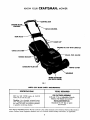
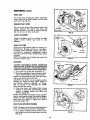
KNOW
YOUR
CRAFTSMAN
MOWER
ENGINE
CONTROL
DRIVE CONTROL
TRIM PLATE
BLE CLIP
ENGINE OIL CAP WITH DIPSTICK
GRASS
FUEL GAUGE
HANDLE
GASOLINE FILLERCAP
COVER
'HOUSING
WHEEL ADJUSTER
(ON EACH WHEEL)
FIG. I
MEETS
CPSC BLADE SAFETY
SPECIFICATIONS
REQUIREMENTS
TOOLS REQUIRED
FOR CATCHER ASSEMBLY
3/8 and 7/16 or Adjustable Wrench
Medium Flat Blade Screwdriver
Oil: Use SAE 10W30 motor oil. SAE 30
motor oil can also be used.
Gasoline: Use unleaded automotive gasoline. Regular automotive gasoline can also
be used. DO NOT use premium gasoline,
or gasoline containing alcohol.
FOR BLADE REMOVAL
Standard
15/16"
box or open
end wrench
Sears Rotary Walk-Behind Power Mowers conform lo the safety standards of the American National Standards
stitute, Outdoor Power Equipment Institute, and U.S. Consumer Product Safety Commission, as applicable.
3
In-
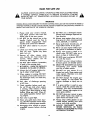
RULES FOR SAFE USE
CAUTION: ALWAYS DISCONNECT SPARK PLUG WIRE AND PLACE WIRE WHERE
IT CANNOT
CONTACT SPARK PLUG TO PREVENT ACCIDENTAL STARTING
WHEN SETTING--UP,
TRANSPORTING, ADJUSTING OR MAKING REPAIRS TO
YOUR MOWER.
_,
IMPORTANT
FEDERAL REGULATIONS REQUIRE THE ENGINE CONTROL INSTALLED ON THIS MOWER
MINIMIZE THE RISK OF BLADE CONTACT INJURY. DO NOT UNDER ANY CIRCUMSTANCE
DEFEAT THE FUNCTION OF THE OPERATOR CONTROL.
15. DO NOT use a damaged
mower.
Always have damage repaired before mowing.
1. Please read your owners manual.
Only allow persons who know the
safety rules to use your mower.
2. DO NOT tie the control bar to the
handle.
Control
must be free to
permit
brake
engagement
when
handles and control are released.
3. DO NOT allow
mower.
children
IN ORDER TO
ATTEMPT TO
16. Always stop engine when not cutting grass or when crossing grovel
drive, sidewalk, or roadway.
17. Never pull mower towards you, always follow mower to cut grass.
to use your
18. Never use your mower without proper guards or deflectors in place.
4. Check your mower over before each
time you mow. Tighten any loose
bolts, nuts, etc.
19. Always mow across a slope or inclined area. DO NOT mow up or
clown a slope or inclined area.
20. DO NOT mow in wet grass. DO NOT
run with the mower.
5. Remove
all sticks,
stones,
wires,
cans, boards, etc. from area to be
mowed.
These
objects
can
be
thrown by the blade.
21.
DO NOT run your mower indoors.
Exhaust gasses are deadly poison.
DRAIN THE GASOLINE tank before
6. DO NOT allow children, bystanders,
or pets in the mowing area.
7. BE CAREFUL - WHEN THE ENGINE IS
RUNNING THE BLADE IS TURNING.
22.
8. Always shut off engine before trying to adjust wheel heights.
23.
DO NOT run your mower if it vibrates too much. Stop engine and
make repairs. Vibration is an indication of damage.
24.
DO NOT" change the engine governor settings to over-speed
the
engine---damage
or injury can resuit.
25.
If a grass catcher is used on your
mower, check the catcher often for
damage.
Use only recommended
catcher. Always stop engine to remove grass catcher.
26.
DO NOT store your mower or gasoline where fumes may reach an
open flame and cause a fire.
13. Wear only solid shoes when mowing. DO NOT operate mower when
barefoot, or wearing open sandals.
27.
14. Disengage
28.
Always wear safety glasses or eye
shields before starting your lawn
mower and while mowing.
ALWAYS
DISCONNECT
BATTERY
BEFORE SERVICING
OR TRANSPORTING YOUR MOWER TO AVOID
ACCIDENTAL STARTING.
9. When engine is running, DO NOT
put hands or feet under mower or in
the discharge chute, nor make any
adjustments.
10. Stay clear of discharge opening
at all times.
transporting
your mower
your car or other vehicle.
f
11. Check gasoline before each use.
Do not fill gas tank when engine
is running, when indoors or when
engine is hot. Allow engine to cool
before filling gas tank. Wipe off
any spilled gasoline before starting engine.
12. Mow only in good
pro.pelled
engine.
light.
drive control
on power
mowers before
inside
starting
4
Theoperation
ofanylawnmower
canresultinforeignobjects
thrown
into
the eyes,
which can result in severe eye damage. Always wear safety glasses or eye shields
before starting your lawn mower and while mowing. We recommend Wide Vision
Safety Mask for over the spectacles or standard safety glasses, available at Sears
Retail or Catalog Stores.
ACCESSORIES TO HELP YOU GET THE MOST FROM YOUR MOWER
HIGH WHEEL KIT: A pair of 12-inch rear wheels improves handling on soft, spongy lawns and uneven
terrain. Includes height adjusters; doesn't affect cutting height range.
MOWER COVER: Sears Tyvek@cover protects mower from weather when stored outdoors.
GAS CAN: A new gas can keeps rust and dirt out of fuel systemfor longer engine life and improved performance. Craftsman qas cans have built in filters to keep impurities out of the engine.
MANUAL RECOIL STARTERKIT: A manual recoil starter kit is available thru Sears Service Department,
order Kit No. 35397 from Source 143.
CLIPPING DEFLECTOR:Converts rear bagging mowers to side discharge to disperse safely and evenly.
THESE ACCESSORIES WERE AVAILABLEAT MOST SEARSSTORES AND THROUGH THE CATALOG AT THE
TIME THIS MANUAL WAS PRINTED.
IMPORTANT
TIPS TO HELP YOUR LAWN MOWER START FASTER, RUN AND PERFORM BETTER
1. USE UNLEADED GASOLINE: It burns cleaner and leaves lessresidue in the engine. Regular gasoline can
also be used. DO NOT use gasoline containing any alcohol or with any additives.
2. DRAIN OR RUN-OUT ALL GASOLINE FROM TANK AT THE END OF THE SEASON: DO NOT leave gasolinein your mower when stored for long periods. It will "GUM" your engine. Run engine until the gasoline runs out.
3. START EACH MOWING SEASON WITH FRESHGASOLINE: DO NOT keep gasoline in your can. If your
gasoline can is starting to rust, replace can.
4. CHANGE YOUR SPARK PLUG EVERYSPRING: An aid, corroded spark plug prevents fast starting and
smooth running engine.
5. REPLACE YOUR AIR CLEANER OR FILTEROFTEN: Dirt, along with heat can harm your engine, the
cleaner or filter will clog up, preventing clean air from reaching your engine. See "Air CJeaner/Fitter"
section of this manual for replacing air cleaner or filter.
6. USE SAE 10W30 OIL: DO NOT use SAE 10W40 oil.
7. CHANGE OIL AS RECOMMENDED: IMPORTANT - change oil after the first two (2) hours of use, then
every 25 hours of use.
8. REPLACETHE BLADE WHEN NEEDED: You can sharpen the blade, but we do not recommend it. Erosion
from hitting foreign objects can damage the blade. Replace blade with one specifically designed
for your mower.
9. AT THE END OF THE SEASON, CLEAN YOUR MOWER: IMPORTANT- first disconnect the spark plug wire.
If possible, store your mower in a well ventilated area and protected from moisture.
10. FOLLOW THE MAINTENANCE SUGGESTIONS IN YOUR OWNERS MANUAL: Read your manual and
keep it in a convenient place for easy reference.
11. DO NOT PUT ANY ADDITIVES IN THE OIL OR GASOLINE: DO NOT USE GASOHOL, or gasoline containing any alcohol.
Your lawn mower has been completely assembled at the factory, except for the Grass Catcher and Grass
Catcher Frame. To set-up and attach Grass Catcher, follow the instructionsunder "TO UNFOLD HANDLE"
and "GRASS CATCHER".
The following parts are included not assembled:
I Grass Catcher Frame
I Grass Catcher Top
1 Grass Catcher Bottom
I Battery Charger
1 Hardware Package
t_'_._
'_._
t_
1
- UPRIGHT HANDLE-_r-'_
STORAGE
PO51TION
1
}-_
!
I
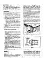
HOW TO SET-UPYOURMOWER
TO UNFOLD HANDLE
.O VlNO
POSITION
} x,2 L
POSmON
1. Raise the handles uritii the lower handle is in
mowing position (See Fig. 2).
NOTE: The lower handle automatically locks into
mowing position when raised from shipping to
mowing position.
2. Raise the upper handle into position on the
lower handle and tighten the two (2) handle
knobs.
LOW
HIGH POSITION
FOR TALL PERSON
POSITION
FOR SHORT PERSON
FIG. 2
\
LOWER
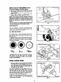
3. The handle can be mounted in high or low position to suit the comfort of the user. The handles are shipped mounted in the high position.
4. If the handle feels too high for you:
a. Remove the (4) screws and (2) bushings
holding the trim plate to lower handle.
Keep for reassembly (See Fig. 1).
b. Remove the handle knobs and bolts from
upper and lower handle.
c. Cut the wire tie and remove the cable
clip from lower handle. Keep cable clip for
reuse (See Fig. 4).
d. Remove the hairpin cotters and springs
from mounting pins (See Fig. 3).
e. Squeeze the bottom ends of the lower
handle toward each other until handle
and handle levers slip off mounting pins
(See Fig. 3).
f. Turn handle over, position the handle
levers in place (See Fig. 5).
g. Put handle back on mounting pins.
h. Put springs and hairpin cotters back on
mounting pins (See Fig. 3).
i. Put upper handle on lower handle using
" handle bolts and knobs previously removed.
j. Put trim plate back on lower handle removed in (a) above. Install the (4) screws
and (2) bushings (See Fig. 1).
k. Snap cable clip over cable-and lower
handle (See Fig. 1).
!. If you have cut the wire tie to turn lower
handle, locate the wire tie (black plastic)
in the customer package.
m. Install the wire tie over the cable sleeve
and lower handle, pull up snug and cut off
excess end of wire tie. (See Fig. 4).
5. To fold handle for storage, squeeze the handle
levers until lower handle clears handle brackets, then move handle forward (See Fig. 3).
HANDLE
SPR_NG
MOUNTING
PIN
HAIRPIN COTTER
//FIG. 3
CABLE
CLIP
WIRE
TIE
FIG. 4
IMPORTANT: WHEN FOLDING HANDLE FOR
TRANSPORTING OR STORAGE, BE SURE TO FOLD
HANDLE AS SHOWN IN FIG. 6. IF YOU FOLD HANDLE THE WRONG WAY, YOU MAY BEND THE
CONTROL CABLES.
CAUTION: ALWAYS DISCONNECT ENGINE CON-]
NECTOR FROM BATTERY TO PREVENT ACCI-I
DENTAL STARTING WHEN STORING OR TRANS-I
PORTING YOUR MOWER.
I
!
G
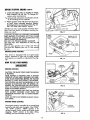
HOW TO SET-UPYOURMOWER(cam'D)
TAB
TO ADJUST HEIGHT OF CUT
NOTE: The wheels are set in a low position for shipment, and should be adjusted for the cutting
height desired before use.
CAUTION: DO NOT change the height of cut with
the engine running.
1. The wheel adjusters give you five (5) different
cutting positions. Medium cut is the best for
most lawns.
2. High cut is approximately 3 5/8", medium cut
isapproximately 2 1/2", and low cut isapproxh
imately 1 3/8". There are two other positions.
Pick the position which suits your lawn (See
Fig. 7).
3, The wheel adjusters on your lawn mower can be
easily adjusted as shown in Fig. 8. To change
the height of cut, squeeze adjuster lever toward the wheel, moving up or down to selected
height. Be sure all wheels are in the same
setting (See Fig. 7).
4. When cutting in heavy or moist grass, the rear
of the lawn mower may be raised one setting
higher to allow better discharge of the grass.
FIG. $
I
WAY
RIGHT:
WAY
S
_
"
WRONi
TO ASSEMBLE GRASS CATCHER
NOTE: The grass catcher for your mower is supplied unassembled.
To assemble your grass catcher follow steps below.
SCREWS ACTUAL SIZE
1/4-20 x 5/8"
SCREW
#10-24 x 5/8"
SCREW
1. Position clamp onto catcher frame as shown
in Fig. 9 and close ends of clamp.
NOTE: When closing clamp be sure the holes in
clamp are in line.
2. Put grass catcher frame with clamp installed
into catcher top as shown in Fig. 9.
3. Put one (1) #10-24 x 5/8 truss head screw
into hole in catcher top and clamp and #10-24
Iocknuts. DO NOT TIGHTEN (See Fig. 9).
4. Put three (3) #10-24 x 5/8 truss head screws
into the catcher frame using #10-24 Iocknuts.
Use a flat blade screwdriver to drive screws
while holding the Iocknuts with adjustable
or 3/8" wrench (See Fig. 9).
5. Position baffle inside of catcher top as shown
in (Fig.lO).Put two (2) #10-24 x 5/8 truss head
screws into holes with two (2) #10-24 Iocknuts.
Use a flat blade screwdriver to drive screws
while holding the Iocknuts with adjustable
or 3/8" wrench.
6. Position top half of catcher on the bottom
half (See Fig. 9).
7. Align the holes in sides of top and bottom
halves of catcher.
FIG. 6
8. Install the eight (8) 1/4-20 x 5/8" truss head
screws, starting at the right front of catcher
as shown in Fig. 9.
9. Install the 1/4.20 "Keps" nuts on the screws.
Do not tighten until all of the screws have
been installed in the catcher.
10. Use a medium flat blade screwdriver to
tighten the screws while holding the "Keps"
nuts with adjustable or 7/16" wrench.
NOTE: Check all screws and nuts to be sure they
are tight.
TO ATTACH GRASS CATCHER
1. Place the frame into the slot of the hinge
bracket.
2. Depress the door latch tab and slide the frame
into position at the end of the slot (See Fig.
11).
3. Release door latch tab to lock frame into place.
4. To remove grass catcher, SHUT OFF ENGINE,
lift up on back of grass catcher with one (1)
hand and pressdown on the door latch tab with
the other hand (See Fig. 11).
REMEMBER: Read your Owner's
Manual and Rules for Safe Use.
!
HOW TO SETUP YOURMOWER(€ONT'D)
TO ATTACH GRASS CATCHER (CONT'D)
5. When grass catcher frame isunlatched, remove
the catcher from the rear of the mower and
empty catcher.
6. When grass catcher is removed from the
mower, the rear door closes for safety.
OTE: YOUR REAR BAGGER MOWER IS NOT AI
ULCHING MOWER. DO NOT OPERATE YOURJ
OWER WITHOUT AN APPROVED GRASS CAT-I
ER OR OPTIONAL CUPPING DEFLECTOR INJ
CE.
WHEEL ADJUSTER LEVER
SHOWN
I
NEVER ATTEMPT TO OPERATE THE MOWER WITH
THE DOOR REMOVED OR PROPPED OPEN.
WITH
FIG.
WHEEL
REMOVED
7
REAR DEFLECTOR
The rear deflector,
attached
between the rear
wheels of your lawn mower, was assembled at the
factory and requires no assembly.
E-Z VIEW FUEL GAUGE
Your engine has a visual fuel gauge located on
top front of engine to indicate fuel level in tank
(See Fig. 12).
To read the gauge, look into the gauge when tank
is "EMPTY" a clear circle is seen. The 1/2 Full and
"FULL" will show dark or black in color to indicate
fuel level, see below:
RG. 8
TRUSS HEAD SCREWS-'-----_
_
I
CATCHERTOP
"F_'LL
I_
FULL
"E (PTY
CAUTION: When the full circle darkens to black,
use caution as the filler neck can over-fiow
quickly after gauge shows "FULL", if you continue
to pour into tank filler.
STARTHERE
,CATCHER
BOTTOM
FIG. 9
BEFORE
STARTINGENGINE
1. Remove engine oil cap with dipstick and fill to
the "FULL" line on the dipstick, using about 1
pint or 0.5 liters of Sears 10W30 oil or equivalent. SAE 30 oil can also be used (See Fig. 12).
DO NOT use SAE 10W40.
TRUSSHEAD SCREWS
The total oi! capacity of your engine is 21 oz. or
0.62 liters. Fill only to the "FULL"line on the dipstick. DO NOT over fill. The first fill on a new engine use about 1 pint or 0.5 liters. Check oil level
and add as required to bring to proper level.
2. Pour oil slowly, DO NOT over fill.
NOTE: On a new engine some oil may be left in the
engine, as each engine is run for operational
checks before shipping.
CATCHER BAFFLE
CUTAWAY OF CATCHER TOP
_
FiG. 10
8
LOCKNUTS |
i
BEFORESTARTINGENGINE(corn°!!
HINGE
BRACKET
3. AFTER THE FIRST TWO (2) HOURS OF MOWING CHANGE THE OIL. See "To Change Oil"
section under maintenance.
tse only oil with automotive classifications SF, SE,
• or SC markings on oil container.
4. Fill the gasoline tank with about two (2) quarts
of fresh, clean unleaded gasoline. Regular
leaded gasoline can also be used (See Fig. 12).
See "E-Z VIEW FUEL GAUGE" section.
DO NOT use old or stale gasoline which has been
kept from one season to another; starting problems can result.
DOOR LATCH TAB
FIG. ! 1
CAUTION: DO NOT USE GASOLINE CONTAINING
ANY AMOUNT OF ALCOHOL, AS IT CAN CAUSE
SERIOUS DAMAGE OR CAN SIGNIFICANTLY REDUCE ENGINE PERFORMANCE.
DO NOT USE PREMIUM LEADED GASOLINE.
DO NOT PUT ANY ADDITIVES IN THE OIL OR
GASOLINE.
Be sure your gasoline can is clean and free of
rust and dirt. Replace your can if it has started
to rust.
SPEED
CONTROL
KNOB
ENGINE OIL CAP
' WITH DIPSTICK
E-Z VIEW
FUEL GAUGE
ENGINE BLADE CONTROL
FILLER CAP
PRIMER
Your mower is equipped with an engine blade
control, attached to right side of upper handle
and requires no assembly or adjustment (See Fig.
i
ii
FIG. 12
15).
HOW TO USEYOURMOWER
JlMPORTANT !
ENGINE
CONNECTOR
ENGINE CONTROL
CAUTION: THE BLADE TURNS WHEN THE ENGINE
IS RUNNING.
YOUR MOWER IS EQUIPPED WITH A BATTERY
STARTING SYSTEM WHICH REQUIRES THE OPERATOR TO BE POSITIONED BEHIND THE MOWER
HANDLE TO START AND OPERATE THE MOWER.
THE CONTROL BAR MUST BE DEPRESSED TO THE
HANDLE TO START AND RUN THE ENGINE, RELEASING THE CONTROL BAR WILL STOP THE ENGINE. AN INTERNAL ENGINE BRAKEASSISTS THE
BLADE IN STOPPING QUICKLY.
NOTE: YOUR MOWER CAN ONLY BE STARTED
WITH BATTERY POWERED START FROM THE
OPERATORS POSITION. SEE "TO START ENGINE"
SECTION.
NOTE: DO NOT START ENGINE IN HEAVY OR UNCUT GRASS.
BATTE RY
CHARGER
BATTERY
BAI-rERY
./
_
CHARGER
CONNECTOR/y/
(FEMALI_
CONNECTOR
_ALE)
FIG. 13
___-
ENGINE
,___,__
CONNECTOR
ENGINE SPEED CONTROL
The engine speed is controlled by a control knob
located on top right side of engine. It has "HIGH"
,nd "LOW"
positions. "HIGH" position is for
Jtarting engine, heavy cutting and better grass
bagging. "LOW" position is for light cutting,
trimming and fuel economy (See Fig. 12).
FIG. 14
9
HOW TO USEYOURMOWER{€om'D)
CONTROtBAR%, \
TO PREPARE BATTERY
NOTE: YOUR BATTERYMUST BE CHARGED BEFORE YOU CAN START YOUR MOWER.
I. Connect battery charger connector (male) to
the battery connector (female) as shown in
Fig.13.
2. Plug the battery charger into 110 Volt-A.C.
outlet (See Fig.13).
3. Leave the battery charger connected for 24
hours before initially starting your engine.
4. After charging, connect engine connector to
battery connector (See Fig. 14).
Your engine has an integral alternator for partial
charging. Connect your battery charger to charge
battery as required.
THE ENGINE ALTERNATOR WILL NOT CHARGE A
DISCHARGED BATTERY.
_l
CONTROL
_
RELEASED
ENGINE
CONTROL
DEPRESSED
STOP
START-
RUN
FIG.15
_=___
L
CON/TROL BAR
At the end of the mowing season the battery
should be charged for 48 hours to protect the battery during winter storage.
ICAUTION:
ALWAYS
DISCONNECT
THE
ENG,NEI
ICONNECTOR
FROM
THE
BATTERY
CONNECTORI
FOPREVENT
ACCIDENTAL
STARTING
WHENt
IT NSPORTING
ORSTORING
YOUR
MOWERJ
FTER
THE
MOWING
SEASON.
I
__,_"_"
ENGINE!
BLADE BACK
DRIVE CONTROL
i
DISENGAGED
i
FIG. 16
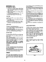
TO START ENGINE
NOTE: THE CONTROL BAR MUST BE DEPRESSED
TO THE HANDLE TO STARTAND RUN THE ENGINE.
NOTE: The carburetor has a fixed fuel mixture and
has a primer to assiststarting.
I. Check oil level; check gasoline level and make
sure spark plug wire is attached.
2. Move engine control lever to "HI" position (See
Fig. 12).
SPEED SEI
3. When starting a co/d engine, push the primer
five (5) times before attempting to start the
engine. Use sharp pushes and wait several
seconds between each push (See Fig. 12).
4. Repeat step 3 above as required.
NOTE: In cooler weather the need to repeat priming procedures may be necessary, when weather
is warmer over priming may result in flooding.
If you do flood engine wait a few minutes before
repeating priming procedures.
it is not normally necessary to use the primer to
start warm engine.
5. Position yourself at the handle, operator position.
FIG. I7
CAUTION: DO NOT crank engine more than five
(5) continuous seconds, each try to start, wait 5/10
seconds between starting attempts.
If engine fails to start after several attempts,
contact your nearest Sears Service Department
for help.
8. To stop engine, release the control bar (See
Fig. 15).
NOTE: The control bar must be held in "Depressed" position to keep engine running - when control bar is disengaged the engine will automatically stop (See Fig. 15).
6. Holding the control bar in depressed position,
with your right hand push in on the engine
start button (See Fig. 15). As the engine begins
to start, release the starter button. Engine will
stop when the control bar is released.
7. If the engine fails to start, repeat priming and
starting procedure.
10
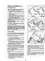
MOWING
HOW TO USEYOURMOWER(torn'D)
TIPS
1. Under certain conditions it may be necessary to
raise the height of cut to keep from overloading
the engine and leaving clumps of grass clippings.
2. For extremely heavy cutting, make the width
of your cut 1/2" to 3/4" the normal cut. This
will reduce the load on the engine and give you
cleaner cutting and bagging.
3. The user should note that when cutting moist,
heavy grass with a rear bagging mower,
dumps of cut grass may fail to enter the
grass catcher. To pick up the clumps, if they
occur, run the mower over the area a second
time.
"IF ENGINE DOES NOT START
1. Check engine control knob - is it in "HIGH"
position?
2. Check gasoline supply - put gasoline in tank.
3. Check spark plug wire
connect wire to spark
plug.
4. Check blade - remove spark plug wire when
checking blade. If blade is loose, see "BLADE
CARE" of manual for instructions on tightening
blade.
5. Check air filter - clean or replace if clogged.
See "AIR FILTER" section.
6. Check spark plug - if dirty, clean or replace.
7. Engine may be flooded - wait a few minutes
and repeat starting procedure.
8. Check battery
connection to engine starterconnect.
BLOCK OF WOOD_
NOTE: If then your engine will not start, contact
your nearest Sears Service Department
for help.
DRIVE CONTROL
With the engine running, the power-propelled
motion is controlled by pulling the drive control
lever until it clicks at which time the lever may be
released (See Fig. 16).
SPEED SELECTOR
FIG. 18
Your mower is equipped to give you (3) forward
speeds.
CAUTION: DO NOT move speed selector lever to
change speeds unless engine is running.
(1) (SLOW) speed for heavy cutting or trimming.
(2) Speed for normal cutting and walking speeds.
(3) (HIGH) for light cutting and fast walking speed.
Select the de_ired setting which suitsyou best by
pushing speed selector lever slightly to the left,
then to the speed desired (See Fig. 17).
BLADE FLANGE
CRANKSHAFT &
DETAIL
BCRANKSHAFT
SLOT
LADE NUT
BLADE WASHE!
POWER-PROPELLED DRIVE
BLADEFLANGE
AB
1. Your power-propelled drive is accomplished
by a belt drive from the engine crankshaft to
drive a worm and pinion gear case.
2. The drive belt isspring-loaded at the gear case
to maintain proper belt tension. Keep the area
around the gear case clear of trash by removing drive cover and cleaning (See Fig.
22 and 24).
3. The gear case is lubricated with multi-purpose
automotive grease. DO NOT USE ANY OTHER
type grease or oil in the gear case. See "GEAR
CASE" under "MAINTENANCE".
4. Check your mower, each time you mow, to be
sure that the front wheels turn freely. If wheels
DO NOT turn freely, remove any trash which
may have gotten into the wheel, pinion, or
bearing areas.
5. If at any time, the drive belt is replaced, use
only factory specified belt to get longer life
and maximum performance.
/
__DE
FIG. 19
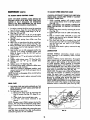
REAR DEFLECTOR
RG. 20
11
HOWTO USEYOURMOWER(€owo)
MOWING
TIPS. (CONI"D)
SCREW, q
4.
Under certain
pings may be
Mowing in a
overlap
will
lected on the
conditions a trail of _rass clipleft at the right side of the mower.
clockwise direction with a small
allow these clippings to be colnext pass.
I
MAINTENANCE
Be good to your mower. Once a year put on a
new mower blade, a new spark plug, and a new
air filter. A new blade cuts better. With a new
spark plug your engine will start and run better.
A new air filter assures proper air-fuel mixture.
It will help your engine run better and last longer.
FIG. 21
MOWER:
BLADE/BLADE FLANGE CARE
Use only a Sears authorized replacement blade to
get the best cutting results.
CAUTION: DISCONNECT ENGINE CONNECTOR]
FROM BATTERY CONNECTOR AND SPARKPLUGI
WIRE FROM SPARK PLUG. PLACE WIRE WHERE ITl
CANNOT COME IN CONTACT WITH SPARKPLUG.]
I
I. To remove the blade and blade flange, turn
mower on its side with the carburetor up (See
Fig. 18).
2. Take blade nut off by turning counter-clockwise. Use a 75/16" box or open end wrench on
the blade nut (See Fig. 18).
3. Put a block of wood between the blade and
mower housing toprevent blade rotation when
removing and tightening blade nut.
NOTE: Always check the blade flange when
changing the blade to be sure tab has not been
damaged (See Fig. 19).
4. If the tab in the blade flange is damaged
replace the blade flange.
NOTE: The blade flange with tab attaches the
blade to crankshaft. It is not intended to protect
the crankshaft. The tab must be in good condition
and located in slot of crankshaft to keep blade
attached.
F_G.
_t_ _
5. Put the blade flange on the engine crankshaft
with the tab in the slot of the crankshaft (See
Fig. 78).
6. Put the blade on the crankshaft as shown in
(Fig. 18). Be sure the word "TOP tl (stamped
in the blade) is toward the engine.
REAR DEFLECTOR
FIG.23
The rear deflector which is attached to the rear of
your mower is to keep objects from being thrown
cJutthe back of the mower. If your rear deflector
becomes damaged you should replace it (See
REMEMBER: Read your Owner's
Manual and Rules for Safe Use.
Fig.20).
12
1
k
MAINTENANCE
[(ONT'D)
TO ADJUST SPEED SELECTOR CABLE
TO ADJUST DRIVE CONTROL CABLE
CAUTION: DISCONNECT SPARKPLUG WIRE FROM
SPARK PLUG. PLACE WIRE WHERE IT CANNOT
CONTACT SPARK PLUG.
NOTE: THE DRIVE CONTROL CABLE SHOULD BE
CHECKED OFTEN TO BE SURE THAT GEAR CASE
SHIFTER IS FULLY ENGAGED OR WHENEVER
SERVICE HAS BEEN PERFORMED ON THE GEAR
CASE OR DRIVE CONTROL COMPONENTS.
1. While cranking engine with engine control
move speed selector lever to (3) high position
(See Fig. 17).
NOTE: DISCONNECT THE ENGINE CONNECTOR
FROM THE BATTERY TO PREVENT ACCIDENTAL
STARTING.
2. Remove the drive cover by removing (4) screws
(See Fig. 21).
3. Loosen both jam nuts on cable end (See Fig.
24).
4. Pull on control cable until belt is snug and
tighten rear jam nut up to bracket, then turn
jam nut (2) full turns.
5. Turn front jam nut up to bracket, then hold
the rear jam nut with 1/2 wrench while tightening the front jam nut with a I/2" wrench
(See Fig. 24).
6. Put drive cover back in place, removed in step
(2) above.
1. To adjust, remove the drive cover by removing
four (4) screws. Keep for re-use (See Fig. 21).
2_ Loosen screws holding cable clamp "A" & "B"
(See Figs. 22 and 23).
3. Loosen both jam nuts "C" & "D" at the cable
- clamp on the gear case adjusting bracket (See
Fig. 22_).
.
4. Unhook clutch spring from shifter arm (See
Fig.
5. Hold, clip, or tape down the drive control bar
and engage the drive control (See Fig. 16).
6. Move the shifter arm to drive position. To be
sure the jaw clutch is fully engaged, rotate the
front wheels.
7. Hold shifter arm in fully engaged position by
gripping and pulling threaded sleeve with
pliers as shown in Fig. 22. DO NOT pull on
control cable.
8. Tighten jam nut "C" up to bracket until cable is
snug.
9. Tighten cable clamp screw "B" (See Fig. 22).
10. Tighten jam nut "D" up to bracket (See
Fig. 22).
1I. Tighten screw "A" (See Fig. 23,).
12. Put clutch spring back in place on shifter arm,
removed in step 5 above.
73. With drive control in engaged position, push
mower back and forth to be sure gear case is
fully engaged.
NOTE: Be sure to disengage drive control before
starting engine.
14. Put drive cover back in place, removed in step
I above.
LUBRICATION
MOWER WHEELS: Lubricating wheels and/or
wheel bearings is not necessary under normal
conditions.
Should conditions require lubrication, thoroughly
clean wheels and/or wheel bearings and axles,
then apply a light coating of dry lubricant such
as white graphite. White graphite is available
at Sears retail stores and through the catalog.
REAR DOOR HINGE: Put a few drops of the same
oil as used in the engine on hinge points of rear
door once or twice each year (See Fig. 25).
GEAR CASE: The gear case is filled at the factory
and does not require an addition of lubricant,
unless the gear case is opened and service
performed. Use only a multi-purpose automotive
grease for refilling after service has been performed. Approximately 2 1/2 oz. required.
FRONT WHEEL ADJUSTERS:Put a few drops of the
same oil as used in the engine on the front wheel
adjusters once or twice each year (See Fig. 26).
GEAR CASE
7. THE GEAR CASE AND AREA AROUND ALL THE
DRIVE SHOULD BE KEPT CLEAN AND FREE OF
TRASH BUILD-UP.
2. To check gear case area:
a. Remove the drive cover by removing the
four (4) screws (See Fig. 21). Keep for reuse.
b. Clean trash from around gear case.
c. Put drive cover back, removed
in (a)
above.
DRIVE PULLEY
JAM NUT
/
JAM NUT
NOTE: The gear case is filled to proper level at the
factory. The only time the lubricant needs attention is if service has been performed on the gear
case.
The gear case must be filled with grease after gear
case has been serviced. Use only multi-purpose
automotive grease. Do not substitute.
FIG. 24
13
MAINTENANCE(€orn,o)
IDLER ARM
Put a few drops of same oil used in engine between idler arm and flat washer, once or twice
each year (See Fig. 27).
ENGINE START LEVER
Put one
engine
bracket
29). Do
or two drops of the same oil used in the
between the engine start lever and
located on left rear of engine (See Fig.
this once or twice each year.
OIL HERE
REAR
FIG. 25
CHECK FASTENERS
Check all fasteners and be sure they are tight.
Tighten and/or
replace any loose or worn
fasteners.
COTTER
GRASS CATCHER
Check your grass catcher often for damage or
deteriorcrlion. Through normal use it will wear.
If catcher needs replacing, replace only with a
manufacturer approved replacement
catcher
from Sears. Give the mower model number when
ordering.
NOTE: The catcher may be hosed with water, but
must be dry when used.
WHEEL
OIL HERE
EACH SIDE
HUBCAP
FIG. 26
CLEANING
i
IDLER
CAUTION: DISCONNECT ENGINE CONNECTOR
FROM BATTERYCONNECTOR AND SPARK PLUG
WIRE FROM SPARKPLUG. PLACE WIRE WHERE IT
CANNOT COME IN CONTACT WITH SPARKPLUG.
DRIVE PULLEY
1. Turn mower on its side with carburetor up.
2. Clean the underside of your mower by scraping to remove build-up of grass and trash.
NOTE: We recommend that you clean the underside of your mower after each use.
CAUTION: The muffler on your engine extends
through the mower housing. Allow engine to
cool before cleaning underside of mower.
Also be careful to not damage the muffler
when cleaning the mower.
3. Clean your mower and engine often to keep
build-up of trash from accumulating around
engine, a clogged engine runs hotter and
shortens engine life.
NOTE: We DO NOT recommend using a garden
hose to clean mower unless the electrical system,
muffler, air filter, and carburetor are covered to
keep water out. Water in engine can result in
shortening engine life.
FIG.'27
NUT
BLADEFLANI
i.--N
GEAR CASE AND DRIVE WHfELS
PULLEY
BOTTOM COVER
NOTE: The gear case and drive wheels should be
caced for much like you would an automobile.
1. On a regular schedule remove the drive cover
and remove any trash around gear case and
belt area.
ii
FIG.28
14
MAINTENANCE(€om'o)
The total oil capacity of your engine is 21 oz. or
0.62 liters. Fill only to the "FULL" line on the
dipstick. DO NOT over fill. The first fill on a new
engine use about 1 pint or 0.5 liters. Check oil
level and add as required to bring to proper level.
NOTE: On a new engine some oil may be left in
the engine, as each engine is run for operational
checks before shipping.
Use Sears SAE 10W30 oil or equivalent. SAE 30
oil can also be used. DO NOT use SAE 10W40 og.
GEAR CASE AND DRIVE WHEELS, (€OHT'D)
2. To remove drive cover, remove the four (4)
_crews (See Fig. 21). Keep for re-use.
_. Keep your mower
clean and properly
lubricated.
DRIVE WHEELS
NOTE: Check front drive wheels each time before
you mow, to be sure they move freely.
1. The wheels not turning freely indicates trash,
grass, cuttings, etc. are in the drive wheel
area, and must be cleaned to free drive
wheels.
2. If necessary to clean the drive wheels (See Fig.
26) check both front wheels.
a. Remove hub caps, hairpin cotters and
washers. Keep for re-use.
b. Remove wheel from wheel adjusters.
c. Remove any trash, grass cuttings from
inside the dust cover, pinion and!or drive
wheel gear teeth.
d. Put wheels back in reverse of removal.
3. If after cleaning drive v.heel area, the drive
wheels DO NOT rotate freely, the gear case
needs care.
Use only oil with automotive classifications SF, SE,
SD, or SC markings on oil container.
Using Sears SAE 10W30 oil will assistengine starting in cool weather.
Running your engine with oil below safe level or
with dirty contaminated oil can contribute to shortening the fife of your engine.
After the first two (2) hours of mowing change the
oil, then change the oil every 25 hours of mowing
• thereafter. If you mow under very dusty, dirty
conditions you may need to change the oil more
often.
NOTE: If your gear case requires service we
suggest that you contact Sears Service Center.
1"O CHECK AND/TO
START LEVER
REPLACE BELT
\
I. Remove the drive cover by removing the four
(4) screws (See Fig. 21).
2. Inspect belt for wear or damage. If you decide
to replace:
a. Remove belt from drive pulley and remove
belt from idler pulleys (See Fig. 27).
3. Turn mower on its side with carburefor up.
4. Loosen and remove the (4) phillips head screws
holding bottom cover to underside of mower
housing (See Fig. 28).
5. Remove the bottom cover down to rest on top
of blade flan_e.
6. Remove belt trom vari-speed pulley on crankshaft, and carefully remove the belt off over
bottom cover and blade (See Fig. 28).
CAUTION: The sharp edges of blade can cut the
belt. Use care when installing new belt over blade.
7. To install new belt, reverse procedure as above
in removal.
8. Put bottom cover back up in place and install
the (4) screws and tighten.
9.r Put drive cover back in place, removed in step
(1) above.
NOTE: Always use only factory approved belt to
assure proper fit and longer life.
FIG. 29
_G. 30
TO CHANGE OIL
ENGINE:
LUBRICATION
CAUTION: DISCONNECT ENGINE CONNECTOR
FROM BATTERY CONNECTOR AND SPARK PLUG
WIRE FROM SPARKPLUG. PLACE WIRE WHERE IT
CANNOT COME IN CONTACT WITH SPARKPLUG.
ENGINE: Use of proper oil in your engine and
keeping to full level is essential. Changing oil regularly will lengthen the life of your engine.
1. Remove engine oil cap with dipstick, lay aside
on a clean surface. Warm oil drains better.
15
If your engine is not to be used for 30 days or more
prepare as follows:
Drain gasoline from fuel tank; gasoline left in gasoline tank and carburetor will form deposits and
cause problems in starting and running your
engine.
MAINTENANCE
(€am'i))
TO CHANGE
OIL (CONT'D)
2.
Tip mower on its side as shown in Fig. 30 and
drain oil into suitable container. Rock mower
back and forth to remove any oil trapped
inside of engine.
3. Wipe off any spilled oil on mower and/or
inside of engine.
4. Fill engine with oil, fill only to the "FULL" hne
on the dipstick. DO NOT over fill.
5. Reconnect spark plug wire to spark plug.
Run engine until gasoline tank is empty and engine
stops running.
When preparing your mower for storage it is a
good time to service your mower and engine to be
ready for the next mowing season. Replace such
parts as mower blade, spark plug, and air filter
CHANGE OIL: Warm oil drains better.
Drain old oil and replace with fresh clean Sears
SAE 10W30 oil.
See "To Change Oil" section under Maintenance.
Remove spark plug and put 2 or 3 tablespoons of
oil into spark plug opening and pull starter rope
slowly to disthbute oil, install new spark plug
and tighten.
DO NOT PUT ANY ADDITIVES IN GASOLINE OR
OIL.
AIR FILTER
CAUTION: DO NOT run your engine without air
filter in place.
1. Your engine will not run properly with a clogged, dirty air filter.
NOTE: DO NOT wash this paper type air filter.
2. Replace your air filter each year, more often if
you mow in very dusty, dirty conditions.
SPARK PLUG
CLEAN MOWER/ENGINE
Change your spark plug each year.
A new clean spark plug will make your engine start
and run better. Keep your spark plug clean. Set
spark plug gap at .030.
Recommended
replacement
Sears spark plug no.
7133312 or STD361458
are available
at most
Sears retail stores and through the catalog.
CAUTION: Before cleaning mower, disconnect
spark plug wire and place wire where it cannot
come in contact with the spark plug.
Clean around engine and on top of mower.
Scrape underside of mower using putty knife or
similar tool to remove any build-up of trash or
grass on underside of mower housing.
NOTE: We DO NOT recommend using a water"
hose to clean your mower unless the electrical
system, muffler, air filter and carburetor are
covered to keep water out. Water in engine can
result in shortening engine life.
BATTERY CARE
To charge battery, DO NOT use any other type
battery charger than the charger included with
your mower.
NOTE: Additional charging during the mowing
season may be necessary.
At the end of the mowing season the battery
should be charged for 48 hours to protect the
battery during winter storage.
CAUTION: ALWAYS DISCONNECT THE ENGINE
FROM BATTERY CONNECTOR,
TO PREVENT
ACCIDENTAL STARTING WHEN STORING OR
TRANSPORTING YOUR MOWER.
CHECK FASTENERS
Check all fasteners and be sure they are tight,
tighten and/or
replace any loose or worn
fasteners.
GENERAL
DO NOT use gasoline left over from previous season. Old or stale dirty gasoline can cause starting
and running problems.
Replace your gasoline can, if your old can starts to
rust. DO NOT use rusty gasoline can, rust and/or
dirt in your gasoline can cause problems.
STORAGE
Never store engine
with gasoline
in tank, indoors
FIG. 31
or in closed, poorly ventilated areas where gasoline fumes may reach an open flame, spark or pilot
light as on a turnace, water heater, clothes dryer,
etc.
16
STORAGE
(comoo)
GENERAL
GRASS CATCHER
Always store your mower on its wheels. Storing
mower on its side or end, may result in difficult
starting.
When removing your mower from storage, fill
gasoline tank with fresh, clean, unleaded, automotive gasoline. Check and fill oil to proper level.
When starting your engine the first time after being in storage for extended period, the engine
may smoke for a while until the engine burns any
oil or gasoline accumulated during the storage
period.
DO NOT store gasoline from one season to another. Use up or dispose of any unused gasoline
left from the mowing season.
Replace your gasoline can if your can starts to rust.
DO NOT use rusty gasoline can. Rust and/or dirt
in your gasoline i:an cause problems.
DO NOT store your mower under any plastic cover,
plastic cannot breath which promotes condensation and can cause your mower to rust.
Check your grass catcher often for damage or
deterioration.
Through normal use it will wear.
if catcher needs replacing, replace only with a
manufacturer approved replacement catcher
from Sears. Give the mower model number when
ordering.
NOTE: The catcher may be hosed with water, but
must be dry when used.
REPLACE BLADE
See "Blade Care" section under Maintenance.
To ge_ the best cutting resultswe recommend that
you replace your blade with a Sears original
equipment blade each year.
Replacement blade is available at most Sears
stores and through the catalog. Be sure to give
your mower model number when ordering blade.
We DO NOT recommend sharpening blade - you
can keep the cutting edge touched up with a file.
Grinding the cutting edge excessively can cause
the blade to be out of balance. An unbalanced
blade can cause excessive vibration and shorten
the life of the engine and mower.
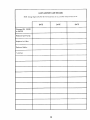
LAWN
NOTE: Change
Engine
Oil after
MOWER
HANDLE
You can fold your mower handle for storage (See
ie. 37).
When setting-up your handle from storage position the lower handle will automatically lock into
mowing position.
CARE RECORD
the First two (2) hours of use, and then every 25 hours of use
DATE
DATE
ii
.11.
Changed Oil: 10W30
or SAE 30
ill
Replaced spark plug:
Replaced air filter:
iJ
i
Replaced blade:
ii
Tuned-up:
_7
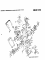
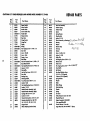
CRAFTSMAN
22" POWllR-PROPELLED LAWN MOWER MODEL NUMBER 917.374400
REPAI R PA RTS
39
22
--66
38
65
_3
39
13
63
*ilUtlBE NUT TIGHTENING TORQUE 5065
FT.
AFTS,AN
22"POW R., O,S
LAW.
O ,OW R
,OO L
.U,m 9,7.374400
Ref.
No.
Part
No.
ii
1
2
3
4
5
6
7
8
9
10
!!
12
13
14
15
16
17
18
19
20
21
22
23
24
25
26
27
28
29
30
31
32
33
34
35
36
37
38
857s5
84683
63688
85827
STD523117
51793
77524
81027
77526
77527
5TD581025
STD512505
83935
81281
85535
62363
86412
STDS12S05
85877
STDSI2505
63601
77514
81283
77521
85546
85354
STD511005
69180
57917
63601
86156
86157
66238
63124
55187
48014
85463
69478
Part
i
iiii
Name
i
Ref.
Part
No.
No.
i
Upper Handle
Lower Handle
Handle Knob
Control Cable Clip
Handle Bolt
Hairpin Cotter
Rear Dear
Hinge Bracket
Hinge Rod
Spring
E-Ring
Hex Tapping Screw 1/4-20 x !/2
Door Seal
Lever - Handle
Lever- Knob
Spring - Lever
Back Plate
Hex Self Tapping Screw I/4-20 x 1/2
Back Plate Bracket
Hex Head Machine Screw I/4-20 x I/2
Lecknut 1/4-20
Side Baffle
Hex Self Tap Screw 10-24 x 3/8
Rear Skirt
Backing Strip
Discharge Baffle
Truss Head Screw_10-24 x 1/2
Locknut 10-24
Hex Head Machine Screw !/4-20 x 3/4
Lecknut I/4-20
Handle Bracket Assembly (Left)
Handle Bracket Assembly (Right)
Carriage Bolt 5/16.18 x 5/8
Locknut 5/16-18
Thread Cutting Screw 5/16-18 x 3/4
Housing Assembly (Incl. Ref. #17,
18, 19, 20, 21, 22, 23, 37, 59)
Danger Decal
Wheel Adjusting Bracket (Rear)
REPAIR PARTS
Part Name
i
39
40
41
42
43
44
45
46
47
48
49
50
51
52
53
54
55
56
57
58
59
60
61
86107
84888
77865
84920
62335
84921
74400
86455
82854
52160
55015
85313
85962
84083
63601
703_5
81276
86O02
86448
86701
85283
85948
68205
62
63
64
65
66
67
68
69
70
71
72
73
51433
54867
69385
69334
84918
85947
8S946
85945
52828
79982
65053
86101
86422
Axle Arm Assembly
Selector Spring
Selector Knob
Spacer
Spring Washer
Shoulder Bolt
Locknut 3/8-16
Bearing
Washer
_
,
/'_._._,_
°r!._"
Retainer Clip
HubC.p
Bracket
Screw 1/4-20 x 5/8
Locknut 1/4-20
Cable Clip
Self-Tapping Screw 10-24 x I/2
Bottom Cover
Push In Nut
Hex Tapping Screw #10 "" LU_,._
Front Baffle
Belt Guide
Hex Head Machine Screw
5/16-18 x 7/8 (Special)
*Locknut 5/8-18 (Special)
Spring Washer
Washer
Blade
20
_'t_,>'7_'"
Blade Flange
Retaining Ring
Washer
Spring
Set Screw
Pulley Halves Kit (Incl. Ref. #67)
Woodruff Key #6
Engine Assembly 143.364052
(See pages 26thru28)
Owners Manual - Parts Ust
High Wheel Kit (Not included) 71 33721
L_-_<.
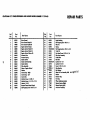
C..S.AN22".)WBR-PROmLSO
LAWN
.OW_..OOSL
.U.BE.9,7.374400
REPAIR PARTS
12
18
85
1.5
7
29
19
26
34
77
77
46
55
56
39
78
78
73
74
51
48
4:
53
4t
I
82
46
47
39
52
49
61
I
4
CRAFTSMAN
REPAIR PARTS
22" POWER-PROPELLED LAWN MOWER MODEL NUMBER 917.374400
Ref.
No.
Part
No,
1
2
3
4
5
6
7
8
9
10
11
12
13
14
15
16
17
18
19
20
21
22
23
85759
79875
7998O
86339
480OO
48001
48O02
86643
86642
86644
86645
86646
86647
86648
85723
85690
85691
85548
85692
86O55
53490
86591
78O9O
Part Name
Ref.
No.
Part
No.
iii
Drive Control
Drive Control Heed Kit
Drive Control Cable Kit
Engine Control CompI.
Engine Control Heed Kit
hgine Central Cable Kit
Engine Control Halves Kit
Actuator Cam
Actuator Spring
Starter Switch
Starter Switch Spri_
Starter Balton
Wire Assembly
Sleeve - Engine Control
Washer
Control Cap - Right
Control cap. Left
Control Bar
Machine Screw 1/4-20 x 2
Machine Screw ]/4 - 20 x 2 I/4
Locknut 1/4-20
Remote Control Panel Campl.
Self.Tapping Screw 10-24 x 3/4
24
25
26
27
28
29
30
31
•32
33
34
35
36
85529
85825
66426
83700
STD60 ! 003
85954
83813
B6027
75672
75673
STD541537
68478
58962
37
38
39
40
41
42
43
44
45
46
75674
86691 _52160
55015
77400
86275
77862
77861
77858
Part Name
II
JII
Nylon Bushing
Self-Tapping Screw I 0-24 x !
Wire Tie
Clamp
Self-Tapping Screw 10-24 x 3/8
V-Belt 3L
Hex Head Screw 10-32 x 5/16
Idler Arm Assembly
V-Belt idler
Flat idler
Lacknut 3/8 - 24
Lecknut 5/16-18
Screw 5/16-18 x 3/4
Idler Beming
Flat Washer
Wheel & Tire Assembly 8.00
Washer
Retainer Clip
Hub Cop
Wheel Adjusting Bracket
Selector Spring (Right)
Selector Spring (Left)
Axle Arm Assembly
REPAIR PARTS C(0.T'D)
CRAFTSMAN 22" POWER-PROPELLED LAWN MOWER MODEL NUMBER 917.374400
Ref.
No.
Part
No.
Part Name
i
47
4_3
49
50
51
52
53
54
55
56
57
58
59
60
61
62
63
64
65
66
67
68
69
86273
STD582087
86274
77865
61528
63601
76401
STD580014
74507
STD581050
81612
81220
85963
77828
86012
79949
74976
85950
STD580009
75192
68038
81206
STD522515
Ref.
No.
Part
No.
70
71
72
73
74
79994
Part Name
i
Spacer Bearing
Retaining
Ring
Spring Washer
Selector Knob
Flnt Head Machine
Screw 1/4-20
x 3/4
Locknut !/4-20
Dust Cover
Woodruff Key #3
Pinion
E-Ring
___
Lockwasher
Shoulder Nut
Drive Cover
Pan Head Machine Screw 10-24 x 1/2
Drive Shaft Tube
Gear Case Replacement Kit
Retaining Ring
Drive Pulley
Woodruff Key #213
Spring
Locknut 1/4-20
Spacer
Hex Head Bolt 1/4-20 x I 1/2
iiii
79995
85428
84164
Wheel Adjuster Assembly (Left)
Wheel Adjuster Assembly (Right)
Catcher Top
Catcher Bottom
Catcher Baffle
75
83548
84806
76
12024
Truss Head Machine
Screw
83555
1/4-20
x 5/8
Truss Head Machine
Screw
69180
10-24 x 5/8
Lecknut 10-24
53838
Keps Nut
83553
Clamp
85878
Clipping
77
78
79
80
81
Catcher
Frame
!/4-20
Deflector
Accessory
(Not In_:luded w/M_wer)
82
83
84
85
86
86593
48013
86592
77828
86408
Controll Bracelet Assembly
Cable _sse_bly
Remot¶Control
Tapping Screw
Panel
Grass Catcher Complete- 7133463 (Not Included)
High Wheel Kit No.7133721
(Not Included )
Instruction Decal
_
# I
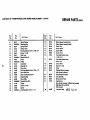
CRAFTSMAN 22" POWER-PROPELLED LAWN MOWER
MODEL NUMBER 917.374400
REPAIR PARTS
17
t
10
2O
!
4
r
Ref.
No.
Part
No.
[11
1
2
3
4
5
6
7
8
9
10
11
12
13
53838
85178
83488
57072
57388
79899
77881
77039
79946
57079
75144
53912
81203
Ref.
No.
Part Name
Part
No.
Part Name
i[
Locknut I/4-20
Adjusting Bracket
Shifter Assembly
Seal
Driv-Lok Pin !/8" x !/2"
Gear Case Halves
(incl. Upper and Lower Halves)
Bearing
Spring Bracket
Drive Shaft Kit
Thrust Washer
Yoke. Clutch
Driv-Lok Pin I/8" x 5/8"
Washer, Non-Metallic
14
81377
15
81337
16
-83659
17
75424
18
58354
19
STD581050
20
83684
21
83720
22
65692
23
24
83680
23
STD522512
Hex Wctsher Head Machine Screw
3/8-16 x 3_1_'
Seal - Shifter
Helical Gear
Jaw Clutch
Grease (1 lb. can - Shell Darina AX)
E-Ring - I/2 Shaft
Square Key
Worm Shaft
Woodruff Key #3
Worm
Hex Head Machine Screw
1/4-20 x 1 1/4"
CRAFTSMAN
22" POWER-PROPELLED
LAWNMOWER
MODELNUMBER9 ! 7.374400
REPAIR PARTS
®
I
Ref.
No,
Part
No.
6
Part Name
11
1
2
35355
86532
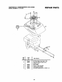
Gas Cap (Order From Source 143)
Acorn Hex Washer
#10-24
3
4
5
6
Head Screws
x 5/8
66454
Shroud Grill
Shroud / Tank Assembly
86661
Tank Bracket Assembly
86399
Hex Head Tapping
86345
24
Screw 1/4-20
x 1/2
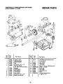
REPAIR PARTS
CRAFTSMAN 22" POWER-PROPELLED LAWN MOWER
MODEL NUMBER 917.374400
Ref.
No.
Part
No.
1
2
3
4
5
6
86335
86338
86336
86344
86353
86342
Part Name
Battery Bracket
Battery Cover
Battery
Slotted Hex Head Screw 10-24 x 1/2
Connector Mounting Clip
Battery Charger
25
(RAFT_N
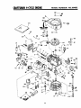
4-(YGE ENGINE
173
51
\
149
I/47
MODEL
NUMBER:
143.364052
CRAFTSMAN
4"CYCLE
ENGINE
Ref.
No.
Part
No.
1
3
4
5
5
3518O
26727
32600
29314B
29315C
6
6
29313C
29315C
8
9
10
11
12
14
31671
31672
31673
35175
32323
34851
14
34852
14
34853
14A
14A
32603B
32604B
14A
32605B
15
15
15
16
17
18
21
22
34854
34855
34856
20381
30963B
32610A
27241
33553
23
24
25
29914
"35261
35362
26
27
28
27897
*28833
3O572
650488
3O590A
30574
3O591
29193
3O598A
31335
30589
28277
31393A
31361
65O548
611004
29443
"33015
34342
6021A
35078
30
31
32
33
34
35
36
37
38
39
4O
41
42
47
51
52
54
57
59
*27234
32755
3O2OO
34215
*32760
650125
*34690
35363
650451
26460
MODEL
NUMBER:
143.364052
Ref.
No.
Part Name
Cylinder Assy, (loc!. Nos. 3 8- 41
Pin, Dowel
Seal, Oil
Valve, Intake (Std.) (Incl. No. 10)
Valve, Intake (1/32" oversize) (Incl.
No. 10)
Valve, Exhaust (Std.) (Incl. No. 10)
Valve,
Exhaust
(1/32"
oversize)
(Incl. No. 10)
Cap, Upper valve spring
Spring, Valve
Cap, Lower valve spring
Crankshaft
Washer, Thrust
Piston, Pin 8- Ring Assy. (Std.) (Incl.
Nos. 14A, 15 _ 16)
Piston, Pin 8. Ring Assy. (.010 oversize) (Incl. Nos. 14A, 15 8. 16)
Piston, Pin _t Ring Assy. (.020 oversize) (Incl. Nos. 14A, 15 8- 16)
Piston 8- Pin Assy, (Std.) (Incl. No. 16)
Piston _ Pin Assy. (.010 oversize)
(Incl. No. 16)
Piston 8" Pin Assy. (.020 oversize)
(Incl. No. 16)
Ring Set, Piston (Std.)
Ring Set, Piston (.010 oversize)
Ring Set, Piston (.020 oversize)
Ring, Piston pin retaining
Rod Assy., Connecting (Incl. No. 18)
Screw, Connecting rod
Lifter, Valve
Camshaft
(Mech.
Compression
Release)
Pump Assy., Oil
Gasket, Mounting flange
Flange Assy., Mounting (Inc!. Nos. 26,
27, 28 8. 32)
Seat, Oil
Gasket, Oil drain plug
Plug, Oil drain
Screw, Hex hd. Seres, 1/4-20 x 1-1/4
Washer, Flat
Shaft, Mechanical governor
Gear Assy., Governor (Incl. No. 31)
Ring, Retaining
Spool, Governor
Clamp, Governor lever
Rod, Governor [tncl. No. 38)
Washer, Flat
Lever, Governor
Spring, Governor
Screw, Hex washer hd., 8-32 x 5/16
Key, FlU/wheel (Solid State)
Clip, Spring
Gasket, Cylinder head
Head_ Cylinder
Screw, Hex flange hd., 6/16-18 x 1-I/2
Plug, Spark (Autolite 458, Champion
J-19LM or equivalent)
Gasket, Valve spring cover
Cover, Valve spring box
Screw, Hex washer hd. Seres, selftapping, 10-24 x 9/16
Breather Assy. {IncL Nos. 54 8. 56)
Gasket, Breather
Screw, Fil. hd. Sems, 10-24 x 1/2
Gasket, Intake pipe
Pipe, Intake
Screw, Hex hd. Sems, 1/4-20 x t
Clamp, Fuel line
Part
No.
67
70
71
34357
34337
3O2O0
72
73
74
75
76
33802
31342
65O777
65O549
33970A
77
78
80
83
85
86
87
88
89
98
99
35369
35364
34961
*26756
6201
29752
35367
35O68
32796
35366
650831
100
3O2O0
102
106
I07
118
119
120
121
122
123
35355
650815
65O816
34443A
650814
35172
650869
35171
65O562
124
125
126
127
132
133
650767
135
136
137
141
14Z
143
144
145
145
147
610118
34O8O
61I044
35O15
34965
34966
323O9
34968
61O973
65O831
148
149
150
170
172
173
34977
35356
610921
632420
34934
33236B
34285
34380
35368
Part Name
Une, Fuel
Link, Governor spring
Screw, Hex washer hd. Seres, selftapping, 10-24 x 9/16
Spring, Compression
Spring, Compression
Screw, Fil. hd., 632 x 17/32
Screw, Ffl. hd., 5-40 x 7/16
Control Assy,, Speed (incl. Nos. 72,
73, 74 8 75)
Knob, Speed control
Link, Governor-to-throttle
Wire, Ground
Gasket, Carburetor
Screw, Hex hd., 1/4-28 x 7/8
Nut £t Lockwasher, 1/4-28
Tube, Air cleaner
Clamp, Air cleaner
Filter, Air cleaner
Housing, Blower
Screw, Hex washer hd. Powerlok
thread, 1/4-20 x 1/2
Screw, Hex washer hd. Sems, selftapping, 10-24 x 9/16
Cap, Fuel tank
Washer, Belleville
Nut, Flywheel
Solid State Assy.
Screw, Hex hd. Seres, 10-24 x I
Muffler
Screw, Hex hd., 1/420 x 2-3/4
Plate, Lock
Screw, Hex washer hd. shake-proof,
10-32 x 1/2
Gasket, Fill tube
Tube Assy., OiJ filler
"O" Ring
Dipstick, Oil (Incl. No, 126)
Coil Assy., Alternator
Screw, Hex hd. Sems taptite, 8-32 x
5/8
Cover, Spark plug
Spacer, Flywheel key
Flywheel
Bracket Assy., Brake
Spring, Extension
Link, Control
Ring, Retaining
Lever, Brake
Terminal Assy.
Screw, Hex washer hd. Powedok
thread, I/4-20 x 1/2
Connector, Double wire
Wire, Ground
Connector Body
Carburetor (Ind. No. 83|
Motor, Electric Starter
GasketSet (Incl. items marked *)
*Indicates Parts Includedin
GasketSet, Re_. No. 173,
27
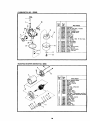
CARBURETOR
NO.
I
632420
i
26
/
Ref.
No.
,---
14
/r
\
I
3
I1
15
Part
No.
1
3
4
5
6
7
9
11
12
632420
631615
631616
650506
631767
631971
631184
632047
631027
631021
13
631022
15
16
21
22
14
631024
631700
631334
632421
632019
I
t
16
r
_..',-_
21
2566 631028
631775
27
632158
Part
Name
Carburetor
Shaft _ Lever Assy., Throttle
Shutter, Throttle
Screw, Throttle shutter
Spring, Throttle return
Seal, Dust
Washer, Flat
Primer Assy.
Plug, Welch
Inlet Needle, Seat Et Clip Assy.
(incl. No. 13)
Clip, Inlet needle
Float, Carburetor
Shaft, Float
Bowl, Float
Gasket, Bowl-to-body
Nut, Float bowl
Gasket, Bowl-to-body
Fitting, Fuel inlet
Spacer
t
.-22
ELECTRIC STARTER
iml
MOTOR NO. 34934
[ II
I
12
11
12
Ref,
NO.
1
2
3
4
5
6
7
8
10
11
12
13
14
15
16
17
18
""
I
i
28
Part
No.
34934
34955
3495O
34954
34949
34943
33450
34944
34945
59050O
34942
Part Name
Motor, Electric Starter
Ring, Retainer
Retainer, Spring
Spring
Gear
Cap Assy., Drive end
Nut, Lock
Armature
Housing Assy.
Washer, Thrust
Cap Assy., Commutator end (Incl.
brushes,which cannot be serviced
separately)
34947 Bolt, 10-32 x 3-3/16
34946 Dr'rver,Pinion
34951 Washer, Cup
34952 Ring, Retainer
34948 Washer
34953 Nut, Drive
5906O8 Washer, Dust
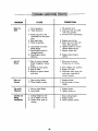
i TROUBLE SHOOTING
PROBLEM
Does not
Start
CORRECTION
CAUSE
I. Out of gasoline.
2. "Stale Gasoline."
3. Spark plug wire is disconnected from the spark
plug.
4. Bad spark plug.
5. Water in gasoline.
6. Loose blade or broken
blade flange.
7. Zone/Engine control in
released position.
8. Zone/Engine control
defective.
Loss of
Power
i
1. Fill gasoline tank.
2. Drain gas tank and refill
with fresh gasoline.
3. Connect wire to spark plug.
4. RepJace spark plug.
5. Drain tank and refill with
fresh, clean gasoline.
6. Tighten b_ade nut and/or
replace blade flange.
7. Depress control bar.
8. Replace Zone/Engine
control.
1. Rear of mower housing/
blade dragging in heavy
grass.
2. Cutting too much grass.
3. Dirty air filter.
4. Build-up of grass, leaves,
and trash.
r
Poor cutUneven
POINTS
1
Raise rear of mower
housing one (1) setting.
.
Set in "Higher Cut" position.
3. Replace air filter.
4. Disconnect spark plug wire,
and clean underside of
mower housing.
,.1..
1 f
1. Worn or bent blade.
i
1. Replace blade.
2. Set all wheels at same
2. Wheel heights uneven.
height.
Too much
Vibration
1. Worn or bent blade.
2. Loose blade.
1. Replace blade.
2. Tighten blade nut.
Catcher not
1. Cutting height too low.
2. Lift on blade worn off.
1. Raise cutting height.
2. Replace blade.
3. Clean/replace catcher.
Filling
Completely
3. Catcher dirty, poor air
venting.
2g
LAWN
NOTE:
Change
Engine
Oil
offer
the
MOWER
first two
CARE RECORD
(2) hours
of use, and
then
every
25
hours
DATE
DATE
DATE
J
Changed Oil: 10W30
or SAE 30
Replaced spark plug:
Replaced
air filter:
Replaced
blade:
.
m
i
i
Tuned-up:
i
i
..
i
i
i i
iii
i
i
i. 11
iii,
ii ,1_
i
ii
iiiii
iiii
i
.
3O
of use.
LAWN
MOWER
CARE RECORD
NOTE: Chonge Engine Oil offer the first two (2) hours of use, and then every 25 hours o| use.
DATE
DATE
ii
Changed Oil: I0W30
or SAE 30
Replaced spark plug:
Replaced air filter:
Replaced blade:
i
i
Tuned-up:
1
SERVICE is at
YOUR SERVICE
HOW TO ORDERREPAIRPARTS
Each LAWN MOWER has its own MODEL
Each ENGINE has its own MODEL NUMBER.
NUMBER.
OWNER'S
MANUAL
The MODEL NUMBER for the lawn mower wilt be found on a
plate attached to your lawn mower at the REAR OF THE
HOUSING.
The MODEL NUMBER for the lawn mower will be found on a e
plate attached to your lawn mower at the REAROF THE_.
HOUSING.
Always mention these MODEL NUMBERS when requesting
service or repair parts for your LAWN MOWER.
MODEL
NO.
91 7.374400
All parts listed herein may be ordered through SEARS,
ROEBUCK AND CO. SERVICE CENTERS and most Retail
Stores.
If parts you need are not stocked locally your order will
be electronically transmitted to a SEARS PARTS DISTRIBUTION CENTER for expedited handling.
WHEN ORDERING REPAIR PARTS, ALWAYS
FOLLOWING INFORMATION:
Serial .....
Number
Model and Serial Number
1. The PART NUMBER
2. The PART DESCRIPTION
may be found on the
number plate on the rear of
the mower housing.
3. The MODEL NUMBER - 917.374400
4. The NAME OF THE PRODUCT - CRAFTSMAN
POWER-PROPELLED lAWN MOWER
5. The ENGINE MODEL NUMBER - 143.364052
You should record both
Model and Serial Number
and keep in a safe place
for future reference.
Part No. 86422
I
Rev. I
12/i
9/85
22"
Your Sears merchandise has added value when you consider
that Sears has service units nationwide staffed with Sears
trained
technicians...professional
technicians
specifically
trained on Sears products, having the parts, tools and the
equipment to insure that we meet our pledge to you, we
service what we sell.
SOLD BY SEARS, ROEBUCK AND
.......
GIVE THE
CO.,
CHICAGO,
I
[ml
I
IL 60684
1111111
I
U.S.A.
I
Printed in U.S.A,