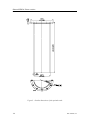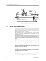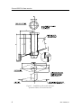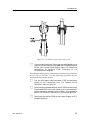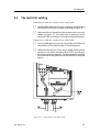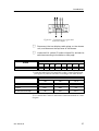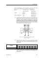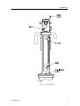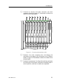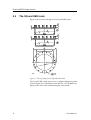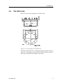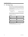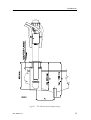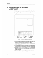
1
Installation manual Simrad SD570 Fishery sonar www.simrad.com ALWAY S AT THE FOR EFR ONT OF TECHNOLOG Y Simrad SD570 Fishery sonar Installation manual 851--160085 / Rev.B Note Simrad AS makes every effort to ensure that the information contained within this document is correct. However, our equipment is continuously being improved and updated, so we cannot assume liability for any errors which may occur. Warning The equipment to which this manual applies must only be used for the purpose for which it was designed. Improper use or maintenance may cause damage to the equipment or injury to personnel. The user must be familiar with the contents of the appropriate manuals before attempting to operate or work on the equipment. Simrad AS disclaims any responsibility for damage or injury caused by improper installation, use or maintenance of the equipment. Copyright E 2004 Simrad AS ISBN 82-8066-018-6 The information contained within this document remains the sole property of Simrad AS. No part of this document may be copied or reproduced in any form or by any means, and the information contained within is not to be communicated to a third party, without the prior written consent of Simrad AS. Support For support on your Simrad equipment, consult your local dealer, visit www.simrad.com, or contact us directly at support.fish@simrad.com. Simrad AS Strandpromenaden 50 Box 111 N-3191 Horten Telephone: Facsimile: +47 33 03 40 00 +47 33 04 29 87 M A X I M I Z I N G Y O U R P E R F O R M A N C E A T S E A Installation manual Sections This book is the Installation manual for the SD570 fishery sonar. It describes how to install the various units used by the SD570 system. 1 Introduction This section gives a brief description of the SD 570/SE 570 sonars and the installation requirements. 2 Installation procedures This section provides the necessary information for the installation and cabling of the complete sonar system according to Simrad’s requirements. 3 Start-up procedures This sectioncontains the start-up procedures to be carried out after the installation of the sonar. 4 Trunk systems This section describes the different trunk systems that can be used with the SD 570/SE570 Hull Unit. Also described are the adapter flanges which must be used if the Hull Unit is to be installed into already installed SQ4, SQ, SB2 and SK3 trunks. 5 Drawings 6 Appendices 851-160085 / B 1 Simrad SD570 Remarks References Further information about the SD570 system may be found in the following manuals: • SD570 Operator manual The reader This Installation manual is intended for the design and installation engineers at the shipyard performing the installation. The information is supplied as the basis for the shipyard’s own installation drawings applicable to the vessel. On completion of the installation, this manual must be kept on the vessel for reference purposes during system maintenance. Note This manual includes sections that may be revised individually. In the event of a revision to any part of this manual, this “Cover and Contents” section will be replaced. 2 851-160085 / B Installation manual Document revisions Rev Checked by Written by Date Sign A Unknown CL B 02.02.04 RBr Sect Title Approved by Date Sign Date Sign 02.02.04 EGj 02.02.04 ESB Revision File 0 Cover and contents B 851--160085 1 Introduction B 851--160115 2 Installation procedures B 851--160116 3 Start--up procedures B 851--160117 4 Trunk system B 851--160503 5 Drawings B 851--160118 6 Appendices B 851--160675 Rev.A First edition. Rev.B Re--issued. All sections updated to Rev.B, but product specific information has not been changed. ISBN number issued. 851-160085 / B 3 Simrad SD570 Blank page 4 851-160085 / B Installation manual High voltage safety warning Precautionary measures The voltages used to power this equipment are potentially lethal. Even 110 volts can kill. Whenever possible, the following precautionary measures must be taken before any work is carried out inside the equipment: S Switch off all high-voltage power supplies. S Check the operation of any door interlocks and any other safety devices. S Completely discharge all high-voltage capacitors. It should be noted that interlocks and safety devices are normally located only at regular access points, and high voltages may be exposed during dismantling. Never work alone on high-voltage equipment! First aid in the event of electric shock Normally, even a high voltage electric shock will not kill instantly. The victim can still be revived even when his breathing and heart-beat have ceased. Could YOU save someone’s life? In the event of electric shock, the correct actions, performed quickly may well save the victim’s life. Make sure you know what to do! 2 Open his mouth and check for and remove any false teeth, chewing gum etc. 3 Check if the victim is breathing. If not, check if his heart is beating. The pulse is normally easily found in the main arteries of the neck, either side of the throat, up under the chin. If his heart is beating but he is not breathing, commence artificial respiration. If the victim’s heart is not beating, commence external cardiac massage (ECM). Continue to shout for assistance till someone arrives. External cardiac massage 1 Kneel beside the victim. Place the heel of one hand in the centre of his chest, at a position half way between the notch between the collar-bones at the top of his chest, and the dip in the breast-bone at the base of his rib cage. Place the other hand on top of the first. 2 Keeping the arms straight and using your entire weight, press down rapidly so that the breast bone is depressed four- five cm, then release the pressure. Repeat rhythmically at a rate of one cycle per second. This will be hard work, but keep going. His life depends on YOU. Do not worry about breaking his ribs - these will heal if he survives. Immediate action While shouting for help, remove the source of power from the victim. Switch off the supply if possible, or using a dry, non-conductive material (rubber gloves, broom handle etc.) to insulate yourself, separate the victim from the source. If the voltage exceeds 1000 volts, switch off the supply and be ready to catch the victim. Take care- do not become a victim yourself. Commence first aid on the spot. Continue to shout for assistance till someone arrives. 1 Lay the victim flat on his back and loosen any tight clothing (collar, tie, belt etc.). 851-160085 / B I Simrad SD570 Artificial respiration 1 Kneel besides the victim’s head. Place one hand under his neck and lift, allowing his head to fall back. This will lift his tongue and open the air passage in his throat. 2 Place the palm of the hand on his forehead to maintain the ”chin-up” position. 3 Using the index finger and thumb of the same hand, pinch the victim’s nostrils closed. Open his mouth. 4 Take a deep breath and cover his mouth with yours. Blow steadily into his lungs to expand his chest. Remove your mouth from his to allow the air to escape from his chest. You should be able to see his chest deflate. 5 Repeat the ”inflation-deflation” cycle at a rate of about 12 cycles per minute till the victim begins to breath normally again. Remove the victim to a hospital as soon as possible, but do not interrupt the artificial respiration and ECM cycles till his heart beat and breathing returns. If started quickly and performed correctly, the resuscitation methods described will keep a sufficient volume of oxygenated blood flowing trough the victims body to allow full recovery. Proficiency in the resuscitation methods can only be achieved trough training. All personnel concerned should attend courses on a regular basis. Remember, someone’s life could depend on you. Do you know what to do? Combining ECM and artificial respiration If you are alone, perform one cycle of artificial respiration for every five cycles of ECM. This will be hard work, but keep going. His life depends on you! If there are other people available to help, one should perform the ECM while one performs the artificial respiration for every five cycles of ECM. It will be much more efficient with two people. Once the victim’s heart is beating and he is breathing, roll him onto his side and support him in that position. As consciousness returns he may vomit, and this will allow any liquid to drain out of his mouth. II 851-160085 / B Introduction 851- 160115 / AA000 / 3- 11 Introduction This section gives a brief description of the SD 570 / SE 570 sonars and the installation requirements. 851--160115 / B I Simrad SD570 / Base version Document revisions Rev Date A Unknown B 03.01.01 Written by Checked by Approved by RBr ESB RBr C D (The original signatures are recorded in the company’s logistic database) II 851--160115 / B Introduction Table of contents 1 INSTALLATION DOCUMENT . . . . . . . . . . . . . . . . . . . . . . . . . . . . . . . . . . 1 2 SUPPLY CONDITIONS . . . . . . . . . . . . . . . . . . . . . . . . . . . . . . . . . . . . . . . 2 2.1 2.2 General . . . . . . . . . . . . . . . . . . . . . . . . . . . . . . . . . . . . . . . . . . . . . . . . . . . . . Main units . . . . . . . . . . . . . . . . . . . . . . . . . . . . . . . . . . . . . . . . . . . . . . . . . . 2 2 2.3 Options . . . . . . . . . . . . . . . . . . . . . . . . . . . . . . . . . . . . . . . . . . . . . . . . . . . . . 2 2.4 2.5 Installation procedures . . . . . . . . . . . . . . . . . . . . . . . . . . . . . . . . . . . . . . . Equipment responsibility . . . . . . . . . . . . . . . . . . . . . . . . . . . . . . . . . . . . . 5 5 2.6 Receipt, unpacking and storage . . . . . . . . . . . . . . . . . . . . . . . . . . . . . . . . 5 3 GENERAL REQUIREMENTS . . . . . . . . . . . . . . . . . . . . . . . . . . . . . . . . . . 7 3.1 3.2 Responsibility and approbation . . . . . . . . . . . . . . . . . . . . . . . . . . . . . . . . Compass deviation . . . . . . . . . . . . . . . . . . . . . . . . . . . . . . . . . . . . . . . . . . . 7 7 3.3 Noise sources . . . . . . . . . . . . . . . . . . . . . . . . . . . . . . . . . . . . . . . . . . . . . . . 7 3.4 3.5 3.6 Docking . . . . . . . . . . . . . . . . . . . . . . . . . . . . . . . . . . . . . . . . . . . . . . . . . . . . Cabling . . . . . . . . . . . . . . . . . . . . . . . . . . . . . . . . . . . . . . . . . . . . . . . . . . . . . Auxiliary equipment . . . . . . . . . . . . . . . . . . . . . . . . . . . . . . . . . . . . . . . . . 7 7 8 3.7 3.8 Technical specifications . . . . . . . . . . . . . . . . . . . . . . . . . . . . . . . . . . . . . . . Weights and dimensions . . . . . . . . . . . . . . . . . . . . . . . . . . . . . . . . . . . . . . 9 10 851--160115 / B III Simrad SD570 / Base version Document history (The information on this page is for internal use) Rev.A Original issue for Base version. Rev.B Document transferred to Interleaf. No changes made to text or illustrations. IV 851--160115 / B Introduction 1 INSTALLATION DOCUMENT This installation manual will act as an installation document for later updating and service on the sonar, and must therefore be stored on board the vessel into which the equipment is to be installed. To ensure the best possible result of the installation, it is important that each procedure is carefully followed. Each listed procedure comprises squares for ticking off while proceeding in the procedure. In addition to be a sign that the procedure is followed, this will also be a good guidance for the installer. Note that the installer becomes fully responsible for the equipment during the installation, and that the guarantee only is covered when the installation is made in full accordance with this installation manual. 851--160115 / B 1 Simrad SD570 / Base version 2 2.1 SUPPLY CONDITIONS General This manual describes the installation for both the SD 570 and the SE 570 sonars. The only difference between these sonars is the angle to which the transducer can be tilted. The SD 570 transducer can be tilted to - 90_, while the SE 570 transducer is limited to - 45_. All units for the SD 570 and SE 570 have the same physical size. The Hull Unit uses an installation trunk which is equal to the old Simrad SL and SX installation trunks. The Hull Unit can therefore easily be mounted in an old SL or SX trunk. As an option, an adapter flange can be delivered for mounting the Hull Unit in an old SK, SB or SQ trunk. Note that the trunk is not included in the standard delivery, but can be ordered as an option (see chapter 2.3 Options ). 2.2 Main units The standard SD 570 Sonar system comprises the following main units: Simrad SD 570 Sonar Control Unit . . . . . . . . . . . . . . SD5- 112629 Simrad SD 570 Transceiver Unit . . . . . . . . . . . . . . . . SD5- 112630 Simrad SD 570 Hull Unit . . . . . . . . . . . . . . . . . . . . . . . SD5- 112631 The standard SE 570 Sonar system comprises the following main units: Simrad SE 570 Sonar Control Unit . . . . . . . . . . . . . . . SE5- 112898 Simrad SE 570 Transceiver Unit . . . . . . . . . . . . . . . . . SE5- 112899 Simrad SE 570 Hull Unit . . . . . . . . . . . . . . . . . . . . . . . SE5- 112900 A diagram of the standard sonar system is shown in figure 1. 2.3 Options The installation trunk can be made by the shipyard (refer to drawing in section “Trunk systems” ) or be ordered as an optional delivery: Installation trunk with blind cover . . . . . . . . . . . . . . SD5- 112632 For installations in an existing SK, SB or SQ trunk, refer to the drawings in the section Trunk systems in this manual. The following adapters with blind covers can be ordered as options: SQ4 Adapter flange . . . . . . . . . . . . . . . . . . . . . . . . . . . SD5- 112641 2 851--160115 / B Introduction SQ & SB2 Adapter flange . . . . . . . . . . . . . . . . . . . . . . SD5- 112642 SK3 Adapter flange . . . . . . . . . . . . . . . . . . . . . . . . . . . SD5- 112643 The cable between the Sonar Control Unit in the wheelhouse and the Transceiver Unit in the sonar room (see figure 1) can be delivered with the following lengths: 50- meter interconnection cable . . . . . . . . . . . . . . . . . . 380- 112595 75- meter interconnection cable . . . . . . . . . . . . . . . . . . 380- 112596 100- meter interconnection cable . . . . . . . . . . . . . . . . . 380- 112597 The interconnection cable has a preconnected connector at the Sonar Control Unit end. A system for electronic stabilization of the transducer may be delivered as an option. If the stabilization system is ordered, the kit is included in the box for the Sonar Control Unit. Stabilization system . . . . . . . . . . . . . . . . . . . . . . . . . . . KIT- 113200 851--160115 / B 3 Simrad SD570 / Base version Figure 1 - SD 570 / SE 570 sonar system 4 851--160115 / B Introduction 2.4 Installation procedures The installation of the standard SD 570 / SE 570 Sonar systems includes the following stages: The installation of the standard SP 270 Sonar system includes the following stages: • Mounting the Installation Trunk • Mounting the Hull Unit • Mounting the Transceiver Unit • Mounting the Sonar Control Unit • Cabling • Start- Up • Final Test Refer to the cable plan, the main interconnection diagrams and the outline dimensions drawings of the units. 2.5 Equipment responsibility Upon receipt of the equipment, the installation shipyard and/or the dealer automatically becomes fully responsible for the equipment unless otherwise is stated in the contract. This responsibility covers the storage period before the installation, the actual installation, commissioning, and the period between the commissioning and the acceptance of the equipment by the end user (normally the owner of the vessel into which the equipment is to be installed). The guarantee period for the system (as specified in the contract) begins as soon as acceptance documents have been signed, unless other arrangements have been made in the contract. 2.6 Receipt, unpacking and storage On receiving the equipment, the shipyard and/or the dealer should ensure that the delivery is complete and inspect each container for physical damage. If the inspection at receipt reveals indication of crushing, dropping, immersion in water or any other form of damage, the recipient should request a representative from the carrier to be present during unpacking. During unpacking, the equipment should be inspected for physical damage, i.e. broken controls and indicators, dents, scratches etc. If damage to the equipment is discovered, the recipient should notify the carrier and Simrad so that Simrad can arrange for replacement or repair of the damaged equipment. 851--160115 / B 5 Simrad SD570 / Base version The equipment, once unpacked, must be stored inside in a room with an atmosphere free from corrosive agents. In addition, the equipment must be covered to protect it from dust and other forms of contamination. 6 851--160115 / B Introduction 3 3.1 GENERAL REQUIREMENTS Responsibility and approbation The Hull Unit of the sonar is generally approved by The Norwegian Veritas (Organization for classification and registry of shipping). An approval of the installation must, however, be applied for in each case to the local maritime authority. The ship owner and the shipyard are responsible for the application. 3.2 Compass deviation When the installation is finished, the compass must be checked both with the sonar operative and inoperative. The ship owner and the skipper are responsible for such a check to be carried out. 3.3 Noise sources Prior to installation, the vessel’s hull should be thoroughly inspected in dock. Roughness on the shell plating surface, and protruding obstacles are examples of noise- causing elements. These must be smoothed or removed. Also ensure that the propeller is not chipped or corroded. 3.4 Docking When dry docking the vessel, make sure that there is enough room underneath for installation of the sonar trunk and protection blister (refer to figures 4 and 5 in section Installation procedures . 3.5 Cabling If the cable from the wheelhouse to the sonar room passes through hatches or places where it may be damaged, it should be run through a pipe. Note that the cable must not be installed together with high- power cables, antenna cables etc. 851--160115 / B 7 Simrad SD570 / Base version 3.6 Auxiliary equipment The SD 570/SE 570 sonars require connection of a speed log and a course gyro. An inaccurate log or gyro input will cause inaccurate indication of the vessel and target movements. Speed log: • Pulse log: 100, 200 or 400 pulses/nm. • Serial line, standard NMEA 0183; RS232, RS422 or Current loop. Course gyro: • 3- phase synchro signal, 20- 220V L- L, 50/60/400 Hz. Gear ratio 1:360, 1:180, 1:90, 1:36 • 3- phase stepper signal, 20- 220V L- L. Gear ratio 1:360, 1:180, 1:90, 1:36. • Serial line, standard NMEA 0183; RS232, RS422 or Current loop. Echo sounder: In order to get a depth indication on the catch control page on the sonar, one of the following Simrad echo sounders can be connected: • EQ50, EQ55, EQ100, ES60, ES380 series, ES500 (RS232 serial line). Trawl system: In order to get the trawl information on the sonar display, one of the following Simrad trawl systems can be connected: • FS 903 Trawl sonar system (RS232 serial line) • FS 3300 Trawl sonar (RS232 serial line or 20 mA current loop) • ITI Integrated trawl instrumentation (RS232 serial line) 8 851--160115 / B Introduction 3.7 Technical specifications Table 1 comprises the specifications required for the installation. For further details, refer to the Operator Manual. Sonar Control Unit Transceiver Unit Hull Unit Voltage, nominal 115/230VAC Single phase* 115/230 VAC Single phase** 230/380/440 VAC 3--phase*** Voltage deviation ±15% of nominal ±15% of nominal 230V:±15% 380/440V: 340 -- 485V Voltage transient ±20% of nominal recovery time 3s ±20% of nominal recovery time 3s ±20% of nominal recovery time 3s Power consumption 100 VA 500 VA 600 VA max. Frequency 47 -- 63 Hz 47 -- 63 Hz 47 -- 63 Hz Temp.: Storage Operating --40 to +70°C 0 to +40°C --40 to +70°C 0 to +40°C --20 to +70°C 0 to +40°C Humidity 5--95% relative non--condensing 5--95% relative non--condensing 5--96% relative non--condensing Table 1 Technical specifications for the SD 570 / SE 570 sonars Refer to the voltage, nominal line in table 1. 851--160115 / B * Input voltage is automatically selected. ** Input voltage is selected with two switches. *** Input voltage is selected on the motor connections 9 Simrad SD570 / Base version 3.8 Weights and dimensions Weight SD 570 Weight SE 570 Dimensions Sonar Control Unit 28 kg 28 kg See figure 2 Transceiver Unit 75 kg 70 kg See figure 3 Hull Unit 275 kg 265 kg See figure 4 Trunk (optional) 68 kg 68 kg See figure 5 Table 2 Weights of the SD 570 and SE 570 sonars SP 270 sonar The figures 2, 3, 4 and 5 show the outline dimensions of the SD 570 / SE 570 units. 10 851--160115 / B Introduction Figure 2 - Outline dimensions of the Sonar Control Unit 851--160115 / B 11 Simrad SD570 / Base version Figure 3 - Outline dimensions of the Transceiver Unit 12 851--160115 / B Introduction Figure 4 - Outline dimensions of the Hull Unit 851--160115 / B 13 Simrad SD570 / Base version Figure 5 - Outline dimensions of the optional trunk 14 851--160115 / B Introduction 851- 160116 / AA000 / 3- 11 Installation procedures This section provides the necessary information for the installation and cabling of the complete SD 570/ SE 570 sonar systems according to Simrad’s requirements. 851--160116 / B I Simrad SD570 / Base version Document revisions Rev Date A Unknown B 03.01.01 Written by Checked by Approved by RBr ESB RBr C D (The original signatures are recorded in the company’s logistic database) II 851--160116 / B Introduction Table of contents 1 2 3 INSTALLATION PLANNING . . . . . . . . . . . . . . . . . . . . . . . . . . . . . . . . . . . 1 1.1 1.2 1.3 1 1 2 General . . . . . . . . . . . . . . . . . . . . . . . . . . . . . . . . . . . . . . . . . . . . . . . . . . . . . Location of the Hull Unit . . . . . . . . . . . . . . . . . . . . . . . . . . . . . . . . . . . . . . Sonar room requirements . . . . . . . . . . . . . . . . . . . . . . . . . . . . . . . . . . . . . INSTALLATION OF THE SONAR TRUNK . . . . . . . . . . . . . . . . . . . . . . . 5 2.1 2.2 2.3 2.4 5 6 6 6 Mounting of the trunk . . . . . . . . . . . . . . . . . . . . . . . . . . . . . . . . . . . . . . . . Protecting blister . . . . . . . . . . . . . . . . . . . . . . . . . . . . . . . . . . . . . . . . . . . . . Corrosion protection . . . . . . . . . . . . . . . . . . . . . . . . . . . . . . . . . . . . . . . . . Trunk installation measurements . . . . . . . . . . . . . . . . . . . . . . . . . . . . . . . INSTALLATION OF THE HULL UNIT . . . . . . . . . . . . . . . . . . . . . . . . . . . 9 3.1 3.2 3.3 3.4 Unpacking the Hull Unit . . . . . . . . . . . . . . . . . . . . . . . . . . . . . . . . . . . . . . Mounting the Hull Unit . . . . . . . . . . . . . . . . . . . . . . . . . . . . . . . . . . . . . . . Staying . . . . . . . . . . . . . . . . . . . . . . . . . . . . . . . . . . . . . . . . . . . . . . . . . . . . . Alignment of the transducer . . . . . . . . . . . . . . . . . . . . . . . . . . . . . . . . . . . 9 10 11 11 3.5 Installation checklist . . . . . . . . . . . . . . . . . . . . . . . . . . . . . . . . . . . . . . . . . . 12 4 INSTALLATION OF THE TRANSCEIVER UNIT . . . . . . . . . . . . . . . . . . 13 5 INSTALLATION OF THE SONAR CONTROL UNIT . . . . . . . . . . . . . . 16 5.1 5.2 Location of the Sonar Control Unit . . . . . . . . . . . . . . . . . . . . . . . . . . . . . Mounting of the Sonar Control Unit . . . . . . . . . . . . . . . . . . . . . . . . . . . . 16 17 Desk top mounting . . . . . . . . . . . . . . . . . . . . . . . . . . . . . . . . . . . . . Panel mounting . . . . . . . . . . . . . . . . . . . . . . . . . . . . . . . . . . . . . . . . Bulkhead mounting . . . . . . . . . . . . . . . . . . . . . . . . . . . . . . . . . . . . 17 18 18 6 7 CABLING . . . . . . . . . . . . . . . . . . . . . . . . . . . . . . . . . . . . . . . . . . . . . . . . . . . 20 6.1 Cable plan . . . . . . . . . . . . . . . . . . . . . . . . . . . . . . . . . . . . . . . . . . . . . . . . . . 20 6.2 The Sonar Control Unit cabling . . . . . . . . . . . . . . . . . . . . . . . . . . . . . . . . 22 6.3 6.4 The Transceiver Unit cabling . . . . . . . . . . . . . . . . . . . . . . . . . . . . . . . . . . The Hull Unit cabling . . . . . . . . . . . . . . . . . . . . . . . . . . . . . . . . . . . . . . . . 24 27 CONNECTING AUXILIARY EQUIPMENT . . . . . . . . . . . . . . . . . . . . . . . 28 7.1 7.2 General . . . . . . . . . . . . . . . . . . . . . . . . . . . . . . . . . . . . . . . . . . . . . . . . . . . . . Connecting the course gyro . . . . . . . . . . . . . . . . . . . . . . . . . . . . . . . . . . . Connecting a course gyro with synchro output . . . . . . . . . . . . 28 29 29 Connecting a course gyro with stepper output . . . . . . . . . . . . . 33 Connecting a course gyro with serial line output . . . . . . . . . . 36 Connecting the speed log . . . . . . . . . . . . . . . . . . . . . . . . . . . . . . . . . . . . . Connecting the pulse log . . . . . . . . . . . . . . . . . . . . . . . . . . . . . . . . 39 39 7.3 851--160116 / B III Simrad SD570 / Base version 7.4 7.5 IV Connecting a speed log with serial line output . . . . . . . . . . . . Connecting other auxiliary equipment . . . . . . . . . . . . . . . . . . . . . . . . . . Remounting the electronic drawer unit . . . . . . . . . . . . . . . . . . . . . . . . . 40 42 42 851--160116 / B Introduction Document history (The information on this page is for internal use) Rev.A Original issue for Base version. Rev.B Document transferred to Interleaf. No changes made to the text or illustrations. 851--160116 / B V Simrad SD570 / Base version Blank page VI 851--160116 / B Introduction 1 INSTALLATION PLANNING Note ! For installation in an already installed trunk system, first read through chapter 1.3 about the sonar room requirements. Then, for an already installed SL or SX trunk system, continue to procedure 3 Installation of the Hull Unit . For installation in an already installed SK, SB or SQ trunk system, refer to section Trunk systems in this manual. 1.1 General This chapter provides the necessary information for the ship designer to plan and carry out the installation of the SD 570/SE 570 hull system according to Simrad’s requirements. Study this chapter thoroughly to achieve the recommended knowledge of the procedures. Note that individual installation drawings must be designed by the shipyard, and the construction must be approved by the classification authorities at the customer’s expense. Simrad offers free advice for installation planning. The proposal for the arrangement may be sent to Simrad for comments, or may be worked out by Simrad. If such assistance is required, the following drawings should be submitted: · General arrangement · Body plan and drawings of bottom tanks and cofferdam · Sheer drawing 1.2 Location of the Hull Unit The Hull Unit should preferably be located within 1/10 to 1/3 of the ship’s length between perpendiculars (LBP), measured from the fore perpendicular (FP). Refer to figure 1. Larger deviations from this rule should not be made without consulting Simrad. The Hull Unit may be located symmetrically on the centre line of the vessel, or alongside the keel. When determining the exact location, make sure that the transducer will have free view under the keel (refer to figure 1). The Hull Unit trunk must be installed such that it will be vertical under normal operating conditions. Water inlets and protruding details which create turbulence, should not be located in front of the transducer. For the same reason, check that the shell plating in front of the trunk is not damaged. 851--160116 / B 1 Simrad SD570 / Base version Figure 1 - Location of the Hull Unit 1.3 Sonar room requirements The sonar room should be dimensioned to house the Hull Unit and the Transceiver Unit. This because the length of the flexi- hose protected cabling from the Hull Unit to the Transceiver Unit is limited to approximately 3.5 meters. By installing the units in a well designed sonar room, the risk of corrosion is reduced, the maintenance is simplified, and the reliability is increased. A suggested arrangement of the sonar room is shown in figure 2. The free space should not be obstructed by girders or pipes etc., which might cause problems for the installation and maintenance work. Access hatches The sonar room must be accessible under all conditions, and the doors or hatches should be so designed that the installed units can be removed without being disassembled. A tackle carrier designed for a load of a minimum of 2 tons should be mounted above the Hull Unit. The tackle may be used to facilitate the mounting of the trunk and Hull Unit, and is also intended for use in future service of the Hull Unit. Heating The sonar room should be furnished with a heating element of 1000 W, mounted close to the floor. Insulation The bulkhead must be insulated and plated down to the floor. The insulation should equal a minimum of 50 mm of rock- wool. 2 851--160116 / B Introduction Ventilation The sonar room should preferably be connected to the ship’s ventilation system. If this is not possible, two 3- inch vent pipes must be laid from the sonar room to free air on deck. The air inlet should be close to the floor, while the outlet should be placed as high as possible. Funnels should be mounted below the vent pipes to collect condensed water. To ensure the best possible ventilation, the outlet pipe should run at least 4 meters higher than the inlet pipe. To keep rain and water splash out, the pipes should be fitted with goosenecks or cowls. Cable pipes If the cable between the wheelhouse and the sonar room passes through hatches or places where it can be damaged, it should be run through pipes (2” pipes are recommended). Bilge pump The sonar room should be connected to the ship’s main bilge pump system. If this is not possible, a separate bilge pump for the sonar room must be installed. Lighting To simplify the installation and future maintenance, the sonar room should be equipped with suitable lighting. Docking Make sure that there is ample space below the keel for mounting the hull system, when docking the vessel. To facilitate future docking, mark the position of the trunk as indicated in figure 1 Flooring When the installation is completed, the sonar room should be suitably floored. 851--160116 / B 3 Simrad SD570 / Base version Figure 2 - Example of sonar room arrangement, seen from the bow 4 851--160116 / B Introduction 2 INSTALLATION OF THE SONAR TRUNK 2.1 Mounting of the trunk The location of the sonar trunk has to be carefully selected, as described in chapter 1.2. Refer also to figures 4 and 5. Note the orientation of the centre line of the trunk with regard to the mounting bolts, shown in figure 3. Note ! Remove the gasket on the top flange during the welding. Figure 3 - Orientation of the sonar trunk The height from the top of the trunk flange to the underside of the protection blister must be minimum 920 mm (36 1/4”) as shown in figures 4 and 5. The top flange must be parallel to the construction loadline in the fore- and- aft as well as the athwartships direction. The installation trunk must be welded to an inserted plate which should be 1.5 times as thick as the original shell plate. The size may be determined by the shipyard or the responsible maritime authorities. The trunk must be stiffened to the inserted plate by welding knee- plates on the trunk in both fore- and- aft and athwartships directions. 851--160116 / B 5 Simrad SD570 / Base version 2.2 Protecting blister As illustrated in figures 4 and 5, a steel blister must be fitted for protection. The blister shown in figure 4 is welded to the shell plating and then filled with oil to prevent corrosion. This method provides excellent protection and simplifies maintenance. The blister shown in figure 5 is of the open type, to be welded to the shell plating. 2.3 Corrosion protection As soon as the trunk is mounted, and welding and grinding are finished, the trunk should be painted with a quality protective paint. 2.4 Trunk installation measurements For future use, the measurements of the distance A, and the heights B and C shown in figures 4 and 5 have to be carried out and put into the table on the next page. mm inches Distance A Height B Height C In case of an other installation solution, make a scheme with dimensions below. 6 851--160116 / B Introduction Figure 4 - Installation of trunk with extension and oil- filled blister 851--160116 / B 7 Simrad SD570 / Base version Figure 5 - Installation of the trunk with open protection blister. No trunk extension. 8 851--160116 / B Introduction 3 3.1 INSTALLATION OF THE HULL UNIT Unpacking the Hull Unit In order to prevent damage of the transducer and the transducer cables while handling the Hull Unit, these parts are especially protected. This means that both the transducer protection and the cable protection should still be mounted to the Hull Unit when it is being lowered down into the sonar room (see figure 6). Figure 6 - Lifting the Hull Unit 851--160116 / B 9 Simrad SD570 / Base version j 3.2 When unpacking the Hull Unit, first remove the top cover from the wooden box, then pull out the nails marked with Indian ink. Fasten the lifting device to the two lifting eye bolts on the top of the gallows and lift the Hull Unit with the protections carefully out from the transport box. Mounting the Hull Unit The Hull Unit should normally be oriented with the hoisting/lowering motor pointing aft (see figure 7). If this orientation makes the motor control unit on the Hull Unit difficult to access, the Hull Unit may be oriented in the most suitable position. Note ! The motor control unit should never be dismounted from the Hull Unit (see text above). j Use a tackle to lower the Hull Unit with the protections down into the sonar room (see figure 6). Remove the blind cover from the trunk, and check that the gasket is not damaged. Store the blind cover in the sonar room for possible future use. Figure 7 - Recommended orientation of the Hull Unit j 10 Remove the transport protection from the transducer and lower the Hull Unit carefully down into the trunk. Tighten the flange nuts with a torque of approximately 6 kpm. 851--160116 / B Introduction j 3.3 Remove the cable protection box. The transducer cables and connectors have to be kept dry and handled with care to avoid mechanical damage. Staying The Hull Unit is constructed to be in the lower position with a maximum speed of 15 knots. To prevent unwanted vibrations, the Hull Unit has to be stayed off against the bulkhead. Remove the lifting rings on the top of the gallows on the Hull Unit and use the holes for fastening of the staying in the fore- and- aft direction. In case of service on the Hull Unit, it should be possible to remove the staying. 3.4 Alignment of the transducer Note that the transducer should not be mechanically aligned even if the Hull Unit is oriented differently from figure 7. The transducer alignment will be carried out later by turning the echo picture in the computer. 851--160116 / B 11 Simrad SD570 / Base version 3.5 Installation checklist For the following check list, refer to the sonar room requirements in chapter 1.3. INSTALLATION CHECKLIST YES NO Are the access hatches satisfactory? Is the heating satisfactory? Is the insulation satisfactory? Is the ventilation satisfactory? Are the access hatches satisfactory? Is a bilge pump installed? Is the lighting satisfactory? Is the sonar room suitably floored? If the answer to any of the questions is NO, make a note in the installation certificate at the end of section Start- up procedures. 12 851--160116 / B Introduction 4 INSTALLATION OF THE TRANSCEIVER UNIT Note ! The Transceiver Unit must be mounted as a complete unit, i.e. the door should not be opened until the unit is securely fastened to the bulkhead. Before starting the mounting of the Transceiver Unit, note that the distance between the Hull Unit and the Transceiver Unit is limited because of the flexible transducer cables. Also remember to take into consideration the necessary slack for lowering of the transducer. Do not fasten the transducer cables into the Transceiver Unit before mentioned later in the start- up procedure. The Transceiver Unit cabinet requires a minimum free bulkhead space, which is shown in figure 8. 851--160116 / B j Dismount the two mounting brackets which are fastened to the shock absorbers on the Transceiver Unit. An Allen key is located in the plastic bag which is fastened to the upper shock absorber. j Weld the mounting brackets safely to the bulkhead as shown in figure 8. j Use a tackle carrier to lift the Transceiver Unit in position, and bolt it to the mounting brackets with the bolts included in the delivery. These 8 bolts are located in the plastic bag that was fastened to the upper shock absorber. Remember to fasten the grounding cable from the Transceiver Unit to the mounting bracket as shown in figure 9. 13 Simrad SD570 / Base version Figure 8 - Mounting the brackets for the Transceiver Unit 14 851--160116 / B Introduction Figure 9 - Mounting the Transceiver Unit 851--160116 / B 15 Simrad SD570 / Base version 5 5.1 INSTALLATION OF THE SONAR CONTROL UNIT Location of the Sonar Control Unit The Sonar Control Unit may be mounted on a desk top, in a panel, or to the bulkhead. The necessary hardware for desk top and panel mounting of the unit is included in the delivery. It should be noted that the unit weighs approximately 28 kg, and this weight must be considered when deciding how to mount it. In order to secure the best location according to the routines on board, the location of the Sonar Control Unit should be thoroughly discussed with the skipper. Make sure that proper operating and viewing height is provided. Remember to include the ”Compass Safe Distance” when planning the location: · Sonar Control Unit with internal display Standard compass: 1.4 m Steering compass: 0.9 m · Control Unit without display: Standard compass: 1.1 m Steering compass: 0.6 m When mounting the unit, ensure that it is located to allow easy access to the cable connection panel at the rear of the unit. Ensure that the installation area is dry, and free from excessive dust and vibration. 16 851--160116 / B Introduction 5.2 Mounting of the Sonar Control Unit Desk top mounting Refer to figure 10 for minimum space for the desk top mounting of the cabinet. j Dismount the mounting bracket from the Sonar Control Unit by unscrewing the four bolts on the front. An Allen key is located in the spare parts box. j Bolt the mounting bracket securely to the desk top with the four 10x30mm bolts which are located in the spare parts box. j Mount the cabinet on the mounting bracket with the four bolts. Figure 10 - Desk top mounting 851--160116 / B 17 Simrad SD570 / Base version Panel mounting j Dismount the mounting bracket from the Sonar Control Unit by unscrewing the four bolts on the front. An Allen key is located in the spare parts box. j Cut the panel opening to the following size: Width: 345 mm Height: 380 mm j Place the cabinet into the opening to mark the four fastening holes. j Remove the cabinet and drill the four fastening holes in the panel. Metal panel: Drill 5mm holes for threading with M6 tap, or 7mm holes if through- bolts with nuts are preferred. Wooden panel: Drill 9mm holes for the four thread inserts which are located in the spare parts box. Refer to figure 11 for information about mounting the thread inserts. Figure 11 - Mounting the thread inserts j Place the cabinet into the opening and fasten it with the four bolts. Bulkhead mounting To obtain the best operation position of the cabinet, the cabinet should be mounted with a tilt angle of approximately 20 . An optional mounting bracket can be delivered from Simrad. j 18 Dismount the mounting bracket from the Sonar Control Unit by unscrewing the four bolts on the front. An Allen key is located in the spare parts box. 851--160116 / B Introduction 851--160116 / B j Bolt the bulkhead mounting bracket securely to the bulkhead. j Mount the cabinet on the mounting bracket with the four bolts. 19 Simrad SD570 / Base version 6 6.1 CABLING Cable plan Figure 12 shows the cable plan for the SD 570 and SE 570 sonars. The cable numbers also refer to the interconnection diagram, drawing no. 824- 112979. This drawing is located in section Drawings in this manual. The cable specifications are listed in the table below. Note that cable no. 4 is delivered with a standard length of 50 meters, and has a preconnected plug in the Sonar Control Unit (wheelhouse) end. This cable is included in the Sonar Control Unit package. As an option, cable no. 4 can be delivered in lengths of 75 or 100 meters. Note that the length of the flexible transducer cables 7 and 8 is fixed to approximately 3.5 meters. Cable no. Cable type Cable dia (mm) 1 Screened cable, 2x0.5 mm2 6 2 RCOP 5x1 mm2 12 3,5 Mains cable, length 2 m 7 4,6 Data cable 8x(2+1)x0.5 mm2 14 7,8 Flexi--cable, 3.5 m fixed length. Mounted to Hull Unit 62 9 RCCP/750V 4x2.5 mm@ 17 20 851--160116 / B Introduction Figure 12 - Cable plan for the SD 570 / SE 570 sonars 851--160116 / B 21 Simrad SD570 / Base version 6.2 The Sonar Control Unit cabling All the cables to the Sonar Control Unit are to be plug connected to the electronic drawer unit at the rear of the cabinet (see figure 13). The numbers on the figure refer to the cable numbers on the cable plan. Note ! In order to make service on the Sonar Control Unit, the cables must have a slack so the electronic drawer unit can have all the cables connected while it is outside the cabinet. This could be either by pulling it out from the front, or by reconnecting the cables with the drawer at floor level. Note that cable no. 4 (refer to figure 12) is delivered with a standard length of 50 meters, and has a preconnected plug in the Sonar Control Unit (wheelhouse) end. j Pull cable no. 4 from the wheelhouse to the sonar room. Note that the preconnected plug should be connected to the Sonar Control Unit in the wheelhouse. Remember to include the slack for service purpose. j The mains power cable (3) may be connected to a normal mains outlet in the wheelhouse. If the delivered cable does not fit, put on a suitable connector. Note that the mains power to the Sonar Control Unit can be 115 VAC or 230 VAC, and that this unit will automatically sense the voltage. The connection of the speed log (1) and the course gyro (2) will be described in chapter 7. 22 851--160116 / B Introduction Figure 13 - Cable connections to the Sonar Control Unit 851--160116 / B 23 Simrad SD570 / Base version 6.3 The Transceiver Unit cabling The cable numbers on figure 14 and in the following procedures refer to the numbers on the cable plan and the interconnection diagram. Figure 14 - The cable connection in the bottom of the Transceiver Unit 24 j All cable connections to the Transceiver Unit must have a slack to allow the Transceiver Unit to move up to 10 cm because of the flexible shock mounting. j Start the termination with cable no. 6. This because this cable is connected to the lowest row of the terminals on E201. Use the surplus of cable no. 4, or a similar type of cable. Use the cable gland on the left hand side (refer to figure 14) and terminate the main screen of the cable as shown in figure 15. For termination of each cable pair with screen, refer to the interconnection diagram. Use a part of the enclosed cable sleeve on the screen of each cable pair. 851--160116 / B Introduction Figure 15 - Termination of the cable main screen j Continue with cable no. 4 through the cable gland on the right hand side (see figure 14) and make the termination of the main screen according to figure 15. Make the connections to terminal E201 according to the interconnection diagram. Note that the mains power connection to the Transceiver Unit can be 115 VAC or 230 VAC. Use the following procedure for the connection of the mains power: 851--160116 / B j Pull out the mains input connector P201 on the power supply in the Transceiver Unit. For location of the connector, refer to figure 16. j Set the mains voltage selector switch S201 on the Power Supply and S203 on the HV Power Unit to correspond to the correct mains voltage (115V or 230V), and replace the switch lock to secure the switch in the correct position. j Set the service switch S202 on the Power Supply to OFF (middle) position. 25 Simrad SD570 / Base version Figure 16 - The Power Supply and the HV Power Unit 26 j The mains power cable (3) may be connected to a normal mains outlet in the sonar room. If the delivered cable connector does not fit, put on a suitable connector. j Do not mount the flexible transducer cables to the Transceiver Unit. 851--160116 / B Introduction 6.4 The Hull Unit cabling Connection of cable no. 6 in the motor control unit: j Use the cable gland on the right--hand side, and make the termination of the main screen according to figure 15. j Make a slack on the cable inside the motor control unit as shown on figure 17, and make the connections to the terminal E301 according to the interconnection diagram. Connection of cable no. 9 in the motor control unit: j Use the cable gland on the left--hand side, and make the termination of the cable screen in the cable gland. j Make the connections of the three--phase mains power directly to the motor overload switch S303 according to the interconnection diagram. The grounding wire should be connected to the ground terminal beside the overload switch. Figure 17 - Connections to the Hull Unit 851--160116 / B 27 Simrad SD570 / Base version 7 7.1 CONNECTING AUXILIARY EQUIPMENT General It is not necessary to make the connection of the auxiliary equipment before the start- up procedure is finished, and this equipment may therefore be connected later. Anyhow, do not connect the plugs for the auxiliary equipment to the Sonar Control Unit before mentioned in a later chapter. The SD 570 / SE 570 sonars require connection of a speed log and a course gyro. An inaccurate log or gyro input will cause inaccurate indication of the vessel and target movements. Speed log: · Pulse log: 100, 200 or 400 pulses/nm. · Serial line, standard NMEA 0183; RS232, RS422 or Current loop. Course gyro: · 3- phase synchro signal, 20- 220V L- L, 50/60/400Hz. · Gear ratio 1:360, 1:180, 1:90, 1:36. · 3- phase stepper signal, 20- 220V L- L. Gear ratio 1:360, 1:180, 1:90, 1:36. · Serial line, standard NMEA 0183; RS232, RS422 or Current loop. Echo sounder: In order to get a depth indication on the catch control page on the sonar, one of the following Simrad echo sounders can be connected: · EQ50, EQ55, EQ100, ES60, ES380 series, ES500 (RS232 serial line). Trawl system: In order to get the trawl information on the sonar display, one of the following Simrad trawl systems can be connected: · FS Trawl sonar (RS 232 serial line or 20mA current loop). · ITI Integrated Trawl Instrumentation (RS232 serial line). 28 851--160116 / B Introduction 7.2 Connecting the course gyro The Sonar Control Unit can be connected to a course gyro with one of the following outputs (tick off for the type which will be connected): j j j 3--phase synchro signal See chapter 7.2.1 3--phase stepper signal See chapter 7.2.2 Serial line (NMEA 0183) See chapter 7.2.3 Connecting a course gyro with synchro output j First, get the specifications of the gyro to fill in the following data: SPECIFICATIONS SYNCHRO DATA LEGAL VALUES OUTPUT VOLTAGE 20 to 220 VAC FREQUENCY 50/60/400 Hz GEAR RATIO 1:360/1:180/1:90/1:36 If it is difficult to find the specifications for the gyro, the output voltage and frequency can be measured in the following way: j The output voltage can be measured by an AC voltmeter or by an oscilloscope on the reference output R1 & R2. Note that if an oscilloscope is used, the reference probe on the oscilloscope must not be connected to the mains ground, and the measured peak to peak value of the output voltage must be divided by 2 Ö2 to get the RMS voltage. j j Fill the output voltage value into the table above. The frequency can be measured by an oscilloscope on the reference output R1 & R2. Note that the reference probe on the oscilloscope must not be connected to the mains ground. Calculate the frequency 1/T (T is the time for one sine wave) and fill the result into the table above. j If the gear ratio of the gyro output also is unknown, this has to be tried out later when testing the readout of the gyro on the Sonar Control Unit. In such case, set the gear ratio to 1:360. When connecting the gyro cable to the 15 pin D- connector, note that each of the three phases S1, S2, S3 and the reference R1 has three different connection pins, marked L (Low), M (Medium) and H (High). These pins are used for different gyro output voltage values as indicated for the connections below: 851--160116 / B 29 Simrad SD570 / Base version Signal phase 1: Signal phase 2: Signal phase 3: Reference 1: S1- L j pin 2 S1- M (80- 140V) S1- H (150- 220V) pin 1 S2- L pin 9 (20- 70V) pin 11 S2- M (80- 140V) S2- H (150- 220V) pin 10 S3- L pin 3 (20- 70V) pin 5 S3- M (80- 140V) S3- H (150- 220V) pin 4 pin 12 R1- L (20- 70V) pin 14 R1- M (80- 140V) pin 6 R1- H Reference 2: (20- 70V) R2 (150- 220V) pin 13 pin 8 Locate the 15 pin D--connector, the connector housing and the shrink tube in the spare parts box. Refer to the output voltage in the table for the synchro data, and make the connections to the 15 pin D--connector with reference to the pin--connection list above. Also refer to figure 18, which shows the pin location of the connector seen from the wire soldering side. The cable screen should be connected to the connector housing. Figure 18 - Connections for a gyro with synchro output In order to read the data from the gyro, some DIL switches on the printed circuit board in the electronic drawer unit behind the operator panel must be selected. Use the following procedure to set the switches: 30 851--160116 / B Introduction j Set the switch S101 at the rear panel on the Sonar Control Unit to OFF position. For location of the switch, refer to figure 13. j Disconnect all connections to the rear panel on the Sonar Control Unit. j Use the 3mm Allen key which is located in the spare parts box to unscrew the four screws on the front of the operator panel, and pull the electronic drawer carefully out. Note the two cables to the display on the top of the drawer unit. j Disconnect the two display cable plugs on the drawer unit, and dismount the top cover of the drawer. j Locate the DIL switch S2 (refer to figure 19), and set the switches according to table. DIL SWITCH S2 GYRO 1:360 SYNCHRO 1:180 1:90 1:36 1 2 3 4 5 6 7 8 50/60 Hz OFF OFF OFF OFF OFF OFF OFF ON 400 Hz OFF OFF OFF OFF OFF OFF OFF OFF 50/60 Hz OFF OFF OFF ON OFF OFF OFF ON 400 Hz OFF OFF OFF ON OFF OFF OFF OFF 50/60 Hz OFF OFF OFF OFF ON OFF OFF ON 400 Hz OFF OFF OFF OFF ON OFF OFF OFF 50/60 Hz OFF OFF OFF ON ON OFF OFF ON 400 Hz OFF OFF OFF ON ON OFF OFF OFF Do not insert the electronic drawer unit until mentioned in a later chapter. 851--160116 / B 31 Simrad SD570 / Base version Figure 19 - The electronic drawer unit 32 851--160116 / B Introduction Connecting a course gyro with stepper output j STEPPER DATA First, get the specification of the gyro to fill in the following data: SPECIFICATIONS LEGAL VALUES OUTPUT VOLTAGE 20 to 220 VAC REF. POLARITY + REF. or -- REF GEAR RATIO 1:360/1:180/1:90/1:36 If it is difficult to find the specifications for the gyro, the output voltage and the reference polarity can be measured by a voltmeter in the following way: j Connect the positive probe from the voltmeter to the stepper reference output, and the negative probe to one of the three signal phases which have a signal output. Note that one or two signal phases always should have a signal output voltage. j Fill the highest measured output voltage value into the table above. j When reading the signal output voltage, note the voltage polarity. If it is positive, the reference polarity is positive (+ REF), and if it is negative, the reference polarity is negative (-- REF). Fill the result into the table above. j If the gyro output is specified to 6 step/degree, this is equal to a gear ratio of 1:360. If the gear ratio of the gyro output is unknown, this has to be tried out later when testing the readout from the gyro on the Sonar Control Unit. In such case, set the gear ratio to 1:360. j Note that for some stepper type gyros, the output voltage is only half--wave rectified. This has to be checked by an oscilloscope and ticked off below j j 851--160116 / B Full--wave rectified. Half--wave rectified. 33 Simrad SD570 / Base version When connecting the gyro cable to the 15 pin D- connector, note that each of the three phases S1, S2, S3 has three different connection pins, marked L (Low), M (Medium) and H (High). These pins are used for different gyro output voltage values as indicated for the connections below: Signal phase 1: Signal phase 2: Signal phase 3: Reference : Note ! S1- L (20- 70V) pin 2 S1- M (80- 140V) S1- H (150- 220V) pin 1 S2- L pin 9 (20- 70V) pin 11 S2- M (80- 140V) S2- H (150- 220V) pin 10 S3- L pin 3 (20- 70V) pin 5 S3- M (80- 140V) pin 12 S3- H (150- 220V) pin 4 +/- REF pin 7 - /+ REF(see note) pin 15 If the output voltage is only half- wave rectified, the other reference from the gyro which is not used for the three phases must be connected to pin 15. j Locate the 15 pin D--connector, the connector housing and the shrink tube in the spare parts box. Refer to the output voltage which was written into the table for the stepper data specifications, and make the connections to the 15--pin D--connector with reference to the pin--connection list above. Also refer to figure 20 which shows the pin location of the connector seen from the wire soldering side. The cable screen should be connected to the connector housing. Figure 20 - Connections for a gyro with stepper output 34 851--160116 / B Introduction In order to read the data from the gyro, some DIL switches on the printed circuit board in the electronic drawer unit behind the operator panel must be selected. Use the following procedure to set the switches: j Set the switch S101 at the rear panel on the Sonar Control Unit to OFF position. For location of the switch, refer to figure 13. j Disconnect all connections to the rear panel on the Sonar Control Unit. j Use the 3mm Allen key to unscrew the four screws on the front of the operator panel, and pull the electronic drawer carefully out. Note the two cables to the display on the top of the drawer unit. j Disconnect the two display cable plugs on the drawer unit, and dismount the top cover of the drawer. j Refer to figure 19, and set the links LK19, LK20 and LK21 to position A. j Locate the DIL switch S2 (refer to figure 19), and set the switches according to the table below. DIL SWITCH S2 GYRO 1:360 STEPPER 1:180 1:90 1:36 1 2 3 4 5 6 7 8 + REF ON OFF OFF OFF OFF OFF OFF OFF -- REF ON ON OFF OFF OFF OFF OFF OFF + REF ON OFF OFF ON OFF OFF OFF OFF -- REF ON ON OFF ON OFF OFF OFF OFF + REF ON OFF OFF OFF ON OFF OFF OFF -- REF ON ON OFF OFF ON OFF OFF OFF + REF ON OFF OFF ON ON OFF OFF OFF -- REF ON ON OFF ON ON OFF OFF OFF Do not insert the Control Unit drawer until mentioned in a later chapter. 851--160116 / B 35 Simrad SD570 / Base version Connecting a course gyro with serial line output The Sonar Control Unit can read the course gyro data (and/or the speed log data) from a serial line with on of the following outputs (tick off for the type which will be connected): j j j RS232 Serial line RS422 Serial line 20mA current loop The format of the serial line data is standard NMEA 0183, and the telegram can contain both the course and speed data (refer to the telegram format in the end of this chapter). When connecting the 9- pin D- connector, note that each of the three types of serial lines has different connection pins: RS232: Serial line signal PORT B pin- 2 Signal reference PORT B pin- 5 36 RS422: RS422+ RS422$ PORT B pin- 1 PORT B pin- 4 20mA current loop: CLI+ CLI- PORT B pin- 6 PORT B pin- 9 j Use a 9--pin D--connector, male type, for connecting the serial line to port B on the Sonar Control Unit (this connector is not included in the delivery). To make the connections, refer to the pin connection list above, and figure 21 which shows the pin location of the connector seen from the wire soldering side. The cable screen should be connected to the connector housing. j In order to read the data from the gyro, some DIL switches and links on the printed circuit board in the electronic drawer unit behind the operator panel must be selected. Use the following procedure to set the switches: j Set the switch S101 at the rear panel on the Sonar Control Unit to OFF position. For location of the switch, refer to figure 13. j Disconnect all connections to the rear panel on the Sonar Control Unit. j Use the 3mm Allen key to unscrew the four screws on the front of the operator panel, and pull the electronic drawer carefully out. Note the two cables to the display on the top of the drawer unit. 851--160116 / B Introduction Figure 21 - Connections for a gyro with serial line output j Disconnect the two display cable plugs on the drawer unit, and dismount the top cover of the drawer. j Locate the DIL switch S2 (refer to figure 19), and set the switches according to the table on next page. DIL SWITCH S2 GYRO 1 SERIAL LINE OUTPUT 2 OFF OFF 3 4 5 6 7 8 OFF OFF OFF ON OFF OFF Locate the links LK2, LK3 and LK6 on the Control Unit Board, (see figure 19) and set the links according to the table below. GYRO LINK SETTING LK2 LK3 LK6 RS232 OUT IN OUT RS422 OUT OUT IN IN OUT OUT 20 mA current loop Do not insert the Control Unit drawer until mentioned in a later chapter. 851--160116 / B 37 Simrad SD570 / Base version The serial line telegram format for the course and speed data: $xxHDT,ggg.g,T<cr><1f> Heading, Degrees True $xxHDM,ggg.g,M<cr><1f> Heading, Degrees Magnetic $xxVGT,ggg.g,T,ggg.g,M,nn.n,N,kk.k,K<cr><1f> Actual track and ground speed $xxVHW,ggg.g,T,ggg.g,M,nn.n,N,kk.k,K<cr><1f> Heading and water speed xx is indicator for transmitter, for instance: ’HE’ = gyro, earth seeking ’GP’ = Precision Global Positioning System Heading data: ggg.g is heading in degrees. The gyro value can have variable amounts of digits in front of comma (max. 3), and after comma (min. 0). Comma can also be omitted. Leading zeroes and spaces are accepted. In the two last telegrams, the ”True” value is used if both true and magnetic values are transmitted. Speed data: nn.n is speed in Nautical miles kk.k is speed in Kilometer per hour The speed value should have min. 1, max. 2 digits in front of comma, and 1 after. Leading zeroes and spaces are accepted. 38 851--160116 / B Introduction 7.3 Connecting the speed log The Sonar Control Unit can be connected to a speed log with one of the following outputs (tick off for the type which will be connected): j j Pulse log (100, 200 or 400 pulses per nautical mile) Serial line (RS232, RS422 or 20mA current loop) The connection of these different speed log outputs is described in the following chapters. Connecting the pulse log The Sonar Control Unit can be connected to a pulse log with one of the following outputs (tick off for the type which will be connected): j j j 100 pulses per nautical mile 200 pulses per nautical mile 400 pulses per nautical mile For any type of log output (relay, open collector, or opto- coupler), the output must be free from other connections. Figure 22 shows the connection of a pulse log with relay output. For connection of open collector, or opto- coupler outputs, be aware of the polarization (see figure 23). j Locate the 9--pin D--connector, the connector housing and the shrink tube in the spare parts box, and make the plug--connections. The cable screen should be connected to the connector housing. Figure 22 - Connections for a pulse log with relay output j 851--160116 / B Locate the DIL switch S1 on the Control Unit Board (refer to figure 19), and set the switches according to the table below. 39 Simrad SD570 / Base version DIL SWITCH S1 SPEED 1 2 3 4 5 6 7 8 100 pulses per nautical mile OFF OFF ON OFF OFF OFF OFF OFF 200 pulses per nautical mile OFF OFF OFF ON OFF OFF OFF OFF 400 pulses per nautical mile OFF OFF ON OFF OFF OFF OFF ON Do not insert the Control drawer unit before mentioned in a later chapter. Figure 23 shows the pulse log interface circuit on the Control Unit Board. Figure 23 - Pulse log interface When the system is started up, an oscilloscope can be connected to the test point TP5 to check if the pulse log signal is coming through the comparator U45 (TP4 is GND). If the signal is not coming through the comparator, try to adjust the 10- turn potmeter R45. In case of noise problems, R45 can be adjusted for noise limitation . Connecting a speed log with serial line output The Sonar Control Unit can read the speed log data (and/or the course gyro data) from a serial line with on of the following outputs (tick off for the type which will be connected): j j j RS232 serial line RS422 serial line 20mA current loop The format of the serial line data is standard NMEA 0183, and the telegram can contain both the course and speed data (refer to the telegram format in the end of chapter 7.2.3). 40 851--160116 / B Introduction When connecting the 9- pin D- connector, note that each of the three types of serial lines has different connection pins: RS232: Serial line signal Signal reference RS422: RS422+ RS422- PORT B pin- 1 PORT B pin- 4 20mA current loop: CLI+ CLI- PORT B pin- 6 PORT B pin- 9 j PORT B pin- 2 PORT B pin- 5 Use a 9--pin D--connector, male type, for connecting the serial line to port B on the Sonar Control Unit (this connector is not included in the delivery). To make the connections, refer to the pin connection list above, and figure 24 which shows the pin location of the connector seen from the wire soldering side. The cable screen should be connected to the connector housing. Figure 24 - Connections for a speed log with serial line output j DIL SWITCH S1 SPEED 1 SERIAL LINE OUTPUT j 851--160116 / B Locate the DIL switch S1 on the Control Unit Board (refer to figure 19), and set the switches according to the table below. 2 OFF OFF 3 4 5 6 7 8 OFF ON ON OFF OFF OFF Locate the links LK2, LK3 and LK6 on the Control Unit Board, (see figure 19) and set the links according to the table below. 41 Simrad SD570 / Base version LINK SETTING SPEED LK2 LK3 LK6 RS232 OUT IN OUT RS422 OUT OUT IN IN OUT OUT 20 mA current loop Do not insert the Control drawer unit before mentioned in a later chapter. 7.4 Connecting other auxiliary equipment If any other optional equipment is to be connected (echo sounder or trawl system), refer to the appendixes in this manual. 7.5 Remounting the electronic drawer unit When the DIL switches and link settings for all auxiliary equipment are correct, use the following procedure to remount the electronic drawer unit: 42 j j Remount the top cover on the drawer unit. j Lock the two display cables in the cable locker, and arrange the cables as shown in figure 25. Enter the drawer unit carefully into the cabinet, and check the cables while entering the drawer. Note that the two guiding pins at the inside of the rear wall in the cabinet should enter the two guiding holes at the rear of the drawer unit. j Fasten the electronic drawer unit with the four 3mm Allen screws on the front of the operator panel. Reconnect the two display cables. 851--160116 / B Introduction Figure 25 - Mounting the electronic drawer unit 851--160116 / B 43 Simrad SD570 / Base version Blank page 44 851--160116 / B Introduction 851- 160117 / AA000 / 3- 11 Start- up procedures This section contains the start- up procedures to be carried out after installation of the SD570/SE570 sonar. 851--160117 / B I Simrad SD570 / Base version Document revisions Rev Date A Unknown B 03.01.01 Written by Checked by Approved by RBR ESB RBR C D (The original signatures are recorded in the company’s logistic database) II 851--160117 / B Introduction Table of contents 1 2 PREPARING THE START-- UP . . . . . . . . . . . . . . . . . . . . . . . . . . . . . . . . . 1 1.1 1.2 1 2 THE HULL UNIT . . . . . . . . . . . . . . . . . . . . . . . . . . . . . . . . . . . . . . . . . . . . . 2.1 2.2 3 4 5 6 7 8 9 Before start- up check list . . . . . . . . . . . . . . . . . . . . . . . . . . . . . . . . . . . . . . Starting up the stand- by power supply . . . . . . . . . . . . . . . . . . . . . . . . . Starting up the Hull Unit . . . . . . . . . . . . . . . . . . . . . . . . . . . . . . . . . . . . . Adjusting the middle position switch . . . . . . . . . . . . . . . . . . . . . . . . . . . 4 4 10 THE SONAR CONTROL UNIT . . . . . . . . . . . . . . . . . . . . . . . . . . . . . . . . . 12 3.1 3.2 12 14 Starting up the sonar control unit . . . . . . . . . . . . . . . . . . . . . . . . . . . . . . Checking the control panel . . . . . . . . . . . . . . . . . . . . . . . . . . . . . . . . . . . . CHECKING THE HOISTING/LOWERING SYSTEM . . . . . . . . . . . . . . . 17 4.1 4.2 17 19 Checking the bridge functions . . . . . . . . . . . . . . . . . . . . . . . . . . . . . . . . . Checking the sonar room functions . . . . . . . . . . . . . . . . . . . . . . . . . . . . . THE TRANSCEIVER UNIT . . . . . . . . . . . . . . . . . . . . . . . . . . . . . . . . . . . . 21 5.1 5.2 5.3 21 22 23 Starting up the Transceiver Unit . . . . . . . . . . . . . . . . . . . . . . . . . . . . . . . Self- noise test . . . . . . . . . . . . . . . . . . . . . . . . . . . . . . . . . . . . . . . . . . . . . . . Connecting the transducer . . . . . . . . . . . . . . . . . . . . . . . . . . . . . . . . . . . . SYSTEM START-- UP . . . . . . . . . . . . . . . . . . . . . . . . . . . . . . . . . . . . . . . . . 26 6.1 6.2 6.3 Air- bleeding of the sonar trunk . . . . . . . . . . . . . . . . . . . . . . . . . . . . . . . . Preparing the system start- up . . . . . . . . . . . . . . . . . . . . . . . . . . . . . . . . . Starting up the transmitter . . . . . . . . . . . . . . . . . . . . . . . . . . . . . . . . . . . . Actions on the sonar control unit . . . . . . . . . . . . . . . . . . . . . . . . Actions on the Transceiver Unit . . . . . . . . . . . . . . . . . . . . . . . . . 26 26 27 27 29 6.4 Alignment of the sonar picture . . . . . . . . . . . . . . . . . . . . . . . . . . . . . . . . 31 TESTING THE AUXILIARY EQUIPMENT . . . . . . . . . . . . . . . . . . . . . . . 32 7.1 7.2 7.3 General . . . . . . . . . . . . . . . . . . . . . . . . . . . . . . . . . . . . . . . . . . . . . . . . . . . . . Checking the course gyro readout . . . . . . . . . . . . . . . . . . . . . . . . . . . . . . Checking the speed log readout . . . . . . . . . . . . . . . . . . . . . . . . . . . . . . . . 32 32 34 7.4 7.5 Checking the echo sounder and trawl system readout . . . . . . . . . . . . Remounting the electronic drawer unit . . . . . . . . . . . . . . . . . . . . . . . . . 34 35 FINAL TESTS AND MEASUREMENTS . . . . . . . . . . . . . . . . . . . . . . . . . 37 8.1 8.2 8.3 8.4 37 37 42 44 General . . . . . . . . . . . . . . . . . . . . . . . . . . . . . . . . . . . . . . . . . . . . . . . . . . . . . Source level (SL) measurements . . . . . . . . . . . . . . . . . . . . . . . . . . . . . . . . Receiving voltage response (VR) . . . . . . . . . . . . . . . . . . . . . . . . . . . . . . . Noise/speed curve . . . . . . . . . . . . . . . . . . . . . . . . . . . . . . . . . . . . . . . . . . . INSTALLATION REMARKS AND SIGNATURE . . . . . . . . . . . . . . . . . . 851--160117 / B 48 III Simrad SD570 / Base version Document history (The information on this page is for internal use) Rev.A Original issue for Base version. Rev.B Document transferred to Interleaf. No changes made to text or illustrations. IV 851--160117 / B Introduction 1 1.1 PREPARING THE START--UP Before start--up check list Before beginning with the start- up procedure, check the following: Sonar Control Unit: j Check that no connections are made to the Sonar Control Unit. Transceiver Unit: j Check that the ship’s mains fuses to the Transceiver Unit are disconnected. j Check that the mains input connector P201 on the power supply in the Transceiver Unit is disconnected. j Check that the transducer plugs are not connected to the front of the transceiver PCBs. Hull Unit: j 851--160117 / B Check that the ship’s mains fuses to the Hull Unit are disconnected. 1 Simrad SD570 / Base version 1.2 Starting up the stand--by power supply In order to start up the sonar units, the 24 VDC stand- by power supply in the Transceiver Unit has to be started up first. Refer to figure 1 and use the following procedure to start up the stand- by power supply: j Check that the mains input connector P201 on the front of the power supply in the Transceiver Unit is disconnected. j Check that the switch S202 on the front of the power supply is set to OFF (middle) position. j Insert the mains fuses to the Transceiver Unit on the ship’s mains switchboard. j Measure the mains voltage supplied to the Transceiver Unit. Write the measured voltage here:...................VAC. j Check if the voltage selector switches S201 on the power supply and S203 on the HV power unit correspond to the measured voltage (115V or 230V position). j Reinsert the mains input connector P201 on the front of the power supply. j Check that the lamps L201 and L202 on the front of the power supply illuminate. j Check that the small LED (Light Emitting Diode) for the +24V stand--by power on the Transceiver Interface Board (TIB) illuminates (refer to indication on the front of the power supply). Now the 24 VDC stand- by power is supplied both to the Hull Unit and to the connector for the Sonar Control Unit. 2 851--160117 / B Introduction Figure 1 - The transceiver power system 851--160117 / B 3 Simrad SD570 / Base version 2 2.1 THE HULL UNIT Starting up the Hull Unit WARNING ! 4 Before starting up the equipment on a launched ship, make sure that there is sufficient depth for the transducer to be lowered. If starting up the equipment on board a docked ship, check both under the ship and inside the sonar room that neither persons nor things are in the way for the transducer or the lowering and hoisting machinery. j Use a spanner to open the door on the motor control unit which is mounted on the Hull Unit. j Release the motor overload switch S301 in the motor control unit by pressing the red button marked ”0” (see figure 2). j Set the hoisting/lowering switch S302 in the motor control unit to STOP position. j Unscrew the timing belt cover on the top of the Hull Unit (see figure 3). Locate the hand crank inside the motor control unit. Fasten the hand crank to the hoisting spindle and lower the transducer manually approximately 20 cm (8”). j Remove the hand crank from the spindle, but do not replace it in the motor control unit! j Remount the timing belt cover on the top of the Hull Unit. j Set the hoisting/lowering switch S302 to HOIST position, and check that the hoisting contactor K301 is activated when pressing the hand crank safety switch S303. j Set the hoisting/lowering switch S302 to LOWER position, and check that the lowering contactor K302 is activated when pressing the hand crank safety switch S303. j j Set the hoisting/lowering switch S302 to STOP position. j Activate the hoisting contactor K301 by setting the hoisting/lowering switch S302 to HOIST position, and check if the contactor is deactivated when pressing the upper limit switch S304 upwards (see figure 3). Replace the hand crank to its storage position in the motor control unit. 851--160117 / B Introduction Figure 2 - The motor control unit 851--160117 / B j Activate the lowering contactor K302 by setting the hoisting/lowering switch S302 to LOWER position, and check if the contactor is deactivated when pressing the lower limit switch S305 downwards. j j Set the hoisting/lowering switch S302 to STOP position. j Measure the three--phase voltage on the terminals of the motor overload switch S301 in the motor control unit. Reinsert the three--phase mains fuses for the Hull Unit on the ship’s mains switchboard. 5 Simrad SD570 / Base version j j Write measured three--phase voltage here:....................... j Adjust the release current of the motor overload switch S301 according to the three--phase voltage: 230V: 2.4 A The hoist/lower motor is preconnected for 380V/440V three--phase. If the measured three--phase voltage is 230V, the motor has to be reconnected. Remove the cover for the mains connection on the motor, and refer to figure 4 to link the motor connections to correspond to the measured voltage. 380/440V: 1.6 A 6 j j Remove the hand crank from its storage position. j j Set the hoisting/lowering switch S302 to LOWER. j If the transducer shaft was hoisted, disconnect the ship’s three--phase mains fuses and change two of the connections to the terminals on the motor overload switch S301. Reinsert the three--phase mains fuses. j j Set the hoisting/lowering switch S302 to STOP. j j Check if there is sufficient space to lower the transducer. j Set the hoisting/lowering switch S302 to LOWER for full lowering of the transducer. The lowering will automatically stop when the top of the transducer shaft hits the lower limit switch S305. j Make a preliminary fastening of the flexible transducer cables and watch the cables during the hoisting in the next step. Set the motor overload switch to normal position by pressing the black button marked ”1”. Check the training direction of the hoisting/lowering motor by briefly pressing the hand crank safety switch S303. Put the the hand crank back to its storage position in the motor control unit. Make sure that the flexible transducer cables are in such a position that the transducer can be lowered without stretching or hard--bending the cables. Watch this carefully during the next steps in this procedure. 851--160117 / B Introduction Figure 3 - The Hull Unit 851--160117 / B 7 Simrad SD570 / Base version 8 j Set the hoisting/lowering switch to HOIST for full hoisting of the transducer. The hoisting will stop automatically when the top of the transducer hits the upper limit switch S304. j Repeat the hoisting/lowering to find the best position for a permanent fastening of the flexible cables. j Set the hoisting/lowering switch to STOP. 851--160117 / B Introduction Figure 4 - Mains connection to the motor 851--160117 / B 9 Simrad SD570 / Base version 2.2 Adjusting the middle position switch Normally, when the transducer is selected to middle position on the Sonar Control Unit, only one half of the transducer face should be outside the sonar trunk (see figure 5). The middle position switch, which is a magnetic switch, must then be adjusted according to the trunk length: j With the Hull Unit fully hoisted to upper position, measure the distance x between the bottom of the transducer and the trunk end. See the lower part of figure 5. X= mm If it is impossible to measure the distance x, it can be calculated by using the total trunk height C from page 12 in section “Installation procedures” . Total trunk height C = -- Distance flange/transducer bottom = = Distance X 10 mm 760 mm mm j Use the hoisting/lowering switch in the motor control unit to position the transducer in the calculated correct position x + 240 mm (see figure 5). j Loosen the bracket for the middle position switch and align the switch relative to the magnet as shown on figure 5. If needed, spare cable is coiled up behind the bracket. j Fasten the bracket and check that the distance between the magnet and the switch is approximately 5--8 mm. j Check the passing of the middle position switch by using the hoisting/lowering switch. j Use the hoisting/lowering switch to hoist the Hull Unit to its upper position. j Release the motor overload switch S301 by pressing the red button marked ”0”. This to prevent unwanted lowering of the transducer. 851--160117 / B Introduction Figure 5 - Adjusting the middle position switch 851--160117 / B 11 Simrad SD570 / Base version 3 3.1 THE SONAR CONTROL UNIT Starting up the sonar control unit Note that the Sonar Control Unit can be connected for either 115 or 230 VAC without any special action. Both the internal power supply and the display are specified for a voltage range of minimum 85 VAC to maximum 265 VAC. 12 j Set the switch S101 at the rear of the Sonar Control Unit to OFF position. For location of the switch, see figure 6. j Connect the SONAR TRANSCEIVER (4) cable from the transceiver unit to the rear of the drawer unit (refer to figure 6). j Connect the 115/230 VAC mains power cable (3) to the rear of the drawer unit. j Set the switch S101 at the rear of the Sonar Control Unit to ON position. j Press the ON/OFF--HOIST button on the operator panel and hold it for approximately 2 seconds until the Sonar Control Unit starts up. j After approximately 10 seconds, the menu will be displayed on the screen. If not, check that the display brightness and contrast are correctly adjusted (refer to figure 7). j If the blinking text ADJUST COURSE is displayed in the menu field, push the menu joystick to the right. j Check that the ship symbol, tilt indicator etc. are displayed on the screen. 851--160117 / B Introduction Figure 6 - Connections to the rear of the Sonar Control Unit j Use the menu joystick in the following way to get a simulated echo on the screen: - Move the menu cursor below the PP FILTER to the CONSTANTS in the extra menu, and push enter (right). - Move the cursor to SIMRAD TEST and push enter. - Move the cursor to TEST2 and push enter. - Move the cursor to SYNT. SHOAL and push enter. 851--160117 / B j Check that after a few seconds a simulated echo will be displayed on the screen. j Check if the picture size and position on the display are correct. If not, adjust the picture with the display adjustments (see figure 7). 13 Simrad SD570 / Base version Figure 7 - Adjustments on the display 3.2 Checking the control panel The simulated trigger signal now makes it possible to operate and test most functions on the sonar control panel: 14 j Use the CURSOR JOYSTICK (1) to check if the yellow cross on the screen can be moved in any direction, and that it stops when the joystick is released. j Press the TARGET MARKER button (3, button no. 1) and check if a numbered triangle appears in the position of the yellow cross. j Press the SHIP MARKER button (3, button no. 2) and check if a numbered square appears across the ship’s symbol. j Press the CIRCLE MARKER button (3, button no. 3) and check if a circle appears, centered around the yellow cross. Also check that the button lights up. Press the button once more and check if the circle marker disappears, and that the button light extinguishes. 851--160117 / B Introduction Figure 8 - The main control panel 851--160117 / B j Press the GEAR button (3, button no. 4) and check if a seine circle appears beside the ship symbol, and that the button lights up. A second press should give a yellow square at the ship symbol, and a third press should remove the seine circle and extinguish the button light. j Select MODE True Motion in the menu, and press the DISPLAY CENTRE button (3, button no. 5) to check if a new centre is formed. j Press the GAIN +/-- buttons (4 lower) and check if the readout in the upper right--hand corner of the screen can be changed from 0 to 50. j Press the RANGE +/-- buttons (5) and check if the readout in the upper right--hand corner of the screen can be changed to the following ranges: 125, 250, 375, 750, 1000, 1500, 2000, 3000 and 4000 m. j Press the TILT UP/DOWN buttons (7) to check the tilting on the tilt indicator. Also press the AUTO button to check if the button lights up, and that the tilt limits appear on the tilt indicator. Then press the MAN button to stop the automatic tilting. j Press the PANEL ILLUMINATION +/-- buttons (8) to check the adjustment of the backlight and signal light in the push buttons. j Use the MANUAL TRAIN buttons (9 right) to check the training of the white audio line on the screen. Try both directions. j Press the AUTO SEARCH button (9) and check that the sector limits are displayed. 15 Simrad SD570 / Base version 16 j Use the SEARCH SECTOR +/-- buttons (9 left) to check that the sector limits can be adjusted from 22° to 360°. j Press the POSITION TRACK button (9) and check that a circle appears at the yellow cross position. j Press the TARGET TRACK button (9) and check that a circle appears at the yellow cross position. j Press the MAN (manual training) button (9) and check that it lights up. j Select STANDARD in the menu in order to put all the menu settings back to normal. j Set TX POWER (transmission power) in the menu to OFF. 851--160117 / B Introduction 4 CHECKING THE HOISTING/LOWERING SYSTEM During the following procedure, there must be one person on the bridge, and one in the sonar room to control if the hoisting/lowering system works properly. If problems occur in the sonar room, press the button marked ”0” on the motor overload switch S301 (see figure 2) to stop the hoisting/lowering. This procedure is made in duplicate, one for the person on the bridge (chapter 4.1), and one for the person in the sonar room (chapter 4.2). These checking lists have to be used simultaneously in co- ordination. An asterisk (*) means that this test is made in the ”other end”. 4.1 Checking the bridge functions Note that this checklist has to be coordinated with chapter 4.2. j Check that the depth is sufficient for lowering of the transducer. j Start up the Sonar Control Unit and check that the green ON/OFF--HOIST button lights, and that the upper line in the menu shows the text TRANSD. POS: UPPER. Set the motor overload switch S301 in the motor control unit to normal position by pressing the black button marked 1”. Set the hoisting/lowering switch S302 in the motor control unit to REMOTE position. * * 851--160117 / B j Select the Hull Unit to MIDDLE position by a short press on the LOWER button, and check if the text LOWERING: MIDDLE is shown in the menu. Check that both the HOIST and LOWER buttons light during the lowering, and that both extinguish when the transducer stops in the middle position. The menu should now show the text TRANSD. POS: MIDDLE. j Press the LOWER button, and check if the text LOWERING: LOWER is shown in the menu. Also check that both buttons light during the lowering, and that only the LOWER button lights when the transducer stops in the fully lowered position. The menu should now show the text TRANSD. POS: LOWER. j Select the MIDDLE position by a short press on the HOIST button, and check if the text HOISTING: MIDDLE is shown in the menu. Check that both the HOIST and LOWER buttons light during the hoisting, and that both extinguish when the transducer stops in the middle position. The menu should now show the text TRANSD. POS: MIDDLE. 17 Simrad SD570 / Base version 18 j Press the HOIST button, and check if the text HOISTING: UPPER is shown in the menu. Also check that both buttons light during the hoisting, and that only the HOIST button lights when the transducer stops in the fully hoisted position. The menu should now show the text TRANSD. POS: UPPER. j Press the LOWER button for approximately 2 seconds, and check if the text LOWERING: LOWER is shown in the menu. Also check that both buttons light during the lowering, and that only the LOWER button lights when the transducer stops in the fully lowered position. The menu should now show the text TRANSD. POS: LOWER. j Press the HOIST button for approximately 2 seconds, and check if the text HOISTING: UPPER is shown in the menu. Also check that both buttons light during the hoisting, and that only the HOIST button lights when the transducer stops in the fully hoisted position. The menu should now show the text TRANSD. POS: UPPER. * Set the switch in the motor control unit to STOP position. j Switch OFF the Sonar Control Unit by pressing the ON/OFF--HOIST button for approximately 2 seconds. 851--160117 / B Introduction 4.2 Checking the sonar room functions Note that this checklist has to be coordinated with chapter 4.1. 851--160117 / B j Check that the depth is sufficient for lowering of the transducer. * Start up the Sonar Control Unit and check that the green ON/OFF--HOIST button lights and that the upper line in the menu shows the text TRANSD. POS: UPPER. j Set the motor overload switch S301 in the motor control unit to normal position by pressing the black button marked 1”. j Set the hoisting/lowering switch in the motor control unit to REMOTE position. * Select the Hull Unit to MIDDLE position by a short press on the LOWER button, and check if the text LOWERING: MIDDLE is shown in the menu. Check that both the HOIST and LOWER buttons light during the lowering, and that both extinguish when the transducer stops in the middle position. The menu should now show the text TRANSD. POS: MIDDLE. * Press the LOWER button, and check if the text LOWERING: LOWER is shown in the menu. Also check that both buttons light during the lowering, and that only the LOWER button lights when the transducer stops in the fully lowered position. The menu should now show the text TRANSD. POS: LOWER. * Select the MIDDLE position by a short press on the HOIST button, and check if the text HOISTING: MIDDLE is shown in the menu. Check that both the HOIST and LOWER buttons light during the hoisting, and that both extinguish when the transducer stops in the middle position. The menu should now show the text TRANSD. POS: MIDDLE. * Press the HOIST button, and check if the text HOISTING: UPPER is shown in the menu. Also check that both buttons light during the hoisting, and that only the HOIST button lights when the transducer stops in the fully hoisted position. The menu should now show the text TRANSD. POS: UPPER. * Press the LOWER button for approximately 2 seconds, and check if the text LOWERING: LOWER is shown in the menu. Also check that both buttons light during the lowering, and that only the LOWER button lights when the transducer stops in the fully lowered position. The menu should now show the text TRANSD. POS: LOWER. 19 Simrad SD570 / Base version 20 * Press the HOIST button for approximately 2 seconds, and check if the text HOISTING: UPPER is shown in the menu. Also check that both buttons light during the hoisting, and that only the HOIST button lights when the transducer stops in the fully hoisted position. The menu should now show the text TRANSD. POS: UPPER. j Set the switch in the motor control unit to STOP position. * Switch OFF the Sonar Control Unit by pressing the ON/OFF--HOIST button for approximately 2 seconds. 851--160117 / B Introduction 5 5.1 THE TRANSCEIVER UNIT Starting up the Transceiver Unit j Remove the fuses F204 and F205 on the HV power unit (refer to figure 1). j Start up the Transceiver Unit by setting the service switch S202 on the power supply to SERVICE position (refer to figure 1). j Check that the fans are starting and that the lamps L201, L202, L203, L204 on the power supply illuminate. j j Check that only L205 on the HV power unit illuminates. Check that the following small LEDs on the Transceiver Interface Board (TIB) illuminate (refer to the indication on the front of the power supply): +8 V, - 8 V, +5 VA, - 5 VA, +5 V, +12 V, - 12 V, +24 V and +24 V stand- by 851--160117 / B j Switch off the Transceiver Unit by setting the service switch S202 on the power supply to NORMAL position. j Start up the Sonar Control Unit in the wheelhouse by pressing the ON/OFF--HOIST button. j Check that the Transceiver Unit starts up, and that after some seconds the two LEDs on the top of the SPB--31 circuit board start blinking. SPB--31 is located as circuit board no. 2 on the left--hand side of the power supply. j Switch off the Sonar Control Unit and check that the Transceiver Unit is switched off. 21 Simrad SD570 / Base version 5.2 Self--noise test In order to make a self- noise test of the sonar installation, start up the sonar and make the following settings in the menu: GAIN.......: MODE.......: TX POWER...: PING SECTOR: TVG........: AGC........: RCG........: PP FILTER..: COLOURTHRES: DISPLAYGAIN: 50 BOW UP OFF OMNI OFF OFF OFF OFF 0 9 Now, when entering the TEST in the menu, the text ECHO LEVEL will be be followed by the dB value of the self- noise. j If noise is shown on the display, turn the white audio line with one of the two manual training buttons (the lower buttons on the right--hand side) to the noisy area on the display. Write measured echo level here:.................................dB. The self- noise level should be - 35? 3 dB. j 22 Switch OFF the Sonar Control Unit. 851--160117 / B Introduction 5.3 Connecting the transducer Note ! The transducer cables and connectors have to be kept dry and handled with care to avoid mechanical damage. j In order to make sure that nobody is starting up the system, pull out the mains connector P201 on the power supply in the Transceiver Unit. j Refer to figure 9, and remove the cover (1), the outer cable strapping bar (2) and the inner cable strapping bar (3). Figure 9 - The front of the Transceiver Unit j 851--160117 / B Unpack the connector protection on one of the two flexible transducer cables. If the numbers of the eight connectors are no. 1 to no. 8, the cables are to be threaded through the right- hand cable inlet in the bottom of the Transceiver Unit. If the numbers of the eight connectors are no. 9 to no. 16, the cables are to be threaded through the left- hand cable inlet in the bottom of the Transceiver Unit. 23 Simrad SD570 / Base version j Fasten the cable gland and put the slack of the cables into the bottom of the Transceiver Unit as shown on figure 10. j Continue with the other flexible cable in the same way. Figure 10 - Threading of the transducer cables j 24 Remount the inner cable strapping bar and fasten connector no. 2 to the lower front connector on TRB no. 8 as shown on figure 11. Fasten the cable to the strapping bar with a cable strip (see figure 11). 851--160117 / B Introduction j Continue to connect the lower connector row with numbers referred to figure 11. Remember to fasten the cables to the strapping bar. Figure 11 - Connecting the transducer cable 851--160117 / B j Remount the outer strapping bar and fasten the connectors to the upper front connectors on the TRBs as shown on figure 11. Remember to fasten the cables to the strapping bar. j Remount the cover (pos. 1 on figure 9) carefully, and make sure that each of the lower connectors are safetly kept in correct position, and that no cables are squeezed. 25 Simrad SD570 / Base version 6 SYSTEM START--UP Note ! 6.1 To do the final test, the vessel must be in the sea. This because the transducer always must be in water before starting the transmitting. Air--bleeding of the sonar trunk After the vessel is launched, carry out the following procedure to bleed out the air from the sonar trunk: 6.2 j Refer to figure 3 to locate the air--bleeding screw on the Hull Unit. j Loosen the air--bleeding screw carefully 2 to 3 turns until the air inside the trunk starts blowing out. j When water starts splashing, tighten up the screw. Preparing the system start--up In order to prepare the system start- up, carry out the following operations in the Transceiver Unit and the motor control unit. j j 26 Reinsert the uses F204 and F205 on the HV power unit. Set the hoisting/lowering switch in the motor control unit to REMOTE position. 851--160117 / B Introduction 6.3 Starting up the transmitter During the following procedure, there must be one person on the bridge, and one in the sonar room to control if the Transceiver Unit system works properly. If problems occur in the sonar room, set the service switch S202 to OFF position (see figure 1). This procedure is made in duplicate, one for the person on the bridge (chapter 6.3.1), and one for the person in the sonar room (chapter 6.3.2). These checking lists have to be used simultaneously in co- ordination. An asterisk (*) means that this test or action is made in the ”other end”. Actions on the sonar control unit j * Start up the sonar by pressing the ON/OFF--HOISTING button. Check that the Transceiver Unit starts up, and that after some seconds the two LEDs at the top of SPB--31 start blinking (marked COM on figure 12). j j Set the sonar range to 125 meters. j Lower the transducer to MIDDLE position by giving a short press on the LOWER button. Normally the transmitting will not start before the transducer reaches the middle position. In cases where it is impossible to lower the transducer, this system can be overridden in the following way: Check that the depth is sufficient for lowering of the transducer. - Move the menu cursor below PP FILTER to CONSTANTS in the extra menu, and push enter. - Move the cursor to SIMRAD TEST and push enter. - Move the cursor to TX POWER and push enter. - Move the cursor to ON and push enter. In such a case, the sonar trunk must always be air- bleeded. j * * j 851--160117 / B Set the TX POWER in the main menu to LOW, and check that echoes appear on the display. Check that the voltmeter on the HV power unit shows approx. 20 volt. Check that the TX enable LED (TXEN) on the TIB board starts blinking. For location of the TXEN LED, see figure 12. Set the TX POWER in the main menu to MEDIUM, and check that the echoes become stronger. 27 Simrad SD570 / Base version * Check that the voltmeter on the HV power unit shows approx. 40 volt. j Set the TX POWER in the main menu to FULL, and check that the echoes become still stronger. * Check that the voltmeter on the HV power unit shows approx. 90 volt. Note that if the Hull Unit is installed differently from the recommended orientation shown in figure 6 in section “Installation procedures”, the echo picture on the display has to be aligned to show the echoes in correct position (see the procedure in chapter 6.4). 28 851--160117 / B Introduction Actions on the Transceiver Unit * Start up the sonar by pressing the ON/OFF--HOISTING button. j Check that the Transceiver Unit starts up, and that after some seconds the two LEDs at the top of SPB--31 start blinking (marked COM on figure 12). Figure 12 - Location of the COM and TXEN LEDs * Set the sonar range to 125 meters. * Lower the transducer to MIDDLE position by giving a short press on the LOWER button. Normally the transmitter will not start before the transducer reaches the middle position. In cases where it is impossible to lower the transducer, this system can be overridden in the following way: - Move the menu cursor below the PP filter to the CONSTANTS in the extra menu, and push enter. - Move the cursor to SIMRAD TEST and push enter. 851--160117 / B 29 Simrad SD570 / Base version - Move the cursor to TX POWER and push enter. - Move the cursor to ON and push enter. In such a case, the sonar trunk must always be air- bleeded. 30 j Check that the voltmeter on the HV power unit shows approx. 20 volt. j Check that the TX enable LED (TXEN) on the TIB board starts blinking. For location of the TXEN LED, see figure 12. * Set the TX POWER in the main menu to MEDIUM, and check that the echoes become stronger. j Check that the voltmeter on the HV power unit shows approx. 40 volt. * Set the TX POWER in the main menu to FULL, and check that the echoes become still stronger. j Check that the voltmeter on the HV power unit shows approx. 90 volt. 851--160117 / B Introduction 6.4 Alignment of the sonar picture If the Hull Unit is installed differently from the recommended orientation shown in figure 6 in the section “Installation procedures”, carry out the following procedure to align the sonar echo picture on the display: j Estimate the approximate angle (0° -- 360°) which the 0° mark on the Hull Unit differs from the centre line, referred to the bow. j Turn the echo picture on the display in the following way: - Move the menu cursor below PP FILTER to CONSTANTS in the extra menu and push enter. - Move the cursor to ALIGNMENT and push enter. - Select the estimated angle by pushing the menu joystick up or down. j Check if the echo picture on the display is correct in relation to the ambient situation. If not, make a fine adjustment of the alignment. In order to make a correct alignment, a particular target such as a buoy is needed. When the alignment is correct, write the angle here: ALIGNMENT CORRECTION:................................................° 851--160117 / B 31 Simrad SD570 / Base version 7 7.1 TESTING THE AUXILIARY EQUIPMENT General If the connection of the auxiliary equipment is not finished, go back to chapter 7 in section “Installation procedures” to make the connections and the switch/link settings for the auxiliary equipment in question. In order to check the course gyro and the speed log, it is most practical to connect the electronic drawer unit outside the sonar cabinet. 7.2 Checking the course gyro readout j Connect the course gyro cable (2) to the connector marked COURSE GYRO (or port B for a gyro with serial line output). j Press the ON/OFF--HOIST button and hold it for approximately 2 seconds until the Sonar Control Unit starts up. j If a synchro or stepper type gyro is connected, adjust the course readout on the display to correspond to the gyro readout. j Turn the ship or the gyro, to check if the direction and the gear ratio give a course readout on the display that corresponds to the gyro readout. j If the readout does not change, check if the three LEDs (D26, D27, D28) on the CUB PCB change (refer to figure 19 in section “Installation procedures”). When turning, these LEDs should normally be blinking, and one or two LEDs should always light. If not, check the following: - Check if the switch setting on DIL switch S2 (and links for a gyro with serial line output) on the CUB PCB is correct according to the table for the gyro (see chapter 7.2 in section “Installation procedures”). - Check if the terminations on the COURSE GYRO plug are correct for the gyro used. - Check the gyro signal on the plug terminations. 32 851--160117 / B Introduction 851--160117 / B j If the direction is wrong, change two of the gyro phases for the Sonar Control Unit in the gyro connection unit. j If the gear ratio is wrong, check the table for the gyro switch setting in chapter 7.2 in section “Installation procedures”. j When the course gyro readout works OK, switch off the Sonar Control Unit by pressing the ON/OFF--HOIST button. 33 Simrad SD570 / Base version 7.3 Checking the speed log readout j If the speed log is equipped with a test output signal, this test can be carried out with the ship ashore, but if not, this test must be done while the ship is sailing. j Connect the speed log cable (1) to the connector marked PULSE LOG (or PORT B for a serial line log). j Press the ON/OFF--HOIST button to start up the Sonar Control Unit. j Check if a big A is displayed on the SPEED line in the menu. This A means that the speed will be automatically read from the connected speed log. If not, set the speed to be read automatically as described in the SPEED submenu. j Check if the speed readout corresponds to the speed log. If the readout does not change, or is incorrect, refer to chapter 7.3 in section “Installation procedures” and check the following: - Check if the switch setting on DIL switch S1 (and links for a log with serial line output) on the CUB PCB is correct according to the table for the speed log (see chapter 7.3 in section “Installation procedures”). - If a pulse log is connected, refer to figure 23 in section “Installation procedures” and the text below the figure to check the pulse log signal. - Check if the termination on the LOG plug is correct. - Check the speed signal at the LOG plug terminations. j 7.4 When the speed log readout works OK, switch off the Sonar Control Unit by pressing the ON/OFF--HOIST button. Checking the echo sounder and trawl system readout If such auxiliary equipment is connected to the sonar system, use the test procedure described in the appendix for the installation. 34 851--160117 / B Introduction 7.5 Remounting the electronic drawer unit When both the course gyro and speed log work properly, the electronic drawer unit can be installed into the cabinet: j j Set the switch S101 at the rear of the drawer to OFF. j Disconnect the two cables from the drawer unit to the display. j Remount the drawer cover. If the external cable connections not are threaded through the cabinet, disconnect all the connections at the rear of the drawer unit. Figure 13 - Remounting the electronic drawer unit j 851--160117 / B Arrange the two display cables as shown in figure 13 and guide the drawer unit gently into the cabinet. Be aware of the two guiding pins at the rear of the cabinet to match the holes at the rear of the drawer unit. Fasten the drawer unit with the four front fastening screws. 35 Simrad SD570 / Base version 36 j If the external cable connections are disconnected, reconnect all the external cables at the rear of the drawer unit. j j Set the switch S101 at the rear of the drawer unit to ON. j Switch off the sonar. Start up the Sonar Control Unit, and check that the picture is coming up on the display. 851--160117 / B Introduction 8 8.1 FINAL TESTS AND MEASUREMENTS General In order to verify that the sonar works properly, the following measurements and tests must be carried out: - Source Level (SL) measurements - Receiving voltage response (VR) - Noise/speed curve To make these tests and measurements, an oscilloscope, a signal generator and a test hydrophone must be available. 8.2 Source level (SL) measurements In order to get the TX ENABLE pulse on the auxiliary connector on the Sonar Control Unit, two wires have to be moved on the connection terminal E201 in the Transceiver Unit. j Disconnect the wires in cable pair no. 6 (E201--31 and E201--33). j Connect the red wire to E201--49 and the blue wire to E201--46. Now the TX ENABLE pulse is available in the auxiliary connector as shown in figure 14. 851--160117 / B 37 Simrad SD570 / Base version Figure 14 - Source Level (SL) measurements 38 851--160117 / B Introduction Enter the test hydrophone data for 57 kHz into table 1. Hydrophone data Value Unit Example Serial number Serial No. 1823860 Date of calibration* month/year 10/96 Calibrated at temperature °C 18° Sensitivity as transmitter S dB//1mPa/V 119.2 Sensistivity as receiver M dB//1V/mPa --208.9 M extension cable (0.7/10m) dB//1V/mPa 0.7 M total = M + M extension dB//1V/mPa --209.6 Table 1 Test hydrophone data For measurement of the source level in OMNI, use the following menu settings: RANGE......: 175M MODE.......: BOW UP PULSEFORM..: TX POWER...: PINGSECTOR.: CW-NORMAL FULL OMNI Connect the hydrophone and TX ENABLE pulse to the oscilloscope as shown in figure 14. Note that an optional cable with connectors for the TX ENABLE pulse can be ordered from Simrad. As indicated in the figure, the distance between the transducer and the hydrophone should be approximately 5 - 10 meters. 851--160117 / B 39 Simrad SD570 / Base version Use a weight to keep the hydrophone in a stable vertical position. Lower the hydrophone and adjust the it to get maximum voltage on the oscilloscope at a tilt angle of 0°. Measure the time delay from the negative going TX ENABLE pulse to the transmitter pulse on the oscilloscope as shown in figure 14. Enter the result into table 2. Read the peak- to- peak value of the transmitter pulse U(p- p) and enter the results of the measurement into table 2. For the 11° source level measurement, use PINGSECTOR: 11°. Then use the manual training control to get the maximum hydrophone voltage. Remember to enter the bearing angle, tilt angle, depth and water temperature into general information in table 2. Unit Example Measured time delay (t) msec 5 Distance from hydrophone to transducer r = 1.5xt meter 7.5 20 log r dB 17.5 Hydrophone voltage in OMNI U(p--p) volt 0.9 U(RMS) = U(p--p)/2/Ö2 volt 0.32 U Hydr = 20 log U(RMS) dB//1V --9.9 U(p--p) volt 1.8 U(RMS) = U(p--p)/2/Ö2 volt 0.64 U Hydr = 20 log U(RMS) dB//1V --3.9 Bearing (° Stb/Port) ° --36 Tilt angle ° 0 Depth below keel meter 3 Water temperature °C 18 Measurements/calculations Hydrophone voltage in 11° General information Value Table 2 Measurements results 40 851--160117 / B Introduction Make the requisite calculations in table 2, and enter the results of the 20 log r and the U Hydr. into table 3. Also fill in the M total from table 1 into table 3. SL = U Hydr -- M + 20 log r OMNI 11° U Hydrophone dB//1V --9.9 M total dB//1V/mPa --209.6 20 log r dB 17.5 SL OMNI dB//mPa 217.2 U Hydrophone dB//1V --3.9 M total dB//1V/mPa --209.6 20 log r dB 17.5 SL 11° dB//mPa 223.2 Table 3 Source Level (SL) for OMNI and 11° Make the SL calculations, and compare the result with the specifications for the sonar: Note ! SL OMNI: 217 ? 1 dB//mPa SL 11°: 223 ? 1 dB//mPa DO NOT remove the hydrophone from the position used for the source level measurements. This known position should also be used for the receiving voltage response (VR) measurements in the next chapter. When finished with the measurements, remember to move the wires in cable pair no. 6 in the Transceiver Unit back to the following positions: - Red wire on E201- 49 should be moved back to E201- 31. - Blue wire on E201- 46 should be moved back to E201- 33. - Cable screen should be connected to E201- 35. 851--160117 / B 41 Simrad SD570 / Base version 8.3 Receiving voltage response (VR) In order to measure the receiving voltage response, use the test hydrophone in the same position as for the source level measurements. Use the following menu settings: RANGE......: 3500 M GAIN.......: 50 MODE.......: BOW UP PULSEFORM..: CW-NORM TX POWER...: PINGSECTOR.: FREQUENCY..: TVG........: AGC........: RCG........: PP-FILTER..: OFF OMNI 27 KHZ OFF OFF OFF OFF COLOURTHRES: DISPLAYGAIN: 0 9 Enter the TEST menu and locate the line with the text: ECHO LEVEL. Check that the bearing and tilt angle are the same as for the source level measurements (see table 2), and read the ECHO LEVEL, which without a signal oscillator connected, is the noise level for the selected bearing. Enter the readout value into NOISE LEVEL in table 4. Connect a signal oscillator to the hydrophone, adjust the frequency to 27.0 Hz, and connect an oscilloscope to measure the output voltage to the hydrophone. Adjust the oscillator voltage until the ECHO LEVEL readout is 0.0 dB. Enter the measured hydrophone voltage U(p- p) into table 4 and calculate the U Hydr voltage as shown in the same table. 42 851--160117 / B Introduction Measurements/calculations Value Unit Noise level Hydrophone voltage Example dB --25.2 U(p--p) volt 0.27 U(RMS) = U(p--p)/2Ö2 volt 0.095 dB//1V --20.4 U Hydr = 20 log U(RMS) Table 4 Measurement and calculation results Make the requisite calculations in table 4 and enter the result into table 5. Also find the hydrophone sensitivity as transmitter S (table 1) and the 20 log r value (table 2) and enter it into table 5. VR = ¸(S + U Hydr ¸ 20 log r) Data Value S = S Hydrophone U Hydrophone 20 log r VR (Voltage Response) Unit Example dB//mPa/V 119.2 dB//1V --20.4 dB 17.5 dB//1V/mPa --81.3 Table 5 Receiving voltage response (VR) Expected receiving voltage response is approximately: VR = - 82 ? 3 dB//1V/mPa When finished, remember to set the menu settings back to STANDARD in the menu. 851--160117 / B 43 Simrad SD570 / Base version 8.4 Noise/speed curve To make a noise/speed curve of the ship, make the following settings in the menu: RANGE......: 3500 M GAIN.......: 50 MODE.......: BOW UP TRANSMIT...: MONO PULSEFORM..: CW-NORM TX POWER...: OFF PINGSECTOR.: OMNI TVG........: OFF AGC........: OFF RCG........: OFF PP-FILTER..: OFF COLOURTHRES: 0 DISPLAYGAIN: 9 Now, when entering the TEST in the menu, the text ECHO LEVEL will be followed by the dB value of the ship’s noise. To make the noise/speed measurements, start with 0 knots with the engine running, and turn the audio line to the different bearings which are shown in table 7. When a new bearing is selected, wait at least 10 seconds before making a readout of the new ECHO LEVEL. Enter the results into the table. Increase the speed in steps of two knots and make the readouts when the speed is stable for the selected engine thrust. 44 851--160117 / B Introduction SPEED (KNOTS BEARING --120° --60° 0° +60° +120° +180° 0 2 4 6 8 10 12 14 Table 7 Noise measurements When the measurements are finished, make a plot of the noise for 0° bearing into table 9. The noise level at full speed should preferably not exceed the 0 dB line. The noise/speed curve in table 9 can give a picture of the ship’s best search speed. In case of very high ship noise level, the RCG will regulate the receiver gain automatically down. This low gain will then cause a reduction in the receiving range. To find out if a high noise level is caused by flow noise of the hull or by the engine/propeller, make the test described in the following pages. 851--160117 / B 45 Simrad SD570 / Base version In order to find out if a high noise is caused by flow noise of the ship’s hull or by the engine/propeller, make the acceleration/retardation test as described below. First, enter the noise level for 0° bearing from table 7 into the column for STABLE SPEED in table 8. Then, at 0 knot, give full engine thrust, and make a readout of the noise level for ACCELERATION when reaching each of the listed speeds. Enter the readouts into the table. Then, at full speed, reduce the engine thrust for minimum speed, and make the readouts for RETARDATION. SPEED (KNOTS) BEARING 0° STABLE SPEED ACCELERATION RETARDATION 0 2 4 6 8 10 12 14 Table 8 Noise verification Make a dashed line plot of the acceleration noise into the noise/speed table 9, and a dotted line for the retardation noise. By comparing these three plots it should be possible to sort out if the main noise is caused by flow noise or engine/propeller noise. If the main noise is caused by flow noise, the ship’s hull should be thoroughly inspected next time when docking. If the noise is caused by the engine propeller, ensure that the propeller is not chipped or corroded. 46 851--160117 / B Introduction +10 dB +8 NOISE/SPEED CURVE FOR 0° BEARING WITH dB MAXIMUM GAIN +6 dB _________STABLE SPEED +4 ---------ACCELERATION dB ........RETARDATION +2 dB 0 dB -2 dB -4 dB -6 dB -8 dB -10 dB -12 dB -14 dB -16 dB -18 dB -20 dB 0 KNOTS 851--160117 / B 2 4 6 8 10 12 47 Simrad SD570 / Base version 9 INSTALLATION REMARKS AND SIGNATURE Installation remarks Installation signature: ________________________________ Place 48 Date ________________________________ Signature 851--160117 / B Introduction 851- 160503 / AA000 / 3- 11 Trunk systems This document describes the different trunk systems that can be used with the SD 570/SE 570 Hull Unit. Also described are the adapter flanges which must be used if the Hull Unit is to be installed into already installed SQ4, SQ, SB2 and SK3 trunks. 851--160503 / B I Simrad SD570 / Base version Document revisions Rev Date A Unknown B 03.01.01 Written by Checked by Approved by RBR ESB RBR C D (The original signatures are recorded in the company’s logistic database) II 851--160503 / B Introduction Table of contents 1 INTRODUCTION . . . . . . . . . . . . . . . . . . . . . . . . . . . . . . . . . . . . . . . . . . . . . 1 2 DIFFERENT TRUNK SYSTEMS . . . . . . . . . . . . . . . . . . . . . . . . . . . . . . . 2 2.1 2.2 The SX and SL trunk . . . . . . . . . . . . . . . . . . . . . . . . . . . . . . . . . . . . . . . . . The SQ4 trunk . . . . . . . . . . . . . . . . . . . . . . . . . . . . . . . . . . . . . . . . . . . . . . . 2 3 2.3 2.4 The SQ and SB2 trunk . . . . . . . . . . . . . . . . . . . . . . . . . . . . . . . . . . . . . . . . The SK3 trunk . . . . . . . . . . . . . . . . . . . . . . . . . . . . . . . . . . . . . . . . . . . . . . . 4 5 3 4 ADAPTER FLANGES . . . . . . . . . . . . . . . . . . . . . . . . . . . . . . . . . . . . . . . . . 6 3.1 SQ4 adapter flange . . . . . . . . . . . . . . . . . . . . . . . . . . . . . . . . . . . . . . . . . . . 6 3.2 3.3 SQ and SB2 adapter flange . . . . . . . . . . . . . . . . . . . . . . . . . . . . . . . . . . . . SK3 adapter flange . . . . . . . . . . . . . . . . . . . . . . . . . . . . . . . . . . . . . . . . . . . 8 10 MOUNTING THE ADAPTER FLANGE . . . . . . . . . . . . . . . . . . . . . . . . . . 851--160503 / B 12 III Simrad SD570 / Base version Document history (The information on this page is for internal use) Rev.A Original issue for Base version. Rev.B Document transferred to Interleaf. No changes made to text or illustrations. IV 851--160503 / B Introduction 1 INTRODUCTION The mounting trunk for the SD 570/SE 570 sonar Hull Unit may be made by the shipyard or be delivered as an option from Simrad (Simrad reg. no. SD5- 112632). The optional trunk which is approved by Det Norske Veritas (DnV), also includes a blind cover and a gasket. The drawings of the mounting trunk and blind cover are included in section ”Drawings”: - Mounting trunk: . . . . . . . . . . . . . . drawing no. 830- 113234 - Blind cover: . . . . . . . . . . . . . . . . . . drawing no. 830- 113233 The Hull Unit may also be installed in an already installed SX, SL, SQ, SQ4, SB2 or SK3 trunk. The Hull Unit fits directly into the SX and SL trunks, but for the SQ4, SQ, SB2 and SK3 trunks, an adapter flange has to be mounted. These adapter flanges can be delivered as an option from Simrad. In such a case, refer to chapter 2 to find which type of adapter flange that fits to the already installed trunk. 851--160503 / B 1 Simrad SD570 / Base version 2 DIFFERENT TRUNK SYSTEMS The figures in the following chapters show the top flange for the different trunks which can be used for installing the SD 570 / SE 570 Hull Unit. If a trunk is already installed, use these figures to find the type of trunk. This also to find if an adapter flange is needed, and in such a case, which type. 2.1 The SX and SL trunk Figure 1 shows the top flange for the SX and SL trunk. Figure 1 - The top flange for the the SX/SL trunk The SX and SL trunks are the same type which are used for a normal installation of the SD 570 / SE 570 Hull Unit, and therefore no adapter flange is needed. To check the minimum height of the trunk, refer to the figures 4 and 5 in section ”Installation procedures”. 2 851--160503 / B Introduction 2.2 The SQ4 trunk Figure 2 shows the top flange for the SQ4 trunk. Figure 2 - The top flange for the SQ4 trunk The SQ4 trunk must have an adapter flange mounted (refer to figure 5) for installation of the SD 570 / SE 570 Hull Unit. Figure 5 also shows the minimum height of the trunk. 851--160503 / B 3 Simrad SD570 / Base version 2.3 The SQ and SB2 trunk Figure 3 shows the top flange for the SQ and SB2 trunk. Figure 3 - The top flange for the SQ and SB2 trunks The SQ and SB2 trunks must have an adapter flange mounted (refer to figure 6) for installation of the SD 570 / SE 570 Hull Unit. Figure 6 also shows the minimum height of the trunk. 4 851--160503 / B Introduction 2.4 The SK3 trunk Figure 4 shows the top flange for the SK3 trunk. Figure 4 - The top flange for the SK3 trunk The SK3 trunk must have an adapter flange mounted (refer to figure 7) for installation of the SD 570/SE 570 Hull Unit. Figure 7 also shows the minimum height of the trunk. 851--160503 / B 5 Simrad SD570 / Base version 3 ADAPTER FLANGES In order to mount the SD 570 / SE 570 sonar Hull Unit in an already installed SQ4, SQ, SB2 or SK3 trunk, an adapter flange has to be mounted (refer to figure 5, 6 or 7). The figures in chapter 2 show the top flange for the different trunk systems, and it is recommended to use these figures to make sure which type of adapter flange to be used. 3.1 SQ4 adapter flange Figure 5 shows the SQ4 trunk with the adapter flange for mounting the SD 570 / SE 570 Hull Unit. This adapter flange may be made by the shipyard, or be delivered from Simrad as an option (Simrad reg. no. SD5- 112641). The optional adapter flange which is approved by Det Norske Veritas (DnV), also includes a blind cover and a gasket set. The drawings of the adapter flange and blind cover are included in section ”Drawings”: - SQ4 adapter flange: . . . . . . . . . . . drawing no. 830- 113235 - Blind cover: . . . . . . . . . . . . . . . . . . drawing no. 830- 113233 Figure 5 shows the SQ4 trunk with the adapter flange mounted. For future use, the measurements of the distance A, and the heights B and C shown in figure 5 have to be carried out and put into the tables below: Distance A: mm: inches: Height B: mm: inches: Height C mm: inches: The complete height of the trunk and adapter flange C must be minimum 920 mm (36 1/4“). For mounting the adapter flange, refer to chapter 4. 6 851--160503 / B Introduction Figure 5 - The SQ4 trunk with adapter flange 851--160503 / B 7 Simrad SD570 / Base version 3.2 SQ and SB2 adapter flange Figure 6 shows the SQ and SB2 trunk with the adapter flange for mounting the SD 570 / SE 570 Hull Unit. This adapter flange may be made by the shipyard, or be delivered from Simrad as an option (Simrad reg. no. SD5- 112642). The optional adapter flange which is approved by Det Norske Veritas (DnV), also includes a blind cover and a gasket set. The drawings of the adapter flange and blind cover are included in section ”Drawings”: - SQ/SB2 adapter flange: . . . . . . . drawing no. 830- 113236 - Blind cover: . . . . . . . . . . . . . . . . . . drawing no. 830- 113233 Figure 6 shows the SQ / SB2 trunk with the adapter flange mounted. For future use, the measurements of the distance A, and the heights B and C shown in figure 6 have to be carried out and put into the tables below. Distance A: mm: inches: Height B: mm: inches: Height C mm: inches: The complete height of the trunk and adapter flange C must be minimum 920 mm (36 1/4“). For mounting the adapter flange, refer to chapter 4. 8 851--160503 / B Introduction Figure 6 - The SQ and SB2 trunks with adapter flange 851--160503 / B 9 Simrad SD570 / Base version 3.3 SK3 adapter flange Figure 7 shows the SK3 trunk with the adapter flange for mounting the SD 570 / SE 570 Hull Unit. This adapter flange may be made by the shipyard, or be delivered from Simrad as an option (Simrad reg. no. SD5- 112643). The optional adapter flange which is approved by Det Norske Veritas (DnV), also includes a blind cover and a gasket set. The drawings of the adapter flange and blind cover are included in section ”Drawings”: - SK3 adapter flange: . . . . . . . . . . . drawing no. 830- 113237 - Blind cover: . . . . . . . . . . . . . . . . . . drawing no. 830- 113233 Figure 7 shows the SK3 trunk with the normal minimum height of 810 mm. For future use, the measurements of the distance A, and the heights B and C shown in figure 7 have to be carried out and put into the tables below. Distance A: mm: inches: Height B: mm: inches: Height C mm: inches: The complete height of the trunk and adapter flange C must be minimum 920 mm (36 1/4“). For mounting the adapter flange, refer to chapter 4. 10 851--160503 / B Introduction Figure 7 - The SK3 trunk with adapter flange 851--160503 / B 11 Simrad SD570 / Base version 4 MOUNTING THE ADAPTER FLANGE If the adapter flange is delivered from Simrad, the gasket to be used between the old trunk and the adapter flange is located in a plastic bag under the blind cover. When mounting the adapter flange, tighten the flange nuts with a torque of approximately 6 kpm. For installation of the Hull Unit, refer to chapter 3 in section ”Installation Procedures”. Caution ! 12 I f the vessel has to be launched without mountingthe Hull Unit, remember to tighten up the blind cover nuts with a torque of approximately 6 kpm. 851--160503 / B Introduction Blank page 851--160503 / B 13 Simrad SD570 / Base version Blank page 14 851--160503 / B Introduction 851- 160118 / AA000 / 3- 11 Drawing file This section contains the drawings required for the system installation. 851--160118 / B I Simrad SD570 / Base version Document revisions Rev Date A Unknown B 03.01.01 Written by Checked by Approved by RBR ESB RBR C D (The original signatures are recorded in the company’s logistic database) II 851--160118 / B Introduction List of drawings Blind cover for SD570 . . . . . . . . . . . . . . . . . . . . . . . . . . . . . . . . . . . . . . . 830- 113233 (838- 70) Mounting trunk for SD570 . . . . . . . . . . . . . . . . . . . . . . . . . . . . . . . . . . 830- 113234 (838- 71) Adapter flange SQ4 for SD570 . . . . . . . . . . . . . . . . . . . . . . . . . . . . . . . 830- 113235 (838- 72) Adapter flange SQ and SB2 for SD570 . . . . . . . . . . . . . . . . . . . . . . . . . 830- 113236 (838- 73) Adapter flange SK3 for SD570 . . . . . . . . . . . . . . . . . . . . . . . . . . . . . . . 830- 113237 (838- 74) Interconnection diagram SD570 / SE570 . . . . . . . . . . . . . . . . . . . . . . . 824- 112979 (665- 07) 851--160118 / B III Simrad SD570 / Base version Document history (The information on this page is for internal use) Rev.A Original issue for Base version. Rev.B Document transferred to Interleaf. No changes made to text or illustrations. IV 851--160118 / B Appendices 851- 160675 / AA000 / 4- 11 Appendices This section provides information for installation of optional equipment to the sonar. 851--160675 / B I Simrad Document revisions Rev Date Written by Checked by Approved by A 22.01.99 CL SØJ SØJ B 08.01.01 RBr ESB RBr C D (The original signatures are recorded in the company’s logistic database) II 851--160675 / B Appendices Table of contents Installation of the Stabilization kit 851- 160538 Connecting an external loudspeaker 851- 160668 Connecting the EQ 50 Echo sounder 851- 160666 Connecting the EQ 55 Echo sounder 851- 160669 Connecting the EQ 100 Echo sounder 851- 160504 Connecting the ES60 Echo sounder 851- 164094 Connecting the ES 380 series Echo sounder 851- 160667 Connecting the ES 500 Echo sounder 851- 160660 Connecting the FS 900 Trawl system 851- 160672 Connecting the FS 3300 Trawl system 851- 160671 Connecting the ITI Trawl system 851- 160670 Connecting the ES60 Echo sounder . . . . . . . . . . . . . . . . . . . . . . . . . . . . . . . . . . . 851- 164094 851--160675 / B III Simrad Document history (The information on this page is for internal use) Rev.A Original issue. Rev.B Installation information on ES60 added. IV 851--160675 / B &RQQHFWLQJ WKH ,7, 7UDZO LQVWUXPHQWDWLRQ V\VWHP $$ &RQQHFWLQJ WKH 6LPUDG ,7, 7UDZO ,QVWUXPHQWDWLRQ 6\VWHP $ , 6LPUDG 6RQDU &RQWURO 8QLW 'RFXPHQW UHYLVLRQV 5HY 'DWH :ULWWHQ E\ &KHFNHG E\ $SSURYHG E\ $ &/ 6- 6- % & ' 7KH RULJLQDO VLJQDWXUHV DUH UHFRUGHG LQ WKH FRPSDQ\·V ORJLVWLF GDWDEDVH ,, $ &RQQHFWLQJ WKH ,7, 7UDZO LQVWUXPHQWDWLRQ V\VWHP &RQWHQWV ,1752'8&7,21 &20081,&$7,21 6(/(&7,21 &$%/,1* ),1$/ 7(67 $ ,,, 6LPUDG 6RQDU &RQWURO 8QLW 'RFXPHQW KLVWRU\ 7KH LQIRUPDWLRQ RQ WKLV SDJH LV IRU LQWHUQDO XVH 5HY $ ,9 2ULJLQDO LVVXH $ &RQQHFWLQJ WKH ,7, 7UDZO LQVWUXPHQWDWLRQ V\VWHP ,1752'8&7,21 :KHQ WKH ,7, WUDZO V\VWHP LV FRQQHFWHG WR WKH 6RQDU &RQWURO 8QLW WKH LQIRUPDWLRQ H[FKDQJHG EHWZHHQ WKH ,7, DQG WKH VRQDU LV ,7, WR 6RQDU 7UDZO SRVLWLRQ UHODWLYH WR YHVVHO 'HSWK RI WUDZO EHORZ VXUIDFH 7UDZO KHDGURSH WR IRRWURSH DQG ERWWRP 7UDZO GRRU VSUHDG 7UDZO ILOOLQJ :DWHU WHPSHUDWXUH DW WUDZO 6RQDU WR ,7, 3RVLWLRQ RI WDUJHW RU PDUNHU 7KH DPRXQW RI LQIRUPDWLRQ IURP WKH ,7, WR WKH VRQDU GHSHQGV RQ ZKLFK VHQVRUV WKDW DUH PRXQWHG RQ WKH WUDZO DQG LI WKH\ DUH DFWLYDWHG 7KH WZR ZD\ FRPPXQLFDWLRQ LV DFKLHYHG XVLQJ DQ 56 VHULDO OLQH DQG ERWK WKH ,7, DQG WKH 6RQDU &RQWURO 8QLW DUH DOUHDG\ SURJUDPPHG IRU WKLV FRPPXQLFDWLRQ ,I WKH )6 WUDZO V\VWHP KDV EHHQ FRQQHFWHG ZLWK D P$ FXUUHQW ORRS VRPH LQWHUQDO OLQNV PXVW EH FKDQJHG IRU WKH 56 VHULDO OLQH FRPPXQLFDWLRQ LQ WKH 6RQDU &RQWURO 8QLW UHIHU WR FKDSWHU $ 6LPUDG 6RQDU &RQWURO 8QLW &20081,&$7,21 6(/(&7,21 :KHQ WKH 6RQDU &RQWURO 8QLW LV GHOLYHUHG IURP 6LPUDG WKH WUDZO V\VWHP FRPPXQLFDWLRQ LV VHOHFWHG WR 56 7KH IROORZLQJ SURFHGXUH LV RQO\ UHTXLUHG LI DQ )6 ZLWK P$ FXUUHQW ORRS KDV EHHQ FRQQHFWHG WR WKH VRQDU ,I QRW FRQWLQXH WR FKDSWHU &DEOLQJ ,I WKH HOHFWURQLF GUDZHU XQLW LV PRXQWHG LQ WKH 6RQDU &RQWURO 8QLW XVH WKH IROORZLQJ SURFHGXUH IRU GLVPRXQWLQJ WKH GUDZHU )LJXUH 7KH UHDU VLGH RI WKH 6RQDU &RQWURO 8QLW 6HW WKH VZLWFK 6 DW WKH UHDU RI WKH 6RQDU &RQWURO 8QLW WR 2)) SRVLWLRQ )RU ORFDWLRQ RI WKH VZLWFK UHIHU WR ILJXUH 'LVFRQQHFW DOO FDEOH FRQQHFWLRQV IURP WKH UHDU SDQHO RI WKH 6RQDU &RQWURO 8QLW 8VH WKH PP $OOHQ NH\ ZKLFK LV ORFDWHG LQ WKH VSDUH SDUW ER[ WR XQVFUHZ WKH IRXU VFUHZV RQ WKH IURQW RI WKH RSHUDWRU SDQHO $ &RQQHFWLQJ WKH ,7, 7UDZO LQVWUXPHQWDWLRQ V\VWHP 3XVK WKH HOHFWURQLF GUDZHU FDUHIXOO\ RXW GR QRW SXOO RQ WKH MR\VWLFNV %H DZDUH RI WKH WZR FDEOHV WR WKH GLVSOD\ RQ WKH WRS RI WKH GUDZHU XQLW 'LVFRQQHFW WKH WZR GLVSOD\ FDEOH SOXJV RQ WKH GUDZHU XQLW 'LVPRXQW WKH WRS FRYHU RQ WKH GUDZHU XQLW 5HIHU WR ILJXUH IRU ORFDWLRQ RI WKH OLQNV /. /. DQG /. DQG VHW WKH OLQNV DFFRUGLQJ WR WKH WDEOH EHORZ &RPPXQLFDWLRQ /. /. /. 56 VHULDO OLQH 287 287 ,1 )LJXUH /RFDWLRQ RI WKH OLQNV 5HPRXQW WKH WRS FRYHU RQ WKH GUDZHU XQLW $ 6LPUDG 6RQDU &RQWURO 8QLW 5HIHU WR ILJXUH WR UHFRQQHFW WKH WZR GLVSOD\ FDEOHV $UUDQJH WKH WZR GLVSOD\ FDEOHV DV VKRZQ LQ ILJXUH DQG JXLGH WKH GUDZHU XQLW JHQWO\ LQWR WKH FDELQHW (QVXUH WKH WZR JXLGLQJ SLQV DW WKH UHDU RI WKH FDELQHW PDWFK WKH WZR KROHV DW WKH UHDU RI WKH GUDZHU XQLW )DVWHQ WKH GUDZHU XQLW ZLWK WKH IRXU IURQW IDVWHQLQJ VFUHZV )LJXUH )LJXUH 0RXQWLQJ WKH HOHFWURQLF GUDZHU XQLW 5HFRQQHFW DOO WKH H[WHUQDO FDEOHV DW WKH UHDU RI WKH GUDZHU XQLW 6HW WKH VZLWFK 6 DW WKH UHDU RI WKH GUDZHU XQLW WR 21 $ &RQQHFWLQJ WKH ,7, 7UDZO LQVWUXPHQWDWLRQ V\VWHP &$%/,1* 7KH IROORZLQJ SDUWV DUH XVHG IRU WKH FDEOLQJ &DEOH 7KUHH [ PP ZLUHV ZLWK VKLHOG ,7, SOXJ 6WDQGDUG '7( SLQ PDOH FRQQHFWRU 7KH FRQQHFWRU FDQ EH GHOLYHUHG E\ 6LPUDG SLQ ' FRQQHFWRU UHJ QR &RQQHFWRU KRXVLQJ UHJ QR 6RQDU SOXJ 6WDQGDUG '7( SLQ PDOH FRQQHFWRU 7KH FRQQHFWRU FDQ EH GHOLYHUHG E\ 6LPUDG SLQ ' FRQQHFWRU UHJ QR &RQQHFWRU KRXVLQJ UHJ QR 5HIHU WR ILJXUH IRU WKH FDEOH FRQQHFWLRQV 1RWH WKDW WKH FRQQHFWRU KRXVLQJ VKRXOG EH D VKLHOG W\SH DQG WKDW WKH FDEOH VFUHHQ VKRXOG EH FRQQHFWHG WR WKH FRQQHFWRU KRXVLQJ LQ ERWK HQGV RI WKH FDEOH )LJXUH &RQQHFWLQJ WKH ,7, WR WKH 6RQDU &RQWURO 8QLW 0DNH WKH FRQQHFWLRQ WR WKH ,7, WR 6(5,$/ 3257 & RQ WKH SOXJ SDQHO LQ WKH ERWWRP RI WKH WUDQVFHLYHU FDELQHW 0DNH WKH FRQQHFWLRQ WR WKH 6RQDU &RQWURO 8QLW 6(5,$/ 3257 $ RQ WKH FRQQHFWLRQ SDQHO DW WKH UHDU RI WKH XQLW UHIHU WR ILJXUH $ 6LPUDG 6RQDU &RQWURO 8QLW ),1$/ 7(67 7R JHW DFFHVV WR WKH WHVW PHQX RQ WKH ,7, SUHVV WKH PHQX MR\VWLFN WR WKH OHIW DQG NHHS LW LQ WKDW SRVLWLRQ GXULQJ WKH VWDUW XS 7KHQ PDNH WKH IROORZLQJ VHWXS LQ WKH PHQX WR JHW WKH VLPXODWHG GDWD RXWSXW $&7,9( 6(16256 @ $// 6(16256 72 &$7&+ $9$,/ 72 0$18$/ ,1387 @ /2* @ .1276 @ 6<67(0 6(783 @ 6(5,$/ 287 @ 621$5 6 @ 02'( @ 7(67 @ 6,08/$7( @ 21 @ 02'( @ 1250$/ @ $ VLPXODWHG WUDZO VHWWLQJ ZLOO QRZ EH GLVSOD\HG RQ WKH ,7, :KHQ VWDUWLQJ XS WKH 6RQDU &RQWURO 8QLW WKH ,7, PXVW EH VHOHFWHG DV DQ RSWLRQ LQ WKH VRQDU·V &2167$176 PHQX LQ WKH IROORZLQJ ZD\ &2167$176 @ 237,216 @ 75$:/6<67 @ ,7, @ 7KHQ 75$:/ RU PXVW EH VHOHFWHG LQ WKH PHQX &2167$176 @ *($5 @ 75$:/ RU @ 1RZ WKH WUDZO GDWD IURP WKH ,7, VKRXOG EH GLVSOD\HG LQ WKH VXEPHQX IRU WKH VHOHFWHG WUDZO RU :KHQ WKH WUDZO V\PERO LV VHOHFWHG ZLWK WKH *($5 6<0%2/ EXWWRQ WKH DFWLYDWHG WUDZO GDWD VKRXOG EH VKRZQ RQ WKH VRQDU GLVSOD\ LQ RQ DFFRUGDQFH ZLWK WKH UHDGRXWV IURP WKH ,7, $OVR FKHFN WKH LQIRUPDWLRQ IURP WKH VRQDU WR WKH ,7, E\ VHWWLQJ D PDUNHU RQ WKH VRQDU GLVSOD\ 6HOHFW WKH 7$&7,&$/ PRGH RQ WKH ,7, DQG FKHFN WKDW WKH PDUNHU LV WUDQVIHUUHG WR WKH ,7, GLVSOD\ :KHQ WKH WHVW LV ILQLVKHG UHPHPEHU WR HQWHU WKH $&7,9( 6(16256 ZKLFK DUH XVHG RQ ERDUG LQWR WKH ,7, PHQX DQG VHW WKH /2* PHQX EDFN WR NQRWV IRU H[WHUQDO VSHHG LQSXW $ E 2004 Simrad AS ISBN 82-8066-018-6 Simrad AS Strandpromenaden 50 Box 111 N-3191 Horten Telephone: Facsimile: +47 33 03 40 00 +47 33 04 29 87 M A X I M I Z I N G Y O U R P E R F O R M A N C E A T S E A Simrad SD570 Installation manual Simrad SD570 Installation manual Simrad SD570 Installation manual Simrad SD570 Installation manual