1
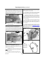
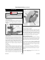
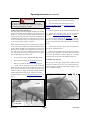
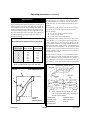
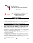
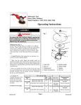
Milwaukee Tool
Item: 10” Magnum® Compound Miter Saw
Model Numbers: 6494
Operating Instructions
SPECIAL FEATURES
The MILWAUKEE Magnum® Compound Miter Saw is highlighted by the following unique product features:
Unique Flip Fence System
MILWAUKEE’s unique flip fence can be adjusted to two different positions: one position for miter cuts and one position
for bevel & compound cuts. Typically, the fence system on
compound miter saws provides excellent work support for
compound miter cuts, but lacks support for general miter cuts.
MILWAUKEE revolutionized a new fence system that provides
superior work support for both compound and regular miter
cuts. The flip fence features a quick-change slot, which makes
adjustments simple.
Bevel Mechanism with Overtravel
The MILWAUKEE Magnum® Compound Miter Saw has a
bevel mechanism that allows the bevel angle to be adjusted to
0° to 50° on the left and 0° to negative 3° on the right. The
overtravel is provided by spring-loaded stops at 0° arid 45°
with travels to a-3° right bevel and a 500 left bevel. This feature is useful for -making precise cuts.
Longer Base Extension
The longer base extension provides better support for the
workpiece, especially for bevel cuts. The longer table also provides additional area for the operator to hold the workpiece
during a cut, resulting in more accurate cuts.
Detent Override
The detent override, when engaged, allows the table to
smoothly rotate to any miter angle. The table can be easily
locked at any miter angle. It is especially useful when making
small adjustments near 0°, 15°, 22.5° 30°, and 45°.
CAPACITY CHART
Compound
450 Miter & 450 Bevel
Cuts
900 Miter & 450 Bevel
Max. Height Max. Height Max. Width Max. Width
2-34/” W at
2-1/4” H
4” W at
1-13/16” H
4” W at
2-1/4” H
5-9/16” W at
1-13/16” H
ASSEMBLY
WARNING!
To reduce the risk of injury, always unplug tool
before attaching or removing accessories. Use
only specifically recommended accessories.
Others may be hazardous.
Mounting the Miter Saw (Fig. 3)
To prevent the tool from sliding, falling or tipping during operation, the saw can be mounted to a supporting surface such as
a level, sturdy worktable or bench. Position the saw and workbench to allow adequate room for cross-cutting long stock. To
mount the saw, insert fasteners through the four holes in the
base of the saw.
Fig. 3
CAPACITY CHART
Miter Cuts
Max. Height Max. Height Max. Width Max. Width
at 90o
at 45o
3-12” H at
3-7/8” W
3-12” H at
2-3/4” W
RenTrain INC
at 90o
at 45o
5-9/16” H at 3-7/8” H at
2-1/2” W
2-1/2” W
Page 1
1. Holes for mounting
1.
RenTrain INC
Operating Instructions (continued)
Installing the Clamp Handle (Fig. 4)
The Clamp Handle locks the selected miter angle. The tool is
shipped with the handle unassembled. To install the handle,
thread it clockwise into the tool as shown. To tighten the handle and lock the angle, turn the handle clockwise. To loosen
and unlock, turn it counterclockwise.
Fig. 4
gages. Use the supplied -wrench to loosen and remove the
left-hand thread blade screw clockwise (wrench is stored behind the right fence in wrench holder).
3.
Lift and hold the lower guard up. Remove the outer
blade flange, blade (if present), and the inner blade flange.
Wipe the flanges and spindle to remove dust and debris. .
4.
Install the inner blade flange as shown: Match the
arrow on the blade with the arrow on the tool casting. Then,
install the selected blade by sliding the blade between the gap
in the fence and then lifting the blade up to the spindle. Install
the outer blade flange.
5.
Press the spindle lock and rotate the blade until lock
engages while replacing and securely tightening the blade
screw counterclockwise with supplied wrench. Rotate the
blade screw guard into position and securely tighten the two
screws clockwise.
1. Holes for mounting
Raising and Lowering the Saw Head (Fig. 5)
The saw head locks down for transporting and storing the tool.
The tool is shipped with the saw head locked down. To unlock
it, gently press and hold the head down and simultaneously
pull the lock pin out. To lock the head, gently press and hold
the saw head down and then push the locking pin in.
Fig. 5
6.
Lower the saw head and check the clearance between
the blade and the turntable. The blade should rotate freely. If
the blade contacts the turntable, see “Adjustments” on page 9.
Return the wrench to the wrench holder. To change blades, follow the procedure above.
Fig. 6
1.
3.
2.
1. Blade
screw
guard
1.
2. Spindle
lock
2.
Fig. 7
1. Locking pin slides
2. Lock
1.
2.
1. Blade
2. Inner Flange
Installing and Changing Blades (Fig. 6 & 7)
Always use clean, sharp blades because dull blades tend to
overload the tool, bind and cause pinching. Use only 10”
blades rated at least 5500 RPM.
4.
3. Outer Flange
4. Blade Screw
1.
To install a blade, unplug the tool. Raise the saw head.
Loosen (do not remove) the two screws on the blade screw
guard counterclockwise.
2.
Rotate blade screw guard to expose blade screw.
Press the spindle lock and rotate the blade until the lock enRenTrain INC
Page 2
3.
RenTrain INC
Operating Instructions (continued)
OPERATION
Fig. 9
WARNING!
1.
To reduce the risk of injury, always wear eye protection..
Always wait for the blade to stop completely before making adjustments or servicing the tool. Do not defeat the
guards.
Collecting Dust (Fig. 8)
For dust collection, MILWAUKEE recommends using either
Dust Bag or a MILWAUKEE Vacuum Cleaner. The dust tube is
designed to accept a standard vacuum hose and swivels for
convenience.
Fig. 8
1. Upper Guard
2. Lower Guard
1. Dust Tube
2.
guard is opened with the saw head in the up position, the saw
head will not be able to be lowered.
1.
Select the Workpiece Carefully
Be cautious of pitchy, knottY, wet or warped stock. These
materials are likely to create pinching conditions. Workpieces
that bow and pinch may result in kick back. Inspect for and
remove nails before cutting. Always keep blades clean and
sharp; otherwise the blade produces a narrow kerf and is likely to be pinched by the workpiece. This tool is not recommended for cutting ferrous metals such as iron and steel.
Using Face Boards
There are holes in the fences for attaching face boards. Face
boards place distance between the fence and the workpiece,
providing improved support for some workpieces. For example, as the width of the face board increases, the height of the
workpiece which can be cut increases slightly (but the width
capacity decreases slightly). Similarly, if you place a face
board on the saw table and place a workpiece on top of the face
board, you can cut a workpiece with greater width (but with
less height).
Guards (Fig. 9)
The tool is shipped with both the upper and lower guard
installed. The lower guard should cover the blade when the
saw head is up and it should open automatically as the saw
head is lowered into the workpiece. If the lower guard appears
loose or if it does not move to cover the blade when the saw
head is up, take the saw to an authorized service center for
repairs. Do not attempt to open the guard further than the automatic action permits. The tool is designed so that when the
RenTrain INC
Support the Workpiece Properly
Always support the workpiece during operation. Otherwise,
the workpiece may tend to pull-up and into the saw. While
there are many ways to support and secure workpieces, MILWAUKEE advises using one of the following three methods.
1.
Use the Fence: (Fig. 10) Align the workpiece flush
against the fence as shown to provide a straight path for the
saw blade. This will help eliminate the tendency for the blade
teeth to bind. The fence can be used as a support for miter,
bevel and compound cuts.
2.
Use Vise No. 49-97-0110: (Fig. 11) Clamp the workpiece to the table using the MILWAUKEE vise as shown. The
vise fits into the slot on the back of the left fence. Vise sold
separately.
3.
Use a C-clamp: (Fig. 12) Clamp the workpiece to the
fence with a C-clamp as shown.
Page 3
RenTrain INC
Operating Instructions (continued)
Adjusting the Miter Angle (Fig. 13)
The saw cuts miter angles from 51° on the left to 59° on the
right. Angle markings appear on the scale that runs along the
perimeter of the base as shown. Nine angles are pre-set with
positive angle stops: 0° 15°, 22.5°, 30°, and 45° on both the left
and right side of the table.
Fig. 10
1.
To select a positive angle stop, be sure the clamp
handle is loosened.
Press the angle stop lever and rotate the turntable to the desired
angle. Tighten the clamp handle.
Supporting the workpiece against a fence during a
compound cut.
2.
To select other angles, the saw features an override
mechanism, which allows quick and accurate adjustments at
any angle.
To use the override, press the angle stop lever down and in
with your thumb until the lever engages with the lever lock.
Then rotate the turntable to desired angle. Tighten the clamp
handle securely clockwise. This feature is particularly useful
when making small adjustments near positive angle stops.
Fig. 11
Fig. 13
1. Miter angle scale
Supporting the workpiece with a vice.
1.
2.
3.
2. Positive angle stop
3. Lever lock
Fig. 12
4. Angle stop lever
4.
Supporting the workpiece with a C-clamp..
Adjusting the Bevel Angle (Fig. 14 & 15)
The bevel mechanism has twit positive spring-loaded stops:
one at 0° and one at 45°. The mechanism can be adjusted to
any angle in between by using the bevel angle scale, shown at
the rights The bevel mechanism has several degrees of overtravel on both the left and right; the saw can be adjusted to 50°
RenTrain INC
Page 4
RenTrain INC
Operating Instructions (continued)
on the left and to negative 3° on the right. To obtain the. overtravel, apply several pounds of force on the saw handle to
override the spring-loaded stops. Do not attempt to exceed the
stated overtravel.
1.
To adjust the bevel angle, place one hand on the front
handle for better control. Using the other hand, loosen the
bevel adjustment lever ,(clockwise if standing behind the tool;
counterclockwise if standing in front of tool).
2.
Pull or push the saw handle to desired position, using
the bevel angle scale as a guide.
3.
Tighten the bevel adjustment lever securely (clockwise if standing behind tool; counterclockwise if standing in
front of tool).
The tool is shipped so that the blade is square to the turntable.
If the blade becomes misaligned, it can be realigned using two
socket head cap screws.
1.
With the bevel angle adjusted to 0°, place one edge of a
90° square against the turntable and the other edge of the
square against the saw blade. If the blade is not square, use a
hex wrench to loosen or tighten the socket head cap screw A
(Fig. 16) until the blade is square.
2.
Once the blade is square, check to see if the bevel scale
pointer is=at 0°. If it is not, use a wrench to loosen the pointer
screw and move the pointer to 0°. 3.
Tilt the saw to a 45° bevel. Verify that the pointer reads
45°. If it does not, loosen or tighten the socket head cap screw
B (Fig. 17) until the pointer reads 45°.
Fig. 14
1. Bevel angle scale
Fig. 15
Fig. 16
1. Socket Head
Cap Screw A
2. Pointer Screw
3. Pointer
1.
1.
1.
2.
3.
Fig. 17
1. Bevel adjustment lever
1.
RenTrain INC
Page 5
1. Socket Head Cap Screw B
RenTrain INC
Operating Instructions (continued)
Using the Flip Fence (Fig. 16-18)
The saw features a flip fence which can be positioned for regular miter cuts and for compound cuts as shown. This feature
helps to provide superior support for both types of cuts.
Fig. 20
1.
Fence is in the miter position.
3.
With the fence lock lever parallel with the fence, insert
the fence lock lever through the fence slot. Then, turn the fence
lock lever securely clockwise to secure the fence to the tool.
Fig. 18
1. Fence lock lever
NOTE: Verify that the clamp on the mechanism has rotated to
a vertical position 90° to the slot. This position is required for
proper clamping.
1.
To adjust the fence, turn the fence lock lever counterclockwise to loosen it. When the fence lock lever is parallel
with the fence slot, pull the fence away from the saw. A firm
detent must be overridden to accomplish this.
2.
Position the fence for the desired cut. The photos shown
illustrate the proper fence position for miter cuts (Fig. 20) and
for compound cuts (Fig. 19). Always be sure to position the
fence properly for maximum work support.
Fig. 19
Starting and Stopping the Tool
Always hold the handle firmly because the starting and stopping action of the motor may cause the handle to move up or
down slightly. Always secure the turntable by tightening the
clamp handle when setting miter angles (see “Adjusting the
Miter Angle” and “Adjusting the Bevel Angle” on page 4).
Always make sure the spindle lock is released so the blade is
free to rotate. To start the motor, pull the trigger. To stop the
motor, release the trigger.
Electric Brake
The Miter Saw features an electric brake. The brake engages
when the trigger is released, causing the blade to stop and
allowing you to proceed with your work. Generally the saw
blade stops in four to five seconds. However, there may be a
delay between the time the trigger is released and the time the
brake engages. Occasionally the brake may miss completely. If
the brake misses frequently, the saw needs servicing by an
authorized MILWAUKEE service station. The brake is not a
substitute for the guards, so it is essential to always wait for the
blade to stop completely before removing the blade from the
kerf. The correct brush grade must be used for proper operation of the brake. Use only identical MILWAUKEE replacement brushes when servicing the tool.
Fence is in the compound cut position.
RenTrain INC
Page 6
RenTrain INC
Operating Instructions (continued)
Making a Cut
1.
Plug in the tool. Raise the saw head completely.
WARNING!
To reduce the risk of injury, do not rely on the brake as a
safety feature. Always wait until the blade stops completely
before allowing anything near the blade.
2.
Select the desired angle following the steps in
“Adjusting the Miter Angle” and “Adjusting the Bevel
Angle” on page 4.
Cutting the Kerf Plate Slot (Fig. 21)
The tool is shipped with the kerf plate installed; never attempt
to make a cut without the plate installed. The kerf plate is NOT
factory cut, so the first cut you make with the tool will be to
create a kerf slot. The angle of the kerf slot for compound cuts
is different than that for miter cuts. Therefore, it is necessary
to cut new kerf slots for each type of angle. Generally, it is best
to cut a kerf slot before cutting a workpiece.
3.
When cutting a kerf slot, be sure to use the blade you intend to
use for your work since blades have different widths that affect
the kerf. When changing from a thick blade to a thinner one,
you may want to purchase a new kerf plate and cut a new kerf
slot. Also, bevel cuts require a different kerf slot than miter
cuts, so always be sure to cut a new slot for bevel cuts. Cut the
kerf slot following the procedure below.
1.
To cut a kerf slot, plug in tool and hold handle firmly.
2.
Start the motor following the instructions on page 6.
3.
Wait a few seconds for the blade to reach full speed.
Place the workpiece on the turntable and line up the cut.
4.
Support the workpiece using any of the methods
described in “Support the Workpiece Properly” on page 3..
5.
Start the motor following the instructions on page 6.
Wait a few seconds for the blade to reach full speed. Then gently lower the saw head into the workpiece all the way through
the cut.
6.
Always allow the saw to do the work. Forcing the tool
may stall or overheat the motor.
7.
After the cut is complete, release the trigger and wait for
the blade to stop completely. Then gently raise the saw head
and remove the workpiece. Always unplug the tool before
retrieving loose cut-off pieces from inside the guard area.
Lock-Off Feature (Fig. 22)
4.
To help prevent damaging the kerf plate, gently and
slowly lower the saw head to the full depth of cut (the point
where the head will not lower any further). When the cut is
complete, release the trigger. WAIT FOR THE BLADE TO
STOP COMPLETELY before gently raising the saw head.
To alter the depth of cut; read “Adjusting the Depth of Cut” on
page 9.
There is a hole in the trigger through which a padlock will fit
to lock the tool when it is not in use. Use a padlock with a 1/4”
shackle and always unplug the tool before installing it (padlock not supplied with tool).
1. Trigger with hole for padlock
1.
Fig. 22
Fig. 21
1. Kerf slot
2. Kerf plate
RenTrain INC
1.
2.
Page 7
RenTrain INC
Operating Instructions (continued)
Applications
Cutting Compound Miters (Fig. 23 & 24)
Fig. 23 identifies miter and bevel settings for various types of
crown molding for 90° corners. Note that these are-ideal settings and may vary because many moldings have slightly different spring angles and some walls are not perfectly square.
If the wall or ceiling is bumpy, the miter angle will not hold
true, so the bumps may need to be sanded. Fig. 24 illustrates
the relationship between the spring angle, the ceiling, the
wall and the molding.
Fig 23.
Angle Settings for Compound Saw (for 900 corner)
Type of Crown
(spring angle)
Miter
Miter
(angle of table) (angle of blade)
300
350
380
400
450
520
26.60
29.80
31.60
32.70
35.30
38.20
37.80
35.40
33.90
32.80
30.00
25.80
Positioning Crown Molding on The Saw (Fig. 25 & 26)
Determining how to lay a workpiece on the miter saw table
for cutting molding can be tricky for even the experienced
woodworker. Figs. 25 & 26 and these instructions serve as a
guideline.
The wood labeled A, B, C & D in Fig. 25 are the four pieces
of wood that form an inside and an outside corner. Each
piece of wood has:
a “top” edge, which is against the ceiling
a “left” or “right” name
a “face,” which is the visible surface
z
z
z
Fig. 26 illustrates three different views of wood pieces A, B,
C & D. Wood A1, 131, C1 & D1 shows the wood lying flat on
a table. Dashed lines on the wood pieces indicate that the
bevel is “hidden”, meaning it is on the underside of the wood.
When the inside corner woods Al and 131 are lying flat on a
table, the bevel faces are exposed (i.e. on top). However, when
the outside corner woods C1 and D1 are lying flat on a table,
they have “hidden” bevel faces, meaning the bevel angle is on
the underside of the. wood.
Wood pieces A2, A3, B2, B3, C2, C3, D2 and D3 illustrate A,
B, C, & D lying on the miter saw table both face up and face
down as indicated. Using these illustrations as a guide, it is
easy to determine how to lay the wood against the miter saw
fence and how to set the miter and bevel angle for a compound
cut.
Wood is positioned flat on the miter saw table.
Inside Corner
Outside Corner
Fig. 25
Fig. 24
e
Crown Molding Profile
1.
Top
Left Face
Top
Right Face
p c
Tot Fa
gh
Ri
p e
To Fac
ft
Le
Blade Kerf
Here
Blade Kerf
Here
A1
Top
Left Face
3
Top B1
Right Face
C1
A3
poT
ecaF tfeL
C2Left Face
Top
Miter Saw Fence
Miter Saw Fence
A2
Top
Left Face
* *
Miter Saw Fence
Top
Right Face
B2
D1
Top
Right Face
Top
Left Face
Right Face B3
Top
*
Top
Left Face
2.
Miter Saw Fence
D2 poT
ecaF thgiR
*
Top
D3
Right Face
Face Up
Face Up
z
1. Ceiling
2. Wall
3. Spring Angle
C3
These workpieces are Face Down. Face down
cuts can be used in special cases, depending on
the type of crown molding.
Inside Corner
Blade kerf here
Outside Corner
Miter saw fence
Top left face
Face up
Top right face
RenTrain INC
Page 8
RenTrain INC
Operating Instructions (continued)
Adjustments
Fig. 25
1.
Adjusting the Fences
The left fence is fastened to the Miter Saw with three screws
and the right fence is attached with two screws. The tool is
shipped with the fences aligned and square. If the screws
loosen, the fences may lose its alignment, possibly resulting
in inaccurate cuts.
1.
To realign the fences, unplug the tool. Adjust the miter
and bevel angles to 0°.
2.
Place a square flat on the saw table as shown with one
edge along the left fence and the other edge along the blade.
The left fence should be perfectly perpendicular to the
blade. If it is not, loosen the three screws fastening the
fence to the tool. Then slide the left fence until it is
square to the blade. Securely tighten the three screws.
1. Depth adjustment screw with lock nut
3.
After the left fence is aligned, use a straight edge to
align the right fence to the left fence.
Then make a sample cut and adjust as necessary.
Verify that the pointer is at 0°.
To adjust the depth of the depth adjustment set screw, slightly
raise the saw head to reduce the depth of cut or slightly lower
the saw head to increase the depth of cut. Make only a
SLIGHT adjustment.
Adjusting the Depth of Cut (Fig. 25)
1.
To adjust the depth of cut, unplug the tool. Loosen
(counterclockwise) the lock nut located on the back of the
tool as shown.
2. To adjust the depth of the depth adjustment set screw,
slightly raise the saw head to reduce the depth of cut or lightly lower the saw head to increase the depth of cut. Make only
a slight adjustment.
3.
Securely tighten the lock nut.
4.
Make a sample cut and adjust as necessary.
RenTrain INC
Page 9
RenTrain INC