1
2003
AIR-COOLED SPLIT-TYPE
PACKAGED AIR CONDITIONERS
TECHNICAL & SERVICE MANUAL
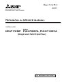
<Outdoor unit>
Models
HEAT PUMP PUH-P8MYA, PUH-P10MYA
(Single and Twin/Triple/Four)
For use with the R407C
Contents
Page
1
PRECAUTIONS FOR DEVICES THAT USE R407C REFRIGERANT ...................................... 1
[1] Storage of Piping Material ................................................................................................... 2
[2] Piping Machining ................................................................................................................. 3
[3] Necessary Apparatus and Materials and Notes on Their Handling ..................................... 4
[4] Brazing ................................................................................................................................. 5
[5] Airtightness Test .................................................................................................................. 6
[6] Vacuuming ........................................................................................................................... 6
[7] Charging of Refrigerant ....................................................................................................... 7
2
SPECIFICATIONS ...................................................................................................................... 8
3
EXTERNAL DIMENSIONS ....................................................................................................... 10
4
ELECTRICAL WIRING DIAGRAM ............................................................................................ 11
[1] Outdoor Unit ....................................................................................................................... 11
[2] Skelton of Indoor/Outdoor Connection .............................................................................. 12
5
Technical Data of PUH-8/10YD to Meet LVD ......................................................................... 13
[1] Standard Operation Data ................................................................................................... 13
[2] Cooling Capacity Curves ................................................................................................... 15
[3] Heating Capacity Curves ................................................................................................... 15
[4] Capacity Reduction Ratio due to Changes in Piping Length ............................................. 16
[5] Center of Gravity (Outdoor unit) ........................................................................................ 17
[6] NC Curve (Outdoor unit) ................................................................................................... 18
6
SERVICE DATA ........................................................................................................................ 19
[1] Appearance of Equipment ................................................................................................. 19
[2] Refrigerant Circuit .............................................................................................................. 21
[3] Limitation of Refrigerant Piping Length .............................................................................. 21
[4] Refrigerant Piping .............................................................................................................. 22
[5] Refrigerant Charge ............................................................................................................ 22
[6] Operation Rage ................................................................................................................. 22
7
CONTROL ................................................................................................................................ 23
[1] Composition of Control ...................................................................................................... 23
[2] Control specifications ......................................................................................................... 24
[3] Function of switches and connectors (outdoor unit) .......................................................... 28
[4] Simple parts check method ............................................................................................... 36
[5] Reference Data .................................................................................................................. 37
[6] Troubleshooting of each part ............................................................................................. 38
[7] Emergency operation ......................................................................................................... 41
[8] Self-diagnosis and troubleshooting .................................................................................... 43
8
Test run .................................................................................................................................... 53
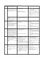
¡ PRECAUTIONS FOR DEVICES THAT USE R407C REFRIGERANT
Caution
Do not use the existing refrigerant piping.
Use a vacuum pump with a reverse flow check valve.
•
•
The old refrigerant and refrigerator oil in the existing
piping contains a large amount of chlorine which may
cause the refrigerator oil of the new unit to deteriorate.
Do not use the following tools that have been used
with conventional refrigerants.
(Gauge manifold, charge hose, gas leak detector, reverse flow check valve, refrigerant charge base,
vacuum gauge, refrigerant recovery equipment)
Use refrigerant piping made of phosphorus deoxidized copper and copper alloy seamless pipes and
tubes”. In addition, be sure that the inner and outer
surfaces of the pipes are clean and free of hazardous
sulphur, oxides, dust/dirt, shaving particles, oils,
moisture, or any other contaminant.
•
•
If the conventional refrigerant and refrigerator oil are
mixed in the R407C, the refrigerant may deteriorated.
• If water is mixed in the R407C, the refrigerator oil
may deteriorate.
• Since R407C does not contain any chlorine, gas
leak detectors for conventional refrigerants will not
react to it.
Contaminants on the inside of the refrigerant piping
may cause the refrigerant residual oil to deteriorate.
Store the piping to be used during installation indoors
and keep both ends of the piping sealed until just
before brazing. (Store elbows and other joints in a
plastic bag.)
•
The vacuum pump oil may flow back into the refrigerant cycle and cause the refrigerator oil to deteriorate.
Do not use a charging cylinder.
•
If dust, dirt, or water enters the refrigerant cycle,
deterioration of the oil and compressor trouble may
result.
Using a charging cylinder may cause the refrigerant
to deteriorate.
Be especially careful when managing the tools.
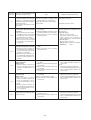
Use ester oil, ether oil or alkylbenzene (small
amount) as the refrigerator oil to coat flares and
flange connections.
•
•
If the refrigerant leaks, recover the refrigerant in the
refrigerant cycle, then recharge the cycle with the
specified amount of the liquid refrigerant indicated
on the air conditioner.
The refrigerator oil will degrade if it is mixed with a
large amount of mineral oil.
If dust, dirt, or water gets in the refrigerant cycle, the
refrigerant may deteriorate.
Use liquid refrigerant to seal the system.
•
•
If gas refrigerant is used to seal the system, the composition of the refrigerant in the cylinder will change
and performance may drop.
Do not use a refrigerant other than R407C.
•
If another refrigerant (R22, etc.) is used, the chlorine
in the refrigerant may cause the refrigerator oil to deteriorate.
–1–
Since R407C is a nonazeotropic refrigerant, if additionally charged when the refrigerant leaked, the composition of the refrigerant in the refrigerant cycle will
change and result in a drop in performance or abnormal stopping.
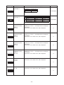
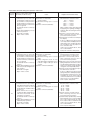
[1] Storage of Piping Material
(1) Storage location
NG
OK
Store the pipes to be used indoors. (Warehouse at site or owner’s warehouse)
Storing them outdoors may cause dirt, waste, or water to infiltrate.
(2) Pipe sealing before storage
OK
NG
Both ends of the pipes should be sealed until immediately before brazing.
Wrap elbows and T’s in plastic bags for storage.
* The new refrigerator oil is 10 times more hygroscopic than the conventional refrigerator oil (such as Suniso). Water
infiltration in the refrigerant circuit may deteriorate the oil or cause a compressor failure. Piping materials must be stored
with more care than with the conventional refrigerant pipes.
–2–
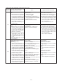
[2] Piping Machining
Use ester oil, ether oil or alkylbenzene (small amount) as the refrigerator oil to coat flares and flange connections.
Use only the necessary minimum quantity of oil.
Reason:
1. The refrigerator oil used for the equipment is highly hygroscopic and may introduce water inside.
Notes:
• Introducing a great quantity of mineral oil into the refrigerant circuit may also cause a compressor failure.
• Do not use oils other than ester oil, ether oil or alkylbenzene.
–3–
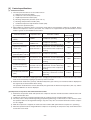
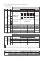
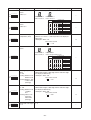
[3] Necessary Apparatus and Materials and Notes on Their Handling
The following tools should be marked as dedicated tools for R407C.
<<Comparison of apparatus and materials used for R407C and for R22>>
Apparatus Used
Use
R22
Gauge manifold
Charging hose
Charging cylinder
Gas leakage detector
Refrigerant collector
Refrigerant cylinder
Evacuating, refrigerant filling
Operation check
Refrigerant charging
Gas leakage check
Refrigerant collection
Refrigerant filling
Current product
Current product
Current product
Current product
R22
R22
Vacuum pump
Vacuum drying
Current product
Vacuum pump with a check valve
Flare tool
Bender
Application oil
Flaring of pipes
Bending of pipes
Applied to flared parts
Current product
Current product
Current product
Current product
Torque wrench
Pipe cutter
Welder and nitrogen cylinder
Refrigerant charging meter
Vacuum gauge
Tightening of flare nuts
Cutting of pipes
Welding of pipes
Refrigerant charging
Checking the vacuum degree
Current product
Current product
Current product
Current product
Current product
Symbols:
To be used for R407C only.
R407C
Do not use
Shared with R134a
For R407C use only
Identification of dedicated use for R407C:
Record refrigerant name
and put brown belt on
upper part of cylinder.
Can be used by attaching an adapter with a
check valve.
Ester oil or Ether oil or
Alkybenzene (Small
amount)
Can also be used for conventional refrigerants.
Tools for R407C must be handled with more care than those for conventional refrigerants. They must not come into contact
with any water or dirt.
–4–
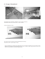
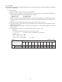
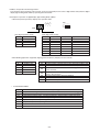
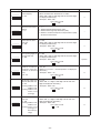
[4] Brazing
No changes from the conventional method, but special care is required so that foreign matter (ie. oxide scale, water, dirt,
etc.) does not enter the refrigerant circuit.
Example: Inner state of brazed section
When non-oxide brazing was not used
When non-oxide brazing was used
Items to be strictly observed:
1. Do not conduct refrigerant piping work outdoors on a rainy day.
2. Apply non-oxide brazing.
3. Use a brazing material (BCuP-3) which requires no flux when brazing between copper pipes or between a copper
pipe and copper coupling.
4. If installed refrigerant pipes are not immediately connected to the equipment, then braze and seal both ends of them.
Reasons:
1. The new refrigerant oil is 10 times more hygroscopic than the conventional oil. The probability of a machine failure if
water infiltrates is higher than with conventional refrigerant oil.
2. A flux generally contains chlorine. A residual flux in the refrigerant circuit may generate sludge.
Note:
• Commercially available antioxidants may have adverse effects on the equipment due to its residue, etc. When
applying non-oxide brazing, use nitrogen.
–5–
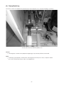
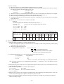
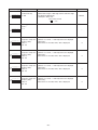
[5] Airtightness Test
No changes from the conventional method. Note that a refrigerant leakage detector for R22 cannot detect R407C leakage.
NG
NG
Halide torch
R22 leakage detector
Items to be strictly observed:
1. Pressurize the equipment with nitrogen up to the design pressure and then judge the equipment’s airtightness, taking
temperature variations into account.
2. When investigating leakage locations using a refrigerant, be sure to use R407C.
3. Ensure that R407C is in a liquid state when charging.
Reasons:
1. Use of oxygen as the pressurized gas may cause an explosion.
2. Charging with R407C gas will lead the composition of the remaining refrigerant in the cylinder to change and this
refrigerant can then not be used.
Note:
• A leakage detector for R407C is sold commercially and it should be purchased.
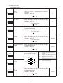
[6] Vacuuming
1. Vacuum pump with check valve
A vacuum pump with a check valve is required to prevent the vacuum pump oil from flowing back into the refrigerant
circuit when the vacuum pump power is turned off (power failure).
It is also possible to attach a check valve to the actual vacuum pump afterwards.
2. Standard degree of vacuum for the vacuum pump
Use a pump which reaches 0.5 Torr (500 MICRON) or below after 5 minutes of operation.
In addition, be sure to use a vacuum pump that has been properly maintained and oiled using the specified oil. If the
vacuum pump is not properly maintained, the degree of vacuum may be too low.
3. Required accuracy of the vacuum gauge
Use a vacuum gauge that can measure up to 5 Torr. Do not use a general gauge manifold since it cannot measure a
vacuum of 5 Torr.
4. Evacuating time
•
Evacuate the equipment for 1 hour after –755 mmHg (5 Torr) has been reached.
•
After envacuating, leave the equipment for 1 hour and make sure the that vacuum is not lost.
5. Operating procedure when the vacuum pump is stopped
In order to prevent a backflow of the vacuum pump oil, open the relief valve on the vacuum pump side or loosen the
charge hose to drawn in air before stopping operation.
The same operating procedure should be used when using a vacuum pump with a check valve.
–6–
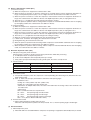
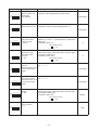
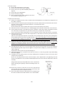
[7] Charging of Refrigerant
R407C must be in a liquid state when charging, because it is a non-azeotropic refrigerant.
For a cylinder with a syphon attached
For a cylinder without a syphon attached
Cylinder
Cylinder
Cylinder color identification
Valve
R407C-Gray
R410A-Pink
Charged with liquid refrigerant
Valve
Liquid
Liquid
Reasons:
1. R407C is a mixture of 3 refrigerants, each with a different evaporation temperature. Therefore, if the equipment is
charged with R407C gas, then the refrigerant whose evaporation temperature is closest to the outside temperature is
charged first while the rest of refrigerants remain in the cylinder.
Note:
• In the case of a cylinder with a syphon, liquid R407C is charged without turning the cylinder up side down. Check the
type of cylinder before charging.
–7–
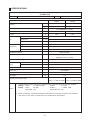
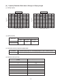
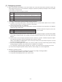
2 SPECIFICATIONS
Specifications of air-source heat pump type packaged air conditioner
(Outdoor unit)
PUH-P8MYA
Model name
Capacity
Quantity
Cooling
Heating
kcal/h
18,000
20,400
kW
20.9
23.7
Power source
3N~ 380/400/415 V 50 Hz
Power input
kW
7.27
7.17
A
13.0
12.8
Current
Propeller fan × 1
Type x Quantity
Fan
Airflow rate
Motor output
3
m /min
185
kW
0.38
Type
Compressor
Hermetic
Motor output
kW
5.5
Crankcase heater
kW
0.05 (240V)
Refrigerant/Lubricant
R407C/FVC68D
External finish
Steel plate painting with polyester powder
(MUNSELL 5Y8/1 or similar)
External dimension
Protection
High pressure protection
device
Compressor/Fan
Refrigerant piping diameter
mm
1,715(H) × 990(W) × 840(L)
MPa
3.3
Overcurrent protection/Thermal switch
Liquid/Gas
mm
Indoor unit
ø12.7 Flare / ø25.4 Flange
PEH-P8MYA
Noise level
dB (A)
56
Net weight
kg
215
Indoor: 15 °CWB~24 °CWB Indoor: 15°CDB~27 °CDB
Operating temperature range
Outdoor: –5 °CDB~46 °CDB Outdoor: –12 °CWB~18 °CWB
Notes:
1. Cooling/Heating capacity indicates the maximum value at operation under the following condition.
Cooling Indoor:
27 °CDB/19 °CWB
Outdoor:
35 °CDB
Heating
Indoor:
20 °CDB
Outdoor:
7 °CDB/6 °CWB
Pipe length: 7.5m
Height difference: 0m
2. Works not included: Installation/Foundation work, Electrical connection work, Duct work, Insulation
work, Power source switch, and other items not specified in this specifications.
–8–
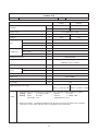
Specifications of air-source heat pump type packaged air conditioner
(Outdoor unit)
PUH-P10MYA
Model name
Capacity
Quantity
Cooling
Heating
kcal/h
22,400
26,200
kW
26.0
30.5
3N~ 380/400/415V 50Hz
Power source
Power input
kW
9.02
8.62
A
16.0
15.4
Current
Propeller fan × 1
Type x Quantity
Fan
Airflow rate
Motor output
3
m /min
185
kW
0.38
Hermetic
Type
Compressor
Motor output
kW
7.5
Crankcase heater
kW
0.05 (240V)
R407C/FVC68D
Refrigerant/Lubricant
Steel plate painting with polyester powder
External finish
(MUNSEL 5Y8/1 or similar)
External dimension
Protection
High pressure protection
device
Compressor/Fan
Refrigerant piping diameter
mm
1,715(H) × 990(W) × 840(L)
MPa
3.3
Overcurrent protection/Thermal switch
Liquid/Gas
mm
ø12.7 Flare / ø28.6 Flange
PEH-P10MYA
Indoor unit
Noise level
dB (A)
57
Net weight
kg
220
Indoor: 15 °CWB~24 °CWB Indoor: 15 °CDB~27 °CDB
Operating temperature range
Notes:
Outdoor: –5 °CDB~46 °CDB
Outdoor: –12 °CWB~18 °CWB
1. Cooling/Heating capacity indicates the maximum value at operation under the following condition.
Cooling Indoor:
27 °CDB/19 °CWB
Outdoor:
35 °CDB
Heating
Indoor:
20 °CDB
Outdoor:
7 °CDB/6 °CWB
Pipe length: 7.5 m
Height difference: 0 m
2. Works not included: Installation/Foundation work, Electrical connection work, Duct work, Insulation
work, Power source switch, and other items not specified in this specifications.
–9–
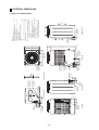
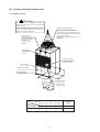
80
25
Rear view
Knockout hole
Rear piping hole
(It is necessary
for the option)
73
237
198
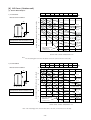
Connecting pipe
8 : φ25.4<brazed>
10 : φ28.6<brazed>
100
160
251
378
55
Y
Left side view
80
60
φ 25.4 Knockout hole
<Bottom side hole for
the control wiring>
φ25.4 Knockout hole
<Left side hole for
the control wiring>
Knockout hole
Left piping hole
Cross section X-X
234
Note 1
Knockout hole
Bottom piping hole
121
50
40
75
φ38.1 Knockout hole
<Left side hole for
the power supply>
Cross section Y-Y
Knockout hole
Front piping hole
Refrig. service
valve (liquid)
φ12.7<flare>
Knockout hole
Pressure gauge
(for option)
4-14X20 holes
<For mounting
anchor bolt M8>
(Field supply)
Refrig. service
valve(gas)
<flange>
80
165
79
31
X
215
413
55
Front view
190
215
Note 3
Knockout hole
<Front side hole for
the power supply and
control wiring>
Plane view
990
560
840
Service panel
X
15
880
15
225
Note 2
φ 38.1 Knockout hole
<Bottom side hole for
the power supply>
194
910
1715
Y
149
5
40
70
6
100
48
65
φ25.4 Knockout hole
<Right side hole for
the control wiring>
Air
inlet
Right side view
φ38.1 Knockout hole
<Right side hole for
the power supply>
Air outlet
Air
inlet
Note: 1. Please leave a space under the outdoor unit for
the piping when you connected the piping from
the bottom.
(Please be careful not to close the hole of the
bottom plate by the basement.)
2. It is possible to change to φ27 or φ 34 by selecting
the conduit mounting plate.
3. The hole size can be selected to φ 27 or φ 34 or
φ 40 by selecting the conduit mounting plate.
60
84
–10–
1490
<Accessory>
• Refrigerant connecting pipe ...................................... 1pc.
(The connecting pipe is fixed with the unit)
• Packing for connecting pipe ...................................... 1pc.
(It is attached control box cover)
• Conduit mounting plate
(Painted the same color as the unit body)
φ 27 ............................................................................ 1pc.
φ 34 ............................................................................ 1pc.
φ 40 ............................................................................ 1pc.
• Tapping screw 4 x 12 .............................................. 4pcs.
3 EXTERNAL DIMENSIONS
• Models PUH-P8MYA/P10MYA
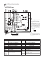
4 ELECTRICAL WIRING DIAGRAM
[1] Outdoor Unit
• Model PUH-P8MYA/P10MYA
63H1
CH
MC
SV1
(*1)
63L
21S4
RED
WHITE
BLACK
C11
(3P)
1
TH1
LEV
MF
3
1
3
C12
(3P)
51C
1
CNMNT
(5P)
CNVMNT
(3P)
CN23 (3P)
CN40
(6P)
TH2
TH3
2 1
2 1
2 1
CN2
(2P)
CN3
(2P)
CN4
(2P)
3
1
CN22 (3P)
1
CN21 (3P)
OFF
3
52C
1
3
51C
52C
5
52C
1
5
1
6
3
5
1
F10
OFF
SW3
LED1
12
OFF
1
63H2
6
CN24 3
(3P)
SW1
SW4
1
CN25 (3P)
O
OFF
CN53 (3P)
X01
CN52 (6P)
X02
1
SW2
CN27
(3P)
6
Note :
1. Be sure to apply earth work to the unit.
(Use the earth terminal of TB1.)
2. The dotted lines show field wiring.
3. Color of earth wire is yellow and green
twisting.
4. This motor (*1) includes auto reset type
internal thermostat.
5. Indoor and outdoor connecting wires
(*2) are made with polarities, make
sure matching wiring and terminal.
6. SW5 (*3) is shown PUH-P10MYA setting.
In case of PUH-P8MYA setting is
shown as below.
Transmission
Circuit
7 CN20 (7P)
F01
DC power
supply
F04
1
C14
(2P)
CN51
(5P)
CNFC1 (6P)
6
L1
N
L2
L3
1
CN81
(3P)
F30
N.F.BOARD
2
X05
5
6
1
CNIN
(7P)
RED
WHITE
BLACK
BLUE
X03
3
3
F20
7
1
CN3N
(3P)
O
3
CNOUT2
(3P)
1
SW5
3
1
CNOUT1 3
(5P) 1
CN3S 3 X1
(3P)
4
X04
CN26 (5P)
5
1
CNFAN
(5P)
CNFC2
F.C.
(6P)
BOARD
CNPO
(5P)
1
O
3
1
CN3D
(3P)
(*3)
O
3
F02
F03
GREEN/YELLOW
F1
PE
3
1
3
CN34
(3P)
CN28
(3P)
CNS3
(3P)
CNFG
(3P)
X1
F2
3
1
TB1
1
3
1
(*3)
TR
TB3
ON
TB8
OFF
1
L1 L2 L3 N PE
S1 S2 S3
PE
CIRCUIT BREAKER
(FIELD SUPPLY)
PUH-P8MYA-EU : 50A
PUH-P10MYA-EU: 60A
TO INDOOR UNIT
CONNECTING WIRES (*2)
(POLER)
INDOOR UNIT
POWER SUPPLY
3N~PE
380/400/415V
50HZ
Symbol
4
SW5
OUT OUT IN IN
S1
S2
S3
OUTDOOR UNIT CONTROL BOX
Caution :
1. To protect compressor from abnormal current, over current relays is installed. Therefore, do not change factory set value of over
current relays.
TB4
Name
Symbol
Name
F1, F2
FUSE (15A 250VAC CLASS T)
SW1~SW5
F01~F04
FUSE (6.3A 250VAC CLASS F)
21S4
4-WAY VALVE
F10~F30
FUSE (6.3A 250VAC CLASS F)
SV1
SOLENOID VALVE
51C
OVER CURRENT RELAY (COMPRESSOR)
CH
CRANK CASE HEATER (COMPRESSOR)
52C
MAGNETIC CONTACTOR (COMPRESSOR)
LEV
ELECTRINIC EXPANSION VALVE
63L
PRESSURE SWITCH (LOW PRESSURE)
TH1
63H1
PRESSURE SWITCH (HIGH PRESSURE)
TH2
63H2
PRESSURE SWITCH (FOR CONTROL)
TH3
COND./EVA. TEMP.
MC
COMPRESSOR MOTOR
TB1
POWER SOURCE TERMINAL BLOCK
MF
FAN MOTOR (OUTDOOR)
TB3, 4
OUTDOOR/INDOOR CONNECTION TERMINAL BLOCK
TR
TRANSFORMER
TB8
TERMINAL BLOCK (FOR 16, 20HP)
X1
AUXILIARY RELAY (FOR 16, 20HP)
C11, C12
CONNECTOR (FAN MOTOR)
LED 1
LED (FOR SERVICE)
C14
CONNECTOR (63H2)
XO1~X05
AUXILIARY RELAY (MAIN BOARD)
CAFAN, CNFC2
CN2,CN20~28
CNPO
CN3,34,30,3N,3S
CN4,40,51~53,81
SWITCH (MAIN BORD)
LIQUID TEMP.
THERMISTOR
DISCHARGE TEMP.
CONNECTOR (F. C. BOARD)
CNOUT1, 2
CONNECTOR MAIN BOARD
CNIN
CNFC1, FG, S3
CNMT,VMNT
–11–
CONNECTOR (N, F. BOARD)
[2] Skelton of Indoor/Outdoor Connection
(1) Applicable combinations of 8 & 10HP [PUH-P8MYA/P10MYA]
PUH-P8MYA
Indoor Units
PEH-P*MYA
PLH-P*KAH, PLH-P*AAH
PLA-P*KA, PLA-P*AA
PEHD-P*EAH, PEAD-P*EA
PCH-P*GAH, PCA-P*GA
PKH-P*GALH, PKH-P*FALH
PKA-P*GAL, PKA-P*FAL
PSH-P*GAH, PSA-P*GA
50 : 50
8HP
4HP+4HP
PEH-P*MYA
PLH-P*KAH, PLH-P*AAH
PLA-P*KA, PLA-P*AA
PEHD-P*EAH, PEAD-P*EA
PCH-P*GAH, PCA-P*GA
PKH-P*GALH, PKH-P*FALH
25 : 25 : 50
2HP+2HP
20 : 40 : 40
1.6HP+3HP
25 : 25 : 25 : 25
2HP+2HP
+2.5HP
–
+4HP
–
+3HP
–
+2HP+2HP
–
–
–
–
–
–
–
5HP+5HP
–
3HP+3HP
–
2.5HP+2.5HP
–
2HP+4HP
–
2.5HP+2.5HP+
+3HP
–
+5HP
–
+4HP
–
2.5HP+2.5HP
–
–
–
–
–
–
–
–
–
–
–
–
–
–
–
–
PKA-P*GAL, PKA-P*FAL
PSH-P*GAH, PSA-P*GA
Indoor Units
16HP
PEH-P*MYA
Indoor Unit
20HP
PEH-P*MYA
Multi distributor pipes
(Option)
indicates
applicable HP
*
33 : 33 : 33
2.5HP+2.5HP
–
10HP
Indoor Units
PUH-P10MYA
Single
–
–
–
–
–
–
–
–
–
–
–
–
–
–
–
–
SDD-50WSA-E SDT-111SA-E SDT-112SA-E SDT-122SA-E SDT-1111SA-E
–
(2) System
Single
Triple
Indoor units
Indoor unit
3-core cable
3-core cable
3-core cable
Transmission line
Transmission
line
*
Outdoor unit
Pipe work
Pipe work
*4-core cable
Distributor
Remote
controller
Remote
controller
Outdoor unit
Outdoor unit
Pipe work
* Two outdoor units connected when using PEH-P16·20MYA,
therefore 4-core cable required in order to send and receive
alternate defrost signal.
Indoor units
Twin
3-core cable
3-core cable
Transmission
line
Transmission
line
Distributor
Remote
controller
Outdoor unit
Pipe work
Indoor units
Four
Remote
controller
Outdoor unit
–12–
Pipe work
Distributor
5 Technical Data of PUH-P8MYA/P10MYA to Meet LVD
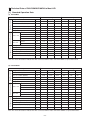
[1] Standard Operation Data
(1) PUH-P8MYA
Refrigerant circuit
Electrical characteristics
Operating condition
Operating condition
Cooling
Heating
Voltage
V
380
400
415
380
400
415
Power source frequency
Hz
50
50
50
50
50
50
Indoor air condition (DB/WB)
°C
27/19
27/19
27/19
20/–
20/–
20/–
Outdoor air condition (DB/WB)
°C
35/-
35/–
35/–
7/6
7/6
7/6
Piping length
m
7.5
7.5
7.5
7.5
7.5
7.5
Refrigerant charge
kg
7.9
7.9
7.9
7.9
7.9
7.9
A
13.0
13.0
13.0
12.8
12.8
12.8
kW
7.27
7.27
7.27
7.17
7.17
7.17
Compressor current
A
11.9
11.9
11.9
11.7
11.7
11.7
Fan current
A
1.1
1.1
1.1
1.1
1.1
1.1
Current
A
1.12
1.12
1.12
1.12
1.12
1.12
Input
kW
0.65
0.65
0.65
0.65
0.65
0.65
Discharge pressure
MPa
2.11
2.11
2.11
1.91
1.91
1.91
Suction pressure
MPa
0.48
0.48
0.48
0.40
0.40
0.40
Discharge refrigerant temperature
°C
75
75
75
70
70
70
Suction refrigerant temperature
°C
6
6
6
0
0
0
Liquid pipe temperature (at piping sensor)
°C
46
46
46
0
0
0
Compressor shell bottom temperature
°C
35
35
35
30
30
30
Current
Outdoor unit
Indoor unit
Input
Note: The values listed above indicate that when connected with the indoor unit PEH-P8MYA as representative data.
(2) PUH-P10MYA
Refrigerant circuit
Electrical characteristics
Operating condition
Operating condition
Cooling
Heating
Voltage
V
380
400
415
380
400
415
Power source frequency
Hz
50
50
50
50
50
50
Indoor air condition (DB/WB)
°C
27/19
27/19
27/19
20/–
20/–
20/–
Outdoor air condition (DB/WB)
°C
35/-
35/–
35/–
7/6
7/6
7/6
Piping length
m
7.5
7.5
7.5
7.5
7.5
7.5
Refrigerant charge
kg
8.4
8.4
8.4
8.4
8.4
8.4
A
16.0
16.0
16.0
15.4
15.4
15.4
Current
Outdoor unit
Indoor unit
Input
kW
9.02
9.02
9.02
8.62
8.62
8.62
Compressor current
A
14.9
14.9
14.9
14.3
14.3
14.3
Fan current
A
1.1
1.1
1.1
1.1
1.1
1.1
Current
A
1.64
1.64
1.64
1.64
1.64
1.64
Input
kW
0.94
0.94
0.94
0.94
0.94
0.94
Discharge pressure
MPa
2.22
2.22
2.22
1.75
1.75
1.75
Suction pressure
MPa
0.50
0.50
0.50
0.38
0.38
0.38
Discharge refrigerant temperature
°C
80
80
80
65
65
65
Suction refrigerant temperature
°C
8
8
8
–1
–1
–1
Liquid pipe temperature (at piping sensor)
°C
48
48
48
0
0
0
Compressor shell bottom temperature
°C
30
30
30
20
20
20
Note: The values listed above indicate that when connected with the indoor unit PEH-P10MYA as representative data.
–13–
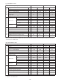
(3) PUH-P8MYA×2 units
Cooling
Operating condition
V
380
415
380
415
Power source frequency
Hz
50
50
50
50
Indoor air condition(DB/WB)
°C
27/19
27/19
20/-
20/-
Outdoor air condition(DB/WB)
°C
35/-
35/-
7/6
7/6
m
7.5
7.5
7.5
7.5
*1
kg
7.9
7.9
7.9
7.9
Current
A
13.0
13.0
12.8
12.8
kW
7.27
7.27
7.17
7.17
Compressor Current
A
11.9
11.9
11.7
11.7
Fan current
A
1.1
1.1
1.1
1.1
Current
A
4.5
4.1
4.5
4.1
kW
2.30
2.30
2.30
2.30
Discharge pressure
MPa
2.11
2.11
1.81
1.81
Suction pressure
MPa
0.52
0.52
0.40
0.40
Discharge refrigerant temperature
°C
75
75
70
70
Suction refrigerant temperature
°C
6
6
0
0
Liquid pipe temperature (at piping sensor)
°C
46
46
0
0
Compressor shell bottom temperature
°C
35
35
30
30
Operating condition
Voltage
Piping length
Electrial characterristics
Refrigerant charge
Refrigerant circuit
Heating
*1
Outdoor unit
Input
Indoor unit
Input
Note: The values listed above indicate that when connected with the indoor unit PEH-P16MYA as representative data.
*1: Value for one outdoor unit.
(4) PUH-P10MYA×2 units
Operating condition
Operating condition
Voltage
Electrial characterristics
Heating
V
380
415
380
415
Power source frequency
Hz
50
50
50
50
Indoor air condition(DB/WB)
°C
27/19
27/19
20/-
20/-
Outdoor air condition(DB/WB)
°C
35/-
35/-
7/6
7/6
Piping length
m
7.5
7.5
7.5
7.5
*1
kg
8.4
8.4
8.4
8.4
Current
A
16.0
16.0
15.4
15.4
kW
9.02
9.02
8.62
8.62
Compressor Current
A
14.9
14.9
14.3
14.3
Fan current
A
1.1
1.1
1.1
1.1
Current
A
5.1
4.7
5.1
4.7
kW
2.50
2.50
2.50
2.50
Discharge pressure
MPa
2.22
2.22
1.75
1.75
Suction pressure
MPa
0.50
0.50
0.38
0.38
Discharge refrigerant temperature
°C
80
80
65
65
Suction refrigerant temperature
°C
8
8
-1
-1
Liquid pipe temperature (at piping sensor)
°C
48
48
0
0
Compressor shell bottom temperature
°C
30
30
20
20
Refrigerant charge
Refrigerant circuit
Cooling
Outdoor unit
*1
Input
Indoor unit
Input
Note: The values listed above indicate that when connected with the indoor unit PEH-P20MYA as representative data.
*1: Value for one outdoor unit.
–14–
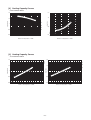
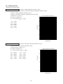
[2] Cooling Capacity Curves
• PUH-P8MYA/P10MYA
1.22
1.4
inlet air
wet b
u
lb te
1.2
Capacity ratio
20
18
16
mp.
1.1
<˚C
WB
>
Input ratio
Indoor
22
22
1
20
B>
W
m
0.6
Indoor
16
0.7
-5 -3 -1 1 3 5 7 9 11 13 15 17 19 21 23 25 27 29 31 33 35 37 39 41 43 45
lb
bu
et
w
ir
0.9
18
0.8
p.
C
<˚
te
ta
inle
-5 -3 -1 1 3 5 7 9 11 13 15 17 19 21 23 25 27 29 31 33 35 37 39 41 43 45
Outdoor air temperature <˚CDB>
Outdoor air temperature <˚CDB>
[3] Heating Capacity Curves
• PUH-P8MYA/P10MYA
1.4
1.4
15
20
25
25
B
CD
Input ratio
Capacity ratio
B>
>
˚
<
p.
em
bt
1
l
bu
ry
ir d
0.6
-12 -10 -8
le
r in
1
-6
ry
let
r in
oo
Ind
oo
Ind
15
˚CD
ta
0.8
20
1.2
1.2
d
air
b
bul
.<
mp
te
0.8
-4
-2
0
2
4
6
8
10 12
14 16 18
0.6
-12 -10 -8
-6
-4
-2
0
2
4
6
8
Outdoor air temperature <˚CWB>
Outdoor air temperature <˚CWB>
–15–
10 12
14 16 18
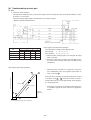
[4] Capacity Reduction Ratio due to Changes in Piping Length
(1) Cooling capacity
PUH-P8MYA
PUH-P10MYA
1
Capacity ratio
Capacity ratio
1
0.9
0.8
0
10
20
30
40
50
60
0.9
0.8
70
0
10
Equivalent piping length (m)
20
30
40
50
60
Equivalent piping length (m)
(2) Heating capacity
Equivalent piping length
Model name
- 30m
30 - 50m
50 - 70m
1.0
0.995
0.99
PUH-P8MYA
PUH-P10MYA
(3) Calculation formula of equivalent piping length
PUH-P8MYA
Equivalent piping length (m) = Actual piping length (m) + (0.47 × Number of bend)
PUH-P10MYA
Equivalent piping length (m) = Actual piping length (m) + (0.5 × Number of bend)
(4) Reduction ratio by frosting
Outdoor unit inlet wet bulb temperature
(°CWB)
Heating capacity reduction ratio
6
1.0
4
0.98
2
0.88
0
0.85
–2
0.86
–4
0.89
–6
0.92
–8
0.92
–10
0.92
–16–
70
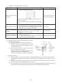
[5] Center of Gravity (Outdoor unit)
(1) Caution for Lifting
Warning
Lift unit slowly by suspending rope uniformly
so that the rope will not slip off or unit will not
incline seriously.
Be careful that unit may fall down if the rope is
not in a proper position as the center or
gravity of unit is being inclined.
Hanger rope (Over 7m × 2)
Protection pad
Use pads properly to
prevent the scratching of
external panel
caused by contact
with sling.
Below 40˚
Must be durable against unit weight.
For the lifting of unit for movement, please
be sure to suspend at four points, and not
to give any shock to unit.
Never apply two-point lifting as it is
dangerous.
Name plate
Indicates the unit
front side.
Center of gravity
Inclining to the right
front side of unit.
Service panel
G
Compressor position
Suspending spot
Z
2-point,front and rear
Y
X
Fasten here properly
to prevent unit from
slipping off from
the sling at lifting.
Center of gravity (mm)
Item
X
Y
Z
Net weight
(kg)
PUH-P8MYA
330
350
490
215
PUH-P10MYA
300
330
510
220
Model name
–17–
[6] NC Curve (Outdoor unit)
(1) Octave Band Analysis
63Hz
63
1) PUH-P8MYA
Measurement condition
250Hz
56
500Hz 1000Hz 2000Hz 4000Hz 8000Hz
55
50
45
42
39
(dB)
A
B
Sound pressure level in anechoic room
56 dB (A)
OCTAVE BAND PRESSURE LEVEL< dB> 0dB = 20µPa
70
1m
1m
125Hz
59
60
NC60
50
NC50
40
NC40
30
NC30
20
NC20
Approximate minimum
audible limit on
continuous noise
10
63
125
250
500
1000
2000
4000
8000
OCTAVE BAND CENTER FREQUENCIES <Hz>
Note: The measuring point is 1m from the bottom of the unit (1m from the front of the unit).
63Hz
63
2) PUH-P10MYA
Measurement condition
125Hz
60
250Hz
56
500Hz 1000Hz 2000Hz 4000Hz 8000Hz
56
51
47
44
40
(dB)
70
1m
A
B
Sound pressure level in anechoic room
57 dB (A)
OCTAVE BAND PRESSURE LEVEL< dB> 0dB = 20µPa
1m
60
NC60
50
NC50
40
NC40
30
NC30
20
NC20
Approximate minimum
audible limit on
continuous noise
10
63
125
250
500
1000
2000
OCTAVE BAND CENTER FREQUENCIES <Hz>
Note: The measuring point is 1m from the bottom of the unit (1m from the front of the unit).
–18–
4000
8000
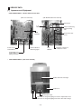
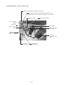
6 SERVICE DATA
[1] Appearance of Equipment
• PUH-P8MYA/P10MYA
Detail of Electrical Parts Box
(with cover removed)
(with Main Board Panel removed)
Transformer
F. C.
BOARD
Relay for defrosting
signal receiving
<X1>
MAIN
BOARD
Power source
terminal block
Terminal block for
defrosting signal
Overcurrent relay
<51C>
N. F.
BOARD
Magnetic contactor for
compressor <52C>
Terminal block for
outdoor/indoor control
wiring connection
• PUH-P8MYA/P10MYA (with cover removed)
Outdoor unit heat exchanger
Compressor
Electrical parts box
Ball valve for refrigerant piping connection <Liquid side> Flare
Ball valve for refrigerant piping connection <Gas side> Flange
–19–
• PUH-P8MYA/P10MYA
(Detail of machine room)
Thermistor <Condenser/evaporator temp.> TH3
(At the back of the heat exchanger panel (header cover).
When this screw is removed, the header cover is removed.)
Pressure switch
(63L)
Solenoid valve(SV1)
Pressure switch
(63H2)
4-way valve
Accumulator
Pressure switch
(63H1)
Electric expansion
valve (LEV)
Thermistor
<Liquid temp.>
TH1
Thermistor
<Discharge temp.>
TH2
Check joint
(low pressure)
Check joint
(high pressure)
–20–
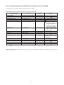
[2] Refrigerant Circuit
Outdoor unit
Service port
Strainer
Outdoor heat exchanger
Ball valve
High pressure switch
(Protection)
Service port
High pressure
switch (Control)
Strainer
Indoor heat exchanger
Low pressure
switch
(Protection)
Service port
Solenoid valve
Muffler
Indoor
units
Compressor
Accumulator
Electric expansion valve
Service port
Strainer
Capillary tube
Ball valve
Multiple-distributor
Flare connection
<
Cooling operation
Flange connection
<
Heating operation
Brazing connection
* Two outdoor units must be connected when using PEH-P16·20MYA.
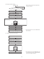
[3] Limitation of Refrigerant Piping Length
(1) Single
(2) Twin
a
b
h
PUH-P8,10
PUH-P8,10
H
H
L + a + b ≤ 70 m
L + a, L + b ≤ 50 m
a– b≤8m
H ≤ 40 m, h ≤ 1 m
L
L
L ≤ 50 m
H ≤ 40 m
(4) Four
(3) Triple
a
h
b
a
c
h
PUH-P8,10
H
b
c
d
H
L
L
PUH-P8,10
L + a + b + c ≤ 70 m
L + a, L + b, L + c ≤ 50 m
a – b, b – c , c – a ≤ 8 m
H ≤ 40 m, h ≤ 1 m
L + a + b + c + d ≤ 70 m
L + a, L + b, L + c, L + d ≤ 50 m
a – b , b – c , c – d, d –
H ≤ 40 m, h ≤ 1 m
a≤8m
* Total bends are 15 units, and max. bends are 8 units within L + a, L + b, L + c and L + d.
–21–
[4] Refrigerant Piping
Model
Gas pipe
Liquid pipe
PUH-P8MYA
ø25.4
ø 12.7
PUH-P10MYA
ø 28.58
ø 12.7
1.6, 2, 2.5, 3
ø 15.88
ø9.52
4, 5
ø19.05
ø 9.52
8
ø 25.4
ø 12.7
10
ø28.58
ø 12.7
16
ø25.4 × 2
ø12.7 × 2
20
ø28.58 × 2
ø12.7 × 2
Outdoor unit
Indoor unit
[5] Refrigerant Charge
Model
Amount of refrigerant
at ex-factory
PUH-P8MYA
R407C 6.0 kg
0.026× L + 0.014 × (
a
+
b
+
c
+
d)
+ 1.7(kg)
PUH-P10MYA
R407C 6.5 kg
0.026× L + 0.014 × (
a
+
b
+
c
+
d)
+ 1.7(kg)
Additional refrigerant charge
*1
*1
L: Main section actual length a + b + c + d: Join section actual length
The value of calculation result at the second decimal place must be rounded up to the first decimal place.
(e.g. 2.22 kg must be rounded up to 2.3 kg)
* 1 : For amount of total indoor units
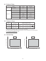
[6] Operation Rage
Heating
24
Indoor air temperature (°CDB)
Indoor air temperature (°CWB)
Cooling
15
-5
46
27
15
–12
Outdoor air temperature (°CDB)
18
Outdoor air temperature (°CWB)
–22–
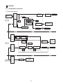
7 CONTROL
[1] Composition of Control
Indoor/outdoor
connection terminal
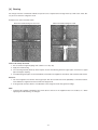
block
3N~
380/400/415 V
50 Hz
Electrical
terminal block
1. Function block diagram
outdoor
Magnetic
contractor
Fuse
Transformer
Fuse
DC5V for
microcomputer
Indoor/outdoor
connection terminal
block
Communication
circuit
Fuse
Fuse
Semiconductor
relay
4-way valve, LEV,
solenoid valve,
crankcase heater
Fan control
Outdoor fan
DC/DC
converter
Semiconductor
relay
LED1
indoor
Remote controller
terminal block
<Power>
Remote controller
terminal block
Remote
controller
Compressor
Over current
relay
Current
detection
LED2
<Supply power>
DC5V
12V
5V
Communication
circuit
Fan control
LED3
<Indoor/outdoor units communication>
Key input
LCD
Send/receive
–23–
Louver
Vane
Drain pump
Others
Indoor fan
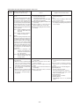
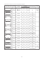
[2] Control specifications
(1) Protection functions
1) The main protection devices for the outdoor unit are:
a) High pressure protection (63H1)
b) Compressor overcurrent protection (51C)
c) Liquid temp thermistor trouble (TH1)
d) Discharge temperature protection (TH2 ≥118 °C)
e) Discharge temp thermistor trouble (TH2)
f) Condenser/evaporater temp thermistor trouble (TH3)
g) Low pressure protection (63L)
2) When tripping of a detection device is sensed, the check mode is entered and the compressor is stopped. (After 3
minutes, the compressor restarts.) Thereafter, the compressor is stopped when the specified number of check
modes or greater is sensed within the check time.
Protection functions
a) High pressure protection
(63H1)
b) Compressor overcurrent
protection (51C)
c) Liquid temp thermistor
trouble (TH1)
f) Condenser/evaporater
temp thermistor trouble
(TH3)
g) Low pressure protection
(63L)
Number of
Check time
check modes
3.3 MPa
Compressor operating
0
–
P8MYA: 22 A
P10MYA: 27 A
Compressor operating
1 time
30 minutes
1 time
30 minutes
2 times
30 minutes
1 time
30 minutes
1 time
30 minutes
2 times
30 minutes
Compressor operating except for
Less than –39 °C or 10 minutes at end of defrosting
and 7 minutes while compressor
greater than 88 °C
starting
d) Discharge temperature
Greater than 118 °C
protection (TH2 => 118 °C)
e) Discharge temp thermistor trouble (TH2)
Detection condition
Operation value
Compressor operating
Compressor operating except for
Less than 0 °C or 10 minutes at end of defrosting
greater than 216 °C and 5 minutes while compressor
starting
Compressor operating except for
Less than –39 °C or 10 minutes at end of defrosting
and 7 minutes while compressor
greater than 88 °C
starting
Compressor operating except for
defrosting, 10 minutes at end of
0 MPa
defrosting
3) Check mode is released by stopping operation, changing the operation mode, or check mode time up. A check
mode is also released by stopping of operation by remote controller.
4) Detected check mode history (newest) and abnormality history (last 2 times) are memorized and are displayed on
the segment by circuit board DIP switch setting.
The operation mode when the newest abnormality was generated, the thermistor temperature (TH1,2,3), and the
thermostat ON time can also be displayed.
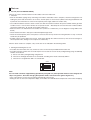
(2) Compressor, 4-way valve, and crankcase heater control
1) Determines the operation mode and operates the compressor based on the indoor/outdoor communication or MNET communication data.
2) Compressor control has a function which prevents the compressor from restarting within 3 minutes.
3) The 4-way valve is always ON during heating (except during defrosting). In other modes, it is OFF. However, when
the operation mode was changed from heating to stop, the 4-way valve is turned off 10 minutes after the compressor was stopped.
4) While the compressor is stopped, the crankcase heater remains ON. (OFF while the compressor is operating.)
5) When the operation mode is changed while the compressor is operating, the compressor stops and 3 minutes later
restarts in the new mode.
–24–
(3) Fan control
Controls the fan speed based on the piping temperature (TH1) to perform cooling at low outdoor temperatures and heating
at high outdoor temperatures.
1) Control at cooling
a) When the compressor stops, the fan stops (fan output=0%).
b) When the power is turned on, or when the compressor is restated after it has been stopped for 30 minutes or
longer, the piping temperature ( TH1) determines the fan output.
When TH ≤ 25˚C
Fan output = 100 %
When TH < 25˚C
Fan output = 60 %
c) When the compressor is restarted within 30 minutes after it has been stopped, the fan step before the compressor was stopped is selected. However, when the fan output was under 30% when the fan was stopped, 30% is
selected.
d) When the mode was changed from heating to cooling, the fan step conforms to item 2.
e) Two minutes after the fan is started, the fan step (number of units) is controlled every 30 seconds based on the
piping temperature (TH1).
f) When TH1 reaches 50˚C or higher, or when the control high pressure switch (63H2) tripped, the fan output
becomes 100%.
g) Fan output while the compressor is operating is within the 20% to 100% range.
• FAN step
The following expression determines the next fan step count nj+1:
nj + 1 = nj + ∆nj
nj: Current fan step, ∆nj: Displacement step amount
nj control
• If nj + 1 ≥ 100% nj + 1 = 100%
• If nj + 1 ≥ 20% nj + 1 = 20%
• If TH1 ≥ 50 °C or 63H2 is “OFF”
nj + 1=100%
FAN ∆nj
Outputs are all %.
20 ˚C Condensation temperature TH1
Current
output
20 ≤ nj < 50
50
≤ nj
100
t = 23
~
t = 26
~
t = 29
~
t = 33
~
t = 36
~
t = 40
~
t = 43
~
t = 46
~
~
Target condensation
t = 49
temperature 31 °C
t > 49 °C
t > 46
t > 43
t > 40
t > 36
t > 33
t > 29
t > 26
t > 23
t > 20
t≤
5
3
2
2
2
2
0
–2
–2
–3
–5
10
4
3
2
2
2
0
–2
–2
–4
–10
* In the night mode, the maximum value of nj is 80%. (When TH1 < 50˚C)
–25–
2) Control at heating
a) When the compressor is stopped and during defrosting, the fan is stopped.
b) When the power is turned on, or when the compressor is restarted after being stopped for 30 minutes or longer,
the piping temperature (TH1) determines the fan step.
TH1 > 8˚C
Fan output = 60%
TH1 ≤ 8˚C
Fan output = 100%
c) When the compressor is restarted within 30 minutes, the fan step is the step before the compressor was stopped.
d) When the mode is changed from cooling to heating, the fan step conforms to item b).
e) When returning from defrosting, the fan step is the step before defrosting.
f) Two minutes after the fan was restarted, the fan step is controlled every 30 seconds based on the piping
temperature (TH1).
g) When TH1 is –5˚C or lower, the fan output is made 100%.
• FAN step
The following expression determines the next fan step count nj + 1:
nj + 1 = nj + ∆nj
nj: Current fan step, ∆nj: Displacement step amount
nj control
• If nj + 1 ≤ 100% nj + 1 = 100%
• If nj + 1 ≤ 20% nj + 1 = 20%
• If TH1 < –5 °C nj + 1=100%
FAN ∆nj
Outputs are all %.
Evaporation temperature TH1
T=4
T=2
~
T=6
~
T=8
~
T = 11
~
T = 13
~
T = 15
~
T = 17
~
–10
T = 19
~
20 ≤ nj + 1 ≤ 100
T > 19 °C
~
Current
output
Target evaporation
temperature 10 °C
T > 17
T > 15
T > 13
T > 11
T>8
T>6
T>4
T>2
T>0
–4
–3
–2
–2
0
2
2
3
4
T≤ 0˚C
10
(4) Defrosting control
1) When the following conditions are satisfied, defrosting starts:
a) When the integrated compressor operation time has exceeded T1 (initial setting 50 minutes) and the piping
temperature (TH1) is below –10C
b) When the integrated compressor ˚C
Piping differential temperature
∆TH1 = TH10 – TH1
Current piping temperature
Piping temperature 10 minutes after starting or
10 minutes after returning from defrosting
2) The defrosting prohibit time T1 is set as following based on the defrosting time T2:
T2 ≤ 3 (minutes)
3 < T2 < 15
T2 = 15
T1 60 (minutes)
40
30
Note: T1 is reset at the end of defrosting, or by cooling ON command.
Note: When the compressor was stopped during defrosting, T1 = 20 minutes is set to recognize the stop as
defrosting end.
3) During defrosting, all the outdoor fans are stopped and the bypass solenoid valve (SV1) is turned ON and the 4-way
valve (21S4) is turned OFF.
4) When the following conditions are satisfied, defrosting ends:
a) T2 ≤ 2 mins
TH1 ≤ 30°C
b) 2 < T2 < 15 minutes
TH1 ≤ 8°C continuous 2 minutes
c) T2 =15 minutes
5) When the fan and 4-way valve (21S4) are turned ON at the end of defrosting, the heating mode is reset. Two
minutes after defrosting reset, the bypass solenoid valve (SV1) turns OFF.
6) When using PEH-P16·20MYA, alternate defrosting is possible after sending and receiving each respective
outdoor unit defrost signal.
–26–
(5) Bypass solenoid valve control (SV1)
1) Control at cooling
a) While the compressor is stopped, the solenoid valve is OFF.
b) When the power is turned on, or when the compressor is restarted after it has been stopped for 30 minutes or
longer, if the liquid temperature (TH1) is 25˚C or higher then the solenoid valve turns ON for 2 minutes.
c) When the power is turned on, or when the compressor restarted after it has been stopped for 30 minutes or
longer, the solenoid valve turns ON for 5 minutes if the liquid temperature (TH1) is staying below 25˚C.
d) The item b) or c) is applied to the mode change from heating to cooling.
e) When the previous operation mode is cooling and the compressor restarted within 30 minutes after it’s stopping
by the tripping of 63H2, the solenoid valve turns ON for 2 minutes.
2) Control at heating
a) While the compressor is stopped, the solenoid valve is OFF.
b) When the power is turned on, or when the compressor restarted after it has been stopped for 30 minutes or
longer, the solenoid valve turns ON for 2 minutes if the liquid temperature (TH1) is staying above 8˚C.
c) When the power is turned on, or when the compressor restarted after it has been stopped for 30 minutes or
longer, the solenoid valve turns ON for 5 minutes if the liquid temperature (TH1) is staying below 8˚C.
d) The item b) or c) is applied to the mode change from cooling to heating.
e) When the control pressure switch (63H2) trips, the solenoid valve turns ON.
f) If 63H2 resets 15 minutes after tripping, the solenoid valve turns OFF.
g) During defrosting, the solenoid valve turns ON.
h) When the previous operation mode is heating and the compressor restarted within 30 minutes after it’s stopping
by the tripping of 63H2, the solenoid valve turns ON for 2 minutes.
i) When the previous operation mode is heating, and the compressor restarted within 30 minutes after the tripping
of 63L, the solenoid valve turns ON for 2 minutes.
(6) Electronic expansion valve (LEV)
1) Initial processing after power turned on
After the power is turned on, full close processing is performed as initial drive processing.
a) A 2200 pulses down is output from power on.
b) At the end of 2200 pulse down output, 60 pulses up is output.
c) Sixty pulses up output ends initial processing. At this point, the valves are fully closed.
2) Control contents
At compressor starting
At compressor stopping
At defrosting
Normal
LEV output opening angle
Initial opening angle
1000 pulses
2000 pulses (full close)
See next item
Opening angle control range
Approx. 1000 to 2000 pulses
–
–
1000 to 1500 pulses
3) Normal LEV control
a) The operation frequency when the compressor is started (including after defrosting reset) determines the standard opening angle.
b) After a) above, sub cool (SC) shown below controls the LEV opening angle.
<Definition of SC>
Cooling: SC = TH3 (outdoor unit)-TH1 (outdoor unit)
Heating: SC = TH5 (indoor unit)-TH2 (indoor unit)
* When there are multiple indoor units, the value of TH2 and TH5 is the average value of TH2 and TH5 of all
the indoor units.
<LEV control>
LEV is controlled so that SC is equal to SCm.
SC < SCm:
LEV opening angle is made smaller
SC > SCm:
LEV opening angle is made larger
SC = SCm:
LEV opening angle remains unchanged
SCm = 5~15 (SCm is different with Indoor Units.)
4) Transient LEV control
a) When outlet temperature (outdoor unit TH2) rises
When the outlet temperature (outdoor unit TH2) exceeds 115 °C, the LEV opening angle is made larger.
(7) Service functions
1) Abnormality history clear
a) When DIP SW1-2 is turned ON while the compressor is operating or stopped, the abnormality history is cleared.
–27–
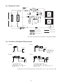
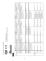
[3] Function of switches and connectors (outdoor unit)
(1) Function of switches
1) Function of switches
(Normal mode)
Kind of
switch
Switch
SW1
CN33
When
open
(Normal)
DIP SW
Pole
Function
1
None
2
Abnormality history clear
Normal mode
SW3 = Unrelated
Operation by switch operation
ON
OFF
–
–
Clear
123456
3
ON
OFF
4
ON
OFF
0
123456
Refrigerant system
address setting
5
5
123456
10
SW2
Tact SW
15
SW4
DIP SW
SW5
3
8
123456
ON
OFF
12
4
123456
ON
OFF
9
123456
ON
OFF
13
14
Running or
stopped
See pages 29 to 34.
Mode input register
Trial run
Trial run mode switching
Inlet temp. re-reading
3-phase power source
detection
Register
Operate
Heat
Do
Normal
Stop
Cool
Do not
Do not
Do
3
Cooling only switching
Cooling only
Heat pump
4
Model setting
PUH-P10MYA
PUH-P8MYA
1
2
1
2
When power
turned on
→ Shows that Nos. 3, 4, 5 , and 6 of
SW1 are ON.
Self diagnosis
SW3
DIP SW
7
123456
ON
OFF
123456
ON
OFF
123456
ON
OFF
11
123456
1
2
3
4
5
6
6
2
123456
ON
OFF
123456
ON
OFF
123456
ON
OFF
ON
OFF
6
1
123456
ON
OFF
123456
ON
OFF
ON
OFF
Normal
123456
ON
OFF
Switch effective timing
–
Running or
stopped
stopped
stopped*1
stopped
–
When power
turned on
When power
turned on
2) Switch functions at set mode change
Kind of
switch
DIP SW
Switch
SW1
When
CN33
shorted
(mode
switching)
Pole
1
2
3
4
5
Remarks
6
Function
Set input mode
CN33 = short SW3 = ON*2
Operation by switch operation
ON
OFF
–
None
–
Night mode
Normal mode
12 °C continuous 2 min- 8 °C continuous 2 minDefrosting end switching
utes
utes
Defrosting prohibit time
Fixed
Training
switching
None
–
–
Night mode
Switch effective timing
–
stopped
stopped
stopped
–
*1 Trial run performs trail run processing by input change while stopped. (For details, see the trail run section)
*2 Mode input is entered by SW3 OFF→ON change (___↑). Press and hold down SW3 for about 2 seconds. The set
mode can be registered according to the outdoor unit setting information on page 31.
Note: After changing the mode by CN33 shorting (mode switching), return to the normal mode by opening CN33.
3) Connector function assignment
Type
Connector
Function
Connector
CN31
CN32
CN33
Emergency operation
Function test
DIP switch mode switching
Operation by open/short
short
open
Start
Function mode
Mode switching
–28–
Normal
Normal
Normal
Switch effective timing
At initialization
At initialization
stopped
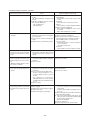
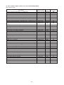
<Outdoor unit operation monitoring function>
The operation status and check code contents can be ascertained by means of the 2-digit number and symbol on digital
display light emitting diode LED2 by operating DIP switch SW2.
<Description of operation of digital display light emitting diode (LED2)>
• When ON (normal operation): Displays the operation mode.
SW2
ON
12 3 4 5 6
ON
OFF
(Load status)
LED2
[Tens digit: Operation mode]
Display
O
C
H
d
[Units digit: Relay output]
Display
0
1
2
3
4
5
6
7
Operation mode
stopped
Cooling/Dry
Heating
Defrost
Compressor
–
–
–
–
ON
ON
ON
ON
4-way valve
–
–
ON
ON
–
–
ON
ON
Bypass solenoid valve
–
ON
–
ON
–
ON
–
ON
• When blinking (Operation stopped by tripping protection device): Displays the check mode
Display
0
1
2
3
4
Check unit
Outdoor unit
Indoor unit 1
Indoor unit 2
Indoor unit 3
Indoor unit 4
Display
E8
E9
EA
Eb
Ed
E0-E7
F8
•
Check contents (at power on)
Indoor-outdoor communication receive abnormal (outdoor unit)
Indoor-outdoor communication send abnormal (outdoor unit)
Indoor/outdoor connection erroneous wiring, number of indoor
units mismatch
Indoor/outdoor connection erroneous wiring (indoor unit power
failure, disconnection)
Serial communication abnormal (M-NET)
Communication other than outdoor unit abnormal
Input circuit faulty
PUH-P8MYA/P10MYA
Display
U2
U3
U4
U6
UE
UL
P1-P8
A0-A8
Check contents (operating)
Compressor discharge temperature abnormal, CN23 short-circuit connector unplugged
Compressor discharge temp thermistor (TH2) open/short
Liquid temp thermistor (TH1), Condenser/evaporater temp thermistor (TH3) open/short
Compressor overcurrent protection trip (51C trip)
High pressure protection (63H1 trip)
Low pressure protection (63L trip)
Indoor unit abnormal
M-NET communication abnormal
–29–
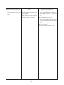
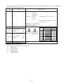
Self diagnosis by SW2
• PUH-P8MYA/P10MYA
SW2 setting
1 2 3 4 5 6
ON
OFF
1 2 3 4 5 6
Display contents
Liquid temperature
(TH1)
–39 - 88
Discharge temperature (TH2)
0 - 216
ON
OFF
FAN output
0 - 100
1 2 3 4 5 6
ON
OFF
1 2 3 4 5 6
Number of compressor
ON/OFF
0 - 999
ON
OFF
1 2 3 4 5 6
ON
OFF
Compressor integrated operation time
0 - 999
Current check mode
code 1
1 2 3 4 5 6
ON
OFF
Description of display
–39 - 88
(When 0 °C or lower, “–”and temperature are displayed
alternately.)
<Example> When –10,
every other second
– ←→ 10
°C
0 - 216
(When 100 or higher, 100s digit and 10s and units digits
are displayed alternately.)
<Example> When 115,
every other second
1 ←→ 15
°C
0 - 100
(When 100 or higher, 100s digit and 10s and units digits
are displayed alternately.)
<Example> When 100,
every other second
1 ←→ 00
%
0 - 999
(When 100 or higher, 100s digit and 10s and units digits
are displayed alternately.)
<Example> When 425,
every other second
4 ←→ 25
100 times
0 - 999
(When 100 or higher, 100s digit and 10s and units digits
are displayed alternately.)
<Example> When 245,
every other second
2 ←→ 45
10 hours
Check mode segment display
method
Segment and bit correspondence
bit 2
Current check mode
code 2
bit 3
bit 4
Check mode 2 display method
bit 5
bit 8
bit 1 ..... Overcurrent trip (Comp)
bit 2 ..... Low pressure protection
bit 6
1 2 3 4 5 6
ON
OFF
LEV opening angle
(/5)
0 - 400
Check mode 1 display method
bit 1 ..... Compressor discharge temperature
abnormal
bit 2 ..... Compressor discharge temp thermistor
abnormal (TH2)
bit 3 ..... CN23 short-circuit connector unplugged
bit 5 ..... Liquid temp thermistor abnormal (TH1)
bit 1
1 2 3 4 5 6
ON
OFF
Unit
bit 7
0 - 400
(When 100 or higher, 100s digit and 10s and units digits
are displayed alternately.)
<Example> When 200 ,
every other second
2 ←→ 00
–30–
5 pulses
Description of display
SW2 setting
Display contents
When no check mode,“00”
<Example> When piping thermistor abnormal U4
1 2 3 4 5 6
Newest check code
Newest outdoor unit
abnormality
Check display
Operation mode when
abnormality occurred
Operation mode when abnormally stopped
<Example> Comp. only ON at cooling operation C4
ON
OFF
1 2 3 4 5 6
Code display
ON
OFF
Code display
ON
OFF
Liquid temperature
(TH1) when abnormality occurred
– 39 - 88
–39 - 88
(When 0 °C or lower, “–” and temperature are displayed
alternately.)
<Example> When –15,
every other second
– ←→ 15
ON
OFF
COMP discharge
temperature (TH2)
when abnormality
occurred
0 - 216
0 - 216
(When 100 or higher, 100s digit and 10s and units digits
are displayed alternately.)
<Example> When 130,
every other second
1 ←→ 30
Check code history (1)
(newest)
Abnormal unit No. and
check code inverted
display
When no abnormality history
“0”, “←→”, “–”
Check code history (2)
(One before newest)
Abnormal unit No. and
check code inverted
display
When no abnormality history
“0”, “←→”, “–”
Current thermostat
ON time
0 - 999
0 - 999
(When 100 or higher, 100s digit and 10s and units digits
are displayed alternately.)
<Example> When 245,
every other second
2 ←→ 45
1 2 3 4 5 6
1 2 3 4 5 6
1 2 3 4 5 6
ON
OFF
1 2 3 4 5 6
ON
OFF
1 2 3 4 5 6
ON
OFF
1 2 3 4 5 6
ON
OFF
Unit
Number of indoor
units connected
0-4
°C
°C
Code display
Code display
Minutes
0-4
Units
–31–
Display contents
Outdoor unit set
information 1
1 2 3 4 5 6
ON
OFF
Outdoor unit set
information 2
1 2 3 4 5 6
Unit
Outdoor unit capacity is displayed as function code.
Model name
function code
PUH-P8MYA
PUH-P10MYA
20
25
Units digit
ON
OFF
Description of display
Tens digit
SW2 setting
Outdoor unit set information 1
3-phase power source detection
Cooling only switching
Night mode
Defrosting end time
Defrosting prohibit time
Code display
Function setting (display valves)
Do
(1) Do not
(0)
Cooling only
(2) H/P
(0)
Night mode
(1) Normal mode
(0)
12 °C continuous 2 minutes (2) 8 °C continuous 2 minutes (0)
Fixed
(4) Training
(0)
Code display
Set information display values are added and displayed at each position.
1 2 3 4 5 6
ON
OFF
1 2 3 4 5 6
ON
OFF
1 2 3 4 5 6
ON
OFF
1 2 3 4 5 6
ON
OFF
1 2 3 4 5 6
Indoor unit piping
temperature (TH2)
Indoor 1
–39 - 88
–39 - 88
(When 0 °C or lower, “–”and temperature are displayed
alternately.)
When there are no indoor units, “00” is displayed.
°C
Indoor unit piping
temperature (TH2)
Indoor 2
–39 - 88
–39 - 88
(When 0 °C or lower, “–”and temperature are displayed
alternately.)
When there are no indoor units, “00” is displayed.
°C
Indoor unit piping
temperature (TH2)
Indoor 3
–39 - 88
–39 - 88
(When 0 °C or lower, “–”and temperature are displayed
alternately.)
When there are no indoor units, “00” is displayed.
°C
Indoor unit piping
temperature (TH2)
Indoor 4
–39 - 88
–39 - 88
(When 0 °C or lower, “–”and temperature are displayed
alternately.)
When there are no indoor units, “00” is displayed.
°C
Indoor intake temperature
8 - 39.5
8 - 39.5
When there are no indoor units, “00” is displayed.
ON
OFF
°C
Indoor set temperature
17 - 30
17 - 30
When there are no indoor units, “00” is displayed.
1 2 3 4 5 6
ON
OFF
°C
–32–
SW2 setting
1 2 3 4 5 6
ON
OFF
Display contents
Indoor unit control
status
Indoor 1, 2
Description of display
Control mode display system
–
Indoor unit No.2
Indoor unit No.4
Indoor unit No.1
Indoor unit No.3
Display
1 2 3 4 5 6
0
1
2
3
4
5
6
7
Indoor unit control
status
Indoor 3, 4
ON
OFF
Condenser/evaporater
temperature (TH3)
1 2 3 4 5 6
ON
OFF
Outdoor unit control
status
Display
0
1
2
3
4
5
6
7
1 2 3 4 5 6
ON
OFF
1 2 3 4 5 6
°C
Indoor unit No.1
Indoor unit No.3 Outdoor unit
1 2 3 4 5 6
1 2 3 4 5 6
–
Control mode display system
ON
OFF
ON
OFF
Control mode
Indoor unit
Outdoor unit
Ordinary
←
Hot adjustment
←
Defrosting
←
—
←
Heater ON
←
Freeze prevention
←
Surge prevention
←
Compressor OFF
←
–39 - 88
(When 0 °C or lower, “–”and temperature are displayed
alternately.)
<Example> When –10,
every other second
– ←→ –10
Indoor unit No.2
Indoor unit No.4
ON
OFF
Unit
Control mode
Indoor unit
Outdoor unit
Ordinary
←
Hot adjustment
←
Defrosting
←
—
←
Heater ON
←
Freeze prevention
←
Surge prevention
←
Compressor OFF
←
Discharge super heat
SHd
0 - 216
Cooling: Outdoor TH2 Outdoor TH3
Heating: Outdoor TH2
- Indoor TH3
(Average)
0 - 216
(When 100 or higher, 100s digit and 10s and units digits
are displayed alternately.)
<Example> When 150,
every other second
1 ←→ 50
Sub cool Sc
0 - 130
Cooling: Outdoor TH3
- Outdoor
TH1
Heating: Indoor TH3
(Average) Indoor TH2
(Average)
0 - 130
(When 100 or higher, 100s digit and 10s and units digits
are displayed alternately.)
<Example> When 100,
every other second
1 ←→ 00
Target sub cool step N
1-5
1-5
–
°C
°C
–
–33–
SW2 setting
1 2 3 4 5 6
ON
OFF
1 2 3 4 5 6
ON
OFF
1 2 3 4 5 6
ON
OFF
1 2 3 4 5 6
ON
OFF
1 2 3 4 5 6
ON
OFF
1 2 3 4 5 6
ON
OFF
1 2 3 4 5 6
ON
OFF
Display contents
Description of display
Unit
Communication demand capacity
0 - 255
0 - 255
When communication demand not set: 100%
(When 100 or higher, 100s digit and 10s and units digits
are displayed alternately.)
<Example> When 100,
every other second
1 ←→ 100
%
Abnormal thermistor
display
1 - 3, –
1 - 3, –
1: Outdoor liquid temp thermistor (TH1)
2: Outdoor discharge temp thermistor (TH2)
3: Outdoor condenser/evaporater temp thermistor (TH3)
–: No abnormal thermistor
FAN output at abnormal stop
0 - 100
0 - 100
(When 100 or higher, 100s digit and 10s and units digits
are displayed alternately.)
<Example> When 100,
every other second
– ←→ 00
LEV opening angle (/5)
at abnormal stop
0 - 400
0 - 400
(When 100 or higher, 100s digit and 10s and units digits
are displayed alternately.)
<Example> When 200,
every other second
2 ←→ 00
Outdoor Condenser/
evaporater temp temperature at abnormal
stop
–39 - 88
–39 - 88
(When 0 °C or lower, “–”and temperature are displayed
alternately.)
<Example> When –10,
every other second
– ←→ –10
Discharge super heat
SHd at abnormal stop
0 - 216
Cooling: Outdoor TH2Outdoor TH3
Heating: Outdoor TH2Indoor TH3
(average)
0 - 216
(When 100 °C or higher, 100s digit and 10s and units
digits are displayed alternately.)
<Example> When 150,
every other second
– ←→ 50
Sub cool Sc at abnormal stop
0 - 130
Cooling: Outdoor TH3Outdoor TH1
Heating: I n d o o r T H 3
(average) -Indoor TH2 (average)
0 - 130
(When 100 °C or higher, 100s digit and 10s and units
digits are displayed alternately.)
<Example> When 100,
every other second
1 ←→ 00
–34–
–
%
5 pulses
°C
°C
°C
SW2 setting
1 2 3 4 5 6
ON
OFF
1 2 3 4 5 6
Description of display
Display contents
Thermostat ON time up
to abnormal stop
0 - 999
0 - 999
(When 100 or higher, 100s digit and 10s and units digits
are displayed alternately.)
<Example> When 245,
every other second
2 ←→ 45
LEV regular control
count n
1-5
1-5
ON
OFF
Minutes
–
1 2 3 4 5 6
ON
OFF
1 2 3 4 5 6
ON
OFF
1 2 3 4 5 6
ON
OFF
1 2 3 4 5 6
ON
OFF
Unit
Indoor unit condenser/
evaporater temp temperature (TH3)
Indoor 1
–39 - 88
–39 - 88
(When 0 ˚C or lower, “–”and temperature are displayed
alternately.)
When there are no indoor units, “00” is displayed.
˚C
Indoor unit condenser/
evaporater temp temperature (TH3)
Indoor 2
–39 - 88
–39 - 88
(When 0 ˚C or lower, “–”and temperature are displayed
alternately.)
When there are no indoor units, “00” is displayed.
˚C
Indoor unit condenser/
evaporater temp temperature (TH3)
Indoor 3
–39 - 88
–39 - 88
(When 0 ˚C or lower, “–”and temperature are displayed
alternately.)
When there are no indoor units, “00” is displayed.
˚C
Indoor unit condenser/
evaporater temp temperature (TH3)
Indoor 4
–39 - 88
–39 - 88
(When 0 ˚C or lower, “–”and temperature are displayed
alternately.)
When there are no indoor units, “00” is displayed.
˚C
–35–
[4] Simple parts check method
• PUH-P8MYA/P10MYA
Part name
Judgment instructions
Thermistor (TH1) <Liquid
temperature detection>
Thermistor (TH2)
<Discharge temperature
detection>
Thermistor (TH3) <Condenser/
evaporater temperature
detection>
Disconnect the connector and measure the resistance value with a multimeter.
(Ambient temperature 10 ˚C to 30 ˚C)
Fan motor
Measure the resistance value across the terminals with a multimeter. (Winding
temperature 20 ˚C)
Red
Thermal protector
trip temperature
135 ±5˚C : ON
88 ±5˚C : OFF
TH1, 3
TH2
Normal
Abnormal
4.3 kΩ~9.6 kΩ
Open or short
160 kΩ~410 kΩ
(Based on thermistor characteristic table (next page))
Motor lead wire
Between 2 phases
Normal
45.5 Ω
Abnormal
Open or short
Black
White
Blue
Compressor
Measure the resistance value across the terminals with a multimeter. (Winding
temperature 20 ˚C)
Normal
PUH-P8MYA
Each phase 1.574 Ω
PUH-P10MYA
Each phase 1.263 Ω
–36–
Abnormal
Open or short
Open or short
[5] Reference Data
<Thermistor characteristic table>
Low temperature thermistor
Thermistor <Liquid temperature detection> (TH1)
Thermistor <Condenser/evaporater temperature detection> (TH3)
Thermistor <Liquid temperature detection> (TH1)
Thermistor <Condenser/evaporater temperature detection> (TH3)
Thermistor Ro = 15 kΩ ± 3 %
B constant = 3,460 kΩ ± 2 %
1
273 + t
<Low temperature thermistor>
50
1
273
Rt = 15 exp {3,460 (–––––– – ––––)}
15 kΩ
9.7 kΩ
6.4 kΩ
5.3 kΩ
4.3 kΩ
3.1 kΩ
40
Resistance
0 °C:
10 °C:
20 °C:
25 °C:
30 °C:
40 °C:
30
20
10
0
-20 -10
0
10
20
30
40
50
60
Temperature
High temperature thermistor
Thermistor <Discharge temperature detection> (TH2)
Thermistor (Discharge temperature detection) (TH2)
Thermistor R120 = 7.465 kΩ ± 2 %
B constant = 4,057 kΩ ± 2 %
1
273 + t
<High temperature thermistor>
25
1
393
Rt = 7.465 exp {4,057 (–––––– – ––––)}
70 °C: 34 kΩ
80 °C: 24 kΩ
90 °C: 17.5 kΩ
100 °C: 13.0 kΩ
110 °C: 9.8 kΩ
20
Resistance
20 °C: 250 kΩ
30 °C: 160 kΩ
40 °C: 104 kΩ
50 °C: 70 kΩ
60 °C: 48 kΩ
15
10
5
0
90
100
Temperature
–37–
110
120
[6] Troubleshooting of each part
(1) LEV
1) Overview of LEV operation
LEV (electronic expansion valve) receives pulse signals from the outdoor unit main circuit board and drives a valve
by means of a servomotor.
The valve opening angle changes in proportion to the number of pulses.
<Outdoor controller board and LEV>
Blue
Brown
Brown
Red
Yellow
Blue
Drive circuit
Yellow
White Red Orange
White
Connector
Outdoor controller board CN40
Output (phase)
No.
ø1
ø2
ø3
ø4
1
ON
ON
OFF
OFF
Output state
2
3
OFF
OFF
ON
OFF
ON
ON
OFF
ON
4
ON
OFF
OFF
ON
<Pulse signal output and valve operation>
The output pulses change in the following order:
Valve closing
1→2→3→4→1
Valve opening
4→3→2→1→4
*1. When the LEV opening angle is not changed, all output
phases turn OFF.
2. When the output misses a phase or remains ON, the motor cannot rotate smoothly and makes a clacking sound
and vibrates.
LEV opening and closing operations
*
D
C
When the power is turned on, to register the valve position, a 2200 pulses valve close signal is output and is always set to point A .
Valve opening angle (flow)
If the valve moves smoothly, the LEV will not generate a sound
or vibration, but at E → A and when the valve is locked, a
sound louder than the sound generated by missing phase,
etc. will be generated.
Valve closing
Valve opening
A
*
Full open
2000 pulses
E
B
Pulse count
Increased throttling region (80 - 100 pulses)
–38–
Generation of sound can be checked by placing the tip of
a screwdriver against the valve and your ear against the
handle.
2) Judgment method and probable trouble mode
Trouble mode
Judgment method
(1) Disconnect the control circuit board connector, and connect the check LED shown below.
When drive circuit is faulty, replace control circuit board.
Microcomputer drive circuit faulty
LEV mechanism locked
LEV motor coil open or
shorted
Connector connection incorrect, or contact faulty
Remedy
When the mains power is turned on, a pulse signal is output for 10 seconds.
If the LED remains OFF or ON, the drive circuit is abnormal.
(1) When the LEV is in the locked state and driven, the motor races. At this time, a soft clicking sound is generated.
When this sound is generated both when closing and
when opening, the mechanism is abnormal.
Measure the resistance between the coils (red-white, redorange, brown-yellow, brown-blue) with a multimeter.
If 150 Ω ±10%, the coil is normal.
(1) Visually check for loose connector terminals and check
the color of the lead wires.
(2) Disconnect the control circuit board connector and
check the continuity with a multimeter.
3) Electronic expansion valve motor replacement instructions
1. Description of construction
1.1 A lock nut connects the motor to the valve body.
1.2 The motor consists of a motor rotating section, rotation
transmission gear section, and a driver which converts
rotation to linear motion.
1.3 The valve body consists of a valve assembly, which
moves up and down, and an orifice.
A bellows at the top of the valve body block isolates the
refrigerant circuit from the atmosphere side.
Therefore, the motor is not exposed to the refrigerant.
Replace LEV
Replace LEV coil
Check continuity of faulty point
Motor
Driver
Bellows
Refrigerant
circuit
Lock nut
Valve assembly
Valve body
Orifice
2. Principle of operation
2.1 Pulses output from the control circuit board are sequentially supplied to four coils and the motor is rotated.
The motor can be rotated in either clockwise or counterclockwise by changing the order in which the pulses are
supplied.
2.2 The gear section reduces the motor speed to 1/30 and supplies the motor rotation to the motor output shaft.
2.3 The motor output shaft is threaded and is used as a driver.
2.4 The up and down motion of the end of the driver moves the valve assembly of the valve body up and down and
controls the flow by changing the distance between the orifice and the bottom end of the valve.
–39–
3. Work precautions
3.1 Do not apply abnormal force to the motor.
3.2 Do not use a motor that has been dropped.
3.3 Do not remove the cap until immediately before starting work.
3.4 Do not wipe off the molybdenum.
3.5 Do not remove the packing.
3.6 Do not coat the lock nut with a substance other than
the specified lock tight, grease, etc.
Motor
Packing
Molybdenum
Cap
4. Replacement instructions
4.1 Stop the air conditioner from the remote controller. After confirming that the air conditioner has stopped, turn off
the outdoor unit power.
4.2 Get two wrenches. Hold the flat part of the body with one wrench and loosen the lock nut with the other wrench.
The lock nut loosens when turned counterclockwise as viewed from the motor.
Always use two wrenches.
Do not hold the motor with one hand and try to loosen the lock nut with only one wrench.
4.3 When the lock nut is turned several turns, it will disengage from the threads and the motor can be removed.
4.4 Get the replacement motor. The replacement motor is limited to a motor whose driver end position has been
set at the factory for replacement use. (The driver end of factory set parts does not stick out.)
Use of a motor whose driver end position is not set is related to erroneous valve flow control or no operation.
4.5 During replacement work, be sure that dirt, foreign matter, or water does not enter the part where the motor
and valve body separate.
(Since the part exposed by separation corresponds to the mechanical part of the valve.) Do not damage the
connecting part with the tools. After removing the motor, 1 blow out the body bellows section with N2 gas, etc.
to remove the water clinging to the inside and 2 after fan stop processing of the pertinent unit in the motor
removed state, dry the bellows section by performing the cooling operation for 30 minutes.
4.6 Remove the cap of the replacement motor and butt the bottom of the motor against the top of the valve body
and hold it so that both are aligned and connect the motor to the valve body with the lock nut. Coat the entire
periphery of the threaded part with screw lock. Be sure that the screw lock does not enter the interior.
If a defect occurs during replacement work, do not use the motor, instead use a new replacement motor.
4.7 After tightening the lock nut 2 to 3 turns by hand, hold the flat part of the body with one wrench and tighten to
the prescribed torque with a torque wrench. Tighten to a torque of 15N·m (150kgf·cm) (Control value 15 ±1N·m
(150 ± 10 kgf·cm))
If tightened too tight, the flare nut may break during use.
4.8 When tightening the lock nut, hold the motor with your hand, etc. so that strong rotation torque and bending
load are not applied.
4.9 The difference of the relative positions of the motor and body after assembly has no affect on the valve control
and open/close mechanism.
Do not try to forcefully position the motor and valve body to correct “displacement” after tightening of the lock
nut due to the difference in the positional relationship between the motor and valve body before and after
assembly.
Fixing with the clip may be impossible due to motor section deformation, but fixing of the piping is sufficient and fixing by clip is unnecessary.
4.10 Connect the connector. At this time, be sure not to pull the lead
wires forcefully. Also, firmly insert the connector up to the lock and
check that it cannot not be easily disconnected.
4.11 Turn on the outdoor unit power and operate the air conditioner from
the remote controller and confirm that there are no abnormalities.
–40–
Rotation direction
“displacement” is OK.
[7] Emergency operation
1) When the following check displays occur at the outdoor unit, or when the wired remote controller or indoor unit
microcomputer fails, if there are no other defects, emergency operation is possible by shorting the connector (CN31)
on the outdoor controller board.
• Abnormalities that allow emergency operation
Display
U4
E8
E9
E0 - E7
Check contents
Liquid temp thermistor (TH1) open or shorted
Condenser/evaporater temp thermistor (TH3) open or shorted
Indoor-outdoor communication receive abnormal (outdoor unit)
Indoor-outdoor communication send abnormal (outdoor unit)
Communication other than outdoor unit abnormal
2) Check items and precautions when performing emergency operation
a) In addition to the abnormalities above, check the outdoor unit for any abnormalities. (When there is an abnormality other than the above, emergency operation is impossible.)
b) Check the operating range. (For U4 display)
Since the outdoor fan always operates at full speed at emergency operation, do not operate the air conditioner
outside the range shown below.
Operation outside this range may cause comOperation range (outdoor unit intake temperature)
pressor trouble.
Cooling
geater than 20 °C
Heating
less than 10 °C
c) When performing emergency operation, set the outdoor unit after setting the emergency operation switch (SWE)
on the indoor controller board. For the indoor emergency operation method, refer to the indoor unit wiring
diagram.
d) A power failure causes emergency operation to become continuous operation. ON/OFF, temperature adjustment and other operations cannot be performed from the remote controller.
(When a PEH-P8MYA or P10MYA indoor unit is connected, check that the special indoor unit power is turned
on, then start emergency operation.)
e) Since cool air is discharged from the indoor unit, when the outdoor unit starts the defrosting operation during
heating emergency operation, do not operate the air conditioner for a long time.
f) You can perform cooling emergency operation up to 10 hours. The indoor unit heat exchanger may freeze.
g) At the end of emergency operation, always return the switch settings, etc. to their original state.
3) Emergency operation contents
a) The operation mode operates according to the contents set (cooling or heating) by SW4-2.
b) The fan operation condition is always 100% operation.
c) The operation mode display flashes every other second.
–41–
4) Emergency operation method
* Before starting, recheck that the trouble allows
emergency operation.
Start
NO
Piping work complete?
YES
Check that mains power is OFF
Turn on emergency operation switch
(SWE) on indoor controller board
Short CN31 (emergency operation
connector) on outdoor controller board
Set operation mode (cooling or heating) with SW4-2 on outdoor board
(SW4-1 not used)
SW4
OFF ON
1
Cooling
2
Heating
Turn on indoor power *1
Turn on mains power
Check that emergency operation starts,
and that operation mode display flashes
5)
*1 Only when PEH-P8 or 10 or 16 or 20MYA indoor
unit connected.
Emergency operation release method
a) Turn off mains power. (Outdoor, indoor)
*1
b) Turn off emergency operation switch
(SWE) on indoor controller board
c) Open CN31 (emergency operation
connector) on outdoor controller board
d) Set SW4-2 as shown below
SW4
OFF ON
1
2
*1. When PEH-P8 or 10 or 16 or 20MYA indoor unit
is connected, first turn off the outdoor unit power,
then turn off the indoor unit power.
e) Turn on mains power
–42–
[8] Self-diagnosis and troubleshooting
<Abnormality detected at power on>
Abnormal- Meaning of abnormality display and
ity display abnormality troubleshooting
Cause
(1) Voltage not applied to outdoor unit terminal block TB1.
a. Power supply circuit breaker not
closed.
b. Power supply terminals connection
faulty, or disconnected.
c. Missing phase (R or S phase)
(2) No electricity at controller board power
supply connector.
a. Power supply connector contact
faulty.
b. Terminal R/1 or S/2 on controller
board disconnected.
(3) Outdoor unit controller board faulty.
a. Blown fuse on controller board.
b. Part faulty.
None
EA
Indoor/outdoor connection erroneous wiring, too many indoor
units (5 or more)
1. Outdoor controller board automatically recognizes the number of
connected indoor units. However,
when the number of connected indoor units cannot be set due to erroneous indoor/outdoor connection, erroneous wiring, etc. even
after 4 minutes have elapsed since
the power was turned on, an abnormality is recognized.
2. When the outdoor controller board
identified “5 or more” connected indoor units, an abnormality is recognized.
(1) Indoor/outdoor connection wire contact faulty or erroneous wiring.
(2) Indoor/outdoor connection wire diameter or wiring length outside specification.
(3) Five or more indoor units connected
to outdoor unit.
(4) Outdoor controller board send/receive
circuit faulty.
(5) Indoor controller board send/receive
circuit faulty.
(6) Noise has entered on power supply
or indoor/outdoor connection wire.
Eb
Indoor/outdoor connection erroneous wiring
The outdoor controller board automatically sets the unit No. of the indoor units. However, when the unit
No. of the indoor units cannot be set
due to indoor/outdoor connection erroneous wiring even after 4 minutes
has elapsed since the power was
turned on, an abnormality is recognized.
(1) Indoor/outdoor connection wire contact faulty, or erroneous wiring.
(2) Indoor/outdoor connection wire diameter or wiring length outside specification.
(3) Outdoor controller board send/receive
circuit faulty.
(4) Indoor controller board send/receive
circuit faulty.
(5) Noise has entered on power supply
or indoor/outdoor connection wire.
Start-up time over
When start-up processing does not
end even through 4 minutes has
elapsed since the power was turned
on, an abnormality is recognized.
(1) Indoor/outdoor connection wire contact faulty.
(2) Indoor/outdoor connection wire diameter or wiring length outside specification.
(3) Noise has entered on power supply
or indoor/outdoor connection wire.
F1
Reverse phase detected
Power supply reverse phase connection.
F2
Missing phase detected
Power supply missing phase.
EC
–43–
Judgment method and remedy
(1)
a. Check power supply circuit breaker.
b. Check power supply terminal block
connections.
c. Check power supply terminal block
connections.
(2)
a. Check power supply connector board
connections.
(3)
a. Replace fuse.
b. Replace controller board.
(However, when cannot be repaired
even through the check above was
carried out.)
(1) Check if indoor unit or outdoor unit indoor/outdoor connection wire disconnected or loose. Also check polarity.
(2) Check indoor/outdoor wire diameter
and wiring length.
Outdoor-indoor: Max. 50m
Indoor-indoor (span): Max. 30m
Also check that VVF and other flat
cables are connected in S1, S2, S3 order. (S2 in the middle)
(3) Check number of indoor units connected to outdoor unit.
(4) Check by turning power off and on.
If abnormality is displayed again, replace outdoor controller board or indoor
controller board.
* LED3 of the indoor controller board
flashes when communication is being
performed.
(1) Check power supply terminal block
connections.
(2) Replace controller board
(However, when cannot be repaired
even though check above was carried
out.)
<Abnormality detected during unit operation: Outdoor unit>
Abnormal- Meaning of abnormality display and
ity display abnormality troubleshooting
Cause
Judgment method and remedy
Discharge temperature abnormal
When the discharge thermistor temperature (TH2) exceeds 118 °C while
the compressor is operating, an abnormality is recognized.
(1) Compressor overheating due to insufficient refrigerant.
(1) Check input super heat.
Check for refrigerant leakage and
check piping length.
Charge with additional refrigerant.
(2)(3)
Turn off power and restart operation
and check if U3 is displayed within 8
minutes.
When U3 is displayed, carry out U3 processing.
(Do not replace board at U2 display
only.)
49C trip (CN23 connector disconnected)
When connector CN23 opens while
the compressor is operating, an abnormality is recognized.
(1) Shorting connector CN23 on outdoor
controller board dislodged or contact
faulty.
(1) Repair shorting connector.
Discharge temp thermistor (TH2)
open or shorted.
When an open (0 °C or lower) or
short (216 °C or higher) is detected
while the compressor is operating, an
abnormality is recognized.
(Detection is disabled for 5 minutes
at compressor starting.)
(1) Connector (CN3) dislodged or connect faulty.
(2) Thermistor faulty.
(1) Check connector contact and thermistor wire.
(2) Check thermistor resistance value, or
check temperature by microcomputer.
(Check using SW2 self-diagnosis function.)
See page 36.
(3) Replace outdoor controller board.
(Replace board after sufficiently checking 1 and 2.)
Liquid temp thermistor (TH1) or
condenser/evaporater temp thermistor (TH3) open or shorted.
When an open (–39 °C or lower) or
short (88 °C or higher) is detected
while the compressor is operating, an
abnormality is recognized. (Detection
is disabled for 7 minutes beginning
from 10 seconds after the compressor starts and for 10 minutes after
return from defrosting.)
(1) Connector (TH1: CN2, TH3: CN4) dislodged or contact faulty.
(2) Thermistor faulty.
Compressor overcurrent trip
When the current value reaches the
overload set value or higher while the
compressor is operating, an abnormality is recognized.
P8MYA .................................. 22 A
P10MYA ................................ 27 A
(1) Overload operation exceeding unit usage range limit.
(2) Power supply terminal voltage low.
(3) Power supply missing phase.
(4) Compressor motor faulty.
(5) Compressor locked.
(6) Connector (CN22) on outdoor controller board dislodged or contact faulty.
(7) 51C disconnected or contact faulty.
(1) Check usage conditions.
(Check for short cycle operation.)
(2) Check power supply voltage.
(3) Check wiring for breaks and faulty contact.
(4) Check motor winding resistance (See
page 35.)
(5) Replace compressor.
(6)(7)
After checking connections, restart and
check operation.
High pressure abnormal (63H1
trip)
Detected (3.3+0
-0.15 MPa) by 63H1 trip
while compressor is operating.
(1) Started with ball valve closed.
(2) Connector (CN21) on outdoor controller board dislodged or contact faulty.
(3) 63H1 disconnected or contact faulty.
(4) Indoor filter clogged. Power reset detected during heating overload operation (Heating).
(5) Low indoor unit air flow (heating).
(6) Low outdoor unit air flow (cooling).
(7) Part faulty.
(1) Check if ball valve is fully open.
(2)(3)
Repair connector.
(4) Check indoor filter.
(5) Check flow duct static pressure and for
faulty fan motor.
(6) Check for faulty outdoor fan motor.
(7) Replace pressure switch.
(2) Thermistor faulty. (TH2)
(3) Outdoor controller board faulty.
U2
U3
U4
U6
UE
63H1: Pressure switch (high pressure)
OFF: 3.3 MPa
(3) Outdoor controller board faulty.
(3) Outdoor controller board faulty.
–44–
(1) Check connector contact and thermistor wire.
(2) Check thermistor resistance value or
check temperature by microcomputer.
(Check using SW2 self-diagnosis function.)
See to page 36.
(3) Replace outdoor controller board.
(Replace board after sufficiently checking 1 and 2)
Abnormal- Meaning of abnormality display and
ity display abnormality troubleshooting
Cause
Judgment method and remedy
Low pressure abnormal (63L trip)
Detected by tripping of 63L while the
compressor is operating. (Ignored
during defrosting and for 10 minutes
at defrosting return.)
63L: Pressure switch (low pressure)
OFF: 0 MPa
(1) Started with ball valve closed.
(2) Connector (CN27) on outdoor controller board open or contact faulty.
(3) 63L disconnected or contact faulty.
(4) Part faulty.
(1) Check if ball valve fully open.
(2)(3) Repair connector.
EO
Remote controller communications receive abnormal (remote
controller).
1) When transmission from refrigerant address “0” IC is not received
normally even once in 3 minutes,
an abnormality is recognized.
2) When a slave remote controller
does not receive even one signal
in 2 minutes, an abnormality is
recognized.
(1) Remote controller send/receive
circuit faulty.
(2) Refrigerant address “0” indoor controller board send/receive circuit faulty.
(3) Noise entered on remote controller
transmission line.
(1) Remote controller send/receive circuit
faulty.
(2) Noise entered on remote controller
transmission line.
E3
Remote controller communication
send abnormal (remote controller)
1) When the remote controller can
not confirm that the transmission
circuit is idle in 6 seconds, an abnormality is recognized.
2) When the remote controller cannot complete 30 continuous transmissions, an abnormality is recognized.
Perform remote controller diagnosis.
Take the following action based on the diagnosed result:
a) [RC OK] display
Remote controller normal.
Turn power off and on and check.
If “H0” remains on for 4 minutes or
longer, replace indoor controller board.
b) [RC NG] display
Replace remote controller.
c) [RC E3] display Noise, etc. probable
[ERC00-66]
cause.
Indoor-outdoor communication
receive abnormal
(Outdoor unit)
When the outdoor controller can
not receive normally even once in
3 minutes, an abnormality is recognized.
(1) Indoor/outdoor connection wire contact faulty.
(2) Outdoor controller board send/receive
circuit faulty.
(3) Indoor controller board send/receive
circuit faulty.
(4) Noise entered on indoor/outdoor connection wire.
(1) Check for disconnected or loose indoor
unit or outdoor unit indoor/outdoor connection wire.
(2)-(4)
Turn power off and on and check.
If abnormality displayed again, replace
indoor controller board or outdoor controller board.
Indoor-outdoor communication
send abnormal
(Outdoor unit)
1) When the outdoor controller
detectes reception of 30 consecutive “0” even through “1” was received, an abnormality is recognized.
2) When the outdoor controller can
not confirm that the transmission
circuit is idle in 3 minutes, an error is recognized.
(1) Outdoor controller board send/receive
circuit faulty.
(2) Noise entered at power supply.
(3) Noise entered on indoor/outdoor connection wire.
(1)(2)(3)
Turn power off and on and check.
If abnormality displayed again, replace
indoor controller board or outdoor controller board.
Check code undefined
Displayed when an undefined check
code is received.
(1) Noise entered on remote controller
transmission line.
(2) Noise entered on indoor/outdoor connection wire.
(1)(2)
Turn power off and on and check.
If abnormality displayed again, replace
indoor controller board or outdoor controller board.
UL
E8
E9
EF
–45–
(4) Replace pressure switch.
<Abnormality detected during unit operation: Indoor unit>
Abnormal- Meaning of abnormality display and
ity display abnormality troubleshooting
P1
P2
P4
Cause
Judgment method and remedy
Intake sensor abnormal
1) If thermistor open or short is detected and the compressor enters
the 3 minutes restart prevention
mode and does not return to normal after 3 minutes, an abnormality is recognized.
(If returned, returns to normal operation.)
2) Always detected during cool, dry,
and heat operations.
Short: 90 °C or higher
Open: –40 °C or lower
(1) Thermistor characteristics faulty.
(2) Connector contact faulty.
(Insertion faulty)
(3) Thermistor wiring open or contact
faulty.
(4) Indoor controller board faulty.
(1)-(3)
Check thermistor resistance value
0 °C ...... 15.0 kΩ
10 °C ........ 9.7 kΩ
20 °C ........ 6.4 kΩ
30 °C ........ 5.3 kΩ
40 °C ........ 3.1 kΩ
Open or faulty contact can be detected
by applying force (pulling, bending) to
lead wire while measuring thermistor
resistance.
(2) Check for connector faulty contact.
After reinserting connector, turn on
power and recheck operation.
(4) Check remote controller room temperature display.
If there is a difference between actual
room temperature and displayed room
temperature after checking that there
are no problems at (1)-(3), replace indoor controller board.
If there are no problems above, there
are no abnormalities.
Turn power off and on and operate.
Piping sensor abnormal
1) If thermistor short or open is detected and the compressor enters
the 3 minutes restart prevention
mode and does not return to normal after 3 minutes, an abnormality is recognized.
(If returned, returns to normal operation.)
2) Always detected during cool, dry,
and heat (except during defrosting) operation.
Short: 90 °C or higher
Open: –40 °C or lower
(1) Thermistor characteristics faulty.
(2) Connector contact faulty.
(Insertion faulty)
(3) Thermistor wiring open or contact
faulty.
(4) Faulty refrigerant circuit, etc. has
caused thermistor temperature to rise
to 90 °C or higher or drop to –40 °C
or lower.
(5) Indoor controller board faulty.
(1)-(3)
Check thermistor resistance value.
For characteristic, see above (P1).
(2) Check for connector faulty contact.
After reinserting connector, turn on
power and recheck operation.
(4) Operate in trail run mode and check
piping temperature with remote controller. When piping temperature is abnormally low (cooling) or high (heating),
refrigerant circuit is probably faulty.
(5) Check test run mode piping temperature with remote controller.
If there is a difference between actual
piping temperature and displayed piping temperature when there are no abnormalities at (1)-(4), replace indoor
controller board. If there is no problem
above, there are no abnormalities.
Turn on power and operate.
Drain sensor abnormal
1) If thermistor short or open continuously detected for 30 seconds, the
compressor enters the check
mode and turns off and the indoor
fan turns off.
2) When another short or open is
continuously detected for 30 seconds in the check mode, an abnormality is recognized.
(If returned, returns to normal operation.)
3) Always detected during cool, dry,
and drain pump operation.
Short: 90 °C or higher
Open: –20 °C or lower
(1) Thermistor characteristics faulty.
(2) Connector contact faulty.
(Insertion faulty)
(3) Drain sensor wiring open or contact
faulty.
(4) Indoor controller board faulty.
(1)-(3)
Check thermistor resistance value.
0 °C .... 6.0 kΩ
10 °C .... 3.9 kΩ
20 °C .... 2.6 kΩ
30 °C .... 1.8 kΩ
40 °C .... 1.3 kΩ
(2) Check connector for faulty contact.
After reinserting connector, turn on
power and recheck operation.
(4) If abnormality reproduced by shorting
between drain sensor connector CN31
pins 1 and 2 and operating air conditioner, replace indoor controller board.
If there are no problems above, there
are no abnormalities.
Turn on power and operate.
–46–
<Abnormality detected during unit operation: Indoor unit>
Abnormal- Meaning of abnormality display and
ity display abnormality troubleshooting
P5
P6
Cause
Judgment method and remedy
Drain overflow protection operation
1) When the drain sensor thermistor
overheats and the temperature
rise is small, the compressor enters the check mode and is turned
off and the indoor fan is turned off.
2) If the state above is detected again
in the check mode, drain pump
abnormality is recognized.
3) Always detected during drain
pump operation.
(1) Drain pump trouble.
(2) Drain faulty.
Drain pump clogged.
Drain pipe clogged.
(3) Water droplets on drain sensor.
Drain water waves created by transmission of drain water from lead wire,
clogged filter, etc.
(4) Indoor controller board faulty.
(1) Check drain up mechanism.
(2) Check drain characteristic.
(3) Check drain sensor lead wire arrangement and check for filter clogging.
(4) If abnormality reproduced by shorting
between drain sensor connector CN31
pins 1 and 2 and operating air conditioner, replace indoor controller board.
If there are no problems above, there
are no abnormalities.
Turn on the power and operate.
Water leakage abnormality (PDH
only)
1) When the drain sensor thermistor
overheats and the temperature
rise is small, the compressor enters the check mode and the drain
pump is turned on for 6 minutes.
(Detection: 1 time/hour)
2) If the state above is detected
again within 12 hours after the
check mode was entered, a water leakage abnormality is recognized.
3) Detected during stop, fan, and
heat operation.
(1) Water leaking from humidifier water
supply pipe.
(2) Water droplets on drain sensor.
(3) Indoor controller board faulty.
(1) Repair water leakage.
(2) Check drain sensor lead wire arrangement and check for filter clogging.
(3) If abnormality reproduced by shorting
between drain sensor connector CN31
pins 1 and 2 and operating air conditioner, replace indoor controller board.
If there are no problems above, there
are no abnormalities.
Turn on power and operate.
Freezing/excessive rise protection
operation
1) Freezing protection
When the piping temperature remains at –15 °C or lower for 3 minutes after 3 minutes have elapsed
since the compressor started, the
compressor enters the 6 minutes
restart prohibit mode and if the
piping temperature again remains
at –15 °C for 3 minutes within 16
minutes after 6 minutes restarting,
an abnormality is recognized.
2) Excessive rise protection
When a piping temperature rise
to 70 °C or higher is detected after the compressor starts, the
compressor enters the 6 minutes
restart prohibit mode. If a piping
temperature rise up to 70 °C or
higher is detected again within 10
minutes after 6 minutes restarting,
an abnormality is recognized.
<Cool and dry>
(1) Filter is clogged (insufficient air flow).
(2) Air duct short cycle.
(3) Low load operation (low temperature)
exceeding allowable range.
(4) Indoor fan motor faulty.
(5) Outdoor fan control faulty (intermediate period, winter).
(6) Refrigerant overcharged.
(7) Refrigerant circuit faulty (clogged).
<Cool and dry>
(1) Check filter for clogging.
(2) Remove obstruction.
(4) Check fan motor operation and winding resistance.
(5) Check outdoor fan motor operation.
(6)(7)
Check refrigerant circuit operation.
<Heat>
(1) Filter clogged (insufficient air flow)
(2) Air duct short cycle.
(3) Overload operation (high temperature) exceeding allowable range.
(4) Indoor fan motor faulty.
(5) Outdoor fan control faulty (intermediate period)
(6) Refrigerant overcharged.
(7) Refrigerant circuit faulty (clogged)
(8) Outdoor unit bypass circuit faulty.
–47–
<Heat>
(1) Check filter for clogging.
(2) Remove obstruction.
(4) Check fan motor operation and winding resistance.
(5) Check outdoor fan motor operation.
(6)-(8)
Check refrigerant circuit operation.
<Abnormality detected during unit operation: Indoor unit>
Abnormal- Meaning of abnormality display and
ity display abnormality troubleshooting
P8
E4
Cause
Judgment method and remedy
Piping temperature abnormal
<Cool>
When the piping temperature stays
outside the cooling area for 1 minute
after 3 minutes have elapsed since
the compressor was started, the indoor fan operates at low speed. If the
piping temperature does not return
to the cooling area after 5 minutes
operation at low speed, an abnormality is recognized.
Note 1) It takes a minimum of 9 minutes for an abnormality to be
detected.
Note 2) At dry operation, P8 abnormality is not detected.
<Heat>
When the piping temperature falls
outside the heating area and enters
the ventilation area after compressor
operation and the end of hot adjust,
the indoor fan stops and the piping
temperature does not return to the
heating area within 20 minutes after
10 seconds have elapsed after it left
the heating area, an abnormality is
recognized.
Note 3) It takes a minimum of 22
minutes and a maximum of
27 minutes for an abnormality to be detected.
Note 4) Except during defrosting
(Detected again after defrosting return.)
(1) Indoor intake piping thermistor temperature differential small.
- EInsufficient refrigerant
- EPiping thermistor holder dislodged.
- ERefrigerant circuit faulty.
(2) Extension piping (When multiple units
connected).
(3) Indoor/outdoor connection wire
(When multiple units connected).
(4) Indoor intake piping thermistor detection faulty.
(1) Operate in test run mode and check
piping temperature.
(2)(3)
Check extension piping or indoor/outdoor connection wire.
(4) Check remote controller room temperature display and piping temperature in
test run mode.
Remote control communication receive abnormal
1) When the indoor controller board
can not receive data normally
from the remote controller or another indoor controller board even
once in 3 minutes, an abnormality is recognized.
2) When the indoor controller board
can not receive signals even once
in 2 minutes, an abnormality is
recognized.
(1) Remote controller transmission line
contact faulty.
(2) All remote controllers set as “slave”
remote controller.
(3) Remote controller send/receive circuit
faulty.
(4) Indoor controller board send/receive
circuit faulty.
(5) Noise entered on remote controller
transmission line.
(1) Check if indoor unit or remote controller transmission line disconnected or
loose.
(2) Set one remote controller as “master”.
When there are no problems at the
above
(3) Perform remote controller diagnosis.
a) [RC OK] display
Remote controller normal.
Check by turning power off and on.
If the abnormality occurs again, replace
indoor controller board.
b) [RC NG] display
Replace remote controller.
c) [RC E3] display
[ERC00-66] noise, etc. is probable
cause.
–48–
–49–
Normal stoppage
No error occurs, therefore no countermeasures
possible.
Normal boot-up completed.
51F error
Normal stoppage
No error occurs, therefore no countermeasures
possible.
Normal boot-up completed.
No.2 system
error
Normal stoppage
No error occurs, therefore no countermeasures
possible.
Normal boot-up completed.
Refrigerant
No.1 system
Related Errors error
Correct cause of error.
Correct cause of error.
Correct cause of error.
No.1 system error stoppage.
No No.2 system stoppage.
Remote controller indicates error, however,
remote controller operation is not possible other
than at stoppage. (No fan stoppage.)
No No.1 system stoppage.
No.2 system error stoppage.
Remote controller indicates error, however,
remote controller operation is not possible other
than at stoppage. (No fan stoppage.)
No No.1 system stoppage.
No.2 system error stoppage.
Remote controller indicates error, however,
remote controller operation is not possible other
than at stoppage. (Fan stoppage.)
No error occurs, therefore no countermeasures
possible.
No error occurs, therefore no countermeasures
possible.
No error occurs, therefore no countermeasures
possible.
Communication error detected at No.1 and No.2 (1) Repair cable C
system indoor unit due to remote controller
error, and all systems stopped.
(1) Repair cable C
Communication error detected at No.2 system (1) Repair cable C
indoor unit, however, no error reported at
remote controller when D breakage occurs. No.2
system cannot be operated.
(1) Repair cable D
Communication error detected at No.2 system
indoor unit, however, no error reported at
remote controller when D breakage occurs.
Error can be confirmed at outdoor unit LED.
(No.1 system has booted up and therefore
operation is possible.)
Cable D
breakage,
reverse
connection
Recommended Countermeasure
(1) Repair cable A.
[Emergency Repair]
(1) Set to the No.2 address and cut the power to
the No.1 outdoor unit. (single system
operation.) Change No.1 address to 01.
Error occurred at both No.2 system outdoor and (1) Repair cable B.
indoor unit and error occurs at remote controller. [Emergency Repair]
(1) Cut power to outdoor unit No.2.
Operation can be continued as no error has
Single system operation.
occurred at system No.1, however, remote
controller operation is not possible other than at
stoppage. (No fan stoppage.)
The outdoor unit for address 00 is no longer
connected to the system, and operation is not
possible as there is no power supply to the
remote controller, resulting in an error.
During Operation
Error Details
Communication error detected at No.2 system
indoor unit, however, no error reported at
remote controller when D breakage occurs.
Communication error detected at No.2 system
indoor unit, resulting in stoppage.
Communication error detected at No.1 and No.2 (1) Repair cable C
system indoor unit due to remote controller
error, however, no error reported at remote
controller as inoperable during stoppage.
(1) Repair cable C
No power to remote controller and so
inoperable.
Error can be confirmed at outdoor unit LED.
(1) Repair cable B.
[Emergency Repair]
(1) Cut power to outdoor unit No.2.
Single system operation.
(1) Repair cable A.
[Emergency Repair]
(1) Set to the No.2 address 00 and cut the power
to the No.1 outdoor unit. (single system
operation.) Change No.1 address to 01.
Cable C
breakage,
reverse
connection
Error detected at both No.2 outdoor and indoor
unit, however, the remote controller cannot be
used during the stoppage, and therefore no
error is indicated.
The outdoor unit for address 00 is no longer
connected to the system, and operation is not
possible as there is no power supply to the
remote controller, resulting in an error.
Recommended Countermeasure
(1) Repair cable B.
Unable to boot up system No.2 and error
[Emergency Repair]
detected at both the outdoor and indoor unit,
however, the remote controller cannot be used (1) Cut power to outdoor unit No.2.
Single system operation.
during the stoppage, and therefore no error is
indicated. Error can be confirmed at outdoor unit
LED.
(No.1 system has booted up and therefore
operation is possible.)
(1) Repair cable A.
[Emergency Repair]
(1) Set to the No.2 address 00 and cut the power
to the No.1 outdoor unit. (single system
operation.) Change No.1 address to 01.
The outdoor unit for address 00 is no longer
connected to the system, and operation is not
possible as there is no power supply to the
remote controller. Error can be confirmed at
outdoor unit LED.
Stoppage (power supplied)
Error Details
Cable B
breakage,
reverse
connection
Recommended Countermeasure
D
A : No. 1 system indoor/outdoor unit transmission cable.
B : No. 2 system indoor/outdoor unit transmission cable.
C : Remote controller cable for board No.1 (communication of operation and control details).
D : Cable connecting No.1 and No.2 board (communication of operation and control details)
Prior to power ON to boot-up
Error Details
No.2 board
Indoor unit
No.1 board
Wiring Errors Cable A
breakage,
reverse
connection
Remote controller
C
B
Outdoor unit No.2
Address: 01
A
Outdoor unit No.1
Address: 00
* Error countermeasures for PEH-P16·20MYA
<Troubleshooting and repair by symptom>
Symptom and operation when normal
Cause
Symptom judgment and remedy
1. No remote controller display
(1) DC14V is not supplied to remote con- (1) Check LED2 on indoor controller board.
troller.
1) Steady light
(No power O display on liquid crystal
Check remote controller wire open or faulty
panel.)
contact.
(2) DC14V is supplied to remote controller
2) Flashing
but nothing is displayed.
Check for remote controller wire short.
- “H0” not displayed
3) Not lit
- “H0” displayed
Check outdoor controller refrigerant address.
(2) Make the following judgment:
- When “H0” is not displayed, remote controller is faulty.
- When “H0” is displayed, see item 2.
2. Remote controller displays “H0” unchanged.
(1) Remote controller displays “H0” for
maximum of 2 minutes for starting after
power turned on.
(2) Indoor-remote controller communication
faulty.
(3) Outdoor-indoor communication faulty.
(1) Normal operation.
(2) Remote controller self-diagnosis.
(3) When outdoor-indoor cannot communicate
“H0” is displayed for a maximum 6 minutes.
Check LED3 on indoor controller board.
1) Does not flash
Check indoor/outdoor connection cable for
erroneous wiring.
(S1 and S2 or S3 open)
2) Flashes
Indoor/outdoor connection cable is normal.
3. When remote controller operation
switch pressed, operation display
appears but immediately disappears.
(1) Operation switch is disabled for approximately 30 seconds after function select
operation from remote controller is released.
(1) Normal operation.
4. Does not beep and air conditioner
does not operate even when operated with wireless remote controller.
(Operation display appears on wireless remote controller.)
(1) Wireless remote controller and indoor
controller board pair number setting mismatched.
(2) Cause of item 1.
(1) Check pair number setting.
(2) Item check of item 1.
5. When operated with wireless remote controller, beeps but does not
operate.
(1) Air conditioner does not operate for a
maximum of 2 minutes after the power
is turned on.
(2) Set to local operation prohibit mode.
- Remote start/stop adapter is connected to CN32 on indoor controller
board.
- Air conditioner is connected to
MELANS and is set to local operation
prohibit mode from centralized controller, etc.
(3) Cause of item 2.
(1) Normal operation.
(2) Normal operation.
(3) Item check of item 2.
6. Remote controller display is normal
and cooling operation is performed,
but without any capacity (does not
cool).
(1) Insufficient refrigerant.
(2) Filter clogged.
(3) Outdoor unit heat exchanger clogged.
(4) Air duct short cycle.
(5) Outdoor unit bypass circuit faulty.
(1) - When there is leakage, discharge temperature rises. Therefore, check by measuring
temperature.
- Check for gas leakage from piping connections, etc.
(2) Open intake grille and check filter. Clean filter,
and remove dust and dirt.
(3) - Since both indoor piping temperature and
outlet pressure rise when filter clogged, judge
by measuring outlet pressure.
- Clean heat exchanger.
(4) Remove obstruction.
(5) Check refrigerant circuit operation state.
–50–
Symptom and operation when normal
Cause
Symptom judgment and remedy
7. Remote controller display is normal
and heating operation is performed
but without any capacity (does not
(1) Insufficient refrigerant.
(2) Refrigerant piping heat insulation insufficient.
(3) Filter clogged.
(4) Indoor unit heat exchanger clogged.
(5) Air duct short cycle.
(6) Outdoor unit bypass circuit faulty.
(1) - Since the discharge temperature rises when
there is leakage, judge by measuring the temperature.
- Check piping connections, etc. for gas leakage.
(2) Check heat insulation.
(3) Open intake grille and check filter.
Clean filter, and remove dust and dirt.
(4) - Since the indoor piping temperature and outlet pressure rise when the heat exchanger is
clogged, judge by measuring the outlet pressure.
- Clean heat exchanger.
(5) Remove obstruction.
(6) Check refrigerant circuit operation state.
heat).
–51–
<Indoor/outdoor connection wire erroneous wiring and open symptoms>
Erroneous wiring contents
Condition
Outdoor
side
S1
S2
S3
Indoor
side
Trial run
S1
(relocation)
S2
S3
Outdoor
side
S1
S2
S3
Indoor
side Trial run
S1
S2 relocation
S3
Outdoor
side
S1
S2
S3
Indoor
side Trial run
S1
S2 relocation
S3
Outdoor
side
S1
S2
S3
Indoor
side Trial run
S1
S2 relocation
S3
Outdoor
side
S1
S2
S3
Indoor
side Trial run
S1
S2 relocation
S3
Outdoor
side
S1
S2
S3
Indoor
side Trial run
S1
S2 relocation
S3
Outdoor
side
S1
S2
S3
Indoor
side Trial run
S1
S2 relocation
S3
Outdoor
side
S1
S2
S3
Indoor
side Trial run
S1
S2 relocation
S3
Outdoor
side
S1
S2
S3
Indoor
side Trial run
S1
S2 relocation
S3
Remote controller display
Indoor controller board
LED display
Outdoor controller
board LED display
Remarks
Normal
wiring
LED1
LED2
LED3
“ ” Power
supply mark
On
On
Flashing
OO
No display
Off
Off
Off
EA
(after 4 minutes)
No display
Off
Off
Off
Eb
(after 4 minutes)
No display
On
Off
Off
EA
(after 4 minutes)
Eb
On
On
Off
Eb
(after 4 minutes)
No display
Off
Off
Off
EA
(after 4 minutes)
No display
Off
Off
Off
Eb
(after 4 minutes)
No display
On
Off
Off
EA
(after 4 minutes)
No display
Off
Off
Off
Eb
(after 4 minutes)
No display
On
Off
Off
EA
(after 4 minutes)
No display
Off
Off
Off
Eb
(after 4 minutes)
No display
Off
Off
Off
EA
(after 4 minutes)
No display
Off
Off
Off
Eb
(after 4 minutes)
No display
Off
Off
Off
EA
(after 4 minutes)
No display
Off
Off
Off
Eb
(after 4 minutes)
No display
On
Off
Off
EA
(after 4 minutes)
Eb
On
On
Off
Eb
(after 4 minutes)
–52–
Open
between S1
Open
between S2
Open
between S3
8 Test run
(1) Test run (For PUH-P8MYA/P10MYA)
The test run can be carried out either from the outdoor unit or the indoor unit.
1. Check list
• After the installation, piping setup, and wiring of the indoor and outdoor units is complete, check that refrigerant is not
leaking, the power and control wires are not loose, and the poles are not reversed. (When connecting model PEH-P-YE
in particular, check that there is current in the separate power supply cable for the indoor unit.)
• Use a 500 V insulation resistance tester to make sure that the resistance between the power terminal and the ground is
1.0 MΩ or more. If it is less than 1.0 MΩ, do not operate the unit. * Absolutely do not touch the tester to indoor/outdoor
connection terminals S1, S2, and S3. An accident could occur.
• Make sure there is no malfunction in the outdoor unit. (If there is a malfunction, you can diagnose it using LED2 on the
board.)
• Check that the ball valve is fully open on both the liquid and gas ends.
• Check the electrical power phase. If the phase is reversed, the fan may rotate in the wrong direction or stop, or unusual
sounds may be produced.
• Starting at least 12 hours before the test run, send current through the crankcase heater. (If the current is running for a
shorter period of time, damage to the compressor could result.)
After the above checks are complete, carry out the test run as indicated in the following outline.
2. Starting and finishing the test run
• Procedure from the indoor unit: carry out the test run as in the manual provided with the indoor unit.
• Procedure from the outdoor unit: start and stop the test run and set test run mode (cooling/heating) using the SW4 dip
switches on the board.
a) Set test run mode (cooling/heating) using SW 4-2.
b) The test run will begin when SW 4-1 is turned ON, according to the mode selected by SW 4-2.
c) The test run is stopped when SW 4-1 is turned OFF.
run
OFF ON
1
2
heating
cooling
stop
<SW4>
Note:
Test run mode cannot be stopped during operation by using SW 4-2. (If the operation mode is to be changed, first
stop it using SW 4-1, then after changing the operation mode, start the test run again using SW 4-1.)
• If the 2-hour timer is set, the test run will stop automatically after 2 hours.
• During the test run, the room temperature display on the indoor unit will indicate the temperature of the indoor unit piping.
–53–
(2) How to handle problems with the test run (For PUH-P8MYA/P10MYA)
Error code list: details
MELANS Remote controller display
display
Remote Controller 6831,6834
E0
Remote controller communication – reception error
Remote Controller 6832,6833
E3
Remote controller communication – transmission error
Indoor unit
E4
6831,6834
Remote controller communication – reception error
Indoor unit
E5
6832,6833
Remote controller communication – transmission error
Indoor unit
E6
6740,6843
Communication between indoor and outdoor units – reception error
Indoor unit
E7
6841,6842
Communication between indoor and outdoor units – transmission error
Outdoor unit
E8
6840,6843
Communication between indoor and outdoor units – reception error
Outdoor unit
E9
6841,6842
Communication between indoor and outdoor units – transmission error
Indoor/outdoor connection wiring error, indoor unit overload (5 units or
Outdoor unit
EA
6844
more)
Outdoor unit
EB
6845
Indoor/outdoor connection wiring error (interference, loose)
Outdoor unit
EC
6846
Excessive time in use
Outdoor unit
ED
0403
Serial communication error
M-NET board
EE
0403
Serial communication error
Outdoor unit
F1
4103
Reverse phase, out of phase verification
Outdoor unit
F8
4115
Faulty input circuit
M-NET board
A0
6600
Duplicated M-NET address setting
M-NET board
A2
6602
M-NET error in PH/W transmission
M-NET board
A3
6603
M-NET bus busy
M-NET board
A6
6606
M-NET communication error with P transmission
M-NET board
A7
6607
M-NET error – no ACK
M-NET board
A8
6608
M-NET error- no response
–
EF
undefined
Undefined error code
Outdoor unit
U2
1102
Outlet temperature error
Outdoor unit
U2
1108
CN23 Short-circuit Connector Unplugged
Outdoor unit
U3
5104
Open/short in discharge temp thermistor
Outdoor unit
U4
5105
Open/short in liquid temp or condenser/evaporater temp thermistor
Outdoor unit
U6
4101
Compressor overcurrent interruption (51C operation)
Outdoor unit
UE
1302
High pressure error (63H1 operation)
Outdoor unit
UL
1300
Low pressure error (63L operation)
Outdoor unit
F8
4115
Power synchronous idle circuit error
Indoor unit
P1
5101
Inlet sensor error
Indoor unit
P2
5102
Piping sensor error
Indoor unit
P4
2503
Drain sensor error
Indoor unit
P5
2502
Drain overflow protector operation
Indoor unit
P5
2500
Water leak error (PDH only)
Indoor unit
P6
1503
Freeze prevention operation
Indoor unit
P6
1504
Surge prevention operation
Piping temperature error
P8
1110
Indoor unit
Problem location
Error details
–54–
• Depending on the position of the SW2 switch on the outdoor unit board, the segments light up to indicate the running condition of the
unit and the particulars of the check code.
SW2 setting
123456
000000
Display contents
Item
Operation mode/relay output
tens place
units place
O: stop
C: cooling
H: heating
d: defrosting
1: SV1
2: 21S4
4: 52C
Relay output = SV1 + 21S4 + 52C
Ex. During cooling mode, when 52C and
SV1 are ON: C5
011110
When an error occurs, the error
code and error signal (*1) are
displayed in alternation.
Outdoor unit control condition Control mode display system
Display
010110
Indoor unit control
condition
(IC1)
(IC2)
Indoor unit No.2 Indoor unit No.1
Indoor unit No.4 Indoor unit No.3
Outdoor unit
110110
Indoor unit control
condition
011100
111100
Error code history 1
Error code history 2
(IC3)
(IC4)
0
1
2
3
4
5
6
7
Control mode
Indoor unit
Outdoor unit
←
Ordinary
←
Hot adjustment
←
Defrosting
←
—
←
Heater ON
←
Freeze prevention
←
Surge prevention
Compressor OFF
←
The error code (ex. U8, UA) and error indicator (*1) are displayed in alternation.
*1 Display system for error indicator
The indicator corresponds to the following numbers
0 .......... Outdoor unit
1 .......... Indoor unit No.1
2 .......... Indoor unit No.2
3 .......... Indoor unit No.3
4 .......... Indoor unit No.4
–55–
The Air Conditioning & Refrigeration Systems Works acquired ISO 9001 certification under
Series 9000 of the International Standard Organization (ISO) based on a review of quality
warranties for the production of refrigeration and air conditioning equipment.
Certificate Number FM33568
ISO Authorization System
The ISO 9000 series is a plant authorization system relating to quality warranties as stipulated by the ISO. ISO 9001 certifies quality warranties based on the “design, development,
production, installation and auxiliary services” for products built at an authorized plant.
The Air Conditioning & Refrigeration Systems Works acquired environmental management
system standard ISO 14001 certification.
The ISO 14000 series is a set of standards applying to environmental protection set by the
International Standard Organization (ISO). ISO 14001 certifies the plant’s environmental
protection system and activities.
Certificate Number EC97J1227
Registered on March 10, 1998
HEAD OFFICE MITSUBISHI DENKI BLDG. MARUNOUCHI TOKYO 100-0005 TELEX J24532 CABLE MELCO TOKYO
MEE03K185-A
Printed in Malaysia
New publication, effective Jul. 2003.
Specifications subject to change without notice.